Embed Size (px)
Citation preview

October 2021
CR CLASSIFICATION SOCIETY
GUIDELINES FOR COMPOSITE DRIVE SHAFTS AND
FLEXIBLE COUPLINGS

REVISION HISTORY
( This version supersedes all previous ones. )
Revision No. Editor Date (yyyy-mm)
001 Rules Section 2021-10

Contents
CHAPTER 1 GENERAL ........................................................................................................................... 1
1.1 Introduction ................................................................................................................................................. 1 1.2 References ................................................................................................................................................... 2 1.3 Documentation ............................................................................................................................................ 2
CHAPTER 2 DESIGN INPUT .................................................................................................................. 4
2.1 Design Requirements .................................................................................................................................. 4 2.2 Functional Requirements ............................................................................................................................ 4 2.3 Load Conditions .......................................................................................................................................... 5 2.4 Environmental Conditions .......................................................................................................................... 6
CHAPTER 3 MATERIALS ....................................................................................................................... 8
3.1 General ........................................................................................................................................................ 8
CHAPTER 4 FAILURE MECHANISMS AND CRITERIA .................................................................. 9
4.1 Failure Mechanisms .................................................................................................................................... 9 4.2 Failure Criteria ............................................................................................................................................ 9
CHAPTER 5 MATERIAL PROPERTIES .............................................................................................. 11
5.1 Mechanical Properties – Static Strength ................................................................................................... 11 5.2 Fatigue Strength ........................................................................................................................................ 11
CHAPTER 6 DESIGN ANALYSES........................................................................................................ 12
6.1 Static Strength ........................................................................................................................................... 12 6.2 Calculation of Stiffness ............................................................................................................................. 14 6.3 Fatigue Strength ........................................................................................................................................ 14
CHAPTER 7 TYPE TESTING ............................................................................................................... 16
7.1 General ...................................................................................................................................................... 16 7.2 Test Specimens ......................................................................................................................................... 16 7.3. Test under Static Load .............................................................................................................................. 16

7.4. Full Scale Fatigue Testing ......................................................................................................................... 17
CHAPTER 8 DOCUMENTATION REQUIRED FOR EACH DELIVERY ...................................... 21
8.1 Proof Testing ............................................................................................................................................. 21 8.2 Design Documentation.............................................................................................................................. 21 8.3 Requirements to Production and Quality Control Arrangement ............................................................... 21
CHAPTER 9 REQUIREMENTS FOR MARKING OF PRODUCT .................................................. 22
9.1 General ...................................................................................................................................................... 22
ANNEX 1 FATIGUE DESIGN OF STEEL STRUCTURES ................................................................... 23
A1.1 General ...................................................................................................................................................... 23 A1.2 Terms and definitions ................................................................................................................................ 23 A1.3 Fatigue strength ......................................................................................................................................... 25

CHAPTER 1 GENERAL
1.1 Introduction
CR Classification Society
GUIDELINES FOR COMPOSITE DRIVE SHAFTS AND FLEXIBLE COUPLINGS
GD-CDS-202108
– 1 –
CHAPTER 1 GENERAL
1.1 Introduction
1.1.1 Objective
The objective of the CR Guidelines for Composite Drive Shafts and Flexible Couplings (hereinafter referred to as the
Guidelines) is to give a description for type approval scheme for composite drive shafts and flexible couplings.
The general requirements for obtaining CR’s Product Type Approval Certificate (hereinafter referred to as the PTAC)
is given in CR Guidelines for Inspection of Products for Marine Use.
The procedures and requirements described in the Guidelines is applicable for obtaining the PTAC based on
requirements in the CR Rules and Guidelines published by CR Classification Society (hereinafter referred to as the
Society).
1.1.2 Scope
The Guidelines gives a description of the procedures and requirements related to documentation, design and type testing
applicable for type approval of composite drive shafts and flexible couplings. The Guidelines does not set the design
requirements to the composite drive shafts and flexible couplings. Type approval is based on compliance with design
requirements given in CR Rules and/or other regulations and standards agreed by the Society. The Guidelines describes
how to document compliance with the requirements in order to obtain the PTAC for the equipment. This includes, where
relevant, technical requirements for how the type tests shall be performed.
The Guidelines covers drive shafts and flexible couplings consisting of a central section(s) fabricated from a
fibrereinforced thermoset plastic (FRP) which is joined at each end to a metallic flange (CMn-steel, corrosion resistant
steel, titanium etc.) for connection and for load transfer to other driveline components. The central FRP section may be
divided in more than one piece, the pieces being joined with or without the aid of metallic flanges. Joints may consist
of adhesive bonds or mechanical connections (e.g. pinned or bolted connections) or combinations thereof.
A type approval covers the central FRP section(s) and the bonds between this section(s) and the flanges. (Metal flanges
and other metallic components shall comply with the CR Rules requirements for shafting.)
A type approval can be given for a range of shaft designs. An approved range can include:
- a range of nominal torques for shafts/couplings of similar geometrical configuration and where the variation
of the capacity of the shaft/coupling is achieved by scaling the design.1.
- minor changes or variations in design details, e.g. limited variations of the number of pins, the pin diameter,
pin configuration and/or laminate thickness for pinned connections, limited changes in bonded joint
configurations etc.
A type approval will be given for one specified set of raw materials, one specified method of fabrication of the central
section and for one specified method of bonding between central section and the flanges including choice of materials
(e.g. adhesive, type of material, steel grade etc. in the flange etc.).
The PTAC is normally limited to one manufacturer at one production site, however, other arrangements may be agreed
upon with the Society.
Type tests as specified in Ch.7 shall be carried out and verified in one of the following ways:
- at a recognized and independent laboratory or a laboratory accepted by the Society
- at the manufacturer’s premises in the presence of the Surveyor of the Society (hereinafter referred to as the
Surveyor).

CHAPTER 1 GENERAL
1.2 References
CR Classification Society
GUIDELINES FOR COMPOSITE DRIVE SHAFTS AND FLEXIBLE COUPLINGS
GD-CDS-202108
– 2 –
1.1.3 Application
CR Rules and Guidelines require that composite drive shafts and flexible couplings are type approved in accordance
with the Guidelines for equipment to be installed on vessels classed with the Society.
The PTAC in accordance with the Guidelines will confirm compliance with the requirements in the CR Rules. The
PTAC will not confirm compliance with requirements in other parts of the CR Rules. In case additional requirements in
other parts of the CR Rules shall be covered by the PTAC, this shall be specified in the application for type approval
and will be stated in the PTAC.
1.1.4 Renewal
Provided an approval of manufacturer certificate which is still valid for at least one year is available, an exemption from
the obligation concerning retention and renewal surveys, the PTAC will typically apply.
1.2 References
1.2.1 Standards referred to in this document:
(a) ISO 9001:2008 Quality management systems - Requirements
(b) ISO 75-1, Plastics -- Determination of temperature of deflection under load - Part 1: General test method
(c) ISO 75-2; Plastics -- Determination of temperature of deflection under load - Part 2: Plastics and ebonite
(d) ISO 75-3; Plastics -- Determination of temperature of deflection under load - Part 3: High-strength
thermosetting laminates and long-fibre-reinforced plastics
1.3 Documentation
1.3.1 For type approval of composite drive shafts and flexible couplings the following additional documentation shall
be submitted by the manufacturer at initial type approval and updated, at renewal. The documentation shall, to the extent
possible, be submitted as electronic files. The manufacturer shall keep one (1) copy of type approval documentation in
their own file. The documentation that forms the basis for the type approval shall be easily available for the Surveyor at
the type approval applicant’s premises. When documentation is submitted in paper format, normally two copies of the
documentation shall be submitted to the Society. No documentation will be returned to the company applying for type
approval.
(a) Please number documentation according to below list to facilitate review:
(i) type designation, i.e. product name (grade) with list of variants to be included in and stated on the
PTAC
(ii) basis for approval. A reference of applicable rules and standards which the product shall comply with
(iii) product specification/description including design, laminate lay-up, material specifications etc.
(iv) field of application and operational limitations of the product
(v) description of production processes, including standard operating procedures (SOP) 2.
(vi) description of quality assurance system or copy of ISO 9001 certificate
(vii) quality plan for drive shafts/flexible couplings intended to be installed on board ships1.
(viii) test results (from tests already carried out) with references to standards, methods etc.
(ix) information regarding marking of the product or packaging1.
(x) in-service experience, if available

CHAPTER 1 GENERAL
1.3 Documentation
CR Classification Society
GUIDELINES FOR COMPOSITE DRIVE SHAFTS AND FLEXIBLE COUPLINGS
GD-CDS-202108
– 3 –
(xi) witnessed type test results and initial assessment report by the Surveyor shall be submitted when
completed.
(xii) list of test and measuring equipment, including calibration certificates.
Note :
1. Normally the PTAC would include a range of designs where the ratio of the maximum value to
the minimum value of the design parameters (e.g. diameter, wall thickness etc.) is equal to 2.5 .
2. To be verified by initial assessment prior to issuance of the PTAC.
(b) The type approval of the drive shafts/flexible couplings will be based on:
(i) design analyses (calculations of stress and strain) of the central section(s) and the joints according to
recognized engineering practice for one or more selected sizes of the sizes included in the type
approval. The number of documented designs shall be agreed with the Society.
(ii) small-scale materials testing for characterization of laminate properties and the bond between central
section(s) and flanges. The extent of materials testing shall be agreed with the Society.
(iii) full scale testing of one or more of the sizes included in the type approval, as specified in the
Guidelines.
(iv) a specification of materials used
(v) a specification of the method of fabrication of the central section(s) and of the bonds.

CHAPTER 2 DESIGN INPUT
2.1 Design Requirements
CR Classification Society
GUIDELINES FOR COMPOSITE DRIVE SHAFTS AND FLEXIBLE COUPLINGS
GD-CDS-202108
– 4 –
CHAPTER 2 DESIGN INPUT
2.1 Design Requirements
2.1.1 The composite drive shafts and flexible couplings shall comply with the relevant requirements of CR Rules and
Guidelines.
2.2 Functional Requirements
2.2.1 The type approval will be given based on the following functional requirements:
(a) torsional static strength – transfer of engine torque
(b) torsional fatigue strength – sustain normal operational load cycles and induced vibrations
(c) bending fatigue strength – sustain permanent and variable shaft misalignments
(d) angular misalignment – accommodate shaft misalignments under given maximum bending moments (applies
to flexible couplings)
(e) axial offset – accommodate axial offset of shaft under given maximum reactions forces (applies to flexible
couplings)
(f) radial offset – accommodate radial offset of shaft under given maximum reaction forces (applies to flexible
couplings).
2.2.2 Reliable documentation of the following shall be provided:
(a) torsional stiffness – for torsional vibration analysis
(b) bending stiffness – for calculation of critical revolutions per minute.
2.2.3 In addition the following item may be evaluated in a type approval:
(a) resistance to impact damages due to e.g. handling, dropped objects etc.
Note :
There are no requirements to impact resistance in the Guidelines. Designs particularly sensitive to impact
damages will be subject to special consideration.
2.2.4 Other functional requirements may be included depending on the type of installation for which the component
is intended. In such a case the drive shaft/flexible coupling design and fabrication method will be subject to special
consideration.
Note :
If the composite shaft is passing fire safe bulkhead of the compartment, fire safety according to IMO/SOLAS shall be
validated by tests.

CHAPTER 2 DESIGN INPUT
2.3 Load Conditions
CR Classification Society
GUIDELINES FOR COMPOSITE DRIVE SHAFTS AND FLEXIBLE COUPLINGS
GD-CDS-202108
– 5 –
2.3 Load Conditions
2.3.1 The shaft shall as a minimum be analysed for the following load conditions:
(a) start-stop cycles: start – max. load – reversing (if relevant) – stop. Dynamic effects shall be included.
(b) rare peak torques, e.g. due to synchronization problems with a generator or other rare disturbances of normal
operation
(c) transient operation, e.g. passing through a speed range barred from normal operation, ice shock loads etc.
(d) steady state torsional vibrations
(e) bending induced by shaft misalignment
(f) angular misalignment (for flexible couplings)
(g) radial offset (for flexible couplings)
(h) axial offset (for flexible couplings).
The different parameters are described in Fig. 2-1.
Fig. 2-1 Graph Indicating Parameters Listed Below
Explanatory Notes :
Time
(3) (1)
(2)
(4)
Shaft torque
0
0
Reversing
peak torque
Peak
torque
(1) peak torque: start - max. load - stop-cycle, rare peak torques
(2) 2 × TV (transient): transient operation vibrations
(3) 2 × TV (continuous): steady state torsional vibrations
(4) peak torque: reversing.

CHAPTER 2 DESIGN INPUT
2.4 Environmental Conditions
CR Classification Society
GUIDELINES FOR COMPOSITE DRIVE SHAFTS AND FLEXIBLE COUPLINGS
GD-CDS-202108
– 6 –
The highest temporary vibratory torque TV in the full speed range. This shall consider the worst
relevant operating conditions, e.g. such as sudden misfiring (one cylinder with no injection) and
cylinder unbalance. For determination of the vibratory torque in the misfiring condition it is necessary
to consider the steady state vibrations in the full speed range regardless of whether the speed range is
barred for continuous operation due to torsional vibrations or other operational conditions.
Torque transmission based on combinations of shear or guide pins or expansion devices and pre-
stressed friction bolts shall fulfil:
(1) The friction torque TF shall be at least twice the repetitive vibratory torque TV, i.e.:
TF =𝜇𝐷𝐹𝑏𝑜𝑙𝑡𝑠
2000≥ 2TV
(2) Twice the peak torque Tpeak minus the friction torque (see (1) above) shall not result in shear
stresses beyond the shear yield strength (𝜎𝑦
√3) of the n ream fitted pins or expansion devices, i.e.:
2Tpeak − 𝑇𝐹 ≤𝜋𝑛𝐷𝑑𝑏
2𝜎𝑦
8 × 10³√3(Nm)
D = bolt pitch circle diameter (PCD) (mm)
db = bolt shear diameter (mm).
σy = yield strength of shear bolt or pin
TV = transient operation torque, e.g. passing through a speed range
barred from normal operation, ice shock loads etc
Fbolts = the total bolt pre-stress force of all n bolts
The loads and the associated number of load cycles shall be calculated according to the relevant rule requirements for
shafting for a particular application. These load conditions shall be specified in the form of a table of maximum and
minimum torque in each load cycle and the corresponding number of load cycles.
Alternatively manufacturer shall specify the peak torque and a fatigue load envelope in this form within which the shaft
satisfy the requirements to fatigue strength.
The load conditions for bending, axial offset, radial offset and angular misalignment shall be documented in the same
way when relevant. For these modes of loading other load conditions than used for the torsional load may be relevant.
If other functional requirements than listed above are identified other load conditions may be applied as required.
In the PTAC will be stated a maximum design envelope of load conditions based on the manufacturer’s specification
and verified through the type approval process. Similar tables for bending, axial offset, radial offset and angular
misalignment will be included as required.
2.4 Environmental Conditions
2.4.1 If not specified otherwise the type approval will be given for operation under the following conditions:
(a) a temperature within the range +5°C to +55°C
(b) a relative humidity within the range 0 to 96%
(c) no exposure to liquids or gases with a possible detrimental effect on the properties of the shaf t.
2.4.2 If other operational conditions shall apply this shall be specified by the manufacturer and they shall be reflected
in the design analysis and, if necessary, during materials testing and type testing. In such a case as a minimum the
following conditions shall be defined:

CHAPTER 2 DESIGN INPUT
2.4 Environmental Conditions
CR Classification Society
GUIDELINES FOR COMPOSITE DRIVE SHAFTS AND FLEXIBLE COUPLINGS
GD-CDS-202108
– 7 –
(a) maximum and minimum operating temperature
(b) maximum relative humidity
(c) possible exposure to detrimental liquids or gases.
The environmental conditions will be stated on the PTAC.

CHAPTER 3 MATERIALS
3.1 General
CR Classification Society
GUIDELINES FOR COMPOSITE DRIVE SHAFTS AND FLEXIBLE COUPLINGS
GD-CDS-202108
– 8 –
CHAPTER 3 MATERIALS
3.1 General
3.1.1 The following types of fibres are accepted:
(a) glass-fibre
(b) carbon-fibre.
Other types of fibres may be accepted based on special consideration.
3.1.2 The following type of resins is accepted:
(a) epoxy.
Other resin types may be accepted based on special consideration.
3.1.3 Only type approved fibres, resins and adhesives will be accepted. In case of the adhesive the type approval shall
cover the particular combination of adherents, surface preparation of the adherents and the specified environmental
conditions.
Fibres, resins and adhesives not covered by a type approval may be accepted after special consideration.
3.1.4 The temperature of deflection of the laminate(s) measured according to ISO 75, method A shall exceed the
maximum operation temperature by at least 20°C.
3.1.5 The stacking sequence in laminates shall be such that the risk for delamination between plies is minimised:
(a) it shall be avoided to stack parallel plies of unidirectional reinforcement on top of each other.
(b) the angle between the principal directions of two adjacent plies shall preferably exceed 30°.
(c) for components not fabricated by filament winding one shall aim at having fibres oriented in at least three
different angles in the laminate, observing the requirement above.
3.1.6 Adhesives shall be selected with due regard to the operating conditions. As a minimum the adhesive shall be
suitable for the environmental conditions specified in 2.4. The adhesive shall combine adequate properties at high and
low temperatures. The minimum glass transition temperature of the adhesive shall exceed the maximum operation
temperature by at least 15°C. The peeling strength of the adhesive at low temperatures shall be addressed especially.
3.1.7 The risk for corrosion, e.g. in connection with use of carbon fibre reinforcements together with steel, shall be
considered and eliminated when necessary depending on the type of installation.

CHAPTER 4 FAILURE MECHANISMS AND CRITERIA
4.1 Failure Mechanisms
CR Classification Society
GUIDELINES FOR COMPOSITE DRIVE SHAFTS AND FLEXIBLE COUPLINGS
GD-CDS-202108
– 9 –
CHAPTER 4 FAILURE MECHANISMS AND CRITERIA
4.1 Failure Mechanisms
4.1.1 The FRP section(s) shall as a minimum be analysed for the following failure mechanisms:
(a) fibre failure
(b) matrix cracking
(c) delamination
(d) buckling
(e) fatigue failure
4.1.2 The bonds between the FRP section(s) and flanges shall as a minimum be analysed for the following failure
mechanisms, as relevant:
(a) fibre failure
(b) matrix cracking
(c) delamination
(d) shear failure of the bond line (the possible effect of peeling stresses shall be carefully considered)
(e) bearing pressure (e.g. hole edge bearing pressure in pinned connections)
(f) fatigue failure
4.1.3 Other failure mechanisms shall be analysed if relevant for the drive shaft/flexible coupling design. This will for
example apply to novel designs or novel technical solutions. Such cases will be subject to special consideration.
The design analysis shall include a careful analysis of stresses due to cure cycles of the shaft central section(s) and of
the adhesives, including residual stresses.
4.2 Failure Criteria
4.2.1 For the FRP section(s) a maximum stress failure criterion shall be used. The mechanical strength values and
load effects shall be expressed as stress in the laminate and/or in the individual plies. Other failure criteria may be used
if conservative with respect to the maximum stress criteria.
4.2.2 For bearing pressure a criterion based on maximum stress shall be used.

CHAPTER 4 FAILURE MECHANISMS AND CRITERIA
4.2 Failure Criteria
CR Classification Society
GUIDELINES FOR COMPOSITE DRIVE SHAFTS AND FLEXIBLE COUPLINGS
GD-CDS-202108
– 10 –
4.2.3 For buckling of the FRP section(s), criteria based on maximum shear stress and maximum bending stress shall
be used.
4.2.4 For adhesive bonds a failure criteria based on shear line-load in the adherents (laminate and flange) or similar
shall be used. A criteria based on nominal bondline shear stress shall not be used.
CHAPTER 5 MATERIAL PROPERTIES
5.1 Mechanical Properties – Static Strength
CR Classification Society
GUIDELINES FOR COMPOSITE DRIVE SHAFTS AND FLEXIBLE COUPLINGS
GD-CDS-202108
– 11 –
CHAPTER 5 MATERIAL PROPERTIES
5.1 Mechanical Properties – Static Strength
5.1.1 The characteristic values of mechanical strength used in the calculation of the capacity shall represent the 2.5%
fractile, i.e. the probability that the mechanical strength is larger than the characteristic value shall be 97.5%.
Note :
Mechanical properties on ply-level can often be assumed to be normally distributed.
The modulus of the laminate can be measured in relevant tests or estimated based on generally accepted micromechanic
models and laminate theory. (The torsional stiffness of the shaft subjected to the type tests shall be verified during the
tests, see Chapter 7.) The variability in modulus of the laminate as manufactured shall be estimated based on generally
accepted methods and/or experience.
5.1.2 The change in mechanical properties during the service life of the shaft shall be determined and reflected in the
design analysis. As a minimum the following effects shall be considered:
(a) effect from the surrounding environment: temperature, humidity, exposure (see 2.4)
(b) fatigue loading, which may have an effect on the shaft stiffness and mechanical strength of the FRP section
and the bonds.
5.2 Fatigue Strength
Fatigue strength data shall be generated based on recognised methods to the satisfaction of the Society.
Fatigue strength data of filament wound laminates and laminates based on unidirectional pre-pregs can be based on
fatigue testing of 0°/90° laminates with a stacking sequence representative for the end product and loaded in the most
relevant direction. The fatigue tests may be carried out as pulsating tensile tests. The R-value shall be as close to zero
as possible and not larger than 0.05.
Fatigue strength data for adhesive bonds may be derived from pulsating fatigue testing of double-lap-shear joint
specimens as long as the results can be considered conservative with respect to the finished product.
The specimens shall have substrates, surface preparation, adhesive and cure cycle representative for the finished product.
Fatigue strength data used in calculations shall be presented and analysed on a double logarithmic scale.

CHAPTER 6 DESIGN ANALYSES
6.1 Static Strength
CR Classification Society
GUIDELINES FOR COMPOSITE DRIVE SHAFTS AND FLEXIBLE COUPLINGS
GD-CDS-202108
– 12 –
CHAPTER 6 DESIGN ANALYSES
6.1 Static Strength
6.1.1 The mechanical strength of the drive shaft/flexible coupling shall be determined for each of the specified failure
mechanisms by use of standard analytical methods recognised by the industry, such as adequate stress analyses,
conventional laminate theory, micromechanics analysis, analysis of the distribution of bond-line shear stress etc. Careful
attention shall be given to stress concentrations. Other methods may be accepted based on special consideration. The
analytical methods shall be substantiated by adequate small scale and large scale tests. Full scale test(s) as specified in
Ch.7 shall be carried out.
The capacity of the shaft shall be determined with respect to each of the specified failure mechanisms (except fatigue)
for the peak torque and peak bending moment. In the analysis the peak torque and the peak bending moment shall be
combined in a conservative manner. This load combination is designated the“design load”.
Similarly the design load for a coupling shall be the worst case combination of the peak torque and allowable axial and
radial offsets and angular misalignment.
Local stress- and strain-levels shall be calculated at ply-level at all relevant locations such that a representative picture
of the stress-/strain-distribution in the shaft including the joints is achieved. All strain concentrations, e.g. due to
geometrical effects, shall be included in the analysis.
The variability in the modulus of the material shall be included in a conservative way in the analysis.
6.1.2 The ratio “SF” of characteristic strength to the local stress or strain corresponding to the design load shall be:
CHAPTER 6 DESIGN ANALYSES
6.1 Static Strength
CR Classification Society
GUIDELINES FOR COMPOSITE DRIVE SHAFTS AND FLEXIBLE COUPLINGS
GD-CDS-202108
– 13 –
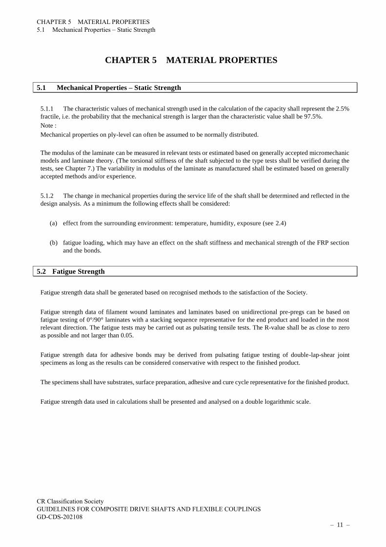
Table 6-1 Safety Factors
Part Failure mechanism SF
Central section of shaft
Joint
Fibre failure 3.0 - 4.0(1)
Central section of shaft
Joint
Matrix cracking 1.5
Central section of shaft
Joint
Delamination – shear
Delamination – through-
thickness stress
(2)
4.0
Central section of shaft Buckling 3.0
Joint: adhesive bond Shear of adhesive bond-line 6.0(3)
Joint: pin/bolt connection Contact pressure 5.0(3)
Notes:
(1) For designs with SF ≥ 4.0 design against fatigue due to torsion will normally not be required,
see 6.3 For designs with 3.0 ≤ SF < 4.0 documentation of the slope “m” of the fatigue curve of
the material will be required for design against torsion fatigue, see 6.3. For fatigue with respect
to other load conditions (e.g. deformations in flexible couplings) other requirements apply, see
6.3.
(2) To ensure an adequate safety against delamination the through thickness shear stress in the
laminate including residual stresses shall not exceed 5 MPa at any location.
(3) The capacity of the joint will be based on static tests in addition to the design analyses, see
Chapter 7. The manufacturer shall provide a calculation procedure for applying the test results
to other shaft designs included in the type approval to the satisfaction of the Society.
The shaft’s/coupling’s strength with respect to buckling shall be determined by FEM calculations supported by the type
tests, see Ch.7. The FEM analysis and/or tests shall be carried out in such a way that conservative predictions of the
buckling strength are obtained. The safety factor SF shall apply to this conservative prediction. If the buckling strength
of the component is based on realistic tests in full scale taking into account all relevant imperfections (e.g. geometrical)
a SF lower than stated in Table 1 may be accepted.
6.1.3 For long cylindrical cross sections the critical buckling stress in torsion can be calculated according to the
following equation as an alternative to FEM-analyses or tests:
𝜏crit =𝐸
1 − ν2× (
𝑡
𝑙)
2
× (−2.39 + √96.9 + 0.605 × 𝐻1.5)
𝐻 = √1 − 𝜈2 ×𝑙2
𝑟 × 𝑡
6.1.4 For long cylindrical cross sections the critical buckling stress in bending can be calculated according to the
following equation as an alternative to FEM-analyses or tests:
𝜎crit =𝐸
𝜋(1 − 𝜈2)×
𝑡
𝑟
τcrit = critical shear stress due to torsion
σcrit = critical bending stress
r = inner radius of cylindrical section
t = minimum thickness of laminate in central section

CHAPTER 6 DESIGN ANALYSES
6.2 Calculation of Stiffness
CR Classification Society
GUIDELINES FOR COMPOSITE DRIVE SHAFTS AND FLEXIBLE COUPLINGS
GD-CDS-202108
– 14 –
l = length of central section between flanges
E = the lowest of the engineering moduli in longitudinal and circumferential direction of the shaft central
section.
ν = the lowest of the Poison ratios of the shaft central section.
The equations are valid for r/t > 10.
Combined loading shall be checked according to the following formula:
τcrit/τ+ σcrit/σ ≥ SF
where σ and τ refers to the extreme bending stress and extreme torsional stress in the central section.
6.2 Calculation of Stiffness
6.2.1 The torsional and bending stiffnesses of a shaft and the relevant stiffness parameters of a coupling shall be
calculated by the same analytical approach as specified in 6.1. The variability in the modulus of the material shall be
included in a conservative way in the analysis.
6.3 Fatigue Strength
6.3.1 Torsion
The fatigue strength of the drive shaft(s)/flexible coupling(s) with respect to torsion shall be demonstrated based on the
chosen safety factors (SF) in the design as specified in 6.1. Procedures for calculation of the fatigue strength of the drive
shaft/ flexible coupling design(s) included in the PTAC shall be based on generally accepted principles and they shall
be submitted as part of the type approval documentation.
SF ≥ 4.0; for designs with respect to fibre failure, design against torsion fatigue will normally not be required.
Note :
This is based on the assumption that the slope “m” of the fatigue curve of the FRP material used is at least m ≥ 10 where
m is defined by N ~ Δσ-m (i.e. the number of load cycles to failure is inversely proportional to the stress range raised to
the power of m, see ANNEX 1). This combination of SF and “m” will give a fatigue strength of the central section
exceeding the rules requirements for the fatigue strength of the metallic end flanges. For reinforcement materials and
combinations of reinforcement and matrix materials where “m” may take on a lower value or for materials for which
sufficient knowledge regarding their fatigue characteristics has not yet been accumulated, documentation of fatigue
properties of the drive shaft/flexible coupling will be required.
3.0 ≤ SF < 4.0; for designs with respect to fibre failure, documentation of the torsion fatigue properties (for torsion in
any part of the drive shaft/flexible coupling) including the slope “m” of the fatigue curve of the material will be required.
“m” shall exceed 12.
For fatigue with respect to other load conditions (e.g. deformations in flexible couplings) other requirements apply, see
Other load conditions. Requirements to fatigue testing (other than full scale test) are given in 5.2.
It shall be documented that the slope m of the fatigue curve of the adhesive bond is larger than or equal to m ≥ 7.0.
Note :
This combination of SF and m will give a fatigue strength of the adhesive bond exceeding the guidelines requirements
for the fatigue strength of the metallic end flanges. For bond materials and designs where “m” may take on a lower value
or for materials for which sufficient knowledge regarding their fatigue characteristics has not yet been accumulated,
documentation of fatigue properties of the drive shaft/flexible coupling will be required.
As an alternative the fatigue strength can be demonstrated by full scale testing according to the procedure specified in
7.3.
6.3.2 Other load conditions
CHAPTER 6 DESIGN ANALYSES
6.3 Fatigue Strength
CR Classification Society
GUIDELINES FOR COMPOSITE DRIVE SHAFTS AND FLEXIBLE COUPLINGS
GD-CDS-202108
– 15 –
The fatigue strength with respect to other load conditions shall be demonstrated by similar methods as for torsion, except
that the provisions based on the level of SF do not apply. For flexible couplings a full fatigue analyses with respect to
the relevant allowable misalignments will normally be required. Full scale testing may be required for complicated
designs and for designs with a high degree of utilisation. All relevant conditions shall be considered in the analyses, i.e.
as a minimum torsion, bending, axial and radial offset and angular misalignment as relevant.
All requirements to fatigue strength is based on the assumption that the residual strength of the drive shaft/flexible
coupling will never be lower than 90% of the original value during the drive shaft’s/flexible coupling’s service life. If
the reduction is larger the drive shaft/flexible coupling will be subject to special consideration.

CHAPTER 7 TYPE TESTING
7.1 General
CR Classification Society
GUIDELINES FOR COMPOSITE DRIVE SHAFTS AND FLEXIBLE COUPLINGS
GD-CDS-202108
– 16 –
CHAPTER 7 TYPE TESTING
7.1 General
7.1.1 At least one drive shaft/flexible coupling design shall be tested with respect to properties under static torsional
load. Fatigue testing shall be carried out as required in the preceding chapters. If the bending moment in the shaft is
significant, testing with bending moments may also be required.
7.2 Test Specimens
7.2.1 At least one test specimen shall be prepared for testing of the static strength. Specimens for fatigue testing shall
be prepared as agreed with the Society. The test specimens shall be representative for the normal production. The same
materials and fabrication methods as applied in the normal production shall be used when fabricating the specimens.
The nominal torque of the specimen(s) for testing shall be at least equal to 30% of the maximum nominal torque included
in the range for which the type approval shall apply.
For shafts the length of the central section between the innermost edges of the end flanges shall be at least equal to 3
times the outside diameter of the central section. For particular designs where the length of the component is less than
3 times the diameter the requirement to the length of the specimen may be waived.
The interface between the central section and the end flanges shall be identical in design to normal production shafts.
Modifications to the metallic flanges for testing purposes, not affecting the performance of the joint are acceptable.
7.3. Test under Static Load
The purpose of the test is to verify that the calculated torsional strength and stiffness of the shaft will be reached in
actual production with a certain level of confidence. As a minimum one test shall be carried out.
7.3.1 Instrumentation:
The following instrumentation shall be included:
(a) equipment for continuously measuring the torque with an uncertainty < 4%.
(b) equipment for continuously measuring the twist between the end flanges with an uncertainty to be agreed in
each case.
(c) equipment for continuous (or equivalent) logging of torque and twist.
It is recommended that additional equipment such as e.g. strain gauges are included to gain further
information regarding the performance of the shaft and to verify the design calculations.
7.3.2 Test environment:
The test shall be carried out in a temperature within the range 22 ± 5°C and with a relative humidity within the range
35% – 90% unless otherwise agreed.
7.3.3 Test procedure:
The specimen shall be loaded in pure torsion. Four load sequences shall be carried out:
Seq. 1-3: the shaft shall be loaded to peak torque and back to zero torque three times
CHAPTER 7 TYPE TESTING
7.4. Full Scale Fatigue Testing
CR Classification Society
GUIDELINES FOR COMPOSITE DRIVE SHAFTS AND FLEXIBLE COUPLINGS
GD-CDS-202108
– 17 –
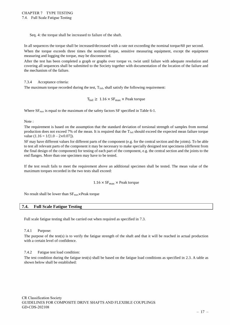
Seq. 4: the torque shall be increased to failure of the shaft.
In all sequences the torque shall be increased/decreased with a rate not exceeding the nominal torque/60 per second.
When the torque exceeds three times the nominal torque, sensitive measuring equipment, except the equipment
measuring and logging the torque, may be disconnected.
After the test has been completed a graph or graphs over torque vs. twist until failure with adequate resolution and
covering all sequences shall be submitted to the Society together with documentation of the location of the failure and
the mechanism of the failure.
7.3.4 Acceptance criteria:
The maximum torque recorded during the test, Tfail, shall satisfy the following requirement:
Tfail ≥ 1.16 × SFmax × Peak torque
Where SFmax is equal to the maximum of the safety factors SF specified in Table 6-1.
Note :
The requirement is based on the assumption that the standard deviation of torsional strength of samples from normal
production does not exceed 7% of the mean. It is required that the Tfail should exceed the expected mean failure torque
value (1.16 = 1/[1.0 – 2×0.07]).
SF may have different values for different parts of the component (e.g. for the central section and the joints). To be able
to test all relevant parts of the component it may be necessary to make specially designed test specimens (different from
the final design of the component) for testing of each part of the component, e.g. the central section and the joints to the
end flanges. More than one specimen may have to be tested.
If the test result fails to meet the requirement above an additional specimen shall be tested. The mean value of the
maximum torques recorded in the two tests shall exceed:
1.16 × SFmax × Peak torque
No result shall be lower than SFmax×Peak torque
7.4. Full Scale Fatigue Testing
Full scale fatigue testing shall be carried out when required as specified in 7.3.
7.4.1 Purpose:
The purpose of the test(s) is to verify the fatigue strength of the shaft and that it will be reached in actual production
with a certain level of confidence.
7.4.2 Fatigue test load condition:
The test condition during the fatigue test(s) shall be based on the fatigue load conditions as specified in 2.3. A table as
shown below shall be established:

CHAPTER 7 TYPE TESTING
7.4. Full Scale Fatigue Testing
CR Classification Society
GUIDELINES FOR COMPOSITE DRIVE SHAFTS AND FLEXIBLE COUPLINGS
GD-CDS-202108
– 18 –
Condition Mean Amplitude Range Cycles
1 M1 A1 ΔT1 N1
2 M2 A2 ΔT2 N2
3 M3 A3 ΔT3 N3
etc. etc.
where:
Mi = mean torque for condition “i”.
Ai = torque amplitude for condition “i”.
ΔTi = equivalent torque range for condition “i”.
Ni = number of load cycles for condition “i”.
The equivalent torque range is defined for R = 0. ΔTi is calculated according to the following equation:
ΔTi =2 × Ai
1 −MiUT
+AiUT
UT = ultimate torsional strength of the central section as measured in the static test.
Note :
The equation is based on the assumption that the fatigue strength of the component can be described by straight line in
a Haigh-diagram where the line intersects the x-axis (mean load) at UT.
7.4.3 Definition of safety margin:
The safety margin applied in the fatigue test is composed of two elements:
(a) to account for possible sequence effects from the service fatigue load history.
(b) to ensure an adequate reliability of the shaft with respect to fatigue failure.
Note :
A composite shaft should have the same reliability with respect to fatigue failure as the corresponding steel shaft.
To account for the first requirement the factor F1 is set to F1 = 5.
To account for the second requirement the factor F2 is set to F2 = 102log(σ) where log(σ) is equal to the standard deviation
of the logarithm of the fatigue life. In lack of more precise information log(σ) can be set equal to 0.4. (Log(x) corresponds
to the 10-base logarithm).
F1×F2 shall not be taken smaller than 32.
7.4.4 Definition of minimum required fatigue curves:
For each condition “i” calculate mi and Ci according to the following equation:
mi =[log(Ni) + log(F1) + log(F2)]
[log(UT) − log(∆Ti)]
Ci = UTmi
Note :
It is assumed that the fatigue strength of the component can be represented by the following expression (i.e. a linear
representation in a log-log-diagram): N = C×ΔT-m.

CHAPTER 7 TYPE TESTING
7.4. Full Scale Fatigue Testing
CR Classification Society
GUIDELINES FOR COMPOSITE DRIVE SHAFTS AND FLEXIBLE COUPLINGS
GD-CDS-202108
– 19 –
Determine the required fatigue curve:
m = maxi(mi)
C = maxi(Ci)
7.4.5 Fatigue damages:
Calculate the fatigue damage for each condition “i”:
Di =Ni
C× ∆Ti
−m
Calculate the total fatigue damage and relative fatigue damages:
Dtotal = ΣiDi total fatigue damage di = relative fatigue damage for condition “i”
Note :
It is assumed that linear damage accumulation (Miner’s Rule) is representative.
7.4.6 Fatigue test condition:
Determine the fatigue test condition ΔTtest and Ntest such that the following two conditions are satisfied:
Ntest =C × ΔTtest
−m
maxi(δi)
2×mini (Ai) ≤ ΔTtest ≤ torque at onset of matrix cracking1
Note 1: as determined by the design calculations
7.4.7 Instrumentation:
The following instrumentation shall be included:
(a) equipment for continuously measuring the torque with an uncertainty < 5%.
(b) equipment for continuously measuring the twist between the end flanges with an uncertainty to be agreed in
each case.
(c) equipment for continuous (or equivalent) logging of torque and twist.
It is recommended that additional equipment such as e.g. strain gauges are included to gain further
information regarding the performance of the shaft and to verify the design calculations.
7.4.8 Test environment
The test shall be carried out in a temperature within the range 22 ± 5°C and with a relative humidity within the range 35
– 90% unless otherwise agreed.
7.4.9 Test procedure
The specimen shall be loaded in pure torsion.
The following sequence shall be followed:

CHAPTER 7 TYPE TESTING
7.4. Full Scale Fatigue Testing
CR Classification Society
GUIDELINES FOR COMPOSITE DRIVE SHAFTS AND FLEXIBLE COUPLINGS
GD-CDS-202108
– 20 –
(a) the shaft shall be loaded to extreme torque and the load released three times. The torque shall be
increased/decreased monotonously with a rate not exceeding the nominal torque/60 per second
(b) the torsional stiffness is measured
(c) fatigue test at the following conditions:
range of torque: ΔTtest
R-ratio: ≤ 0.05
number of load cycles: the larger of Ntest or 5×10⁶ load cycles, or to failure.
(d) the torsional stiffness shall be measured at N test
During sequence 3 the equipment for measurement of twist may be disconnected.
7.4.10 Acceptance criteria:
In case the number of load cycles to failure Nfail > Ntest the test result is acceptable.
In case the shaft fails at Nfail < Ntest an additional fatigue test shall be carried out. The mean value of the log(Nfail) for the
two tests shall be larger than log(Ntest).
In case the shaft fails at a number of load cycles Nfail < Ntest/102 log(σ) the test result is unacceptable.
No failure signifies that no failures or damages of any kind are observed on the FRP central section or in the bonds
between central sections and end flanges after completion of the test. After completion of the test the bonds on the shaft
shall be inspected carefully such that it can be ascertained that no damages to the bonds have occurred. Normally this
will mean that the bond have to be cut through the thickness at least 4 locations around the circumference of the bond
such that the bond line is exposed for inspection.

CHAPTER 8 DOCUMENTATION REQUIRED FOR EACH DELIVERY
8.1 Proof Testing
CR Classification Society
GUIDELINES FOR COMPOSITE DRIVE SHAFTS AND FLEXIBLE COUPLINGS
GD-CDS-202108
– 21 –
CHAPTER 8 DOCUMENTATION REQUIRED FOR EACH DELIVERY
8.1 Proof Testing
8.1.1 All shafts and couplings shall be torque tested to 1.5 times the peak torque before delivery.
If adequate QA and QC procedures are available and implemented the requirement to proof testing of some or all of the
delivered items may be waived. Such QA and QC procedures and their implementation shall be accepted by the Society
prior to start of manufacture.
8.2 Design Documentation
8.2.1 Design analysis as specified in this class programme shall be documented and filed for each design and shall
be made available to the Society on request.
8.3 Requirements to Production and Quality Control Arrangement
8.3.1 The manufacturer should have a quality system that meets ISO 9001 standards, or equivalent. If this quality
standard is not fulfilled, the extent of type testing and assessments will be specially considered.
The quality control arrangement shall include all activities and parameters relevant for the quality of the end product.
As a minimum the following items shall be considered:
(a) design and calculation procedures and methods
(b) documentation of design
(c) control of incoming materials
(d) test equipment, test methods, test samples and reference to standards used
(e) fabrication procedures
(f) cure cycles
(g) traceability and marking systems
(h) production logs and test reports

CHAPTER 9 REQUIREMENTS FOR MARKING OF PRODUCT
9.1 General
CR Classification Society
GUIDELINES FOR COMPOSITE DRIVE SHAFTS AND FLEXIBLE COUPLINGS
GD-CDS-202108
– 22 –
CHAPTER 9 REQUIREMENTS FOR MARKING OF PRODUCT
9.1 General
9.1.1 The pipes and fittings shall be marked. The marking shall at least include the following information:
(a) manufacturer's name and/or logo
(b) type designation
(c) materials
(d) size/dimensions
(e) date of fabrication and/or serial number.
The marking shall be carried out in such a way that it is visible, legible and indelible. The marking of product shall
enable traceability to the PTAC.

ANNEX 1 FATIGUE DESIGN OF STEEL STRUCTURES
A1.1 General
CR Classification Society
GUIDELINES FOR COMPOSITE DRIVE SHAFTS AND FLEXIBLE COUPLINGS
GD-CDS-202108
– 23 –
ANNEX 1 FATIGUE DESIGN OF STEEL STRUCTURES
A1.1 General
The classified fatigue design curves adopted in Eurocode 3, are the same as proposed in the " Recommendations for the
Fatigue Design of Steel Structures" published by the organization of European Convention for Construction Steelwork.
The Recommendations were one of the first attempts to provide uniformity to the determination of the fatigue strength
design curves.
The Recommendations define a set of equally spaced S-N curves plotted on a log-log scale. Reference to these curves
allows a detail category to be classified (representative) of a particular structural detail which corresponds to a notch
effect or a characteristic geometrical discontinuity. This classification has been determined by a series of fatigue test
results, from which a statistical and a probabilistic evaluation is performed.
Each individual fatigue strength curve of steel is defined in a conventional way (Fig.A1-1) by a slope constant of m = 3
(slope = -1/3). The constant amplitude limit is set at 5 million cycles. The slope constant m = 3 was a best fit for a large
number of different structural details tested in fatigue. The figure of 5 million cycles for the constant amplitude fatigue
limit is a compromise between 2 million cycles for "good" details and 10 million cycles for details which create a severe
notch effect. For any stress range of constant amplitude below this limit, no fatigue damage is expected to occur.
Fig. A1-1 Normalized S-N curve of steel
A1.2 Terms and definitions
A1.2.1 Fatigue loading parameters
(a) loading event
A defined loading sequence applied to the structure and giving rise to a stress history, which is normally
repeated a defined number of times in the life of the structure.
(b) stress history
A record or a calculation of the stress variation at a particular point in a structure during a loading event.
(c) stress range
Fatigue strength curve
logΔσ
ΔσC ΔσD ΔσL
NC ND NL
Constant amplitude fatigue limit
Cut-off limit
2.106 5.106 10.106 log N
m=5
m=3
1
1

ANNEX 1 FATIGUE DESIGN OF STEEL STRUCTURES
A1.2 Terms and definitions
CR Classification Society
GUIDELINES FOR COMPOSITE DRIVE SHAFTS AND FLEXIBLE COUPLINGS
GD-CDS-202108
– 24 –
The algebraic difference between the two extremes of a particular stress cycle derived from a stress history.
(d) stress-range spectrum
Histogram of the number of occurrences for all stress ranges of different magnitudes recorded or calculated
for a particular loading event.
(e) design spectrum
The total of all stress-range spectra in the design life of a structure relevant to the fatigue assessment.
(f) design life
The reference period of time for which a structure is required to perform safely with an acceptable probability
that failure by fatigue cracking will not occur.
(g) fatigue life
The predicted period of time to cause fatigue failure under the application of the design spectrum.
(h) fatigue loading
A set of action parameters based on typical loading events described by the positions of loads, their
magnitudes, frequencies of occurrence, sequence and relative phasing.
(i) equivalent constant amplitude fatigue loading
Simplified constant amplitude loading causing the same fatigue damage effects as a series of actual variable
amplitude loading events.
A1.2.2 Fatigue strength
(a) fatigue strength curve
The quantitative relationship between the stress range and number of stress cycles to fatigue failure, used for
the fatigue assessment of a particular category of structural detail.
(b) detail category
The numerical designation given to a particular detail for a given direction of stress fluctuation, in order to
indicate which fatigue strength curve is applicable for the fatigue assessment (The detail category number
indicates the reference fatigue strength ΔσC in N/mm2).
(c) constant amplitude fatigue limit
The limiting direct or shear stress range value below which no fatigue damage will occur in tests under
constant amplitude stress conditions. Under variable amplitude conditions all stress ranges have to be below
this limit for no fatigue damage to occur.
(d) cut-off limit
Limit below which stress ranges of the design spectrum do not contribute to the calculated cumulative
damage.
(e) endurance
The life to failure expressed in cycles, under the action of a constant amplitude stress history.

ANNEX 1 FATIGUE DESIGN OF STEEL STRUCTURES
A1.3 Fatigue strength
CR Classification Society
GUIDELINES FOR COMPOSITE DRIVE SHAFTS AND FLEXIBLE COUPLINGS
GD-CDS-202108
– 25 –
(f) reference fatigue strength
The constant amplitude stress range ΔσC, for a particular detail category for an endurance N=2x10⁶ cycles.
A1.2.3 Symbols
Δσ stress range (direct stress)
Δτ stress range (shear stress)
ΔσC,ΔτC reference value of the fatigue strength at NC 2 million cycles
ΔσD,ΔτD fatigue limit for constant amplitude stress ranges at the number of cycles
ΔσL,ΔτL cut-off limit for stress ranges at the number of cycle NL
NR design life time expressed as number of cycles related to a constant stress range
A1.3 Fatigue strength
A1.3.1 General
(a) The fatigue strength for nominal stress ranges is represented by a series of (logΔσR) - (logN) curves and
(logΔτR) - (logN) curves (S-N-curves), which correspond to typical detail categories. Each detail category is
designated by a number which represents, in N/mm2, the reference value ΔσC and ΔτC for the fatigue strength
at 2 million cycles.
(b) For constant amplitude nominal stress ranges the fatigue strength can be obtained as follows:
∆𝜎𝑅𝑚𝑁𝑅 = ∆𝜎𝐶
𝑚2 × 10⁶ 𝑤𝑖𝑡ℎ 𝑚 = 3 𝑓𝑜𝑟 𝑁 ≤ 5 × 10⁶
∆𝜏𝑅𝑚𝑁𝑅 = ∆𝜏𝐶
𝑚2 × 10⁶ 𝑤𝑖𝑡ℎ 𝑚 = 5 𝑓𝑜𝑟 𝑁 ≤ 108
∆𝜎𝐷 = (2
5)
13⁄
∆𝜎𝐶 = 0.737∆𝜎𝐶is the constant amplitude fatigue limit
∆𝜏𝐿 = (2
100)
15⁄
∆𝜏𝐶 = 0.457∆𝜏𝐶 is the cut-off limit
(c) For nominal stress spectra with stress ranges above and below the constant amplitude fatigue limit ΔσD the
fatigue strength should be based on the extended fatigue strength curves as follows:
∆𝜎𝑅𝑚𝑁𝑅 = ∆𝜎𝐶
𝑚2 × 10⁶ 𝑤𝑖𝑡ℎ 𝑚 = 3 𝑓𝑜𝑟 𝑁 ≤ 5 × 10⁶
∆𝜎𝑅𝑚𝑁𝑅 = ∆𝜎𝐷
𝑚5 × 10⁶ 𝑤𝑖𝑡ℎ 𝑚 = 5 𝑓𝑜𝑟 5 × 10⁶ ≤ 𝑁 ≤ 108
∆𝜎𝐿 = (5
100)
15⁄
∆𝜎𝐷 = 0.549∆𝜎𝐷 is the cut-off limit

ANNEX 1 FATIGUE DESIGN OF STEEL STRUCTURES
A1.3 Fatigue strength
CR Classification Society
GUIDELINES FOR COMPOSITE DRIVE SHAFTS AND FLEXIBLE COUPLINGS
GD-CDS-202108
– 26 –
Fig. A1-2 Fatigue strength curves for direct stress ranges
Fig. A1-3 Fatigue strength curves for shear stress ranges
NOTE:
When test data were used to determine the appropriate detail category for a particular constructional detail, the value of
the stress range, ΔσC corresponding to a value of NC = 2 million cycles were calculated for a 75% confidence level of
95% probability of survival for log N, taking into account the standard deviation and the sample size and residual stress
effects. The number of data points (not lower than 10) was considered in the statistical analysis.
1 Detail category ΔσC
2 Constant amplitude fatigue limit ΔσD
3 Cut-off limit ΔσL
Endurance, number of cycles N
Dir
ect
stre
ss r
ange
Δσ
R [N
/mm
2]
1
2
3
m = 5
m = 3
1000
100
10
1
125 112 100 90 80 71 63 56 50 45 40 36
160 140
104 10
5 10
6 10
7 10
8 10
9 2*106 5*106
1 Detail category ΔτC
2 Cut-off limit ΔτL
Endurance, number of cycles N
Sh
ear
stre
ss r
ange
Δτ R
[N
/mm
2]
m = 5
1
10
100
1000
100
80
104 105 106 107 108 109
1
2


![Cellulose Nanofibril Composite Substrates for Flexible ... · PDF fileCellulose Nanofibril Composite Substrates for Flexible Electronics ... electronic devices is ongoing [1].](https://img.dokumen.tips/doc/110x75/5a87b1617f8b9a9f1b8df19a/cellulose-nanofibril-composite-substrates-for-flexible-nanofibril-composite.jpg)