Embed Size (px)
Citation preview
Guided Wave Radar
Level Transmitter
Enhanced Model 705 withFOUNDATION Fieldbus™ Digital Output
705 software v3.x
FOUNDATION Fieldbus™ Operating Manual

57-640 Eclipse Guided Wave Radar Transmitter - FOUNDATION fieldbus™
Read this Manual Before InstallingThis manual provides information on the EnhancedEclipse Model 705 transmitter with FOUNDATION fieldbus™
Output and should be used in conjunction with EclipseI&O manual 57-600. It is important that all instruc-tions are read and followed carefully.
Safety MessagesThe Eclipse system is designed for use in Category II,Pollution Degree 2 installations. Follow all standardindustry procedures for servicing electrical and computerequipment when working with or around high voltage.Always shut off the power supply before touching anycomponents. Although high voltage is not present in thissystem, it may be present in other systems.
Electrical components are sensitive to electrostatic dis-charge. To prevent equipment damage, observe safetyprocedures when working with electrostatic sensitivecomponents.
This device complies with Part 15 of the FCC rules.Operation is subject to the following two conditions:(1) This device may not cause harmful interference, and(2) This device must accept any interference received,including interference that may cause undesired operation.
WARNING! Explosion hazard. Do not connect or dis-connect designs rated Explosion proof or Non-incendiveunless power has been switched off and/or the area isknown to be non-hazardous
Low Voltage DirectiveFor use in Installations Category II, Pollution Degree 2.If equipment is used in a manner not specified by themanufacturer, protection provided by equipment may beimpaired.
Notice of Copyright and LimitationsCopyright © 2006 Magnetrol International©2005 (Rev. 2006) Fieldbus Foundation™
All rights reserved
Magnetrol reserves the right to make changes to theproduct described in this manual at any time withoutnotice. Magnetrol makes no warranty with respect to theaccuracy of the information in this manual.
WarrantyAll Magnetrol/STI electronic level and flow controls arewarranted free of defects in materials or workmanship forone full year from the date of original factory shipment.If returned within the warranty period; and, upon factoryinspection of the control, the cause of the claim is deter-mined to be covered under the warranty; then,Magnetrol/STI will repair or replace the control at nocost to the purchaser (or owner) other than transportation.
Magnetrol/STI shall not be liable for misapplication,labor claims, direct or consequential damage or expensearising from the installation or use of equipment. Thereare no other warranties expressed or implied, except spe-cial written warranties covering some Magnetrol/STIproducts.
Quality assuranceThe quality assurance system in place at Magnetrol/STIguarantees the highest level of quality throughout thecompany. Magnetrol is committed to providing fullcustomer satisfaction both in quality products andquality service.
Magnetrol’s quality assurance system isregistered to ISO 9001 affirming itscommitment to known internationalquality standards providing the strongestassurance of product/service qualityavailable.

Table of Contents
1.0 FOUNDATION fieldbus™ Overview ...................................11.1 Description ...............................................................11.2 Benefits .....................................................................21.3 Device Configuration................................................21.4 Intrinsic Safety ..........................................................31.5 Link Active Scheduler (LAS) .....................................3
2.0 QuickStart Installation ...................................................42.1 Getting Started..........................................................4
2.1.1 Equipment and Tools .....................................42.1.2 Configuration Information.............................5
2.2 QuickStart Mounting................................................52.2.1 Probe..............................................................52.2.2 Transmitter.....................................................6
2.3 QuickStart Wiring ....................................................62.4 QuickStart Configuration .........................................7
3.0 Complete Installation.....................................................83.1 Unpacking ................................................................83.2 Electrostatic Discharge (ESD) Handling Procedure...83.3 Before You Begin.......................................................9
3.3.1 Site Preparation ..............................................93.3.2 Equipment and Tools .....................................93.3.3 Operational Considerations............................9
3.4 Mounting..................................................................93.4.1 Installing a Coaxial Probe.............................10
3.4.1.1 To install a coaxial probe.......................103.4.2 Installing a Twin Rod Probe .........................11
3.4.2.1 To install a rigid twin rod probe............113.4.2.2 To install a Model 7x7 standard
flexible twin rod probe ..........................123.4.3 Installing a Single Rod Probe .......................12
3.4.3.1 Installing a rigid probe ..........................133.4.3.2 Installing a flexible probe ......................13
3.4.4 Installation Guidelines–Models 7x2/7x5 Bulk Solids Probes .............14
3.4.4.1 Applications ..........................................143.4.4.2 Mounting recommendations .................143.4.4.3 To install a bulk solids twin rod probe ..143.4.4.4 To install a bulk solids single rod probe 15
3.4.5 Installing the Transmitter .............................163.4.5.1 Integral Mount......................................163.4.5.2 Remote Mount......................................16
4.0 Function Blocks............................................................174.1 Overview.................................................................17
4.1.1 Universal Fieldbus Block Parameters ............174.2 Resource Block........................................................184.3 GWR Transducer Block ..........................................21
4.3.1 GWR Transducer Block Parameters..............214.3.2 Password Parameters.....................................214.3.3 Configuration Parameters.............................224.3.4 Offset Description........................................23
4.4 Calibration Parameters ............................................244.4.1 Factory Parameters .......................................244.4.2 Firmware Version .........................................25
4.5 Analog Input Block.................................................254.5.1 AI Block Parameters .....................................25
6.0 Diagnostic Parameters ..................................................286.1 Simulation Feature ..................................................29
7.0 Documentation ............................................................297.1 Data Sheet for Individual Instrument .....................307.2 Data sheet for Multiple Devices ..............................31
8.0 Reference Information..................................................328.1 Troubleshooting ......................................................32
8.1.1 Troubleshooting System Problems................328.1.2 Error Messages .............................................338.1.3 FF Segment Checklist ..................................35
8.2 Agency Approvals .....................................................368.2.1 Agency Specifications –
FOUNDATION fieldbus™ System ....................378.3 Specifications ..........................................................38
8.3.1 Functional ....................................................388.3.2 Performance – Model 705............................398.3.3 Performance – Model 705 Interface .............40
8.4 Parts ........................................................................418.4.1 Replacement Parts ........................................418.4.2 Recommended Spare Parts ...........................41
8.5 Model Numbers ......................................................428.5.1 Transmitter...................................................428.5.2 Probe............................................................43
8.6 References ...............................................................46Appendix ...............................................................46Configuration Data Sheet .....................................47
FOUNDATION Fieldbus™ Enhanced Eclipse Model 705Guided Wave Radar Transmitter
57-640 Eclipse Guided Wave Radar Transmitter - FOUNDATION fieldbus™

1.0 FOUNDATION Fieldbus™ Overview
1.1 Description
FOUNDATION fieldbus™ is a digital communications systemthat serially interconnects devices in the field. A Fieldbussystem is similar to a Distributed Control System (DCS)with two exceptions:
• Although a FOUNDATION fieldbus™ system can use the samephysical wiring as an existing 4–20 mA device, Fieldbusdevices are not connected point to point, but rather aremultidropped and wired in parallel on a single pair of wires(referred to as a segment).
• FOUNDATION fieldbus™ is a system that allows the user todistribute control across a network. Fieldbus devices aresmart and actually maintain control over the system.
Unlike 4–20 mA analog installations in which the two wirescarry a single variable (the varying 4–20 mA current), a digi-tal communications scheme such as FOUNDATION fieldbus™
considers the two wires as a network. The network can carrymany process variables as well as other information. TheEnhanced Eclipse Model 705FF transmitter is aFOUNDATION fieldbus™ registered device that communicateswith the H1 FOUNDATION fieldbus™ protocol operating at31.25 kbits/sec. The H1 physical layer is an approvedIEC 61158 standard.
An IEC61158 shielded twisted pair wire segment can be aslong as 6234 feet (1900 meters) without a repeater. Up to4 repeaters per segment can be used to extend the distance.The maximum number of devices allowed on a Fieldbussegment is 32 although this depends on the current drawof the devices on any given segment.
1 57-640 Eclipse Guided Wave Radar Transmitter - FOUNDATION fieldbus™
Control Room
Power Supply
Terminator
6234 feet (1900 meters) maximum
PC
Terminator
PowerConditioner
Typical Fieldbus Installation
Details regarding cable specifications, grounding, termination,and other network information can be found in IEC 61158or the wiring installation application guide AG-140 atwww.fieldbus.org.
1.2 Benefits
The benefits of FOUNDATION fieldbus™ can be foundthroughout all phases of an installation:
1. Design/Installation: Connecting multiple devices to a singlepair of wires means less wire and fewer I/O equipment.Initial Engineering costs are also reduced because theFieldbus Foundation requires interoperability, defined as“the ability to operate multiple devices in the same system,regardless of manufacturer, without a loss of functionality.”
All FOUNDATION fieldbus™ devices must be tested forinteroperability by the Fieldbus Foundation. MagnetrolModel 705FF device registration information can be foundat www.fieldbus.org.
2. Operation: With control now taking place within thedevices in the field, better loop performance and control arethe result. A FOUNDATION fieldbus™ system allows for mul-tiple variables to be brought back from each device to thecontrol room for additional trending and reporting.
3. Maintenance: The self-diagnostics residing in the smartfield devices minimizes the need to send maintenancepersonnel to the field.
1.3 Device Configuration
Device Descriptions
The function of a FOUNDATION fieldbus™ device is deter-mined by the arrangement of a system of blocks defined bythe Fieldbus Foundation. The types of blocks used in a typi-cal User Application are described as follows:
Resource Block describes the characteristics of theFOUNDATION fieldbus™ device such as the device name,manufacturer, and serial number.
Function Blocks are built into the FOUNDATION fieldbus™
devices as needed to provide the desired control systembehavior. The input and output parameters of functionblocks can be linked over the Fieldbus. There can benumerous function blocks in a single User Application.
Transducer Blocks contain information such as calibrationparameters and sensor type. They are used to connect thesensor to the input function blocks.
257-640 Eclipse Guided Wave Radar Transmitter - FOUNDATION fieldbus™

An important requirement of Fieldbus devices is the inter-operability concept mentioned earlier. Device Description(DD) technology is used to achieve this interoperability.The DD provides extended descriptions for each object andprovides pertinent information needed by the host system.
DDs are similar to the drivers that your personal computer(PC) uses to operate peripheral devices connected to it. AnyFieldbus host system can operate with a device if it has theproper DD and Common File Format (CFF) for that device.
The most recent DD and CFF files can be found on theFOUNDATION fieldbus™ web site at fieldbus.org.
1.4 Intrinsic Safety
The H1 physical layer supports Intrinsic Safety (IS) applica-tions with bus-powered devices. To accomplish this, an ISbarrier or galvanic isolator is placed between the powersupply in the safe area and the device in the hazardous area.
H1 also supports the Fieldbus Intrinsically Safe Concept(FISCO) model which allows more field devices in anetwork. The FISCO model considers the capacitance andinductance of the wiring to be distributed along its entirelength. Therefore, the stored energy during a fault will beless and more devices are permitted on a pair of wires.Instead of the conservative entity model, which only allowsabout 90 mA of current, the FISCO model allows a maxi-mum of 110 mA for Class II C installations and 240 mAfor Class II B installations.
FISCO certifying agencies have limited the maximumsegment length to 1000 meters because the FISCO modeldoes not rely on standardized ignition curves.
The Enhanced Eclipse Model 705 is available with entity IS,FISCO IS, FNICO non-incendive, or explosion proofapprovals.
1.5 Link Active Scheduler (LAS)
The Enhanced Eclipse Model 705 with FOUNDATION fieldbus™
contains a Link Active Scheduler (LAS). The LAS controlsall communication on a FOUNDATION fieldbus™ segment. Itmaintains the “Live List” of all devices on a segment, coor-dinates both the cyclic and acyclic timing and, at any giventime, controls which device publishes data via Compel data(CD) and Pass Token (PT).
3 57-640 Eclipse Guided Wave Radar Transmitter - FOUNDATION fieldbus™

The primary LAS is usually maintained in the host system,but in the event of a failure, all associated control can betransferred to a backup LAS in a field device such as theEnhanced Eclipse Model 705.
2.0 QuickStart Installation
The QuickStart Installation procedures provide the keysteps for mounting, wiring, and configuring the Eclipselevel transmitter. These procedures are intended for experi-enced installers of electronic level measurement instruments.See Complete Installation, Section 3.0, for detailed installa-tion instructions.
WARNING: The Model 7xD, 7xR or 7xT overfill probes should beused for Safety Shutdown/Overfill applications. Allother Guided Wave Radar probes should be installedso the maximum overfill level is a minimum of6" (150 mm) below the process connection. This mayinclude utilizing a nozzle or spool piece to raise theprobe. Consult factory to ensure proper installation.
2.1 Getting Started
Before beginning the QuickStart Installation procedures,have the proper equipment, tools, and information available.
2.1.1 Equipment and Tools
• Open-end wrenches or adjustable wrench to fit the processconnection size and type. Coaxial probe 11⁄2"(38 mm), twin rod probe 17⁄8" (47 mm), transmitter11⁄2" (38 mm). A torque wrench is highly desirable.
• Flat-blade screwdriver
• Cable cutter and 3⁄32" (2.5 mm) hex wrench (Flexible probes only)
• Fieldbus compatible power supply with proper termination
457-640 Eclipse Guided Wave Radar Transmitter - FOUNDATION fieldbus™

5 57-640 Eclipse Guided Wave Radar Transmitter - FOUNDATION fieldbus™
2.1.2 Configuration Information
Some key information is needed to configure the Eclipse transmitter. Complete the following operating parameters table before beginning configuration.
Display Question Answer
Probe Model What probe model is listed on themodel information?(first four digits of probe model number) _____________
Probe Mount Is the probe mounted NPT, BSP,or flange? _____________
Measurement What is the desired measurement? Choices Type are: Level only, Volume, Interface Level
or Interface Level and Volume. _____________
Probe Length What probe length is listed on themodel information?(last three digits of probe model number) _____________
Level Offset The desired level reading when theliquid is at the end of the probe. _____________
Dielectric What is the dielectric constant range of the process medium? (Lower layer dielectric for interface applications) _____________
2.2 QuickStart Mounting
NOTE: Confirm the configuration style and process connectionsize/type of the Eclipse transmitter. Ensure it matches therequirements of the installation before continuing with theQuickStart installation.
� Confirm the model and serial numbers on the nameplatesof the Eclipse probe and transmitter are identical.
For applications using the Model 7xS steam probe, it ismandatory to keep the transmitter and probe matchedas a set.
2.2.1 Probe
� Carefully place the probe into the vessel. Align the probeprocess connection with the threaded or flanged mountingon the vessel.
�
�
��
�
�
��

657-640 Eclipse Guided Wave Radar Transmitter - FOUNDATION fieldbus™
2.2.2 Transmitter
� Tighten the hex nut of the probe process connection orflange bolts.
NOTE: Leave the plastic protective cap in place until ready to install the transmitter. Do not use sealing compound or TFEtape on probe connection to transmitter as this connection issealed by a Viton® O-ring.
� Remove the protective plastic cap from the top of the probeand store for future use. Make sure the top probe connector(female socket) is clean and dry. Clean with isopropylalcohol and cotton swabs if necessary.
� Place the transmitter on the probe. Align the universal connection at the base of the transmitter housing with thetop of the probe. Hand tighten the connection.
� Rotate the transmitter so that it is in the most convenientposition for wiring, configuring, and viewing.
� Using a 11⁄2" (38 mm) wrench, tighten the universal connection on the transmitter 1⁄4 to 1⁄2 turn beyond handtight. A torque wrench is highly recommended to obtain15 ft-lbs. This is a critical connection. DO NOT LEAVEHAND TIGHT.
2.3 QuickStart Wiring
WARNING! Explosion hazard. Do not connect or disconnect equip-ment unless power has been switched off or the area isknown to be non-hazardous.
NOTE: Ensure that the electrical wiring to the Eclipse transmitter iscomplete and in compliance with all regulations and codes.
1. Remove the cover of the upper wiring compartment of thetransmitter.
2. Attach a conduit fitting and mount the conduit plug in thespare opening. Pull the power supply wire through the con-duit fitting.
3. Connect shield to an earth ground at power supply.
4. Connect the positive supply wire to the (+) terminal and thenegative supply wire to the (-) terminal. For ExplosionProof Installations, see Wiring, Section 2.5.3.
5. Replace the cover and tighten.
Blue(typical) (+)
Brown(typical) (-)
(+)
(-)

7 57-640 Eclipse Guided Wave Radar Transmitter - FOUNDATION fieldbus™
2.4 QuickStart Configuration
The Eclipse transmitter comes partially configured fromthe factory but can be reconfigured in the shop (disregardfault message due to unattached probe). The minimumconfiguration instructions required in the field follow. Usethe information from the operating parameters table inSection 1.1.2 before beginning configuration.
1. Power up the transmitter.
The display changes every 5 seconds to show one of threevalues: Status, Level, and %Output.
2. Remove the cover of the lower electronic compartment.
3. Use the Up or Down Arrow ( ) keys to move from onestep of the configuration program to the next step.
4. Press the Enter Arrow ( ) key. The lastcharacter in the first line of the displaychanges to an exclamation point (!).
5. Use the Up or Down Arrow ( ) keys to increase ordecrease the value in the display or to scroll through the choices.
6. Press the Enter Arrow ( ) key to accept a value and move to the next step of the configuration program (the defaultpassword is 1).
7. After entering the last value, allow 10 seconds beforeremoving power from the transmitter.
The following configuration entries are the minimum required forconfiguration (the default password is 1 from the LCD/keypad).
PrbModelxxx
PrbModel(select)
Probe Lnxxx.x
LvlOfstxxx.x
Dielctrc(select)
Select the Probe Model to be usedModel 705: 7xA-x, 7xB-x, 7xD-x, 7xE-x, 7xF-F, 7xF-P,
7xF-4, 7xF-x, 7xJ-x, 7xK-x, 7xP-x, 7xR-x, 7xS-x,7xT-x, 7x1-x, 7x2-x, 7x5-x, 7x7-x
Select the type of Probe Mounting to vessel (NPT, BSP, orflange).
Select from Level Only, Level and Volume, Interface Levelor Interface Level and Volume.
Enter the exact Probe Length as printed on the probenameplate.
Enter the Level Offset value. Refer to Section 2.6.6 forfurther information. (The unit is shipped from the factorywith offset = 0; i.e., all measurements are referenced tothe bottom of the probe).
Enter the Dielectric range for the material to be measured.Level Offset
Probe Length
Probe Mount
Probe Model
Dielectricof Medium
2
5
6
41
�
�
�
�
�
�
PrbMount(select)
Enter
Down
Up
MeasType(select)

857-640 Eclipse Guided Wave Radar Transmitter - FOUNDATION fieldbus™
3.0 Complete Installation
This section provides detailed procedures for properlyinstalling and configuring the Eclipse Guided Wave RadarLevel Transmitter.
3.1 Unpacking
Unpack the instrument carefully. Make sure all componentshave been removed from the packing material. Check all thecontents against the packing slip and report any discrepan-cies to the factory.
Before proceeding with the installation, do the following:
• Inspect all components for damage. Report any damage tothe carrier within 24 hours.
• Make sure the nameplate model number on the probe andtransmitter agree with the packing slip and purchase order.
• Record the model and serial numbers for future referencewhen ordering parts.
Model Number
Serial Number
3.2 Electrostatic Discharge (ESD)Handling Procedure
Magnetrol’s electronic instruments are manufactured to thehighest quality standards. These instruments use electroniccomponents that may be damaged by static electricity pres-ent in most work environments.
The following steps are recommended to reduce the risk ofcomponent failure due to electrostatic discharge.
• Ship and store circuit boards in anti-static bags. If an anti-static bag is not available, wrap the board in aluminum foil.Do not place boards on foam packing materials.
• Use a grounding wrist strap when installing and removing circuit boards. A grounded workstation is recommended.
• Handle circuit boards only by the edges. Do not touchcomponents or connector pins.
• Make sure that all electrical connections are completelymade and none are partial or floating. Ground all equip-ment to a good, earth ground.

3.3 Before You Begin
3.3.1 Site Preparation
Each Eclipse transmitter is built to match the specific physi-cal specifications of the required installation. Make sure theprobe connection is correct for the threaded or flangedmounting on the vessel or tank where the transmitter willbe placed. See Mounting, Section 3.4.
Make sure that the wiring between the power supply andEclipse transmitter are complete and correct for the type ofinstallation.
When installing the Eclipse transmitter in a general purposeor hazardous area, all local, state, and federal regulations andguidelines must be observed. See Wiring, Section 3.5.
3.3.2 Equipment and Tools
No special equipment or tools are required to install theEclipse transmitter. The following items are recommended:
• Open-end wrenches or adjustable wrench to fit the processconnection size and type. Coaxial probe 11⁄2" (38 mm), twinrod probe 17⁄8" (47 mm), transmitter 11⁄2" (38 mm). A torquewrench is highly desirable.
• Flat-blade screwdriver
• Fieldbus compatible power supply with proper termination
3.3.3 Operational Considerations
Operating specifications vary based on Probe modelnumber.
3.4 Mounting
The Eclipse transmitter can be mounted to a tank using avariety of process connections. Generally, either a threadedor flanged connection is used. For information about thesizes and types of connections available, see Probe ModelNumbers, Section 8.5.2.
NOTE: Do not place insulating material around any part of the Eclipsetransmitter including the probe flange as this may cause exces-sive heat buildup.
Make sure all mounting connections are properly in placeon the tank before installing the probe. Compare the name-plate on the probe and transmitter with the product infor-mation; make sure the Eclipse probe is correct for theintended installation.
9 57-640 Eclipse Guided Wave Radar Transmitter - FOUNDATION fieldbus™

1057-640 Eclipse Guided Wave Radar Transmitter - FOUNDATION fieldbus™
WARNING! The Model 7xD, 7xR or 7xT overfill probes should beused for Safety Shutdown/Overfill applications. All otherGuided Wave Radar probes should be installed so themaximum overfill level is a minimum of 6" (150 mm)below the process connection. This may include utilizinga nozzle or spool piece to raise the probe. Consultfactory to ensure proper installation.
WARNING! Do not disassemble probe when in service and underpressure.
3.4.1 Installing a Coaxial Probe(Models 7xA, 7xD, 7xP, 7xR, 7xS, and 7xT)
Before installing, make sure the:
• Model and serial numbers on the nameplates of the Eclipseprobe and transmitter are identical.
• Probe has adequate room for installation and has unob-structed entry to the bottom of the vessel. The Model 7xD(High Temp./High Pressure) probe, Model 7xP (HighPressure) probe, Model 7xR (Overfill) probe, Model 7xS(Steam) probe and Model 7xT (Interface) probe requireadded clearance.
• Process temperature, pressure, dielectric, and viscosity arewithin the probe specifications for the installation.
• Model 7xD (High Temp./High Pressure) probes should behandled with extra care due to the ceramic spacers usedthroughout their length.
3.4.1.1 To install a coaxial probe:
� Make sure the process connection is at least 3⁄4" NPT or aflanged mounting.
� Carefully place the probe into the vessel. Align the gasketon flanged installations.
� Align the probe process connection with the threaded orflanged mounting on the vessel.
� For threaded connections, tighten the hex nut of the probeprocess connection. For flanged connections, tighten flangebolts.
NOTE: If the transmitter is to be installed at a later time, do not removethe protective cap from the probe. Do not use sealing com-pound or TFE tape on probe connection to transmitter as thisconnection is sealed by a Viton® O-ring.
�
�
��

11 57-640 Eclipse Guided Wave Radar Transmitter - FOUNDATION fieldbus™
3.4.2 Installing a Twin Rod Probe(Models 7xB, 7x5, and 7x7)
Before installing, make sure the:
• Model and serial numbers on the nameplates of the Eclipseprobe and transmitter are identical.
• Probe has adequate headroom for installation and has unob-structed entry to the bottom of the vessel.
• Process temperature, pressure, dielectric, viscosity, andmedia buildup are within the probe specifications for theinstallation.
Nozzles:
The 7xB/7x5/7x7 Twin Rod probes may be susceptible toobjects that are in close proximity. The following rulesshould be followed for proper application:
1. Nozzles should be 3" (80 mm) diameter or larger.
2. 7xB/7x5/7x7 Twin Rod probes should be installed such thatthe active rod is >1" (25 mm) from metallic objects such aspipes, ladders, etc., (a bare tank wall parallel to the probe isacceptable).
3.4.2.1 To install a rigid twin rod probe:
� Make sure the process connection is at least 2" NPT or aflanged mounting.
� Make sure that there is at least 1" (25 mm) spacing betweenthe active probe rod and any part of the tank (walls, still-well, pipes, support beams, mixer blades, etc.). Minimumstillwell diameter for Twin Rod probe is 3".
� Carefully place the probe into the vessel. Align the gasketon flanged installations.
� Align the probe process connection with the threaded orflanged mounting on the vessel.
� For threaded connections, tighten the hex nut of the probeprocess connection. For flanged connections, tighten flangebolts.
� Probe can be stabilized by attaching the inactive probe rodto vessel.
NOTE: If the transmitter is to be installed at a later time, do not removethe protective cap from the probe. Do not use sealing com-pound or TFE tape on probe connection to transmitter as thisconnection is sealed by a Viton® O-ring.
Activeprobe rod
Inactiveprobe rod
�
�
��
�
�

1257-640 Eclipse Guided Wave Radar Transmitter - FOUNDATION fieldbus™
3.4.2.2 To install a Model 7x7 standard flexible twin rod probe:
� Make sure the process connection is at least 2" NPT or aflanged mounting.
� Make sure that there is at least 1" (25 mm) spacing betweenthe active probe rod and any part of the tank (walls, still-well, pipes, support beams, mixer blades, etc.). Minimumstillwell diameter for Twin Rod probe is 3".
� Carefully place the probe into the vessel. Align the gasketon flanged installations.
� Align the probe process connection with the threaded orflanged mounting on the vessel.
� For threaded connections, tighten the hex nut of the probeprocess connection. For flanged connections, tighten flangebolts.
Probe can be shortened in the field:
� a. Raise the weight (1) to expose the two securing devices (2).
b. Loosen the two #10-32 set screws (3) on both securingdevices using a 3⁄32" (2.5 mm) hex wrench and slide thesecuring devices off of the probe.
c. Slide the TFE weight off of the probe.
d. Cut and remove the required cable (4) length.
e. Remove 31⁄2" of the rib between the two cables.
f. Strip 5⁄8" (16 mm) of coating from the two cables.
g. Slide the TFE weight back on to the probe.
h. Reattach securing device and tighten screws.
i. Enter new probe length (inches or cm) in software.
3.4.3 Installing a Single Rod Probe (Models 7x1, 7x2, 7xF, 7xJ)
Before installing, make sure the:
• Model and serial numbers on the nameplates of the Eclipseprobe and transmitter are identical.
• Probe has adequate headroom for installation and has unob-structed entry to the bottom of the vessel.
• Process temperature, pressure, dielectric, viscosity, andmedia buildup are within the probe specifications for theinstallation.
• Nozzle does not restrict performance by ensuring thefollowing:
1. Nozzle is <2" (50mm) diameter.
0.50" (13 mm) Ø
1
32 4
�� �
��
�
�

13 57-640 Eclipse Guided Wave Radar Transmitter - FOUNDATION fieldbus™
2. Ratio of Diameter: Length (A:B) is 1:1 or greater; anyratio <1:1 (e.g., a 2"× 6" nozzle = 1:3) may require aBlocking Distance and/or DIELECTRIC adjustment(see Section 2.6.5.2 Measurement Type: Level andVolume).
3. No pipe reducers (restrictions) are used.
• Probe is kept away from conductive objects to ensure properperformance. See Probe Clearance Table below. A lower gain(increase in DIELECTRIC setting) may be necessary toignore certain objects.
3.4.3.1 To install a Model 7xF rigid single rod probe:
� Make sure the process connection is at least 2" NPT or aflanged mounting.
� Carefully place the probe into the vessel. Align the gasketon flanged installations.
� Align the probe process connection with the threaded orflanged mounting on the vessel.
� For threaded connections, tighten the hex nut of the probeprocess connection. For flanged connections, tighten flangebolts.
� Probe can be stabilized by placing into a non-metallic cupor bracket at the bottom of the probe. A TFE bottomspacer (P/N 89-9114-001) is optional for mounting intoa metallic cup or bracket.
NOTE: If the transmitter is to be installed at a later time, do not removethe protective cap from the probe. Do not use sealing com-pound or TFE tape on probe connection to transmitter as thisconnection is sealed by a Viton® O-ring.
3.4.3.2 To install a Model 7x1 flexible single rod probe:
� Make sure the process connection is at least 2" NPT or aflanged mounting.
� Carefully place the probe into the vessel. Align the gasketon flanged installations.
Distanceto Probe Acceptable Objects
<6" Continuous, smooth, parallel conductivesurface, for example a metal tank wall;important that probe does not touch wall
>6" <1" (25mm) diameter pipe and beams,ladder rungs
>12" <3" (75mm) diameter pipe and beams,concrete walls
>18" All remaining objects
PROBE CLEARANCE GUIDELINES
AB
�� �
�
�
1457-640 Eclipse Guided Wave Radar Transmitter - FOUNDATION fieldbus™
� Align the probe process connection with the threaded orflanged mounting on the vessel.
� For threaded connections, tighten the hex nut of the probeprocess connection. For flanged connections, tighten flangebolts.
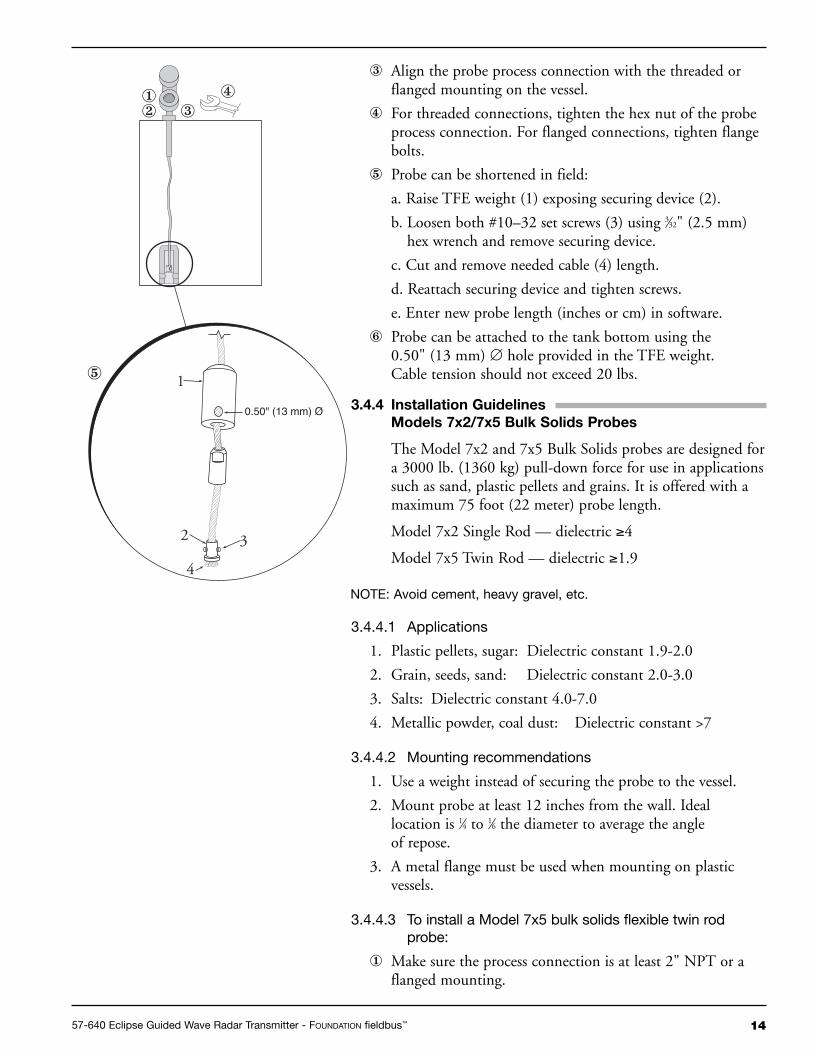
� Probe can be shortened in field:
a. Raise TFE weight (1) exposing securing device (2).
b. Loosen both #10–32 set screws (3) using 3⁄32" (2.5 mm)hex wrench and remove securing device.
c. Cut and remove needed cable (4) length.
d. Reattach securing device and tighten screws.
e. Enter new probe length (inches or cm) in software.
� Probe can be attached to the tank bottom using the0.50" (13 mm) ∅ hole provided in the TFE weight.Cable tension should not exceed 20 lbs.
3.4.4 Installation GuidelinesModels 7x2/7x5 Bulk Solids Probes
The Model 7x2 and 7x5 Bulk Solids probes are designed fora 3000 lb. (1360 kg) pull-down force for use in applicationssuch as sand, plastic pellets and grains. It is offered with amaximum 75 foot (22 meter) probe length.
Model 7x2 Single Rod — dielectric ≥4
Model 7x5 Twin Rod — dielectric ≥1.9
NOTE: Avoid cement, heavy gravel, etc.
3.4.4.1 Applications
1. Plastic pellets, sugar: Dielectric constant 1.9-2.0
2. Grain, seeds, sand: Dielectric constant 2.0-3.0
3. Salts: Dielectric constant 4.0-7.0
4. Metallic powder, coal dust: Dielectric constant >7
3.4.4.2 Mounting recommendations
1. Use a weight instead of securing the probe to the vessel.
2. Mount probe at least 12 inches from the wall. Ideallocation is 1⁄4 to 1⁄6 the diameter to average the angleof repose.
3. A metal flange must be used when mounting on plasticvessels.
3.4.4.3 To install a Model 7x5 bulk solids flexible twin rodprobe:
� Make sure the process connection is at least 2" NPT or aflanged mounting.
1
0.50" (13 mm) Ø
2 3
4
⑤
①② ③
④

15 57-640 Eclipse Guided Wave Radar Transmitter - FOUNDATION fieldbus™
� Make sure that there is at least 1" (25 mm) spacingbetween the active probe rod and any part of the tank(walls, stillwell, pipes, support beams, mixer blades, etc.).Minimum stillwell diameter for Twin Rod probe is 3".
� Carefully place the probe into the vessel. Align the gasketon flanged installations.
� Align the probe process connection with the threaded orflanged mounting on the vessel.
� For threaded connections, tighten the hex nut of the probeprocess connection. For flanged connections, tighten flangebolts.
Refer to Bulk Solid Guidelines, Section 2.4.4.
Probe can be shortened in the field:
� a. Loosen and remove the two cable clamps.
b. Slide the weight off of the probe.
c. Cut the cable to the required length.
d. Remove 12 inches of the rib between the two cables.
e. Strip 6 inches of coating from the two cables.
f. Slide the weight back on to the probe.
g. Reinstall the two cable clamps and tighten.
h. Enter the new probe length (inches or cm) in software.
3.4.4.4 To install a Model 7x2 bulk solids flexible single rodprobe:
� Make sure the process connection is at least 2" NPT or aflanged mounting.
� Carefully place the probe into the vessel. Align the gasketon flanged installations.
� Align the probe process connection with the threaded orflanged mounting on the vessel.
� For threaded connections, tighten the hex nut of the probeprocess connection. For flanged connections, tighten flangebolts.
� Probe can be shortened in field:
� a. Loosen and remove the two cable clamps.
b. Slide the weight off of the probe.
c. Cut the cable to the required length plus 6.38".
d. Slide the weight back on to the probe.
e. Reinstall the two cable clamps and tighten.
f. Enter the new probe length (inches or cm) in software.
Model 7x5 Dual RodBulk Solids Probe
Model 7x2 Single RodBulk Solids Probe
1657-640 Eclipse Guided Wave Radar Transmitter - FOUNDATION fieldbus™
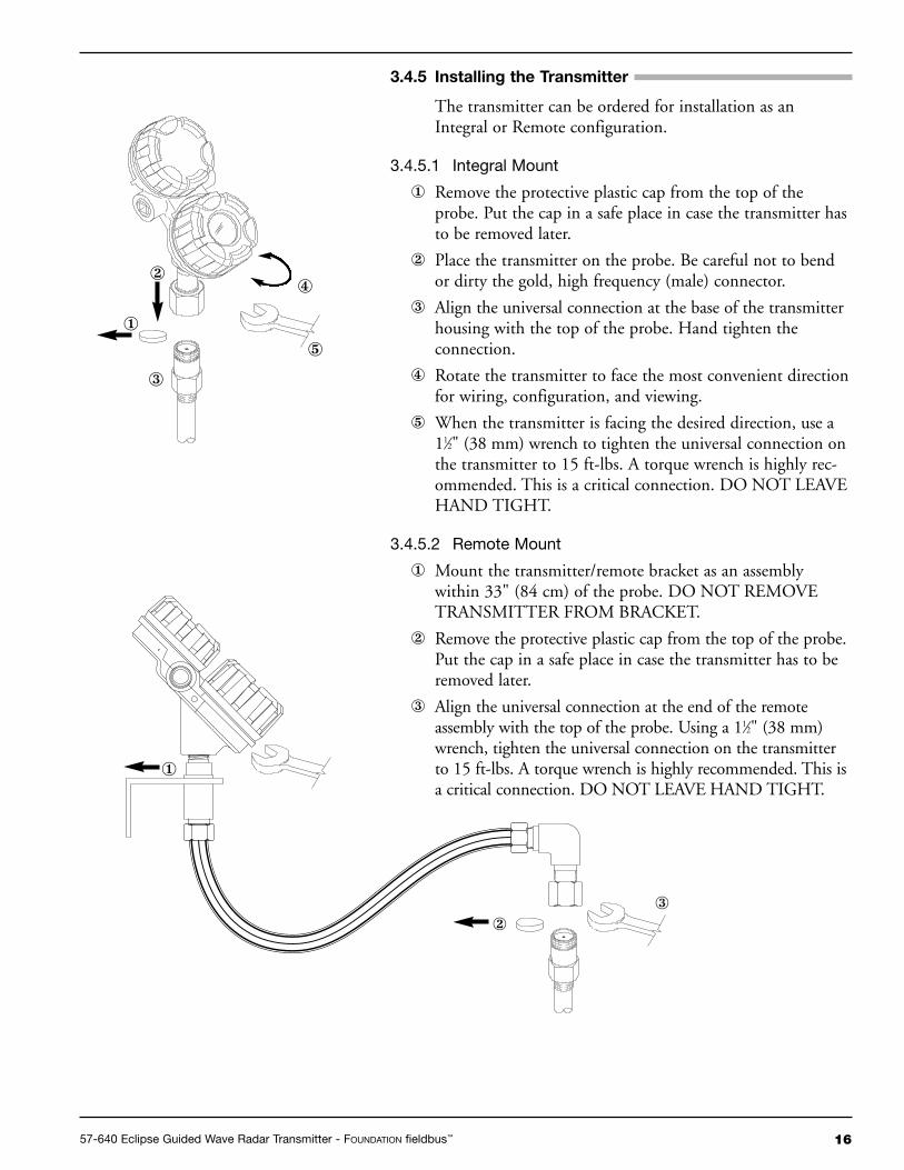
3.4.5 Installing the Transmitter
The transmitter can be ordered for installation as an Integral or Remote configuration.
3.4.5.1 Integral Mount
� Remove the protective plastic cap from the top of theprobe. Put the cap in a safe place in case the transmitter hasto be removed later.
� Place the transmitter on the probe. Be careful not to bendor dirty the gold, high frequency (male) connector.
� Align the universal connection at the base of the transmitterhousing with the top of the probe. Hand tighten theconnection.
� Rotate the transmitter to face the most convenient directionfor wiring, configuration, and viewing.
� When the transmitter is facing the desired direction, use a11⁄2" (38 mm) wrench to tighten the universal connection onthe transmitter to 15 ft-lbs. A torque wrench is highly rec-ommended. This is a critical connection. DO NOT LEAVEHAND TIGHT.
3.4.5.2 Remote Mount
� Mount the transmitter/remote bracket as an assemblywithin 33" (84 cm) of the probe. DO NOT REMOVETRANSMITTER FROM BRACKET.
� Remove the protective plastic cap from the top of the probe.Put the cap in a safe place in case the transmitter has to beremoved later.
� Align the universal connection at the end of the remoteassembly with the top of the probe. Using a 11⁄2" (38 mm)wrench, tighten the universal connection on the transmitterto 15 ft-lbs. A torque wrench is highly recommended. This isa critical connection. DO NOT LEAVE HAND TIGHT.
�
�
�
�
�
�
��
4.0 Function Blocks
4.1 Overview
The Enhanced Eclipse Model 705 Guided Wave RadarLevel Transmitter operates on the principle of Time DomainReflectometry (TDR). Refer to Bulletins 57-101 and 57-600for more detailed information on the Eclipse product family.
The Enhanced Eclipse Model 705FF is a Guided WaveRadar (GWR) level transmitter with six FOUNDATION fieldbus™
Function Blocks (one Resource Block, one TransducerBlock, and four Analog Input blocks. The idea of FunctionBlocks, which a user can customize for a particular applica-tion, is a key concept of Fieldbus topology. Function Blocksconsist of an algorithm, inputs and outputs, and a user-defined name.
The TRANSDUCER block output is available to the net-work through the ANALOG INPUT blocks.
• The ANALOG INPUT blocks (AI) take the TRANSDUCERblock level or volume values and makes them available as ananalog value to other function blocks. The AI blocks havescaling conversion, filtering, and alarm functions.
4.1.1 Universal Fieldbus Block Parameters
The following are general descriptions of the parameterscommon to all blocks. Additional information for a givenparameter is described later in that specific block section.
ST_REV (static data revision): a read only parameter thatgives the revision level of the static data associated with theblock. This parameter will be incremented each time a staticparameter attribute value is written and is a vehicle fortracking changes in static parameter attributes.
TAG_DESC (tag descriptor): a user assigned parameterthat describes the intended application of any given block.
STRATEGY: a user assigned parameter that identifiesgroupings of blocks associated with a given network connec-tion or control scheme.
ALERT_KEY: a user assigned parameter which may be usedin sorting alarms or events generated by a block.
MODE_BLK: a structured parameter composed of theactual mode, the target mode, the permitted mode(s), andthe normal mode of operation of a block.
• The actual mode is set by the block during its execution toreflect the mode used during execution.
• The target mode may be set and monitored through themode parameter.
17 57-640 Eclipse Guided Wave Radar Transmitter - FOUNDATION fieldbus™

• The permitted modes are listed for each block.
• The block must be in an automatic mode for normaloperation.
NOTE: The MODE_BLK target parameter must be OOS (out of service)to change configuration and calibration parameters in that func-tion block (when in OOS, the normal algorithm is no longer exe-cuted and any outstanding alarms are cleared).
All blocks must be in an operating mode for the device to oper-ate. This requires the Resource Block to be in “AUTO” and theTransducer Block to be in “AUTO” before the Function Blockscan be placed in a mode other than OOS (out of service).
BLOCK_ERR: a parameter that reflects the error status ofhardware or software components associated with, anddirectly affecting, the correct operation of a block.
NOTE: A BLOCK_ERR of “Simulation Active” in the Resource Blockdoes not mean simulation is active—it merely indicates that thesimulation (hardware) enabling jumper is present.
4.2 Resource Block
The RESOURCE block contains data specific to theEnhanced Model 705 transmitter, along with someinformation about the firmware.
NOTE: The Resource Block has no control function.
MODE_BLK: Must be in AUTO in order for the remain-ing blocks in the transmitter to operate.
NOTE: A Resource Block in “out of service” will stop all function blockexecution in the transmitter.
RS_STATE (Resource State): identifies the state of theRESOURCE block state machine. Under normal operatingconditions, it should be “On-Line.”
DD_RESOURCE: a string identifying the tag of theresource that contains the Device Description for this device.
MANUFAC_ID: contains Magnetrol International’sFOUNDATION fieldbus™ manufacturer’s ID number, which is0x000156.
DEV_TYPE: the model number of the Enhanced EclipseModel 705 transmitter (0x0001). It is used by interfacedevices to locate the Device Descriptor (DD) file for thisproduct.
DEV_REV: contains the firmware revision of the EnhancedEclipse Model 705 transmitter. It is used by interfacedevices to correctly select the associated DD.
1857-640 Eclipse Guided Wave Radar Transmitter - FOUNDATION fieldbus™

DD_REV: contains the revision of the DD associated withthe version of firmware in the Enhanced Eclipse Model 705transmitter. It is used by interface devices to correctly selectthe associated DD.
RESTART: Default and Processor selections are available.Default will reset the Model 705 to the established blockconfiguration.
NOTE: As RESTART DEFAULT will set all configuration parameters totheir default values. Devices need to be reconfigured followingactivation of this function
FEATURES: a list of the features available in the transmitter.The Model 705 features include Reports, and SoftwareWrite Locking.
FEATURES_SEL: allows the user to turn Features on or off.
CYCLE_TYPE: identifies the block execution methods thatare available.
CYCLE_SEL: allows the user to select the block executionmethod.
MIN_CYCLE_T: the time duration of the shortest cycleinterval. It puts a lower limit on the scheduling of theresource.
NV_CYCLE_T: the minimum time interval between copiesof non-volatile (NV) parameters to NV memory. NV mem-ory is only updated if there has been a significant change inthe dynamic value and the last value saved will be availablefor the restart procedure. A value of “0” means it will neverbe automatically copied. Entries made by human interfacedevices to NV parameters are copied to non-volatile memoryat the time of entry.
NOTE: After completing a large copy, allow several minutes beforeremoving power from the Eclipse Model 705 transmitter toensure that all data has been saved.
FREE_SPACE: shows the amount of available memory forfurther configuration. The value is zero percent in a pre-configured device.
FREE_TIME: the amount of the block processing time thatis free to process additional blocks.
SHED_RCAS: the time duration at which to give up com-puter writes to function block RCas locations. Shed fromRCas will never happen when SHED_RCAS = 0.
SHED_ROUT: the time duration at which to give up com-puter writes to function block ROut locations. Shed fromROut will never happen when SHED_ROUT = 0.
19 57-640 Eclipse Guided Wave Radar Transmitter - FOUNDATION fieldbus™

FAULT_STATE, SET_FSTATE, CLR_FSTATE: these onlyapply to output function blocks. (The Model 705 has nooutput function blocks).
MAX_NOTIFY: the maximum number of alert reports thatthe transmitter can send without getting a confirmation.
The user can set the number low, to control alert flooding,by adjusting the LIM_NOTIFY parameter value.
LIM_NOTIFY: the maximum numbers of unconfirmedalert notify messages allowed. No alerts are reported if setto zero.
CONFIRM_TIME: the time that the transmitter will waitfor confirmation of receipt of a report before trying again.Retry will not occur if CONFIRM_TIME = 0.
WRITE_LOCK: When set to LOCKED, will prevent anyexternal change to the static or non-volatile data base in theFunction Block Application of the transmitter. Block con-nections and calculation results will proceed normally, butthe configuration will be locked.
UPDATE_EVT (Update Event): is an alert generated by awrite to the static data in the block.
BLOCK_ALM (Block Alarm): is used for configuration,hardware, connection, or system problems in the block. Thecause of any specific alert is entered in the subcode field.The first alert to become active will set the Active status inthe Status attribute. As soon as the Unreported status iscleared by the alert reporting task, another block alert maybe reported without clearing the Active status, if the sub-code has changed.
ALARM_SUM (Alarm Summary): contains the currentalert status, the unacknowledged states, the unreportedstates, and the disabled states of the alarms associated withthe block.
ACK_OPTION (Acknowledge Option): selects whetheralarms associated with the block will be automaticallyacknowledged.
WRITE_PRI (Write Priority): the priority of the alarmgenerated by clearing the write lock.
WRITE ALM (Write Alarm): the alert generated if thewrite lock parameter is cleared.
ITK_VER (ITK Version): contains the version of theInteroperability Test Kit (ITK) used by the FieldbusFoundation during their interoperability testing.
2057-640 Eclipse Guided Wave Radar Transmitter - FOUNDATION fieldbus™

4.3 GWR Transducer Block
The GWR TRANSDUCER block is a custom blockcontaining parameters that support the Enhanced EclipseModel 705 level transmitter. It contains the GWR probeconfiguration, diagnostics, and calibration data, and outputslevel with status information.
The TRANSDUCER block parameters are grouped in auseful configuration. There are both read-only parametersand read-write parameters within the TRANSDUCER block.
• The read-only parameters report the block status andoperation modes.
• The read-write parameters affect the function block basicoperation, level transmitter operation, and calibration.
The Transducer Block will automatically be changed to“Out of Service” when the local interface (keypad) is usedto change a parameter online.
4.3.1 GWR Transducer Block Parameters
The first six parameters in the GWR TRANSDUCERblock are the universal parameters discussed in section 4.1.1.The universal parameters are followed by these additionalrequired parameters:
UPDATE_EVT (Update Event): an alert generated by awrite to the static data in the TRANSDUCER block.
Another important parameter found later in the TRANS-DUCER block list is DEVICE_STATUS, which displaysthe status of the device. If more than one message exists,then the messages are displayed in priority order. Refer toSection 8.1.2, Error Messages.
If DEVICE_STATUS indicates a problem, refer toSection 8.1, Troubleshooting (those parameters which areshaded are password-protected).
For a complete list of Transducer Block Parameters, referto table in the Appendix.
4.3.2 Password Parameters
To change a parameter at the local user interface, a valuematching the user password must be entered (Default=1). Ifthe user password is entered, the instrument is in the usermode. After 5 minutes with no keypad activity, the enteredpassword expires.
Factory password is for use by trained factory personnel only.
From the network, the instrument always behaves as if it isin the user mode by default. In other words, it is not neces-sary to enter the user password in order to write parametersfrom the network.
21 57-640 Eclipse Guided Wave Radar Transmitter - FOUNDATION fieldbus™

4.3.3 Eclipse Model 705 Configuration Parameters
This set of parameters within the Transducer Block is impor-tant and required to configure every Eclipse Model 705transmitter.
PROBE_MODEL: Select the choice that corresponds to thefirst four digits of the model number of the probe. An “x”in the selection means that character is variable (the probemodel number is shown on the nameplates attached to boththe transmitter and probe). For example, 7xA-x should bechosen for probe models beginning with 7EA or 7MA.
PROBE_MOUNT: Select the type of mounting on theprobe. The choices are NPT, BSP, and Flange.
MEASUREMENT_TYPE: Select from LEVEL ONLY,LEVEL AND VOLUME, INTERFACE, or INTERFACEAND VOLUME.
PROBE_LENGTH: Enter the exact length of the probe.The probe length is shown as the last three digits of theprobe model number printed on the nameplates attached tothe transmitter and probe. PROBE_LENGTH is shown inSENSOR_UNITs.
LEVEL_OFFSET: Enter the distance from the probe tip tothe desired 0% reference in PROBE_UNITs. The accept-able range is from -24 inches to 600 inches. Refer toSection 4.3.4 for additional information.
DIELECTRIC_RANGE: Select from 10–100, 3–10,1.7–3.0, or 1.7–1.4
NOTE: All dielectric ranges are not available with all probes.
If an unsupported dielectric range is selected, the transmitterwill give a negative response and the value displayed willrevert to its previous value.
THRESHOLD: The threshold can be set as either FIXEDor CFD. The factory default is CFD. This parameter shouldonly be changed to FIXED in those applications measuringtotal level having a lower dielectric material over a higherdielectric material. A typical example for FIXED Thresholdis a hydrocarbon application having water bottoms.
2257-640 Eclipse Guided Wave Radar Transmitter - FOUNDATION fieldbus™
Offset
Probe Length
Probe Mount
0% Set Point
Probe Model
Dielectricof Medium
100% Set Point

23 57-640 Eclipse Guided Wave Radar Transmitter - FOUNDATION fieldbus™
4.3.4 Offset Description
The parameter referred to as LEVEL_OFFSET in theTransducer Block is the desired level reading when liquidsurface is at the end of the probe. The Eclipse transmitter isshipped from the factory with LEVEL_OFFSET set to 0.With this configuration, all measurements are referencedfrom the bottom of the probe. See Example 1.
Example 1 (LEVEL_OFFSET = 0 as shipped from factory): Application calls for a 72-inch NPT Coaxial probe inwater with the bottom of the probe 10 inches above thebottom of the tank. The user wants the 0% point at24 inches and the 100% point at 60 inches as referencedfrom the bottom of the probe.
In those applications in which it is desired to reference allmeasurements from the bottom of the vessel, the value ofLEVEL_OFFSET should be changed to the distancebetween the bottom of the probe and the bottom of thevessel as shown in Example 2.
Example 2:Application calls for a 72-inch NPT coaxial probe inwater with the bottom of the probe 10 inches above thebottom of the tank. The user wants the 0% point at24 inches and the 100% point at 60 inches as referencedfrom the bottom of the tank.
When the Eclipse transmitter is mounted in a chamber/bridle,it is usually desirable to configure the unit with the 0%point at the lower process connection and the 100% pointat the upper process connection. The span is thecenter-to-center dimension. In this case, a negativeLEVEL_OFFSET needs to be entered. In doing so, allmeasurements are then referenced at a point up on theprobe as shown in Example 3.
Example 3:Application calls for a 48-inch cage-coaxial flanged probemeasuring water in a chamber with the bottom of theprobe 6 inches below the lower process connection. Theuser wants the 0% point to be 0 inches at the bottomprocess connection and the 100% point to be 30 inchesat the top process connection.
10"
60"
100%
LCD Menu
0%
24"
PrbModel7xA-x
PrbMountNPT
LvlUnitsin
Probe Ln72 in
Lvl Ofst0.0 in
Dielctrc10-100
Example 1
10"
60"
100%
0%
24"
PrbModel7xA-x
PrbMountNPT
LvlUnitsin
Probe Ln72 in
Lvl Ofst10 in
Dielctrc10-100
LCD Menu
Example 2
6"
30"
0%
100% PrbModel7xR-x
PrbMountFlange
LvlUnitsin
Probe Ln48 in
Lvl Ofst-6.0 in
Dielctrc10-100
LCD Menu
Example 3

4.4 User-Calibration Parameters
One of the main advantages of the Enhanced Eclipse Model705 GWR transmitter is that the device does not need to becalibrated in the field. Every Enhanced Eclipse Model 705transmitter is shipped from the factory precisely calibrated.
On the other hand, part of the advantage ofFOUNDATION fieldbus™ is to provide the ability to monitorchanges and adjustments to a transmitter. The Fieldbus™
concept allows a user to make calibration adjustments ifdeemed necessary.
NOTE: The original factory calibration settings are restored when a newprobe length value is assigned.
It is highly recommended that factory calibration be usedfor optimum performance.
Contact the factory for information on how to perform aUser Calibration.
4.4.1 Factory Parameters
The factory-adjustable calibrated parameters are WINDOW,CONVERSION_FACTOR, and SCALE_OFFSET.
WINDOW is used to adjust for the variations in the analogsection of the Eclipse TDR measurement engine. CON-VERSION_FACTOR and SCALE_OFFSET are the mainfactory calibration settings.
The following parameters are used for either troubleshoot-ing or are parameters adjusted at the factory. They shouldnever be changed in the field.
WINDOW: determines the amount of delay between thegeneration of the transmitted signal pulse and the start ofthe measurement cycle.
FID_TICKS: a measure of the time to the fiducial (refer-ence) pulse.
FID_TICKS_SPREAD: provides an indication of thestability of the FID_TICKS measurement.
LEVEL_TICKS: a measure of the time to the level of theproduct being measured.
LEVEL_TICKS_SPREAD: provides an indication of thestability of the LEVEL_TICKS measurement.
CONVERSION_FACTOR: the slope of the factory-setcalibration line.
SCALE_OFFSET: the intercept of the calibration line.
2457-640 Eclipse Guided Wave Radar Transmitter - FOUNDATION fieldbus™

4.4.2 Firmware Version
The last parameter in the TRANSDUCER block gives thefirmware version of the transmitter.
FIRMWARE_VERSION: displays the version of thefirmware.
NOTE: The user should compare the DD file and revision number of thedevice with the HOST system to ensure they are at the samerevision level.
4.5 Analog Input Block
The ANALOG INPUT (AI) block takes the manufacturer’sinput data, selected by channel number, and makes it avail-able to other function blocks at its output:
1. Level
2. Volume
3. Interface
4. Interface Volume
4.5.1 AI Block Parameters
PV: Either the primary analog value for use in executing thefunction, or a process value associated with it.
OUT: The primary analog value calculated as a result ofexecuting the function block.
SIMULATE: Allows the transducer analog input or outputto the block to be manually supplied when simulate isenabled. When simulate is disabled, the simulate value andstatus track the actual value and status
XD_SCALE: The high and low scale values, engineeringunits code, and number of digits to the right of the decimalpoint used with the value obtained from the transducer fora specified channel.
OUT_SCALE: The high and low scale values, engineeringunits code, and number of digits to the right of the decimalpoint to be used in displaying the OUT parameter.
GRANT_DENY: Options for controlling access of hostcomputers and local control panels to operating, tuning,and alarm parameters of the block.
IO_OPTS: Option which the user may select to alter inputand output block processing.
STATUS_OPTS: Options which the user may select in theblock processing of status.
25 57-640 Eclipse Guided Wave Radar Transmitter - FOUNDATION fieldbus™
Offset
Probe Length
XD
_RA
NG
E "
EU
@10
0%"
XD
_RA
NG
E"E
U@
0%"
Probe Mount
0% Set Point
Probe Model
Dielectricof Medium
100% Set Point
Scaling

CHANNEL: The number of the logical hardware channelthat is connected to this I/O block. This informationdefines the transducer to be used going to or from thephysical world.
L_TYPE: Determines if the values passed by the transducerblock to the AI block may be used directly (Direct) or if thevalue is in different units and must be converted linearly(Indirect), or with square root (Ind Sqr Root), using theinput range defined for the transducer and the associatedoutput range.
LOW_CUT: Limit used in square root processing.
PV_FTIME: Time constant of a single exponential filter forthe PV, in seconds.
FIELD_VAL: Raw value of the field device in % of PVrange, with a status reflecting the Transducer condition,before signal characterization (L_TYPE) or filtering(PV_FTIME).
UPDATE_EVT: This alert is generated by any change tothe static data.
BLOCK_ALM: The block alarm is used for all configuration,hardware, connection failure or system problems in the block.
ALARM_SUM: The current alert status, unacknowledgedstates, unreported states, and disabled states of the alarmsassociated with the function block.
ACK_OPTION: Selection of whether alarms associatedwith the function block will be automatically acknowledged.
ALARM_HYS: Amount the PV must return within thealarm limits before the alarm condition clears. Alarm hys-teresis expressed as a percent of the span of the PV.
HI_HI_PRI: Priority of the high high alarm.
HI_HI_LIM: The setting for high high alarm inengineering units.
HI_PRI: Priority of the high alarm.
HI_LIM: The setting for high alarm in engineering units
LO_PRI: Priority of the low alarm.
LO_LIM: The setting for low alarm in engineering units.
LO_LO_PRI: Priority of the low low alarm.
LO_LO_LIM: The setting for low low alarm in engineeringunits.
HI_HI_ALM: The status for high high alarm and itsassociated time stamp.
2657-640 Eclipse Guided Wave Radar Transmitter - FOUNDATION fieldbus™

HI_ALM: The status for high alarm and its associatedtime stamp.
LO_ALM: The status for low alarm and its associatedtime stamp.
LO_LO_ALM: The status for low low alarm and itsassociated time stamp.
The TRANSDUCER and AI block’s MODE_BLK parame-ter must be set to AUTO to pass the PV Value through theAI to the network.
Transducer scaling, called XD_SCALE, is applied to thePV from the CHANNEL to produce the FIELD_VAL inpercent. Valid XD_SCALE in engineering units is limitedto the five allowable codes of meters (m), centimeters (cm),feet (ft), inches (in), and percent (%) for the Level channels,or gallons, liters, % for the volume channels.
The AI can have a BLOCK_ERR when:
1. Channel is not set correctly.
2. XD_SCALE does not have suitable engineering units or hasrange incompatibility.
3. SIMULATE parameter is active
4. AI block MODE is O/S (out of service).
NOTE: This can be caused by the Resource Block being OOS or the AIBlock not scheduled for execution.
5. L-TYPE not set or set to Direct with improperOUT_SCALE.
The AI uses the STATUS_OPTS setting and the TRANS-DUCER PV LIMIT value to modify the AI PV and OUTQUALITY.
Damping Filter is a feature of the AI block. PV_FTIMEparameter is time constant of a single exponential filter forthe PV, in seconds. This parameter can be used to dampenout fluctuation in level due to excessive turbulence.
The AI block has multiple ALARM functions that monitorthe OUT parameter for out of bound conditions.
27 57-640 Eclipse Guided Wave Radar Transmitter - FOUNDATION fieldbus™

6.0 Diagnostic Parameters
The Eclipse Model 705 GWR measurement engine runsthrough a series of self-tests and will detect and reportfaulty operation. The GWR TRANSDUCER BLOCKdisplays these faults in the DEVICE_STATUS parameter.Refer to Section 8.1.2 for more information on specificfaults and warnings.
BLOCK_ERROR is not used except for indicating Out ofService (OOS).
When the Model 705 transmitter is initially powered on,the measurement engine does not have enough valid meas-urement cycles to make a decision about the output level.For the first sixteen measurement cycles after power isapplied, the QUALITY is “Uncertain,” the SUB_STATUSis “Initial value,” and the LIMIT attribute is “Constant.”
When the Model 705 is operating correctly, the QUALITYis shown as “GOOD,” and the SUB_STATUS is “Non-Specific.”
While changing the transmitter operational parametersusing the local display or through the system configurationtool (with the MODE_BLK in OOS), the output might beinaccurate because of the changing parameters. When thedevice is in a mode where operational parameters can bechanged, the GWR TRANSDUCER BLOCK will stilloutput level but the QUALITY will be shown as “Bad”and the SUB_STATUS is “Out of Service.”
When the Enhanced Model 705 measurement cycle fails tofind a valid output level, the transmitter maintains the lastgood value as the output and flags the failure. The LIMITattribute is the same as the last good measurement. Excessivedisrupted cycles causes the transmitter to go into a definedoperational mode based on the cause of the disrupted cycles.
When the Enhanced Model 705 detects a level above thehighest measurement point of the probe the operationalmode is shown as “May Be Flooded.” This is due to the factthat, since the actual level location above the top of someprobes is not known, the output may not be accurate.
The Model 705 operational mode is DRY_PROBE whenthe level is below the end of the probe. Again, the outputmay not be accurate, since the location of the level belowthe end of the probe is not known. The GWR TRANS-DUCER BLOCK output is calculated as LEVEL_OFFSET.
When in the dry probe condition, the Model 705 comparesthe measured length of the probe to the value entered intothe PROBE_LENGTH parameter. If the measured value
2857-640 Eclipse Guided Wave Radar Transmitter - FOUNDATION fieldbus™

does not match PROBE_LENGTH, a fault is reported. TheQUALITY will be shown as “Bad,” and the SUB_STATUSis “Configuration error.”
If the Model 705 fails to find a measurable level, either dueto an actual loss of a level signal or the loss of a properFiducial (reference) signal, the GWR TRANSDUCERBLOCK maintains the last good value as the output andflags the failure. The QUALITY is “Bad,” the SUB_STA-TUS is “Sensor failure” for no level (or “Device failure” forloss of the Fiducial), and the LIMIT attribute is “Constant.”
6.1 Simulation Feature
The Eclipse Model 705 with FOUNDATION fieldbus™ sup-ports the Simulate feature in the Analog Input block. TheSimulate feature is typically used to exercise the operation ofan AI block by simulating a TRANSDUCER block input.
This feature can not be activated without the placement of ahardware jumper. This jumper is installed as standard onthe Eclipse Model 705, and is placed in an inconvenientlocation to avoid inadvertent disabling of this feature.
NOTE: A BLOCK_ERR of “Simulation Active” in the Resource Blockdoes not mean simulation is active—it merely indicates that thesimulation (hardware) enabling jumper is present.
Contact the factory for instructions on how to remove thisjumper and permanently disable the Simulate feature.
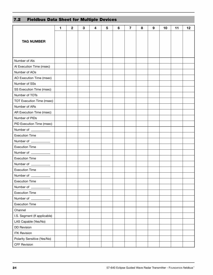
7.0 Documentation
The following two tables are examples of data sheetsdescribing what information is need to fully specify aFieldbus device. The first table shows one device per page,while table 2 is intended for multiple devices.
Refer to “FOUNDATION fieldbus™ System EngineeringGuidelines—AG-181” for additional information. Thisdocument can be found at www.fieldbus.org.
29 57-640 Eclipse Guided Wave Radar Transmitter - FOUNDATION fieldbus™

3057-640 Eclipse Guided Wave Radar Transmitter - FOUNDATION fieldbus™
Fieldbus Function Blocks Segment Information Miscellaneous Information
Analog Input (AI)Number
Execution Time (msec)
Arithmetic (A)Execution Time (msec)
Digital Alarm (DA)Execution Time (msec)
Device:
Segment #
LAS Capable: YES NO
Device current draw (mA):
In-rush current (mA):
Device Lift-off (minimum) voltage:
Device capacitance:
Polarity Sensitive: YES NO
DD Revision:
CFF Revision: Tested with ITKrevision
NOTES:
Discrete Input (DI)Number
Execution Time (msec)
CalculateExecution Time (msec)
Analog Alarm (AA)Execution Time (msec)
Bias/Gain Settings (BG)Execution Time (msec)
Deadtime (D)Execution Time (msec)
Manual LoaderExecution Time (msec)
Complex Analog Output (CAO)Execution Time (msec)
Proportional/Integral/Derivative(PID)
Execution Time (msec)
Step Output PID (SOPID)Execution Time (msec)
Analog Output (AO)Number
Execution Time (msec)
Set Point Ramp GeneratorExecution Time (msec)
Discrete Output (DO)Number
Execution Time (msec)
Signal Characterizer (SC)Execution Time (msec)
Control Selector (CS)Execution Time (msec)
Digital Human Interface (DHI)Execution Time (msec)
Proportional/Derivative (PD)Execution Time (msec)
Execution Time (msec)
RatioNumber
Execution Time (msec)
7.1 Fieldbus Data Sheet for Individual Instrument
31 57-640 Eclipse Guided Wave Radar Transmitter - FOUNDATION fieldbus™
7.2 Fieldbus Data Sheet for Multiple Devices
TAG NUMBER
1 2 3 4 5 6 7 8 9 10 11 12
Number of AIs
AI Execution Time (msec)
Number of AOs
AO Execution Time (msec)
Number of SSs
SS Execution Time (msec)
Number of TOTs
TOT Execution Time (msec)
Number of ARs
AR Execution Time (msec)
Number of PIDs
PID Execution Time (msec)
Number of
Execution Time
Number of
Execution Time
Number of
Execution Time
Number of
Execution Time
Number of
Execution Time
Number of
Execution Time
Number of
Execution Time
Channel
I.S. Segment (If applicable)
LAS Capable (Yes/No)
DD Revision
ITK Revision
Polarity Sensitive (Yes/No)
CFF Revision

3257-640 Eclipse Guided Wave Radar Transmitter - FOUNDATION fieldbus™
LEVEL and % OUTPUT values Basic configuration data is Reconfigure the Probe Model and/or Probeare inaccurate. questionable. Mount, Probe Length or Level Offset.
1) Ensure the Level is accurate.2) Verify EU0% and EU100% Loop values.
Interface level has significant emulsion. Examine process to reduce/eliminateemulsion layer.
LEVEL readings are repeatable but Configuration data does not Ensure proper Probe Model and probe length.consistently high or low from actual accurately match probe lengthby a fixed amount. or tank height. Adjust trim level value by the amount of
noted inaccuracy.
LEVEL and % OUTPUT values Turbulence Increase the Damping factor until thefluctuate. readings stabilize.
High Frequency connection Check Fid Spread (should be stable within±10 counts).
LEVEL and % OUTPUT values Lower dielectric material over higher Select Fixed Threshold option. all reading low vs. actual. dielectric material, e.g., oil over water
Coating, clumping or buildup on probe These may be expected inaccuracies dueto affect on pulse propagation.
Dense, water based foam These may be expected inaccuracies due to affect on pulse propagation.
Level Reading on Display is stuck at Software believes probe is flooded Check actual level. If probe is not flooded,full scale. (level near very top of probe). Check for buildup or obstructions near top
of probe. Select higher dielectric range.Check for condensation in probeconnection. Add Blocking Distance.
LEVEL and % OUTPUT values Possible configuration issue 1) Increase Blocking Distancevalues all at maximum level. with single rod probe 2) Increase Dielectric Range
LEVEL and % OUTPUT values Possible obstruction in tank 1) Increase Dielectric Range until reading high vs. actual. affecting single rod probe obstruction is ignored
2) Relocate probe away from obstruction
LEVEL value reading high when Transmitter loose or disconnected Ensure transmitter connected securelyshould be zero. from probe to probe.
Symptom Problem Solution
8.1.1 Troubleshooting System Problems
NOTE: When consulting the factory concerning improper operation, use proper tables on Pages 65-67. Enter all data when transmitteris working CORRECTLY or INCORRECTLY.
8.0 Reference Information
8.1 Troubleshooting
The Eclipse transmitter is designed and engineered fortrouble-free operation over a wide range of operatingconditions. Common transmitter problems are discussedin terms of their symptoms and recommended correctiveactions. Information on how to handle material buildupon the probe is also provided in this section.
WARNING!Explosion hazard. Do not connect ordisconnect equipment unless powerhas been switched off or the area isknown to be non-hazardous.

33 57-640 Eclipse Guided Wave Radar Transmitter - FOUNDATION fieldbus™
8.1.2 Error Messages
Display Message Description Comment
OK None Normal operating mode
Initial None Program is Initializing. This is a transient condition.
DryProbe None Normal message for a dry probe. End of probe signal is being detected.
EOP Low End of Probe signal from a dryprobe is out of range
1) Ensure probe length is entered correctly
2) Set transmitter to a lower dielectric range
3) Consult factory
EOP High End of Probe signal is out ofrange
1) Ensure probe length is entered correctly
2) Consult factory
WeakSgnl None. Signal amplitude is lowerthan desired.
1) Set transmitter to lower dielectric range
2) Increase sensitivity
Flooded? Loss of level signal possiblydue to flooding, twin rodprobes only
1) Decrease level in vessel
2) Set transmitter to lower dielectric range
3) Replace with Model 7xR Overfill probe
NoSignal No level signal being detected. 1) Ensure dielectric setting is correct for measured medium
2) Increase sensitivity
3) Confirm that the probe type is proper for the dielectric of the medium
4) Consult factory
No Fid Fiducial signal is not beingdetected
1) Check connection between probe and transmitter
2) Check for moisture on top of probe
3) Check for damaged gold pin on the high frequency connector
4) Consult factory
FidShift FidTicks shifted from expectedvalue
1) Check connection between probe and transmitter
2) Check for moisture on top of probe
3) Check for damaged gold pin on the high frequency connector
4) Consult factory
SZ Alarm Safety Zone alarm has beentripped
Decrease level in vessel
Hi Temp Present temperature inelectronics compartment isabove +80° C
1) Transmitter may need to be moved to ensure ambient temperatureis within specification
2) Change to remote mount transmitter

3457-640 Eclipse Guided Wave Radar Transmitter - FOUNDATION fieldbus™
8.1.2 Error Messages
Display Message Description Comment
Lo Temp Present temperature inelectronics compartment isbelow -40° C.
1) Transmitter may need to be moved to ensure ambient temperatureis within specification
2) Change to remote mount transmitter
HiVolAlm Level more than 5% abovehighest point in strapping table.
Verify strapping table is entered correctly.None. Signal amplitude islower than desired.
Sys Warn Unexpected but non-fatalsoftware event
Consult factory
Default Cal Factory set default calibrationparameters are in use, levelreading may be inaccurate
Consult factory
SlopeErr Ramp circuit generatingimproper voltage
Consult factory
No Ramp No End-of-Ramp signal detected Consult factory
Default Params Internal non-volatile parametershave been defaulted
Consult factory

35 57-640 Eclipse Guided Wave Radar Transmitter - FOUNDATION fieldbus™
8.1.3 FF Segment Checklist
There can be several reasons for a FOUNDATION fieldbus™
installation to be in a faulty condition. In order to assurethat communication can be established, the followingrequirements must be met.
• Device supply voltage must be higher than 9 VDC with amaximum of 32 VDC.
• Total current draw of a given segment cannot exceed therating shown on the power conditioner and/or barrier.
• Device polarity must be correct.
• Two 100 Ω, 1 µF terminators must be connected to thenetwork—one at each end of the segment.
• Cable length plus spur length must not exceed the followingvalues:
• The cable shield is to be hard grounded only at one pointclose to the DCS. In addition, the cable shield can becapacitively grounded in multiple places to improve EMCprotection.
• Ensure all devices are on the “live list,” and the schedule hasbeen downloaded.
• Ensure the device identity is in the Resource Block.
• Ensure that the Resource Block, then the Transducer Block,and lastly the Function Block(s) are in“Auto” mode ratherthan Out of Service (OOS).
If all of these requirements are met, a stable communicationshould be established.
Number of Spurs 1 Device 2 Devices 3 Devices 4 Devices
25–32 — — — —
19–24 100 ft. (30 m) — — —
15–18 200 ft. (60 m) 100 ft. (30 m) — —
13–14 300 ft. (90 m) 200 ft. (60 m) 100 ft. (30 m) —
1–12 400 ft. (120 m) 300 ft. (90 m) 200 ft. (60 m) 100 ft. (30 m)
Pair Shield Twisted Size Length Type
Single Yes Yes AWG 18 (0.8 mm2) 6,200 ft. (1,900 m) A
Multi Yes Yes AWG 22 (0.32 mm2) 3,900 ft. (1,200 m) B
Multi No Yes AWG 26 (0.13 mm2) 1,300 ft. (400 m) C
Multi Yes No AWG 16 (1.25 mm2) 650 ft. (200 m) D
TEXT HERE............
3657-640 Eclipse Guided Wave Radar Transmitter - FOUNDATION fieldbus™
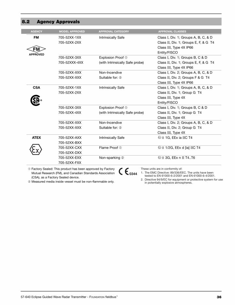
8.2 Agency Approvals
FM 705-52XX-1XX Intrinsically Safe Class I, Div. 1; Groups A, B, C, & D705-52XX-2XX Class II, Div. 1; Groups E, F, & G T4
Class III, Type 4X IP66Entity/FISCO
705-52XX-3XX Explosion Proof � Class I, Div. 1; Groups B, C & D 705-52XXX-4XX (with Intrinsically Safe probe) Class II, Div. 1; Groups E, F, & G T4
Class III, Type 4X IP66705-52XX-XXX Non-Incendive Class I, Div. 2; Groups A, B, C, & D705-52XX-XXX Suitable for: � Class II, Div. 2; Groups F & G T4
Class III, Type 4X IP66CSA 705-52XX-1XX Intrinsically Safe Class I, Div. 1; Groups A, B, C, & D
705-52XX-2XX Class II, Div. 1; Group G T4Class III, Type 4XEntity/FISCO
705-52XX-3XX Explosion Proof � Class I, Div. 1; Groups B, C & D705-52XX-4XX (with Intrinsically Safe probe) Class II, Div. 1; Group G T4
Class III, Type 4X705-52XX-XXX Non-Incendive Class I, Div. 2; Groups A, B, C, & D705-52XX-XXX Suitable for: � Class II, Div. 2; Group G T4
Class III, Type 4XATEX 705-52XX-AXX Intrinsically Safe II 1G, EEx ia IIC T4
705-52XX-BXX705-52XX-CXX Flame Proof � II 1/2G, EEx d [ia] IIC T4705-52XX-DXX705-52XX-EXX Non-sparking � II 3G, EEx n II T4..T6705-52XX-FXX
AGENCY MODEL APPROVED APPROVAL CATEGORY APPROVAL CLASSES
� Factory Sealed: This product has been approved by FactoryMutual Research (FM), and Canadian Standards Association(CSA), as a Factory Sealed device.
� Measured media inside vessel must be non-flammable only.
These units are in conformity of:1. The EMC Directive: 89/336/EEC. The units have been tested to EN 61000-6-2/2001 and EN 61000-6-4/2001.2. Directive 94/9/EC for equipment or protective system for use in potentially explosive atmospheres.
0344
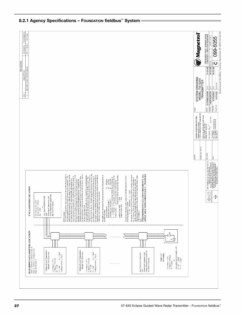
37 57-640 Eclipse Guided Wave Radar Transmitter - FOUNDATION fieldbus™
8.2.1 Agency Specifications – FOUNDATION fieldbus™ System

3857-640 Eclipse Guided Wave Radar Transmitter - FOUNDATION fieldbus™
8.3 Specifications
8.3.1 Functional
System Design
Measurement Principle Guided time-of-flight via time domain reflectometry
Input
Measured Variable Level, determined by the time-of-flight of a guided radar pulse from
transmitter to product surface and back
Zero and Span 6 inches to 75 feet (15 to 2286 cm)
User Interface
Keypad 3-button menu-driven data entry and system security
Indication 2-line × 8-character display
Digital Communication FOUNDATION fieldbus™, H1 (31.25 kbits/sec)
Interoperability test kit (ITK Revision) ITK 4.61
LAS capable Yes, Device type: Linkmaster
Minimum Operating Voltage 9 VDC
Quiescent Current Draw 17 mA
DEV Revision 0X01
Function Blocks AI_1, AI_2, AI_3, AI_4
Damping Adjustable 0-10 seconds
Power (Measured at instrument terminals)
Fieldbus General Purpose/Explosion Proof 9 to 32 VDC (17 mA maximum current draw)
IS/FISCO/FNICO 9–32 VDC (17 mA maximum current draw)
Housing
Material Aluminum A356T6 (<0.20% copper), optional 316 stainless steel
Cable Entry 3⁄4" NPT and M20

39 57-640 Eclipse Guided Wave Radar Transmitter - FOUNDATION fieldbus™
Reference Conditions � Reflection from water at +70° F (+20° C) with 72" coaxial probe
(CFD threshold)
Linearity Coaxial/Twin Rod Probes: <0.1% of probe length or 0.1 inch (whichever is greater)
Single Rod Probes: <0.3% of probe length or 0.3 inch (whichever is greater)
Measured Error Coaxial/Twin Rod Probes: ±0.1% probe length or 0.1 inch (whichever is greater)
Single Rod Probes ±0.5% probe length or 0.5 inch (whichever is greater)
Resolution ±0.1 inch
Repeatability <0.1 inch
Hysteresis <0.1 inch
Response Time <1 second
Warm-up Time <5 seconds
Operating Temp. Range -40° to +175° F (-40° to +80° C)
LCD Temp. Range -5° to +160° F (-20° to +70° C)
Ambient Temp. Effect Approximately +0.02% of probe length/ ° C
Process Dielectric Effect <0.3 inch within selected range
Humidity 0-99%, non-condensing
Electromagnetic Compatibility Meets CE requirements (EN-61000-6-2/2001, 61000-6-4/2001)
(Twin and Single Rod probes must be used in metallic vessel or
stillwell to maintain CE requirement)
8.3.2 Performance - Model 705
� Specifications will degrade with Model 7xB, 7xD, and 7xP probes and/or Fixed threshold configuration.
Top 24 inches of Model 7xB probe: 1.2 inches (30 mm). Specification for top 48 inches of single rod willbe application dependent.
Environment
Operating Temperature -40 to +175° F (-40 to +80° C)
Display Function Operating Temperature -5 to +160° F (-20 to +70° C)
Storage Temperature -50 to +175° F (-40 to +80° C)
Humidity 0-99%, non-condensing
Electromagnetic Compatibility Meets CE Requirements: EN 50081-2, EN 50082-2
Note: Twin Rod and Single Rod probes must be used in metallic vessel
or stillwell to maintain CE requirement.
Mounting Affects: Twin Rod Active rod must be mounted at least 1" (25 mm) from any surface or
obstruction. Minimum stillwell diameter for Twin Rod probe is 3".
Single Rod Nozzles do not restrict performance by ensuring the following:
No nozzle is <2" (50 mm) diameter
Ratio of Diameter: Length is 1:1 or greater;
any ratio <1:1 (e.g., a 2" × 6" nozzle = 1:3) may require a Blocking
Distance and/or DIELECTRIC adjustment (see Section 2.6.5)
No pipe reducers are used
Obstructions (See Probe Clearance Table, page 44)
Keep conductive objects away from probe to ensure proper performance
Shock Class ANSI/ISA-S71.03 Class SA1
Vibration Class ANSI/ISA-S71.03 Class VC2

4057-640 Eclipse Guided Wave Radar Transmitter - FOUNDATION fieldbus™
8.3.3 Performance - Model 705 Interface
Reference Conditions Reflection from liquid of selected dielectric at +70° F (+20° C) with 72" probe
Linearity <0.5 inch
Measured Error Upper layer ±1 inch
Interface layer ±1 inch (clean distinct interface required)
Upper Layer Dielectric 1.4–5.0
Interface Layer Dielectric >15
Resolution ±0.1 inch
Repeatability <0.5 inch
Hysteresis <0.5 inch
Response Time <1 second
Warm-up Time <5 seconds
Operating Temp. Range -40° to +175° F (-40° to +80° C)
LCD Temp. Range -5° to +160° F (-20° to +70° C)
Ambient Temp. Effect Approximately ±0.02% of probe length/ ° C
Humidity 0-99%, non-condensing
Electromagnetic Compatibility Meets CE requirements (EN-61000-6-2/2001, EN 61000-6-4/2001)

41 57-640 Eclipse Guided Wave Radar Transmitter - FOUNDATION fieldbus™
8.4 Parts
8.4.1 Replacement PartsItem Description Part Number
� Electronic moduleFOUNDATION fieldbus™ 031-2836-001
� Terminal boardFOUNDATION fieldbus™ 030-9151-003
� O-ring (neoprene) 012-2201-237(Consult Factory for alternative O-ring materials)
� Housing cover without glass 004-9193-003
� Housing cover with glass (GP, IS) 036-4410-001(XP) 036-4410-003
8.4.2 Recommended Spare PartsItem Description Part Number
� Electronic moduleFOUNDATION fieldbus™ 031-2836-001
� Terminal boardFOUNDATION fieldbus™ 030-9151-003

4257-640 Eclipse Guided Wave Radar Transmitter - FOUNDATION fieldbus™
8.5 Model Numbers
8.5.1 Transmitter
0 None
0 3⁄4" NPT1 M20
1 Cast aluminum, dual compartment, 45° angle2 316 stainless steel, dual compartment, 45° angle
1Integral, General Purpose & Intrinsically Safe (FM & CSA), Non-incendive (Class I, Div. 2)
2Remote, General Purpose & Intrinsically Safe (FM & CSA), Non-incendive (Class I, Div. 2)
3 Integral, Explosion Proof (FM & CSA)4 Remote, Explosion Proof (FM & CSA)
AIntegral, General Purpose & Intrinsically Safe(ATEX & JIS EEx ia IIC T4)
BRemote, General Purpose & Intrinsically Safe(ATEX & JIS EEx ia IIC T4)
CIntegral, Explosion Proof (ATEX EEx d ia IIC T4)(must be ordered with Conduit Connection Codes 0 and 1)
DRemote, Explosion Proof (ATEX EEx d ia IIB T4)(must be ordered with Conduit Connection Codes 0 and 1)
E Integral, Non-incendive (ATEX EEx n IIC T6) (Model 705 only)F Remote, Non-incendive (ATEX EEx n IIC T6) (Model 705 only)
0 No digital display and keypadA Digital display and keypad
1 4-20 mA with HART2 FOUNDATION fieldbus™ Digital Communications (English only)
SIGNAL OUTPUT
7 0 5 5
705 Eclipse Guided Wave Radar Level Transmitter
5 24 VDC, Two-wire
BASIC MODEL NUMBER
POWER
ACCESSORIES
CONDUIT CONNECTION
MOUNTING/CLASSIFICATION
HOUSING
OPTIONS

43 57-640 Eclipse Guided Wave Radar Transmitter - FOUNDATION fieldbus™
8.5.2 Probe
7
Refer to pages 44 and 45 for selections
24" to 240" (60 cm to 610 cm) (7xS only: 180" (457 cm) maximum)(unit of measure is determined by second digit of Model Number)Examples: 24 inches = 024; 60 centimeters = 060
0 Viton® GFLT1 EPDM (Ethylene Propylene Rubber)2 Kalrez 40798 Aegis PF128N None (Use with probes 7xD, 7xP, 7xF-E, 7xF-F, 7xF-P)
A 316/316L stainless steelB Hastelloy C, Configuration/Style codes A, B, F and R onlyC Monel, Configuration/Style codes A, B, F and R only
ESanitary, 316/316L stainless steel (20 Ra finish), Configuration/Style code F only, Process connections codes 4P, 5P, and 6P only
F PFA faced flange, 2" to 4", 150# to 300#, Configuration/Style code F only,Process connection codes 43, 44, 53, 54, 63, 64, DA, DB, EA, EB, FA, and FB only
K 316/316L stainless steel probe and process connection, ASME B31.1 specifications (model 7xS only)
P Paint Probe, 316/316L SS, 3⁄4" process connection or largerConfiguration/Style code F only: maximum length 72"
4 PFA insulated rod, 2" NPT process connection or larger, Configuration/Style code F only
MATERIAL OF CONSTRUCTION
7E Eclipse GWR probe, English unit of measure7M Eclipse GWR probe, Metric unit of measure
PROCESS CONNECTION SIZE/TYPE
BASIC MODEL NUMBER
CONFIGURATION/STYLE
O-RINGS
LENGTH – PROBE MODELS 7xA, 7xB, 7xD, 7xF, 7XJ, 7xP, 7xR & 7xS
LENGTH – PROBE MODEL 7x1, 7x2, 7x5 & 7x73' to 75' (1 to 22 m) – (7x2, 7x5 & 7x7 only: 5' (1.5 m) minimum)(unit of measure is determined by second digit of Model Number)Examples: 30 feet = 030; 10 meters = 010
A Coaxial, 3⁄4" process connection or larger (Dielectric range ≥1.4)B Twin Rod, 2" NPT or 3" flanged process connection or larger (Dielectric range ≥1.9)D Coaxial, High Temperature/High Pressure, 3⁄4" process conn. or larger (Dielectric range ≥1.4)F Single Rod, Rigid, 2" process connection or larger (Dielectric range ≥1.9)J Single Rod, Rigid, High Temperature/High Pressure (Dielectric range ≥ 1.9)P Coaxial, High Pressure, 3⁄4" process connection or larger (Dielectric range ≥1.4)R Coaxial, Overfill, 3⁄4" process connection or larger (Dielectric range ≥1.4)S Coaxial, Hot Water/Steam, 3⁄4" process connection or larger (Dielectric range ≥10)1 Single Rod, Flexible, 2" process connection or larger (Dielectric range ≥1.9)2 Single Rod, Flexible Bulk Solid, 2" process connection or larger (Dielectric range ≥4.0)5 Twin Rod, Flexible Bulk Solid, 2" process connection or larger (Dielectric range ≥1.9)7 Twin Rod Flexible, 2" NPT or 3" flanged process connection or larger (Dielectric range 1.9–10)

4457-640 Eclipse Guided Wave Radar Transmitter - FOUNDATION fieldbus™
8.5.2 Probe
Insertion LengthNPT Process Connection
Insertion LengthBSP Process Connection
Insertion LengthANSI or DIN Welded Flange
Insertion LengthSanitary Flange
7
5L 3" 900# ANSI Ring Joint Flange �5M 3" 1500# ANSI Ring Joint Flange �5N 3" 2500# ANSI Ring Joint Flange �6K 4" 600# ANSI Ring Joint Flange �6L 4" 900# ANSI Ring Joint Flange �6M 4" 1500# ANSI Ring Joint Flange �6N 4" 2500# ANSI Ring Joint Flange �
48 2" 2500# ANSI Raised Face Flange �53 3" 150# ANSI Raised Face Flange54 3" 300# ANSI Raised Face Flange55 3" 600# ANSI Raised Face Flange �56 3" 900# ANSI Raised Face Flange �57 3" 1500# ANSI Raised Face Flange �58 3" 2500# ANSI Raised Face Flange �63 4" 150# ANSI Raised Face Flange64 4" 300# ANSI Raised Face Flange65 4" 600# ANSI Raised Face Flange �66 4" 900# ANSI Raised Face Flange �67 4" 1500# ANSI Raised Face Flange �68 4" 2500# ANSI Raised Face Flange �
23 1" 150# ANSI Raised Face Flange �24 1" 300# ANSI Raised Face Flange �25 1" 600# ANSI Raised Face Flange �27 1" 900/1500# ANSI Raised Face Flange �28 1'' 2500# ANSI Raised Face Flange �
33 11⁄2" 150# ANSI Raised Face Flange �34 11⁄2" 300# ANSI Raised Face Flange �35 11⁄2" 600# ANSI Raised Face Flange �37 11⁄2" 900/1500# ANSI Raised Face Flange �38 11⁄2" 2500# ANSI Raised Face Flange �43 2" 150# ANSI Raised Face Flange �44 2" 300# ANSI Raised Face Flange �45 2" 600# ANSI Raised Face Flange �47 2" 900/1500# ANSI Raised Face Flange �
3K 11⁄2" 600# ANSI Ring Joint Flange �3M 11⁄2" 900/1500# ANSI Ring Joint Flange �3N 11⁄2" 2500# ANSI Ring Joint Flange �4K 2" 600# ANSI Ring Joint Flange �4M 2" 900/1500# ANSI Ring Joint Flange �4N 2" 2500# ANSI Ring Joint Flange �5K 3" 600# ANSI Ring Joint Flange �
PROCESS CONNECTION SIZE/TYPE
THREADED CONNECTIONS
ANSI RAISED FACE FLANGE CONNECTIONS
ANSI RING JOINT FLANGE CONNECTIONS
� Configuration/Style Codes A, D, P, R & S only.� Configuration/Style Codes D & P only. Configuration/Style Codes B, F, 1, 2, 5 & 7 only.
11 3⁄4" NPT Thread �22 1" BSP Thread �41 2" NPT Thread 42 2" BSP Thread

45 57-640 Eclipse Guided Wave Radar Transmitter - FOUNDATION fieldbus™
7
DG DN 50, PN 250 DIN 2527 Form E Flange �DH DN 50, PN 320 DIN 2527 Form E Flange �DJ DN 50, PN 400 DIN 2527 Form E Flange �EA DN 80, PN 16 DIN 2527 Form B FlangeEB DN 80, PN 25/40 DIN 2527 Form B FlangeED DN 80, PN 64 DIN 2527 Form E Flange �EE DN 80, PN 100 DIN 2527 Form E Flange �EF DN 80, PN 160 DIN 2527 Form E Flange �EG DN 80, PN 250 DIN 2527 Form E Flange �EH DN 80, PN 320 DIN 2527 Form E Flange �EJ DN 80, PN 400 DIN 2527 Form E Flange �FA DN 100, PN 16 DIN 2527 Form B FlangeFB DN 100, PN 25/40 DIN 2527 Form B FlangeFD DN 100, PN 64 DIN 2527 Form E Flange �FE DN 100, PN 100 DIN 2527 Form E Flange �FF DN 100, PN 160 DIN 2527 Form E Flange �FG DN 100, PN 250 DIN 2527 Form E Flange �FH DN 100, PN 320 DIN 2527 Form E Flange �FJ DN 100, PN 400 DIN 2527 Form E Flange �
3P 11⁄2" Triclover® type, 16 AMP Sanitary Flange4P 2" Triclover type, 16 AMP Sanitary Flange5P 3" Triclover type, 16 AMP Sanitary Flange6P 4" Triclover type, 16 AMP Sanitary Flange
4R 2" 150# ANSI Raised Face Carbon Steel Flange with Top Hat4S 2" 300/600# ANSI Raised Face Carbon Steel Flange with Top Hat5R 3" 150# ANSI Raised Face Carbon Steel Flange with Top Hat5S 3" 300/600# ANSI Raised Face Carbon Steel Flange with Top HatTT 31⁄2" 600# Fisher® - Proprietary Carbon Steel (249B) Torque Tube FlangeTU 31⁄2" 600# Fisher - Proprietary 316 Stainless Steel (249C) Torque Tube FlangeUT 31⁄2" 600# Masoneilan® - Proprietary Carbon Steel Torque Tube FlangeUU 31⁄2" 600# Masoneilan - Proprietary 316 Stainless Steel Torque Tube FlangeUV 31⁄2" 600# Masoneilan - Proprietary Carbon Steel Torque Tube Flange with Top HatUW 31⁄2" 600# Masoneilan - Proprietary 316 Stainless Steel Steel Torque Tube Flange with Top Hat
BA DN 25, PN 16 DIN 2527 Form B Flange �BB DN 25, PN 25/40 DIN 2527 Form B Flange �BC DN 25, PN 64/100 DIN 2527 Form E Flange �BF DN 25, PN 160 DIN 2527 Form E Flange �BG DN 25, PN 250 DIN 2527 Form E Flange �BH DN 25, PN 320 DIN 2527 Form E Flange �BJ DN 25, PN 400 DIN 2527 Form E Flange �CA DN 40, PN 16 DIN 2527 Form B Flange �CB DN 40, PN 25/40 DIN 2527 Form B Flange �CC DN 40, PN 64/100 DIN 2527 Form E Flange �CF DN 40, PN 160 DIN 2527 Form E Flange �CG DN 40, PN 250 DIN 2527 Form E Flange �CH DN 40, PN 320 DIN 2527 Form E Flange �CJ DN 40, PN 400 DIN 2527 Form E Flange �DA DN 50, PN 16 DIN 2527 Form B FlangeDB DN 50, PN 25/40 DIN 2527 Form B FlangeDD DN 50, PN 64 DIN 2527 Form E Flange �DE DN 50, PN 100 DIN 2527 Form E Flange �DF DN 50, PN 160 DIN 2527 Form E Flange �
DIN FLANGE CONNECTIONS
SANITARY FLANGE CONNECTIONS
PROPRIETARY AND SPECIALTY FLANGE CONNECTIONS
� Configuration/Style Codes A, D, P, R & S only.� Configuration/Style Codes D & P only.
8.5.2 Probe

Appendix – Transducer Block Parameters
4657-640 Eclipse Guided Wave Radar Transmitter - FOUNDATION fieldbus™
8.6 References
1. FOUNDATION fieldbus™, A Pocket GuideIan Verhappen, Augusto Pereira
2. FOUNDATION fieldbus™—System Engineering Guidelines, AG–181
ITEM PARAMETER NAME PARAMETER LABEL0 BLOCK_STRUCTURE BLOCK STRUCT1 ST_REV ST REV2 TAG_DESC TAG DESC3 STRATEGY STRATEGY4 ALERT_KEY ALERT KEY5 MODE_BLK MODE BLK6 BLOCK_ERR BLOCK ERR7 UPDATE_EVT UPDATE EVT8 BLOCK_ALM BLOCK ALM9 TRANSDUCER_DIRECTORY XD DIRECTORY10 TRANSDUCER_TYPE XD TYPE11 XD_ERROR XD ERROR12 COLLECTION_DIRECTORY COLLECT DIR13 LEVEL Level14 LEVEL_UNIT Level Unit15 PROBE_LEVEL Probe Level16 PROBE_LEVEL_UNIT Probe Level Unit17 SENSOR_VALUE Sensor Value18 SENSOR_UNIT Sensor Unit19 SENSOR_OFFSET Sensor Offset20 CAL_TYPE Cal Type21 CAL_POINT_LO Cal Point Lo22 CAL_POINT_HI Cal Point Hi23 PROBE_LEVEL_LO Probe Lvl Lo24 PROBE_LEVEL_HI Probe Lvl Hi25 LEVEL_OFFSET Level Offset26 SENSOR_HIGH_LIMIT Sensor Hi Lmt27 SENSOR_LOW_LIMIT Sensor Lo Lmt28 PROBE_MODEL Probe Model29 PROBE_MOUNT Probe Mount30 MEASUREMENT_TYPE Measurement Type31 PROBE_LENGTH Probe Length32 DIELECTRIC_RANGE Dielctric Rng33 SENSITIVITY Sensitivity34 BLOCKING_DISTANCE Blocking Distance35 SAFETY_ZONE_MODE SafeZone Mode36 SAFETY_ZONE_HEIGHT SafeZone Ht37 SAFETY_ZONE_LATCH_RESET SZ Latch Rst38 THRESHOLD Threshold39 TRIM_LEVEL Trim Level40 VOLUME Volume41 VOLUME_UNIT Volume Unit42 INTERFACE Interface43 INTERFACE_UNIT Ifc Unit44 UPPER_LIQUID_DIELECTRIC Upr Liq Diel45 INTERFACE_THRESHOLD Ifc Threshld46 INTERFACE_VOLUME Ifc Vol47 INTERFACE_VOLUME_UNIT Ifc Vol Unit48 STRAP_TABLE_LENGTH Strap Table Length49 TABLE_VOLUME_UNIT Table Volume Unit50 STRAPPING_TABLE_POINT01 StrapTbl Pt0151 STRAPPING_TABLE_POINT02 StrapTbl Pt0252 STRAPPING_TABLE_POINT03 StrapTbl Pt0353 STRAPPING_TABLE_POINT04 StrapTbl Pt0454 STRAPPING_TABLE_POINT05 StrapTbl Pt0555 STRAPPING_TABLE_POINT06 StrapTbl Pt06
ITEM PARAMETER NAME PARAMETER LABEL56 STRAPPING_TABLE_POINT07 StrapTbl Pt0757 STRAPPING_TABLE_POINT08 StrapTbl Pt0858 STRAPPING_TABLE_POINT09 StrapTbl Pt0959 STRAPPING_TABLE_POINT10 StrapTbl Pt1060 STRAPPING_TABLE_POINT11 StrapTbl Pt1161 STRAPPING_TABLE_POINT12 StrapTbl Pt1262 STRAPPING_TABLE_POINT13 StrapTbl Pt1363 STRAPPING_TABLE_POINT14 StrapTbl Pt1464 STRAPPING_TABLE_POINT15 StrapTbl Pt1565 STRAPPING_TABLE_POINT16 StrapTbl Pt1666 STRAPPING_TABLE_POINT17 StrapTbl Pt1767 STRAPPING_TABLE_POINT18 StrapTbl Pt1868 STRAPPING_TABLE_POINT19 StrapTbl Pt1969 STRAPPING_TABLE_POINT20 StrapTbl Pt2070 FID_TICKS Fid Ticks71 FID_SPREAD Fid Spread72 LEVEL_TICKS Lvl Ticks73 INTERFACE_TICKS Ifc Ticks74 INTERFACE_MEDIUM Ifc Medium75 ENTER_PASSWORD Enter Password76 NEW_PASSWORD New User Password77 DEVICE_STATUS Device Status78 HISTORY_MESSAGE History Message79 HISTORY_CONTROL History Control80 RESET_HISTORY Reset History81 FID_TYPE Fid Type82 FID_GAIN Fid Gain83 WINDOW Window84 CONVERSION_FACTOR Conv Factor85 SCALE_OFFSET Scale Offset86 NEGATIVE_THRESHOLD_AMPLITUDE NegThrsh Ampl87 INTERFACE_THRESHOLD_AMPLITUDE IfcThrsh Ampl88 POSITIVE_THRESHOLD_AMPLITUDE PosThrsh Ampl89 SIGNAL Signal90 COMPENSATION Compensation91 DERATE_FACTOR Derate Factor92 TARGET_AMPLITUDE Target Amplitude93 TARGET_TICKS Target Ticks94 TARGET_CAL Target Cal95 TARGET_OPERATING_MODE Target OperMode96 7XK_DISTANCE_CORRECTION 7XK Dist Corr97 ELECTRONICS_TEMPERATURE Elec Temp98 MAX_ELECTRONICS_TEMPERATURE Max Elec Temp99 MIN_ELECTRONICS_TEMPERATURE Min Elec Temp100 RESET_ELECTRONICS_TEMPERATURE Reset Elect Temp101 SAFETY_ZONE_HYSTERESIS SafeZone Hyst102 ECHO_SUMMARY Echo Summary103 ECHO_DATA Echo Data104 ECHO_DATA_INDEX EchoData Indx105 WAVEFORM_SELECTION Waveform Selection106 STEAM_CAL_MOUNT Steam Cal Mount107 NON_VOL_STAT Non Vol Stat108 DATE_CODE Date Code109 MAGNETROL_SERIAL_NUMBER Magnetrol S/N110 FIRMWARE_VERSION Firmware Ver

47 57-640 Eclipse Guided Wave Radar Transmitter - FOUNDATION fieldbus™
Copy blank page and store calibration data for future reference and troubleshooting.Item Value Value Value
Vessel Name
Vessel #
Process Medium
Tag #
Electronics Serial # TROUBLESHOOTING
Probe Serial # Working Value Non-Working Value
Level
Volume (optional)
Interface (optional)
Interface Volume (opt.)
Probe Model
Probe Mount
Measurement Type
Level Units
Probe Length
Level Offset
Volume Units (opt.)
Strapping Table (opt.)
Dielectric
Sensitivity
EU_0%
EU_100%
Damping
Blocking Distance
Safety Zone Fault
Safety Zone Height
Safety Zone Alarm
Threshold
Interface Threshold
Level Trim
Level Ticks
Interface Ticks (opt.)
<Window>
Range
®
Enhanced Model 705Eclipse Guided Wave Radar TransmitterFOUNDATION Fieldbus™ Configuration Data Sheet

4857-640 Eclipse Guided Wave Radar Transmitter - FOUNDATION fieldbus™
Copy blank page and store calibration data for future reference and troubleshooting.Item Value Value Value TROUBLESHOOTING
Correct Value Incorrect Value
Gain
Conversion Factor
Scale Offset
# of Ticks
Drate Rct
Targ Rat
Targ Tks
Targ Cal
DispMode
Threshold
Software Version
New Password
Name
Date
Time
®
Enhanced Model 705Eclipse Guided Wave Radar TransmitterFOUNDATION Fieldbus™ Configuration Data Sheet

BULLETIN: 57-640.1EFFECTIVE: March 2006SUPERSEDES: January 2005
5300 Belmont Road • Downers Grove, Illinois 60515-4499 • 630-969-4000 • Fax 630-969-9489 • www.magnetrol.com145 Jardin Drive, Units 1 & 2 • Concord, Ontario Canada L4K 1X7 • 905-738-9600 • Fax 905-738-1306Heikensstraat 6 • B 9240 Zele, Belgium • 052 45.11.11 • Fax 052 45.09.93Regent Business Ctr., Jubilee Rd. • Burgess Hill, Sussex RH15 9TL U.K. • 01444-871313 • Fax 01444-871317
5300 Belmont Road • Downers Grove, Illinois 60515-4499 • 630-969-4028 • Fax 630-969-9489 • www.sticontrols.com
Copyright © 2006 Magnetrol International, Incorporated. All rights reserved. Printed in the USA.Magnetrol and Magnetrol logotype are registered trademarks of Magnetrol International.STI and STI logotype are registered trademarks of Magnetrol International.
Performance specifications are effective with date of issue and are subject to change without notice.The brand and product names contained within this document are trademarks or registered trademarks of their respective holders.
Service Policy
Owners of Magnetrol/STI controls may request thereturn of a control or any part of a control for completerebuilding or replacement. They will be rebuilt or replacedpromptly. Controls returned under our service policymust be returned by Prepaid transportation.Magnetrol/STI will repair or replace the control at no costto the purchaser (or owner) other than transportation if:
1. Returned within the warranty period; and2. The factory inspection finds the cause of the claim to
be covered under the warranty.
If the trouble is the result of conditions beyond our con-trol; or, is NOT covered by the warranty, there will becharges for labor and the parts required to rebuild orreplace the equipment.
In some cases it may be expedient to ship replacementparts; or, in extreme cases a complete new control, toreplace the original equipment before it is returned. If thisis desired, notify the factory of both the model and serialnumbers of the control to be replaced. In such cases, cred-it for the materials returned will be determined on thebasis of the applicability of our warranty.
No claims for misapplication, labor, direct or consequen-tial damage will be allowed.
Return Material Procedure
So that we may efficiently process any materials that arereturned, it is essential that a “Return MaterialAuthorization” (RMA) number be obtained from thefactory prior to the material's return. This is availablethrough Magnetrol/STIs local representative or by con-tacting the factory. Please supply the following information:
1. Company Name2. Description of Material3. Serial Number4. Reason for Return5. Application
Any unit that was used in a process must be properlycleaned in accordance with OSHA standards, before it isreturned to the factory.
A Material Safety Data Sheet (MSDS) must accompanymaterial that was used in any media.
All shipments returned to the factory must be by prepaidtransportation.
All replacements will be shipped F.O.B. factory.
ASSURED QUALITY & SERVICE COST LESS
Eclipse Guided Wave Radar transmitters may be protected by one or more of the following U.S. Patent Nos. US 6,062,095; US 6,247,362;US 6,588,272; US 6,626,038; US 6,640,629; US 6,642,807; US 6,690,320; US 6,750,808; US 6,801,157. May depend on model.
Viton® is a registered trademark of DuPont Performance Elastomers.