Embed Size (px)
Citation preview

Guide to Light-Cure Conformal Coatings
Page 2
Gu
ide
to L
igh
t-C
ure
Co
nfo
rmal
Co
atin
gs
TABLE of CONTENTS
Introduction to Light-Cure Conformal Coatings .......................................................................... 3
Key Benefits of Light-Cure Conformal Coatings ........................................................................... 3
Cost Savings and Justification ...................................................................................................... 4-5
Selecting a Light-Cure Conformal Coating
Service Environment ..................................................................................................... 6
Coating Area Topography/Shadowed Areas ................................................................. 7-8
Shadowed Area Management ....................................................................................... 9
Selective Application ..................................................................................................... 9
Secondary Cure ............................................................................................................. 9
Shadow Management Options ...................................................................................... 9
Industry Specifications .................................................................................................. 10
Flame Resistance ........................................................................................................... 10
Process Design
Cleanliness ..................................................................................................................... 11
Masking ......................................................................................................................... 11
Application Methods ..................................................................................................... 12-13
Dispensing Setup
Introduction................................................................................................................... 13
Vessel Size and Type ...................................................................................................... 13-14
Pressurization ................................................................................................................ 14
Removing Air from System ............................................................................................ 14
Fluid Lines ...................................................................................................................... 14
Utilizing Yellow Lights .................................................................................................... 14
Compatibility ................................................................................................................. 15
Low-Shear Valves & Pumps ........................................................................................... 15
Cleaning & Purging Fluids .............................................................................................. 15
Curing
Spectral Output of the Light Source .............................................................................. 16
Intensity of the Light Source ......................................................................................... 16
Dose Required to Fully Cure the Material ..................................................................... 16
Inspection .................................................................................................................................... 17
Rework and Removal
Conformal Coating Rework Process .............................................................................. 17
Mechanical Removal ..................................................................................................... 17
Thermal/Heat Removal ................................................................................................. 18
Chemical Removal ......................................................................................................... 18
FAQS ............................................................................................................................................ 19

Page 3
Gu
ide
to L
igh
t-C
ure
Co
nfo
rmal
Co
atin
gs
Introduction to Light-Cure Conformal Coatings
Each year the electronics industry is faced with new product designs that call for smaller printed
circuit boards (PCBs) to function in more aggressive and rigorous service environments. As
demands change, conformal coating is becoming increasingly adopted to ensure PCB reliability in
environments where moisture, condensation, dust, dirt, salts, chemicals, abrasion, thermal shock,
mechanical shock, and other factors can all affect circuit performance.
Conformal coatings are thin-layer polymers that are applied to the surface of PCBs to protect and
electrically insulate the circuit from environmental stresses. Conformal coatings are often the only
option for ensuring reliability in harsh or potentially harsh environments.
Key Benefits of Light-Cure Conformal Coatings This guide reviews the benefits of using light-cure conformal coatings as well as cost justification, typical processing guidelines and best practices, product selection criteria, data, and industry specifications.
Conformal coatings are applied to:
Eliminate corrosion and arching
Increase mechanical support for components and improve fatigue life of solder joints
Condense circuit footprint from insulating conducting components, allowing for tighter spacing between
components
Significantly slow tin whisker growth
Allow for lighter weight, smaller assemblies due to the elimination of housings and enclosures
Processing
Instant cure
Excellent pot life
Highly dependable and consistent application and cure reaching six sigma levels without sacrificing process
speed
Minimal floor space requirements
Performance
Meet or exceed industry standards such as MIL, UL, and IPC testing (refer to individual data sheets for details)
Superior durability in aggressive service environments up to 150°C [300°F]

Page 4
Gu
ide
to L
igh
t-C
ure
Co
nfo
rmal
Co
atin
gs
Cost Savings and Justification Processing cost is the most common reason to use light-cure conformal coatings. Time, floor space, energy, maintenance, handling, and disposal costs all have value in a production environment and each contributes to overall process cost.
When compared to other technologies, such as solvent-based materials, silicones, two-part systems, and
parylene coatings, light-cure coatings provide many opportunities for cost reduction and/or savings.
Table 1: Cost Comparison of Conformal Coating Processes
Light Cure (Acrylated Urethane)
Solvent Based (Room
Temperature)
Solvent Based (Heat Cure)
Silicone (Heat Cure)
Silicone (UV/Moisture
Cure)
Epoxy (Two-Part
Mix)
Cure Time Seconds Hours Minutes Minutes Seconds Days
Application Passes Required*
One Multiple Multiple Multiple One One
Mixing Required? No No No No No Yes
Operator to Monitor/Alter Viscosity?
No Yes Yes Yes No Yes
Explosion-Proofing Required?
No Yes Yes Yes No No
Operator to Move Boards to-and-from Racks
No Yes No No No Yes
Continuous Oven Time and Energy Expenses?
No** No Yes Yes No No
Material Cost (Solids) Med/High Medium Medium Low Med/High Low
Hazardous Shipping Surcharges?
No Yes Yes Yes No No
*Dispensing passes to build desired film thickness. Passes required to reach MIL-I-46058C specified coating thickness. **Heat may be used as a secondary cure for some applications.

Page 5
Gu
ide
to L
igh
t-C
ure
Co
nfo
rmal
Co
atin
gs
Processing Cost by Conformal Coating Type
0
10
20
30
40
50
60
70
80
UV Cure Solvent-Based
(RT Cure)
Solvent-Based
(Heat Cure)
Silicone (Heat
Cure)
Silicone
(UV/Moisture
Cure)
Paralyene ER (Two Part)
Rela
tive C
ost
HAZ Shipping
Material
Testing
Waste & Disposal
Silicone Containment
Dispense Equipment
Cure Equipment
Handling/Labor
Rework/Scrap
WIP
Energy
Energy – Light-curing equipment consumes far less energy than heat-cure ovens.
Floor Space – In-line curing eliminates racks, off-line batch-curing ovens, and/or long in-line curing ovens.
Handling/Labor – Conformal coatings are easily automated. In addition, labor costs of mixing, viscosity,
monitoring, racking, and moving to off-line curing are eliminated.
Equipment – No costs associated with explosion-proofing, special ventilation, or combustion equipment.
Inventory – Cure times are cut from hours or days to seconds, allowing for significant reductions in work in
process (WIP).
Testing – Quality control testing can be done within seconds of application.
Material – Solvent-based coatings require more material to be applied to yield equivalent final coating thickness.
Dispensing – Dymax conformal coatings do not require meter mixing equipment or explosion-proof reservoirs,
ventilation, or switches.
Parylene

Page 6
Gu
ide
to L
igh
t-C
ure
Co
nfo
rmal
Co
atin
gs
Selecting a Light-Cure Conformal Coating Several variables should be considered in order to properly select a light-cure conformal coating:
Service environment
Coating area topography and shadowed areas
Required industry specifications
Service Environment
End-use environment and qualification tests, used to simulate end-use environments, are key considerations
when selecting any engineered material. Conformal coatings are commonly used in harsh conditions in the
automotive, military, consumer electronics, and implantable medical device areas. Exposure to abrasion,
temperature, moisture, salts, mechanical vibration, chemicals and vapors all play critical roles in determining
the success of a design and conformal coating type. Required electrical property performance to ensure
electrical integrity of the design is also a factor.
Light-cure conformal coatings are resistant to typical chemical and moisture
environments see in electronics applications. Aggressive water absorption tests
are often used as an initial comparative guideline. Most light-cure conformal
coatings are suitable for operational temperatures between -40°C [-40°F] and
150°C [302°F]. Softer, low- modulus conformal coatings reduce stress on
components and are designed for aggressive thermal shock tests. Select light-
cure coatings can be used at temperatures below –40°C [-40°F].
Many light-cure conformal coatings meet or exceeded typical requirements of
salt spray and bleach resistance tests. As a rule of thumb, harder light-cure
conformal coatings tend to have higher chemical and abrasion resistance and
are ideal for thinner coatings. For equivalent thicknesses, softer coatings offer
maximum thermal shock performance. Chemical resistance of soft coatings may
be enhanced by applying a slightly thicker coating.
Best Practice: Use light-cure conformal coatings for applications with operating temperatures between -40°C [-40°F] and 150°C [302°F]. Short exposures to higher temperatures, reflow processes for example, will not harm the coatings.

Page 7
Gu
ide
to L
igh
t-C
ure
Co
nfo
rmal
Co
atin
gs
Coating Area Topography/Shadowed Areas
Areas on a PCB that cannot be directly exposed to a light cure are referred to as shadowed areas. Shadowed
areas may be created by large components that have high standoff heights from the PCB surface. The size of the
components and offset from the board in the coating area will determine, in practice, if there are shadow areas
that need to be managed.
Many new designs utilize surface-mount components that are small and sit nearly flush to the board. The PCB in
Figure 1 illustrates a design where there is insufficient clearance for the coating to migrate into a shadowed area.
The PCBs in Figures 2 and 3 (on page 8) have ample space for material to migrate into shadowed areas and need
to be managed using selective application or a secondary cure.
Best Practice: Conduct destructive testing on boards coated with candidate coatings that have been applied
using the intended application process. This will help to determine how likely the coatings are to flow into
shadowed areas prior to specifying a material and process. Holding other variables constant, selective
automated application of medium- to high-viscosity coatings minimizes undesired flow into shadowed areas.
Figure 1
No Shadowed Areas
Figure 1:
Low offset, smaller surface-mount components
are much less likely to allow 100% solids
conformal coatings to seep under components.

Page 8
Gu
ide
to L
igh
t-C
ure
Co
nfo
rmal
Co
atin
gs
Shadowed Area: Large Offset Through-Hole Components Figure 2:
Large, high offset components can create a
potential for shadowed areas. Some through-
hole designs allow for especially long leads with
high offsets from the PCB surface.
Shadowed Area: Small Offset Through-Hole
Components
Figure 3:
Higher viscosity coatings may be used to
reduce coating flow, covering all exposed
surfaces. The coating stays in place, not
allowing for migration into shadowed areas.
Shadowed Area: Wide Pitch, Tall Leads
Figure 4:
A high-viscosity gel may be used to encapsulate
leads on problematic components prior to
application of the coating. The encapsulant
effectively forms a dam, preventing the coating
from wicking under components. This can be
done at a single station by mounting a dispense
valve next to the spray valve in an automated
process.

Page 9
Gu
ide
to L
igh
t-C
ure
Co
nfo
rmal
Co
atin
gs
Shadow Area Management There are three main techniques for managing shadowed areas for light-cure conformal coatings:
Selective Application
The three most common methods for selective application are:
Apply the coating with a selective coating machine
Apply a higher-viscosity conformal coating that will not wick under components
Use a high-viscosity gel for damming shadowed areas prior to spraying the coating
Best Practice: Ensure application equipment is capable of handling the viscosity of the conformal coating.
Secondary Cure
Dual-cure coatings will cure with ambient moisture. These coatings are ideal for applications where coating
must flow to shadowed areas and components cannot withstand secondary heat-cure processes.
Best Practice: Ensure proper personal protective measures are in place prior to spraying.
Multi-cure coatings have the ability to cure with heat after light cure. In order to cure, the coating must be
exposed to 110°C [230°F] for an hour, 120°C [248°F] for 30 minutes, or 150°C [302°F] for 15 minutes.
Best Practice: Consider the printed circuit board’s ability to survive the desired heat cure prior to specifying a
time and duration.
Table 3: Shadow Management Options
Option Selective Application:
Low Viscosity (<2,000 cP)
Selective Application: High Viscosity
(>2,000 cP)
Shadow Area Application: Secondary
Moisture Cure
Shadow Area Application: Secondary Heat Cure
Selective Application: Apply Non-Flowing Dam
Application Photo
Best Practice Dispensing
- Automated system - Manual spray - Brush
- Automated system* - Manual spray - Brush - Needle dispense
- Automated system - Manual spray - Brush - Dip
- Automated system - Manual spray - Brush - Dip
- Automated system - Manual spray
Shadow Area Management Method
Apply thin, uniform coating onto top surfaces; do not flood under components
High-viscosity coating to prevent material from wicking into shadowed areas
Room -temperature moisture cure
Heat coating to
110C for 60 min,
120C for 30 min,
or 150C for 15 min
Apply gel to dam components prior to spraying coating
*Some equipment and valves are not capable of spraying viscosities >2,000 cP. It is advisable to check with the valve supplier for guidance.

Page 10
Gu
ide
to L
igh
t-C
ure
Co
nfo
rmal
Co
atin
gs
Industry Specifications
There are a number of prominent industry standards that conformal coatings can be certified under. These
include MIL-I-46058, IPC-CC-830, and UL 746.
MIL-I-46058: United States Department of Defense Qualified Products List (QPL-46058)
http://www.dscc.dla.mil/downloads/qplqml/46058/QPDSIS_46058.pdf
IPC-CC-830: Global standard originally intended to supersede and replace MIL-I-40658. The IPC standard is
accepted by various military manufacturers and commercial entities around the world. MIL-I-46058 listed
conformal coatings are grandfathered to have IPC-CC-830 compliance.
UL 746-C: To verify a UL listing, classification, or recognition, verify a UL listed product use, verify a UL
recognized component use, or to verify a product safety standard log onto Underwriters Laboratories:
www.ul.com. For all conformal coatings, click on the Online Certifications Directory and complete the form.
Flame Resistance
UL classifies conformal coating flammability with 94 V ratings. The V test signifies a vertical burn over a specific
period of time. It is broken down into three ratings, V-0, V-1, and V-2, with the V-0 rating taking the shortest
time to extinguish.
Flammability testing is conducted on a panel that is coated with a specific conformal coating to a given thickness.
The panel is suspended vertically and a flame brought to the edge of the panel. The flame is held to the panel
for a defined period of time and removed. If the panel is still burning when the flame is removed, the time it
takes to self-extinguish is recorded. Once extinguished, the flame is held again to the panel for a specified
period of time. Again the flame is removed, and if burning, the time it takes to self-extinguish is recorded. Also,
an observation is made for any burning debris coming off of the panel. Depending on the results, UL will classify
the product accordingly.
For more information on UL 94 Flammability, please visit www.ul.com

Page 11
Gu
ide
to L
igh
t-C
ure
Co
nfo
rmal
Co
atin
gs
Process Design Cleanliness
Production PCB cleanliness, test conditions, and end-use conditions are key considerations in designing a conformal coating process. Surface residue can lower the surface tension of the areas to be coated. Even most no-clean processes leave residues on PCBs. As a result, in order to achieve full wetting of the boards and components, cleaning may be required prior to application of the conformal coating. It’s important to note that conformal coatings protect the board from outside attack. They also seal contaminants present on the board surface at the time of coating. These residues remain between the coating and the board surface. Over time, some contaminants can react with small amounts of moisture and lead to localized delamination in the immediate area of the contaminant. Cleaning boards prior to applying conformal coatings is always a best practice. Solvent or aqueous washes are recommended. Cleaning solutions typically have recommended drying cycles, which ensure a dry assembly prior to conformal coating. Always handle boards with gloves to prevent oils from reaching the board surface. Should there be time between the drying and coating process, covering or sealing the boards in an ESD (electrostatic discharge) bag is recommended to ensure no further contamination occurs. Should cleaning not be possible, there are various test methods available to determine contamination levels on the surface of the board. Verifying that the finished product will meet all end requirements, in function and in appearance, at the given contamination level is highly recommended prior to mass producing non-cleaned boards. Enhanced wetting light-cure conformal coatings have been engineered to limit the effects of no-clean flux and other contaminants present on the boards.
Masking
Masking prescribed areas of the board may be required to ensure conformal coatings do not flow into connectors, through-holes or other keep-out areas in the assembly. Various methods are available, including pre-formed boots, tapes, latex masks, and UV-curable masks. While some masking may be automated, it is frequently a labor intensive process. Minimizing or eliminating masking all together is a major advantage of an automated selective application coating processes.
Light-cure conformal coatings are compatible with most common masking methods. Care must be taken when using silicone based masks to ensure that silicone residue does not migrate into the prescribed coating area. Some tapes have silicone adhesive backings, which may be transferred to the coating surface if improperly applied. Silicone-free tapes are available. Light-cure coatings will bond to UV masks. UV-masking processes typically call for the mask to be applied and cured prior to the conformal coating application, and then be removed prior to curing the coating. The best edge definition is achieved when the mask is removed with tweezers or a similar tool.
Best Practice: Clean boards prior to applying conformal coatings in order to eliminate contaminants and
maximize wetting and adhesion.

Page 12
Gu
ide
to L
igh
t-C
ure
Co
nfo
rmal
Co
atin
gs
Application Methods
Light-cure conformal coatings are engineered to be compatible with most common dispensing methods on the
market today. Common application methods include automated selective application, manual spray, jetting, and
brushing. Dipping is almost never practical for light-cure conformal coatings as it requires an elaborate
equipment setup. In addition to equipment setup, it’s almost impossible to maintain a controlled, uniform
coating thickness with a 100% solids coating through dipping.
Automated Selective Application is the fastest and most reliable method to apply
the conformal coating. By automating the process through robotics, a more uniform
coating is deposited in prescribed areas, with minimal excess. Selective application
minimizes application time, material usage, and labor costs.
Automated selective application may be done with either an atomized or non-atomized technique. Atomized
techniques introduce air to the material and produce a fine mist or spray. This method is the most common for
conformal coating. Spray pattern widths can vary from 3.18 mm [0.125 in] to over 50 mm [2 in]. A thickness of
200 microns [0.008 in] or greater may be achieved in a single pass. Applied coating thickness and width are
functions of the robot speed, air pressure, height off the work surface, and flow control on the applicator.
Non-atomized processes are air free and apply the material in fluid form. They may produce wide or extremely
small patterns depending on the valve setup. The fluid is siphoned into the system and pumped through. No air
pressure is exerted at the reservoir eliminating air absorption into the conformal coating material. Needle,
jetting, and streaming valves are suitable for small area coating applications.
Non-atomized and atomized processes may be combined to optimize edge definition and process speed. For
example: when a bead of material is applied with needle dispensing around a critical area, achieving superior
edge definition, and the remainder of the coating area is applied by spraying. Needle dispensing may also be
used to dispense a second layer of the coating on sharp or high points following spray application.
Aside from the obvious quality and repeatability benefits, automated selective application can eliminate manual
masking operations and minimize flow into shadowed areas, if needed. The success or failure in satisfying this
objective lies not just with the applicator, but on the capability of the robot itself, as well as the board layout. It
is critical to explore the necessary axes of motion required to meet application objectives.
Two, three, and four-axis robots are all available to robotically access all necessary coating areas while not
impeding “keep-out” or shadowed areas. In addition to traditional x, y, z, and valve rotational motion,
applicators can also be angled or tilted to assist in reaching underneath components. Often this task is
completed with a flow coating needle valve that can access areas where a spray head cannot reach. The
coating application process can be conveyorized or manually fed with a multitude of curing options from bench
top solutions to in-line production units.

Page 13
Gu
ide
to L
igh
t-C
ure
Co
nfo
rmal
Co
atin
gs
Best Practice: Some equipment and spray valves are not capable of spraying higher viscosity conformal coatings
(typically >2,000 cP). Ultrasonic systems are designed to provide the thinnest, most uniform coating possible and
are engineered for coatings typically 100 cP or less. Heating of the coating is often used with Ultrasonic
processes. It is advisable to check with the supplier of the valve for guidance if there are questions on
valve/coating compatibility. Selective needle dispensing of high-viscosity coatings is an option if coverage is
required and a spray valve capable of spraying a high viscosity is not available.
Manual Spray is a common low-cost method. Many boards may be processed at one
time and only minimal capital cost is required. It requires high labor input and care to
ensure desired coating thicknesses are achieved. Keep-out areas must be thoroughly
masked to prevent coatings from seeping in from any angle. The coating must often be
applied in multiple passes from different directions in order to achieve uniform
coating thicknesses and uniformity. Flame-proof electrical components are not
required for light-cure materials.
Brushing is frequently used for touch up and may be used for application in small
areas. Brushing is commonly done from small containers. It is easy with most light-
cure conformal coatings as the materials are relatively insensitive to air entrapment.
Brushing over enhanced-wetting conformal coatings is possible, but takes more effort
because the cured coating has inherently low surface energy and difficult to wet.
Applied coating thickness and coverage is highly operator dependent.
Best Practice: Apply conformal coatings at humidity levels above 40% in order to avoid
ESD (Electrostatic Discharge) issues.
Dispensing Setup Introduction Much of the success of the application process will rely upon the consistency of the fluid delivery system. When
using spray equipment it is important to make sure all wetted components are opaque and are made of
compatible materials.
Vessel Size and Type
The first consideration is matching the container size to be used with an appropriately sized vessel. Larger
material vessels, ranging from five to ten gallons in volume, tend to be top-ported (the entire top of the
pressure vessel can be removed) allowing placement of an entire pail into the vessel. This eliminates the need
to pour material into a tank, a step that introduces air into the coating, and often introduces bubbles into the
coating. It is recommended that materials be dispensed from the original packaging to prevent mixed materials.
Best Practice: When
manually spraying use a
low-viscosity coating to
minimize the amount of
coating being applied per
pass, and always use a
secondary cure if there are
shadowed areas on the
board. Manual spraying is
less repeatable than
automated application,
and coatings are highly
likely to flow into
shadowed or keep-out
areas.

Page 14
Gu
ide
to L
igh
t-C
ure
Co
nfo
rmal
Co
atin
gs
Smaller quantity material tanks, ranging from one-to-two gallon sizes can be drop-in or pour-in style. Pour-in
style tanks are more common for the smaller sizes, and have smaller oval openings that require material to be
poured into the vessel. These tanks are ideal for smaller volumes, but are more cumbersome in the event that
cleaning is necessary.
Standard, dip-tube pressure tanks are suitable for coatings below 10,000 cP. The standard tank relies on
pressurizing the reservoir, forcing the material into the fluid lines and the dispensing valve. Minimal pressures
are recommended for proper dispensing.
Higher viscosity coatings (10,000 cP or thicker) require significantly higher pressures to dispense out of a
standard pressure pot. The higher pressure leads to air entrapment in the material, which produces bubbles in
the applied coating. A follower plate that sits on top of the coating or a ram style pump system is recommended
for these materials. These setups allow for the coating to be effectively pushed by mechanical pressure,
eliminating air contact with the material in the reservoir.
Pressurization
UV/heat-cure conformal coatings may be pressurized with standard shop air. UV/moisture-cure systems require
more care, as moisture in the air will cause the material to cure in the pressure tank or in the entire system. At a
minimum, air drying filters are required for UV/moisture-cure coatings. Pressurizing with inert gas, like nitrogen,
is more common as it eliminates filter maintenance.
Remove Air from System
It is critical that the fluid delivery process remains air free. To assist in accomplishing this condition, there are a
few precautions that should be taken. Air introduction can occur when replenishing material supply. Whenever
the integrity of the material tank is breached, air pockets develop in the material. It is important to bleed the
system of air after resealing the tank. Air can also be introduced by a variety of other means, including
continuous pressurization. While the tank remains pressurized during work hours, relieving air pressure on the
material tank when not in use for long periods, including overnight or during the weekend, is critical. Continuous
pressure can cause foaming and bubble formation in the material.
Fluid Lines
Light-curable materials polymerize when exposed to fluorescent overhead lighting. Dymax conformal coatings
are sensitive to both UV and visible light. It is important that 100% light-blocking (not just UV-blocking)
dispensing needles and fluid lines are used when dispensing. Black fluid lines are most common. Teflon® fluid
lines do not permeate moisture and are recommended for UV/moisture-cure coatings.
Utilizing Yellow Lights
Light-curable materials are designed to cure extremely fast when exposed to UV and/or blue visible light. Given
enough time, light through windows and standard fluorescent and incandescent overhead lighting will initiate
curing. Special yellow lighting is available that filters UV and blue visible light. UV/heat-cure coatings will remain
uncured under yellow lights. UV/moisture-cure coatings will begin curing from moisture exposure.

Page 15
Gu
ide
to L
igh
t-C
ure
Co
nfo
rmal
Co
atin
gs
Compatibility
Wetted Components
Select metal and plastic materials should not come in contact with conformal coatings. Either the coating will
dissolve, crack or corrode the material, or the material coating will cure in the dispensing system. Brass fittings
and bare and plated steel are the most commonly used materials known to cure coatings in dispensing systems.
Always test equipment before purchasing.
Known Compatible Materials Known Incompatible Materials
Acetyls Aluminum
Stainless Steel (300 series) Brass
Hard Chrome Bronze
HDPE, HDPP (opaque) Cast Iron
Nylon (pure) Copper
Silicone (opaque) Magnetic Stainless Steel (400 series)
Teflon (opaque) Mild Steel
N-Butyl “O” Rings
Polyurethane
Polycarbonate
PVC
Zinc
Low-Shear Valves and Pumps
Some materials are shear sensitive, meaning that high shear can initiate polymerization. Shear occurs when
material is caught between two tightly fitting moving metal parts. Dispensing systems that do not cause high
shear are recommended. Simple pressure pots, pneumatic systems, or ram-style pail pumps are typically
adequate. Gear pumps and positive displacement valves are not recommended unless compatibility testing
shows they can be used with the specific material involved. Contact the supplier of the dispensing system for
further guidance in selecting an appropriate valve and pump system.
Cleaning & Purging Fluids
Cleaning light-curable conformal coatings in the uncured state is relatively simple as the materials will dissolve
in solvents. Alcoholic solvents like isopropyl alcohol are suitable for light/heat-cure coatings. They are not
suitable for moisture-sensitive materials because they contain moisture, which activates the moisture curing
process. Non-alcoholic solvents are recommended to clean up uncured UV/moisture-cure coatings.
Common Alcoholic Solvents Common Non-Alcoholic Solvents
Propylene Glycol Monomethyl Ether (PM) Butyl Acetate
2-Butoxyethanol Acetone
Isopropyl Alcohol (IPA) Methyl Ethyl Ketone (MEK)
Ethanol PM Acetate
Methanol 2-Butoxyethyl Acetate

Page 16
Gu
ide
to L
igh
t-C
ure
Co
nfo
rmal
Co
atin
gs
Curing Light-cure conformal coatings contain photoinitiators, which are sensitive to certain wavelengths of light. The
curing (or polymerization) process begins when the photoinitiators are exposed to these wavelengths, turning
the material from a liquid to solid. Important criteria in selecting a light source for curing a light-cure conformal
coating are:
Spectral Output of the Light Source
It is important to match the spectral output of the lamp/bulb to the absorption spectra of the photoinitiators
used in the conformal coating. Common light-cure conformal coatings absorb light in the UVA and blue visible-
light range. Various manufacturers supply curing systems suitable for curing conformal coatings. It is advisable
to check with the manufacturer of the curing equipment to ensure it is compatible with the coating prior to
purchasing or specifying a lamp.
Intensity of the Light Source
The amount of energy at a given wavelength arriving to the coating surface is known as intensity, and is
measured in milliwatts per centimeter square (mW/cm2). Holding all other variables constant, higher-intensity
lamps cure faster. The relationship between cure time and intensity is not linear and is dependent on other
factors.
Dose Required to Fully Cure the Material
The amount of total energy that has arrived at a surface over a given time is known as the dose. Dose is
measured in Joules per centimeter square (J/cm2).
There are a variety of light-curing systems for curing conformal coatings. The most common curing methods are
automated conveyors and bench-top flood systems. Spot systems are recommended for rework and small
curing areas only.

Page 17
Gu
ide
to L
igh
t-C
ure
Co
nfo
rmal
Co
atin
gs
Inspection All industry approved conformal coatings fluoresce upon exposure to black light. Off-the-shelf black lights or
365 nm LED lamps may be used. The glowing appearance helps the operator or vision system detect coating
presence and voids. Most conformal coatings fluoresce blue. Manual inspection is often the most common
method. Simple vision systems may be used for 100% in-line inspection. Newer 3-D laser measurement systems
are available as well and are used for high reliability applications.
Rework and Removal PCB rework may be necessary for high-value boards. Conformal coatings should be removable with minimal to
moderate effort and easily repairable off-line. Ease of rework and removal are directly linked to the resilience of
a coating to specific factors in the operating environment. Light-cure coatings offer high resistance to heat,
abrasion, and chemicals, and may be considered more difficult to remove. Easier rework coatings are less
resistant to heat, abrasion, and chemicals.
Conformal Coating Rework Process
Three techniques are typically used to remove cured, cross-linked conformal coatings including mechanical,
thermal, and chemical methods. It’s important to consider the effect of the rework/removal method on solder
masks, components, and assembly materials prior to choosing the method.
Mechanical Removal
Scraping or cutting the conformal coating may be an option for some applications and is easier with thicker,
more flexible coatings. Pressurized abrasive systems are often used to safely remove cured coatings. The
abrasive is easily removed from the surfaces without danger to the components or to the reworking process.
Company Product Telephone Number
Comco, Inc. 2151 N. Lincoln Street, Burbank, CA 91504-3344 www.comcoinc.com
Micro-Blaster 800-796-6626
Crystal Mark, Inc. 613 Justin Avenue, Glendale, CA 91201 www.crystalmarkinc.com
Micro-Abrasive Blasting 800.659.7926
Page 18
Gu
ide
to L
igh
t-C
ure
Co
nfo
rmal
Co
atin
gs
Thermal Heat Removal
Two techniques are possible to remove cured conformal coatings depending upon the temperature sensitivity
of the components located on the printed circuit board.
1. Heat the entire board to 150C [300F] and strip the coating once it softens (while still hot).
2. Use a hot-air de-soldering tool or a solder gun to remove spot coatings. Apply the heat source to the
treated area and remove coating as it softens. Exercise care not to damage heat-sensitive components.
These methods are useful when the surrounding area does contain heat-sensitive components, since it
directs the hot air to one spot. When heat sensitivity is not a factor, a heat gun capable of 200-230oC
[400-450F], may be used to heat the area.
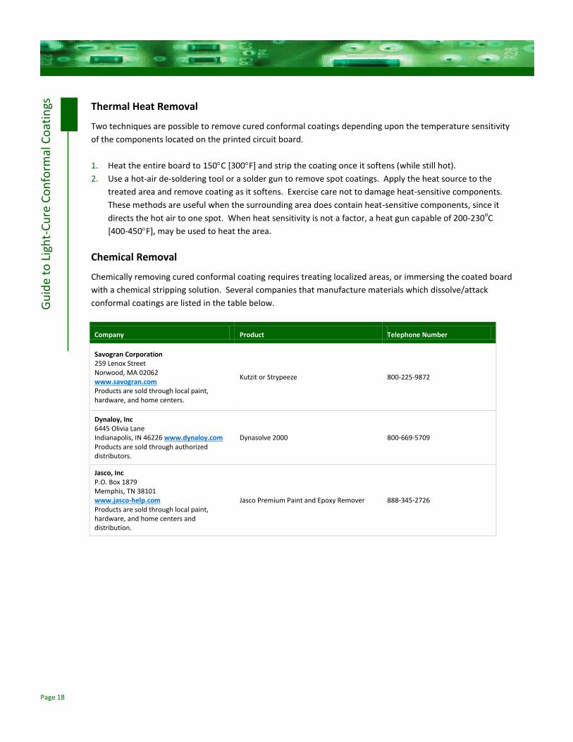
Chemical Removal
Chemically removing cured conformal coating requires treating localized areas, or immersing the coated board
with a chemical stripping solution. Several companies that manufacture materials which dissolve/attack
conformal coatings are listed in the table below.
Company Product Telephone Number
Savogran Corporation 259 Lenox Street Norwood, MA 02062 www.savogran.com Products are sold through local paint, hardware, and home centers.
Kutzit or Strypeeze 800-225-9872
Dynaloy, Inc 6445 Olivia Lane Indianapolis, IN 46226 www.dynaloy.com Products are sold through authorized distributors.
Dynasolve 2000 800-669-5709
Jasco, Inc P.O. Box 1879 Memphis, TN 38101 www.jasco-help.com Products are sold through local paint, hardware, and home centers and distribution.
Jasco Premium Paint and Epoxy Remover 888-345-2726

Page 19
Gu
ide
to L
igh
t-C
ure
Co
nfo
rmal
Co
atin
gs
FAQS
Question: Does liquid resin that flows under a component (into a shadowed area) cure over time?
Answer: It depends on the formulation and its secondary cure mechanism. UV/moisture-cure coatings will cure
over time without light exposure. Time alone does not cure UV/heat-cure conformal coatings.
Question: If a small amount of conformal coating material goes into a shadowed area and a secondary heat
cure is not used, what impact does the uncured conformal coating have on my board and components?
Answer: It depends on many variables including the amount of coating, board topography, and presence of
contaminants on the board. Small quantities of uncured conformal coating alone have not been known to
impact the long-term performance of boards. Dymax always recommends that measures be taken to eliminate
the presence of uncured conformal coating through controlled dispensing methods, and, when necessary,
multiple-cure mechanisms.
Question: Why does the conformal coating feel tacky or sticky on the surface minutes after curing?
Answer: The coating was likely not exposed to enough UV light. A high-intensity lamp utilizing a bulb with
maximum wavelength output at 365 nm (nanometers) is recommended. Dymax coatings should be tack free
almost immediately after cooling.
Question: How do you know if the conformal coating is cured?
Answer: When the coating is tack free and the coating in contact with the board is solidified. All light-cure
coatings feel tacky immediately after they are cured and still warm from the lamps. Tackiness should be judged
after the coating has cooled, which is often seconds after leaving the light source. Very soft coatings have a
slightly tacky feel, like soft rubber. To judge whether the coating flush to the board is cured, run a test specimen
and try to pick the coating away from the specimen using a sharp tool.
Question: How do you know if the material is cured in a shadowed area after a secondary cure?
Answer: For UV/Visible light-cure coatings, this work may include destructive and performance testing of parts
made with minimum and maximum amounts of coating, UV/Visible light intensity, and exposure time allowable
by the process.

© 2013 Dymax Corporation. All rights reserved. All trademarks in this guide, except where noted, are the property of, or used under license by Dymax Corporation, U.S.A.
The data contained in this bulletin is of a general nature and is based on laboratory test conditions. Dymax does not warrant the data contained in this bulletin. Any warranty applicable to the product, its application and use is strictly limited to that contained in Dymax’s standard Conditions of Sale. Dymax does not assume responsibility for test or performance results obtained by users. It is the user’s responsibility to determine the suitability for the product application and purposes and the suitability for use in the user’s intended manufacturing apparatus and methods. The user should adopt such precautions and use guidelines as may be reasonably advisable or necessary for the protection of property and persons. Nothing in this bulletin shall act as a representation that the product use or application will not infringe a patent owned by someone other than Dymax or act as a grant of license under any Dymax Corporation Patent. Dymax recommends that each user adequately test its proposed use and application before actual repetitive use, using the data contained in this bulletin as a general guide. GUI001 5/03/2013
Dymax Corporation 860.482.1010 [email protected] www.dymax.com
Dymax Oligomers &Coatings 860.626.7006 oligomers&[email protected] www.dymax-oc.com
Dymax Europe GmbH +49 (0) 611.962.7900 [email protected] www.dymax.de
Dymax UV Adhesives & Equipment (Shenzhen) Co Ltd +86.755.83485759 [email protected] www.dymax.com.cn
Dymax UV Adhesives & Equipment (Shanghai) Co Ltd +86.21.37285759 [email protected] www.dymax.com.cn
Dymax Asia (H.K.) Limited +852.2460.7038 [email protected] www.dymax.com.cn
Dymax Korea LLC 82.2.784.3434 [email protected] www.dymax.co.kr