Embed Size (px)
Citation preview

guide to
solutions
CONCRETEOVERLAY
JANUARY 2007

Introduction / 1
Overview of the Bonded Resurfacing Family / 2
Overview of the Unbonded Resurfacing Family / 3
Bonded Resurfacing Family
Bonded Concrete Resurfacing of Concrete Pavements / 4
Bonded Concrete Resurfacing of Asphalt Pavements / 6
Bonded Concrete Resurfacing of Composite Pavements / 8
Unbonded Resurfacing Family
Unbonded Concrete Resurfacing of Concrete Pavements / 10
Unbonded Concrete Resurfacing of Asphalt Pavements / 12
Unbonded Concrete Resurfacing of Composite Pavements / 14
Design of Concrete Overlays / 16
Useful Miscellaneous Design Details / 21
Concrete Overlay Materials / 24
Key Points for Concrete Overlay Construction / 26
Future Repairs / 28
Sources / 28
Contents
Produced byThis guide is a product of the National Center for Concrete Pavement Technology (CP Tech Center), Iowa State University.
Contributing AuthorsDale Harrington, P.E., Principal Senior Engineer, Snyder and AssociatesDan DeGraaf, P.E., Michigan Concrete Paving Association Randell Riley, P.E., Illinois Chapter ACPARobert Otto Rasmussen, P.E., Transtec Group
Jim Grove, P.E., PCC Paving Engineer, CP Tech CenterJim Mack, P.E., Cement Council of Texas
Editorial Staff
Mark Anderson-Wilk, Managing/Contributing EditorMarcia Brink, EditorOksana Opsomer, Copyeditor
Mina Shin, Graphic Designer and IllustratorBill Beach, Illustrator
CP Tech Center Concrete Overlays CommitteeAndy Bennett, P.E., Michigan Department of TransportationJim Cable, P.E., Iowa State UniversityDan DeGraaf, P.E., Michigan Concrete Paving AssociationJim Duit, Duit Construction Co., Inc., OklahomaTodd Hanson, P.E., Iowa Department of TransportationRandell Riley, P.E., Illinois Chapter ACPAMatt Ross, P.E., Missouri/Kansas Chapter ACPAJim Shea, New York State Chapter ACPAGordon Smith, P.E., Iowa Concrete Paving AssociationSam Tyson, P.E., Federal Highway AdministrationLeif Wathne, P.E., American Concrete Pavement AssociationMatt Zeller, P.E., Concrete Paving Association of Minnesota
CP Tech Center MissionThe mission of the CP Tech Center is to unite key transportation stake-holders around the central goal of advancing concrete pavement technology through research, tech transfer, and technology implementation.
DisclaimerThe opinions, recommendations, and conclusions expressed in this publication are those of the majority of the CP Tech Center Concrete Overlays Committee and contributors, and not necessarily those of the sponsors or other participating organizations.
AbbreviationsAASHTO American Association of State Highway and Transportation OfficialsACI American Concrete InstituteACPA American Concrete Pavement AssociationASR alkali-silica reactivity/reaction/reactiveASTM American Society for Testing and MaterialsC&G curb and gutterCRCP continuously reinforced concrete pavementsDBI dowel bar inserterDOT department of transportationFHWA Federal Highway AdministrationFRP fiber-reinforced polymerFWD falling weight deflectometerJPCP jointed plain concrete pavementsJRCP jointed reinforced concrete pavementsM-E mechanical-empiricalMRD material-related distressNCHRP National Cooperative Highway Research ProgramPCA Portland Cement AssociationPIARC World Road AssociationSCM supplementary cementitious materialTRB Transportation Research Boardw/cm water-to-cementitious materials
For More InformationFor technical assistance, contact your state paving association/ACPA chapter (find contact information with the My Locator tool at www.pavement.com).
For Additional Copies The American Concrete Pavement Association (ACPA) is stocking and distributing this guide. For additional copies, contact the association:
American Concrete Pavement Association 5420 Old Orchard Road, A100 Skokie, IL 60077 800-868-6733 (order processing) 847-966-6200 (fax)
Ask for ACPA publication TB021PAmerican ConcretePavement Association

�Guide to Concrete Overlay Solutions
Introduction
Bonded Resurfacing Family Unbonded Resurfacing Family
Bonded Concrete Resurfacing of Concrete Pavements–previously called bonded overlay–
Bonded Concrete Resurfacing of Asphalt Pavements–previously called ultra-thin whitetopping, UTW–
Bonded Concrete Resurfacing of Composite Pavements
Unbonded Concrete Resurfacing of Concrete Pavements–previously called unbonded overlay–
Unbonded Concrete Resurfacing of Asphalt Pavements–previously called conventional whitetopping–
Unbonded Concrete Resurfacing of Composite Pavements
Despite many successful projects, some public agencies and contractors have been hesitant to use concrete overlays. This lack of confidence has been based on a number of factors, including the misperception that concrete overlays are expensive or difficult to build.
This guide will help readers understand concrete overlays and develop confidence in their application. The guide provides the key elements of the six major types of concrete overlays along with specifics on materials, typical sections, and important construction elements.
Advantages of Concrete OverlaysConcrete overlays can serve as cost-effective maintenance and rehabilitation solutions for almost any combination of existing pavement type and condi-tion, desired service life, and anticipated traffic loading.
Across the country, most states have used at least one type of concrete over-lay to maintain or rehabilitate aging pavements. These overlays have been in service for decades in many locations. Experience has shown that well designed and constructed concrete overlays provide excellent performance, in many cases extending the life of existing pavements for an additional 30 years or more.
Reasons to consider a concrete overlay solution include the following:
1. Concrete overlays are not only a durable rehabilitation tool; they can also be a cost-effective maintenance tool. The wide range of overlay thicknesses that can be used, combined with the minimal preoverlay work required, results in the ability of concrete overlays to provide cost-effective solutions for a full spectrum of situations.
2. The existing pavement does not need to be removed for a concrete overlay to be placed. In most cases, concrete overlay projects have minimal removal and preoverlay repair costs. In addition, the existing pavement is utilized to provide additional structural and load-carry-ing capacity. The original investment in the existing pavement is thus extended with a new cost-effective concrete surface.
3. With normal concrete paving practices and careful attention to detail, concrete overlay projects can be completed as quickly and
efficiently as any other paving method. Concrete overlays are placed using single-pass construction (not multiple lifts). Nondestructive strength measurements allow many pavements to be opened to traffic within one day of overlay placement. Thin concrete overlays can also be opened quickly in hot weather.
4. Inch for inch, concrete overlays are one of the most cost-effective pavement alternatives. Maintenance and rehabilitation alternatives typically last longer than their asphalt counterparts with the same thickness.
5. Concrete overlays are recyclable. With today’s equipment, they can be removed economically and reused easily as high-quality and drainable base material for a future pavement.
Two Families of Concrete OverlaysThe terms used for concrete overlays in the past (ultrathin whitetopping, conventional whitetopping, bonded overlays, unbonded overlays, etc.) have tended to confuse people.
This guide replaces previously used terminology with more straightforward terms. All concrete overlay types fall into one of two families—the bonded resurfacing family and the unbonded resurfacing family. This guide uses the general term “concrete overlays” when collectively discussing both bonded and unbonded resurfacing solutions.
Bonded resurfacing projects require that the existing pavement be in good structural condition. The overlay eliminates surface distresses, and the exist-ing pavement continues to carry much of the load.
Unbonded resurfacing projects add structural capacity to the existing pave-ment. Constructed essentially as new pavements on a stable base, unbonded resurfacing projects do not require bonding between the resurfacing and the underlying pavement.
Both bonded resurfacing and unbonded resurfacing can be placed on existing concrete pavements, asphalt pavements, or composite pavements (original concrete pavements that have been resurfaced previously with asphalt).
In general, bonded resurfacing is used to eliminate surface distress when the existing pavement is in good structural condition.
Bonding is essential, so thorough surface preparation is necessary before resurfacing.
In general, unbonded resurfacing is highly reliable, with longer design life than rehabilitation with asphalt.
Minimal pre- resurfacing repairs are necessary for unbonded resurfacing.

� Guide to Concrete Overlay Solutions
Overview of the Bonded Resurfacing Family
Bonded Concrete Resurfacing of Concrete Pavements
Thickness: 2–5 in. (5.1–12.7 cm) depending on desired life (15–25+ years), anticipated traffic loading, and condition of underlying pavement
Bonded Concrete Resurfacing of Asphalt Pavements
Bonded Concrete Resurfacing of Composite Pavements
• Bond between existing pavement and overlay is essential to good performance as a monolithic pavement.
• If a project is to be expedited, all elements of the project, not just the pavement, need to be addressed.
• Typically used directly over concrete without additional repairs except for spot-repairing of severely deteriorated areas. Working cracks in existing pavement will reflect through.
• Concrete aggregate used should have thermal properties similar to those of existing pavement to minimize shear stress in bond.
• Existing joints must be in fair condition or be repaired.
• Be prepared for an accelerated sawing window. Match joints with those of the underlying pavement so the structure moves monolithically. Cut transverse joints full depth plus ½ in. (1.3 cm) and longitudinal joints at least T/2.
• Curing should be timely and adequate, especially near the edge, due to the surface-to-volume ratio and the risk of early-age cracks.
• Use when existing pave-ment is in good structural condition with some surface distress.
• Use to eliminate any surface defects; increase structural capacity; and improve surface friction, noise, and rideability.
• Can be used in locations where vertical clearances must be met, in mill and inlay sections, and in conjunction with widening.
Uses and Advantages Important Elements
Uses and Advantages Important Elements
Uses and Advantages Important Elements
• Use when existing pavement is in fair or better structural condition with surface distress.
• Use to eliminate surface distress such as severe rutting, shoving, and pothole problems; increase structural capacity; and improve surface friction, noise, reflectance, and rideability.
• Can be used in conjunction with widening.
• Bond between existing pavement and overlay is essential to good performance.
• If a project is to be expedited, all elements of the project, not just the pavement, need to be addressed.
• Thin milling may be required to eliminate significant surface distortions of 2 in. (5.1 cm) or more and provide good bond. Leave at least 3 in. (7.6 cm) remaining asphalt after milling.
• Control surface temperature of existing asphalt to below 120ºF (48.9ºC).
• Keep joints out of wheel paths, if possible.
• Curing should be timely and adequate.
• Bond is essential to good performance.
• If a project is to be expedited, all elements of the project, not just the pavement, need to be addressed.
• Examine profile for vertical distortion at joints that could signal a problem with the bottom layer.
• Thin milling of the existing pavement may be required to eliminate significant surface distortions of 2 in. (5.1 cm) or more and provide good bond. Leave at least 3 in. (7.6 cm) remaining asphalt after milling.
• Control surface temperature of existing asphalt to below 120ºF (48.9ºC).
• Small square panels reduce stresses. Keep joints out of wheel paths, if possible.
• Curing should be timely and adequate.
• Use when existing pave-ment is in fair or better structural condition with severe surface distress.
• Use to eliminate surface distress such as severe rutting, shoving, and pot-hole problems; increase structural capacity; and improve surface friction, noise, reflectance, and rideability.
• Can reduce underlying con-crete pavement temperature, minimizing expansion and buckling potential.
• Can be used in conjunction with widening.

�Guide to Concrete Overlay Solutions
Unbonded Concrete Resurfacing of Composite Pavements
Unbonded Concrete Resurfacing of Concrete Pavements
Unbonded Concrete Resurfacing of Asphalt Pavements
Overview of the Unbonded Resurfacing FamilyThickness: 4–11 in. (10.2–27.9 cm) depending on desired life (15–30+ years), anticipated traffic loading, and condition of underlying pavement.
• Full-depth repairs are required only where structural integrity is lost at isolated spots.
• Asphalt separator layer is important to isolate unbonded resurfacing from underlying pavement and minimize reflective cracking.
• Faulting (< ⅜ in. [9.5 mm]) is generally not a concern when the asphalt separation layer is 1 in. (2.5 cm) or more.
• With heavy truck traffic, adequate drainage design may be important to reduce pore pressure.
• Timing of joint sawing is important, particularly for thinner resurfacing. Shorter joint spacing helps minimize curling and warping stresses. No need to match joints with those of the underlying concrete pavement.
• Use when existing pavement is in poor condition, including with material-related distress such as D-cracking and ASR, and when underlying pavement and subbase are stable and uniform except for isolated areas that can be repaired.
• Use to restore structural capacity of the existing pavement and increase pavement life equivalent to full-depth pavement.
• Results in improved surface friction, noise, and rideability.
• Longer design life than rehabilitation with asphalt.
• Successfully used with high reliability.
• Can reduce underlying concrete pavement temperature, which helps reduce expansion and buckling.
• Can be used in conjunction with widening.
Uses and Advantages Important Elements
• Use when existing pavement is deteriorated (severe rutting, potholes, alligator cracking, shoving, and pumping) and when subbase is stable and uniform.
• Use to restore structural capacity of the existing pavement and increase pavement life equivalent to full-depth pavement.
• Eliminates rutting and shoving problems and results in improved surface friction, noise, and rideability.
• Longer design life than rehabilitation with asphalt.
• Successfully used with high reliability.
• Can be used in conjunction with widening.
• Full-depth repairs are required only where structural integrity is lost at isolated spots. Mill only severe surface distortions.
• Cracks in the asphalt will not reflect up since concrete overlay movement is independent of the underlying asphalt.
• Timing of joint sawing is important, particularly for thinner resurfacing.
Uses and Advantages Important Elements
Uses and Advantages Important Elements
• Full-depth repairs are required only where structural integrity is lost at isolated spots. Mill only severe surface distortions.
• Examine profile for distortion at joints.
• Existing asphalt serves as separator layer.
• Timing of joint sawing is important, particularly for thinner resurfacing.
• Use when existing pavement is deteriorated (severe rutting, potholes, alligator cracking, shoving, pumping, exhibiting past D-cracking and ASR) and when underlying pavement and subbase are stable and uniform except for isolated areas that can be repaired.
• Use to restore pavement’s structural capacity and increase pavement life equivalent to full-depth pavement.
• Eliminates rutting and shoving problems and improves surface friction, noise, and rideability.
• Longer design life than rehabilitation with asphalt.
• Successfully used with high reliability.
• Can reduce underlying concrete pavement temperature, which helps reduce expansion and buckling.
• Can be used in conjunction with widening.

Guide to Concrete Overlay Solutions �
Bonded Concrete Resurfacing of Concrete Pavements—previously called bonded overlay—
UsesConcrete pavements that are structurally sound but in need of increased structural capacity or improved rideability, skid resis-tance, and reflectivity characteristics can be enhanced with a 2–5 in. (5.1–12.7 cm) bonded concrete resurfacing.
The concrete resurfacing is bonded to the existing concrete pavement to form a monolithic section, thereby reducing stresses and deflections. Under certain conditions, a mill and inlay can be used if the existing pavement has significant surface issues but is structurally sound and the subbase is stable.
PerformanceBonded concrete resurfacing has been successfully used for over 90 years as a means of strengthen-ing old concrete pavement, providing a new smooth surface, repairing surfaces with popouts, or repairing other surface defects such as spalls, scaled areas, and areas with high steel near the surface.
The condition of the underlying concrete pave-ment has a significant effect on the performance of the resurfaced pavement.
A bonded concrete resurfacing increases the overall structural capacity of the pavement. This structural benefit only occurs, however, when the resurfacing and the underlying concrete behave monolithically. If bonding is not achieved, increased curling and loading stresses in the con-crete resurfacing can result, leading to an added
risk of early-age cracking. Thus, an effective bond is critical to the performance of this type of resurfacing project.
Factors that contribute to bonding are the strength and integrity of the existing concrete, the cleanliness of the surface, the consolida-tion of the overlay, and the jointing and curing techniques used.
Resurfacing Process
STEP �. PAVEMENT EVALUATION
An evaluation of the existing concrete pavement is necessary to ensure it is a good candidate for bonded resurfacing and, once resurfaced, it will be structurally sound enough to carry anticipated traffic loads. Information gathered through the evaluation is used to determine necessary spot repairs and to establish the concrete overlay design thickness.
The condition of the existing concrete pavement can be initially assessed through a visual examina-tion of the type, severity, and extent of existing distresses. Falling weight deflectometer (FWD) testing may be considered to aid in the analysis, depending on the design life and traffic volume. Additional information on concrete condition can be obtained through analysis of cores taken from the existing pavement.
The severity and extent of any deteriorated trans-verse cracking, pumping, and faulting should be considered in determining whether bonded con-crete resurfacing is appropriate. If deterioration is
not widespread, repairs should be made first and then the overlay constructed.
Where these distresses are widespread or too severe, however, bonded concrete resurfacing is probably not the best solution. If a concrete pavement with material-related distress such as alkali-silica reactivity (ASR) or D-cracking is resurfaced (assuming it is not cost effective to provide extensive repairs), the bonded resurfacing may have a shortened life.
STEP �. RESURfACING DESIGN
Resurfacing ThicknessThe design thickness for bonded concrete resurfacing is typically 2–5 in. (5.1–12.7 cm) depending on the desired load-carrying capac-ity and service life and the structural capacity provided by the underlying pavement.
The thickness can be determined using an estab-lished design procedure such as the AASHTO Guide for Design of Pavement Structures, 1993 edition (AASHTO Design Guide 1993). In the AASHTO procedure, bonded resurfacing thickness is equal to the difference between the structural capacity of a new full-depth pave-ment and the effective capacity of the existing pavement.
Mixture DesignConventional concrete mixtures have been suc-cessfully used for bonded concrete resurfacing. The concrete mixtures can be proportioned for rapid strength gain, minimum thermal expansion and contraction, and minimum shrinkage.
Figure 1. Bonded concrete resurfacing of good condition concrete pavement with surface distresses
Existing concrete pavement with surface distresses
Prepared surface
Monolithic pavement with new concrete surface

�Guide to Concrete Overlay Solutions
Some states use rapid-strength concrete mix-tures with a high cementitious material (cement and fly ash) content (not to exceed 660 lb/yd3 [299.4 kg/m3]), low water-to-cementitious mate-rial (w/cm) ratio, and smaller top-size aggregate (typically ¾ in. [1.9 cm]). These mixtures can be used with accelerating admixtures to provide the early strength required to place traffic on the bonded resurfacing within a short time period. A water-reducing admixture is used to reduce the w/cm ratio. Slump range is typically 2–3 in. (5.1–7.6 cm), which provides good bonding grout. For bonded resurfacing, it is better to have a wet, sticky mixture than a dry one. The use of high-modulus structural fibers can improve the toughness and post-cracking behavior of the con-crete and help control plastic shrinkage cracking.
A well-graded aggregate will reduce shrinkage and curling potential and thus reduce the risk of debonding. To help minimize the stress at the bond line, the resurfacing concrete should have thermal properties similar to those of the underlying concrete and use aggregates with as similar thermal characteristics as possible. Pore space in the aggregate should be fully saturated before batching; otherwise, the aggregate will tend to pull water from the mixture at early ages, increasing the possibility of shrinkage, which can lead to debonding. The maximum aggregate size of the resurfacing concrete should be one-third of the resurfacing thickness.
Joint DesignThe bonded resurfacing joint type, location, and width should match those of the existing pave-ment in order to create a monolithic structure. Matched joints eliminate reflective cracking and ensure that the two layers of the pavement structure move together, helping maintain bond-ing. Dowels or other load-transfer devices are not used in bonded concrete resurfacing.
Drainage DesignDuring evaluation and design of a bonded concrete resurfacing project, existing subgrade drainage should be evaluated, as would be done with asphalt resurfacing. If necessary, steps should be taken to ensure adequate drainage in the future.
STEP �. PRE-RESURfACING WORK
Pre-resurfacing RepairsPre-resurfacing repairs of certain distresses may be necessary to achieve the desired load-carrying capacity and long-term durability. The surface should be inspected for isolated pockets of dete-rioration that require repairs. See table 1.
For isolated areas that have wide random cracks, full-depth repairs may be necessary. When cracks (particularly working cracks) exist in the pave-ment to be resurfaced, reflective cracking will almost always occur. Crack cages over existing
cracks have been successfully used to prevent reflective cracking.
When voids are detected under existing slabs, the slabs should be stabilized through grout injection or other methods. Asphalt patches should be removed and replaced with concrete patches (or simply filled with concrete at the time of resurfac-ing) to ensure bonding of the concrete layers.
A consideration in performing repairs is whether movement in the underlying pavement will cause movement in the resurfacing. Any movement in the resurfacing that does not occur at matched joints could contribute to debonding and subse-quent deterioration of the resurfacing.
Surface PreparationSurface preparation of the existing concrete pavement is accomplished to produce a rough-ened surface that will promote bonding between the two layers. A variety of surface preparation procedures may be used, including shotblasting, milling, and sandblasting. A bonding grout or epoxy is not required. The most commonly used and most effective surface preparation procedure is shotblasting. Milling (used to lower the pave-ment elevation) has the potential drawback of causing surface microcracking and fracturing the exposed aggregate. If milling is used, the surface may require shotblasting or high water pressure blasting to remove microcracks.
Surface CleaningFollowing surface preparation, the concrete surface should be cleaned to ensure adequate bonding between the existing concrete surface and the new concrete resurfacing. Cleaning may be accomplished by sweeping the concrete surface, followed by cleaning in front of the paver with compressed air. Airblasting and water-blasting should be used only as supplementary cleaning procedures to remove loose material from the surface after shotblasting or sandblast-ing. Paving should commence soon after cleaning to minimize the chance of contamination.
Vehicles should be limited on the existing surface after it is prepared. If it is absolutely necessary to have vehicles on the existing concrete, care
Key Resources
ACI Committee 325 (2006), Trevino et al. (2004), and ACPA (1990a)
Table 1. Possible pre-resurfacing repairs for bonded resurfacing of concrete pavements
Existing pavement distress
Spot repairs to consider
Random cracks
Faulting
Pumping
Asphalt patch
Joint spalling
Scaling
Reflective cracking is likely if no repairs are made. Use crack cages or full-depth repairs for severe cracks.
Slab stabilization
Slab stabilization
Replace with concrete patch to ensure bonding.
Partial-depth repair
Remove with cleaning.
should be taken that they do not drip oil or other contaminants that could compromise the bond.
STEP �. CONSTRUCTION
Concrete PlacementGrade adjustments may be made to ensure the required thickness of the concrete. Conventional concrete paving practices and procedures are fol-lowed for bonded concrete resurfacing.
The best time to place bonded resurfacing is when the temperature differential between the existing slab and the new resurfacing is mini-mal. When possible, bonded resurfacing should be placed at the warmest part of the day, when expansion of existing concrete is near its maxi-mum and the movement is minimized once the resurfacing is placed.
CuringCuring is especially critical to bonded concrete resurfacing because the high surface area-to-vol-ume ratio makes the concrete more susceptible to rapid moisture loss. Within 30 minutes of placing the resurfacing, curing compound should be applied at twice the recommended rate. The finished product should appear as a uniformly painted solid white surface, with the vertical faces along the edges of the resurfacing also coated.
Joint SawingTimely joint sawing is necessary to prevent random cracking. Sawing should begin as soon as the concrete is strong enough that joints can be cut without significant raveling or chipping. Lightweight early-entry saws allow the sawing crew to get on the pavement as soon as possible. Transverse joints: The resurfacing’s transverse joints should match those of the underlying con-crete pavement. To help match joint locations, place guide nails on each edge of the existing pavement at the joints; after the resurfacing is placed, mark the joint with a chalk line connect-ing the guide nails. Saw to full depth plus ½ in. (1.3 cm). Longitudinal joints: Many believe that sawing longitudinal joints T/2 is sufficient, while others recommend sawing longitudinal joints full depth plus ½ in. (1.3 cm) to cut through the bond line.
Future RepairsThe recommended repair option for bonded concrete resurfacing is full-panel replacement. Concrete panels are easily removed and replaced. Another option is simply to mill and fill. If a panel is cracked or otherwise distressed but the ride quality of the pavement is not compromised, the panel may be left in place.

Guide to Concrete Overlay Solutions �
Bonded Concrete Resurfacing of Asphalt Pavements—previously called ultra-thin whitetopping, UTW—
Existing asphalt pavement with surface distresses
Milled and cleaned surface
New �–� in. (�.�–��.7 cm) bonded concrete resurfacing with square panels
UsesAsphalt roads, streets, and intersections that are in good-to-fair condition structurally but exhibit surface distresses such as rutting, shov-ing, slippage, and thermal cracking can be enhanced with a 2–5 in. (5.1–12.7 cm) bonded concrete resurfacing.
This type of concrete overlay is a bonded resurfacing that relies upon the existing asphalt pavement to carry some traffic loading.
PerformanceBonded concrete resurfacing has been suc-cessfully used in many states to maintain and rehabilitate asphalt pavements with surface defects. Numerous studies have shown bonded concrete resurfacing to provide a durable, reli-able surface course as long as there is sufficient bonding between the asphalt surface and the resurfacing and that the existing asphalt pave-ment is structurally adequate.
The condition of the underlying asphalt pavement and the uniformity of base sup-port have a significant effect on the resurfaced pavement performance.
Resurfacing Process
STEP �. PAVEMENT EVALUATION
An evaluation of the existing asphalt pavement is necessary to ensure it is structurally adequate to
Figure 2. Bonded concrete resurfacing of good-to-fair condition asphalt pavement with surface distresses
carry the anticipated traffic loads, to determine required milling depths, and to establish the bonded resurfacing design thickness. The struc-tural adequacy of the existing asphalt pavement can be assessed through a visual examination of the type, severity, and extent of existing distresses and through analysis of cores taken from the existing pavement. Falling weight deflectometer (FWD) testing may be considered to aid in the analysis, depending on the design life and traffic volume.
The evaluation results provide information on the stiffness of the asphalt pavement, subgrade sup-port conditions, and variations of these properties over the length of the project, thereby identifying localized areas of weakness requiring strengthen-ing. Asphalt pavements with significant structural deterioration, inadequate or uneven base/subbase support, poor drainage conditions, or stripping of asphalt layers are not good bonded resurfacing candidates; unbonded concrete resurfacing may be considered instead.
STEP �. RESURfACING DESIGN
Resurfacing ThicknessThe design thickness for bonded concrete resurfacing is typically 2–5 in. (5.1–12.7 cm), depending on the desired load-carrying capac-ity and service life and the structural capacity provided by the underlying pavement. Additional resurfacing thickness may be required in the transition section to prevent movement of the resurfacing panels adjacent to the existing asphalt
pavement and to reduce the potential for crack-ing due to traffic impact loadings.
Newly developed (2006) design procedures for bonded concrete resurfacing of asphalt pavements are available from ACPA. The ACPA spreadsheet incorporates the latest thinking in methods to address the limitations of the previous design procedures. The procedures are consistent with the proposed Mechanistic-Empirical Pavement Design Guide (NCHRP 2004, 2005, 2006) (ME-PDG) in that the user evaluates a proposed section against anticipated traffic to determine whether the section configuration, thermal characteristics, and joint geometry are adequate to meet the anticipated demands.
Mixture DesignConventional concrete mixtures have been suc-cessfully used for bonded concrete resurfacing. The concrete mixture can be proportioned for rapid strength gain, minimum thermal expansion and contraction, and minimum shrinkage.
Some states use rapid-strength concrete mixtures with a high cementitious material (cement and fly ash) content (though not to exceed 660 lb/yd3 [299.4 kg/m3]), low w/cm ratio, and smaller top size aggregate (typically ¾ in. [1.9 cm]). These mixtures can be used with accelerating admix-tures to provide the early strength required to place traffic on the bonded resurfacing within a short time. A water-reducing admixture is used to reduce the w/cm ratio. The slump range is typi-cally 2–3 in. (5.1–7.6 cm), which provides good

7Guide to Concrete Overlay Solutions
The amount of asphalt removal depends on the types and severity of distresses and the thick-ness of the asphalt pavement. The objective of removing material is not to obtain a perfect cross section. It is not necessary to completely remove ruts. A minimum of 3–4 in. (7.6–10.2 cm) of asphalt should be left after milling because of the reliance on the asphalt pavement to carry a portion of the load. Milling should leave at least half of the asphalt lift for optimum bonding since milling down to a point just above the tack line can lead to separation. The milled material may be used in constructing shoulders.
Further RepairsAfter milling, the surface should be inspected for isolated pockets of deterioration that require further repairs. For isolated areas that have a high number of wide transverse thermal cracks, a decision needs to be made whether to bridge the cracks with the bonded resurfacing or to clean and fill the cracks. Concrete can span normal asphalt longitudinal and transverse cracks. Filling cracks with emulsion, fly ash slurry, or sand is necessary only for cracks that have an opening greater than the maximum size aggregate used in the overlay.
Surface CleaningFollowing repairs, the asphalt surface needs to be cleaned to ensure adequate bonding between the existing asphalt surface and the new concrete resurfacing. Adequate bonding is very important to the performance of this resurfacing tech-nique. Cleaning may be accomplished by first sweeping the asphalt surface, then cleaning with compressed air. Pressure washing should only be considered when dust control is mandated or when mud has been tracked onto the milled surface. In no case should water or moisture be allowed to stand on the asphalt pavement prior to bonded resurfacing. In order to prevent contami-nation, it is important to avoid a large lag time between final surface cleaning and paving.
STEP �. CONSTRUCTION
Concrete PlacementWhen the surface temperature of the asphalt is at or above 120°F (48.9°C), surface watering can be used to reduce the temperature and minimize the chance of fast-set shrinkage cracking. No standing water should remain on the surface at the time the bonded resurfacing is placed. Water trapped in the milled surface can be blown off with compressed air.
Once the surface of the existing asphalt pavement has been prepared, paving is accomplished using either conventional fixed-form or slip-form con-
bonding grout. For bonded concrete resurfacing, it is better to have a wet, sticky mixture than a dry one. The use of high modulus structural fibers can improve the toughness and post-crack-ing behavior of the concrete and help control plastic shrinkage cracking.
Joint DesignThe recommended joint pattern for bonded resurfacing of asphalt is small square panels, typi-cally in the range of 3–8 ft (0.9–2.4 m), to reduce curling and warping stresses. It is recommended that the length and width of joint squares in feet be limited to 1–2 times the slab thickness in inches. In addition, if possible, longitudinal joints should be arranged so that they are not in the wheel path.
STEP �. PRE-RESURfACING WORK
Pre-resurfacing RepairsMost surface distresses can be removed through milling. Areas with potholes; localized, mod-erate-to-severe alligator cracking; or loss of base/subgrade support may require partial or full-depth spot repairs to achieve the desired load-carrying capacity and long-term durability. See table 2. All patching should be completed prior to milling.
MillingMilling may be used where surface distortions are 2 in. (5.1 cm) or greater. Milling should be minimized because it results in loss of structural support. The main objectives of milling prior to placing a functional overlay are (1) to remove significant surface distortions that contain soft asphaltic material, which would result in an inadequate bonding surface; (2) to roughen a portion of the surface to enhance bond develop-ment between the new concrete resurfacing and the existing asphalt; (3) to reduce high spots to help ensure minimum resurfacing depth and reduce the quantity of concrete needed to fill low spots; and (4) to match curb or adjacent structure elevations.
Key Resources
ACI Committee 325 (2006), Rasmussen and Rozycki (2004), and ACPA (1999a)
Table 2. Possible pre-resurfacing repairs for bonded resurfacing of asphalt pavements
Existing pavement distress
Spot repairsto consider
Fatigue cracking
Pothole
Deep rutting
Shoving, slippage
Thermal cracking
Full-depth repair patch
Full-depth repair patch
Milling
Milling
None
struction, the selection of which depends on the size of the project and any geometric constraints.
Because of the variation of the thickness of concrete, the concrete material is bid on a cubic-yard basis. Some states also include a bid item for placement on a square-yard basis.
CuringCuring is especially critical to bonded resurfacing projects because their high surface area–to-vol-ume ratio makes them more susceptible to rapid moisture loss. Curing is usually accomplished by applying a curing compound immediately after surface texturing (within 30 minutes of place-ment). In some states, the typical curing rate is increased by 1.5–2 times for bonded concrete resurfacing. The finished product should appear as a uniformly painted solid white surface, with the vertical faces along the edge of the bonded resurfacing also coated. Areas exhibiting a blotchy or spotty appearance should be recoated imme-diately. Be careful not to spill curing compound onto an area yet to be resurfaced, because it is a bond breaker.
Joint SawingTimely joint sawing is necessary to prevent random cracking. Joint sawing should commence as soon as the concrete has developed sufficient strength such that the joints can be cut without significant raveling or chipping. Lightweight early-entry saws (⅛ in. [3.2 mm] thick) may be used to allow the sawing crew to get on the pave-ment as soon as possible. Extra saws will likely be needed. Transverse joints can be sawed with con-ventional saws to a depth of T/4. Transverse joint saw-cut depths for early-entry sawing should not be less than 1¼ in. (3.2 cm). Longitudinal joints should be sawed to a depth of T/3. Joint sealing is not required.
Future RepairsBonded concrete resurfacing may be easily repaired using full-panel replacement. Another option is simply to mill and fill. Do not patch with asphalt, because the adjacent concrete panels will move and break the bond. If a panel is dis-tressed but the ride quality of the pavement is not compromised, the panel should be left in place. If a ride quality problem develops, the panel should be replaced before any pieces of concrete become loose from the resurfacing.

Guide to Concrete Overlay Solutions �
Bonded Concrete Resurfacing of Composite Pavements
Existing composite pavement with asphalt surface distresses
Milled and cleaned surface
New �–� in. (�.�–��.7 cm) thick bonded resurfacing with square panels
Figure 3. Bonded concrete resurfacing of good-to-fair condition composite pavement
UsesComposite (concrete on asphalt) pavements that are in good-to-fair condition structurally but exhibit surface distresses such as rutting, shoving, slippage, and thermal cracking can be enhanced with a 2–5 in. (5.1–12.7 cm) bonded concrete resurfacing.
This type of concrete overlay is a bonded resur-facing that relies upon the existing composite pavement to carry some traffic loading.
PerformanceBonded concrete resurfacing has been successfully used in many states to maintain and rehabilitate composite pavements with surface defects. The condition of the underlying composite pave-ment and the uniformity of base support have a significant effect on the performance of bonded concrete resurfacing.
Resurfacing Process
STEP �. PAVEMENT EVALUATION
An evaluation of the existing composite pave-ment is necessary to ensure it is structurally adequate to carry the anticipated traffic loads, to determine required milling depths, and to establish the bonded resurfacing design thickness. The structural adequacy of the existing compos-ite pavement can be assessed through a visual examination of the type, severity, and extent of existing distresses and through analysis of cores
taken from the existing pavement. Falling weight deflectometer (FWD) testing may be considered to aid in the analysis, depending on the design life and traffic volume.
The results can provide information on the stiff-ness of the asphalt pavement, subgrade support conditions, and variations of these properties over the length of the project, thereby identifying localized areas of weakness requiring strength-ening. Composite pavements with significant structural deterioration, inadequate or uneven base/subbase support, poor drainage conditions, or stripping of asphalt layers are not good candi-dates for a bonded resurfacing of less than 5 in. (12.7 cm).
Consideration should be given to any deteriora-tion of the asphalt surface course, as asphalt is a good reflector of structurally problematic areas such as subbase/subgrade problems, material-related distresses such as ASR and D-cracking, and other defects that result in vertical displacement of the profile and extensive fatigue cracking.
STEP �. RESURfACING DESIGN
Resurfacing ThicknessThe design thickness for bonded concrete resurfacing is typically 2–5 in. (5.1–12.7 cm) depending on the desired load-carrying capacity and service life and the structural capacity pro-vided by the underlying pavement.
Newly developed (2006) design procedures for bonded concrete resurfacing of composite pavements are available from ACPA. The ACPA spreadsheet incorporates the latest thinking in methods to address the limitations of the previous design procedures. The procedures are consistent with the proposed M-E PDG in that the user evaluates a proposed section against anticipated traffic to determine if the section configuration, materials’ thermal characteristics, and joint geometry are adequate to meet the demands.
Mixture DesignConventional concrete mixtures have been suc-cessfully used for bonded concrete resurfacing. The concrete mixture can be proportioned for rapid strength gain, minimum thermal expansion and contraction, and minimum shrinkage.
Some states use rapid-strength concrete mix-tures with a high cementitious material (cement and fly ash) content (though not to exceed 660 lb/yd3 [299.4 kg/m3]), low water-to-cementitious material ratio, and smaller top-size aggregate (typically ¾ in. [1.9 cm]). These mixtures can be used with accelerating admixtures to provide the early strength required to place traffic on the overlay within a short time. A water-reducing admixture is used to reduce the w/cm ratio. The slump range is typically 2–3 in. (5.1–7.6 cm), which provides good bonding grout. For bonded resurfacing, it is better to have a wet, sticky mixture than a dry one. The use of high-modulus structural fibers can improve the toughness and
�Guide to Concrete Overlay Solutions
Key Resources
ACI Committee 325 (2006), Rasmussen and Rozycki (2004), and ACPA (1999a)
MillingMilling may be used where surface distortions are 2 in. (5.1 cm) or greater. Milling should be minimized because it results in loss of structural support. The three main objectives of milling prior to a bonded resurfacing are (1) to remove significant surface distortions that contain soft asphaltic material, which would result in an inadequate bonding surface; (2) to roughen a portion of the surface to enhance bond develop-ment between the new concrete resurfacing and the existing asphalt; and (3) to reduce high spots to help ensure minimum resurfacing depth and reduce the quantity of concrete needed to fill low spots.
The amount of asphalt removal depends on the types and severity of distresses and the thick-ness of the asphalt pavement. The objective of removing material is not to obtain a perfect cross section. It is not necessary to completely remove ruts. A minimum of 3–4 in. (7.6–10.2 cm) of asphalt should be left after milling because of the reliance on the asphalt pavement to carry a significant portion of the load. Milling should leave at least half of the asphalt lift for optimum bonding since milling down to a point just above the tack line can lead to separation. The milled material may be used in constructing shoulders.
Further RepairsAfter milling, the surface should be inspected for isolated pockets of deterioration that require further repairs. For isolated areas that have a high number of wide transverse thermal cracks, a decision needs to be made whether to bridge the cracks with the bonded resurfacing or to clean and fill the cracks. Concrete can span normal asphalt longitudinal and transverse cracks. Filling cracks with emulsion, fly ash slurry, or sand is necessary only for cracks that have an opening greater than the maximum size aggregate used in the bonded resurfacing.
If there is vertical movement of the underlying concrete pavement immediately adjacent to a crack, the joint should be replaced, fibers added to mixture, or rebar used over the joint in com-posite pavements. Typically, 36 in. (91 cm) long bars are stapled to the existing pavement at 30 in. (76.2 cm) spacings, perpendicular to the crack.
Surface CleaningFollowing repairs, the asphalt surface needs to be cleaned to ensure adequate bonding between the existing asphalt surface and the new concrete overlay. Adequate bonding is very important to the performance of this resurfacing technique. Cleaning may be accomplished by first sweeping the asphalt surface, followed by cleaning with compressed air. Pressure washing should only be considered when dust control is mandated or when mud has been tracked onto the milled surface. No standing water should remain on the surface at the time the overlay is placed. In order to prevent contamination, it is important to avoid a large lag time between final surface cleaning and paving.
STEP �. CONSTRUCTION
Concrete PlacementWhen the surface temperature of the asphalt is at or above 120°F (48.9°C), surface watering can be used to reduce the temperature and minimize the chance of early-age shrinkage cracking. No standing water or moisture should remain on the surface at the time the bonded resurfacing is placed.
Once the surface of the existing asphalt pavement has been prepared, paving is accomplished using either conventional fixed-form or slip-form con-struction, the selection of which depends on the size of the project and any geometric constraints. Because of the variation of the concrete thickness, the concrete material is bid on a cubic-yard basis. Some states also include a bid item for placement on a square-yard basis.
CuringCuring is especially critical to bonded resurfacing projects because their high surface area-to-vol-ume ratio makes them more susceptible to rapid moisture loss. Curing is usually accomplished by applying a curing compound immediately after surface texturing (within 30 minutes of place-ment). In some states, the typical curing rate is increased by 1.5–2 times for bonded concrete resurfacing. The finished product should appear as a uniformly painted solid white surface, with the vertical faces along the edge of the bonded resurfacing also coated. Areas exhibiting a blotchy or spotty appearance should be recoated imme-diately. Be careful not to spill curing compound onto an area yet to be resurfaced, because it is a bond breaker.
Joint SawingTimely joint sawing is necessary to prevent random cracking. Joint sawing should commence as soon as the concrete has developed sufficient strength such that the joints can be cut without significant raveling or chipping, typically within 3–6 hours of concrete placement. Lightweight early-entry saws (⅛ in. [3.2 mm] wide blades) may be used to allow the sawing crew to get on the pavement as soon as possible. Extra saws will likely be needed. Transverse joints can be sawed with conventional saws to a depth of T/4. Transverse joint saw-cut depths for early-entry sawing should not be less than 1¼ in. (3.2 cm). Longitudinal joints should be sawed to a depth of T/3. Joint sealing is not required.
Future RepairsBonded concrete resurfacing may be easily repaired using full-panel replacement. Another option is simply to mill and fill. Do not patch with asphalt, because the adjacent concrete panels will move and break the bond. If a panel is dis-tressed but the ride quality of the pavement is not compromised, the panel should be left in place. If a ride quality problem develops, the panel should be replaced before any pieces of concrete become loose from the resurfacing.
post-cracking behavior of the concrete and help control plastic shrinkage cracking.
Joint DesignThe recommended joint pattern for bonded resurfacing of composite pavements is small square panels, typically in the range of 3–8 ft (0.9–2.4 m), to reduce curling and warping stresses. It is recommended that the length and width of joint squares in feet be limited to 1–1.5 times the slab thickness in inches. In addition, if possible, longitudinal joints should be arranged so that they are not in the wheel path.
STEP �. PRE-RESURfACING WORK
Pre-resurfacing RepairsMost surface distresses can be removed through milling. See table 3. Areas with potholes; local-ized, moderate-to-severe alligator cracking; or loss of base/subgrade support may require partial or full-depth spot repairs to achieve the desired load-carrying capacity and long-term durability.
Panel tenting (early stages of blowups) may be an indication that a void exists under existing panels. Sections with significant tenting can be repaired to relieve the pressure and provide uniform support before construction of a bonded resurfacing. All patching should be completed prior to milling.
Full-depth repair patch
Full-depth repair patch
Milling
Milling
None
Full-depth repair
Table 3. Possible pre-resurfacing repairs for bonded resurfacing of composite pavements
Existing pavement distress
Fatigue cracking
Pothole
Deep rutting
Shoving, slippage
Thermal cracking
Tenting (early stages of blowups)
Spot repairsto consider

Guide to Concrete Overlay Solutions �0
Unbonded Concrete Resurfacing of Concrete Pavements—previously called unbonded overlay—
UsesUnbonded concrete resurfacing is an excellent rehabilitation option for concrete pavements that exhibit some structural deterioration. An unbonded resurfacing of an existing concrete pavement can reestablish the strength lost through deterioration, provide a surface with desired rideability and other characteristics, and extend the performance life capable to carry exist-ing and future traffic loads.
This type of resurfacing is designed essentially as a new concrete pavement on a rigid base, assuming an unbonded condition between the layers. Unbonded resurfacing projects are typi-cally 4–11 in. (10.2–27.9 cm) thick, depending on the type and amount of traffic loads and the condition of the existing pavement. Unbonded resurfacing can be designed as jointed plain concrete pavements (JPCP) or continuously rein-forced concrete pavements (CRCP). A properly designed and functioning separator layer is criti-cal to the performance of this resurfacing type.
Unbonded resurfacing typically does not require extensive preoverlay repairs, though spot repairs of certain severely deteriorated areas may be necessary to minimize the risk of localized failure in the resurfacing.
PerformanceUnbonded resurfacing of concrete pavements has been successfully used in many states, with over 30 years of good to excellence performance. Critical factors that affect the performance of unbonded resurfacing include separator layer
design, resurfacing thickness, joint spacing lay-out, and load transfer design. In addition, weak subgrades can cause looseness and shifting of the fractured concrete, especially under saturated conditions, resulting in surface failure.
Resurfacing Process
STEP �. PAVEMENT EVALUATION
An evaluation of the existing concrete pavement is necessary to ensure it is a good candidate for an unbonded resurfacing; to identify what, if any, pre-resurfacing repairs are necessary; and to determine key inputs to the resurfacing design. A visual distress survey should be conducted and cores should be taken. On high truck volume roadways, falling weight deflectometer (FWD) testing should be considered to aid in the analysis.
The evaluation establishes whether the existing concrete and its subbase can provide a uniform strength platform and, if not, what actions are necessary to obtain that uniformity if an unbonded resurfacing is to be used. The evalu-ation also determines the existing pavement’s structural contribution as a stable base.
If there is evidence of numerous active panel movements, indicating potential nonuniform subgrade support or material-related distress, pavement analysis and corrective actions are necessary before the pavement is considered a candidate for unbonded resurfacing. The existing profile grade line should be carefully observed and areas of significant deviation investigated,
particularly at the joints. The reasons for the deviation and whether the movement has stopped need to be determined. Core analysis can provide information on material-related distress and expansive aggregates. If the movement is confined to an isolated area, a full-depth repair should be adequate. For faulted pavements, the cause can usually be attributed to the combination of some loss of load transfer between slabs and some loss of subgrade support. If the subbase is stable, the increase in the carrying capacity of the unbonded resurfacing has proven to be adequate to over-come faulting. Faulting is generally not a concern when a separator layer of 1 in. (2.5 cm) or greater is used. Edge drains have been successfully used to reduce the progression of faulting.
Panels tenting (early stages of blowups) may be an indication that a void exists under the slab. Sections with significant tenting can be repaired to relieve the pressure and provide uniform sup-port before unbonded resurfacing. Unbonded resurfacing of existing concrete pavement can substantially reduce the underlying pavement temperature during hot weather, thus helping to eliminate blowups.
STEP �. RESURfACING DESIGN
Unbonded resurfacing is designed similarly to new concrete pavements on a stable base, assum-ing a separated condition between the layers.
Separator Layer DesignThe separator layer design is one of the pri-mary factors influencing the performance of
Figure 4. Unbonded concrete resurfacing of poor condition concrete pavement
Existing concrete pavement
New unbonded resurfacing
Possible preoverlay repairs

��Guide to Concrete Overlay Solutions
unbonded resurfacing. It provides a shear plane that helps prevent cracks from reflecting up from the existing pavement into the new resurfac-ing. In addition, the separator layer prevents mechanical interlocking of the new pavement with the existing pavement, so both are free to move independently.
Typically, a fine-graded asphalt surface mixture has been used for the separator layer. On most pavements, a nominal 1 in. (2.5 cm) thick layer provides adequate coverage over irregularities in the existing pavement. The thickness could be slightly increased when irregularities are large enough to impact placement operations. The separator layer does not provide significant structural enhancement; therefore, the placement of an excessively thick layer should be avoided. Some states have modified the asphalt mixture because their surface mixes were not stable and were prone to scouring, particularly under heavy truck traffic. In an effort to reduce the scour pore pressure and increase stability, the sand content was reduced and the volume of ⅜ in. (9.5 mm) chip aggregate was increased. This modified mixture has a lower unit weight and lower asphalt content, and is comparable in cost with typical surface mixtures.
Resurfacing ThicknessUnbonded resurfacing thicknesses typically range from 6 to 11 in. (15.2 to 27.9 cm) when placed on primary roads and as thin as 4 in. (10.2 cm) on low-volume roads. The required resurfacing thickness is affected by the desired load-carrying capacity and service life, as well as the condition of the concrete base.
The thickness can be determined using an established design procedure for new concrete pavements. Additional research and development are needed to provide a design procedure that considers the effects of the separator layer.
Mixture DesignConventional highway mixtures are typically used for unbonded resurfacing of poor condi-tion concrete pavements. These mixtures can be used with accelerator admixtures to provide the early strength required to place traffic on the unbonded resurfacing within a short time period. Early opening can also be aided by use of maturity measurements.
Joint DesignLoad transfer is better in unbonded resurfacing than in new JPCPs because of the load transfer provided by the underlying pavement. Doweled joints are used for unbonded resurfacing of pavements that will experience significant truck traffic, typically pavements 8 in. (20.3 cm) and thicker.
Shorter joint spacing should be used to reduce the risk of early cracking due to curling stresses
that result from the stiff support provided by the underlying pavement (see table 4). Many states do not intentionally mismatch joints and have not experienced any adverse effects. However, some states still intentionally mismatch joints, according to previous guidance, to maximize the benefits of load transfer.
Drainage DesignProperly designed, constructed, and maintained edge drains help reduce pumping, faulting, and cracking. Without good drainage of the separation layer, pore pressure builds up from heavy truck traffic and can cause stripping of the asphalt separator.
Edge Support DesignIf shoulders are to be paved, tied shoulders may be preferable to widened resurfacing in unbonded resurfacing construction because of the increase in load transfer. Widened unbonded resurfacing slabs have increased risk of longitudinal cracking because of the high curling stresses resulting from stiff support conditions. Since some shoulder work is required for unbonded resurfacing, tied concrete shoulders can be included as part of the resurfacing project.
STEP �. PRE-RESURfACING WORK
Pre-resurfacing RepairsTypically, only the distresses that cause a major loss of structural integrity require repair. If significantly distressed areas are not shifting or moving and the subbase is stable, costly repairs typically are not needed, particularly with an adequately designed resurfacing. See table 5. As an alternative to numerous repairs, some state
Key Resources
ACI Committee 325 (2006), FHWA (2002b), and ACPA (1990b)
Table 5. Possible pre-resurfacing repairs for unbonded resurfacing of concrete pavements
Existing pavement condition
Possible repairs to consider
Faulting ¼–⅜ in. (6.4–9.5 mm)
Faulting > ⅜ in. (9.5 mm)
Significant tenting
Badly shattered slabs
Significant pumping
Severe joint spalling
CRCP with punchouts or other severe damage
None
Thicker separator layer
Full-depth repair
Full-depth repair
Full-depth spot repair and drainage improvementsClean
Full-depth repair
Table 4. Typical transverse joint spacing
Unbonded resurfacing thickness
Maximum transverse joint spacing
< 5 in. (12.7 cm)
5–7 in. (12.7–17.8 cm)
> 7 in. (17.8 cm)
6 x 6 ft (1.8 x 1.8 m) panels Spacing in feet = 2 times thickness in inches 15 ft (4.6 m)
DOTs increase the unbonded resurfacing thick-ness to provide additional strength.
Separator LayerUse of a sufficient separator layer can help ensure good performance of the unbonded resurfacing. Before separator layer placement, the existing pavement surface should be swept clean of any loose material either with a mechanical sweeper or an air blower. Conventional asphalt placement practices and procedures are followed for placing the separator layer.
STEP �. CONSTRUCTION
Concrete PlacementWhen the surface temperature of the asphalt sep-arator layer is at or above 120°F (48.9°C), surface watering can be used to reduce the temperature and minimize the chance of early-age shrinkage cracking. No standing water should remain on the surface at the time of resurfacing.
Conventional concrete paving procedures are fol-lowed for placing, spreading, consolidating, and finishing the unbonded resurfacing. Anchoring dowel baskets to the underlying concrete pave-ment is important. Alternatively, pavers equipped with dowel bar inserters can be used. Because of the variation of the concrete thickness, the concrete material is bid on a volume basis. Some states include a bid item for placement, measured on a square-yard basis.
CuringParticular attention should be paid to the envi-ronmental conditions during construction. Avoid excessively high temperature gradients through the pavement, which can cause slab curling and lead to poor performance. This “locked in” curling is of particular concern for unbonded resurfacing of concrete pavements because of the very stiff support conditions.
Joint SawingTimely joint sawing is necessary to prevent random cracking. Transverse joints can be sawed with conventional saws to a depth of between T/4 (min.) and T/3 (max.), but not less than 1¼ in. (3.2 cm). Transverse joint saw-cut depths for early-entry sawing should not be less than 1¼ in. (3.2 cm). Saw longitudinal joints to a depth of T/3.
Future RepairsThe recommended repair option for unbonded resurfacing is full-depth repair of distressed areas.

Guide to Concrete Overlay Solutions ��
Figure 5. Unbonded concrete resurfacing of poor-to-deteriorated condition asphalt pavement
UsesUnbonded concrete resurfacing is an excellent rehabilitation option for asphalt pavements that exhibit significant deterioration such as severe rutting, potholes, alligator cracking, shoving, and pumping. When properly designed and constructed, the unbonded resurfacing will increase the load-carrying capacity and extend the pavement life significantly.
This type of resurfacing is designed essentially as a new concrete pavement on a stable base course, assuming an unbonded condition between the layers. Unbonded concrete resurfacing projects are typically 4–11 in. (10.2–27.9 cm). Unbonded resurfacing can be designed as jointed plain concrete pavements (JPCP) or continuously reinforced concrete pavements (CRCP).
Unbonded concrete resurfacing typically does not require extensive preoverlay repairs, but spot repairs of certain severely deteriorated areas may be necessary to minimize the risk of localized failure in the resurfacing.
PerformanceUnbonded resurfacing of asphalt pavements has been successfully used in many states, with over 30 years of good to excellence performance in states such as California and Iowa. Uniform base support is an important factor affecting performance. Though this resurfacing type does not rely on bonding, some partial bond-ing between the resurfacing and existing asphalt
pavement can contribute to better performance of the pavement.
Resurfacing Process
STEP �. PAVEMENT EVALUATION
An evaluation of the existing asphalt pavement is necessary to ensure it is a good candidate for an unbonded resurfacing; to identify what, if any, pre-resurfacing repairs are necessary; and to determine key inputs to the resurfacing design. A visual distress survey should be conducted and cores should be taken. On high truck volume roadways, falling weight deflectometer (FWD) testing should be considered to aid in the analysis.
The evaluation establishes whether the existing asphalt and its subbase can provide a uniform platform for the unbonded resurfacing and, if not, what actions are necessary to obtain that uniformity if an unbonded resurfacing is to be used. In addition, the evaluation determines the existing pavement’s structural contribution as a stable base. The foundation support value should be determined to establish a thickness design that accounts for the contribution of the asphalt layer and its subbase.
STEP �. RESURfACING DESIGN
Unbonded resurfacing is designed similarly to new concrete pavements on a stable base, assum-ing an unbonded condition between the layers.
The asphalt serves as a stable base and contributes to the load-carrying capability of the unbonded resurfacing through increased bending stiffness of the resurfacing. The AASHTO Design Guide 1993 provides an approach to assessing the potential structural contribution of the existing asphalt to the unbonded resurfacing.
Resurfacing ThicknessUnbonded resurfacing thicknesses typically range from 6 to 11 in. (15.2 to 27.9 cm) when placed on primary roads and as thin as 4 in. (10.2 cm) on low-volume roads. The required resurfacing thickness is affected by the desired load-carrying capacity and service life, as well as the condition of the asphalt base.
The thickness can be determined using an established design procedures for new concrete pavements, such as the AASHTO Design Guide 1993 and the ACPA StreetPave program. In addition to these procedures, ACPA has devel-oped simple design charts to help determine the unbonded resurfacing thickness design. Using these charts, the overlay slab thickness is determined based on the number of trucks per day, the concrete’s flexural strength, and the base’s k-value.
Mixture DesignConventional highway mixtures are typically used in unbonded resurfacing of deteriorated asphalt. These mixtures can be used with accelerator admixtures to provide the early strength required
Existing deteriorated asphalt pavement
New unbonded resurfacing
Need for milling determined based on degree of surface
distortions
Unbonded Concrete Resurfacing of Asphalt Pavements—previously called conventional whitetopping—

��Guide to Concrete Overlay Solutions
Figure 6. Consider asphalt rut depth when determining saw-cut depth (ACPA 1998)
to place traffic on the resurfacing within a short time period. Early opening can also be aided by use of maturity measurements.
Joint DesignThe load transfer design is the same as for new concrete pavements. Doweled joints are used for unbonded resurfacing of pavements that will experience significant truck traffic, typically pave-ments 8 in. (20.3 cm) and thicker.
A maximum joint spacing in feet of 2 times the slab thickness (6 in. [15.2 cm] or greater) in inches is often recommended for unbonded resurfacing. A 6 in. (15.2 cm) resurfacing would thus receive 12 ft (3.7 m) joint spacing. The maximum recommended spacing is typically 15 ft (4.6 m). For pavements less than 6 in. (15.2 cm) thick, the maximum spacing in feet is 1.5 times the slab thickness in inches.
Drainage DesignProperly designed, constructed, and maintained edge drains help reduce pumping, faulting, and cracking. When an asphalt separator layer is used, adequate drainage may be important to minimize stripping due to pore pressure.
Designing Different SectionsPortions of a project with significantly different existing pavement and subbase conditions can be broken into separate sections and designed to specifically address those given conditions.
STEP �. PRE-RESURfACING WORK
Pre-resurfacing RepairsUnbonded resurfacing generally requires only minimal preoverlay repairs of the existing asphalt. If significantly distressed areas are not shifting or moving and the subbase is stable, costly repairs typically are not needed, particularly with an adequately designed resurfacing. See table 6.
Direct PlacementDirect placement without milling is recom-mended when rutting in the existing asphalt pavement does not exceed 2 in. (5.1 cm). Any ruts in the existing pavement are filled with concrete, resulting in a thicker resurfacing above the ruts.
MillingIf surface distortions in the existing pavement are 2 in. (5.1 cm) or greater, milling may be consid-ered. The two main objectives of milling prior to unbonded resurfacing are (1) to reduce high spots to help ensure minimum resurfacing depth and (2) to remove significant surface distortions that contain fractured asphalt material. Spot milling of only the parts of the project with significant distortion is often adequate. Over-milling is not recommended since it reduces the structural value of the pavement.
The amount of asphalt removal depends on the types and severity of distresses and the qual-ity of support. Usually 1–2 in. (2.5–5.1 cm) is removed. It is not necessary to completely remove ruts, but it is recommended that milling leaves less than 1 in. of distortions. No special effort is required to encourage bonding between the resurfacing and the underlying asphalt surface.
Surface CleaningBefore concrete placement, the asphalt surface should simply be swept. Remaining small par-ticles are not considered a problem.
STEP �. CONSTRUCTION
Concrete PlacementWhen the surface temperature of the asphalt is at or above 120°F (48.9°C), surface watering can help reduce the temperature and minimize the chance of fast-set, shrinkage cracking. No stand-ing water should remain on the surface at the time of resurfacing.
Conventional concrete paving practices and procedures are followed for placing, spread-ing, consolidating, finishing, and curing the unbonded resurfacing. Because of the variation of the thickness of concrete, the concrete material is bid on a volume (cubic-yard) basis. Some states also include a bid item for placement, measured on a square-yard basis.
Joint SawingTimely joint sawing is necessary to prevent random cracking. Transverse joints can be sawed with conventional saws to a depth of between T/4 (min.) and T/3 (max.). When there is evidence of some wheel rutting on the existing asphalt pavement, saw-cut depth is of particular concern for unbonded resurfacing because the distortions in the underlying asphalt pavement can effectively increase the slab thickness (see figure 6). Transverse joint saw-cut depths for early-entry sawing should not be less than 1¼ in. (3.2 cm). Longitudinal joints should be sawed to a depth of T/3.
Future RepairsThe recommended repair option for unbonded resurfacing is full-depth repair of distressed areas.Table 6. Possible pre-resurfacing repairs for
unbonded resurfacing of asphalt pavements
Existing pavement condition
Possible repairs to consider
Area of subgrade failure
Severe distress that results in variation in strength of asphalt
Potholes
Shoving
Rutting ≥ 2 in. (5.1 cm)
Rutting < 2 in. (5.1 cm)
Crack width ≥ 4 in. (10.2 cm)
Crack width < 4 in. (10.2 cm)
Remove and replace with stable material
Remove and replace with stable material
Fill with lean or plain concrete or asphalt
Mill
Mill
None or mill
Fill with lean concrete or flowable fill
None
Key Resources
ACI Committee 325 (2006), FHWA (2002a), and ACPA (1998)
Guide to Concrete Overlay Solutions ��
Unbonded Concrete Resurfacing of Composite Pavements
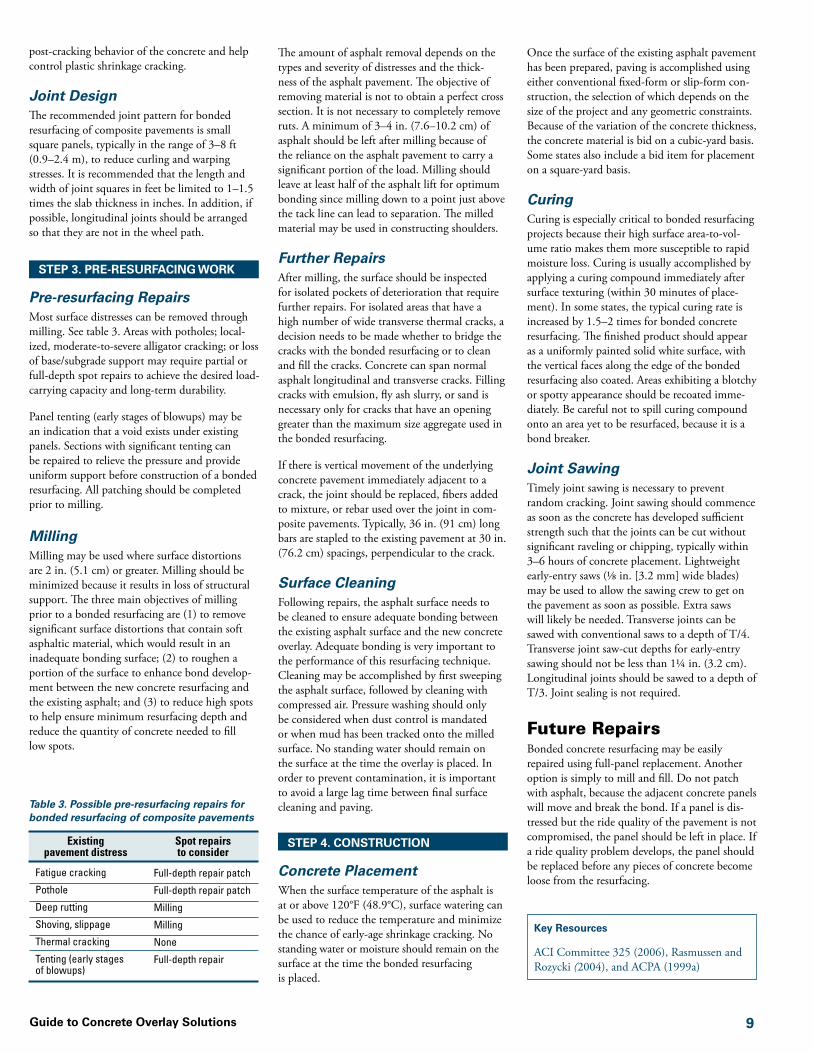
Figure 7. Unbonded concrete resurfacing of poor-to-deteriorated composite pavement
Existing deteriorated composite pavement
New unbonded resurfacing
Need for milling determined based on degree of surface
distortions
UsesUnbonded concrete resurfacing is an excellent rehabilitation option for composite (asphalt over concrete) pavements that exhibit significant dete-rioration such as severe rutting, potholes, alligator cracking, shoving, and pumping. When properly designed and constructed, unbonded resurfac-ing will increase the load-carrying capacity and extend the pavement life significantly.
This type of resurfacing is designed essentially as a new concrete pavement on a stable base course, assuming an unbonded condition between the layers. Unbonded concrete resurfacing projects are typically 4–11 in. (10.2–27.9 cm). Unbonded resurfacing can be designed as jointed plain concrete pavements (JPCP) or continuously reinforced concrete pavements (CRCP).
Unbonded concrete resurfacing typically does not require extensive preoverlay repairs, but spot repairs of certain severely deteriorated areas may be necessary to minimize the risk of localized failure in the resurfacing.
PerformanceUnbonded resurfacing has the potential to greatly extend the life of existing composite pavements. Uniform base support is an important factor affecting performance. Though this resurfacing type does not relay on bonding, some partial bonding between the resurfacing and existing
asphalt pavement can contribute to better perfor-mance of the pavement.
Resurfacing Process
STEP �. PAVEMENT EVALUATION
An evaluation of the existing pavement is necessary to ensure it is a good candidate for a unbonded resurfacing; to identify what, if any, pre-resurfacing repairs are necessary; and to determine key inputs to the resurfacing design. A visual distress survey should be conducted and cores should be taken. On high truck volume roadways, falling weight deflectometer (FWD) testing should be considered to aid in the analysis.
The evaluation establishes whether the existing pavement can provide a uniform platform for the unbonded resurfacing and, if not, what actions are necessary to obtain that uniformity if an unbonded resurfacing is to be used. In addition, the evaluation determines the existing pavement’s structural contribution as a stable base. The foundation support value should be determined to establish the thickness design that accounts for the contribution of the pavement to improving the bending stiffness of the concrete surface.
Consideration should be given to any deteriora-tion of the asphalt surface course, as asphalt is a good reflector of structurally problematic areas such as subbase/subgrade problems, material-
related distress such as ASR and D-cracking, and other defects that result in vertical displacement of the profile and extensive fatigue cracking.
A review of the existing profile grade line should be conducted and areas of significant deviation investigated through analysis of core samples in the laboratory. If there is evidence of numerous active panel movements, indicating potentially unstable or nonuniform subgrade support or material-related distress, detailed pavement analy-sis and corrective actions are necessary before the pavement is considered a good candidate for an unbonded resurfacing. If the movement is confined to isolated areas, a full-depth repair of the area should be considered.
Panel tenting (early stages of blowups) may be an indication that a void exists under existing panels. Sections with significant tenting can be repaired to relieve the pressure and provide uniform support before construction of an unbonded resurfacing.
Unbonded resurfacing and drains can sig-nificantly reduce the temperature and moisture and thus expansion of underlying pavements. Pavements that were subject to tenting and blow-ups typically do not experience this problem after an overlay is placed.
STEP �. RESURfACING DESIGN
Unbonded resurfacing is designed similarly to new concrete pavements on a stable base, assum-

��Guide to Concrete Overlay Solutions
ing an unbonded condition between the layers. The existing pavement serves as a stable base and contributes to the load-carrying capability of the unbonded resurfacing through increased bending stiffness of the resurfacing. The AASHTO Design Guide 1993 provides an approach to assessing the potential structural contribution of the existing pavement to the unbonded resurfacing.
Resurfacing ThicknessUnbonded resurfacing thicknesses typically range from 6 –11 in. (15.2–27.9 cm) when placed on primary roads and as thin as 4 in. (10.2 cm) on low-volume roads. The required resurfacing thickness is affected by the desired load-carrying capacity and service life, as well as the condition of the underlying pavement.
The thickness can be determined using an established design procedures for new concrete pavements, such as the AASHTO Design Guide 1993 and the ACPA StreetPave program. In addition to these procedures, ACPA has devel-oped simple design charts to help determine the unbonded resurfacing thickness design. Using these charts, the resurfacing slab thickness is determined based on the number of trucks per day, the concrete’s flexural strength, and the base’s k-value.
Mixture DesignConventional highway mixtures are typically used in unbonded resurfacing of deteriorated com-posite pavements. These mixtures can be used with accelerator admixtures to provide the early strength required to place traffic on the resurfac-ing within a short time period. Early opening can also be aided by use of maturity measurements.
Joint DesignThe load transfer design is the same as for new concrete pavements. Doweled joints are used for unbonded resurfacing of pavements that will experience significant truck traffic, typically pave-ments 8 in. (20.3 cm) and thicker.
A maximum joint spacing in feet of 2 times the slab thickness (6 in. [15.2 cm] or greater) in inches is often recommended for unbonded resurfacing. A 6 in. (15.2 cm) resurfacing would thus receive 12 ft (3.7 m) joint spacing. The maximum recommended spacing is typically 15 ft. (4.6 m). For pavements less than 6 in. (15.2 cm) thick, the maximum spacing in feet is 1.5 times the slab thickness in inches.
Drainage DesignProperly designed, constructed, and maintained edge drains help reduce pumping, faulting, and cracking.
Designing Different SectionsPortions of a project with significantly different existing pavement and subbase conditions may
be broken into separate sections and designed to specifically address those given conditions.
STEP �. PRE-RESURfACING WORK
Pre-resurfacing RepairsUnbonded resurfacing generally requires only minimal preoverlay repairs of the existing com-posite pavement. If significantly distressed areas are not shifting and the subbase is stable, costly repairs typically are not needed, particularly with an adequately designed resurfacing. See table 7.
Direct PlacementDirect placement without milling is recom-mended when rutting in the existing asphalt pavement does not exceed 2 in. (5.1 cm). Any ruts in the existing pavement are filled with concrete, resulting in a thicker resurfacing above the ruts.
MillingIf surface distortions in the existing pavement are 2 in. (5.1 cm) or greater, milling may be consid-ered. The two main objectives of milling prior to unbonded resurfacing are (1) to reduce high spots to help ensure minimum resurfacing depth and (2) to remove significant surface distortions that contain fractured asphalt material. Spot milling of only the parts of the project with significant distortion is often adequate. Over-milling is not recommended since it reduces the structural value of the pavement.
The amount of asphalt removal depends on the types and severity of distresses and the qual-ity of support. It is not necessary to completely remove ruts, but it is recommended that milling leaves less than 1 in. (2.5 cm) of distortions. No special effort is required to encourage bond-ing between the resurfacing and the underlying asphalt surface.
Table 7. Possible pre-resurfacing repairs for unbonded resurfacing of composite pavements
Existing pavement condition
Possible repairs to consider
Area of subgrade failure
Severe distress that results in variation in strength of asphalt
Potholes
Shoving
Rutting ≥ 2 in. (5.1 cm)
Rutting < 2 in. (5.1 cm)
Crack width ≥ 4 in. (10.2 cm)
Crack width < 4 in. (10.2 cm)
Remove and replace with stable material
Remove and replace with stable material
Fill with lean or plain concrete or asphalt
Mill
Mill
None or mill
Fill with lean concrete or flowable fill
None
Key Resources
ACI Committee 325 (2006), FHWA (2002a), and ACPA (1998)
When milling composite pavements, the condi-tion of the remaining asphalt surface should be examined for large fractured or separated layers. If the remaining old asphalt is too brittle or broken up to provide adequate separation, a new separator layer should be constructed. Without an adequate separation layer, working cracks from the underlying concrete could cause reflective cracking of the unbonded resurfacing.
Surface CleaningBefore concrete placement, the asphalt surface should simply be swept. Remaining small par-ticles are not considered a problem.
STEP �. CONSTRUCTION
Concrete PlacementWhen the surface temperature of the asphalt is at or above 120°F (48.9°C), surface watering can help reduce the temperature and minimize the chance of early-age shrinkage cracking. No stand-ing water should remain on the surface at the time of resurfacing.
Conventional concrete paving practices and procedures are followed for placing, spreading, consolidating, finishing, and curing the concrete overlay. Because of the variation of the thick-ness of concrete, the concrete material is bid on a volume (cubic-yard) basis. Some states also include a bid item for placement, measured on a square-yard basis.
Joint SawingTimely joint sawing is necessary to prevent random cracking. Transverse joints can be sawed with conventional saws to a depth of between T/4 (min.) and T/3 (max.). When there is evidence of some wheel rutting on the existing asphalt pavement, saw-cut depth is of particular concern for unbonded resurfacing because the distortions in the underlying asphalt pavement can effectively increase the slab thickness (see figure 6). Transverse joint saw-cut depths for early-entry sawing should not be less than 1¼ in. (3.2 cm). Longitudinal joints should be sawed to a depth of T/3.
Future RepairsThe recommended repair option for unbonded resurfacing is full-depth repair of distressed areas.

Guide to Concrete Overlay Solutions ��
Design of Concrete OverlaysThe purpose of this booklet is not to give the engineer all details needed to design a concrete overlay section. This section provides a basic explanation of the underlying design concepts and an outline of the strategy and resources necessary to implement concrete overlay projects as part of an overall pavement maintenance and rehabilitation program.
Given today’s limited highway funding, pavement engineers may be required to perform resurfacing designs more often than designs for new pave-ments. With an aged and highly varied highway network, clear and reliable guidance is needed for the design of high-quality concrete overlays.
Guidance for concrete overlay design has been published by ACI, AASHTO, FHWA, PIARC, NCHRP, ACPA, PCA, the U.S. Army Corps of Engineers, Federal Aviation Administration, and various state departments of transportation. These procedures use a variety of underlying assumptions and design strategies. It is important for the designer to understand the interaction of the design with both the materials that are selected and the process of construction.
Concrete overlay projects can be competitive in initial cost when expected service life is similar to that of an asphalt pavement.
Bonded ResurfacingBonded concrete resurfacing is a strategy intended primarily to improve the surface condi-tion of the existing pavement and extend the life of the existing underlying platform. Though some structural improvement results from the resurfacing, that is usually not the primary objective. Functional performance, including tire–pavement noise and friction or skid resis-tance, can also be improved through the use of bonded resurfacing.
Unbonded ResurfacingUnbonded concrete resurfacing is usually designed to provide a service life more typically associated with new pavements. A key advantage to constructing an unbonded resurfacing versus reconstruction is the elimination of a significant amount of excavation work; thus, a greater per-cent of the available funds are spent directly on the roadway surface.
Unbonded resurfacing not only provides struc-tural enhancement, it has the added bonus of eliminating existing surface distresses. Unbonded resurfacing is typically designed with the intent of being able to tolerate excess joint degradation, existing cracking, and localized failures in the
underlying pavement structure. Proper character-ization of the underlying structure will result in the best balance between cost and performance.
Design InputsRegardless of the procedure used, the process of design begins with recognition of a number of common inputs to the design process. These include defining the scope of the intended project and its intended structural performance requirements. Deciding whether the overlay is to last 15 years or 30 years will affect the extent of repairs to the existing pavement and the design inputs. These in turn influence the thickness, the amount of repair, and thus the cost of the overlay. See figure 8. The engineer is also required to char-acterize and understand the existing pavement structure, the anticipated traffic loading, and the materials expected to be used. In some cases, climatic influences may play a role, particularly with bonded concrete resurfacing.
Existing Pavement CharacterizationThe design and performance of a concrete overlay is affected by the condition of the exist-ing pavement structure. Bonded and unbonded resurfacing both benefit from the load-transfer capabilities of the existing pavement. Bonded resurfacing projects are influenced to a greater degree by the underlying pavement condition. Effective characterization is therefore important in selecting the proper type of concrete overlay to build and whether it should be in the bonded or unbonded family.
Surface Considerations
Because of the thinness of bonded resurfac-ing, these projects tend to be more sensitive than the thicker unbonded resurfacing proj-ects to the factors considered in the preoverlay pavement evaluation.
The first step in designing a bonded resurfac-ing project is a thorough characterization of the existing pavement. At the very least, the existing pavement section should be verified with cores or historical records. The existing pave-ment structure should also be evaluated for its overall condition.
At least 2–3 in. (5.1–7.6 cm) of existing asphalt pavement structure should remain for bonded resurfacing to be considered practical. If the existing surface is milled, the engineer should immediately inspect the condition of the remain-ing pavement. Areas showing distress should be repaired and the thickness of the resurfacing increased in these locations.
If the pavement is found to be in poor condition with many localized failures, it is an indication of significant base failures. Bonded resurfacing may not be advisable. Condition evaluation permits the pavement engineer to determine the quantity and location of preoverlay repair required. Depending upon the forecast costs of these repairs, the engineer may determine that it is more cost-effective to select an unbonded resurfacing solution that is less sensitive to the underlying pavement condition.
Structural Considerations
For unbonded resurfacing of concrete pavements, some agencies note the underlying pavement joint locations and intentionally place the joints in the new resurfacing away from those joints such that they are mismatched. The rationale for this is that load transfer will be improved. Other agencies discount this idea in favor of a more contractor-friendly approach. In this case, joints are simply placed where they would normally be according to the type of design being built. Both strategies have resulted in good performance.
For bonded and unbonded resurfacing of existing asphalt or composite pavements, the layer moduli should be determined through nondestructive falling weight deflectometer (FWD) testing. Cores are recommended for overlay projects that involve an existing asphalt surface. If possible, a measure of the efficiency of the joints and other discontinuities to load transfer should also be measured using an FWD.
When overlaying composite pavements, it should be noted that the asphalt layer is a good reflector of the existing base support. If the joints and other discontinuities of the underlying concrete are visible and extremely distressed or exhibiting evidence of severe faulting, these should be char-acterized. Excessive or visibly large deflections under truck loading may require attention prior to resurfacing.
Figure 8. Design factors that affect one another

�7Guide to Concrete Overlay Solutions
It should be noted that random cracks do not necessarily lead to faulting and reduction in ser-vice condition. Many miles of concrete overlays have been built that have performed very well with no regard or consideration for cracking in the underlying platform.
Given this basic information about the exist-ing system and then accounting for the possible costs of preoverlay repair, the engineer can begin to move into the determination of the required thickness of the overlay.
Traffic CharacterizationTo develop a proper pavement design, the antici-pated future traffic loading should be known as accurately as reasonably possible. Care must be taken not only to measure or predict current traffic characteristics, but also to assign reasonable growth characteristics.
A prediction of the number of trucks should be made over the design life. Measures sometimes include a prediction of the number of equiva-lent single-axle loads based on the anticipated traffic distribution. This approach is taken in the AASHTO Design Guide 1993 and is used by many state DOTs. In this case, the designer should not approach traffic estimates with conser-vative estimates. It is better to make a reasonable estimate and adjust for uncertainty later.
Alternative mechanistic-empirical pavement design procedures use a distribution of traf-fic loading. This loading describes the number, weight, and geometries of the associated axle loads. Sometimes this is further distributed by the time of day and even the season. Highly sophisti-cated models include the distribution by lane and the wander of the wheel within the lane.
The difficulty of obtaining information to this level of detail is sometimes significant. Additional traffic characterization information quickly crosses a point of diminishing returns where it no longer has significant impact on the design thickness. A number of typical distributions available in the M-E PDG may be adequate for most situations.
Material PropertiesCertain properties of the overlay concrete should be known or estimated prior to the design process. This provides the designer additional flexibility to adjust the designs to available material options that can be used to reduce costs without compromising performance.
Regardless of the design procedure used, the designer should also define the degree of support directly beneath the structural layers. In terms of what is defined as a “structural layer” (as opposed to part of the support system), departure from
the AASHTO procedure is becoming increas-ingly common, particularly in resurfacing. For example, using the conventional AASHTO design method for new concrete pavements, an asphalt layer is considered a support layer. The property defining this support, the modulus of subgrade reaction, or k-value, describes the response of the material immediately beneath the concrete pavement. When using the design procedures, it is important to understand at what location in the pavement structure the k-value is being considered. In other approaches to design, the flexural capacity of the asphalt layer is consid-ered as a structural component with the specific contribution depending on the degree of bond with the concrete. In this case, the k-value would describe the materials beneath the asphalt.
Strength of the concrete is one of the key design inputs, but this too is often misunderstood. The designer should use a strength that is consistent with the assumptions of the design method being used. For example, the AASHTO methods require third-point flexural strength in 28 days, yet it is not uncommon for designers to errone-ously use the strength found in the construction specifications. Since this value is often lower, it can result in an unnecessarily thick overlay that drives up cost.
Some methods require an estimate of the modu-lus of elasticity of the materials. This is often of secondary importance in unbonded overlays and has negligible impact in terms of thickness. However, this property becomes more important in bonded resurfacing projects.
In some mechanistic-based procedures, the coef-ficient of thermal expansion of the concrete is also used. Though the effect of this property is increasingly being considered in thicker overlays and even new pavements, it can have a much more significant effect on the thickness of bonded resurfacing designs.
Climatic FactorsOverlay performance depends on climatic factors, both those during construction and in the long term. Relatively thin bonded resurfacing sections are more susceptible to adverse weather condi-tions that may affect the ability of the concrete to retain moisture, prevent excessive heat buildup, or prevent freezing. Materials should be selected that are compatible with the anticipated climate and freeze/thaw conditions. Joints and load transfer systems should be designed to accommo-date the movements of the joints due to seasonal changes in pavement temperature.
Curling and warping are also considerations for pavement designers. Controlling large variations in temperature and relative humidity during con-struction can help improve overlay performance.
ConstraintsPotential constraints such as surface drainage should be considered in the design.
Curb and gutter (C&G) sections may pose issues with respect to how to design a concrete overlay. Projects might include removal and replacement of the existing C&G, construction of an inlay with the final pavement elevation matching the existing C&G, or even an encasement of the existing C&G with a new system. Barriers and ditches can lead to similar design challenges.
Overhead clearance is also another potential issue. Depending on the location of the design, various regulations for minimum overhead clear-ance may apply. The final pavement elevation and thickness may need to be limited or measures taken to raise overhead obstacles. Alternatively, it may be preferred to conduct full-depth recon-struction or build an alternative section at such locations.
Adding new lanes or shoulders can also pres-ent issues unique to concrete pavement design, especially if there is a change in the underlying support of the overlay, or if the overlay is to join a full-depth concrete pavement. Joint load transfer systems are frequently used in these cases. Tiebars are used to help provide aggregate interlock. Additional measures should be taken in the design to minimize differential settlement or water infiltration at these locations. For the same reasons, intersections and block-outs for utilities need to be understood, and joint patterns devel-oped that will minimize uncontrolled cracking.
Another important constraint is risk. Designers are sometimes charged with making decisions based on limited amounts of information. This is particularly true in rehabilitation project designs. Decisions on the design selection should be logical and defendable. The designer should be aware of the impact that selecting the reliability level can have on the final design thickness. In AASHTO design procedures, the reliability level and the overall standard deviation result in an increase in the design traffic used in determin-ing the thickness. Appropriate selection of these parameters can build in a predictable level of risk.
Distress ModeAn understanding of the modes of distress as defined by the design procedures is also important. Pavement engineering is currently undergoing rapid changes in this area. Existing AASHTO Design Guide 1993 methods are based on a “serviceability” model. This model predicts an index or designs for an index under a stated set of conditions. The index describes a general overall condition that encompasses many factors associated with pavement deterioration. These

Guide to Concrete Overlay Solutions ��
typically include faulting, cracking, patching, and pavement roughness.
Advancements in computing hardware and the desire to better understand what is occurring as pavements fail has led to newer AASHTO and industry-developed methods that, in essence, break apart the serviceability model into its individual components. Pavement designs are evaluated for “multimodal” deteriora-tion techniques that consider one or more of the parameters.
Multimodal failure techniques carry a number of advantages. They may aid in forecasting potential maintenance and they may assist in developing more effective and cost-efficient designs.
Design SelectionIn most cases, the designer will have an idea of the likely feasible alternatives based on the prede-sign survey of the project. However, in selecting the final design, it is important for the engineer to anticipate the condition of the existing section
at the time of actual construction of the new concrete surface. In many cases, construction will not begin for at least two or three years. Some degradation of the existing structure should be anticipated and considered in the analysis. Allowing for this continued degradation in the surface condition, the designer can begin the process of considerating feasible design alterna-tives. See table 8.
Design of Bonded ResurfacingBonded resurfacing projects depend upon the integrity of the underlying layer and the bond to it in order to assist in horizontal shear transfer at the bond plane. This horizontal shear transfers stresses into the underlying lay-ers, thereby decreasing tensile stresses in the bonded resurfacing.
Bonded Resurfacing of Concrete Pavements
Historically, the design of bonded resurfacing of concrete pavements has used a “design defi-ciency” or “remaining life” approach. The mode
of failure most commonly used is serviceability. This is largely due to the fact that most pave-ment engineers today are comfortable with the concept. The existing pavements in these cases have not failed. However, it is assumed that some of the pavement life has been consumed in either fatigue or serviceability, depending upon the design procedure being used.
First, standard design methods are used to deter-mine the required thickness of a new pavement based on the anticipated traffic, planned materials to be used, and other parameters typically consid-ered in new pavement design.
Having determined the overall required pavement thickness, the pavement thickness of the existing section is calculated. This thickness corresponds to the thickness required to carry the number of loadings to failure. In AASHTO Design Guide 1993 and earlier terminology, this is simply the change in serviceability and corresponds to the “remaining life.” Additional minor adjustments may also be made having to do with observations of existing pavement condition, but these are
Table 8. Summary of design considerations for the different types of concrete overlay solutions
Type Current Design Failure Mode
Currently Recommended Design Method
Areas for Model Enhancement
Includes Fiber Models
Joint Spacing is a Design
Consideration
k-value Location
Bonded Resurfacing Family
Bonded resurfacing of concrete pavements
Serviceability AASHTO Design Guide 1993, 1998, or 2002
Description of stresses at bond plane
N N Top of subbase
Bonded resurfacing of asphalt pavements
Mechanistically based multimodal; corner crack bond plane failure and asphalt fatigue
ACPA 2006 Bond plane vertical stress and asphalt condition
Y Y Bottom of asphalt layers
Bonded resurfacing of composite pavements
Serviceability or mechanistically based multimodal
AASHTO Design Guide 1993, 1998, or 2002
Modified ACPA 2006
Interaction of separator layer with resurfacing and bond
AASHTO Design Guide 1993, 1998, or 2002: N
Modified ACPA: Y
AASHTO Design Guide 1993: N
AASHTO Design Guides 1998 and 2002: Y
Modified ACPA: Y
AASHTO Design Guide 1993, 1998, and 2002: top of existing pavement
Modified ACPA: top of subgrade and subbase layers
Unbonded Resurfacing Family
Unbonded resurfacing of concrete pavements
Serviceability AASHTO Design Guide 1993, 1998, or 2002
Bond plane N N Top of subbase
Unbonded resurfacing of asphalt pavements
Serviceability AASHTO Design Guide 1993, 1998, or 2002
Minor influence of bond
N N Top of asphalt layer
Unbonded resurfacing of composite pavements
Serviceability AASHTO Design Guide 1993, 1998, or 2002
Joint spacing related to stiffness of platform and minor influence of bond
N N Top of asphalt layer

��Guide to Concrete Overlay Solutions
somewhat subjective. After the adjustments, the resulting number represents how much effective pavement thickness is actually available to be further “consumed” or used in the new pavement system in addition to the new resurfacing.
The difference in the thickness calculated for a new pavement and this effective section is the “design deficiency” or the required thickness of the new section that should be bonded to the existing pavement. For further informa-tion see the AASHTO Design Guide 1993 (pp. III-136–145).
Critical to the performance of this type of resurfacing is the development of bond strength between the two layers. Existing design proce-dures for bonded resurfacing do not specifically address this issue, treating it primarily as a construction issue. If the section is built correctly and proper curing procedures are used, bond strength is usually not a problem. However, extreme daytime to nighttime temperature swings can sometimes trigger premature delamination failures. If temperature differentials in excess of 20˚F (6.7˚C) are anticipated, the section should be protected or paving at night should be considered.
Joints in designs of this type are matched to the existing section and cut full depth plus a ½ in. (1.3 cm) of the resurfacing for transverse and at least T/2 for longitudinal joints. Designs for resurfacing of existing CRCPs are also possible. In the case of CRCPs, however, there is no need to match the transverse joints since none exist with the exception of terminal joints or lugs.
The use of steel reinforcement or dowels is not usually a consideration for designs of this type, except when the resurfacing is unusually thick, new shoulders are being tied, or there is also a desire to retrofit load transfer.
Properly built, bonded resurfacing can reasonably be expected to provide a minimum service life of 15 years before maintenance is required. The first clue of problems on these resurfacing projects is usually delamination at the bond plane, quickly followed by classic fatigue failure at isolated joint locations. These can be repaired using partial-depth repair techniques if the underlying slab remains sound.
Bonded Resurfacing of Asphalt Pavements
A unique feature of bonded resurfacing of asphalt pavements (previously called ultrathin whitetop-ping) is the consideration of joint spacing and its influence on the development of temperature-induced curling and warping stresses.
The original design procedures for this resurfac-ing type were published by American Concrete Pavement Association in 1998 following 10 years of research and development in locations across
the United States. A new, statistically fitted model of the mechanistically derived and calibrated results was produced. It predicted the maximum stress likely for the principal mode of failure. The principal mode of failure and the first sign of problems have been corner breaks of the panels.
In 2004, ACPA refined its fatigue models to incorporate newer probabilistic methods into its pavement design procedures. During develop-ment and revision of the procedures, it was recognized that for this particular type of resur-facing, the precursor to panel breakup was usually delamination stemming from failure in either the bond plane or the underlying asphalt layer.
Revisions completed in late 2005 and released for general use in early 2006 applied probabilistic techniques to both of these modes of failure. The new procedures reflect a multimodal “weak-est link” approach to design. In this approach, the design parameters are input into the design model; and the stresses in the corner model for the concrete, the strains in the bottom of the asphalt layer, and the horizontal stresses in the bond plane are evaluated. These stresses and strains are compared against ACPA’s new fatigue model for concrete, existing Asphalt Institute design fatigue models for asphalt layers, and a horizontal shear data model based on data obtained from Iowa, Florida, and Colorado stud-ies of concrete bonded to asphalt. Each mode of failure is evaluated using probabilistic techniques.
In addition to the probabilistic adaptation of the mechanistic procedures, new advancements in materials were included, particularly with regard to the inclusion of fibers. The effect of fibers in the models is based on their ability to enhance the fatigue resistance of the concrete. The design procedure for fibers is open ended in that as new fibers are developed and properties are estab-lished, these can be incorporated accordingly.
Probably one of the more confusing aspects in the design of bonded resurfacing of asphalt is the consideration of the supporting platform. For designs of this type, the classic modulus of sub-grade reaction or k-value described earlier is based on the value at the bottom of the asphalt layer rather than at the bottom of the concrete layer.
Bonded resurfacing joint design is a distinguish-ing characteristic when these projects are placed in the field. The transverse and longitudinal joint spacings are always under 6 ft (1.8 m) in length as determined by the design analysis. It is impor-tant that joints in this type of resurfacing be cut as quickly as possible to minimize the likelihood of curling stresses developing, triggering delami-nation at the edge of the pavement. Early-entry saws are usually used.
Since existing sections of bonded resurfacing of asphalt are fairly young, actual service life has yet to be determined, but based on 18 years of per-
formance data, it appears quite likely that 15–25 years of service can be expected from this type of resurfacing, provided it is constructed properly. This technology continues to evolve and is one of the most dynamic areas of interest in concrete paving research at this time.
The design procedure, currently in a spreadsheet format, is available from American Concrete Pavement Association and its chapter/state association network. The procedure will be incorporated in a future version of ACPA’s pavement design software for streets and local roads, StreetPave.
Bonded Resurfacing of Composite Pavements
Of all of the designs in the bonded family, bonded resurfacing of composite pavements is the most complex. However, it is also the one with the most promise as many miles of exist-ing concrete pavements have been resurfaced with asphalt.
Current generally accepted design procedures assume a serviceability mode of failure and have treated the top of the asphalt layer as a high-strength platform from which the k-value is calculated. Enhancement from the bond is ignored. When used, these procedures often result in overly conservative designs that far exceed design expectations.
Reexamination is ongoing at this time but some promise has been shown on work in Illinois using minor adaptations to the procedures. In this approach, the same failure model is used, but the assumption is made that the asphalt layer has the maximum permitted thickness of 6 in. (15.2 cm), which corresponds to the limits of the design model. The elastic properties of the asphalt sur-face are used in the model.
The advantage of this approach is that it allows consideration of bond plane protection and method of preparation, inclusion of fibers, inter-action between joint spacing and thickness, and considerations for curling and warping due to use of different aggregates.
Design of Unbonded ResurfacingUnbonded resurfacing designs usually do not consider bond, though in fact some bond is usually present. Adaptation of existing design procedures is relatively straightforward and con-struction relatively easy. The designs are usually designed to serve 20–30 years.
The newer mechanistic-empirical design proce-dures are far better and more theoretically sound for designs of this type, but these are beyond the scope of this guide.
Existing guidance for the design of each of the unbonded resurfacing types can be found in the AASHTO Design Guide 1993 (pp. III-145–
Type Current Design Failure Mode
Currently Recommended Design Method
Areas for Model Enhancement
Includes Fiber Models
Joint Spacing is a Design
Consideration
k-value Location
Bonded Resurfacing Family
Bonded resurfacing of concrete pavements
Serviceability AASHTO Design Guide 1993, 1998, or 2002
Description of stresses at bond plane
N N Top of subbase
Bonded resurfacing of asphalt pavements
Mechanistically based multimodal; corner crack bond plane failure and asphalt fatigue
ACPA 2006 Bond plane vertical stress and asphalt condition
Y Y Bottom of asphalt layers
Bonded resurfacing of composite pavements
Serviceability or mechanistically based multimodal
AASHTO Design Guide 1993, 1998, or 2002
Modified ACPA 2006
Interaction of separator layer with resurfacing and bond
AASHTO Design Guide 1993, 1998, or 2002: N
Modified ACPA: Y
AASHTO Design Guide 1993: N
AASHTO Design Guides 1998 and 2002: Y
Modified ACPA: Y
AASHTO Design Guide 1993, 1998, and 2002: top of existing pavement
Modified ACPA: top of subgrade and subbase layers
Unbonded Resurfacing Family
Unbonded resurfacing of concrete pavements
Serviceability AASHTO Design Guide 1993, 1998, or 2002
Bond plane N N Top of subbase
Unbonded resurfacing of asphalt pavements
Serviceability AASHTO Design Guide 1993, 1998, or 2002
Minor influence of bond
N N Top of asphalt layer
Unbonded resurfacing of composite pavements
Serviceability AASHTO Design Guide 1993, 1998, or 2002
Joint spacing related to stiffness of platform and minor influence of bond
N N Top of asphalt layer

Guide to Concrete Overlay Solutions �0
156). The selection of the load transfer coefficient in the AASHTO procedure should be made with recognition of the character of the underlying layer in addition to the intended load transfer system for the resurfacing. Consideration should be made of the underlying structure providing additional load transfer, which is not necessarily true of new concrete pavements. The designer should not arbitrarily pick a “conservative” value, as this is not the intent of the design procedure. ACPA’s WinPAS program includes an entire sec-tion for use in designing these types of systems.
Unbonded Resurfacing of Concrete Pavements
One of the reasons for the high levels of success of these sections is the strength of the underly-ing platform. It would be difficult and probably cost prohibitive to create such a stable base underneath a new concrete pavement. However, the behavior of the base beneath the unbonded resurfacing introduces some new potential issues that should be addressed at the time of design.
Unbonded resurfacing is placed over an existing concrete pavement and separated by a stress-relief layer to minimize bond development. Were this layer not placed, existing areas of localized distress and cracking in the stronger lower layer of concrete would likely reflect up into the new concrete layer. The principal reason for this is that the new layer has not had sufficient curing time to gain the strength and lacks the mass necessary to resist the reflection of the distress.
Over the years, a variety of stress-relief methods have been used successfully. The most common stress relief is a thin layer of asphalt material. Thickness is not critical, but 1 in. (2.5 cm) is usually adequate to eliminate potential problems with keying of faulted slabs, localized repairs, etc.
Occasional problems have been noted with stripping of the asphalt within the separation
layer under repeated loading. This can occur occasionally with high truck traffic volumes in the presence of water. Usually, the stripping takes several years to develop. Prevention using materials not subject to these phenomena is the best solution.
Other stress-relief layers are possible and have been used. Recent work in this country and in Europe has included the use of geotextiles as a stress-relief layer.
If the separation layer is particularly thin, atten-tion should be paid to the potential for “keying” of the resurfacing to the existing section, stem-ming from existing severe faulting. It is thought that the keyed locations may have some potential to reflect into the new weaker concrete layer early in the life of the section, though not much data exist to confirm or refute this hypothesis.
Due to the high stiffness of the underlying platform in these applications, it is sometimes necessary to shorten joint spacing compared with normal designs. The shorter joint spacings serve to accommodate additive stresses induced through temperature curling combined with loading. Existing AASHTO methods do not consider this in design. “Rule-of-thumb” guid-ance for joint spacing for unbonded resurfacing designed using these methods is based largely on experience. It suggests that a transverse joint spac-ing less than approximately 24 times pavement thickness is the maximum that should be used to ensure good performance.
Newer procedures do a much better job of considering the relationship between load, joint spacing, type of load transfer, temperature condi-tions, and support of the underlying platform. For this reason, these are the procedures of choice when approved and will likely result in more cost-effective solutions.
Another advantage of this overlay type is that it permits the designer to create an entirely new type of design over the existing system. Joints in this unbonded resurfacing can be doweled or plain. Joints can be totally eliminated in favor of a CRCP. A few thin concrete overlays (less than 5 in. [12.7 cm]) have been built using this con-cept under fairly heavy traffic situations. Where this is done, very short joints are used, usually 6 ft (1.8 m) or less, depending on traffic.
Unbonded Resurfacing of Asphalt Pavements
Unbonded resurfacing of asphalt pavements can address existing sections that have existing crown or ruts in the surface. Placing the concrete directly on the surface places the thickest concrete at the points of highest load in the pavement structure and is therefore one of the more effi-cient designs. If rutting is extreme (greater than 2 in. [5.1 cm]) or the change in cross section due to crown is significant, care should be taken to ensure that the design plans call for adjusting the sawed joint depth accordingly.
Due to the variability in thickness across the section if placed directly on the asphalt, the contract documents should include provisions for payment for materials separately from payment for placement. These so called “square-yard cubic-yard” provisions are somewhat out of the norm for concrete pavement operations, but they are important in reducing the contractors’ risk and owner cost in bidding the projects.
Unbonded Resurfacing of Composite Pavements
Unbonded resurfacing of composite pavements follows the same design guidelines as concrete overlays on concrete pavement. The primary dif-ference is that the stress-relief layer already exists in the form of the existing asphalt resurfacing over the old concrete pavement.

��Guide to Concrete Overlay Solutions
Useful Miscellaneous Design DetailsCurbs and Gutters
Figure 9. Bonded resurfacing in urban areas where the existing curbs can remain in place (Adapted from ACPA 1990b)
Curb and gutter sections require additional details since a decision needs to be made about jointing. It is possible to include an integral curb and gutter, but this should be balanced with the extent of this type of section and the equipment that might be available to construct it.
A concrete overlay design often requires transition details that link the concrete overlay with the pave-ment structure adjacent to the project length. Since these locations are often subject to additional stress, a variety of alternatives have been used, including thicker concrete sections, conventional reinforcement or wire mesh, and structural steel fibers.
Transitions
Figure 11. Mill and fill transition from existing concrete pavement to pavement with bonded resurfacing (Adapted from ACPA 1998)
Figure 12. Mill and fill transition from existing asphalt pavement to pavement with bonded resurfacing (Adapted from ACPA 1998)
Mill and Fill Transitions for Bonded Resurfacing
ManholeFigure 10. Concrete overlay with standard manhole

Guide to Concrete Overlay Solutions ��
Figure 13. New transition to meet bridge approach slabs or maintain clearance under bridges with bonded resurfacing of concrete pavement (Adapted from ACPA 1990b)
Figure 15. New transition tapers used to meet bridge approach slabs or maintain clearance under bridges with unbonded resurfacing of concrete pavement (Adapted from ACPA 1990b)
Figure 14. New transition tapers used to meet bridge approach slabs or maintain clearance under bridges with bonded resurfacing of asphalt pavement (Adapted from ACPA 1991b)
Figure 16. New transition tapers used to meet bridge approach slabs or maintain clearance under bridges with unbonded resurfacing of asphalt pavement (Adapted from ACPA 1991b)
New Transitions for Bonded Resurfacing
New Transitions for Unbonded Resurfacing

��Guide to Concrete Overlay Solutions
Widening and Lane Addition
Bonded
Keep joint out of wheel line
Exsiting asphalt
Figure 18. Bonded resurfacing of asphalt or composite pavement with widening unit
Figure 17. Bonded resurfacing of concrete pavement with widening unit
Figure 19. Unbonded resurfacing of concrete, asphalt, or composite pavement with widening unit
Figure 20. Unbonded resurfacing of concrete, asphalt, or composite pavement with full concrete lane addition
Concrete overlay projects provide a good opportunity for the widening of an old pavement with narrow traffic lanes, the addition of new travel lanes, or the extension of ramps.
Adequately designed and constructed widening can improve both faulting and cracking performance of the pavement.
Widened slabs should be used with care with concrete overlays on stiff foundations (such as on concrete pavements) because of the increased risk of longitudinal cracking.
Some rules of thumb for widening are as follows:
• Keep joints out of wheel paths, especially for bonded resurfacing.
• Tie longitudinal joints with #4 bars to prevent separation.
• Keep panels as square as possible (1.5:1 maximum)
• The width of widening rather than depth has more of a positive effect in reducing loads to the top of the existing pavement.
Widening Unit for Bonded Resurfacing
Widening Unit for Unbonded Resurfacing
Lane Addition
Guide to Concrete Overlay Solutions ��
Decisions about mix materials are affected by the type of mixture—conventional or expedited—desired for a specific project. Other important materials for concrete overlays are reinforcing fibers, separator materials, dowel bars and tiebars, curing compound, and joint sealant.
Conventional MixturesConventional concrete paving mixtures are typically used in the construction of concrete overlays. As with conventional concrete pave-ments, an effective mixture design is essential to the performance of a concrete overlay. Each of the components used in a concrete mixture should be carefully selected so that the result-ing mixture is dense, relatively impermeable, and resistant to both environmental effects and deleterious chemical reactions over the length of its service life.
Most agencies specify a minimum concrete strength requirement for their pavements. Typical values include a 28-day compressive strength of 4,000 psi or a 28-day, third-point flexural strength of 650 psi.
Expedited MixturesSome states use rapid-strength concrete mixtures with a high cementitious material (cement and fly ash) content (though not to exceed 660 lb/yd³ [299.4 kg/m3]), low water-to–cementitious mate-rial (w/cm ratio, and smaller top size aggregate (typically ¾ in. [1.9 cm]). These mixtures can be used with accelerating admixtures to provide the early strength required to place traffic on the overlay within a short time period. A water-reducing admixture is used to reduce the w/cm ratio. The slump range is typically 2–3 in. (5.1–7.6 cm), which provides good bonding grout. For resurfacing, it is better to have a wet, sticky mixture than a dry one. The use of high-modulus structural fibers can improve the toughness and post-cracking behavior of the concrete and help control plastic shrinkage cracking.
A well-graded aggregate will reduce shrinkage and curling potential and thus reduce the risk of debonding. To help minimize the stress at the bond line, the overlay concrete should have thermal properties similar to those of the exist-ing concrete and use aggregates with as similar thermal characteristics as possible. The maximum aggregate size of the overlay concrete should be one-third of the overlay thickness.
Although the use of expedited mixtures and paving practices has become more common in bonded resurfacing projects, there has been some concern regarding the potential detrimental effect of quicker setting cements and faster construction
times on the long-term durability of concrete mixtures. Thus, it may be that both the speed of construction and the long-term concrete durabil-ity need to be considered during the mix design phase of a project, with emphasis given to the use of the least “exotic” material that will still provide the desired opening times for a specific project. Expedited paving can be achieved through the planning and coordination of all construction activities needed to minimize down time and not just the mixtures.
Mixture MaterialsMix materials include cements, aggregates, water, and admixtures.
Cementitious MaterialsType I and type II cements are commonly used in concrete mixtures for concrete overlays. When high early strength is desired, some agencies use type III cement, which is more finely ground, to promote the development of high early strength. However, there have been significant concrete durability issues with type III cement. Since conventional type I and II cements are normally adequate, there is no real reason to use type III cements with overlays. Depending on the mix design and strength requirements, cement content is typically in the range of 500–700 lb/yd3, (226.8–317.5 kg/m3) although higher content is sometimes used. As with conventional paving, supplementary cementitious materials (SCMs) normally improve durability and can enhance construction.
AggregatesAggregates used in concrete mixtures range from crushed stones to river gravels and glacial depos-its. To help ensure the longevity of the pavement, these aggregate should not only possess adequate strength but should also be physically and chemi-cally stable within the concrete mixture. Agencies generally require that aggregates conform to ASTM C 33. Extensive laboratory testing or demonstrated field performance is often required to ensure the selection of a durable aggregate. For concrete resurfacing of concrete pavements, the types of aggregates in both the original pavement and the overlay should be similar so that the thermal expansion is similar.
The maximum coarse aggregate size used in concrete mixtures is a function of the pavement thickness or the amount of reinforcing steel. It is recommended that the largest practical maximum coarse aggregate size be used in order to minimize paste requirements, reduce shrinkage, minimize costs, and improve mechanical interlock proper-ties at joints and cracks. Although maximum
coarse aggregate sizes of ¾–1 in. (1.9–2.5 cm) have been common in the last two decades, smaller maximum coarse aggregate sizes may be required for concrete resurfacing. For nonrein-forced pavement structures, PCA recommends a maximum aggregate size of one-third of the slab thickness.
The use of uniformly graded aggregates reduces shrinkage. This is good practice for all overlays but is especially important for bonded resurfacing of concrete pavements.
Water-Cementitious MaterialsGuidance on the selection of the appropriate w/cm ratio is provided by ACI and PCA. A maxi-mum w/cm ratio value of 0.45 is common for pavements in a moist environment that will be subjected to freeze-thaw cycles. However, lower w/cm ratio values are used for concrete resurfac-ing to minimize drying shrinkage.
AdmixturesVarious admixtures and additives are commonly introduced into concrete mixtures. These include the following:
• Air entrainment protects the hardened concrete from freeze-thaw damage and deicer scaling. However, air entrainment also helps increase the workability of fresh concrete, sig-nificantly reducing segregation and bleeding. The typical entrained air content of concrete for overlays is in the range of 6–7 percent.
• Water reducers are added to concrete mixtures in order to reduce the amount of water required to produce concrete of a given consistency. This allows for a lowering of the w/cm ratio while maintaining a desired slump and thus has the beneficial effect of increasing strength and reducing permeability.
• Supplementary cementitious materials (SCMs) such as fly ash and ground granulated blast furnace slag (GGBFS) may also be added to concrete mixtures. These materials may be placed in addition to the portland cement or as a partial substitution for a percentage of the portland cement. Since they can retard the set time in cold weather, some agencies restrict their use in colder times of the year, but they aid construction during hot weather by extending the placement time. SCMs will help to improve the workability of the mix and also increase its durability; they also can increase the long-term strength of the concrete, although the short-term strength may be less. In addition, fly ash and GGBFS are effective in reducing alkali-silica reactivity.
Concrete Overlay Materials

��Guide to Concrete Overlay Solutions
Fiber-Reinforced Concrete for Resurfacing ProjectsFiber-reinforced concrete (FRC) has been used in bonded resurfacing. The principal reason for incorporating fibers is to increase the “toughness” of the concrete, as well as to improve its cracking and deformation characteristics; in some cases, concrete flexural strength may also be increased.
A wide variety of fiber materials have been used to reinforce concrete, with steel, polypropylene, and polyester fibers most commonly used in the United States. More recently, polyolefin fibers have also been used on several paving projects. In recent years, polypropylene fibers have been most commonly used for bonded resurfacing, with the use of polyolefin fibers steadily increasing. Steel fibers, on the other hand, have seen less use in concrete overlays in the last few decades.
Characteristics of these fibers are as follows:
• Polypropylene fibers are produced as continu-ous cylindrical-shaped filaments and can be produced in monofilament, multifilament, or fibrillated form. The fibrillation process greatly enhances the bonding between the concrete and the polypropylene fibers. At the lower dos-age rates, polypropylene fibers are effective in controlling plastic-shrinkage cracking.
• Polyester fibers are available only in mono-filament form. They are commonly added at relatively low fiber contents and are used to control plastic shrinkage-induced cracking.
• Polyolefin fibers have been used in various pavement applications, including conventional concrete pavements and concrete overlays.
• Steel fibers are primarily made of carbon steel, although stainless steel fibers are also manufactured. Perhaps the biggest advantage of steel fibers is their effect on increasing the flexural strength of the concrete, typically by 50%–70%. Steel fiber–reinforced concrete pavements also help control plastic- and drying-shrinkage cracking and also exhibit excellent toughness and post-cracking behavior. However, there are some concerns regarding the corrosion of steel fibers, particu-larly on pavements exhibiting cracks greater than 0.004 in. (0.1 mm) wide. The aspect ratio is an important parameter influencing the
bond between the concrete and the fiber, with longer fibers providing greater strength and toughness. Steel fibers may also have certain geometric features to enhance bonding. These features may include crimped or hooked ends, or surface deformations and irregularities.
Separator Layer MaterialsThe performance of unbonded resurfacing of concrete pavements depends largely upon obtaining effective separation between the two pavements. Because unbonded resurfacing is gen-erally for concrete pavements in a more advanced state of deterioration, distresses in the underlying pavement can reflect through the resurfacing and compromise its performance if not addressed.
To minimize the effect of the distresses in the underlying pavement on the performance of the unbonded resurfacing, a separator layer is placed so that the two pavements act independently of each other. It may be less expensive and enhance longevity to simply fill low spots with concrete in the resurfacing process.
A wide variety of materials have been used as separator layers, including polyethylene sheeting, wax-based curing compounds, liquid asphalts, and hot-mix asphalt materials. The most com-mon successful used separator layer is 1 in. (2.5 cm) of asphalt. Less than 1 in. (2.5 cm) thick asphaltic separator layers, such as slurry seals, have worked well in some cases, but are generally not recommended because they do not eliminate mechanical interlock, they erode near the joints, and they do not effectively separate the two lay-ers. Polyethylene sheeting and curing compounds are also not recommended. They do not prevent working cracks from reflecting through the resur-facing and they trap moisture in the concrete, which may accelerate freeze-thaw damage.
Typically, a fine-graded asphalt surface mixture has been used for the separator layer. On most pavements, a nominal 1 in. (2.5 cm) thick layer provides adequate coverage over irregularities in the existing pavement. The thickness could be slightly increased when irregularities are large enough to impact placement operations. The separator layer does not provide significant structural enhancement; therefore, the placement of an excessively thick layer should be avoided. Some states have modified the asphalt mixture because their surface mixes were not stable and
were prone to scouring, particularly under heavy truck traffic. In an effort to reduce the scour pore pressure and increase stability, the sand content was reduced and the volume of ⅜ in. (9.5 mm) chip aggregate was increased. This modified mixture has a lower unit weight and lower asphalt content, and is comparable in cost with typical surface mixtures.
Incidental MaterialsOther materials used in the construction of concrete overlays are essentially the same as used in conventional concrete pavement construction, as summarized below:
• Dowel bars are typically billet steel, grade 60 bars that conform to ASTM A615 or AASHTO M31. The dowel bar size, lay-out, and coatings should be selected for the specific project location and traffic levels. The dowels should be positioned in the middle ⅓ of the slab. Target the average thickness and avoid multiple basket heights. Because of the underlying support of the old pavement, in some cases, dowels are not used or the size is reduced.
• Tiebars are typically billet steel, grade 40 bars that meet ASTM A615 or AASHTO M31 specifications. No. 5 deformed tiebars are typically spaced at 30 in. (76.2 cm) apart, but greater spacing may be used in some cases. When small panel sizes are designed, tiebars are typically not used.
• Joint sealant materials, if used, are either hot-poured rubberized materials conforming to ASTM D6690, AASHTO M301, or per normal design; silicone materials conforming to a governing state specification; or preformed compression seals conforming to ASTM D2628, AASHTO M220, or a governing state specification. When small panel sizes are constructed, sealant is often not used.
• Curing of the completed pavement may be accomplished using wet burlap, polyethyl-ene, or liquid membrane-forming curing compounds that adhere to ASTM C309 or AASHTO M148.
Key Resources
Smith et al. (2002).
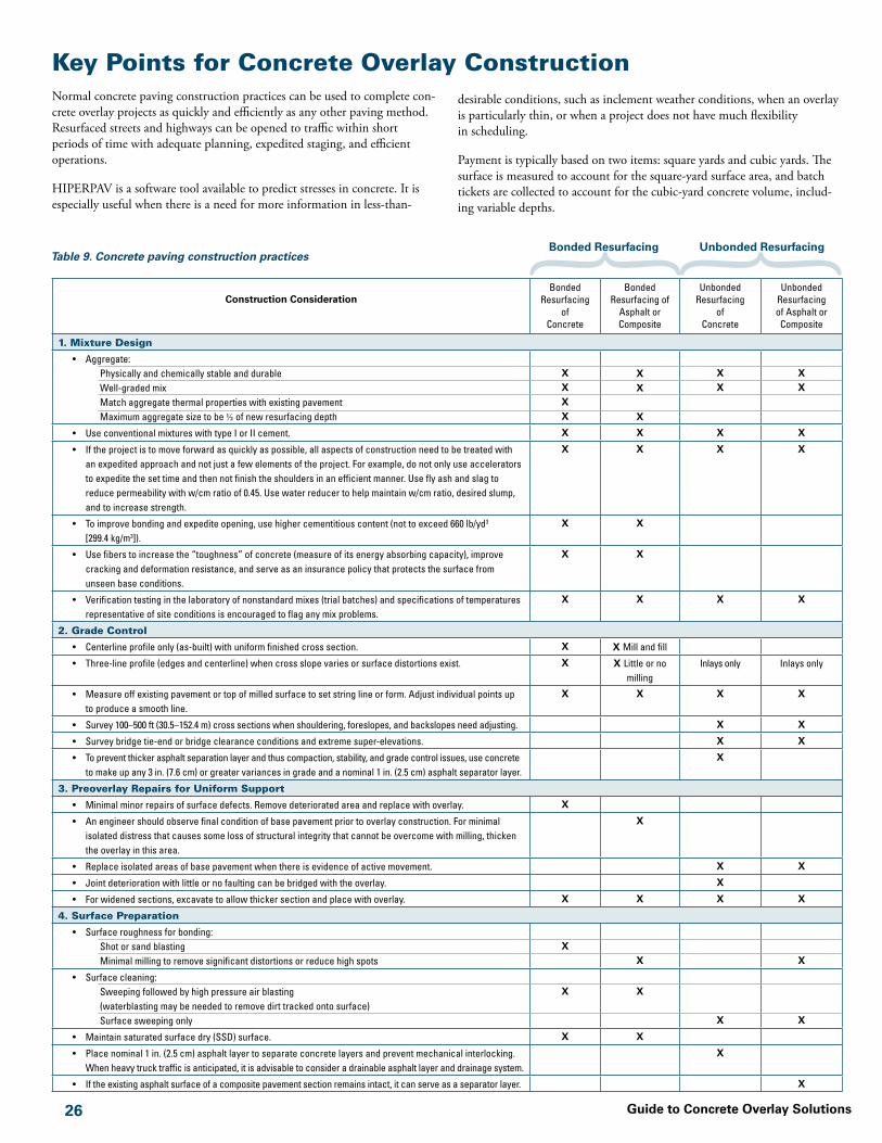
�� Guide to Concrete Overlay Solutions
Key Points for Concrete Overlay ConstructionNormal concrete paving construction practices can be used to complete con-crete overlay projects as quickly and efficiently as any other paving method. Resurfaced streets and highways can be opened to traffic within short periods of time with adequate planning, expedited staging, and efficient operations.
HIPERPAV is a software tool available to predict stresses in concrete. It is especially useful when there is a need for more information in less-than-
Construction ConsiderationBonded
Resurfacing of
Concrete
Bonded Resurfacing of
Asphalt or Composite
Unbonded Resurfacing
of Concrete
Unbonded Resurfacing of Asphalt or Composite
1. Mixture Design
• Aggregate:Physically and chemically stable and durableWell-graded mix Match aggregate thermal properties with existing pavementMaximum aggregate size to be ½ of new resurfacing depth
XXXX
XX
X
XX
XX
• Use conventional mixtures with type I or II cement. X X X X
• If the project is to move forward as quickly as possible, all aspects of construction need to be treated with an expedited approach and not just a few elements of the project. For example, do not only use accelerators to expedite the set time and then not finish the shoulders in an efficient manner. Use fly ash and slag to reduce permeability with w/cm ratio of 0.45. Use water reducer to help maintain w/cm ratio, desired slump, and to increase strength.
X X X X
• To improve bonding and expedite opening, use higher cementitious content (not to exceed 660 lb/yd3 [299.4 kg/m3]).
X X
• Use fibers to increase the “toughness” of concrete (measure of its energy absorbing capacity), improve cracking and deformation resistance, and serve as an insurance policy that protects the surface from unseen base conditions.
X X
• Verification testing in the laboratory of nonstandard mixes (trial batches) and specifications of temperatures representative of site conditions is encouraged to flag any mix problems.
X X X X
2. Grade Control
• Centerline profile only (as-built) with uniform finished cross section. X X Mill and fill
• Three-line profile (edges and centerline) when cross slope varies or surface distortions exist. X X Little or no milling
Inlays only Inlays only
• Measure off existing pavement or top of milled surface to set string line or form. Adjust individual points up to produce a smooth line.
X X X X
• Survey 100–500 ft (30.5–152.4 m) cross sections when shouldering, foreslopes, and backslopes need adjusting. X X
• Survey bridge tie-end or bridge clearance conditions and extreme super-elevations. X X
• To prevent thicker asphalt separation layer and thus compaction, stability, and grade control issues, use concrete to make up any 3 in. (7.6 cm) or greater variances in grade and a nominal 1 in. (2.5 cm) asphalt separator layer.
X
3. Preoverlay Repairs for Uniform Support
• Minimal minor repairs of surface defects. Remove deteriorated area and replace with overlay. X
• An engineer should observe final condition of base pavement prior to overlay construction. For minimal isolated distress that causes some loss of structural integrity that cannot be overcome with milling, thicken the overlay in this area.
X
• Replace isolated areas of base pavement when there is evidence of active movement. X X
• Joint deterioration with little or no faulting can be bridged with the overlay. X
• For widened sections, excavate to allow thicker section and place with overlay. X X X X
4. Surface Preparation
• Surface roughness for bonding:Shot or sand blastingMinimal milling to remove significant distortions or reduce high spots
XX
X
• Surface cleaning:Sweeping followed by high pressure air blasting (waterblasting may be needed to remove dirt tracked onto surface)Surface sweeping only
X X
X X
• Maintain saturated surface dry (SSD) surface. X X
• Place nominal 1 in. (2.5 cm) asphalt layer to separate concrete layers and prevent mechanical interlocking. When heavy truck traffic is anticipated, it is advisable to consider a drainable asphalt layer and drainage system.
X
• If the existing asphalt surface of a composite pavement section remains intact, it can serve as a separator layer. X
desirable conditions, such as inclement weather conditions, when an overlay is particularly thin, or when a project does not have much flexibility in scheduling.
Payment is typically based on two items: square yards and cubic yards. The surface is measured to account for the square-yard surface area, and batch tickets are collected to account for the cubic-yard concrete volume, includ-ing variable depths.
Bonded Resurfacing Unbonded ResurfacingTable 9. Concrete paving construction practices

�7Guide to Concrete Overlay Solutions
Construction ConsiderationBonded
Resurfacing ofConcrete
Bonded Resurfacing of
Asphalt or Composite
Unbonded Resurfacing
of Concrete
Unbonded Resurfacing of Asphalt or Composite
5. Concrete Placement
• When the surface temperature of the asphalt is at or above 120°F (48.9°C), surface watering can be used to reduce the temperature and minimize the potential for shrinkage cracking. No standing water should remain at the time the overlay is placed.
X X X
• The bonding of the resurfacing can be affected by the climatic conditions at the time of placement. Significant stresses that develop due to rapid changes in temperature, humidity, and wind speed may cause debonding under severe conditions. HIPERPAV can predict interface bond stress based on numerous factors.
X X
• Feeding concrete consistently into the paver requires an adequate number of batch delivery trucks. The number of trucks will often dictate the slip-form or placement speed. The entire cycle of mixing, discharging, traveling, and depositing concrete must be coordinated for the mixing plan capacity, hauling distance, and spreader and paving machine capabilities. Extra trucks may be needed as the haul time increases.
X X X X
• Do not track paste or dirt onto the existing surface ahead of the paver because it can cause debonding. X X
• The manner in which the crew deposits concrete in front of the paving operation is an important factor for creating a smooth pavement surface in resurfacing projects. Placement in front of slip-form paver should be done in small overlapping piles so as to minimize lateral movements.
X X X X
• Properly established, secure, and maintained string line is very important to smoothness; constant and continuous paving prevents interruptions that lead to bumps.
X X X X
• No use of dowels or lane ties is required. X X
• When dowel bars are used, they should be located approximately in the mid-third of the overlay. Isolated thicker sections should not dictate a change in basket height or DBI insertion depth.
X X
• Texturing needs to be performed at the right time so as not to disturb setting of the concrete. Shallow longitudinal tining or burlap/turf are two effective textures. Burlap/turf drag have shown adequate friction with a quiet surface when hard sands are used in the mix.
X X X X
6. Curing to Prevent Rapid Loss of Water from the Concrete
• HIPERPAV is a useful tool for predicting the effect of various curing techniques. It can model the design, materials, construction, and environmental conditions affecting the concrete during early age.
X X X X
• Proper curing of bonded resurfacing is particularly important because they are thin with large surface areas compared with the volume of concrete. The curing rate may be increased 1.5 to 2 times the normal rate to provide additional protection.
X X
• During hot weather, steps should be taken to reduce the evaporation rate from the concrete. For significant evaporation, provide a more effective curing application, such as fog spraying, or apply an approved evaporation reducer.
X X X X
• Adequate curing of overlays on a stiff support system (especially on underlying concrete pavement) is important to minimize curling and warping stresses.
X
• A single coat of liquid curing compound provides the normal protection, as long as the finished product appears as a uniformly painted solid white surface with no blotchy appearance.
X X
7. Joints
• Joint spacing for concrete overlays requires special consideration for each type:Joints are typically mismatched to maximize load transfer from the underlying pavement. However, some
states that have not intentionally mismatched joints have not experienced any adverse effects.Joint panel spacings are very short to reduce shear stress and reduce curling and warp stress.Mismatched joint spacing with the underlying pavement is typical to improve load transfer. Because of
the potential for higher curling and warping stress from a rigid underlining pavement, shorter than normal spacing is typical in unbonded resurfacing of concrete pavements.
X
XX
• Joint sawing:The timing of sawing is critical. Sawing joints too early can cause excess raveling. HIPERPAV may be
useful in helping to predict the appropriate time window for joint sawing, based on the concrete mix design, construction times, and environmental conditions.
Sawing must be completed before curl stresses exceed the bond strength developed.Sawing too late can cause excess stresses, leading to uncontrolled random cracking.Transverse joint saw-cut depth for conventional saws.
Transverse joint saw-cut depth for early-entry saws.
Longitudinal joint saw-cut depth.
X
XX
full depth + ½ in. (�.� cm)
full depth + ½ in. (�.� cm)
T/� (at least)
X
XX
T/�
Not < �¼ in. (�.� cm)
T/�
X
X
X
X
• Joint seals:No seal optionStandard practiceLow-modulus hot-pour sealant with narrow joint
XX
X X
X
X
X
Bonded Resurfacing Unbonded Resurfacing
T/� min.–T/� max.
Not < �¼ in. (�.� cm)
T/�
Table 9. Concrete paving construction practices, continued

Guide to Concrete Overlay Solutions ��
ACI Committee 325. 2006. Concrete Overlays for Pavement Rehabilitation. Publication ACI 325.13R-06. Farmington Hills, MI: American Concrete Institute.
ACPA. 1990a. Guidelines for Bonded Concrete Overlays. Technical Bulletin TB-007P. Skokie, IL: American Concrete Pavement Association.
———. 1990b. Guidelines for Unbonded Concrete Overlays. Technical Bulletin TB-005P. Skokie, IL: American Concrete Pavement Association.
———. 1991b. Guidelines for Concrete Overlays of Existing Asphalt Pavements (Whitetopping). Technical Bulletin TB-009P. Skokie, IL: American Concrete Pavement Association.
———. 1998. Whitetopping—State of the Practice. Engineering Bulletin EB210.02P. Skokie, IL: American Concrete Pavement Association.
———. 1999a. Construction Specification Guideline for Ultra-Thin Whitetopping. Information Series IS120P. Skokie, IL: American Concrete Pavement Association.
———. 1999b. Ultra-Thin Whitetopping. Information Series IS100.02P. Skokie, IL: American Concrete Pavement Association.
———. 2000. Repair of Ultra-Thin Whitetopping: Roadways and Airfields. Publication PA397P. Skokie, IL: American Concrete Pavement Association.
AASHTO. 1993. Guide for Design of Pavement Structures. Washington, DC: American Association of State Highway and Transportation Officials.
AASHTO. 1998. Supplement to the AASHTO Guide for Design of Pavement Structures. Washington, DC: American Association of State Highway and Transportation Officials.
Anderson, S.D., G.L. Ullman, and B.C. Blaschke. 2002. A Process for Selecting Strategies for Rehabilitation of Rigid Pavements. NCHRP Project 10-50A. Washington, DC: Transportation Research Board.
Cable, J.K., M.L. Anthony, F.S. Fanous, and B.M. Phares. 2006. Evaluation of Composite Pavement Unbonded Overlays. IHRB Project TR-478. Ames, IA: Iowa State University.
Cable, J.K., L.E. Edgar, and D.R. Anderson. 2005. Ultra-Thin Portland Cement Concrete Overlay Extended Evaluation. IHRB Project TR-432. Ames, IA: Iowa State University.
Cable, J.K., F.S. Fanous, H. Ceylan, D. Wood, D. Frentress, T. Tabbert, S.-Y. Oh, and K. Gopalakrishnan. 2005. Design and Construction Procedures for Concrete
SourcesOverlay and Widening of Existing Pavements. IHRB Project TR-511. Ames, IA: Iowa State University.
Cable, J.K., J.M. Hart, and T.J. Ciha. 2001. Thin Bonded Overlay Evaluation. IHRB Project HR-559. Ames, IA: Iowa State University.
Delatte, N., S. Chen, J. Davidson, A. Sehdev, N. Amer, and M. Endfinger. 2001. Design and Quality Control of Concrete Overlays. UTCA Report 01220. Tuscaloosa, AL: University Transportation Center for Alabama.
ERES Consultants. 1999. Evaluation of Unbonded Portland Cement Concrete Overlays. NCHRP Report 415. Washington, DC: Transportation Research Board.
FHWA. 2002a. Conventional Whitetopping Overlays. Technical Brief. FHWA-IF-03-008. Washington, DC: Federal Highway Administration.
———. 2002b. Unbonded Portland Cement Concrete Overlays. Technical Brief. FHWA-IF-03-006. Washington, DC: Federal Highway Administration.
Hall, K.T., C.E. Correa, S.H. Carpenter, and R.P. Elliott. 2001. Rehabilitation Strategies for Highway Pavements. NCHRP Project C1-38. Washington, DC: Transportation Research Board.
Mack, J.W., L.D. Hawbaker, and L.W. Cole. 1998. Ultrathin Whitetopping: State-of-the-Practice for Thin Concrete Overlays of Asphalt. Transportation Research Record 1610:39–43.
McGhee, K.H. 1994. Portland Cement Concrete Resurfacing. NCHRP Synthesis of Highway Practice 204. Washington, DC: Transportation Research Board.
NCHRP. 2004. Guide for Mechanistic-Empirical Design of New and Rehabilitated Pavements. NCHRP Project 1-37a. Washington, DC: Transportation Research Board.
NCHRP. 2005. Versions 0.900 and 1.0 of the M-E Pavement Design Software. NCHRP Project 1-40A. Washington, DC: Transportation Research Board.
NCHRP. 2006. Technical Assistance to NCHRP and NCHRP Project 1-40a. NCHRP Project 1-40d. Washington, DC: Transportation Research Board.
Rasmussen, R.O., and D.K. Rozycki. 2004. Thin and Ultra-Thin Whitetopping. NCHRP Synthesis of Highway Practice 338. Washington, DC: Transportation Research Board.
Riley, R.C., A. Gotlif, and J. Mallela. 2005a. Whitetopping: Atypical is Typical. Proceedings of the International Conference on Best Practices for Ultrathin
Future Repairs
and Thin Whitetoppings. Denver, CO, April 12–15, 2005. Skokie, IL: American Concrete Pavement Association.
Riley, R.C., L. Titus-Glover, J. Mallela, S. Waalkes, and M. Darter. 2005b. Incorporation of Probabilistic Concepts into Fatigue Analysis of Ultrathin Whitetopping as Developed for the American Concrete Pavement Association. Proceedings of the International Conference on Best Practices for Ultrathin and Thin Whitetoppings. Denver, CO, April 12–15, 2005. Skokie, IL: American Concrete Pavement Association.
Sheehan, M.J., S.M. Tarr, and S.D. Tayabji. 2004. Instrumentation and Field Testing of Thin Whitetopping Pavements in Colorado and Revision of the Existing Colorado Thin Whitetopping Procedure. Report CDOT-DTD-R-2004-12. Denver, CO: Colorado Department of Transportation.
Smith, K.D., H.T. Yu, and D.G. Peshkin. 2002. Portland Cement Concrete Overlays: State of the Technology Synthesis. Publication FHWA-IF-02-045. Washington, DC: Federal Highway Administration.
Tarr, S.M., M.J. Sheehan, and P.A. Okamoto. 1998. Guidelines for the Thickness Design of Bonded Whitetopping Pavements in the State of Colorado. Report CDOT-DTD-R-98-10. Denver, CO: Colorado Department of Transportation.
Trevino, M., B.F. McCullough, and D.W. Fowler. 2004. Techniques and Procedures for Bonded Concrete Overlays. Report FHWA/TX-05/0-4398-2. Austin, TX: Center for Transportation Research, University of Texas at Austin.
Titus-Glover, L., J. Mallela, M.I. Darter, G. Voigt, and S. Waalkes. 2005. Enhanced Portland Cement Concrete Fatigue Model for StreetPave: Rigid and Flexible Pavement Design 2005. Transportation Research Record 1919:29–37.
Vandenbossche, J.M., and A.J. Fagerness. 2002. Performance, Analysis, and Repair of Ultrathin and Thin Whitetopping at Minnesota Road Research Facility. Transportation Research Record 1809:191–198.
Winkelman, T.J. 2002. Bonded Concrete Overlay Performance in Illinois. Report FHWA/IL/PRR 143. Springfield, IL: Illinois Department of Transportation.
Wu, C.-L., S.M. Tarr, T.M. Refai, M.A. Nagi, and M.J. Sheehan. 1999. Development of Ultra-Thin Whitetopping Design Procedure. PCA R&D Serial 2124. Skokie, IL: Portland Cement Association.
Repairing concrete overlays is easier than repair-ing a section of conventional pavement. If a panel is distressed but the ride quality of the pavement is not compromised, the panel should be left in place.
If a ride quality problem develops, the panel or an isolated area should be replaced before any pieces of concrete become loose from the overlay.Thin overlays constructed without reinforcement can easily be milled out and replaced with a new
concrete surface. Utility repair locations can be restored to original surface elevation and ride quality with ease. Do not patch with asphalt, because the adjacent concrete panels will move and break the bond.


National Concrete Pavement Technology CenterIowa State University
2711 South Loop Drive, Suite 4700Ames, IA 50010-8664
515-294-5798www.cptechcenter.org
ACPA publication TB021P
Iowa State University’s Center for Transportation Research and Education is the umbrella organization for the following centers and programs: Bridge Engineering Center • Center for Weather Impacts on Mobility
and Safety • Construction Management & Technology • Iowa Local Technical Assistance Program • Iowa Traffic Safety Data Service • Midwest Transportation Consortium • National Concrete Pavement
Technology Center • Partnership for Geotechnical Advancement • Roadway Infrastructure Management and Operations Systems • Statewide Urban Design and Specifications • Traffic Safety and Operations