Embed Size (px)
Citation preview

Guide to Bridge Standard Drawings August 2017 Bridge Division

Guide to Bridge Standard Drawings TxDOT 08/2017 2
Table of Contents
About this Guide ........................................................................................................................ 3
Pretensioned Concrete I-Beam Bridge Standard Drawings ................................................... 6
Pretensioned Concrete I-Girder Bridge Standard Drawings ................................................... 7
Pretensioned Concrete Slab Beam Bridge Standard Drawings ........................................... 12
Pretensioned Concrete Decked Slab Beam Bridge Standard Drawings ............................. 17
Pretensioned Concrete Box Beam Bridge Standard Drawings ............................................ 21
Pretensioned Concrete Spread Box Beams (X-Beams) Bridge Standard Drawings ........... 25
Cast-in-Place Concrete Slab and Girder (Pan Form) Bridge Standard Drawings ................ 29
Cast-in-Place Concrete Slab Span Bridge Standard Drawings ............................................ 32
Steel Beam Bridge Standard Drawings ................................................................................. 35

Guide to Bridge Standard Drawings TxDOT 08/2017 3
About this Guide
Purpose & Audience This document provides quick-reference information to guide bridge designers who are working for the Texas Department of Transportation (TxDOT) in the use of bridge standard drawings, which are posted on the TxDOT web site: http://www.dot.state.tx.us/insdtdot/orgchart/cmd/cserve/standard/bridge-e.htm.
Document History This Document is subject to revision as new guidelines are documented and as conditions, experience, and research data warrant. Revisions are summarized in the following table, and text that has been added or changed since the previous version in green.
Publication Date Summary of Changes
June 2003 Initial release: Published guidelines for use of standard drawings for prestressed concrete slab beams.
November 2003
Revision adding information on cast-in-place concrete slab span bridge standard drawings.
August 2004 Revision updating existing information and adding information on steel beam bridge standard drawings.
January 2005 Revision adding information on prestressed concrete I-beam bridge standard drawings.
October 2005 Revision adding information on concrete slab and girder (pan form) span bridge standard drawings.
January 2006 Revision adding information on prestressed concrete double-T beam bridge standard drawings.
March 2007 Revision adding information for prestressed concrete box beams standard drawings.
April 2008 Revision adding information on decked slab beams.

Guide to Bridge Standard Drawings TxDOT 08/2017 4
September 2010
Revision adding information regarding I-girder bridge standard drawings.
June 2011 Revision adding information regarding X-beam bridge standard drawings.
August 2011 Revision deleting information for double-T beams and retiring standard drawings of same effective August 2011. Revision amending the Standard Drawing Features of the Concrete Slab and Girder (Pan Form) Bridge Standard Drawings. Revision amending the Description of Component of the Prestressed Concrete Slab Beam Bridge Standard Drawings.
September 2013
Revision to add new miscellaneous standard drawings. Revision adding restrictions on use.
October 2015 Revision retiring I-Beam Standard drawings effective November 2014. Revision to I-Girder standard drawings increasing slab depth from 8 in. to 8 ½ in. Revision to Box Beams Standard to include removal of BBSDO, SBBO, BBRAO, BBPT & removal of ACP (Asphaltic Concrete pavement).
March 2016 Revision adding information to accommodate T221P, T224 and SSPC standard drawings.
April 2017 Revision adding information to accommodate Prestressed, Precast Bent Cap Option for round columns standard drawing (PPBC-RC) standard drawing.
August 2017 Revision to I-Girder Standard to add PCP(O) and PCP(O)-FAB.

Guide to Bridge Standard Drawings TxDOT 08/2017 5
Feedback Any questions or comments on the content contained in this document can be directed to the Director of the Bridge Division, Texas Department of Transportation.

Guide to Bridge Standard Drawings TxDOT 08/2017 6
Pretensioned Concrete I-Beam Bridge Standard Drawings
Note All standard drawings for I-Beams are retired effective November 2014.

Guide to Bridge Standard Drawings TxDOT 08/2017 7
Pretensioned Concrete I-Girder Bridge Standard Drawings
Advantages/ Usefulness
Pretensioned concrete I-Girders are useful for bridges with skewed substructure, when substructure depth is not restricted, and where future widening is anticipated.
Pretensioned concrete I-Girder bridges cost less than all other standard bridge types.
Standard Drawing Location
IG prefixes Website:
http://www.dot.state.tx.us/insdtdot/orgchart/cmd/cserve/standard/bridge-e.htm#IGirders
Standard Drawing Features
Designed for HL93 live load in accordance with AASHTO LRFD Bridge
Design Specifications. Drawings accommodate:
Tx28, Tx34, Tx40, Tx46, Tx54, and Tx62 24-, 28-, 30-, 32-, 38-, 40-, and 44-ft. roadway widths 0-, 15-, 30-, and 45-degree skew angles. Span lengths of 40 ft. through 135 ft. in 5 ft. increments. Not all
girder types accommodate all span lengths. Abutment header slopes of 2:1 and 3:1. Most standard rail types.
Roadway surface is a cast-in-place concrete slab with 8 ½ -in. depth. Details are provided to construct 2 or 3 span units with slabs
continuous over interior bents. Using units reduces the number of expansion joints.
Drawings support these foundation options: Drilled shafts (36-and 42-in) Multi-pile footings Prestressed concrete piling (18-,20-,24-in) Steel H-piling (HP 14x117 and HP 18x135)
Drawings provide details for drilled shafts and multi-pile footings only for interior bents for Tx62 girders.
Seven standard drawings are provided to use with customized bridge plans.
Standard Drawings Needed for Bridge Details
IGSD – Roadway specific Prestressed Concrete I-Girder standard
drawing AIG – Girder, roadway and skew specific Abutment standard
drawings BIG – Girder, roadway and skew specific Interior Bent standard
drawing or; BTIG for interior Trestle Bent standard drawings
Guide to Bridge Standard Drawings TxDOT 08/2017 8
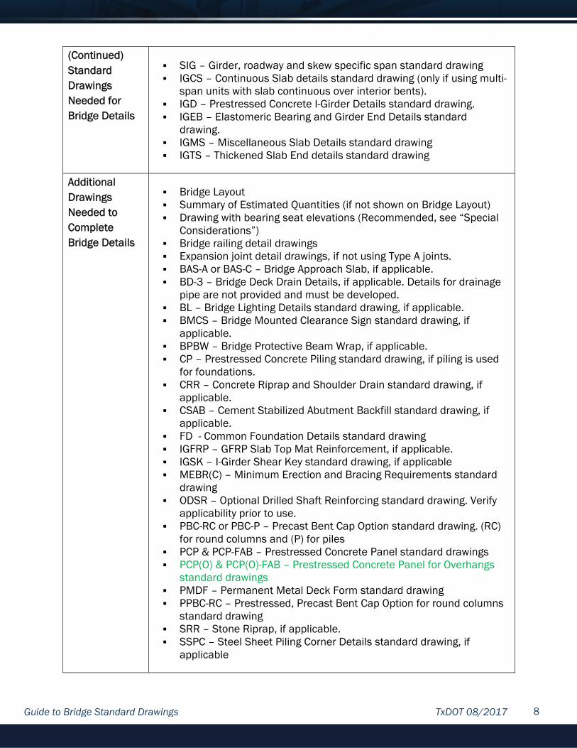
(Continued) Standard Drawings Needed for Bridge Details
SIG – Girder, roadway and skew specific span standard drawing IGCS – Continuous Slab details standard drawing (only if using multi-
span units with slab continuous over interior bents). IGD – Prestressed Concrete I-Girder Details standard drawing. IGEB – Elastomeric Bearing and Girder End Details standard
drawing. IGMS – Miscellaneous Slab Details standard drawing IGTS – Thickened Slab End details standard drawing
Additional Drawings Needed to Complete Bridge Details
Bridge Layout Summary of Estimated Quantities (if not shown on Bridge Layout) Drawing with bearing seat elevations (Recommended, see “Special
Considerations”) Bridge railing detail drawings Expansion joint detail drawings, if not using Type A joints. BAS-A or BAS-C – Bridge Approach Slab, if applicable. BD-3 – Bridge Deck Drain Details, if applicable. Details for drainage
pipe are not provided and must be developed. BL – Bridge Lighting Details standard drawing, if applicable. BMCS – Bridge Mounted Clearance Sign standard drawing, if
applicable. BPBW – Bridge Protective Beam Wrap, if applicable. CP – Prestressed Concrete Piling standard drawing, if piling is used
for foundations. CRR – Concrete Riprap and Shoulder Drain standard drawing, if
applicable. CSAB – Cement Stabilized Abutment Backfill standard drawing, if
applicable. FD - Common Foundation Details standard drawing IGFRP – GFRP Slab Top Mat Reinforcement, if applicable. IGSK – I-Girder Shear Key standard drawing, if applicable MEBR(C) – Minimum Erection and Bracing Requirements standard
drawing ODSR – Optional Drilled Shaft Reinforcing standard drawing. Verify
applicability prior to use. PBC-RC or PBC-P – Precast Bent Cap Option standard drawing. (RC)
for round columns and (P) for piles PCP & PCP-FAB – Prestressed Concrete Panel standard drawings PCP(O) & PCP(O)-FAB – Prestressed Concrete Panel for Overhangs
standard drawings PMDF – Permanent Metal Deck Form standard drawing PPBC-RC – Prestressed, Precast Bent Cap Option for round columns
standard drawing SRR – Stone Riprap, if applicable. SSPC – Steel Sheet Piling Corner Details standard drawing, if
applicable

Guide to Bridge Standard Drawings TxDOT 08/2017 9
Restrictions on Use of Standard Drawings
Do not change girder type (for example, Tx28 to Tx40) within a
bridge; transition bent details are not provided. Maximum allowed column height, allowed exposed pile height, and
maximum allowed pile loads are listed on bent details. Do not use rail types T66, T80HT, T80SS, C412, C66, or T224. Their
width or weight precludes their use on standard roadway width spans.
Do not change skew angle within a bridge. Use issued substructure details only with issued span details. The maximum number of spans per unit is three, and the maximum
unit length cannot exceed the limits shown on standard drawing IGCS.
Some unit lengths are too great to use sealed or open armor joints and Type A joints.
Do not use single-sided crash cushions (see Design Division standard drawing SSCC-03A) with abutment wingwalls lengths less than 7 ft.
Drawings do not accommodate raised sidewalks and medians or rails not on edge of slab. If adding a raised sidewalk, median or rail, check standard drawing for additional loading.
NOTE: Some restrictions may be overcome by modifying the standard drawings with appropriate additional details and information. Denote modified details as MOD in the title block, and clearly indicate which drawings must be signed, sealed and dated by a registered Professional Engineer.
Special Considerations
If girder slope exceeds 5%, standard drawing IGED requires beveled
steel sole plates be used at bearings. Sole plates add 1-inch to the section depth which will need to be accounted for in bearing seat elevation calculations. Modify abutment standard for the extra section depth accordingly, if applicable.
If Prestressed Concrete Panel for Overhangs (PCP(O) and PCP(O)-FAB) standard details are used, the minimum haunch is 1” at mid span which will need to be accounted for in bearing sear elevation calculations. Modify abutment standard for the extra section depth accordingly, if applicable.
As a check to the Contractor’s calculated elevations, provide bearing seat elevations in the plan if a roadway vertical curve is located on the structure (recommended). If an adjustment is made to the section depth (to accommodate a sag vertical curve), note the section depth adjustment used along with the bearing seat elevations.

Guide to Bridge Standard Drawings TxDOT 08/2017 10
(Continued) Special Considerations
Spreadsheet STD-BRG.xls, available from the Bridge Division, is a
tool to help calculate and generate bearing seat elevations. It also generates girder slopes, which can be provided with the bearing elevations to aid the bearing pad fabricator. This spreadsheet does not consider Prestressed Concrete Panel for Overhangs (PCP(O) and PCP(O)-FAB).
If the presence of a roadway vertical curve forces a haunch depth greater than 3 ½ in. at any point on a girder, reinforce the haunch as instructed by standard drawing IGMS. If Prestressed Concrete Panels are used as a forming option, find this haunch reinforcement on standard drawing PCP.
Do not use open bridge rails – such as T223, T552, etc. – when frequent use of de-icing agents is anticipated. If deck drainage is desired and de-icing agent use is predicted, use the drain details shown on standard IGMS. Locate the drain locations on the Bridge Layout (no closer than 4 ft. from centerline of the substructure caps.)
On substructure standard drawings, dowel bars D are noted to be excluded at ends of units. Therefore, if continuous slab units are indicated on the bridge layout and standard drawing IGCS is included in the plans, do not use dowels at unit end (expansion joint locations).
If using interior trestle bents (standard drawing prefix BTIG), note limitations on pile load and exposed pile heights when selecting a pile type and size.
Quantities provided for reinforcing steel weight are not bid items. They are provided for Contractor’s information only.
Adjust bent concrete quantities as needed for column heights shown on the Bridge Layout. Adjust abutment concrete quantities if not using approach slabs. See substructure standard drawings for guidance.
The Prestressed, Precast Bent Cap Option for round columns (PPBC-RC) standard drawing only provides pedestal details for non-skewed bents and pedestals up to 18 inches tall. Provide details for pedestals on skewed bents. In addition, if shear keys are required, provide shear key details considering strand location, column location, and shear key reinforcement.
Specific Bridge Layout Requirements
Label all girder ends with a “D” except when using multi-span units.
With units, do not label girder ends “D” at expansion joint locations. List unit lengths if not locating expansion joints at each bent. For
continuous slabs, see details and notes on span standard drawings and standard IGCS; two- or three-span units are conditionally permitted.

Guide to Bridge Standard Drawings TxDOT 08/2017 11
(Continued) Specific Bridge Layout Requirements
Verify that column or exposed pile heights do not exceed values
listed on bent standard drawings. These maximum heights must be evaluated by the Engineer in areas of soft soil or where scour is anticipated.
Indicate abutment wingwall foundations if required. See Abutment standard drawings for wingwall foundation requirements based on girder type and header slope.
Recommended expansion joints in order of preference are 4-in. sealed expansion joints (see standard drawing SEJ-A), sealed armor joints (see standard drawing AJ), and Type A joints (see standard drawing IGMS). Type A joints and open armor joints are not recommended for On-System structures. Type A joints are recommended for bridges with low traffic volumes only. Do not place Type A joints more than 100 ft. apart for proper joint performance.

Guide to Bridge Standard Drawings TxDOT 08/2017 12
Pretensioned Concrete Slab Beam Bridge Standard Drawings
Advantages/ Usefulness
Pretensioned concrete slab beams are useful for bridges needing
shallow superstructures and fast construction. Pretensioned concrete slab beam bridges cost more than pretensioned
concrete I-Girder bridges and cost less than pretensioned concrete box beam bridges.
Construction is similar to pretensioned concrete box beam bridges. Slab beams do not have shear keys therefore must be topped with a
cast-in-place concrete slab to ensure that beams act in unison.
Standard Drawing Location
PSB prefixes. Web site:
http://www.dot.state.tx.us/insdtdot/orgchart/cmd/cserve/standard/bridge-e.htm#SlabBeams
Standard Drawing Features
Designed for HL93 live load in accordance with AASHTO LRFD Bridge
Design Specifications. Drawings accommodate
24-, 28-, and 30-ft. roadway widths. 0-, 15-, and 30-degree skew angles. With SB12 beams, drawings accommodate span lengths of 25 ft.
through 40 ft. in 5-ft. increments. Maximum superstructure depth with SB12 beams is 18.5 in., which accounts for beam camber and dead-load deflection.
With SB15 beams, drawings accommodate span lengths of 25 ft. through 50 ft. in 5-ft. increments. Maximum superstructure depth with SB15 beams is 22 in., which accounts for beam camber and dead-load deflection.
Abutment header slopes of 2:1 and 3:1 Most standard rail types
Roadway surface is a cast-in-place concrete slab with a 5-in. minimum depth.
Details are provided to construct 2 or 3 span units with slabs continuous over interior bents. Using units reduces the number of expansion joints. Drawings support these foundation options: Drilled shafts (24-in) Prestressed concrete piling (16- and 18-in.) Steel H-piling (HP14x73 and HP14x117).
Seven standard drawings are provided to use with customized bridge plans.

Guide to Bridge Standard Drawings TxDOT 08/2017 13
Standard Drawings Needed for Bridge Details
APSB - Roadway and skew-specific Abutment standard drawing. Some
skewed abutment standard drawings are foundation-specific (for example, drilled shafts and pilings).
BPSB – Roadway and skew-specific Interior Bent Standard drawing SPSB – Roadway and skew-specific span standard drawing. PSB – Appropriate Prestressed Concrete Slab Beam standard drawing PSBEB – Elastomeric Bearing standard drawing PSBRA – Rail Anchorage standard drawing PSBSD – Prestressed Concrete Slab Beam Standard Design standard
drawing
Additional Drawings Needed to Complete Bridge Details
Bridge Layout Summary of Estimated Quantities (if not shown on the Bridge Layout). Bridge railing detail drawings Expansion joint detail drawings, if not using Type A joints. BAS-A or BAS-C – Bridge Approach Slab standard drawing, if applicable. BMCS – Bridge Mounted Clearance Sign standard drawing, if applicable. BPBW – Bridge Protective Beam Wrap, if applicable. CP – Prestressed Concrete Piling standard drawing if piling is the
foundation type. CRR – Concrete Riprap and Should Drains standard drawing, if
applicable. CSAB – Cement Stabilized Abutment Backfill standard drawing, if
applicable. FD – Common Foundation Details standard drawing ODSR – Optional Drilled Shaft Reinforcing standard drawing. Verify
applicability prior to use. PBC-RC or PBC-P – Precast Bent Cap Option standard drawing. (RC) for
round columns or (P) for piles. PPBC-RC – Prestressed, Precast Bent Cap Option for round columns
standard drawing SRR – Stone Riprap, if applicable. SSPC – Steel Sheet Piling Corner Details standard drawing, if applicable
Restrictions on Use of Standard Drawings
Do not change roadway cross slope on bridges. Roadway vertical curves
may not be used on bridges with skewed supports. Calculations required for determining top-of-cap elevations and bearing pad dimensions with these conditions are beyond the scope of these drawings. Roadway vertical curves are allowed on bridges without skewed supports.
Skew angle is limited to 30 degrees. Do not change beam type (such as SB12 to SB15) within a bridge;
transition bent details are not provided. Maximum allowed column height, allowed exposed pile heights, and
maximum allowed pile loads are listed on bent details.
Guide to Bridge Standard Drawings TxDOT 08/2017 14
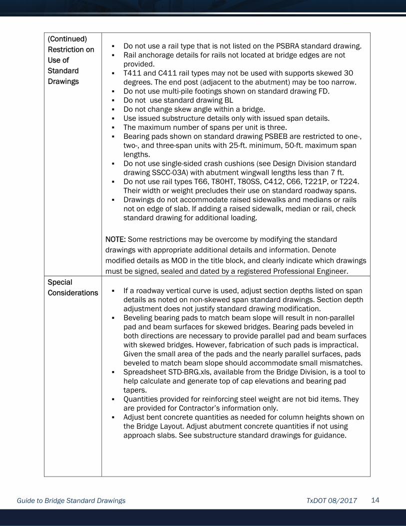
(Continued) Restriction on Use of Standard Drawings
Do not use a rail type that is not listed on the PSBRA standard drawing. Rail anchorage details for rails not located at bridge edges are not
provided. T411 and C411 rail types may not be used with supports skewed 30
degrees. The end post (adjacent to the abutment) may be too narrow. Do not use multi-pile footings shown on standard drawing FD. Do not use standard drawing BL Do not change skew angle within a bridge. Use issued substructure details only with issued span details. The maximum number of spans per unit is three. Bearing pads shown on standard drawing PSBEB are restricted to one-,
two-, and three-span units with 25-ft. minimum, 50-ft. maximum span lengths.
Do not use single-sided crash cushions (see Design Division standard drawing SSCC-03A) with abutment wingwall lengths less than 7 ft.
Do not use rail types T66, T80HT, T80SS, C412, C66, T221P, or T224. Their width or weight precludes their use on standard roadway spans.
Drawings do not accommodate raised sidewalks and medians or rails not on edge of slab. If adding a raised sidewalk, median or rail, check standard drawing for additional loading.
NOTE: Some restrictions may be overcome by modifying the standard drawings with appropriate additional details and information. Denote modified details as MOD in the title block, and clearly indicate which drawings must be signed, sealed and dated by a registered Professional Engineer.
Special Considerations
If a roadway vertical curve is used, adjust section depths listed on span
details as noted on non-skewed span standard drawings. Section depth adjustment does not justify standard drawing modification.
Beveling bearing pads to match beam slope will result in non-parallel pad and beam surfaces for skewed bridges. Bearing pads beveled in both directions are necessary to provide parallel pad and beam surfaces with skewed bridges. However, fabrication of such pads is impractical. Given the small area of the pads and the nearly parallel surfaces, pads beveled to match beam slope should accommodate small mismatches.
Spreadsheet STD-BRG.xls, available from the Bridge Division, is a tool to help calculate and generate top of cap elevations and bearing pad tapers.
Quantities provided for reinforcing steel weight are not bid items. They are provided for Contractor’s information only.
Adjust bent concrete quantities as needed for column heights shown on the Bridge Layout. Adjust abutment concrete quantities if not using approach slabs. See substructure standard drawings for guidance.

Guide to Bridge Standard Drawings TxDOT 08/2017 15
(Continued) Special Considerations
Earwalls are incorporated into abutments and interior bents for lateral
restraint of the superstructure: exterior beams bear against the earwalls with a ½-inch layer of preformed bituminous fiber material between beam and earwall. It may be difficult to ensure that beams fit within the earwalls or bear against them due to fabrication and construction tolerances and lateral translation of beams on neoprene bearings resulting from roadway cross-slope. Therefore, substructure details provide a permissible construction joint so that earwalls can be cast after beams are set, using the beams as a form. If earwalls are cast prior to beam placement, their inside face must be cast perpendicular to the top of cap to ensure parallelism with beams.
The Prestressed, Precast Bent Cap Option for round columns (PPBC-RC) standard drawing does not provide details for ear walls. See the bent details for earwall details.
Do not use Asphalt Concrete Pavement (ACP) topping for slab beams in lieu of a 5-inch concrete slab because of the discrete, open joints between beams.
A 5-inch minimum depth concrete slab for the beams is required to provide adequate rail anchorage and expansion joint hardware. Foam backer rods may be placed between beams to act as a form for the slab. Backer rod diameter should be 125% of the joint opening.
T631 and T631LS cast-in-place anchorage details provided on standard drawing PSBRA are based on the maximum “X” dimension (slab thickness at CL of bearing) listed on standard span drawings, 7 in. If slab thickness exceeds 7 in. at any point along the beam, modify length of anchor bolt accordingly.
Beam ends located at expansion joints (other than Type A joints) must have a blockout to provide room for expansion joint anchors. See standard drawings with a PSB prefix for blockout details.
Slab forms may not rest on tops of beams (see Detail A on span standard drawings). Sheet metal, for example, would act as a bond breaker and could result in reflective cracking.
Do not use open bridge rails—such as T223, T552, etc.—when frequent use of de-icing agents is anticipated.
Specific Bridge Layout Requirements
Indicate beam type (SB12 or SB15). List unit lengths if not locating expansion joints at each bent. For
continuous slabs, see details and notes on span standard drawings; two- or three-span units are permitted.
Verify that column or exposed pile heights do not exceed values listed on the bent standard drawings. These maximum heights must be evaluated by the Engineer in areas of soft soil or where scour is anticipated.

Guide to Bridge Standard Drawings TxDOT 08/2017 16
(Continued) Specific Bridge Layout Requirements
Recommended expansion joints in order of preference are Type A joints
(shown on span standard drawings), 4-in. sealed expansion joints (standard drawing SEJ-A), and armor joints (standard drawing AJ). Do not place Type A joints more than 100 ft. apart for proper performance. Type A joints are recommended for bridges with low traffic volumes only.
Provide information on the layout about pad arrangements other than those shown on the PSBEB standard drawing.
Note roadway width as nominal in Plan View and Typical Section for 28- and 30-ft. roadway structures. Overall width in Plan view and Typical Section must be shown as actual overall width—for example, 32.125 ft. for 30-ft. roadway structures.

Guide to Bridge Standard Drawings TxDOT 08/2017 17
Pretensioned Concrete Decked Slab Beam Bridge Standard Drawings
Advantages/ Usefulness
Pretensioned concrete decked slab beams are useful for bridges
requiring shallow superstructure and fast construction. Because Pretensioned concrete decked slab beams are adjacently
placed, they cannot be used for bridges with horizontal curves or flares. Pretensioned concrete decked slab beams are topped with a 2-in.
asphaltic concrete pavement (ACP) to provide a smooth roadway surface over the cambered beams.
Standard Drawing Location
DSB prefixes. Web site:
http://www.dot.state.tx.us/insdtdot/orgchart/cmd/cserve/standard/bridge-e.htm#DeckedSlabBeam
Standard Drawing Features
Designed for HL93 live load in accordance with AASHTO LRFD Bridge
Design Specifications. Drawings accommodate
Two beam depths (20- and 23-in.) each in three nominal widths (6.5-, 7.5-, and 8.0-ft.).
24-ft., 28-ft. and 30-ft. roadway widths. 0-, 15-, and 30-degree skew angles Span lengths of 30 ft. through 60 ft., in 5 ft. increments. Not all
beam types accommodate all span lengths. A beam topping of 2-in. minimum asphaltic concrete pavement. Abutment header slops of 2:1 and 3:1. Most standard rail types.
Drawings support these foundation options: Drilled shafts (30-in) Prestressed concrete (16-, 18-, and 20-in.) Steel H-piling (HP14x73, HP14x117, and HP18x135).
Four standard drawings are provided to use with custom bridge plans
Standard Drawings Needed for Bridge Details
DSBSD – Roadway specific Decked Slab Beam Standard Designs
standard drawing ADSB – Roadway-specific Abutment standard drawings BDSB – Roadway-specific Interior Bent standard drawing SDSB – Roadway-specific Span standard drawing DSBD – Decked Slab beam detail standard drawing DSBEB – Elastomeric Bearing standard drawing DSBRA – Rail Anchorage standard drawing

Guide to Bridge Standard Drawings TxDOT 08/2017 18
Additional Drawings Needed to Complete Bridge Details
Bridge Layout. Summary of Estimated Quantities (if not shown on the bridge layout) Bridge railing detail drawings BMCS – Bridge Mounted Clearance Sign standard drawing, if applicable. BPBW – Bridge Protective Beam Wrap standard drawing, if applicable CP – Prestressed Concrete Piling standard drawing, if concrete piling is
used for foundations CRR – Concrete Riprap and Shoulder Drains standard drawing, if
applicable. CSAB – Cement Stabilized Abutment Backfill standard drawing FD – Common Foundation Details standard drawing. ODSR – Optional Drilled Shaft Reinforcing standard drawing. Verify
applicability prior to use. PBC-RC or PBC-P – Precast Bent Cap Option standard drawing. (RC) for
round column or (P) for piles. PPBC-RC – Prestressed, Precast Bent Cap Option for round columns
standard drawing SRR – Stone Riprap, if applicable. SSPC – Steel Sheet Piling Corner Details standard drawing, if applicable
Restrictions on Use of Standard Drawings
Do not use for bridges requiring both skew and a vertical curve. Do not change roadway cross slope on bridges. Do not change skew angle within a bridge. Use issued substructure details only with issued span details. Do not change beam depths within a bridge (for example, a 6DS20 to a
6DS23); transition bent details are not provided. Maximum allowed column height, allowed exposed pile heights, and
maximum allowed pile loads are listed on bent details. Do not use a rail type that is not listed on the DSBRA standard drawing. Standard drawings BAS-C and BAS-A for bridge approach slabs do not
apply. Rail anchorage details for rails not located at bridge edges are not
provided. Do not use multi-pile footings shown on standard drawing FD. Do not use sealed expansion joints shown on standard drawing SEJ-A or
SEJ-S(O) or armor joints shown on standard drawing AJ. Do not use Type A joints as described in Item 422, “Concrete Superstructures”.
Do not use single-sided crash cushions (see Design Division standard drawing SSCC-03A) with abutment wingwalls lengths less than 7 ft.
Do not use tail types T66, T80HT, T80SS, C412, C66, T221P, or T224. Their width or weight preclude their use on standard roadway width spans.
Drawings do not accommodate raised sidewalks and medians or rails not on edge of slab. If adding a raised sidewalk, median or rail, check standard drawing for additional loading.

Guide to Bridge Standard Drawings TxDOT 08/2017 19
(Continued) Restrictions on Use of Standard Drawings
NOTE: Some restrictions may be overcome by modifying the standard drawings with appropriate additional details and information. Denote modified details as MOD in the title block, and clearly indicate which details were modified in the standard drawing sheet. All modified standard drawings must be signed, sealed, and dated by a registered Professional Engineer.
Special Considerations
Do not use decked slab beams for skewed bridges that require a
roadway vertical curve or for bridges requiring a cross-slope transition. It is not possible to develop the necessary roadway surface with decked slab beams and simultaneously provide the required parallelism of bent and abutment bearing surfaces for each beam with the aforementioned geometry. A skewed bridge without a roadway vertical curve is acceptable. Likewise, vertical curves are acceptable for non-skewed bridges.
Top of backwall elevation is set equal to top of beam elevation, with the ACP topping being placed over both to achieve finished grade elevation.
Decked slab beams can be topped with a two course surface treatment without being followed up by a 1.5 to 2.0 in. layer of hot mixed asphaltic concrete. This is considered acceptable only on low design speed, low volume off-system roads where the beam camber’s detrimental effect on ride quality is considered acceptable by the Engineer. The standard drawings do not accommodate this roadway surface modification. A modification to the standard expansion joint detail would be required with this type of construction.
Some roadway widths will require two or more different widths of decked slab beams in the cross-section. At joints between beams of different widths, a camber differential will exist up to 0.5 in. approximately. In this case, the 2 in. ACP overlay is considered mandatory for the roadway surface.
Do not use open bridge rails – such as T223, T552, etc. – when frequent use of de-icing agents is anticipated.
Quantities provided for reinforcing steel weight are not bid items. They are provided for Contractor’s information only.
If roadway vertical curve is used, adjust section depths listed on span details. Section depth adjustment does not justify standard drawing modification.
Bearing seats are not used on decked slab beam bridges; the pads sit directly on the top of the bent cap. Top of cap elevations must be provided at the points coinciding with the outer edge of exterior beams at centerline of bearing and at all intermediate points where a change in cap slope occurs.
Spreadsheet STD-BRG.xls, available from Bridge Division, is a tool to help calculate the general top of cap elevations and bearing pad tapers.

Guide to Bridge Standard Drawings TxDOT 08/2017 20
(Continued) Special Considerations
Adjust bent concrete quantities as needed for column heights shown on
the Bridge Layout. See substructure standard drawings for guidance. Earwalls are incorporated into abutments and interior bents for lateral
restraint of the superstructure: exterior beams bear against the earwalls with a ½-inch layer of preformed bituminous fiber material between beam and earwall. It may be difficult to ensure that beams fit within the earwalls or bear against them due to fabrication and construction tolerances and lateral translation of beams on neoprene bearings resulting from roadway cross-slope. Therefore, substructure details require earwalls be cast after beams are set, using the beams as a form.
The Prestressed, Precast Bent Cap Option for round columns (PPBC-RC) standard drawing does not provide details for ear walls. See the bent details for earwall details.
To limit negative effects of pad lateral deflection due to beam dead load, erect first the beams adjacent to crown point or at high side of single cross slope.
Fabric underseals complying with Item 356, “Fabric Underseal,” are required to control or mitigate reflective cracking.
Rail anchorage details provided on standard drawing DSBRA are based on the maximum X dimension on span standard drawings.
Specific Bridge Layout Requirements
Expansion joints are required at the end of each span. Use only the joint
shown on standard drawings with prefix SDSB. There are no units with decked slab beams.
Verify that column or exposed pile heights do not exceed values listed on bent standard drawings. These maximum heights must be evaluated by the Engineer in areas of soft soil or where scour is anticipated.
Indicate beam type, e.g. “6DS20”, “8DS23”, etc.

Guide to Bridge Standard Drawings TxDOT 08/2017 21
Pretensioned Concrete Box Beam Bridge Standard Drawings
Advantages/ Usefulness
Pretensioned concrete box beams are useful for bridges requiring
shallow superstructure and fast construction. Because pretensioned concrete box beams are adjacently placed, they
cannot be used for bridges with horizontal curves or flares. Pretensioned concrete box beams are topped with 5-in. cast-in-place
slab. Pretensioned concrete box beams are typically higher in cost than other
beams because of the complexity of fabrication.
Standard Drawing Location
BB prefixes. Web site:
http://www.dot.state.tx.us/insdtdot/orgchart/cmd/cserve/standard/bridge-e.htm#BoxBeams
Standard Drawing Features
Designed for HL93 live load in accordance with AASHTO LRFD Bridge
Design Specifications. Drawings Accommodate:
Four beam depths (20-, 28-, 34-, and 40-in.) each in two nominal widths (4-ft. and 5-ft.). The standard 24- and 30-ft. roadways use both 4- and 5-ft. wide beams.
24-, 28-, and 30-ft. roadway widths Span lengths of 30 ft. through 100 ft., in 5 ft. increments. Not all
beam types accommodate all span lengths. Abutment header slopes of 2:1 and 3:1 Most standard rail types.
Roadway surface is a cast-in-place concrete slab with a 5-in. minimum depth.
Details are provided to construct 2 or 3 span units with slabs continuous over interior bents. Using units reduces the number of expansion joints.
Drawings support these foundation options: Drilled shafts (30-in) Prestressed Concrete Piling (16-, 18-, 20-in.) Steel H-piling (HP14x73, HP14x117, and HP18X135)
Nine standard drawings are provided to use with customized bridge plans.
Standard Drawings Needed for Bridge Details
BBSDS – Beam and roadway-specific Box Beam Standard Designs
standard drawing.
Guide to Bridge Standard Drawings TxDOT 08/2017 22
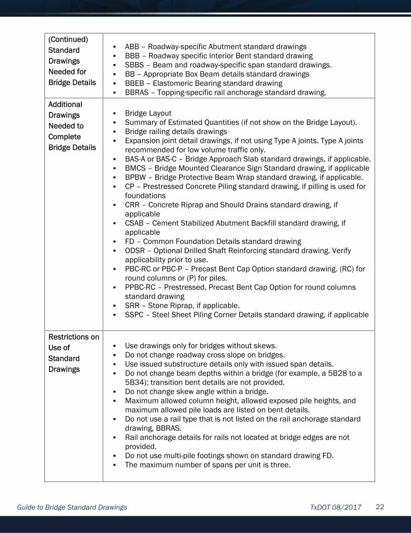
(Continued) Standard Drawings Needed for Bridge Details
ABB – Roadway-specific Abutment standard drawings BBB – Roadway specific Interior Bent standard drawing SBBS – Beam and roadway-specific span standard drawings. BB – Appropriate Box Beam details standard drawings BBEB – Elastomeric Bearing standard drawing BBRAS – Topping-specific rail anchorage standard drawing.
Additional Drawings Needed to Complete Bridge Details
Bridge Layout Summary of Estimated Quantities (if not show on the Bridge Layout). Bridge railing details drawings Expansion joint detail drawings, if not using Type A joints. Type A joints
recommended for low volume traffic only. BAS-A or BAS-C – Bridge Approach Slab standard drawings, if applicable. BMCS – Bridge Mounted Clearance Sign Standard drawing, if applicable BPBW – Bridge Protective Beam Wrap standard drawing, if applicable. CP – Prestressed Concrete Piling standard drawing, if pilling is used for
foundations CRR – Concrete Riprap and Should Drains standard drawing, if
applicable CSAB – Cement Stabilized Abutment Backfill standard drawing, if
applicable FD – Common Foundation Details standard drawing ODSR – Optional Drilled Shaft Reinforcing standard drawing. Verify
applicability prior to use. PBC-RC or PBC-P – Precast Bent Cap Option standard drawing. (RC) for
round columns or (P) for piles. PPBC-RC – Prestressed, Precast Bent Cap Option for round columns
standard drawing SRR – Stone Riprap, if applicable. SSPC – Steel Sheet Piling Corner Details standard drawing, if applicable
Restrictions on Use of Standard Drawings
Use drawings only for bridges without skews. Do not change roadway cross slope on bridges. Use issued substructure details only with issued span details. Do not change beam depths within a bridge (for example, a 5B28 to a
5B34); transition bent details are not provided. Do not change skew angle within a bridge. Maximum allowed column height, allowed exposed pile heights, and
maximum allowed pile loads are listed on bent details. Do not use a rail type that is not listed on the rail anchorage standard
drawing, BBRAS. Rail anchorage details for rails not located at bridge edges are not
provided. Do not use multi-pile footings shown on standard drawing FD. The maximum number of spans per unit is three.

Guide to Bridge Standard Drawings TxDOT 08/2017 23
(Continued) Restrictions on Use of Standard Drawings
Some unit lengths are too great to use sealed or open armor joints and
Type A joints. Drawings do not accommodate raised sidewalks and medians or rails
not on edge of slab. If adding a raised sidewalk, median or rail, check standard drawing for additional loading.
Do not use rail types T66, T80HT, T80SS, C412, C66, T221P, or T224. Their width or weight precludes their use on standard roadway width spans.
Do not use single-sided crash cushions (see Design Division standard drawing SSCC-03A) with abutment wingwall lengths less than 7 ft.
NOTE: Some restrictions may be overcome by modifying the standard drawings with appropriate additional details and information. Denote modified details as MOD in the title block, and clearly indicate which details were modified in the standard drawing sheet. All modified standard drawings must be signed, sealed, and dated by a registered Professional Engineer.
Special Considerations
Quantities provided for reinforcing steel weight are not bid items. They
are provided for Contractor’s information only. If roadway vertical curve is used, adjust section depths listed on span
details. Section depth adjustment does not justify standard drawing modification.
Bearing seats are not used on box beam bridges; the pads sit directly on the top of the cap. Top of cap elevations must be provided at the points coinciding with the outer edge of exterior boxes at centerline of bearing and at all intermediate points where a change in cap slope occurs.
Spreadsheet STD-BRG.xls, available from the Bridge Division, is a tool to help calculate and generate top of cap elevations and bearing pad tapers.
Adjust bent concrete quantities as needed for column heights shown on the Bridge Layout. Adjust abutment concrete quantities if not using approach slabs. See substructure standard drawings for guidance.
Earwalls are incorporated into abutments and interior bents for lateral restraint of the superstructure: exterior beams bear against the earwalls with a ½-inch layer of preformed bituminous fiber material between beam and earwall. It may be difficult to ensure that beams fit within the earwalls or bear against them due to fabrication and construction tolerances and lateral translation of beams on neoprene bearings resulting from roadway cross-slope. Therefore, substructure details require earwalls be cast after beams are set, using the beams as a form.
The Prestessed, Precast Bent Cap Option for round columns (PPBC-RC) standard drawing does not provide details for ear walls. See the bent details for earwall details.

Guide to Bridge Standard Drawings TxDOT 08/2017 24
(Continued) Special Considerations
To limit negative effects of pad lateral deflection due to beam dead
load, erect first the beams adjacent to crown point or at high side of single cross slope.
Beam ends located at expansion joints (other than Type A joints) must have a blockout to provide room for expansion joint anchors. See standard drawings with a BB prefix for blockout details.
When widening existing structures, like topping is recommended. T631 and T631LS cast-in-place anchorage details provided on standard
drawing BBRAS are based on the maximum “X” dimension (slab thickness at CL of bearing) of 10 in. If slab thickness exceeds 10 in. at any point along the beam, modify length of anchor bolt accordingly.
Do not use open bridge rails—such as T223, T552, etc.—when frequent use of de-icing agents is anticipated.
Specific Bridge Layout Requirements
List unit lengths if not locating expansion joints at each bent. See span
details for limits on unit length. Verify that column or exposed pile heights do not exceed values listed
on bent standard drawings. These maximum heights must be evaluated by the Engineer in areas of soft soil or where scour is anticipated.
Recommended expansion joints in order of preference are 4-in. sealed expansion joints (see standard drawing SEJ-A), sealed armor joints (see standard drawing AJ), and Type A joints (see standard box beam span drawings SBBS). Type A joints and open armor joints are recommended for low volume roads only. Do not place Type A joints more than 100 ft. apart for proper joint performance.
Note roadway width as nominal in Plan view and Typical Section for 24-, 28-, and 30-ft. roadway structures. Overall width in Plan view and Typical Section must be shown as actual overall width – for example, 32.334 ft. for 30-ft. roadway structures.

Guide to Bridge Standard Drawings TxDOT 08/2017 25
Pretensioned Concrete Spread Box Beams (X-Beams) Bridge Standard Drawings
Advantages/ Usefulness
Pretensioned concrete X-beams are useful for bridges requiring shallow
superstructures and where future widening is anticipated. Pretensioned concrete X-beam bridges are predicted to cost more than
pretensioned concrete I-Girder bridges but less than conventional pretensioned concrete box beam bridges.
Construction is similar to pretensioned concrete I-Girder bridges.
Standard Drawing Location
XB prefixes. Web site:
http://www.dot.state.tx.us/insdtdot/orgchart/cmd/cserve/standard/bridge-e.htm#XBeams
Standard Drawing Features
Designed for HL93 live load in accordance with AASHTO LRFD Bridge
Design Specifications. Drawings Accommodate:
Four beam depths (20-, 28-, 34-, and 40-in.), each in two nominal widths (4-ft. and 5-ft.). Only 5-ft. wide beams are used with the standard roadway widths.
32-, 38-, 40-, and 44-ft. roadway widths 0-, 15-, and 30-degree skew angles. Span lengths of 40-ft. through 110-ft., in 5-ft. increments. Not all beam
types accommodate all span lengths. Abutment header slopes of 2:1 and 3:1. Most standard rail types.
Roadway surface is a cast-in-place concrete slab with 8-inch depth. Details are provided to construct 2- or 3-span units with slabs continuous
over interior bents. Using units reduces the number of expansion joints. Drawings support these foundation options:
Drilled shafts (36-in) Multi-pile footings Prestressed concrete piling (16-, 18-, 20-,24-in) Steel H-piling (14x73, 14x117, 18x135)
Nine standard drawings are provided to use with customized bridge plans.
Standard Drawings Needed for Bridge Details
XBSD – Roadway-specific Prestressed Concrete X-Beam Standard Design
standard drawing

Guide to Bridge Standard Drawings TxDOT 08/2017 26
(Continued) Standard Drawings Needed for Bridge Details
AXB – Roadway and skew-specific Abutment standard drawing BXB or BTXB – Roadway and skew-specific Interior Bent standard drawing
or for interior Trestle Bents SXB – Roadway and skew-specific span standard drawing Beam depth-specific Prestressed Concrete X-Beam Details standard
drawing (XB20, XB28, XB34, or XB40). XBBR-MS – Minimum Erection Bracing Requirements with Miscellaneous
Slab Details standard drawing. XBCS – Continuous Slab details standard drawing. (Only if using multi-
span unit with slab continuous over interior bents). XBEB – Elastomeric Bearing standard drawing XBTS – Thickened Slab End Details standard drawing
Additional Drawings Needed to Complete Bridge Details
Bridge Layout Summary of Estimated Quantities (if not shown on Bridge layout). Drawing with bearing seat elevations. (Recommended, see “Special
Considerations”). Expansion joint detail drawings Bridge railing detail drawings BAS-A or BAS-C – Bridge Approach Slab Standard drawing, if applicable. BMCS – Bridge Mounted Clearance Sign standard drawing, if applicable. BL – Bridge Lighting standard drawing, if applicable. BPBW – Bridge Protective Beam Wrap, if applicable. CP – Prestressed Concrete Piling standard, if piling is used for
foundations. CRR – Concrete Riprap and Shoulder Drain standard drawing, if
applicable CSAB – Cement Stabilized Abutment Backfill standard drawing, if
applicable. FD – Common Foundation Details standard drawing ODSR – Optional Drilled Shaft Reinforcing standard drawing. Verify
applicability prior to use. PBC-RC or PBC-P – Precast Bent Cap Option standard drawing. Use (RC)
for round columns and (P) for piles. PCP and PCP-FAB – Prestressed Concrete Panel standard drawings PMDF – Permanent Metal Deck Form standard drawing PPBC-RC – Prestressed, Precast Bent Cap Option for round columns
standard drawing SRR – Stone Riprap, if applicable. XBSK - X-Beam Shear Key standard drawing, if applicable SSPC – Steel Sheet Piling Corner Details standard drawing, if applicable
Restrictions on Use of Standard Drawings
Do not change roadway cross slope on bridges and do not allow roadway
vertical curves on bridges with skewed supports. These two restrictions are to simplify calculations for bearing seat elevations.

Guide to Bridge Standard Drawings TxDOT 08/2017 27
(Continued) Restrictions on Use of Standard Drawings
Skew angle is limited to 30 degrees. Do not change beam type (for example, Type 5XB20 to 5XB34) within a
bridge; transition bent details are not provided. Maximum allowed column height, allowed exposed pile heights, and
maximum allowed pile loads are listed on bent details. Do not use rail types T66, T80HT, T80SS, C412, C66, or T224. Their
width or weight precludes their use on standard roadway width spans. Use issued substructure details only with issued span details. The maximum number of spans per unit is three. The maximum unit
length cannot exceed the limits shown on standard drawing XBCS. Some unit lengths are too great to use sealed or open armor joints and
Type A joints. Do not change skew angle within a bridge. Do not use single-sided crash cushions (see Design Division standard
drawing SSCC-03A) with abutment wingwall lengths less than 7 ft. Drawings do not accommodate raised sidewalks and medians or rails not
on edge of slab. If adding a raised sidewalk, median or rail, check standard drawing for additional loading.
Note: Some restrictions may be overcome by modifying the standard drawings with appropriate additional details and information. Denote modified details as MOD in the title block, and clearly indicate which details were modified in the standard drawing sheet. All modified standard drawings must be signed, sealed, and dated by a registered Professional Engineer.
Special Considerations
Provide bearing seat elevations in the plans. The bearing seats are
sloped with the roadway cross-slope along the bent, not level, and two elevations—left side and right side—need to be provided for each bearing seat. If an adjustment is made to the section depth (to accommodate a sag vertical curve, for example), it is recommended to note the section depth adjustment used along with the bearing seat elevations.
Spreadsheet STD-BRG.xls, available from the Bridge Division, is a tool to help calculate and generate bearing seat elevations and bearing pad tapers.
If the presence of a roadway vertical curve forces a haunch depth greater than 3.5-in at any point on a beam, standard drawing XBBR-MS instructs the contractor to reinforce the haunch. If prestressed concrete panels are used as a forming option, this haunch reinforcement is shown on standard drawing PCP.
Do not use open bridge rails--such as T223, T552, etc.—when frequent use of de-icing agents is anticipated. If deck drainage is desired and de-icing agent use is predicted, use the drain details shown on standard drawing XBBR-MS. Locate the drain locations on the Bridge Layout (no closer than 4 ft. from centerline of substructure caps).

Guide to Bridge Standard Drawings TxDOT 08/2017 28
(Continued) Special Considerations
Adjust bent concrete quantities as needed for column heights shown on
the Bridge Layout. Adjust abutment concrete quantities if not using approach slabs. See substructure standard drawings for guidance.
On substructure standard drawings, dowel bars D are noted to be excluded at ends of units. Therefore, if continuous slab units are indicated on the Bridge Layout and standard drawing XBCS is included in the plans, do not use dowels at unit ends (expansion joint locations).
Quantities provided for reinforcing steel weight and slab concrete volume are not bid items. They are provided for Contractor’s information only.
The Prestressed, Precast Bent Cap Option for round columns (PPBC-RC) standard drawing only provides pedestal details for non-skewed bents and pedestals up to 18 inches tall. Provide details for pedestals on skewed bents. In addition, if shear keys are required, provide shear key details considering strand location, column location, and shear key reinforcement.
Specific Bridge Layout Requirements
Label all beam ends with a “D”, except when using multi-span units. With
units, do not label beam ends “D” at expansion joint locations. List unit lengths, if not locating expansion joints at each bent. For
continuous slabs, see details and notes on span standard drawings and standard XBCS; two- or three-span units are conditionally permitted.
Verify that column heights do not exceed values listed on bent standard drawings. These maximum heights must be evaluated by the Engineer in areas of soft soil or where scour is anticipated.
Indicate abutment wingwall foundations, if required. See Abutment standard drawings for wingwall foundation requirements, based on beam type and header slope.
Recommended expansion joints in order of preference are 4-in. sealed expansion joints (see standard drawing SEJ-A) and sealed armor joints (see standard drawing AJ), and Type A joints (see standard drawing XBBR-MS). Type A joints and open armor joints are not recommended for On-System structures. Type A joints are recommended for bridges with low traffic volumes only. Do not place Type A joints more than 100 ft. apart for proper joint performance.
Guide to Bridge Standard Drawings TxDOT 08/2017 29
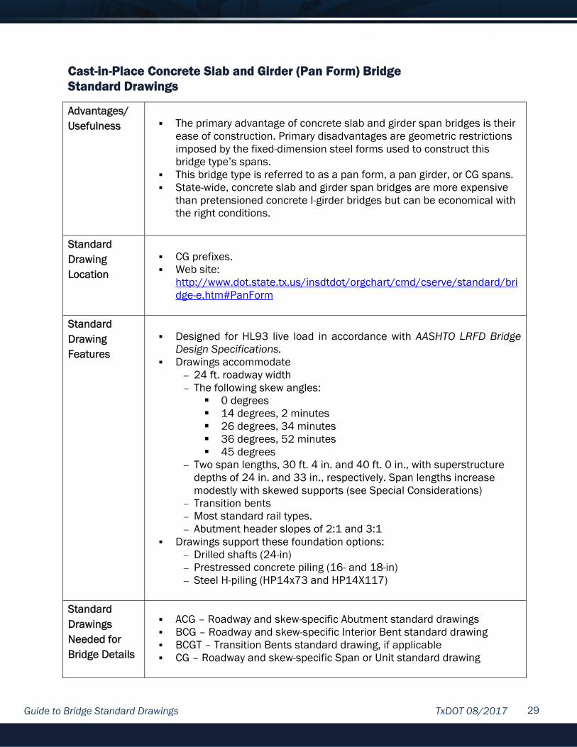
Cast-in-Place Concrete Slab and Girder (Pan Form) Bridge Standard Drawings
Advantages/ Usefulness
The primary advantage of concrete slab and girder span bridges is their
ease of construction. Primary disadvantages are geometric restrictions imposed by the fixed-dimension steel forms used to construct this bridge type’s spans.
This bridge type is referred to as a pan form, a pan girder, or CG spans. State-wide, concrete slab and girder span bridges are more expensive
than pretensioned concrete I-girder bridges but can be economical with the right conditions.
Standard Drawing Location
CG prefixes. Web site:
http://www.dot.state.tx.us/insdtdot/orgchart/cmd/cserve/standard/bridge-e.htm#PanForm
Standard Drawing Features
Designed for HL93 live load in accordance with AASHTO LRFD Bridge
Design Specifications. Drawings accommodate
24 ft. roadway width The following skew angles:
0 degrees 14 degrees, 2 minutes 26 degrees, 34 minutes 36 degrees, 52 minutes 45 degrees
Two span lengths, 30 ft. 4 in. and 40 ft. 0 in., with superstructure depths of 24 in. and 33 in., respectively. Span lengths increase modestly with skewed supports (see Special Considerations)
Transition bents Most standard rail types. Abutment header slopes of 2:1 and 3:1
Drawings support these foundation options: Drilled shafts (24-in) Prestressed concrete piling (16- and 18-in) Steel H-piling (HP14x73 and HP14X117)
Standard Drawings Needed for Bridge Details
ACG – Roadway and skew-specific Abutment standard drawings BCG – Roadway and skew-specific Interior Bent standard drawing BCGT – Transition Bents standard drawing, if applicable CG – Roadway and skew-specific Span or Unit standard drawing

Guide to Bridge Standard Drawings TxDOT 08/2017 30
(Continued) Standard Drawings Needed for Bridge Details
CG-MD – Miscellaneous Details for Concrete Slab and Girder Spans
standard CGRAD – Rail Anchorage Details for Concrete Slab and Girder Spans
standard drawing
Additional Drawings Needed to Complete Bridge Details
Bridge Layout Summary of Estimated Quantities (if not shown on Bridge Layout). Bridge railing detail drawings. Expansion Joint detail drawings. BAS-A or BAS-C – Bridge Approach Slab standard drawing, if applicable. CP – Prestressed Concrete Piling Standard drawing, if piling is the
foundation type. CRR – Concrete Riprap and Shoulder Drains standard drawing, if
applicable. CSAB – Cement Stabilized Abutment Backfill standard drawing, if
applicable FD – Common Foundation Details standard drawing ODSR – Optional Drilled Shaft Reinforcing standard drawing. Verify
applicability prior to use. SRR – Stone Riprap, if applicable. SSPC – Steel Sheet Piling Corner Details standard drawing, if applicable
Restrictions on Use of Standard Drawings
Do not change standard span lengths without changing bent cap width.
The two standard span lengths are based on the span’s fixed length steel forms fitting between 24-in. wide substructure caps.
The only skews available are those listed on the span standard drawings. This constraint is due to steel form assembly restrictions.
Do not change skew angle within a bridge. Maximum allowed slab overhang is 13.75 in. Maximum allowed column height, allowed exposed pile heights, and
maximum allowed pile loads are listed on bent details. . Do not use a rail type that is not listed on the CGRAD standard drawing. Do not use multi-pile footings shown on standard drawing FD. Use issued substructure details only with issued span details. Do not use single-sided crash cushions (see Design Division standard
drawing SSCC-03A) with abutment wingwall lengths less than 7 ft. Do not use rail types T66, T80HT, T80SS, C412, C66, or T224. Their
width or weight precludes their use on standard roadway width spans. Drawings do not accommodate raised sidewalks and medians or rails
not on edge of slab. If adding a raised sidewalk, median or rail, check standard drawing for additional loading.
NOTE: Some restrictions may be overcome by modifying the standard drawings with appropriate additional details and information. Denote modified details as MOD in the title block, and clearly indicate which details were modified in the standard drawing sheet. All modified standard drawings must be signed, sealed, and dated by a registered Professional Engineer.

Guide to Bridge Standard Drawings TxDOT 08/2017 31
Special Considerations
Adjust bent concrete quantities as needed for column heights shown on
the Bridge Layout and for transition bents. Adjust abutment concrete quantities if not using approach slabs. See substructure standard drawings for guidance.
Spreadsheet STD-BRG.xls, available from the Bridge Division, is a tool to help calculate and generate top of cap elevations.
Slab concrete is paid by the cubic yard of Concrete Pan Girder. Actual lengths of spans on skewed supports are longer than nominal
span lengths (30 ft. 4 in. and 40 ft. 0 in.) because of steel form assembly requirements. Bent stations and span lengths shown on bridge layouts should reflect actual span lengths, which can be found for each skew on the span standard drawings.
Standard drawing CG-MD provides guidance and restrictions on locating expansion joint locations on the bridge layout.
4-in. x 3/8-in. expansion joint material placed on the top corners of all substructure caps (see standard drawing CG-MD for details) prevents spalling of cap concrete due to span rotation, deflection, and expansion.
Never use dowels Q, shown on standard drawing CG-MD, on both sides of a cap at fixed bent locations.
Windows in the bottom of span end diaphragms are required at all expansion joint locations (see standard drawing CG-MD) to help water and debris exit between span ends. Sealed expansion joints (see standard drawing SEJ-A) and sealed armor joints (see standard drawing AJ) are recommended with this structure type.
If 18-in prestressed concrete piling is used, the piling will probably need to be broken back to fit in substructure caps. See piling standard drawing for break-back details.
Do not use open bridge rails—such as T223, T552, etc.—when frequent use of de-icing agents is anticipated.
Specific Bridge Layout Requirements
In the Elevation view, indicate support condition at each bent—for
example, “E” or “F”. See standard drawing CG-MD for more information. In the Plan view, indicate expansion joint type at each bent that is
labelled “E” in Elevation. Verify that column or exposed pile heights do not exceed values listed
on bent standard drawings. These maximum heights must be evaluated by the Engineer in areas of soft soil or where scour is anticipated.

Guide to Bridge Standard Drawings TxDOT 08/2017 32
Cast-in-Place Concrete Slab Span Bridge Standard Drawings
Advantages/ Usefulness
Cast-in-place concrete slab span bridges have shallower
superstructures than any other bridge for which TxDOT standard drawings exist.
Cast-in-place concrete slab span bridges have short span lengths. Cast-in-place concrete slab span bridges have comparable cost to
concrete slab and girder (pan form) bridges.
Standard Drawing Location
CS prefixes. Web site:
http://www.dot.state.tx.us/insdtdot/orgchart/cmd/cserve/standard/bridge-e.htm#SlabSpans
Standard Drawing Features
Designed for HL93 live load in accordance with AASHTO LRFD Bridge
Design Specifications. Drawings accommodate
24-, 28-, 30-, 38-, and 44-ft. roadway widths. 0-, 15-, and 30-degree skew angles Drawings provide a 14-in slab depth with a two-span (each 25ft) unit
and with three-span (each 25 ft.) unit. Drawings provide a 16-in.slab depth with a simple span (25ft) and
with a three-span (25 ft., 30ft., and 25 ft.) unit. Abutment header slopes of 2:1 and 3:1 Most standard rail types.
Drawings support these foundation options: Drilled shafts (24-in) Prestressed concrete piling (16-and 18-in.) Steel H-piling (HP14x73 and HP14x117)
Standard Drawings Needed for Bridge Details
ACS – Roadway and skew-specific Abutment standard drawing. Some
skewed abutment standard drawings are foundation-specific (for example, for drilled shafts and pilings).
BCS - Roadway and skew-specific Interior Bent standard drawing CS – Roadway and skew-specific Span or Unit standard drawing CS-MD – Miscellaneous Details for Cast-in-Place Concrete Slab Span
standard drawing. Additional Drawings Needed to Complete Bridge Details (Continued)
Bridge Layout. Summary of Estimated Quantities (if not shown on the Bridge Layout). Bridge railing detail drawings BAS-A or BAS-C – Bridge Approach Slab standard drawing, if applicable

Guide to Bridge Standard Drawings TxDOT 08/2017 33
Additional Drawings Needed to Complete Bridge Details
CP - Prestressed Concrete Piling standard drawing if pilling is the
foundation type. CRR - Concrete Riprap and Shoulder Drains standard drawing, if
applicable. CSAB – Cement Stabilized Abutment Backfill standard drawing, if
applicable. FD – Common Foundation Details standard drawing ODSR – Optional Drilled Shaft Reinforcing standard drawing. Verify
applicability prior to use. SRR – Stone Riprap, if applicable. SSPC – Steel Sheet Piling Corner Details standard drawing, if applicable.
Restrictions on Use of Standard Drawings
Do not change slab depth (for example, 14-in. to 16 in) within bridges;
transition bent details are not provided. Skew angle is limited to 30 degrees. Do not change skew angle within a bridge. Maximum allowed column height, allowed exposed pile heights, and
maximum allowed pile loads are listed on bent details. Do not use rail types T66, T80HT, T80SS, C412, C66, or T224. Their
width or weight precludes their use on standard roadway width spans. Do not use multi-pile footings shown on standard drawing FD. Use issued substructure standard drawings only with issued span
standard drawings. Do not use open armor joints; no mechanism for draining silt and other
debris from joints and substructure caps exists with armor joints or any other open joint.
Do not use single-sided cushions (see Design Division standard drawing SSCC-03A) with abutment wingwall lengths less than 7 ft.
Drawings do not accommodate raised sidewalks and medians or rails not on edge of slab. If adding a raised sidewalk, median or rail, check standard drawing for additional loading.
NOTE: Some restrictions may be overcome by modifying the standard drawings with appropriate additional details and information. Denote modified details as MOD in the title block, and clearly indicate which details were modified in the standard drawing sheet. All modified standard drawings must be signed, sealed, and dated by a registered Professional Engineer.
Special Considerations
Use 16-in. deep slab span details for only a one-span bridge or a bridge
needing a 30-ft. span as part of a three-span (25-ft., 30-ft., and 25-ft.) unit. Otherwise, the drawings accommodate any number of spans greater than one with span details for a 14-in. deep slab.

Guide to Bridge Standard Drawings TxDOT 08/2017 34
(Continued) Special Considerations
Adjust bent concrete quantities as needed for column heights shown on
the Bridge Layout. Adjust abutment concrete quantities if not using approach slabs. See substructure standard drawings for guidance.
Slab concrete is paid by the cubic yard of Class S Concrete (Slab). Actual span lengths for spans on supports skewed 30 degrees are 0.5
ft. longer than nominal span length. This allows the same length bar joist to support slab formwork regardless of skew. Bent stations and span lengths shown on bridge layouts should reflect actual span lengths.
Spreadsheet STD-BRG.xls, available from the Bridge Division, is a tool to help calculate and generate top of cap elevations.
Skewed substructure caps are deeper than non-skewed caps to accommodate shear keys formed into the tops of skewed caps.
A bent with a FIX expansion condition may support two simple spans. Standard drawing CS-MD provides guidance and quantity adjustments for use of this condition. Only one of these spans may be anchored to the bent with Dowels Q (shown on this standard drawing and bent standard drawings) to prevent spalling of cap concrete.
To prevent spalling of cap concrete due to span rotation, deflection, and expansion, 4-in. by 1/4-in. preformed bituminous fiber material is placed on the top corners of all substructure caps. See standard drawing CS-MD for details.
Standard drawing CS-MD provides a detail allowing approach slabs to be cast to the top of abutment caps.
Type A expansion joints are the only expansion joints supported for these standard drawings. The small thermal movements expected from cast-in-place slab construction do not justify the cost of using strip seal expansion joints (see standard drawing SEJ-A). Type A expansion joints, detailed on span standard drawings, are not paid for directly but are considered subsidiary to Item 422, “Concrete Superstructures.”
Do not use open bridge rails—such as T223, T552 , etc.—when frequent use of de-icing agents is anticipated
Specific Bridge Layout Requirements
In the Elevation view, indicate fixity at each bent (EXP or FIX). Use
standard drawing CS-MD for assistance. In the Plan view, indicate Type A expansion joint at each bent labelled
EXP in the Elevation view. Verify that column or exposed pile heights do not exceed values listed
on bent standard drawings. These maximum heights must be evaluated by the Engineer in areas of soft soil or where scour is anticipated.

Guide to Bridge Standard Drawings TxDOT 08/2017 35
Steel Beam Bridge Standard Drawings
Advantages/ Usefulness
Steel beams are useful for bridges requiring shallow superstructures,
bridges where future widening is anticipated, and bridges where crane weight, capacity, and location are issues.
Steel beam bridges are cost comparable to pretensioned concrete box beam bridges.
Construction is similar to pretensioned concrete I-Girder bridge construction.
Standard Drawing Location
SB prefixes. Web site:
http://www.dot.state.tx.us/insdtdot/orgchart/cmd/cserve/standard/bridge-e.htm#SteelBeams
Standard Drawing Features
Designed for HL93 live load in accordance with AASHTO LRFD Bridge
Design Specifications. Drawings accommodate
24-, 28-, and 30-ft. roadway widths. 0-, 15-, and 30-degree skew angles. Eight rolled beam types (W18, W21, W24, W27, W30, W33, W36,
and W40). Optional plate girders for each rolled beam Weathering and painted steel Span lengths of 30 ft. through 120 ft., in 5 ft. increments. Not all
beam types accommodate all span lengths. Abutment header slopes of 2:1 and 3:1. Most standard rail types.
Roadway surface is a cast-in-place concrete slab with 8-in. depth. Details are provided to construct 2- or 3-span units with slabs
continuous over interior bents. Using units reduces the number of expansion joints.
Drawings support these foundation options: Drilled shafts (30-in) Prestressed concrete piling (16-, 18-, and 20-in.) Steel H-piling (HP14x73 and HP14x117). Pile bents are not available for all span and roadway combinations.
Standard drawings are not provided for use with customized bridge plans.
Standard Drawings Needed for Bridge Details
SBSD – Roadway specific Steel Beam Standard Design standard
drawing. ASB – Roadway and skew-specific Abutment standard drawing. BSB – Roadway and skew specific Interior Bent standard drawing.

Guide to Bridge Standard Drawings TxDOT 08/2017 36
(Continued) Standard Drawings Needed for Bridge Details
SSB – Roadway and skew specific span standard drawing. SBBR – Standard Erection and Bracing Requirements standard drawing. SBCS – Slab details standard drawing. Continuous Slab details standard
drawing SBCS (only if using multi-span units with slab continuous over interior bents).
SBEB – Elastomeric Bearing standard drawing. SBMD – Steel Beam Miscellaneous Details standard drawing. SBMS – Steel Beam Miscellaneous Slab Details standard drawing. SBTS – Steel Beam Thickened Slab End Details standard drawing.
Additional Drawings Needed to Complete Bridge Details
Bridge Layout Summary of Estimated Quantities (if not shown on Bridge Layout). Drawing with bearing seat elevations (Recommended, see “Special
Considerations”). Bridge railing detail drawings. Expansion joint detail drawings. General notes that specify whether the steel is to be painted. BAS-A or BAS-C – Bridge Approach Slab standard drawing, if applicable. BL – Bridge Lightning standard drawing, if applicable. BMCS – Bridge Mounted Clearance Sign standard drawing, if applicable CP –Prestressed Concrete Piling standard drawing. CRR – Concrete Riprap and Shoulder Drain standard drawing, if
applicable. CSAB – Cement Stabilized Abutment Backfill standard drawing, if
applicable. FD – Common Foundation Details ODSR – Optional Drilled Shaft Reinforcing standard drawing. Verify
applicability prior to use. PBC-RC or PBC-P – Precast Bent Cap Option standard drawing. (RC) for
round columns or (P) for piles. PCP &PCP-FAB – Prestressed Concrete Panel standard drawings PMDF – Permanent Metal Deck Form standard drawing SRR – Stone Riprap, if applicable. SSPC – Steel Sheet Piling Corner Details standard drawing, if applicable.
Restrictions on Use of Standard Drawings
Do not change beam type (such as W18 to W21) within a bridge;
transition bent details are not provided. Do not change skew angle within a bridge. Maximum allowed column height, allowed exposed pile heights, and
maximum allowed pile loads are listed on bent details. . Do not use rail types T66, T80HT, T80SS, C412, C66, or T224. Their
width or weight precludes their use on standard roadway width spans. Do not use multi-pile footings shown on standard drawing FD. Use issued substructure details only with issued span details.

Guide to Bridge Standard Drawings TxDOT 08/2017 37
(Continued) Restrictions on Use of Standard Drawings
The maximum number of spans per unit is three, and maximum unit
length must not exceed three times the length of the shortest end span. For example, a two-span unit with span lengths of 30 ft. and 60 ft. is acceptable, but a two-span unit with span lengths of 50 ft. and 115 ft. is not.
Do not use single-sided crash cushions (see Design Division standard drawing SSCC-03A) with abutment wingwall lengths less than 7 ft.
Drawings do not accommodate raised sidewalks and medians or rails not on edge of slab. If adding a raised sidewalk, median or rail, check standard drawing for additional loading.
NOTE: Some restrictions may be overcome by modifying the standard drawings with appropriate additional details and information. Denote modified details as MOD in the title block, and clearly indicate which details were modified in the standard drawing sheet. All modified standard drawings must be signed, sealed, and dated by a registered Professional Engineer.
Special Considerations
When selecting a beam type for a bridge, find the bridge’s maximum
span length on the roadway-specific SBSD standard drawing, which lists beam types along with their weight per linear foot; for example, W18x130 is a W18 beam with a weight of 130 plf. In most cases, multiple beam types are available for a given span length. If vertical clearance or hydraulic demands are not an issue, prepare the layout with the lightest beam type instead of the beam with least section depth to minimize bridge cost. Consider the whole bridge when comparing steel weights.
Specify unpainted weathering steel in the plan’s general notes for the least cost structure. However, avoid weathering steel if any of the following conditions exist: low steel is less than 8 ft. above normal water elevation, open armor joints are used, frequent use of de-icing agents is anticipated, or staining of riprap at embankments would be objectionable.
Do not use open bridge rails—such as T223 and T552—when frequent use of de-icing agents is anticipated. If deck drainage is desired and de-icing agents use is predicted, use the drain details shown on standard drawing SBMS. Locate these drains on the Bridge Layout (no closer than 4 ft. from centerline of substructure caps).
Refer to the Table of Maximum Allowable Exposed Pile Heights and Pile Loads and the Table of Foundation Loads on the Interior Bents standard drawing when sizing piles for the Bridge Layout. Some roadway/span combinations cannot use pile bents.
All beams and optional plate girders are specified to be cambered for total dead load deflection. Optional plate girders are specified to have additional camber for any crest roadway vertical curve. If a sag roadway vertical curve is located on the span, the top-of-slab to top-of-beam
Guide to Bridge Standard Drawings TxDOT 08/2017 38
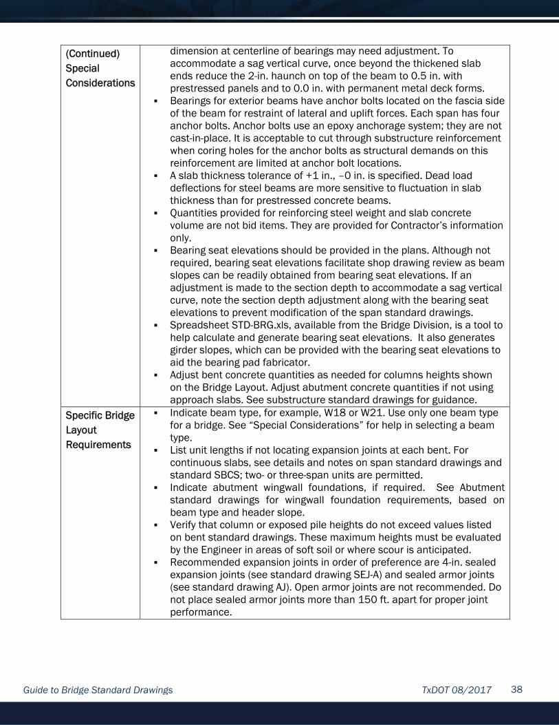
(Continued) Special Considerations
dimension at centerline of bearings may need adjustment. To accommodate a sag vertical curve, once beyond the thickened slab ends reduce the 2-in. haunch on top of the beam to 0.5 in. with prestressed panels and to 0.0 in. with permanent metal deck forms.
Bearings for exterior beams have anchor bolts located on the fascia side of the beam for restraint of lateral and uplift forces. Each span has four anchor bolts. Anchor bolts use an epoxy anchorage system; they are not cast-in-place. It is acceptable to cut through substructure reinforcement when coring holes for the anchor bolts as structural demands on this reinforcement are limited at anchor bolt locations.
A slab thickness tolerance of +1 in., –0 in. is specified. Dead load deflections for steel beams are more sensitive to fluctuation in slab thickness than for prestressed concrete beams.
Quantities provided for reinforcing steel weight and slab concrete volume are not bid items. They are provided for Contractor’s information only.
Bearing seat elevations should be provided in the plans. Although not required, bearing seat elevations facilitate shop drawing review as beam slopes can be readily obtained from bearing seat elevations. If an adjustment is made to the section depth to accommodate a sag vertical curve, note the section depth adjustment along with the bearing seat elevations to prevent modification of the span standard drawings.
Spreadsheet STD-BRG.xls, available from the Bridge Division, is a tool to help calculate and generate bearing seat elevations. It also generates girder slopes, which can be provided with the bearing seat elevations to aid the bearing pad fabricator.
Adjust bent concrete quantities as needed for columns heights shown on the Bridge Layout. Adjust abutment concrete quantities if not using approach slabs. See substructure standard drawings for guidance.
Specific Bridge Layout Requirements
Indicate beam type, for example, W18 or W21. Use only one beam type for a bridge. See “Special Considerations” for help in selecting a beam type.
List unit lengths if not locating expansion joints at each bent. For continuous slabs, see details and notes on span standard drawings and standard SBCS; two- or three-span units are permitted.
Indicate abutment wingwall foundations, if required. See Abutment standard drawings for wingwall foundation requirements, based on beam type and header slope.
Verify that column or exposed pile heights do not exceed values listed on bent standard drawings. These maximum heights must be evaluated by the Engineer in areas of soft soil or where scour is anticipated.
Recommended expansion joints in order of preference are 4-in. sealed expansion joints (see standard drawing SEJ-A) and sealed armor joints (see standard drawing AJ). Open armor joints are not recommended. Do not place sealed armor joints more than 150 ft. apart for proper joint performance.