Embed Size (px)
Citation preview

GUIDE TO BETTER BUILDING
ENVELOPES FOR
LARGE BUILDINGS — 2016

This Guide was developed in partnership with:
This Guide is intended to provide general information on building envelope design and construction best practices. This
Guide is not a replacement for knowledge of construction techniques, building science and relevant building codes and it
is not intended to provide construction or design advice. We cannot guarantee that all information is current or accurate.
Users should verify the information before acting on it. References in this Guide to other sources of information are
presented as a convenience to users. The Government of Newfoundland and Labrador, does not accept any responsibility
for the content, accuracy, reliability, or currency of information contained in this Guide or in sources of information
referenced by it. Information in this Guide is provided solely for the user’s information and it is provided without warranty,
guarantee, or responsibility of any kind, either express or implied. The Government of Newfoundland and Labrador and
its employees will not be liable for any loss or damages of any nature, either direct or indirect, arising from use of the
information provided in this Guide.
DISCLAIMER:

Preface
Purpose of this Guide ...................................................................................................................... 4
Section 1 — Introduction
The Building Envelope .................................................................................................................... 7
Influences on Building Envelope Design and Construction .............................................. 7
Leadership in Energy and Environmental Design (LEED) .................................... 8
ASHRAE Standard 90.1 ...................................................................................................... 9
The National Energy Code of Canada for Buildings (NECB) .............................. 9
Pushing the Envelope .................................................................................................................... 10
Section 2 — Building Envelope Best Practices
Beyond Codes, Rating Systems and Standards ...................................................................13
Achieving Higher Effective Insulation Values........................................................................13
Effective vs. Nominal Insulation Values ......................................................................13
Reducing Thermal Bridging .........................................................................................................15
Appropriate Glazing Ratios and Improved Glazing Performance .................................15
Specifying and Verifying Functional Performance ............................................................. 17
Section 3 — Higher Performance Building Envelopes in Practice
Minimizing Thermal Bridging and Increasing Effective Insulation Values ................20
NECB 2011 Prescriptive Requirements .......................................................................20
Achieving Higher Performance Building Assemblies ...........................................22
Canadian Wood Council Thermal Wall Design Calculator .................................24
ASHRAE 90.1 Tables ..........................................................................................................25
COMcheck .............................................................................................................................25
Building Envelope Thermal Bridging Guide .............................................................26
Appropriate Glazing Ratios .........................................................................................................28
Specifying and Verifying Functional Performance ............................................................29
A Review ..............................................................................................................................................31
Appendices
Appendix A – Municipalities by Climate Zone .....................................................................33
Appendix B – Further Resources ..............................................................................................36
Appendix C – Glossary of Terms ...............................................................................................38
TABLE OF CONTENTS

4
PREFACE SECTION 1: Introduction SECTION 2: Best Practices SECTION 3: In Practice APPENDICES
This Guide is intended to provide an overview of
some best practices for the design and construction
of more energy efficient building envelopes. This
Guide is focused on larger buildings. Generally, this
means buildings with a footprint over 600 m2 (6,458
ft2) that are primarily institutional, commercial or
industrial in use. Readers who work in the multi-unit-
residential sector may also find some of the Guide’s
content useful. The Guide also primarily applies to
new construction projects.
Readers who are interested in learning more about
energy efficient house and small building best
practices and code requirements are encouraged
to look at the province’s Guide to Building Energy
Efficient Homes and Small Buildings.
The building envelope has a significant impact on
the energy consumption of a building. While there
are other factors that influence a building’s energy
consumption (heating/cooling systems, ventilation
systems, lighting, etc.), the building envelope is
the one component that is often most difficult to
upgrade or change after construction. Because
of this, it’s important to build a high performing
building envelope from the start.
PREFACESource: John Hearn Architect Inc.
PURPOSE OF THIS GUIDE

5
PREFACE SECTION 1: Introduction SECTION 2: Best Practices SECTION 3: In Practice APPENDICES
In addition to providing an overview of some
large building envelope design and construction
best practices, this Guide provides background
information on Leadership in Energy and
Environmental Design (LEED), ASHRAE 90.1 and
the National Energy Code for Building (NECB). The
Guide cannot replace any of these resources, nor is
it intended to. Instead, it is designed to serve as an
introduction to how these rating systems, standards
and codes are influencing building envelopes.
The Guide is divided into three main parts:
• Section 1 provides an overview of what the
building envelope is and of how the design and
construction industry is moving towards higher
performing building envelopes. This section
outlines the relationship between building
envelopes and rating systems, standards and
codes such as LEED, ASHRAE 90.1 and NECB.
• Section 2 of the Guide provides an overview
of some best practices in high performance
building envelope design and construction.
These include: designing for higher effective
assembly insulation values, minimizing thermal
bridging; optimizing glazing, and specifying
and verifying building envelope performance.
• Section 3 of the Guide provides additional
information on each of these best practices
and provides some resources that will help
designers and contractors implement them.
This includes highlighting tools that are
available to designers and contractors that can
be used to implement building envelope best
practices.
Source: John Hearn Architect Inc.

6
PREFACE SECTION 1: Introduction SECTION 2: Best Practices SECTION 3: In Practice APPENDICES
INTRODUCTION
SECTION 1

7
PREFACE SECTION 1: Introduction SECTION 2: Best Practices SECTION 3: In Practice APPENDICES
Before digging in, let’s start with a brief overview
of what the “building envelope” is. In the simplest
terms, the building envelope (or “building
enclosure”) is what separates a building’s interior,
conditioned space from the exterior, unconditioned
space. Building elements commonly associated with
envelopes or enclosures include:
• Floors,
• Ceilings/Roofs,
• Walls,
• Windows, and
• Doors.
Building envelopes have a number of functions. A
few of the major ones are:
• Energy conservation,
• Water/vapour control,
• Air control,
• Sound control,
• Fire safety, and
• Security.
Building envelope design and construction
decisions are largely influenced by the building
owners’ requirements (often referred to as
owners’ project requirements or OPRs), cost and
the architects’ design suggestions. In addition to
these influences, building envelope design and
construction is affected by:
• Building location and climate;
• Building function;
• Building codes; and,
• The availability of materials and onsite
resources.
INTRODUCTION
THE BUILDING ENVELOPE
Often building envelopes include elements like studs,
beams, etc., which means they’re also providing a
structural function.
Each of these functions can have a performance
level associated with it. For example, by adding more
insulation to a wall we would assume that we’re
increasing the building’s ability to conserve energy and
therefore increasing the building’s energy conservation
functional performance.
This concept of functional performance becomes
important when we want to design and construct
better building envelopes because it’s the means by
which we can measure our success. Specifying and
verifying higher functional performance is how we’ll
know that we have a better building envelope!
INFLUENCES ON BUILDING ENVELOPE DESIGN AND CONSTRUCTIONConsider for example a quick-service restaurant
being designed for Western Labrador. We would
likely assume that adding more insulation would be
important due to the building’s colder climate and
increased need for heating.
We might also want to consider the constructability
of the eventual building due to the fact that the
location may mean fewer materials and resources
are available on- or near-site. We would also assume
that the projected life cycle of this building would
be less than that of a multi-storey office building.
Source: Keeping the Heat In, Natural Resources Canada

8
PREFACE SECTION 1: Introduction SECTION 2: Best Practices SECTION 3: In Practice APPENDICES
These assumptions would lead us to believe that
the building envelope for this building will likely
be different from those for other building types
located in more densely populated and relatively
temperate climates.
Building codes are perhaps the most important
influencer of building envelope design and
construction. In Newfoundland and Labrador, the
most widely used code is the National Building
Code of Canada (NBC). The NBC addresses the
design and construction of new buildings and the
substantial renovation of existing buildings, and is
“objective-based.” What does this mean? It means
that all the requirements in the Code are linked to
one or more of the following objectives:
• Safety
• Health
• Accessibility
• Fire and Structural Protection of Buildings
• Energy Efficiency (as of December 2012 for
Part 9 buildings)
While the National Building Code governs many
of the basic requirements for buildings, there are a
number of other rating systems, codes and standards
that are influencing the design and construction
of building envelopes across Canada and also here
in the province. There are three main ones that
relate to energy efficiency and greener design and
construction:
1. Leadership in Energy and Environmental
Design (LEED);
2. ASHRAE Standard 90.1 – Energy Standard for
Buildings Except Low-Rise Residential
Buildings; and,
3. The National Energy Code for Buildings
(NECB).
Let’s take a look at each of these and how they
relate to building envelope design and construction.
LEADERSHIP IN ENERGY AND ENVIRONMENTAL DESIGN (LEED)Leadership in Energy and Environmental Design
(LEED) is a widely known family of green building
rating systems. In Canada, LEED is managed by the
non-governmental, not-for-profit Canada Green
Building Council. There are a number of LEED
rating systems, including ones for neighbourhood
developments, new construction, existing buildings,
homes and commercial interiors.
LEED is an optional rating system that deals with
comprehensive green building practices. These
include:
• Energy efficiency;
• Sustainable site practices;
• Efficient use of water;
• Environmentally preferable material usage
and waste management;
• Better indoor environmental quality; and,
• Innovation and better design practices.
The Province of Newfoundland and Labrador’s
“Build Better Buildings Policy” requires that a
project receiving provincial funding pursue LEED
Silver certification. What does this mean for
building envelope design and construction?
The LEED rating system for new construction
requires that projects meet a certain minimum
energy efficiency target. However, projects are
given flexibility in how they meet this requirement.
To demonstrate compliance every project must
complete an energy model to demonstrate that the
proposed building will meet the energy efficiency
target. This energy model takes into account
improvements in the building envelope, mechanical
systems (heating, cooling and ventilation), hot
water, lighting, fans and motors. Some projects
decide to put more emphasis on mechanical system
efficiencies, some decide to put more emphasis on
building envelope improvements and many decide
to do both!

9
PREFACE SECTION 1: Introduction SECTION 2: Best Practices SECTION 3: In Practice APPENDICES
In some ways, prescriptive compliance is the most straightforward method for complying with either ASHRAE 90.1 or NECB. Think of it like a checklist. Energy efficiency requirements are listed by building component (walls, attics, windows, mechanical systems, etc.) and all a project needs to do is make sure that it meets the requirements for each one.
PERFORMANCE COMPLIANCE EXPLAINEDThe performance compliance pathway is all about showing that the proposed building will be as energy efficient as, or more energy efficient than, a computer model of a similar building built to the prescriptive requirements of either ASHRAE 90.1 or NECB. This option allows projects the most flexibility but can be more complicated due to the need to produce an energy model.
PRESCRIPTIVE COMPLIANCE EXPLAINED
ASHRAE Standard 90.1 is an optional energy standard that applies to
most building types other than low-rise residential buildings. ASHRAE
stands for the American Society of Heating, Refrigeration, and Air
Conditioning Engineers. This organization, with a large international
membership base, develops a number of standards, including ones
for the design and construction of energy efficient buildings. ASHRAE
standards are used widely throughout the world. ASHRAE Standard
90.1 is frequently referenced in North America when more energy
efficient construction is being specified. In Canada, ASHRAE 90.1 is
used widely in Ontario and British Columbia. The Standard addresses
building envelope, mechanical systems, hot water systems, lighting,
controls and fans/motors.
ASHRAE 90.1 allows users to demonstrate compliance using either a
prescriptive or performance pathway. The basic difference between
these two pathways to code compliance is:
• The Prescriptive Pathway uses a checklist approach to make
sure minimum requirements are met (including minimum
building envelope insulation requirements); and,
• The Performance Pathway uses a computer model to show that
the building is meeting minimum energy efficiency
requirements.
ASHRAE 90.1 is updated every 3 years, with each update becoming
more ambitious in terms of energy savings. Jurisdictions outside of
Newfoundland and Labrador who are implementing ASHRAE 90.1 as
a required energy code often reference either ASHRAE 90.1 2010 or
ASHRAE 90.1 2013.
THE NATIONAL ENERGY CODE FOR BUILDINGS (NECB)The National Energy Code of Canada for Buildings (NECB) is a model
energy code for larger buildings in Canada. While not a requirement in
Newfoundland and Labrador, it has been adopted as a requirement in
some other provinces. The most recent version of NECB is NECB 2015,
however most jurisdictions that require compliance are using NECB
2011.
Similar to ASHRAE 90.1, NECB allows users to demonstrate
compliance using either prescriptive or performance pathways.
NECB’s prescriptive compliance requirements for building envelope
insulation are relatively significant, requiring more insulation than is
currently common practice for commercial, industrial and institutional
buildings. Most larger projects in areas where NECB has been adopted
choose to use the energy modelling/performance compliance
pathway, as it allows for more flexibility.
ASHRAE STANDARD 90.1

10
PREFACE SECTION 1: Introduction SECTION 2: Best Practices SECTION 3: In Practice APPENDICES
Heating degree days reflect the demand for energy
needed to heat a building. They measure how much
(the degree part) and for how long (the day part)
the outside temperature stays below a certain level.
The Code uses 18°C as the base temperature. Heating
degree days are calculated by using historic climate
data. As an example, for April 1st a town may have 7
degrees as the highest and -1.9 degrees as the lowest
temperature, which gives an average of 2.6 degrees,
which is subtracted from the base temperature of
18°C to give the heating degree day reading of 15.4.
This is repeated for each day of the year and added
together. The higher the number of heating degree
days, the more heating you’ll need to do.
• Zone 6 includes places that have between
4,000 and 4,999 heating degree days
• Zone 7a includes places that have between
5,000 and 5,999 heating degree days
• Zone 7b includes places that have between
6,000 and 6,999 heating degree days
• Zone 8 includes places that have 7,000
or more heating degree days
WHAT EXACTLY ARE HEATING DEGREE DAYS?
PUSHING THE ENVELOPEThough LEED, ASHRAE 90.1 and NECB don’t
explicitly require that buildings have better
insulated building envelopes, they do require
that buildings on the whole be more energy
efficient. One of the key strategies for projects to
accomplish this is to include higher performing
building envelopes. In practice, this means that
LEED, ASHRAE 90.1 and NECB projects will most
likely have building envelopes that have higher
insulation values, higher performing glazing, and
generally higher specified overall performance. The
next section of this Guide looks at some of the best
practices that will help accomplish this.
As we mentioned earlier, building envelope design
and construction decisions often depend on where
a project is located. Given that it can be much
colder in northern parts of the province, it only
makes sense that you’d want more insulation in
Western Labrador than you’d want in St. John’s.
The NECB lists building envelope insulation
requirements by “climate zones.” For the purposes
of the Code, a climate zone is an area that shares
roughly the same heating requirements. These
heating requirements are expressed as “heating
degree days,” basically a measure of how much
heating you need to use to stay comfortable.
The map on the next page shows Newfoundland
and Labrador’s four climate zones. If your climate
zone isn’t obvious from the map, you can also refer
to the list of municipalities in Appendix A.
We’ll return to climate zones in the next section
of the Guide, when we explore some of the NECB
prescriptive requirements.

11
PREFACE SECTION 1: Introduction SECTION 2: Best Practices SECTION 3: In Practice APPENDICES
TAKE NOTE OF YOUR CLIMATE ZONE! Take note of your climate zone! We’ll
refer to climate zones again in Section 3,
when discussing some of the prescriptive
requirements of NECB.
To make things a little easier, this Guide uses the same colours throughout when referring to climate zones. The colours you see on the map will also be used in any tables where climate zones are mentioned.
LABRADOR CITY •
• CHURCHILL FALLS
• HAPPY VALLEY-GOOSE BAY
• CARTWRIGHT
• PORT HOPE SIMPSON
• ST ANTHONY
GRAND FALLS-WINDSOR •
• GANDER
• BONAVISTA
• ST. JOHN’S
HARBOUR BRETON •CHANNEL-PORT AUX BASQUES •
CORNER BROOK •
DEER LAKE •
NAIN •
Zone 6 Zone 7a Zone 7b Zone 8

12
PREFACE SECTION 1: Introduction SECTION 2: Best Practices SECTION 3: In Practice APPENDICES
BUILDING ENVELOPE
BEST PRACTICES
SECTION 2

13
PREFACE SECTION 1: Introduction SECTION 2: Best Practices SECTION 3: In Practice APPENDICES
Now that we understand how optional energy
standards, codes and green rating systems can
positively affect building envelope design and
construction, let’s take a look at some of some of the
best practices that support this. The following four
best practices will be explored in this section:
1. Achieving higher effective insulation values;
2. Reducing thermal bridging;
BEYOND CODES, RATING SYSTEMS AND STANDARDS
BUILDING ENVELOPE BEST PRACTICES
ACHIEVING HIGHER EFFECTIVE INSULATION VALUESOne of the key strategies to improving building
envelope performance is increasing insulation
levels. It’s important to understand, however, that an
insulation’s ability to insulate is significantly affected
by where and how it’s installed. This fact becomes
more clear once the difference between nominal and
effective insulation values is understood.
3. Choosing more appropriate glazing ratios and
improving glazing performance; and,
4. Specifying and verifying functional
performance.
Let’s look at each one of these best practices in a
little more detail.
EFFECTIVE VS. NOMINAL INSULATIONWhen you buy insulation and install it in a building,
chances are, the wall, ceiling or floor won’t have the
same insulation value as the insulation you’ve just
installed.
Why not? Well, walls, ceilings and floors have other
materials in them that have different insulating
properties. If you were building a wall out of just R-19
fibreglass batts (that is, without a stud frame in the
wall), then you would have an R-19 wall. In this case
the effective R-value of the wall would be the same
as the nominal R-value of the insulation. But walls are
more than just insulation.
Consider a wood stud wall where there is both
insulation and wood framing:
• Everywhere there’s a stud, the R-value of
the wall is approximately R-5.5 because the
R-value for wood is about R-1 per inch.
Everywhere there’s insulation, the R-value of the
wall is approximately R-19 because that’s what
the insulation’s nominal R-value is.
• If the wall has a stud every 16 inches, as most
conventional wood frame walls do, then only
77% of the wall is made up of areas with
insulation. The rest of the wall is wood
framing. Because of this, the R-value of the
whole wall is going to be less than the R-19
nominal rating for the insulation. This total
performance R-value of the wall is referred to
as the effective R-value. In the case of this
wall, the effective R-value is R-15.96.
Steel stud walls perform even worse from an
overall effective insulation perspective. Substituting
the wood studs in the wall above for steel studs

14
PREFACE SECTION 1: Introduction SECTION 2: Best Practices SECTION 3: In Practice APPENDICES
would result in an overall effective R-value closer
to R-10. This is because steel studs do a better
job conducting heat. And thermal conductance
is something that we don’t want to happen in a
building assembly!
One of the biggest changes in many codes is that
there are now effective insulation requirements for
building components. Effective insulation values
describe how “effective” an area is at resisting heat
transfer. Insulation is usually rated by its “R-value”
or RSI. This is a reflection of its insulating property.
The higher the R-value, the better the insulation is.
The better the insulation is, the slower heat moves
through it. When you buy insulation you’ll see an
R-value or RSI on the package. This R-value or RSI
is a rating for the insulation that’s in the package.
It’s often referred to as the insulation’s “nominal”
insulation value.
In the next section of the Guide you’ll find an
overview of some techniques and tools that can
be used to help you improve and determine the
effective insulation values of building assemblies.
Generally speaking, when we’re comparing the
insulating value of building products or building
assemblies we’re usually looking at either the thermal
resistance or the thermal conductivity.
If we’re looking at thermal resistance, a higher thermal
resistance would be better. The measures commonly
referred to here are R-value (imperial – IP) and RSI
(metric – SI). To convert from RSI to R-value multiply
by 5.678. To convert from R-value to R-value divide by
5.678. For both R-value and RSI, higher numbers are
better from a thermal performance point of view.
If we’re looking at thermal conductivity, a lower
thermal conductivity would be better. The measures
commonly referred to here are U-values or U-factors.
U-values/U-factors are the inverse of thermal
resistance values. To convert from R-value or RSI to
U-values simply invert the number (1/R-value or 1/
RSI equals the U-value). When doing this you’ll want
to watch your units to make sure you’re consistently
dealing with IP or SI units or converting appropriately.
You’ll notice that both ASHRAE 90.1 and NECB list
building envelope requirements primarily by thermal
conductivities (U-values). ASHRAE 90.1 does it using
the IP units (1/R-value) and NECB does it using the SI
units (1/RSI).
A NOTE ON UNITS
REDUCING THERMAL BRIDGINGNow that we understand the difference between
effective and nominal insulation values, let’s take
a look at one of the key strategies to increase
the effective insulation value of assemblies –
minimizing thermal bridging.
Thermal bridging occurs when there is a “pathway
of less resistance” for heat to move through a
building assembly. One common example of
thermal bridges would be studs in an exterior wall
without continuous insulation. The diagram to the
right shows how the studs, with lower thermal
resistance values (or higher thermal conductance
values), transfer heat through the wall. This isn’t
something we want happening!
One common strategy for dealing with thermal
bridging is to add continuous insulation. The
diagram to the right also shows how this can be
effective.

15
PREFACE SECTION 1: Introduction SECTION 2: Best Practices SECTION 3: In Practice APPENDICES
APPROPRIATE GLAZING RATIOS AND IMPROVED GLAZING PERFORMANCEMore and more buildings have larger areas of
windows, doors or curtain walls. While the increased
amount of glazing area can be advantageous from
a daylighting perspective, these areas are usually
the “weakest link” in the building envelope from
a thermal performance point of view. While walls
can have typical effective R-values from R-12 to
R-27, windows, curtain walls and doors usually have
effective R-values between R-2 and R-6.
Increasing the relative area of windows and doors to
wall area can have a significant effect on the overall
thermal performance a building envelope. This ratio
Source: Building Envelope Thermal Bridging Guide, Morrison Hershfield/BC Hydro
Thermal bridging doesn’t just occur through steel
and wood studs, however. There are a number of
other areas where you can have thermal bridging
in the building envelope. Some of these include:
• Window/wall transitions,
• Balcony/slab edges,
• Parapet/ceiling connections,
• Service penetrations, and,
• Exterior cladding attachments.
Some resources that can be used to help designers
and contractors minimize thermal bridging are
referred to in the next section of the Guide.
The easiest way to ensure a better effective R-value for walls is to install continuous insulation. This approach will minimize thermal bridging that takes place through the structural elements in the wall (studs, beams, etc.).

16
PREFACE SECTION 1: Introduction SECTION 2: Best Practices SECTION 3: In Practice APPENDICES
between areas is often referred to as the window-
to-wall ratio. Increasing this ratio will often result in
lower overall envelope performance.
Consider the example in this column below where
there is a wall that has an effective R-value of 22.71.
The windows being installed in this hypothetical
project have an R-value of 2.58. This is approximately
the expected performance of a typical double-
glazed commercial window. The vertical axis of the
graph shows the overall effective R-value of the
assembly, factoring in the windows. The horizontal
axis of the graph shows the window-to-wall ratio,
increasing from 0% windows at the left to 90%
windows at the right. The highlighted yellow area
shows the typical glazing ratios for buildings, though
many buildings are now being built with even more
than 50% window-to-wall ratios.
As you can see from the graph, increasing the
window area relative to the wall area has a significant
effect on overall thermal performance! If we were
to have 20% of our wall area be windows in this
scenario, the overall effective thermal performance
of the wall assembly would be approximately R-9.
Quite the reduction from our R-22.71 wall!
20% might be a typical window-to-wall ratio for a
single-family home. Office buildings and institutional
buildings are typically between 30% and 40%
or more. If we increased our window area in this
scenario to 40% of the wall area, the overall effective
thermal performance of the envelope would fall
further to R-5.5.
The best practice for dealing with reduced envelope
performance as a consequence of increased glazing
area is obviously to decrease the relative amount of
glazing area. This isn’t always possible or desirable,
however. Choosing higher performance windows,
doors or curtain walls is another good strategy to
employ.
The green line in the graph below shows the same
wall as the example above except this time the
window performance has been increased from
R-2.58 to R-5 (or an SI U-value of 1.13). The dotted
blue line shows the original scenario. With the
improvement to the window, the wall now has an
effective R-value of 9.5 at a 40% glazing ratio. This
represents almost a doubling in the performance of
the overall wall assembly!
Of course choosing higher performance glazing
can be expensive. Ultimately designers and
building owners will need to weigh the pros and
cons of increased glazing performance. But if
you’re designing a building with a lot of glass it’s
certainly an option worth considering. In addition to
improving the thermal performance of the building
envelope, higher performance windows and curtain
walls will likely mean that there is improved occupant
comfort.

17
PREFACE SECTION 1: Introduction SECTION 2: Best Practices SECTION 3: In Practice APPENDICES
As we mentioned earlier, building envelopes have
various responsibilities or functions. The main ones
we typically think of are thermal control, air control
and moisture control. For each of these functions it
is possible to specify levels of performance. These
are known as functional performance levels.
Earlier we mentioned the best practice of increasing
effective insulation values by minimizing thermal
bridging and adding continuous insulation. This is
a best practice that relates directly to the thermal
functional performance of a building envelope
assembly.
Consider for example if you were an owner or
designer, you might specify a particular overall
effective R-value or U-value. This specification would
be a functional performance specification. As project
owner or designer you would likely go one step
further to verify that this functional performance
has been achieved onsite in the actual construction.
For thermal resistance or thermal conductance,
the easiest way to do this would likely be a visual
inspection to ensure the insulation products,
installation procedures and installation quality meet
the requirements of the construction specification.
This would be verifying functional performance.
SPECIFYING AND VERIFYING FUNCTIONAL PERFORMANCEThis process of specifying performance and then
verifying it onsite is another best practice that
can help ensure better, high performing building
envelopes. Specified and verified performance
can be especially important when dealing with
air and moisture control. The design features and
construction techniques that serve this function are
often covered up during construction and they can
be costly to fix after occupancy.
For this reason, more and more owners are asking
for functional performance specifications and
verifications of window/curtain wall installations and
air barrier installations. Below are a few photos of
some types of testing that can be completed onsite
to verify the functional performance.
It is important that any functional performance
specifications and verifications follow standardized
procedures and guidelines to ensure that results
are consistent and repeatable. Working with
experienced professionals who are familiar with
functional performance verification and testing is
one of the best ways to ensure this happens.
This image shows a functional performance test of a museum space’s enclosed exhibit area. The client was interested in determining whether the contractor’s air barrier installation met the specification in the construction documents.
This image shows a window being tested for air leakage. The building owner was interested in learning whether the windows delivered and installed onsite met the expected performance ratings.

18
PREFACE SECTION 1: Introduction SECTION 2: Best Practices SECTION 3: In Practice APPENDICES
This image shows a window installation being tested for water infiltration. The building owner wanted to verify that the window and the installation met the expected performance specification.
This image shows a window mockup being tested away from the construction site. Mockup testing can be a good way to verify functional performance and detailing before any related work is completed onsite.

19
PREFACE SECTION 1: Introduction SECTION 2: Best Practices SECTION 3: In Practice APPENDICES
HIGHER PERFORMANCE
BUILDING ENVELOPES
IN PRACTICE
SECTION 3

20
PREFACE SECTION 1: Introduction SECTION 2: Best Practices SECTION 3: In Practice APPENDICES
This section of the Guide will return to the best practices listed in the previous section but will provide more
detail on resources that are available to designers and contractors to implement better building envelopes.
HIGHER PERFORMANCE BUILDING ENVELOPES IN PRACTICE
MINIMIZING THERMAL BRIDGING AND INCREASING EFFECTIVE INSULATION VALUESMinimizing thermal bridging and increasing assemblies’ effective insulation values are some of the most
important strategies for achieving a higher thermal performance with your building envelope. Determining
the effects of thermal bridges and calculating the effective insulation values of assemblies can be difficult,
however. Thankfully, there are a number of tools that designers and contractors can use to help them with
this.
NECB 2011 PRESCRIPTIVE REQUIREMENTSBefore looking at these tools, let’s take a quick look at what NECB 2011 is asking for from projects using
the prescriptive compliance pathway. Remember, compliance with NECB is not currently a requirement in
Newfoundland and Labrador, but it is in some other provinces.
Below are two tables that provide an overview of the NECB 2011 prescriptive building envelope
requirements. The first table is as it appears in the Code, with values expressed as maximum overall thermal
transmittance or conductance values (U-values). The second table has been converted to express the same
requirements using minimum assembly effective R-values.
Maximum Overall Thermal Transmittance (SI U-Value)
Zone 6 Zone 7a Zone 7b Zone 8
Walls 0.247 0.210 0.210 0.183
Roofs 0.183 0.162 0.162 0.142
Floors 0.183 0.162 0.162 0.142
Minimum Assembly Effective Thermal Resistance (R-Value)
Zone 6 Zone 7a Zone 7b Zone 8
Walls 22.99 27.04 27.04 31.03
Roofs 31.03 35.05 35.05 39.99
Floors 31.03 35.05 35.05 39.99

21
PREFACE SECTION 1: Introduction SECTION 2: Best Practices SECTION 3: In Practice APPENDICES
As you can see from these tables, the prescriptive
envelope insulation requirements of NECB are
relatively significant. The lower allowed assembly
thermal transmittance values (or higher required
assembly thermal resistance values) means that
many designers and contractors would need to
significantly modify their “typical” walls if building to
the NECB prescriptive requirements.
While codes such as NECB can be a challenge, there
are strategies and best practices that can make
compliance easier. For example, many projects that
are located in areas where NECB is a requirement
tend to use the performance compliance route. Using
this pathway allows projects to balance envelope
thermal performance with improved performance in
other areas of the building, such as heating/cooling
systems, ventilation systems and lighting systems.
Performance compliance can often be a more cost-
effective way to comply with NECB because building
to all of the prescriptive requirements isn’t necessary
as long as the project as a whole meets the NECB
energy performance targets.
Building in colder climate zones can also be
challenging. The prescriptive requirements are
especially substantial and may not be cost-effective
if energy is relatively cheap. In other jurisdictions
where NECB is required, projects often look first to
the cost-effectiveness of performance compliance.
Below are four examples of higher performance
wall assemblies. These assemblies would exceed the
NECB prescriptive requirements for Zone 6 and meet
the requirements for Zones 7a and 7b.
For the City of St. John’s, incorporating energy
efficiency and environmental responsibility into
project design is a key objective. To this end, the
City’s Bowring Park Pool House was constructed
with a view to minimizing energy consumption and
includes a number of environmentally responsible
design features, including passive solar heating,
natural ventilation, building and indoor air quality
systems and a well-insulated building envelope.
The pool house’s walls are built using insulated
concrete forms (ICFs), which is a generic building
product that includes a layer of continuous foam
insulation on both sides of a steel-reinforced concrete
infill core. This type of wall construction has high
effective insulation values as it eliminates the thermal
bridging that occurs in a typical steel frame wall
construction.
STRIVING FOR ENERGY EFFICIENCY: THE BOWRING PARK POOL HOUSE
41mm x 92mm 20 ga. steel studs, 406mm on centre, 90mm clay brick, 76mm (3”) polyiso + RSI-2.47 mineral wool cavity
insulation
U-Value (SI) - 0.205RSI - 4.87
R-Value - 27.70
41mm x 152mm 20 ga. steel studs, 610mm on centre, stucco, 102mm (4”) polyiso
with horizontal Z-girts + RSI-3.96 mineral wool cavity insulation
U-Value (SI) - 0.207RSI - 4.90
R-Value - 27.83
precast concrete, 127mm (5”) extruded polystyrene
U-Value (SI) - 0.209RSI - 4.78
R-Value - 27.17
190mm concrete masonry unit, 90mm clay brick, 102mm (4”) polyiso
U-Value (SI) - 0.208RSI - 4.81
R-Value - 27.30

22
PREFACE SECTION 1: Introduction SECTION 2: Best Practices SECTION 3: In Practice APPENDICES
Luckily there are a couple of simple best practices
that will most always lead to better building
envelopes in all climate zones. These are:
• Increasing continuous insulation; and,
• Thermally separating cladding and thermally
broken cladding attachments.
If all other things are equal and a project team
has to choose between adding a certain amount
of extra insulation to a wall cavity or adding the
same amount of extra insulation to the exterior of
the structure, the choice should be clear. Adding
or increasing the amount of exterior insulation
is a most always a wise decision. This is because
exterior insulation is usually more continuous than
cavity insulation. Continuous insulation will improve
the effective insulation level of a wall more than
the same nominal amount being added to a wall
cavity. Of course, you’ll want to verify with your
design professional the feasibility and durability
considerations of this strategy.
Thermally separated cladding and thermally broken
cladding attachments are increasingly becoming
popular as ways to improve the thermal performance
of wall assemblies. Commonly, exterior insulation
and cladding is attached to buildings using ‘z’
furring strips (also known as z-girts). While z-girts
are good because they allow building designers and
contractors to add continuous exterior insulation to
the building, they also conduct heat, which is not
ideal. There are a number of strategies that can be
used to minimize the heat transfer effects of z-girts.
They include:
• Using horizontal z-girts instead of vertical
z-girts;
• Using a combination of horizontal and vertical
girts instead of one layer of girts; and/or,
• Using thermally broken cladding attachment
systems.
Using horizontal girts instead of vertical girts will
minimize heat transfer. This is due to the fact that
horizontal girts are only attached to the steel
ACHIEVING HIGHER PERFORMANCE BUILDING ASSEMBLIESstud structure where they cross it. On the other
hand, vertical girts run parallel with the steel stud
structure and therefore transfer more heat across
the building envelope. If structurally possible, using
a combination of horizontal and vertical girts will
further minimize heat transfer because it further
minimizes thermal conductance associated with the
girts.
Thermally broken cladding attachment systems
are another strategy that further decreases
thermal conductance and improves wall assembly
performance. Many of these systems are proprietary
and are therefore more expensive than using just
z-girts. These systems usually result in higher
performing walls, however.
The following page has a few examples of some of
these proprietary cladding attachment systems.
Below is a graph showing the comparative
performance of the various strategies.
While these examples demonstrate a few strategies
that apply across the board for most building and
wall types, there are a number of other techniques
and best practices that are more specific to wall
type and building type. Luckily there are some tools
available to help designers and contractors with
more specific situations. Let’s take a look at a few!
Source: Morrison Hershfield Solutions: “Thermal Bridging in Exterior Insulated Steel Stud Assemblies”

23
PREFACE SECTION 1: Introduction SECTION 2: Best Practices SECTION 3: In Practice APPENDICES
The “TcLip” from Engineered Assemblies. Source: Engineered Assemblies
The “Cascadia Clip” from Cascadia
Windows.Source: Cascadia Windows
The Knight CI™ and Knight MFI™ systems from Knight Wall Systems Source: Knight Wall Systems
24
PREFACE SECTION 1: Introduction SECTION 2: Best Practices SECTION 3: In Practice APPENDICES
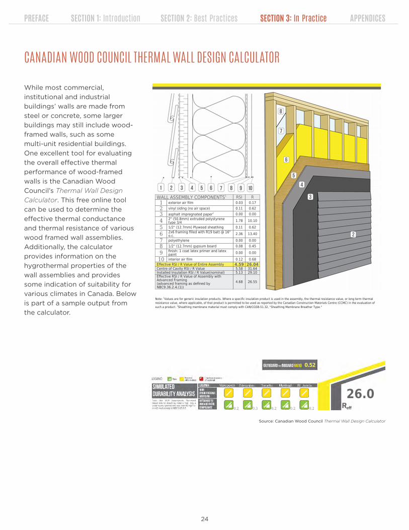
While most commercial,
institutional and industrial
buildings’ walls are made from
steel or concrete, some larger
buildings may still include wood-
framed walls, such as some
multi-unit residential buildings.
One excellent tool for evaluating
the overall effective thermal
performance of wood-framed
walls is the Canadian Wood
Council’s Thermal Wall Design
Calculator. This free online tool
can be used to determine the
effective thermal conductance
and thermal resistance of various
wood framed wall assemblies.
Additionally, the calculator
provides information on the
hygrothermal properties of the
wall assemblies and provides
some indication of suitability for
various climates in Canada. Below
is part of a sample output from
the calculator.
WALL ASSEMBLY COMPONENTS1 RSI R1 exterior air film 0.03 0.172 vinyl siding (no air space) 0.11 0.623 asphalt impregnated paper2 0.00 0.00
4 2" (50.8mm) extruded polystyrenetype 3/4 1.78 10.10
5 1/2" (12.7mm) Plywood sheathing 0.11 0.62
6 2x6 framing filled with R19 batt @ 16"o.c. 2.36 13.40
7 polyethylene 0.00 0.008 1/2" (12.7mm) gypsum board 0.08 0.45
9 finish: 1 coat latex primer and latexpaint 0.00 0.00
10 interior air film 0.12 0.68Effective RSI / R Value of Entire Assembly 4.59 26.04Centre of Cavity RSI / R Value 5.58 31.64Installed Insulation RSI / R Value(nominal) 5.13 29.10Effective RSI / R Value of Assembly withAdvanced Framing(advanced framing as defined byNBC9.36.2.4.(1))
4.68 26.55
Note: 1Values are for generic insulation products. Where a specific insulation product is used in the assembly, the thermal resistance value, or long term thermalresistance value, where applicable, of that product is permitted to be used as reported by the Canadian Construction Materials Centre (CCMC) in the evaluation ofsuch a product. 2Sheathing membrane material must comply with CAN/CGSB-51.32, "Sheathing Membrane Breather Type."
26.0
0.52
0.2 0.3 0.2 0.2 0.2
CANADIAN WOOD COUNCIL THERMAL WALL DESIGN CALCULATOR
Source: Canadian Wood Council Thermal Wall Design Calculator

25
PREFACE SECTION 1: Introduction SECTION 2: Best Practices SECTION 3: In Practice APPENDICES
Designers and contractors who are working with
steel frame or mass walls may find the tables
included with ASHRAE Standard 90.1 to be of help.
ASHRAE Standard 90.1 includes tables to calculate
the assembly U-factors (thermal transmittance) for
a wide variety of wall types. Because there are a lot
of tables, you’ll want to make sure that you’re using
the right tables for the wall type you’re building. One
other thing you’ll want to watch for is that you’ve
got your units right. The ASHRAE tables are all in IP
ASHRAE 90.1 TABLES
AN
SI/ASH
RA
E/IESStandard
90.1-2010(I-P
Edition)117
TABLE A3.3 Assembly U-Factors for Steel-Frame Walls
FramingType andSpacingWidth(ActualDepth)
Cavity InsulationR-Value: Rated
(Effective Installed[see Table A9.2B])
OverallU-Factorfor EntireBase WallAssembly
Overall U-Factor for Assembly of Base Wall Plus Continuous Insulation (Uninterrupted by Framing),
Rated R-Value of Continuous Insulation
R-1.00 R-2.00 R-3.00 R-4.00 R-5.00 R-6.00 R-7.00 R-8.00 R-9.00 R-10.00 R-11.00 R-12.00 R-13.00 R-14.00 R-15.00 R-20.00 R-25.00 R-30.00 R-35.00 R-40.00
Steel Framing at 16 in. on center
3.5 in.depth
None (0.0) 0.352 0.260 0.207 0.171 0.146 0.128 0.113 0.102 0.092 0.084 0.078 0.072 0.067 0.063 0.059 0.056 0.044 0.036 0.030 0.026 0.023
R-11 (5.5) 0.132 0.117 0.105 0.095 0.087 0.080 0.074 0.069 0.064 0.060 0.057 0.054 0.051 0.049 0.046 0.044 0.036 0.031 0.027 0.024 0.021
R-13 (6.0) 0.124 0.111 0.100 0.091 0.083 0.077 0.071 0.066 0.062 0.059 0.055 0.052 0.050 0.048 0.045 0.043 0.036 0.030 0.026 0.023 0.021
R-15 (6.4) 0.118 0.106 0.096 0.087 0.080 0.074 0.069 0.065 0.061 0.057 0.054 0.051 0.049 0.047 0.045 0.043 0.035 0.030 0.026 0.023 0.021
6.0 in.depth
R-19 (7.1) 0.109 0.099 0.090 0.082 0.076 0.071 0.066 0.062 0.058 0.055 0.052 0.050 0.047 0.045 0.043 0.041 0.034 0.029 0.026 0.023 0.020
R-21 (7.4) 0.106 0.096 0.087 0.080 0.074 0.069 0.065 0.061 0.057 0.054 0.051 0.049 0.047 0.045 0.043 0.041 0.034 0.029 0.025 0.022 0.020
Steel Framing at 24 in. on center
3.5 in.depth
None (0.0) 0.338 0.253 0.202 0.168 0.144 0.126 0.112 0.100 0.091 0.084 0.077 0.072 0.067 0.063 0.059 0.056 0.044 0.036 0.030 0.026 0.023
R-11 (6.6) 0.116 0.104 0.094 0.086 0.079 0.073 0.068 0.064 0.060 0.057 0.054 0.051 0.048 0.046 0.044 0.042 0.035 0.030 0.026 0.023 0.021
R-13 (7.2) 0.108 0.098 0.089 0.082 0.075 0.070 0.066 0.062 0.058 0.055 0.052 0.049 0.047 0.045 0.043 0.041 0.034 0.029 0.025 0.023 0.020
R-15 (7.8) 0.102 0.092 0.084 0.078 0.072 0.067 0.063 0.059 0.056 0.053 0.050 0.048 0.046 0.044 0.042 0.040 0.034 0.029 0.025 0.022 0.020
6.0 in.depth
R-19 (8.6) 0.094 0.086 0.079 0.073 0.068 0.064 0.060 0.057 0.054 0.051 0.048 0.046 0.044 0.042 0.041 0.039 0.033 0.028 0.025 0.022 0.020
R-21 (9.0) 0.090 0.083 0.077 0.071 0.066 0.062 0.059 0.055 0.052 0.050 0.048 0.045 0.043 0.042 0.040 0.038 0.032 0.028 0.024 0.022 0.020
Copyrighted material licensed to Jordan MacDonald on 2016-01-22 for licensee's use only. All rights reserved. No further reproduction or distribution is permitted. Distributed for ASHRAE by Thomson Reuters (Scientific) LLC, www.techstreet.com
units. Remember that U-value/U-factor can be either
IP or SI. Since the tables will give you an IP U-factor,
you’ll want to make sure that you convert that to
an SI U-factor before comparing it to the NECB
requirements. Take a look at the “Note on Units”
feature in this Guide for further information.
Below is an example of a table for calculating the
assembly thermal transmittance for steel-frame
walls.
COMcheck is a series of software and web products
designed and made available freely by the US
Department of Energy. Intended to be user-friendly,
COMcheck is a tool that can be used to determine
whether buildings are in compliance with the
prescriptive requirements of ASHRAE 90.1 and some
other state-specific codes.
While the tool doesn’t provide compliance
verification for the NECB prescriptive requirements,
it does include a user-friendly way of determining
assembly U-factors. It includes a software- or
web-based interface for using the ASHRAE 90.1
tables referenced above. The web and software
version of COMcheck also allows users to save
COMcheckSource: ASHRAE Standard 90.1 - 2010
their work, so they can update calculations if
assembly constructions change as designs progress.
Remember, however, that the results of COMcheck
are IP U-values/U-factors. You’ll need to convert to
SI U-values/U-factors if you want to compare the
results to the NECB prescriptive requirements.

26
PREFACE SECTION 1: Introduction SECTION 2: Best Practices SECTION 3: In Practice APPENDICES
Up to this point, the resources
mentioned are for calculating the
effective thermal performance of
building assemblies and dealing
primarily with two-dimensional
heat transfer through simplified
assemblies. At this time, these
tools (ASHRAE 90.1 tables,
COMcheck, and the CWC Thermal
Wall Design Calculator) are all
sufficient to calculate effective
values for demonstrating
compliance with either ASHRAE
90.1 or NECB. In the real world,
however, heat transfer occurs in
three dimensions and building
envelopes are a bit more
complicated. More advanced
methods of calculation will yield
more realistic results.
BUILDING ENVELOPE THERMAL BRIDGING GUIDE
In recognition of this, ASHRAE
developed ASHRAE Research
Project 1365. This project’s
goal was to develop better
tools for building designers to
address thermal bridging in the
building envelope. In effect,
ASHRAE wanted to provide
more realistic predictive models
for understanding how building
assemblies, including thermal
bridges, perform in the real
world. Morrison Hershfield was
contracted to complete the
work. The results of the ASHRAE
Research Project were published
in 2011.
Building Envelope Thermal Bridging Guide
B.5.7
ASHRAE 1365-RP
Detail 5.1.7 Exterior and Interior Insulated 3 5/8″ x 1 5/8″ Steel Stud (16″ o.c) Wall Assembly with Horizontal Z-Girts (24″ o.c.) Supporting Metal Cladding – Clear Wall
View from Interior
View from Exterior
Thermal Performance Indicators
Assembly 1D (Nominal) R-Value R1D R-14.2 (2.5 RSI) +
exterior insulation
Transmittance / Resistance
Uo, Ro
“clear wall” U- and R-value
Surface Temperature Index¹ Ti
0 = exterior temperature 1 = interior temperature
¹Surface temperatures are a result of steady-state conductive heat flow with constant heat transfer coefficients. Limitations are identified in final report.
Nominal (1D) vs. Assembly Performance Indicators Exterior
Insulation 1D R-Value
(RSI)
R1D ft2∙hr∙oF / Btu (m2 K / W)
Ro ft2∙hr∙oF / Btu (m2 K / W)
Uo Btu/ft2 ∙hr ∙oF
(W/m2 K)
R-0 (0) R-14.2 (2.50) R-9.2 (1.62) 0.109 (0.62) R-5 (0.88) R-19.2 (3.38) R-13.4 (2.36) 0.075 (0.42) R-10 (1.76) R-24.2 (4.26) R-16.3 (2.87) 0.061 (0.35) R-15 (2.64) R-29.2 (5.14) R-18.5 (3.25) 0.054 (0.31) R-20 (3.52) R-34.2 (6.02) R-20.5 (3.61) 0.049 (0.28) R-25 (4.40) R-39.2 (6.90) R-22.1 (3.90) 0.045 (0.26)
Temperature Indices R0 R5 R10 R15 R20 R25
Ti1 0.06 0.21 0.28 0.32 0.36 0.38 Min T on sheathing, along girts between studs
Ti2 0.35 0.59 0.68 0.72 0.75 0.78 Max T on sheathing, along studs between girts
Ti1
Ti2
Appendix B - Catalogue Thermal Data Sheets BUILDING ENVELOPE THERMAL BRIDGING GUIDE
Building EnvelopeThermal Bridging Guide
A n A l y s i s ,
A p p l i c A t i o n s &
i n s i g h t s
Since 2011, the results of this study
have been expanded. In 2014,
the Building Envelope Thermal
Bridging Guide was developed by
Morrison Hershfield with funding
from BC Hydro Power Smart,
the Canadian Wood Council,
Fortis BC, FPInnovations and
the BC Homeowner Protection
Office. This free document
provides building designers with
more realistic overall assembly
thermal resistance values that
account for thermal bridging.
The document includes a library
of opaque building assemblies
and transition details, each with
their own thermal performance
characteristics. A sample from the
Guide is on the left.
The Building Envelope Thermal
Bridging Guide is particularly
useful if designers and contractors
want to compare various ways
of designing and constructing
transition details. These would Source: Building Envelope Thermal Bridging Guide, Morrison Hershfield/BC Hydro

27
PREFACE SECTION 1: Introduction SECTION 2: Best Practices SECTION 3: In Practice APPENDICES
include:
• Window/wall transitions,
• Balcony/slab edges,
• Parapet/ceiling connections, and,
• Exterior cladding attachments.
Below is an example from the document that shows
the thermal performance implications of various
floor and balcony slab edge details.
While the Building Envelope Thermal Bridging Guide
goes above and beyond the current calculation
requirements for ASHRAE Standard 90.1 compliance
and NECB compliance, the results it contains are
much more reflective of the real world performance
of building envelopes. It is a great resource for
designers and contractors who want to have a
better understanding about the expected real-world
performance of their building envelopes.PART 1 Building Envelope Thermal Analysis (BETA) BUILDING ENVELOPE THERMAL BRIDGING GUIDE
1-14
Table 1.3: Performance Categories and Default Transmittances for Floor and Balcony Slabs
FLO
OR
AN
D B
ALC
ON
Y SL
AB
S
Performance Category Description and Examples
Linear Transmittance
Btu hr ft F
W m K
Efficient
Fully insulated with only small conductive bypasses Examples: exterior insulated wall and floor slab.
0.12 0.2
Improved
Thermally broken and intermittent structural connections Examples: structural thermal breaks, stand-off shelf angles.
0.20 0.35
Regular
Under-insulated and continuous structural connections Examples: partial insulated floor (i.e. firestop), shelf angles attached directly to the floor slab.
0.29 0.5
Poor
Un-insulated and major conductive bypasses Examples: un-insulated balconies and exposed floor slabs.
0.58 1.0
Table 1.4: Performance Categories and Default Transmittances for Glazing Transitions
GLA
ZIN
G T
RA
NSI
TIO
NS
Performance Category Description and Examples
Linear Transmittance
Btu hr ft F
W m K
Efficient
Well aligned glazing without conductive bypasses Examples: wall insulation is aligned with the glazing thermal break. Flashing does not bypass the thermal break.
0.12 0.2
Regular
Misaligned glazing and minor conductive bypasses Examples: wall insulation is not continuous to thermal break and framing bypasses the thermal insulation at glazing interface.
0.20 0.35
Poor
Un-insulated and conductive bypasses Examples: metal closures connected to structural framing. Un-insulated concrete opening (wall insulation ends at edge of opening).
0.29 0.5
Source: Building Envelope Thermal Bridging Guide, Morrison Hershfield/BC Hydro

28
PREFACE SECTION 1: Introduction SECTION 2: Best Practices SECTION 3: In Practice APPENDICES
GLAZING RATIO CHALLENGES
Depending on building type and design
constraints, having less glazing area can often
be a challenge. Consider for example quick-
service restaurants. These buildings are often
built to a standardized design that features
a relatively large amount of glass. If a project
owner wanted to build one of these buildings in a
colder climate and stick with the design’s typical
glazing ratio they may not be able to meet the
prescriptive requirements. If this were the case,
and the project were required to meet NECB, it
would need to use the performance compliance
pathway. Another reason why the performance
compliance pathway is popular in jurisdictions
that require NECB compliance!
As we mentioned earlier, reducing the glazing area
in a building will most likely improve the thermal
performance of the building envelope. This is
because opaque walls typically have higher effective
insulation values than do windows, doors or curtain
walls.
Some building codes recognize this fact.
Performance compliance pathways in ASHRAE 90.1
and NECB will reflect the impact of glazing ratios
and glazing performance in the proposed building’s
modelled energy consumption. If projects choose
instead to use the prescriptive pathway of some
codes, glazing ratios can be limited to a maximum
amount.
NECB is one code where the prescriptive pathway
limits the glazing ratio. NECB refers to a maximum
“allowable fenestration and door area to gross wall
area ratio (FDWR).” The maximum allowable FDWR
depends on the climate where the project is being
APPROPRIATE GLAZING RATIOSbuilt. Instead of using climate zones like the NECB
does for prescriptive insulation requirements, NECB
uses heating degree days (HDD) to determine the
maximum allowable FDWR.
Projects that are being built in areas with less than
4,000 HDD are allowed to have a ratio of up to 0.40
or 40% windows, doors or curtain walls. Projects
that are being built in areas where there are more
than 7,000 HDD are allowed to have a ratio of up
to 0.20 or 20%. Projects located in areas where
the number of HDD are between 4,000 and 7,000
are required to use the following calculation to
determine the FDWR: Max FDWR = (2,000 – 0.2 *
HDD)/3,000.
Let’s look at two examples here in the province: St.
John’s, NL (4,800 HDD) and Happy Valley-Goose
Bay (6,670 HDD).
As you can see from the calculations, since it’s
colder in Happy Valley-Goose Bay than it is in
St. John’s, it’s probably a good idea to have less
window, door and curtain wall area.
St. John’s Max FDWR
Happy Valley-Goose Bay
Max FDWR
SAMPLE FDWR CALCULATIONS FOR ST. JOHN’S AND HAPPY VALLEY-GOOSE BAY
= (2,000 - 0.2 * 4,800)/3,000
= (2,000 - 960)/3,000
= 0.35 or 35%
= (2,000 - 0.2 * 6,670)/3,000
= (2,000 - 1,334)/3,000
=0.22 or 22%

29
PREFACE SECTION 1: Introduction SECTION 2: Best Practices SECTION 3: In Practice APPENDICES
Execution is important. Even the best designed
building can experience significant failures due
to construction flaws. One strategy to ensure
better execution of design is to specify and verify
functional performance. This concept has gained
traction in the HVAC world, where commissioning
and testing are more common. The same process
can work with building envelopes!
The concept of building envelope commissioning
became formalized with the publication of NIBS
Guideline 3 in 2012. Published by the National
Institute of Building Science, this was the
foundational document for building envelope
commissioning. It provided owners and project
teams with guidance on the process. Since 2012,
further development of the building envelope
commissioning process has been undertaken
by ASTM, the voluntary standards developing
organization. ASTM currently publishes and updates
two documents relating to building envelope
commissioning:
• ASTM E2813 – Standard Practice for Building
Enclosure Commissioning, and
• ASTM E2947 – Standard Guide for Building
Enclosure Commissioning.
ASTM defines building enclosure commissioning as:
“architecture or engineering-related technical
services or both, performed on behalf of the
Owner that implements a quality-focused
process for enhancing the delivery of a project
by focusing on validating during the design
phase and verifying during the construction
phase that the performance of building
enclosure materials, components, assemblies
and systems are designed and installed to meet
the Owner’s Project Requirements.” (ASTM
E2947)
In essence, the process attempts to ensure that
designs are validated through reviews prior to
construction and that construction is verified
SPECIFYING AND VERIFYING FUNCTIONAL PERFORMANCE
An Authoritative Source of Innovative Solutions for the Built Environment
National Institute ofBUILDING SCIENCES
NIBS Guideline 3-2012Building Enclosure Commissioning Process BECx This Guideline is for Use with ASHRAE Guideline 0-2005: The Commissioning Process
April 2012
through testing and visual inspection. The extent
to which an owner will want to embark on
comprehensive building envelope commissioning is
largely a function of budget and perceived value. Full
scale and comprehensive envelope commissioning
is still relatively rare. Design reviews and site testing,
however, are becoming more common.
While ASTM E2947 provides project teams with
a general overview of the process, ASTM E2813
provides a list of the tests project teams may wish
to consider to evaluate the functional performance
of building envelope assemblies, components and
materials. Two common field tests are air leakage
testing of windows and water penetration testing
of windows and curtain walls. The ASTM standards

30
PREFACE SECTION 1: Introduction SECTION 2: Best Practices SECTION 3: In Practice APPENDICES
relating to these field tests are ASTM E783 and
ASTM E1105 respectively.
It’s important to understand that testing standards
don’t specify expected functional performance
levels. The expected functional performance of
building envelope products like windows, doors, or
curtain walls depends on their rated characteristics.
Most building products undergo standardized
laboratory testing to classify their functional
performance characteristics (heat transfer, air
infiltration, water penetration resistance, etc.). In
situ field performance should relate in some way to
these laboratory tests. It’s usually up to an architect
or building envelope consultant to specify an
appropriate functional performance level.

31
PREFACE SECTION 1: Introduction SECTION 2: Best Practices SECTION 3: In Practice APPENDICES
A REVIEWNow that we have a better sense of what’s needed to improve building envelope
performance, you’ll appreciate why it’s important to:
Know your climate zone
Know the difference between effective and nominal insulation values
Integrate strategies to increase the effective thermal resistance of your
building assembly
Pay attention to the details when designing and building
Choose “appropriate” glazing ratios when possible
Choose higher performance glazing systems when possible
Consider the thermal bridging impacts of transition details and wall
assembly choices
Understand the tools available to help you design and construct higher
performing building envelopes
Understand the value of specifying and verifying functional performance
If you’re interested in learning more about any of these important strategies, we
suggest browsing through the referenced resources. Links and descriptions are
included in Appendix B.

32
PREFACE SECTION 1: Introduction SECTION 2: Best Practices SECTION 3: In Practice APPENDICES
APPENDICES

33
PREFACE SECTION 1: Introduction SECTION 2: Best Practices SECTION 3: In Practice APPENDICES
OFFICIAL NAME CLIMATE ZONE
Admirals Beach 6
Anchor Point 7a
Appleton 6
Aquaforte 6
Arnold’s Cove 6
Avondale 6
Badger 7a
Baie Verte 7a
Baine Harbour 6
Bauline 6
Bay Bulls 6
Bay de Verde 6
Bay L’Argent 6
Bay Roberts 6
Baytona 6
Beachside 7a
Bellburns 7a
Belleoram 6
Birchy Bay 7a
Bird Cove 7a
Bishop’s Cove 6
Bishop’s Falls 6
Bonavista 6
Botwood 6
Branch 6
Brent’s Cove 7a
Brighton 7a
Brigus 6
Bryant’s Cove 6
Buchans 7a
Burgeo 6
Burin 6
Burlington 7a
Burnt Islands 6
Campbellton 6
Cape Broyle 6
Cape St. George 6
Carbonear 6
Carmanville 7a
Cartwright 7b
Centreville-Wareham-Trinity 7a
OFFICIAL NAME CLIMATE ZONE
Chance Cove 6
Change Islands 7a
Channel-Port aux Basques 6
Chapel Arm 6
Charlottetown (Labrador) 7b
Clarenville 6
Clarke’s Beach 6
Coachman’s Cove 7a
Colinet 6
Colliers 6
Come By Chance 6
Comfort Cove-Newstead 6
Conception Bay South 6
Conception Harbour 6
Conche 7a
Cook’s Harbour 7a
Cormack 7a
Corner Brook 6
Cottlesville 6
Cow Head 7a
Cox’s Cove 6
Crow Head 6
Cupids 6
Daniel’s Harbour 7a
Deer Lake 7a
Dover 7a
Duntara 6
Eastport 6
Elliston 6
Embree 6
Englee 7a
English Harbour East 6
Fermeuse 6
Ferryland 6
Flatrock 6
Fleur de Lys 7a
Flower’s Cove 7a
Fogo Island 7a
Forteau 7b
Fortune 6
Fox Cove-Mortier 6
Fox Harbour 6
CLIMATE ZONES
APPENDIX A – MUNICIPALITIES BY CLIMATE ZONE
Zone 6 Zone 7a Zone 7b Zone 8
This Appendix lists Newfoundland and Labrador’s municipalities by climate zone, as referenced by the
National Building Code of Canada (NBC) and the National Energy Code of Canada for Buildings (NECB).

34
PREFACE SECTION 1: Introduction SECTION 2: Best Practices SECTION 3: In Practice APPENDICES
OFFICIAL NAME CLIMATE ZONE
Frenchman’s Cove 6
Gallants 6
Gambo 6
Gander 7a
Garnish 6
Gaskiers-Point La Haye 6
Gaultois 6
Gillams 6
Glenburnie-Birchy Head-Shoal Brook 6
Glenwood 6
Glovertown 6
Goose Cove East 7a
Grand Bank 6
Grand Falls-Windsor 6
Grand Le Pierre 6
Greenspond 7a
Hampden 7a
Hant’s Harbour 6
Happy Adventure 6
Happy Valley-Goose Bay 7b
Harbour Breton 6
Harbour Grace 6
Harbour Main-Chapel’s Cove-Lakeview 6
Hare Bay 7a
Hawke’s Bay 7a
Heart’s Content 6
Heart’s Delight-Islington 6
Heart’s Desire 6
Hermitage-Sandyville 6
Holyrood 6
Hopedale 8
Howley 7a
Hughes Brook 6
Humber Arm South 6
Indian Bay 7a
Irishtown-Summerside 6
Isle aux Morts 6
Jackson’s Arm 7a
Keels 6
King’s Cove 6
King’s Point 7a
Kippens 6
La Scie 7a
Labrador City 8
Lamaline 6
L’Anse au Clair 7b
L’Anse au Loup 7b
Lark Harbour 6
Lawn 6
OFFICIAL NAME CLIMATE ZONE
Leading Tickles 6
Lewin’s Cove 6
Lewisporte 6
Little Bay 6
Little Bay East 6
Little Bay Islands 7a
Little Burnt Bay 6
Logy Bay-Middle Cove-Outer Cove 6
Long Harbour-Mount Arlington Heights 6
Lord’s Cove 6
Lourdes 6
Lumsden 7a
Lushes Bight-Beaumont-Beaumont North 7a
Main Brook 7a
Makkovik 7b
Mary’s Harbour 7b
Marystown 6
Massey Drive 6
McIver’s 6
Meadows 6
Middle Arm 7a
Miles Cove 7a
Millertown 7a
Milltown-Head of Bay D’Espoir 6
Ming’s Bight 7a
Morrisville 6
Mount Carmel-Mitchells Brook-St. Catherine’s 6
Mount Moriah 6
Mount Pearl 6
Musgrave Harbour 7a
Musgravetown 6
Nain 8
New Perlican 6
New-Wes-Valley 7a
Nippers Harbour 7a
Norman’s Cove-Long Cove 6
Norris Arm 6
Norris Point 7a
North River 6
North West River 7b
Northern Arm 6
Old Perlican 6
Pacquet 7a
Paradise 6
Parker’s Cove 6
Parsons Pond 7a
Pasadena 7a
Peterview 6
Petty Harbour-Maddox Cove 6
CLIMATE ZONES Zone 6 Zone 7a Zone 7b Zone 8

35
PREFACE SECTION 1: Introduction SECTION 2: Best Practices SECTION 3: In Practice APPENDICES
CLIMATE ZONES Zone 6 Zone 7a Zone 7b Zone 8
OFFICIAL NAME CLIMATE ZONE
Pilley’s Island 7a
Pinware 7b
Placentia 6
Point au Gaul 6
Point Lance 6
Point Leamington 6
Point May 6
Point of Bay 6
Pool’s Cove 6
Port Anson 7a
Port au Choix 7a
Port au Port East 6
Port au Port West-Aguathuna-Felix Cove 6
Port Blandford 6
Port Hope Simpson 7b
Port Kirwan 6
Port Rexton 6
Port Saunders 7a
Portugal Cove South 6
Portugal Cove-St. Philip’s 6
Postville 7b
Pouch Cove 6
Raleigh 7a
Ramea 6
Red Bay 7b
Red Harbour 7a
Reidville 7a
Rencontre East 6
Renews-Cappahayden 6
Rigolet 7b
River of Ponds 7a
Riverhead 6
Robert’s Arm 7a
Rocky Harbour 7a
Roddickton-Bide Arm 7a
Rose Blanche-Harbour Le Cou 6
Rushoon 6
Salmon Cove 6
Salvage 6
Sandringham 6
Sandy Cove 6
Seal Cove, F.B 6
Seal Cove, W.B 7a
Small Point-Adam’s Cove-
Blackhead-Broad Cove 6
South Brook 7a
South River 6
Southern Harbour 6
OFFICIAL NAME CLIMATE ZONE
Spaniard’s Bay 6
Springdale 7a
St. Alban’s 6
St. Anthony 7a
St. Bernard’s-Jacques Fontaine 6
St. Brendan’s 7a
St. Bride’s 6
St. George’s 6
St. Jacques-Coomb’s Cove 6
St. John’s 6
St. Joseph’s 6
St. Lawrence 6
St. Lewis 7b
St. Lunaire-Griquet 7a
St. Mary’s 6
St. Paul’s 7a
St. Shott’s 6
St. Vincent’s-St. Stephen’s-Peter’s River 6
Steady Brook 6
Stephenville 6
Stephenville Crossing 6
Summerford 6
Sunnyside (Trinity Bay) 6
Terra Nova 6
Terrenceville 6
Tilt Cove 7a
Torbay 6
Traytown 6
Trepassey 6
Trinity 6
Trinity Bay North 6
Triton 7a
Trout River 6
Twillingate 6
Upper Island Cove 6
Victoria 6
Wabana 6
Wabush 8
West St. Modeste 7b
Westport 7a
Whitbourne 6
Whiteway 6
Winterland 6
Winterton 6
Witless Bay 6
Woodstock 7a
Woody Point 6
York Harbour 6

36
PREFACE SECTION 1: Introduction SECTION 2: Best Practices SECTION 3: In Practice APPENDICES
APPENDIX B – FURTHER RESOURCES
American Society of Heating, Refrigerating, and Air-Conditioning Engineers
(ASHRAE) www.ashrae.org : ASHRAE, founded in 1894, is a global society
advancing human well-being through sustainable technology for the built
environment. The Society and its members focus on building systems, energy
efficiency, indoor air quality, refrigeration and sustainability within the industry.
ASTM International www.astm.org : ASTM International is a globally recognized
leader in the development and delivery of voluntary consensus standards. Today,
over 12,000 ASTM standards are used around the world to improve product
quality, enhance health and safety, strengthen market access and trade, and build
consumer confidence.
Building Envelope Design Guide www.wbdg.org/design/envelope.php : The
National Institute of Building Sciences (NIBS) under guidance from the Federal
Envelope Advisory Committee has developed this comprehensive guide for
exterior envelope design and construction for institutional / office buildings.
Building Envelope Thermal Bridging Guide www.bchydro.com/thermalguide :
This comprehensive online guide provides: a catalogue of thermal performance
of common envelope assemblies and interface details; outlines information
needed for thermal bridging design and whole-building energy simulations; and,
evaluates cost effectiveness of improving the building envelope through different
methods, building types and climates.
Building Science Corporation www.buildingscience.com : The resources available
on this website combine building physics, systems design concepts, and an
awareness of sustainability to promote the design and construction of buildings
that aim to be more durable, healthier, more sustainable and more economical.
Canada Green Building Council (CaGBC) www.cagbc.org : The Canada Green
Building Council is a not-for-profit, national organization that has been working
since 2002 to advance green building and sustainable community development
practices in Canada. The CaGBC is the license holder for the LEED green building
rating system in Canada.
Canadian Mortgage and Housing Corporation (CMHC) www.cmhc-schl.gc.ca :
CMHC’s website provides information, resources, and case studies on important
building research related to energy efficiency and green building. The CMHC is
one of Canada’s leading organizations dealing with mortgage loan insurance,
mortgage-backed securities, and housing policy and programs.

37
PREFACE SECTION 1: Introduction SECTION 2: Best Practices SECTION 3: In Practice APPENDICES
Canadian Wood Council Wall Thermal Design Calculator www.cwc.ca/resources/
wall-thermal-design : The purpose of this online tool and calculator is to provide
designers with prescriptive wood wall assembly solutions complying with
national energy efficiency requirements. This tool is meant to provide enough
information that architects, designers, engineers, consultants and contractors can
quickly determine suitable wall assemblies for each climate zone in Canada with
confidence.
COMcheck www.energycodes.gov/comcheck : The COMcheck product group makes
it easy for architects, builders, designers, and contractors to determine whether
new commercial or high-rise residential buildings, additions, and alterations meet
the requirements of the International Energy Conservation Code and ASHRAE
Standard 90.1. COMcheck also includes a simplified method for calculating the
effective thermal conductance of building assemblies.
National Institute of Building Sciences (NIBS) www.nibs.org/ : The National
Institute of Building Sciences is a US-based non-profit, non-governmental
organization that brings together representatives of government, the professions,
industry, labour and consumer interests, and regulatory agencies to focus on the
identification and resolution of problems and potential problems that hamper the
construction of safe, affordable structures for housing, commerce and industry
throughout the United States.
National Research Council Canada (NRC) www.nrc-cnrc.gc.ca : As Canada’s
premier organization for research and development, the NRC provides access to a
large database of high quality research publications. The NRC is also responsible
for developing national model construction codes such as the National Building
Code of Canada (NBC) and the National Energy Code of Canada for Buildings
(NECB).
Office of Climate Change and Energy Efficiency www.exec.gov.nl.ca/exec/cceeet/ :
This department of the Government of Newfoundland and Labrador links to reports
and websites outlining the Government’s strategy and policy development on
climate change and energy efficiency.
Turn Back the Tide www.turnbackthetide.ca : This website from the Government
of Newfoundland and Labrador provides important information for homeowners,
businesses and communities on how to save energy and become greener.

38
PREFACE SECTION 1: Introduction SECTION 2: Best Practices SECTION 3: In Practice APPENDICES
APPENDIX C – GLOSSARY OF TERMS
ASHRAE 90.1 Energy Standard for Buildings Except for Low-Rise Residential
Buildings
Building Envelope the parts of the building that separate the conditioned space
inside from the unconditioned space outdoors
Climate Zone an area that has roughly the same heating requirements
Effective Insulation Value takes into account all the components of an assembly, not just
the thermal resistance of the insulation in the assembly
Energy Model computer software that uses proposed construction details,
occupant behaviour, and mechanical systems to predict the
energy efficiency of a building
Fenestration refers to building envelope assemblies that transfer visible light.
These include windows, clerestories, skylights, translucent wall
panels, glass block assemblies, sliding glass doors, curtain walls,
etc.
Heating Degree Days reflect the demand for energy to heat a building. A measure
of how much and for how long the temperature outside stays
below a certain level.
National Building Code of Canada the foundation of design and construction regulations across
Canada
National Energy Code of Canada model national energy code for buildings in Canada. This code
for Buildings (NECB) is a requirement in some Canadian jurisdictions.
Nominal Insulation Value the insulation value of individual building products
Performance Compliance Pathway achieving energy efficiency code compliance by showing that
a proposed building is as energy efficient as, or more energy
efficient than, a building meeting prescriptive requirements.
This is proven through energy modelling.
Prescriptive Compliance Pathway achieving energy efficiency code compliance by meeting
the listed requirements for each building component.
RSI a measure of thermal resistance, or how effective a building
material is at minimizing heat loss. The same concept as
R-value but uses the metric system.

39
PREFACE SECTION 1: Introduction SECTION 2: Best Practices SECTION 3: In Practice APPENDICES
R-Value a measure of thermal resistance, or how effective a building
material is at minimizing heat loss. The same concept as RSI
but uses the imperial (US) measurement system.
Thermal Break using continuous insulation between building components with
lower insulation values. The purpose is to reduce thermal
bridging.
Thermal Bridge occurs where an area of insulation is broken by material that is
prone to heat loss
U-Factors/U-Values a measure of thermal conductance, or how much heat loss
occurs through a building material. Can be either metric (SI) or
imperial (IP). Often used when referring to windows, doors, and
skylights. Also used by NECB and ASHRAE 90.1 to denote
prescriptive building envelope insulation requirements.


![Innovating Better Buildings Final[1]](https://img.dokumen.tips/doc/110x75/549e768ab3795991618b46a9/innovating-better-buildings-final1.jpg)


