Embed Size (px)
Citation preview

GUIDANCE TO SHAFTS FOR SMOKE CONTROL
» A useful guide to practical smoke shaft principles and specifications
FIRE SAFETY
Incorporating the:

Smoke shafts originated from research carried out by BRE and presented in a report in 2002 entitled ‘Smoke Shafts Protecting Fire Fighting Shafts, Their Performance and Design’.
This report specifically looked at fire-fighting shafts and proposed natural ventilation – with the output being commonly known as the ‘BRE Shaft’. The desire to reduce the space occupied by the ventilation system led to the development and common acceptance of mechanically ventilated shafts to provide both firefighting and means of escape protection.
In Common UsageSuch systems are now the most commonly employed smoke control measure for high-rise buildings, overtaking the other available approaches: automatic opening vents and pressurisation.
‘Smoke shaft’ is the common term for ventilation systems in the lobbies of tall buildings, used to maintain tenable conditions in the common escape routes in the event of a fire in the building.
This document is a practical guide to the implementation of smoke shaft systems for regular multi-storey buildings up to 20 storeys in height. For mechanical ventilation, those with a single shaft extracting from a lobby with make-up air being drawn from the stairwell.
NOTE - Complex bespoke designs, for example those using twin shafts with reversible fans, fall outside the scope of this guidance and the design of such would require the services of a suitably qualified fire engineer.
2
Smoke Shafts - An Overview
Origins
3
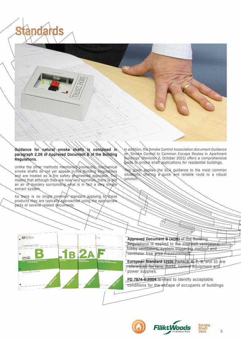
Approved Document B (ADB) of the Building Regulations is applied to the stairwell ventilators, lobby ventilators, system triggering method and ventilator free area measurement.
European Standard 12101 Parts 3, 6, 7, 9, and 10 are referenced for fans, ducts, control equipment and power supplies.
PD 7974-6:2004 is used to identify acceptable conditions for the escape of occupants of buildings.
Guidance for natural smoke shafts is contained in paragraph 2.26 of Approved Document B of the Building Regulations.
Unlike the other methods mentioned previously, mechanical smoke shafts do not yet appear in the Building Regulations and are treated as a fire safety engineered approach. This means that although they are now very common, there is still an air of mystery surrounding what is in fact a very simple extract system.
As there is no single common standard applying to these products they are typically approached using the appropriate parts of several related documents.
In addition, the Smoke Control Association document Guidance on ‘Smoke Control to Common Escape Routes in Apartment Buildings’ (Revision 2, October 2015) offers a comprehensive guide to smoke shaft applications for residential buildings.
This guide applies the SCA guidance to the most common situations, offering a quick and reliable route to a robust solution.
Standards
4
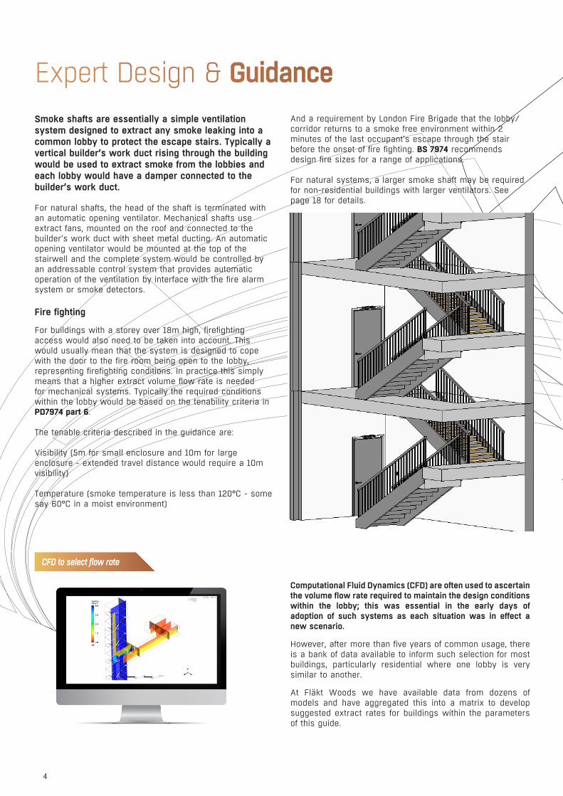
Smoke shafts are essentially a simple ventilation system designed to extract any smoke leaking into a common lobby to protect the escape stairs. Typically a vertical builder’s work duct rising through the building would be used to extract smoke from the lobbies and each lobby would have a damper connected to the builder’s work duct.
For natural shafts, the head of the shaft is terminated with an automatic opening ventilator. Mechanical shafts use extract fans, mounted on the roof and connected to the builder’s work duct with sheet metal ducting. An automatic opening ventilator would be mounted at the top of the stairwell and the complete system would be controlled by an addressable control system that provides automatic operation of the ventilation by interface with the fire alarm system or smoke detectors.
Fire fighting
For buildings with a storey over 18m high, firefighting access would also need to be taken into account. This would usually mean that the system is designed to cope with the door to the fire room being open to the lobby, representing firefighting conditions. In practice this simply means that a higher extract volume flow rate is needed for mechanical systems. Typically the required conditions within the lobby would be based on the tenability criteria in PD7974 part 6.
The tenable criteria described in the guidance are:
Visibility (5m for small enclosure and 10m for large enclosure - extended travel distance would require a 10m visibility)
Temperature (smoke temperature is less than 120°C - some say 60°C in a moist environment)
And a requirement by London Fire Brigade that the lobby/corridor returns to a smoke free environment within 2 minutes of the last occupant’s escape through the stair before the onset of fire fighting. BS 7974 recommends design fire sizes for a range of applications.
For natural systems, a larger smoke shaft may be required for non-residential buildings with larger ventilators. See page 18 for details.
Expert Design & Guidance
Computational Fluid Dynamics (CFD) are often used to ascertain the volume flow rate required to maintain the design conditions within the lobby; this was essential in the early days of adoption of such systems as each situation was in effect a new scenario.
However, after more than five years of common usage, there is a bank of data available to inform such selection for most buildings, particularly residential where one lobby is very similar to another.
At Fläkt Woods we have available data from dozens of models and have aggregated this into a matrix to develop suggested extract rates for buildings within the parameters of this guide.
CFD to select flow rate

5
We have also recently released the NEW Smoke Shaft Selection tool helping to de-risk the early stage design…available now through our fan selector software.
To activate your account please contact [email protected]
Fläkt Woods Selection Tool
LABC Approved
Did you know our Smoke Shaft Vent System has been approved by LABC?
What does that mean?Local Authority Building Control approval means that the building control sign-off is a quick and pain free as the system is pre-approved in its entirety.
Although others have LABC approval for the system concept, they would need to detail exactly how the system has been designed for each project, typically providing CFD Analysis as part of this submittal.
LABC approval of the common system design allows for this process to be shortened and de-risked as CFD Analysis has been completed for the minimum and maximum extents of our system as well as for a database of projects designed to the standard solution.
Key Benefits:• De-mystifying the design process• Suitable for single-stair buildings over 11m in height• Pre-approved system design with LABC
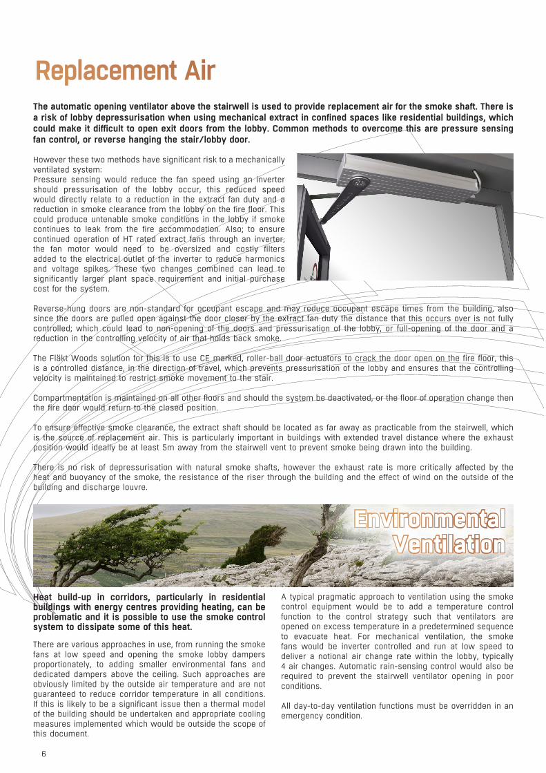
The automatic opening ventilator above the stairwell is used to provide replacement air for the smoke shaft. There is a risk of lobby depressurisation when using mechanical extract in confined spaces like residential buildings, which could make it difficult to open exit doors from the lobby. Common methods to overcome this are pressure sensing fan control, or reverse hanging the stair/lobby door.
However these two methods have significant risk to a mechanically ventilated system:Pressure sensing would reduce the fan speed using an inverter should pressurisation of the lobby occur, this reduced speed would directly relate to a reduction in the extract fan duty and a reduction in smoke clearance from the lobby on the fire floor. This could produce untenable smoke conditions in the lobby if smoke continues to leak from the fire accommodation. Also; to ensure continued operation of HT rated extract fans through an inverter, the fan motor would need to be oversized and costly filters added to the electrical outlet of the inverter to reduce harmonics and voltage spikes. These two changes combined can lead to significantly larger plant space requirement and initial purchase cost for the system.
Reverse-hung doors are non-standard for occupant escape and may reduce occupant escape times from the building, also since the doors are pulled open against the door closer by the extract fan duty the distance that this occurs over is not fully controlled; which could lead to non-opening of the doors and pressurisation of the lobby, or full-opening of the door and a reduction in the controlling velocity of air that holds back smoke.
The Fläkt Woods solution for this is to use CE marked, roller-ball door actuators to crack the door open on the fire floor, this is a controlled distance, in the direction of travel, which prevents pressurisation of the lobby and ensures that the controlling velocity is maintained to restrict smoke movement to the stair.
Compartmentation is maintained on all other floors and should the system be deactivated, or the floor of operation change then the fire door would return to the closed position.
To ensure effective smoke clearance, the extract shaft should be located as far away as practicable from the stairwell, which is the source of replacement air. This is particularly important in buildings with extended travel distance where the exhaust position would ideally be at least 5m away from the stairwell vent to prevent smoke being drawn into the building.
There is no risk of depressurisation with natural smoke shafts, however the exhaust rate is more critically affected by the heat and buoyancy of the smoke, the resistance of the riser through the building and the effect of wind on the outside of the building and discharge louvre.
Replacement Air
Heat build-up in corridors, particularly in residential buildings with energy centres providing heating, can be problematic and it is possible to use the smoke control system to dissipate some of this heat.
There are various approaches in use, from running the smoke fans at low speed and opening the smoke lobby dampers proportionately, to adding smaller environmental fans and dedicated dampers above the ceiling. Such approaches are obviously limited by the outside air temperature and are not guaranteed to reduce corridor temperature in all conditions. If this is likely to be a significant issue then a thermal model of the building should be undertaken and appropriate cooling measures implemented which would be outside the scope of this document.
A typical pragmatic approach to ventilation using the smoke control equipment would be to add a temperature control function to the control strategy such that ventilators are opened on excess temperature in a predetermined sequence to evacuate heat. For mechanical ventilation, the smoke fans would be inverter controlled and run at low speed to deliver a notional air change rate within the lobby, typically 4 air changes. Automatic rain-sensing control would also be required to prevent the stairwell ventilator opening in poor conditions.
All day-to-day ventilation functions must be overridden in an emergency condition.
EnvironmentalVentilation
6

BS 7346-8:2013 Part 8 - Installation:“The nature and quality of the installation work needs to be such as to ensure the integrity of the smoke control system and minimise the duration and extent of any disablement of the system during maintenance or modifications.
Penetration of construction (e.g. for the passage of cables, conduit, trunking or tray) ought to be made good to prevent the free passage of fire or smoke, regardless of whether the construction has a recognised degree of fire resistance.”
BS 7346-8:2013 Part 8 - Commissioning:“The process of commissioning involves thorough testing of the installed smoke control equipment, including interactions with other systems.
The responsibility of the commissioning engineer is to verify that the system operates in the manner designed and that the installation workmanship is of an adequate standard. It is therefore necessary for the commissioning engineer to be provided with the agreed specification for the system.”
Installation & Commissioning
The Regulatory Reform (Fire Safety) Order 2005 (RRO) dictates that a building’s “responsible person” (generally a building owner, manager or FM) has to ensure proper operational service and maintenance of smoke control systems.
Smoke shafts are life-critical aspects of a building’s operation so their proper maintenance is vital. Many components come under the scheduled service recommendations of BS 9999, and the latest standard on smoke control (BS 7346-8:2013 Part 8) states that:
“Smoke control equipment should only be maintained by
a competent person with specialist knowledge of smoke control systems, adequate access to spares and sufficient information regarding the system.”
It is important to bear in mind the fact the smoke control systems are more than just a parts list. While one aspect may be apparently operational, it must also be suitably operational in relation to the rest of the system.
Software maintenance, too, is important, and the latest updates should always be installed to ensure maximum performance.
Service & Maintenance
Installation should be undertaken by a specialist contractor who understands the working relationship of each installed element of the shaft system.
Prior to handover, the commissioning process needs to be able to prove the effectiveness of the system in a variety
of test operation scenarios, in accordance with the agreed ‘cause and effect’.
Guidance exists to govern the quality of installation and the extent and scope of commissioning, for example:
7

8
System Components
The extract shaft or duct shall meet the requirements for fire resistance for a period at least equal to the highest period of fire resistance through which the ductwork passes, when tested and classified in accordance with prEN 13501-3. In practice this will usually mean a minimum of 1 hour fire resistance.
The internal surface should be smooth and the maximum air leakage should be 3.85m3/hour at 50Pa pressure difference, as specified in the pressurisation standard EN12101 Part 6. A pressure test should be undertaken to prove the leakage prior to installation of the system.
For mechanical shafts, the minimum free area is typically 0.6m2 with an aspect ratio of 2:1 with the shaft rising vertically with minimal changes in direction or shape throughout its travel. The recommended size for ease of connection to roof extract equipment is 800mm x 800mm.
For natural shafts ADB specifies a minimum internal free area of 1.5m2, with a minimum dimension in any direction of 0.85m. The recommended internal shaft dimensions for ease of roof vent sizing are 1.2m x 1.3m. Where there is a risk of falling into the shaft then floor grids may be required at intermediate kevels and these should maintain a minimum free area of 1.0m2. Shafts should extend a minimum of 2.5m above the ceiling of the highest floor, be at least 0.5m above and 2.0m distance from any roof structures. In non-residential buildings requiring firefighting protection (those with a storey above 18m) the shaft free area required is 3.0m2 (recommended dimensions 1.5m x 2.0m) and the construction should be 2hr fire resistant.
Builder’s Work Shaft
Control System
The control system should comply with EN12101-09 where applicable, and sensitive equipment such as inverters and PLCs should be located out of the fire zone.
The control system may be designed specifically for the building, or be a modular standardised product that can be configured to the building. Most residential applications will suit the modular approach, with local zone control panels located throughout the building communicating with a central processor usually located at the fan position, and a HMI panel at a convenient location that is used for commissioning and testing. Triggering of the system may be from dedicated smoke detectors purely for the operation of the smoke control system, or through interface with a building smoke detection system compliant with BS5839 part 1, L5 classification. Manual call points should be orange and, where located adjacent to a ventilator on a fire floor, should simulate an alarm on that floor.
Manual control switches for fire fighter use should be located adjacent to the fire service access point and be clearly labelled ‘Smoke Extract’. Where the system incorporates a higher extract duty for firefighting access, manual boost switches should be positioned on each floor for fire brigade use.

9
The ventilator above the stairwell will primarily be used as an air inlet for the smoke shaft and should have a minimum free area of 1.0m2 when measured in accordance with diagram C7 of ADB.
The ventilator should comply with EN12101-02.
Stairwell Ventilator
Smoke Exhaust Plant
For mechanical shafts, extract fans should comply with EN12101-03 and a standby fan is required in case of fan failure. The selection of the appropriate temperature rating should be dictated by the results of any design calculations or cfd modeling, however, based on previous project data, a rating of 300ºC for 1 hour will be suitable for most residential situations.
Ventilators at the head of natural shafts should be to the same standard as stairwell ventilators, complying with EN12101-02. For residential buildings a free area of 1.0m2 is required, while for firefighting shafts the free area should be 1.5m2.
The ventilator connecting the lobby to the builder’s work shaft may be a door type or a damper. The basic requirements are for it to open on the fire floor to exhaust smoke and for the remaining floors to remain closed, preventing smoke spread and maintaining fire compartmentalisation. There is no specific standard for these products so the two common approaches are to use an E30Sa fire door (with an electrical actuator) or a smoke damper, neither of which will be fully certified for the application but which offer pragmatic solutions.The actuators should be drive open, drive closed rather than a spring-return type.
For natural shafts in all residential buildings the free area of the lobby ventilator is 1.0m2. For firefighting smoke shafts, the ventilator free area is increased to 1.5m2.
In mechanical systems, the free area is calculated according to the required extract volume, and is typically around 0.6m2.
The ventilator should be positioned as close to the ceiling as possible within the lobby, and at least as high as the top of the door from the lobby to the stairwell.
Power Supply & Wiring
The system should have a secondary power supply in case of mains failure in accordance with EN12101-10. This may be from either an independent electricity utility supply or a generator back up supply. Electrical wiring should be of a suitable temperature rating for the application.
For most residential systems FP200 or equivalent is suitable for sensors and devices, while FP400 is commonly used for power supplies to extract plant.
Lobby Ventilator
10
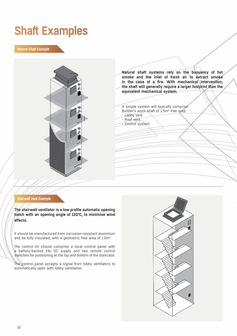
Natural shaft systems rely on the buoyancy of hot smoke and the inlet of fresh air to extract smoke in the case of a fire. With mechanical intervention, the shaft will generally require a larger footprint than the equivalent mechanical system.
A simple system will typically comprise: Builder’s work shaft of 1.5m2 free area- Lobby vent- Roof vent- Control system
The stairwell ventilator is a low profile automatic opening hatch with an opening angle of 120ºC, to minimise wind effects.
It should be manufactured from corrosion-resistant aluminium and be fully insulated, with a geometric free area of 1.0m2.
The control kit should comprise a local control panel with a battery-backed 24v DC supply and two remote control switches for positioning at the top and bottom of the staircase.
The control panel accepts a signal from lobby ventilators to automatically open with lobby ventilation.
Natural Shaft Example
Stairwell Vent Example
Shaft Examples
11
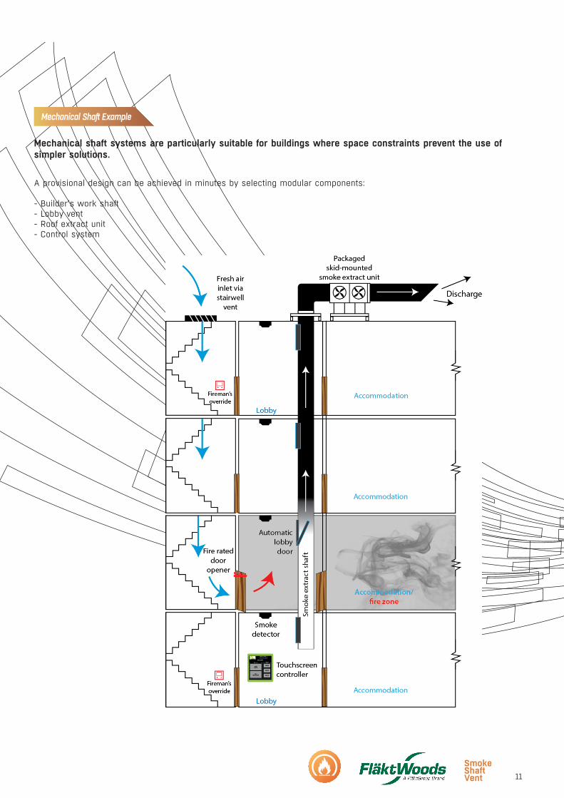
Mechanical shaft systems are particularly suitable for buildings where space constraints prevent the use of simpler solutions.
A provisional design can be achieved in minutes by selecting modular components:
- Builder’s work shaft- Lobby vent- Roof extract unit- Control system
Mechanical Shaft Example

12
Smoke Shaft Vent FAQWHAT IS IT?
The Fläkt Woods Smoke Shaft Vent is a standardised modular mechanical smoke shaft system for protecting lobbies and corridors in tall buildings. It is approved for use in England and Wales through the Local Authority Type Approval scheme.
WHAT TYPE OF BUILDINGS IS IT SUITABLE FOR?
The system is suitable for most tall buildings including residential, commercial, hotels and student accommodation within the following system parameters:• Maximum of 20 storeys• A single extract shaft of 0.6m2 free area with inlet air from a stairwell• Roof suitable for a skid-mounted fan arrangement• A maximum escape travel distance from the accommodation of 15m• Extract shaft to be located a minimum of two-thirds of the total travel distance away from the stair door (see illustration)
CAN IT BE USED FOR FIREFIGHTING SHAFTS?
Yes, the system is suitable for smoke control for both means of escape and firefighting conditions.
WHAT POWER SUPPLIES DO WE NEED TO THE MOTOR CONTROL CENTRE?
The system will require both essential and non-essential 400V 3Ph&N supplies. The standard fan skid only accepts a single 400V 3Ph&N supply; so if both supplies are cabled to the fan skid a skid-mounted Automatic Transfer Switch can be provided to switch to the non-essential supply should the essential supply be lost.
WHAT CABLING DO WE NEED TO INSTALL?
The cabling requirements would be:• Interface panels – 3 core FP200 plus (230V supply) and 2 core FP200 plus (data)• Cabling to the lobby vent and door openers – 3 core FP200 plus• Cabling to the fireman’s override switch – 3 core FP200 plus• Cabling to the HMI – 3 core FP200 plus (230V supply) and 2 core FP200 plus (data)• Cabling to the motor control panel/ATS should be in accordance with BS 8491:2008 and shall be at least Category 2 (minimum FP400) as described in BS 8519:2010

13
ARE FIREMAN’S OVERRIDE SWITCHES NEEDED TO SWITCH BETWEEN MODES?
No, research shows that firefighters are reluctant to use manual controls on active firefighting systems due to lack of familiarity with the intricacies of systems in individual buildings.
“Over-complicated smoke control is the last thing firefighters want when dealing with a challenging, dynamic live fire situation. I’m a big fan of the Fläkt Woods Smoke Vent Shaft system because it’s simple and effective; it removes the frequently complex override controls that firefighters simply don’t have the time to deal with. An automated, standard system protecting building occupants from fires has to be a good thing.” Gary Johnson, Head of Business Fire Safety, South Wales Fire and Rescue Service
WHO IS RESPONSIBLE FOR SYSTEM DESIGN?
The installing contractor is ultimately responsible for system design as for any other building engineering system. The design is pre-configured as part of the system concept and a generic design document forms part of the output from the product selector, together with drawings, BIM models, technical submittals and installation and operation instructions.
DO YOU PRODUCE A CFD TO PROVE PERFORMANCE?
Reference CFD models have been produced for systems at the extremes of the system parameters and these were vetted and approved by the LABC Type Approval process, so providing the building is within the scope of the system then an individual model is not needed.
WHERE DOES AIR INLET FOR THE SYSTEM COME FROM?
Replacement air for the extract system is drawn from the staircase by the controlled partial opening of the lobby/stair door.
HOW DO YOU PREVENT NEGATIVE PRESSURE OR EXCESSIVE DEPRESSURISATION OF THE LOBBY?
The partial opening of the stair door relieves overpressure in the lobby and ensures efficient operation of the system.
DO YOU PROVIDE A SUPPLY AND INSTALL SERVICE?
Yes, although the system is designed for self-installation by competent mechanical and electrical contractors, there is a network of Fläkt Woods-approved installers who can offer a full installation and commissioning service.
HOW IS THE SYSTEM COMMISSIONED?
The system is configured via a menu-driven touch screen and requires no specialist programming skill and full instructions are provided.To comply with the LABC scheme, the system must be certified by a Fläkt Woods-approved inspector.
CAN THE SYSTEM BE USED TO PREVENT CORRIDOR OVERHEATING?
Yes, the system software includes a daily ventilation mode using the existing extract plant to mitigate heat build-up in corridors.

DOES THE SYSTEM COMPLY WITH RELEVANT BRITISH AND EUROPEAN STANDARDS?
Yes, it complies fully with all relevant standards including:
• BS 9991:2011 - Fire safety in the design, management and use of residential buildings• BS 9999:2008 - Code of practice for fire safety in the design, management and use of buildings• Smoke Control Association – Guidance on Smoke Control to Common Escape Routes in Apartment Buildings (Flats and Maisonettes) Revision 2: October 2015• BS 8519:2010 - Selection and installation of fire-resistant power and control cable systems for life safety and firefighting applications• BS EN 12101-2:2003 - Specification for natural smoke and heat exhaust ventilators• BS EN 12101-3:2015 - Specification for powered smoke and heat control ventilators (Fans)• BS EN 12101-8:2011 – Smoke and heat control systems Smoke control dampers• BS ISO 21927-9:2012 - Smoke and heat control systems Specification for control equipment• BS EN 12101-10:2005 - Smoke and heat control systems Power supplies• BS 5839-1:2013 - Fire detection and fire alarm systems for buildings• BS 7346-4:2003 - Functional recommendations and calculation methods for smoke and heat exhaust ventilation systems• BS 7346-8:2013 - Components for smoke control systems Code of practice for planning, design, installation, commissioning and maintenance
DOES THE SYSTEM USE INVERTERS TO CONTROL THE FANS IN EMERGENCY USE?
No, in emergency mode the inverters are bypassed to comply fully with the requirements of EN12101 Part 3:2015, which precludes the use of inverters in emergency mode unless they have been fire tested with the fans or are equipped with additional filters and the fan motors derated by 20%. This standard makes the use of compliant modulating fan systems uneconomical.
WHAT ARE THE MAINTENANCE REQUIREMENTS?
The maintenance requirements are the same as for any other smoke control system and as detailed in the Regulatory Reform Order. It is recommended that the system is tested monthly and inspected/serviced twice per year by a competent person. The Smoke Shaft Vent system has the capability for remote monitoring (additional cost item).Does the control system interface with other building systems?
Yes, the system can communicate directly with BMS and fire alarm systems via a Modbus interface.
Smoke Shaft Vent FAQ
14

Learn More - CPD Training
We currently have several CIBSE approved CPD’s written and presented by our staff who are experienced experts in these fields, approved by CIBSE these count towards your continued professional development hours and points.
CPD COURSE - SMOKE SHAFTS: A PRACTICAL GUIDE
Our presentation investigates mechanical smoke extract shafts as a Fire Engineered solution for means of escape and fire fighter access. We will demonstrate that for many residential buildings there is a commonality between designs that allows for some simplification of the design process.
The Fire Engineered solution shall reference the latest building regulations and guidance documents to ensure best practice of design and correct acceptance criteria. CFD Analysis of the building structure is also discussed to demonstrate the flow of smoke during operation.
We shall introduce a simplified solution for typical building designs for a complete package offer based on an easy selection tool and a modular approach for customisation with the site conditions.
This presentation is certified by CIBSE, we anticipate the presentation will last 45 minutes – 1 hour depending on questions.
To register your interest, please email [email protected]
15

WWW.FLATKWOODS.CO.UK SMOKE SHAFT | 9732GB | 20161124
» To learn more about our offering and get in contact with your nearest sales representative please visit www.flaktwoods.co.uk
With over a century of innovation and expertise to share with our customers, Fläkt Woods is a global leader in Air Technology products and solutions. We specialise in the design and manufacturing of a wide range of products and solutions for Air Movement, Air Treatment, Air Distribution, Air Management and Air Diffusion with focus on two major benefits – Air Comfort and Fire Safety. With market presence in 65 countries we are in a unique position to be a local supplier and an international partner in our customer’s projects.
Our product brands such as SEMCO®, eQ®, eQ Prime®, JM Aerofoil®, Econet®, Veloduct®, Optivent®, Optimix®, Econovent® and Cleanvent® are well-known and trusted by customers all over the world to deliver high quality and energy efficient solutions.


![Smoke extraction and ventilation system for lift shafts · PDF fileAccording to the Model Building Code (MBO) ... according to EN 54-7 LIFT BEAM [- 4.2 -] Motorised linear smoke detector](https://img.dokumen.tips/doc/110x75/5a788b6f7f8b9a77438e9742/smoke-extraction-and-ventilation-system-for-lift-shafts-to-the-model-building-code.jpg)