Embed Size (px)
Citation preview

Guidance sheet for Inspection and testing of Cast Manganese Steel Crossings.
The steps to be followed during Inspection and testing Cast Manganese Steel Crossings with
their references are as below-
(The following text is derived considering testing of Cast Manganese Steel Crossings , or
mentioned otherwise)
SN Action Reference Remarks/ Points to be
take care
1 Arrival of inspecting official in the firm premises:
Checking of documents
Inspection check sheet
ISO Validity, inspection fee PO , DP, old ICs & ITR Etc.
2 Checking of offered
Cast Manganese
Steel and material
Call letter of placed call. Checking of serial number of
offered crossings and material
list as mentioned in PO and Drg
(as the case may be)
3 Inspection during pouring
1.Chemical Analysis
2.Temperature 00C at
melting, tapping & Pouring
IS:12308-1991, approved QAP & as per Clause 4 of IRS/T-29
Once in six month as per extant
practice all activities witnessed
/verified by quality control in
charge and M&C official.
In regular manufacturing firm’s
quality control in charge
witnessed/verified all activities.
Details of the inspection memo-I
of appendix –II of IRST-29/16
are properly verified from the
register
4. Inspection after knockout,
fettling and shot blasting
(Stage –I):
1. Chemical Analysis
2. Surface Defects
( To be done only in case of
developmental vendor)
As per Annexure I, Clause 4 & 6.2.1 of IRS/T-29
For all vendors & in regular
manufacturing firm’s quality
control in-charge witnessed/
verified detachment of integral
test bar and check chemical
analysis as per annexure II and
surface defects and cracks etc.
as per annexure I.
Details of the inspection memo-
II of appendix –II of IRST-29/16
are properly verified from the
register
5. After heat treatment and shot
blasting (Stage –II):
1.Chemical Analysis
2.Surface Defects
3. Impact Bend tests
4.Hardness Test
5.Microstructure & Grain Size
As per Annexure I , II and III
Check and ensure Heat
treatment done properly by go
through Heat treatment graph
as per IRST-29 and Approved
QAP.
Heat treatment graphs are
properly verified in the register
as per para 8.7 of IRST-29

6. Dimensional Check
examination after Heat
Treatment.
As per Clause 10.4.3.5 of IRS/T-29-2016 & relevant drawing of CMS Crossing
Gross dimensions such as
overall length, distance between
actual nose and heel, actual
nose and toe end, height at
different locations, flange
thickness at different locations,
flange way clearance, throat
clearance, flange well depth,
wheel tread at toe end, nose
thickness, nose depression and
off sets bottom, bottom width,
tie thickness, extent of vertical
bend etc. shall be checked and
recorded in inspection memo-IV
as mentioned in Appendix-II of
IRS/T-29
7. Inspection after (Stage –III):
Removal/rectification of
defects by repair welding &
Straightening
As per Clause 10.4.4 of
IRS/T-29
Defect shown in sketch have
been removed by
grinding/gouging
1. Dye penetration test
conducted in presence of
inspecting official showed no
crack before welding.
2. No welding was done
on the casting . or
3. The defects mentioned
in inspe otion memo-III for
this crossing have been
rectified fully by welding in
accordance with the welding
procedure laid down by
RDSO.
4. The removal of
defects/rectification and
straightening has been done
gradually in hydraulic press
and dye penetration test
conducted on the crossing
shows no sign of crack.
No case of permission of
removal/rectification of defects
by welding had been reported
by inspecting official so far.
Generally straightening done if
required.
8. Final dimensional checkup,
Dye Pentration test,
Radiographic test and
magnetic test (Stage-IV/Final
Stage)
As per Clause 10.4.5
6.2.3 - 6.2.5 of IRS/T-29 &
relevant crossing drawing
.Dimensions checklist as per
approved QAP.
All crossings shall be visually
inspected for gross surface
defects at various stages of
inspection. Dye penetrate
Inspection shall be carried out
after final finishing for final
acceptance as per clause
10.4.5. After final inspection and
certification by the Works
Inspector of the firm as per
Clause 15, the crossing shall be
offered finally for dimensional
checkup (as per sequence
shown in Appendix-VI) on the

methods shall be employed
for detection of fine surface
defects. Castings thus
inspected shall be free from
cracks, shrinkage cavities,
scabs, flakes, blisters, lack of
metal, inclusion, porosities,
hot tears, coldshuts and
other harmful defects. Minor
scattered porosities of less
than 4 mm dia and 1.5 mm
depth (provided they are not
closer than 15mm from each
other and not more than
three nos. at a particular
location) shall be considered
acceptable. However, all
such defects have to be in a
location which is at least 300
mm away from tip of the
nose on its either side.
Surface of the casting shall
be reasonably smooth and
free from extraneous
matters.
inspection table/marking table
with the approved gauges/
templates /equipment as
mentioned in Clause 9.2.
The castings shall be visually
inspected for surface defects
employing dye penetrate tests
as necessary.
The casting shall also be tested
for its non-magnetic character
either by portable magnet or by
suitable electro-magnet. The
check will be done on head
surface.
Dimensions of crossings shall
be checked with the help of
gauges /templates, fishing cord,
straight edge, filler gauge etc.
At the discretion and as per
directives of the inspecting
official, the manufacturer shall
produce the non-destructive test
result (to be done in presence
of inspecting official) at the
frequency of 1 in 10 castings as
detailed in Clause 6.2.3.
After the inspecting official(s) is
(are) satisfied that the crossing
conforms to relevant drawing
and specifications, the crossing
shall be accepted finally and the
inspection memo-VI as
mentioned in the Appendix-II
shall be signed.
11. Stamping and issuance of
inspection certificate
As per Clause 16 of IRS/T-
29
Crossing thus cleared shall be
offered to the inspecting official
for necessary stamping with
inspecting official’s steel stamp
insignia. Inspection stamp shall
be marked on top surface of the
left hand wing 25mm away from
heel end. 16.2 After acceptance
of crossing as per Clause
10.4.5.5 and stamping as per
Clause 16.1 above, inspection
certificate shall be issued by the
inspecting official authorized by
the competent authority.
12 Painting As per Clause 17 of IRS/T-
29
17.1 Stamped crossing shall be
thoroughly cleaned to remove
rust, scale dirt and oil and
received primer coats on each
surface to one of the following
schedules:
(a) One coat of ready mixed
paint brushing red lead non-
setting priming to IS: 102(latest
adopted revision in vogue). Or
(b) One coat of ready-mixed
paint, brushing zinc chrome
priming to IS:104(latest adopted
revision in vogue) followed by
one coat of ready mixed paint
and drying red oxide-zinc
chrome, priming to IS:2074
(latest adopted revision in
vogue) . or (c) Two coats of
ready-mixed paint, air drying
red oxide, zinc chrome priming
to IS: 2074(latest adopted
revision in vogue). or (d) Two
coats of red-oxide, zinc
chromate primer to IRS
specification no. P31(latest
adopted revision in vogue). 17.2
The primer coats as indicated in
Clause 17.1(b), (c) and (d) shall
be protected by one finishing
coat of ready-mixed paint,
brushing, finishing, semi-gloss
to IS:123(latest adopted
revision in vogue) 17.3 The
paint shall be applied by brush.
The first priming coat shall be
applied within four hours after
cleaning etc. The second
priming coat shall be applied
when the first priming coat has
dried. The finishing coat shall
be applied when the second
priming coat has dried. The dry
film thickness of the two coats
of primer shall not be less than
40 microns and the complete
system inclusive of finishing
coat not less than 80 microns.
Record of painting process shall
be maintained. 17.4 The
inspecting officials shall check

the quality of paints that will be
used as per relevant
specifications once in two
months or after painting of
every lot of 200 crossings. 17.5
Quality of painting shall be
checked at random once in a
month as and when inspecting
official is available in shop floor.
13 Rejection
As per Clause 14 of IRS/T-
29
Any batch of crossings
produced from the same
melt and/or heat-treated
together under the same
conditions which fails to
comply with the
requirements of the
specifications, shall be
rejected. All rejected
crossings shall be painted
red on both sides of the web
for a distance of 300 mm
from each end, in addition to
such stamp marks as may
be desired by the inspecting
official.
These rejected crossing shall
be cut by gas cutting or by any
other means into minimum two
pieces preferably near middle of
the crossing in order to avoid
mixing up with the crossings
under processing/ finishing /
inspection and shall be kept
stacked separately till their
verification by inspecting official.
A certificate to this effect shall
be enclosed with the next
inspection call.
14 Dispatch As per Clause 18 of IRS/T-
29
All crossings, after approval,
shall be loaded in a systematic
manner to the satisfaction of
inspecting official to avoid any
damage in transit.
15 Testing of fittings As Per IRST-29, relevant
specification and frequency
of testing as approved QAP
Note:
(i) If all the test results are confirming to the specified values as mentioned in the
specification with their latest amendments then issue of IC & DM could be exercised.
(ii) In case of any non- confirming in the test results action as per para-14 of IRST-29 2016
and latest amendments of the specification shall be followed.

Annexure -I
Metallurgical Testing of CMS Crossing for Approved vendor
Inspection of CMS crossing shall be carried out in four stages i.e. Stage-I, Stage-II , Stage-III
and Stage IV (final stage):-
(i) Stage-I: Inspection shall be carried out after knockout/oxy-cutting/shot blasting etc.
(ii) Stage-II: Inspection shall be carried out after heat treatment and shot blasting etc.
(iii) Stage-III: Inspection shall be carried out after removal/rectification of defects and
straightening.
(iv) Stage-IV(Final stage): Inspection shall be carried out after final finishing for final
acceptance Out of these four stage of inspection, Stage (II) is done for Metallurgical &
Dimensional Inspection for approved vendors.
The testing which are conducted by M&C at stage-II for approved vendor are as follows:-
1. Visual Inspection:
(i)All crossings shall be visually inspected for gross surface defects at various stages of
inspection. Dye penetrate methods shall be employed for detection of finer surface defects.
Castings thus inspected shall be free from cracks, shrinkage cavities, scabs, flakes, blisters,
lack of metal, inclusion, porosities, hot tears, cold shuts and other harmful defects. Minor
scattered porosities of less than 4 mm dia and 1.5 mm depth (provided they are not closer
than 15mm from each other and not more than three nos. at a particular location) shall be
considered acceptable. However, all such defects have to be in a location which is at least
300 mm away from tip of the nose on its either side. Surface of the casting shall be
reasonably smooth and free from extraneous matters.
(ii)The crossing shall be free from embedded sand particles and risers, flow off shall be
knocked off, ingate at ends and other thick fins, if any, shall be removed by Arc Air or oxy-
cut. If oxy-cut, then the cut should be at least 25mm away from the crossing body. The
casting shall be suitably shot blasted thereafter, so that they are free from sand etc. and
surface inspection can be done visually by the inspecting official without any difficulty. In no
case, crossing shall be placed on shaker for removal of sands. Fettling & shot blasting shall
be done in such a way so as to avoid any impact to the crossing.
All crossings shall be free from gas pockets, sand holes, cracks, cold shuts and other
injurious defects. Lumps and sharp fins, if any, on the edges of the casting shall be suitably
removed.
The castings shall bear manufacturer’s identification marks, drawing number, serial number
and date of cast. A register shall be maintained by the manufacturer correlating the casting
serial number and heat number and register shall be produced to the Inspecting Authority
for their verification on demand.
Crossing surfaces/areas/locations i.e. running surfaces, non-running surface, highly
stressed locations, nose, wings on either side of nose shall be broadly classified in the
following categories depending upon their criticality from the service considerations, for the
purpose of repair by welding:
Category-I: 300mm of the top of nose, 300mm of the wings on either side of actual nose of
crossing and edges of both top and bottom flanges (upto 25mm from edge).
Category-II: Running surface other than the area mentioned in Category-I.
Category-III: Non-running surface other than the area mentioned in Category-IV and top
surface of “Vee” not coming in contact with running wheels of rolling stock.

Category-IV: Non-vulnerable areas like bearing plates, walls of end sections (excluding
head portion).
At locations covered in category-I, no casting defects shall be permitted.
At locations covered in Category-II, no rectification shall be allowed on the running surface.
Scattered minor defects (excluding cracks) of size less than 4mm dia and upto 1.5mm depth
anywhere on this area of the casting shall be left as such, provided these defects are at a
minimum distance of 15mm from each other and not more than 3 numbers in a particular
location.
At locations covered in Category-III, defects appearing in the crossing surface shall be
permitted to be rectified by welding adopting the usual procedure and precautions at the
discretion of the inspecting official.
At locations covered in Category-IV, surface defects of size<30mm in diameter and depth
<1/3 of thickness may be permitted to be rectified by welding taking necessary precautions
and with the knowledge of the inspecting official and to be recorded in the final inspection
certificate.
SKETCH SHOWING DIFFERENT CATEGORIES OF LOCATION

Annexure -II
2. Chemical Composition:
One integral test bar shall be detached randomly from any crossing in a melt heat batch.
The chemical composition shall be determined by taking sample from the integral test bar so
detached which shall represent the entire melt heat batch.
The steel used for crossings, when analyzed as per relevant parts of IS:12308 or any other
established instrumental method, shall have the following composition:
Constituent Percent
Carbon 1.0 to1.4%
Silicon(Max) 0.5%
Manganese 11.0 to 14.0%
Sulphur(Max) 0.03%
Phosphorus(Max) 0.06%
The ratio of Manganese to Carbon should be minimum 10 : 1. In case of any dispute, the
procedure given in relevant part of IS:12308 shall be the reference method.
Calibration of Spectrometer
Spectrometer should be calibrated at pre-designated intervals based on recommendations
of manufacturer/service agency. However, after standardization of spectrometer if wide
variation between actual and certified value is obtained for some elements when a certified
standard is run, the spectrometer should be calibrated more frequently for those elements.
Wide variation for CMS Crossings will mean :
For Mn 5% of certified value or 0.5 actual variation
For C and Si 5% of certified value or 0.05 actual variation
For P and S 5% of certified value or 0.005 actualvariation

Annexure III
1. Hardness on CMS Crossing:
(a) On every crossing, two location shall be selected at thin and thick section
respectively for hardness testing.
(b) The crossing, when tested for hardness by a portable hardness testing method
approved by inspecting official, shall have a BrinellHardness number not more
than 229 orequivalent.
2. Hardness on Test Bar:
The integral test bar used for impact bend test shall also be selected for making
sample for hardness test representing particular melt heat. The sample
representing the particular melt heat shall be tested for hardness, in accordance
with IS 1500 or the latest adopted revision in vogue and it shall have a Brinell
Hardness number not more than 229 or equivalent.
3. Microstructure & Grain Size:
(i) Sample size:-Micro test piece shall be prepared from the integral test bar
used for making samples for impact bend test. One test per heat.
(ii) Method of execution and acceptance criterion:-
(a) Grain size of the micro structure of sample shall be 4 or finer as per IS 4748 and it should be single phase austenite, free from Carbide precipitation.
(b) The manufacturer will keep an album of micro-photographs showing ideal structure acceptable structures and unacceptable structures either from literature or from his own heat treated castings. The photographs should be approved by RDSO. Inspecting officials will judge the suitability or acceptability of micro structure with the help of these micro photographs and decision in regard to acceptability shall then be taken.
(c) Software for determination of grain size can also be used. However before use, validation with existing data should be approved by inspecting authority.
4. Impact Bend Test:
(i) Sample size
(a) One test per cast (melt heat) per heat treatment batch shall be carried out on
integral test bars.
(b) The test bar for impact bend test shall have a 30 x 30 mm (tolerance ± 1mm) cross section and be 200mm in length. Four pieces, two from toe end and two from heel end, wherever available shall be taken for this test. Out of these four pieces, two (preferably one from toe end and one from heel end) shall be for the usual acceptance tests and two for any extra tests.
There may be cases where only three test bars are available (e.g. single crossing
of particular melt heat and heat treatment batch, one test bar of which has been
detached for chemical composition determination earlier). In such case, three
pieces shall be taken, out of which two shall be used for usual acceptance test and
balance one piece for retest.

(ii) Execution of Tests:
(a) The impact bend test pieces shall be of un-machined bar, the edges of which
may have a chamfer not exceeding 1 mm. Prior to the test, bars shall be notched
in a press to a semi-circle (r=1.5mm, depth=1.5mm) on one face at the center
across throughout the width in the presence of inspecting official.
(b) The test pieces shall then be placed horizontally on two knife-edge supports
spaced 160mm apart, notch downwards and midway between the two supports.
The knife edge supports shall have a radius of 2mm. The test pieces must
withstand 3 successive blows of a 50 kg weight falling freely from a height of 3m
onto the surface opposite the notch. The part of the falling weight coming into
contact with the test piece shall be rounded to a radius of 50 mm.
(iii) Acceptance Criteria:
(a) The test pieces must withstand three impacts. They may crack but the crack must
not extend more than 7 mmup.
(b) Both test pieces must comply with the above acceptance conditions for the
castings of particular melt heat & heat treatment batch to be acceptable.
(c) In case only three test pieces are available for impact bend test, if both test pieces
give unsatisfactory results, then castings of particular melt heat & heat
treatment batch shall definitely be rejected.
(iv) Extra Tests– Further Heat Treatment
If one (in case of availability of only three test pieces) or one/both (in other cases)
impact bend tests give unsatisfactory results, the supplier may opt to request an
extra test to be performed.
(a) On the casting as it is.
(b) On the casting after further heat treatment. This, however, shall be
possible only on a casting in the unfinished stage.
(c) The extra test shall be carried out on the remaining two/one test piece subject
to the same conditions as set out above for the first two tests. If one or both
extra tests, gives unsatisfactory results, the castings of particular melt heat
&heat treatment batch shall definitely be rejected.
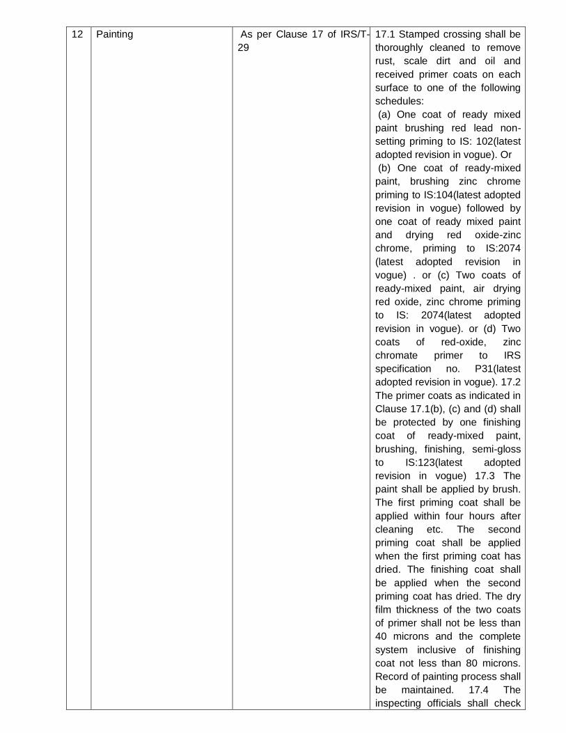
Annexure IV
M & C INSPECTION PROFORMA OF FITTING FOR CMS CROSSING
TYPE OF CMS CROSSING: ---------------------------------------------------------- AGAINST P.O. NO.—————————
—————— DATED——————— Quantity---------------------------------------
BOLT
NUT
C.I. CHECK RAIL BLOCK
ALT – 1 *
SPRING WASHER *
TAPER WASHER *
PACKING PIECE
*
BEARING
PLATE * C.I. DISTANCE BLOCK *
SPECIFICATI
ON
IRS/T-23 IRS/T-23 IS-210-93 FG 200 IRS/T-42 IS-2062-2011 Gr. E 250
BR
IS-2062-2011 Gr.
E 250 BR
IS-2062-2011 Gr.
E 250 BR
SPECIFIED ACT. SPECIFIED ACT. SPECIFIED ACT. SPECIFIED ACT. SPECIFIE
D
ACT.% SPE
CIFIE
D
ACT. SPECI
FIED
ACT.
UTS 55-68 NS - 20.4`
(Min)
NS - NS - NS - 410
MPA
min
YS - - - - 250
MPA
min
EL - - - - 23%
min
CHARPY - - - - -
BEND TEST No
crack
HARDNESS
NS NS - 160
220 BHN
-
43-49 HRC - NS - NS -
CHEMICAL
ANALYSIS
C=0.25-
0.35%
C=0.20-
0.30%
- C=0.50-0.60% - C=0.22%
max
- C=0.2
2%m
ax
- C=0.22
%max
Mn=0.6-
0.9%
Mn=0.6-
0.9%
- Mn=0.8-1.0% - Mn=1.5%
max
- Mn=1
.5%m
ax
- Mn=1.5
%max
P=0.04%ma
x
P=0.04%ma
x
- P=0.05%max - P=0.045%
max
- P=0.0
45%
max
- P=0.04
5%max
S=0.04%ma
x
S=0.04%ma
x
- S=0.05%max - S=0.045%
max
- S=0.0
45%
max
- S=0.04
5%max
Si=0.15-
0.35%
Si=0.15-
0.35%
- Si=1.5-2.0% - Si=0.4%m
ax
- Si=0.
4%m
ax
- Si=0.4
% max
UNSCREWIN
G
TEST
MAX 2KG TO
12KG
Screwing at
2 kg
unscrewing
at 12 kg
-
Screwing at
2 kg
unscrewing
at 12 kg
- NS - NS - NS - NS -
DIRIFT TEST no crack/
break -
no
crack/break - NS - NS - NS - NS -
TWIST TEST NS - NS - NS -
No
crack/break - NS - NS -
PERMANENT
SET TEST NS - NS - NS -
No
determation - NS - NS -
DEPTH OF
DECARBURI
SATION
NS - NS - NS - 0.10 mm
MAX - NS - NS -
HEAD
SOUNDNESS
TEST BEND
THROUGH
30(90-60)
No Crack at
300 bend - NS - NS - NS - NS - NS -

Appendix-II of IRS/T-29

Appendix-II of IRS/T-29 Contd..

APPENDIX-VI of IRS/T-29
PROFORMA FOR DIMENSIONAL INSPECTION OF CAST MANGANESE STEEL CROSSING
1 Cast on serial number
2 Type and section with drawing number
3 Date of inspection
4 Heat number
5 Items to be inspected 5.1 Positions of crossing (Running surface up) 5.1.1 End fitments (both toe and heel end) 5.1.2 Alignment at the fish-plated joint matching etc. 5.1.3 Length 5.1.4 Wheel tread 5.1.5 Top edge contour 5.1.6 Offset (both toe end and heel end) 5.1.7 Flange well depth (including surface condition of flange well) 5.1.8 Flange way clearance 5.1.9 Overall alignment (including local misalignment) 5.1.10 Throat clearance Top surface level 5.1.11 Top surface level 5.1.12 Concavity/convexity/twist. If any 5.1.13 Wing rails 5.1.14 Nose thickness. 5.1.15 Nose depression 5.1.16 Height at different locations 5.1.17 Fish bolt holes

5.1.18 Fishing plane 5.1.19 Bond holes
5.2 Position (Bottom up) 5.2.1 Bottom surface 5.2.2 Web thickness 5.2.3 Tie (thickness, width etc.) 5.2.4 Bottom width 5.2.5 Flange thickness (including thickness at recesss) 5.2.6 Roof thickness (i.e. below flange well, Vee portion etc.) 5.2.7 Condition of end section – faces (both heel and toe end) 5.3 Other items, if any
Manager (QC) of the Firm Inspecting official
Note: 1. Defect, if any, be marked on a sketch at appendix-IV 2. Marking of certain locations with chalk to
be done on the crossing as desired by inspecting official to expedite inspection with the help of
gauges/templates.
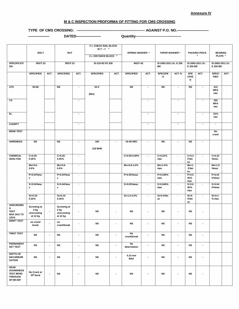
FINAL DIMENSIONAL INSPECTION SHEETFOR CMS CROSSING
Annexure -V
1 IN 16 CMS crossing to drg. no. RDSO/T-5693/1AGAINST ——RAILWAY P.O. NO.————————DATED——
Location Parameters Mode of measurements
Dimension as per drawing
Dimension observed during inspection
Top side of crossing
Sl. No. 1 2 3 4
S. No. of crossings
Date of cast
Total Length Tape 5400± 6
Top level Chord & filler gauge ± 1
Surface, radius & alignment Chord & filler gauge&
visual
± 1
Flange way clearance Gauge No.-2 63 +1,–0
Flange way cl. at throat Gauge No.-3 46.5 ± 1
Flange way cl. 41mm Gauge No.-4 41+1,–0
Nose depression Gauge No.-5 6 +2,–0
Nose thickness Gauge No.-6 16.5+1,–0
End slope Gauge No.-7 1 in 32
Wheel tread at TE Gauge No.-8 72 .0 ±1
Top edge contour. of wing (from inside) Gauge No.-9 R13 & 1:20 Slope
Top edge contour at 300mm from nose of
crossing
Gauge No.-10 R13 & 1:4 Slope
Top edge contour at heel end Gauge No.-12 R13, R80,R300& 1:20 Slope
Top edge contour (for vee portion) Gauge No.-11 R13 & 1:20 Slope
Wing rail (outside) Gauge No.-13 40 ±1, 1:20 Slope
Wing rail (at nose) Gauge No.-14 72±1, 1:20 Slope
Fishing plane cum bolt hole position Gauge No.-15 Ø27+0.8/-0, 95.5,27.25,41 &
1:2.75 Slope
Flange recess (at sleeper location) Gauge No.-16 11.5 ±0.5
Flange thickness for heel and toe end sleeper location-
Gauge No.-17 11.5 ±0.5, 180mm
Flange thickness at sleeper location other than
heel and toe end
Gauge No.-18 11.5 ±0.5
Plough share Gauge No.-19 102 ±1.0
Heel end offset Gauge No.-20 235±1.0
Tie/rib Gauge No.-21 250±03, 20 +3,–0
Flange thickness other than sleeper location Gauge No.-2) 20,23 +3,–0
Height at throat & at location with 1 in 20 inclination on to having 72mm head width
Gauge No.-23 174.9 +1.5,–0.5
Height for location without 1 in 20 inclination Gauge No.-24 172.0 +1.5,–0.5
Throat radius (inside) Gauge No.-25 R2750
Fish hole spacing (First sword Gauge) Gauge No.-26 83/166 ±0.6
Ø27 +0.8/-0,
Fish hole spacing (Second sword Gauge ) Gauge No.-27 166 .0 ±0.6
Fish bolt hole size Gauge No.-28 27 .0 +0.8,–0
checking of fish bolt holes with reference to machined bottom surface
Gauge No.-30 76.25 ±0.8 Ø27 +0.8/-0,
Casting Thickness (Web & Top Wall) Gauge No.-31,32 (25.0,30.0,40 .0 ) +5,-1
A.C/D.C bond hole Gauge No.-33 21.5 / 22.5 ±0.8
Flange Well depth at TE Gauge No.-34 52.0,77 +2,–0
Section at 100mm from ANC towards heel Gauge No.-35 1:20
Bottom side of
crossing
Surface & alignment Visual, chord & filler gauge
±1
Straightness & bend of crossing Gauge no.-29,36 ± 1
Sleeper spacing Gauge No.-35 600
Bottom width Gauge No.-1A 358.5 / 351.5 ±1
Bottom width Gauge No.-1B 344.5 / 337 ±1
Bottom width Gauge No.-1C 347.5/ 411 ±1
Bottom width Gauge No.-1D 474.5/295±1
Bottom width Gauge No.-1E 332.5 ±1
End
Fitment
Kink at fish plate joint Filler gauge. ±0.5
Gap between fish plate and casting Filler gauge 0.2mm filler should not pass
Quality Control Manager of M/s
Inspecting Official of QAC/RDSO

Annexure VI
CROSSING RDSO/T-5265/1 AGAINST ——RAILWAY P.O. NO.——————— DATED——————
Location Parameters Mode of
measurements
Dimension as per
drawing
Dimension observed during
inspection
Top Side
Of
Crossing
S. No. 1 2
LH RH LH RH
S. No. of crossings
Date of cast
Total Length 4200 ± 6
Top level ± 1
Surface, radius & alignment ± 1
Flange way clearance Gauge no.-2 70 ± 1
Flange way clearance Gauge no.-2A 104.5 ± 1
Flange way cl. At throat Gauge no.-3 50.5 ±1
Flange way cl. 41mm Gauge no.-4 41 + 1,-0
Flange way cl. 41mm at check rail side Gauge no.-4B 41 + 1,-0
Nose depression Gauge no.-5 6 +2,–0
Nose thickness Gauge no.-6 14 +1,–0
End slope Gauge no.-7 1 in 17 Slope
Wheel tread Gauge no.-8 67 .0 ±1
Top edge contour of wing (from inside) Gauge no.- 9 R13 & 1:20 Slope
Top edge contour at 399mm from nose of
crossing
Gauge no.-10 R13 & 1:4 Slope
Top edge contour at heel end Gauge no.-11 R13, R80 & R305
Top edge contour Gauge no.-12 R13& 1:20 Slope
Width of raised check rail (outside) Gauge no.-13 40 ±1 & 1:20 Slope
Width of elbow rail (at nose) Gauge no.-14 67±1 & 1:20 Slope
Fishing plane cum bolt hole position Gauge no.-15 Ø27+0.8/-0,
81.6,25.75,38.75&
1:2.75 Slope
Flange recess (at sleeper location) Gauge no.-16 9±0.5,1:6 Slope &180
Flange thickness for end sleeper location Gauge no.-17 9±0.5,1:6 Slope &
29.0
Flange thickness at sleeper location other
than end
Gauge no.-18 9±0.5,1:6 Slope &
40.0
Plough share gauge Gauge no.-19 179 ±1
End offset Gauge no.-20 313+1.5,–0
Thickness & width oftie/rib Gauge no.-21 250 ±3, 20 +3,-0
Flange thickness other than sleeper
location
Gauge no.-22 20 +3,–0
Height at throat & at location with 1 in 20
inclination on top (at raised check rail)
Gauge no.-23 181 +1.5,– 0.5
Height at throat & at location with 1 in 20
inclination on top having 67mm head width
Gauge no.-23A 158.7 +1.5,–0.5
Height for location without 1 in 20
inclination
Gauge no.-24 156 +1.5,–0.5
Throat radius (inside) Gauge no.-25 R2750
Fish hole spacing ( sword gauge) Gauge no.-26 166 / 83 ±0.6
Diameter of fish bolt hole Gauge no.-28 27 +0.8,–0
Gauge for checking fish bolt holes with
reference to machined bottom surface
Gauge no.-29 66.5 ±0.8
Ø27 +0.8/-0,
Casting Thickness Gauge no.-
30,31
22/ 25 +5,-1
Diameter of A.C/D.C bond hole Gauge no.-32 21.5 / 22.5 ±0.8
Well depth Gauge no.-33 48 +2,–0
Bottom
side of
crossing
Sleeper spacing Gauge no.-34 575
Straightness & bend of crossing Gauge no.-
28,35
± 1
Surface & alignment ±1
Bottom width Gauge no.-1A 293.5/348.5 ±1
Bottom width Gauge no.-1B 424/385.5 ±1
End
Fitment
Kink at fish plate joint Filler gauge ±0.5
Gap between fish plate and casting Filler gauge 0.2mm filler should not
pass
Quality Control Manager of M/s Inspecting Official of QAC/RDSO

Annexure-VII
1 IN 12 BG 60 KG TO RDSO DRAWING NO. RT-3940 / 1
….. RAILWAY P.O. NO. ………………………….……………………………………….. DATED: ……………..
Location Gauge Dimension as
per drawing Dimensions observed during inspection
S. No. 1 2 3 4 5 6 7 8 9 10
S. No. of crossings
Date of cast
Top side of
crossing
Total length 4350 ± 6
Top level ± 1
Surface, radius &
alignment ± 1
Flange way clearance 2 63 +1,–0
Flange way cl. At throat 3 63 ± 1
Flange way cl. 41mm 4 41 + 1,–0
Nose depression 5 6 + 2, –0
Nose thickness 6 16.5 +1, – 0
End slope 7 1 in 24
Wheel tread at TE 8 72 ± 1
Width of wing 13 40 ± 1
Width of wing rail 14 72 ± 1
Recess 16,17,18 11.5, 1 in 14 ±
0.5
Toe end offset 19 129 ± 1
Heel end offset 20 233 ± 1
Height with 1 in 20 slope 23 174.9 +1.5, – 0.5
Height without slope 24 172 +1.5, – 0.5
Radius Throat Gauge 25 R 2750
Pitch of holes 26 166 ± 0.6 ; 83 ±
0
Pitch of holes 27 166 ± 0.6
Bolt hole diameter 28 27 + 0.8, – 0
Bond hole diameter 33 21.5 / 22.5 +
0.8, – 0
Well depth at TE 34 52 +2, – 0
ANC 100mm 37
Bottom side
of crossing
Surface & alignment ± 1
Bottom width 1A 382.5/369.5 ± 1
Bottom width 1B 356.5/343.5 ± 1
Bottom width 1C 366.5/432.5 ± 1
Bottom width 1D 498/330.5 ± 1
End fitment Fitment at HE ± 0.5
Fitment at TE ± 0.5
Remark
Quality Control Manager of M/s
Inspecting Official of QAC/RDSO

Annexure-VIII 1 IN 12 BG 52 KG TO RDSO DRAWING NO. RT –4734/1 P.O. NO. : DATED :
Location Gauge
No.
Dimension as per
drawing Dimension observed during inspection
Sl. No. 1 2 3 4 5 6 7 8 9 10
Sl. No. of Crossing
Date of Cast
Top side of
crossing
Total Length 4350 + 6
Top Level + 1
Surface, radius & alignment + 1
Flange way clearance 2 63 + 1, -0
Flange way cl. At throat 3 63+ 1
Flange way cl. At Nose 4 41 + 1, -0
Nose depression 5 6 + 2, -0
Nose thickness 6 15.5 + 1, -0
End slope 7 1 in 24
Wheel tread at TE 8 67 + 1
Width of wing 13 40 + 1
Width of wing rail 14 67 + 1
Recess 16, 17,
18 9, 1 in 6 + 0.5
Toe end offset 19 129 + 1
Heel end offset 20 233 + 1
Height with 1 in 20 slope 23 158.7 + 1.5,-0.5
Height without slope 24 156 + 1.5, -0.5
Pitch of holes 26 166 + 0.6 ; 83 + 0
Pitch of holes 27 166 + 0.6
Bolt hole diameter 28 27 + 0.8, -0
Bond hole diameter 33 21.5/22.5 + 0.8, -0
Well depth at TE 34 48+ 2, -0
Section from 100mm 37 ---
Bottom
side of
crossing
Surface & alignment + 1
Bottom width 1A 382.5/369.5 + 1
Bottom width 1B 356.5/343.5 + 1
Bottom width 1C 366.5/432.5 + 1
Bottom width 1D 498/330.5 + 1
End fitment Fitment at HE + 0.5
Fitment at TE + 0.5
Gauge No. 25 ---
Remarks Satisfactory
Quality Control Manager
of M/s
Inspecting Official of QAC/RDSO
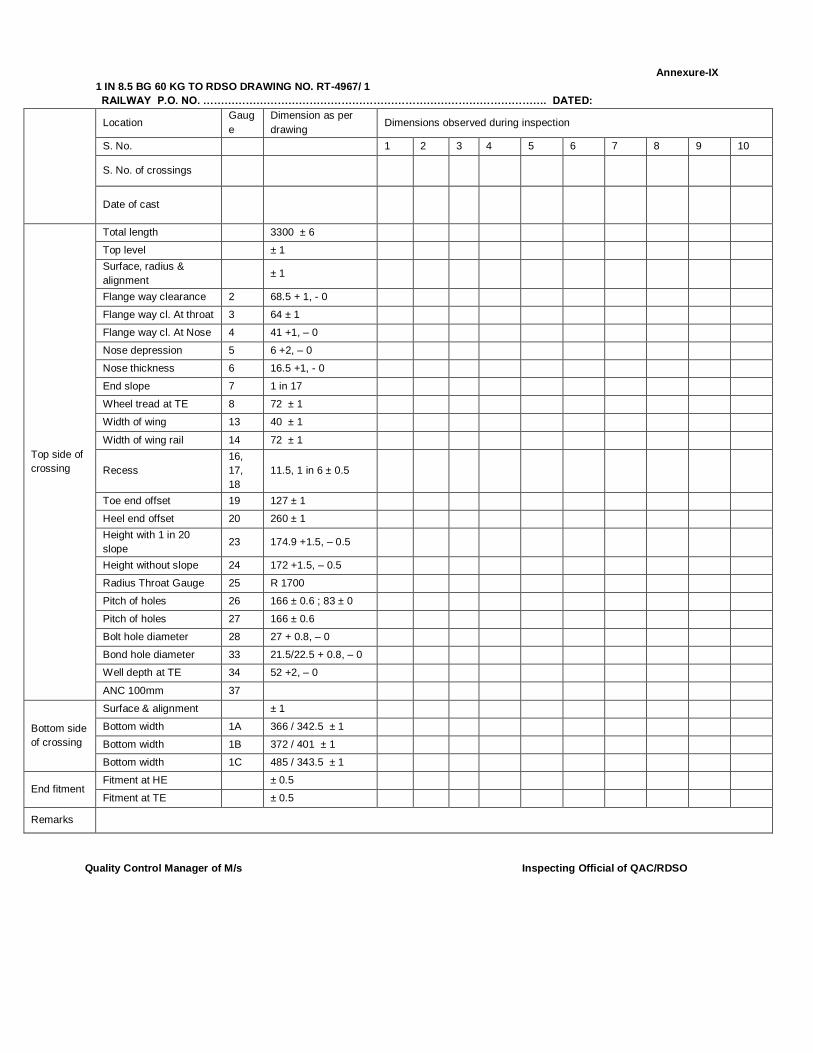
Annexure-IX
1 IN 8.5 BG 60 KG TO RDSO DRAWING NO. RT-4967/ 1
RAILWAY P.O. NO. ……………………………………………………………………………………. DATED:
Location Gaug
e
Dimension as per
drawing Dimensions observed during inspection
S. No. 1 2 3 4 5 6 7 8 9 10
S. No. of crossings
Date of cast
Top side of
crossing
Total length 3300 ± 6
Top level ± 1
Surface, radius &
alignment ± 1
Flange way clearance 2 68.5 + 1, - 0
Flange way cl. At throat 3 64 ± 1
Flange way cl. At Nose 4 41 +1, – 0
Nose depression 5 6 +2, – 0
Nose thickness 6 16.5 +1, - 0
End slope 7 1 in 17
Wheel tread at TE 8 72 ± 1
Width of wing 13 40 ± 1
Width of wing rail 14 72 ± 1
Recess
16,
17,
18
11.5, 1 in 6 ± 0.5
Toe end offset 19 127 ± 1
Heel end offset 20 260 ± 1
Height with 1 in 20
slope 23 174.9 +1.5, – 0.5
Height without slope 24 172 +1.5, – 0.5
Radius Throat Gauge 25 R 1700
Pitch of holes 26 166 ± 0.6 ; 83 ± 0
Pitch of holes 27 166 ± 0.6
Bolt hole diameter 28 27 + 0.8, – 0
Bond hole diameter 33 21.5/22.5 + 0.8, – 0
Well depth at TE 34 52 +2, – 0
ANC 100mm 37
Bottom side
of crossing
Surface & alignment ± 1
Bottom width 1A 366 / 342.5 ± 1
Bottom width 1B 372 / 401 ± 1
Bottom width 1C 485 / 343.5 ± 1
End fitment Fitment at HE ± 0.5
Fitment at TE ± 0.5
Remarks
Quality Control Manager of M/s
Inspecting Official of QAC/RDSO

Annexure-X
1 IN 8.5 BG 52 KG TO RDSO DRAWING NO. RT- 4867/2
….……. RAILWAY P.O. NO. ………………………………………… DATED: ………………..
Location Gauge Dimension as
per drawing Dimensions observed during inspection
S. No. 1 2 3 4 5 6 7 8 9 10
S. No. of crossings
Date of cast
Top side
of
crossing
Total length 3300 ± 6
Top level ± 1
Surface, radius &
alignment ± 1
Flange way clearance 2 68.5 + 1, - 0
Flange way cl. At throat 3 64 ± 1
Flange way cl. At Nose 4 41 +1, – 0
Nose depression 5 6 +2, – 0
Nose thickness 6 15.5 +1, - 0
End slope 7 1 in 17
Wheel tread at TE 8 67 ± 1
Width of wing 13 40 ± 1
Width of wing rail 14 67 ± 1
Recess 16, 17,
18 9, 1 in 6 ± 0.5
Toe end offset 19 127 ± 1
Heel end offset 20 260 ± 1
Height with 1 in 20 slope 23 158.7 +1.5, –
0.5
Height without slope 24 156 +1.5, –
0.5
Radius Throat Gauge 25 R 1700
Pitch of holes 26 166 ± 0.6 ; 83
± 0
Pitch of holes 27 166 ± 0.6
Bolt hole diameter 28 27 + 0.8, – 0
Bond hole diameter 33 21.5/22.5 +
0.8, – 0
Well depth at TE 34 48 +2, – 0
ANC 100mm 37 --
Bottom
side of
crossing
Surface & alignment ± 1
Bottom width 1A 366 / 342.5 ±
1
Bottom width 1B 372 / 401 ± 1
Bottom width 1C 485 / 343.5 ±
1
End
fitment
Fitment at HE ± 0.5
Fitment at TE ± 0.5
Remarks
Quality Control Manager
of M/s
Inspecting Official of QAC/RDSO
INSPECTION CHECK SHEET
FOR CMS Crossing-1

INSPECTION CHECK SHEET FOR CMS Crossing-1
NAME OF FIRM
PURCHASER RAILWAY
QUANTITY
CALL LETTER NUMBER
CONTRACT DETAILS
S.N. Reference Item
1 Whether Original Copy of Purchase Order available? Yes/No
2 Whether delivery period available? Yes/No 3 Whether consignee details available? Yes/No
INSPECTION GAUGES
4 Whether working gauges approved by RDSO is available? Yes/No
5 Whether approval certificate for inspection gauges issued by RDSO
is available and valid?
Yes/No
QUALITY ASSURANCE PLAN
6 Whether approved copy of Quality Assurance Programme
(QAP) is available?
Yes/No
7 Whether Firm is following approved QAP (To be verified
from the records)?
Yes/No
8 Whether firm is approved or development vendor? Yes/No
AVAILABILITY OF DRAWING & SPECIFICATION
9 Whether all the relevant drawings are available? Yes/No
10 Whether all BIS code and IRS specification mentioned in IRS Specification. For Cast Manganese Steel Crossings Serial No. IRST:T 29 2016 and QAP
are available?
Yes/No
PROCESS
11 Para 2 of IRS:T 29 2016 Whether QAP issued RDSO is followed? Yes/No
PLANT, MACHINERY & TESTING INSTRUMENT
12 Para 1.3 of IRS:T 29 2016 Whether firm have valid Class “A” foundries certificate
issued by RDSO?
Yes/No
TESTING
13 Internal test report Whether internal test report is having all the details and is
satisfactory?
Yes/No
14 Display Whether testing procedure has been displayed at every
test instrument?
Yes/No
15 Calibration Whether machines/equipments used in testing and
production is calibrated as per IRS:T 29 2016 and QAP?
Yes/No

16 Para 4 of IRS:T 29 2016. Whether chemical analyzed as per relevant parts of
IS:12308 and have following composition?
Carbon 1.0 to1.4%
Silicon(Max) 0.5%
Manganese 11 to14%
Sulphur(Max) 0.03%
Phosphrous 0.06%
Yes/No
17 Para 4 of IRS:T 29 2016. Whether ratio of Manganese to carbon as per IRS:T 29 2016?.
Yes/No
18 Para 4.3 of IRS:T 29 2016. Whether calibration of spectrometer used in testing is calibrated?
Yes/No
19 Para 6.2.1 of IRS:T 29 2016. Whether Surface inspection of crossing is inspected as per Para 6.2.1 of IRS:T 29 2016?
Yes/No
20 Para 6.2.2 of IRS:T 29 2016. Whether Frequency of solidity test carried out after clearance of prototype is three years or completion of manufacturing of 1000CMS crossings? which is earlier.
Yes/No
21 Para 7 of IRS:T 29 2016. Whether four number of test bars of size 200 mm X 30 mm X 30 mm (with tolerance of ± 1 mm in each dimension) is casted integral to crossing and located at toe end and heel end respectively (2 number each)?
Yes/No
22 Para 7.3 of IRS:T 29 2016. Whether Integral test bar casted such that it should not get detached during knock out, fettling, shot blasting or heat treatment?
Yes/No
23 Para 7.4 of IRS:T 29 2016. Whether these integral bar be used for chemical composition, microstructure / grain size determination, hardness and for impact bend test ?
Yes/No
24 Para 7.5 of IRS:T 29 2016. Whether Integral test bar detached from crossing by suitable method to avoid any damage to crossing?
Yes/No
25 Para 7.5 of IRS:T 29 2016. Whether detachment of Integral bar be done in the presence of inspecting official?
Yes/No
26 Para 7.6 of IRS:T 29 2016. Whether identification is given to Intergral bar in terms of crossing number and location?
Yes/No
27 Para 7.6 of IRS:T 29 2016. Whether integral test bar is preserved? (at least one integral test bar of each crossing for minimum 6 months from the date of issue of inspection certificate of particular crossing and shall present to inspecting official on demand)
Yes/No
28 Para 8.2 of IRS:T 29 2016. Whether marking is done as para 8.2 of IRS:T 29 2016? Yes/No
29 Para 8.4 of IRS:T 29 2016. Whether pouring is done as para 8.4 of IRS:T 29 2016? ( Once in six month)
Yes/No
30 Para 8.7 of IRS:T 29 2016. Whether Heat Treatment of crossings is done as para 8.7of IRS: T 29 2016?
Yes/No
31 Para 8.8 of IRS: T 29 2016. Whether surface preparation of crossings is done as para 8.8 of IRS: T 29 2016?
Yes/No
32 Para 8.9 of IRS: T 29 2016. Whether Straightening of crossings is done as para 8.9 of IRS:T 29 2016?
Yes/No
33 Para 10.4.1 of IRS: T 29 2016. Whether pouring is witnessed by inspecting official at least once every six month?
Yes/No
34 Para 10.4.3.4 of IRS:T 29 2016. Whether micro test piece cut from the integral test bar duly heat treated along with CMS crossing?
Yes/No
35 Para 10.4.3.4 of IRS:T 29 2016. Whether determination of grain size and microstructure is done as per para 13.4.?
Yes/No

36 Para 10.4.3.4 of IRS:T 29 2016. Whether gross dimension of CMS crossing is measured as per Para 10.4.3.4 of IRS:T 29 2016 and recorded in inspection memo-IV as appendix-II?
Yes/No
37 Para 10.4.4 of IRS:T 29 2016. Whether gross dimension of CMS crossing is measured as per Para 10.4.3.4 of IRS:T 29 2016 and recorded in inspection memo-IV as appendix-II?
Yes/No
38 Para 10.4.4 of IRS:T 29 2016. If case of any defect, whether for rectification par 10.4.4.1, 10.4.4.2,10.4.4.3 of IRS:T 29 2016 is followed?
Yes/No
39 Para 13.1 of IRS:T 29 2016. Whether Impact Bend test on crossings & test bar is done as para 8.7of IRS:T 29 2016? Note:-The test Piece must withstand three Impact & crack must not extend more than 7mm up
Yes/No
40 Para 13.2 of IRS:T 29 2016. Whether Hardness test on crossings & test bar is done as para 8.7of IRS:T 29 2016?
Note
Hardness on CMS crossing (BHN)
Hardness on Test Bar (BHN)
In Thick section ( BHN< 229 or equivalent)
Test Bar pick from Heel end from one crossing ( BHN< 229 or equivalent)
In Thin Section ( BHN< 229 or equivalent)
Test Bar pick from Toe end from preferably another crossing
( BHN< 229 or equivalent)
Yes/No
41 Para 13.4.1 of IRS:T 29 2016. Whether testing of grain size and microstructure of crossings and bar is done as para 8.7of IRS:T 29 2016? Note:- 1.ASTM Grain Size (ASTM Grain size should be 4 or finer) 2.Structure (should be Single phase Austenite ,free from carbide precipitation)
Yes/No
42 Para 13.4.1 of IRS:T 29 2016. Whether testing of grain size and microstructure of crossings and bar is done as para 8.7of IRS:T 29 2016?
Note:- 1.ASTM Grain Size (ASTM Grain size should be 4 or finer)
2.Structure (should be Single phase Austenite ,free from carbide precipitation)
Yes/No
Test on fittings
43 Bolts and Nuts Whether chemical, physical and metallurgical test on bolts and done as per IRST-23 and desired value required in QAP?
Yes/No
44 C.I check rail block and C.I distance block
Whether chemical, physical and metallurgical test on bolts and done as per IS-210-93 FG 200 and desired value required in QAP?
Yes/No
45 Spring washer
Whether chemical, physical and metallurgical test on bolts and done as per IRS/T-42 and desired value required in QAP?
Yes/No
46 Taper washer, Packing piece , Bearing plate
Whether chemical, physical and metallurgical test on bolts and done as per IS-2062-2011 Gr. E 250 BR and desired value required in QAP?
Yes/No
48 Rejection As per Para 14 of IRS:T 29 2016
Whether disposal of rejected crossing is done as per laid procedure?
Yes/No
49 Whether disposal of rejected fitting is done as per relevant IRS & QAP procedure?
Yes/No

INSPECTION CHECK SHEET
FOR CMS Crossing-2

INSPECTION CHECK SHEET FOR CMS Crossing -2
NAME OF FIRM
PURCHASER RAILWAY
QUANTITY
CALL LETTER NUMBER
CONTRACT DETAILS
S.N. Reference Item Yes/No
1 Whether Original Copy of Purchase Order available?
2 Whether delivery period available? 3 Whether consignee details available?
INSPECTION GAUGES
S.N. Reference Item Yes/No
4 Para 10.4.5.1 of IRS:T 29 2016
Whether working gauges approved by RDSO is available?
5 Para 10.4.5.1 of IRS:T 29 2016 Whether approval certificate for inspection gauges issued by RDSO
is available and valid?
QUALITY ASSURANCE PLAN
S.N. Reference Item Yes/No
6 Whether approved copy of Quality Assurance Programme
(QAP) is available?
7 Whether Firm is following approved QAP (To be verified
from the records)?
8 Whether firm is approved or development vendor?
AVAILABILITY OF DRAWING & SPECIFICATION
S.N. Reference Item Yes/No
9 Whether all the relevant drawings are available?
10 Whether all BIS code and IRS specification mentioned in IRS Specification. For Cast Manganese Steel Crossings Serial No. IRST:T 29 2016 and QAP are available?
PROCESS
S.N. Reference Item Yes/No
11 Para 2 of IRS:T 29 2016 Whether QAP issued RDSO is followed?
PLANT, MACHINERY & TESTING INSTRUMENT
12 Para 1.3 of IRS:T 29 2016 Whether firm have valid Class A foundries certificate
issued by RDSO?
Yes/No
TESTING
13 Whether Appendix-II upto inspection Memo-V (with
satisfactory report) is dully signed by firm’s representative
and inspecting official (M&C) ?
Yes/No
14 Internal test report Whether internal test report is having all the details and is
satisfactory?
Yes/No
15 Display Whether testing procedure has been displayed at every
test instrument?
Yes/No
16 Calibriation Whether machines / equipments used in testing and
production is calibrated as per IRS:T 29 2016 and QAP?
Yes/No
17 Para 6.2.3 of IRS:T 29 2016. Whether Radiographic examination shall be done at the rate of 1 in 10 for regular manufacture and 1 in 5 for prototype castings subject to a minimum of one
Casting of each type?
Yes/No
18 Para 8.9 of IRS:T 29 2016. Whether Straightening of crossings is done as para 8.9 of IRS:T 29 2016?
Yes/No
19 Para 8.10 of IRS:T 29 2016. Whether finishing of crossings is done as para 8.9 of IRS:T 29 2016?
Yes/No
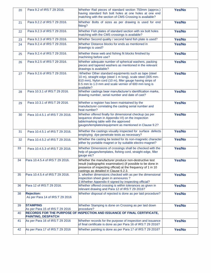
20 Para 9.2 of IRS:T 29 2016. Whether Rail pieces of standard section 750mm (approx.) having standard fish bolt holes at one holes at one end matching with the section of CMS Crossing is available?
Yes/No
21 Para 9.2.2 of IRS:T 29 2016. Whether Bolts of sizes as per drawing is used for end fitting?
Yes/No
22 Para 9.2.3 of IRS:T 29 2016. Whether Fish plates of standard section with six bolt holes matching with the CMS crossings is available?
Yes/No
23 Para 9.2.3 of IRS:T 29 2016. Whether Second quality / second hand fish plate is used? Yes/No
24 Para 9.2.4 of IRS:T 29 2016. Whether Distance blocks for ends as mentioned in drawings is used?
Yes/No
25 Para 9.2.4 of IRS:T 29 2016. Whether these web and fishing fit blocks finished by machining before use?
Yes/No
26 Para 9.2.5 of IRS:T 29 2016. Whether adequate number of spherical washers, packing pieces and tapered washers as mentioned in the relevant drawings is available?
Yes/No
27 Para 9.2.6 of IRS:T 29 2016. Whether Other standard equipments such as tape (steel 10 m), straight edge (steel 1 m long), scale steel (305 mm-610 mm), Nylon cord (10 m), filler gauge having strips of 0.5 mm to 1.0 mm and scale vernier of 600 mm long is available?
Yes/No
28 Para 10.3.1 of IRS:T 29 2016. Whether castings bear manufacturer’s identification marks, drawing number, serial number and date of cast?
Yes/No
29 Para 10.3.1 of IRS:T 29 2016. Whether a register has been maintained by the manufacturer correlating the casting serial number and heat number?
Yes/No
30 Para 10.4.5.1 of IRS:T 29 2016. Whether offered finally for dimensional checkup (as per sequence shown in Appendix-VI) on the inspection table/marking table with the approved gauges/templates/equipment as mentioned in Clause 9.2?
Yes/No
31 Para 10.4.5.1 of IRS:T 29 2016. Whether the castings visually inspected for surface defects employing dye-penetrate tests as necessary?
Yes/No
32 Para 10.4.5.2 of IRS:T 29 2016. Whether the casting be tested for its non-magnetic character either by portable magnet or by suitable electro-magnet?
Yes/No
33 Para 10.4.5.3 of IRS:T 29 2016. Whether Dimensions of crossings shall be checked with the help of gauges/templates, fishing cord, straight edge, filler gauge etc?
Yes/No
34 Para 10.4.5.4 of IRS:T 29 2016. Whether the manufacturer produce non-destructive test result (radiographic examination) (if possible to be done in presence of inspecting official) at the frequency of 1 in 10 castings as detailed in Clause 6.2.3.
Yes/No
35 Para 10.4.5.4 of IRS:T 29 2016. 1. whether dimensions checked with as per the dimensional inspection sheet given in annexures ? 2.Whether Appendix-II signed by inspecting official?
Yes/No
36 Para 12 of IRS:T 29 2016. Whether offered crossing is within tolerances as given in relevant drawing and Para 12 of IRS:T 29 2016?
Yes/No
38 Rejection:
As per Para 14 of IRS:T 29 2016 Whether disposal of rejected is done as per laid procedure? Yes/No
39 STAMPING
As per Para 15 of IRS:T 29 2016 Whether Stamping is done on Crossing as per laid down procedure?
Yes/No
40 RECORDS FOR THE PURPOSE OF INSPECTION AND ISSUANCE OF FINAL CERTIFICATE, PAINTING, DESPATCH
41 As per Para 16 of IRS:T 29 2016 Whether records for the purpose of inspection and issuance of final certificate is done as per Para 16 of IRS:T 29 2016?
Yes/No
42 As per Para 17 of IRS:T 29 2016 Whether painting is done as per Para 17 of IRS:T 29 2016? Yes/No
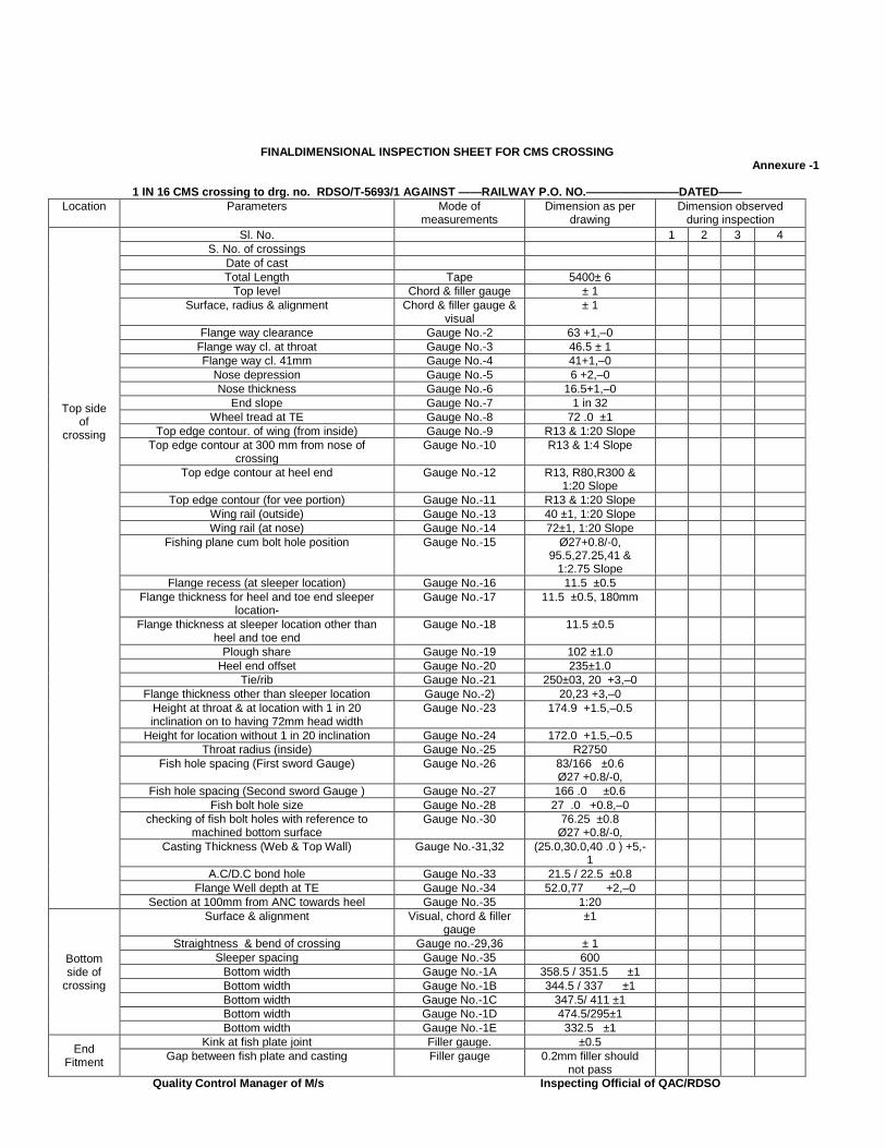
FINALDIMENSIONAL INSPECTION SHEET FOR CMS CROSSING Annexure -1
1 IN 16 CMS crossing to drg. no. RDSO/T-5693/1 AGAINST ——RAILWAY P.O. NO.————————DATED——
Location Parameters Mode of measurements
Dimension as per drawing
Dimension observed during inspection
Top side of
crossing
Sl. No. 1 2 3 4
S. No. of crossings
Date of cast
Total Length Tape 5400± 6
Top level Chord & filler gauge ± 1
Surface, radius & alignment Chord & filler gauge & visual
± 1
Flange way clearance Gauge No.-2 63 +1,–0
Flange way cl. at throat Gauge No.-3 46.5 ± 1
Flange way cl. 41mm Gauge No.-4 41+1,–0
Nose depression Gauge No.-5 6 +2,–0
Nose thickness Gauge No.-6 16.5+1,–0
End slope Gauge No.-7 1 in 32
Wheel tread at TE Gauge No.-8 72 .0 ±1
Top edge contour. of wing (from inside) Gauge No.-9 R13 & 1:20 Slope
Top edge contour at 300 mm from nose of crossing
Gauge No.-10 R13 & 1:4 Slope
Top edge contour at heel end Gauge No.-12 R13, R80,R300 & 1:20 Slope
Top edge contour (for vee portion) Gauge No.-11 R13 & 1:20 Slope
Wing rail (outside) Gauge No.-13 40 ±1, 1:20 Slope
Wing rail (at nose) Gauge No.-14 72±1, 1:20 Slope
Fishing plane cum bolt hole position Gauge No.-15 Ø27+0.8/-0, 95.5,27.25,41 &
1:2.75 Slope
Flange recess (at sleeper location) Gauge No.-16 11.5 ±0.5
Flange thickness for heel and toe end sleeper location-
Gauge No.-17 11.5 ±0.5, 180mm
Flange thickness at sleeper location other than heel and toe end
Gauge No.-18 11.5 ±0.5
Plough share Gauge No.-19 102 ±1.0
Heel end offset Gauge No.-20 235±1.0
Tie/rib Gauge No.-21 250±03, 20 +3,–0
Flange thickness other than sleeper location Gauge No.-2) 20,23 +3,–0
Height at throat & at location with 1 in 20 inclination on to having 72mm head width
Gauge No.-23 174.9 +1.5,–0.5
Height for location without 1 in 20 inclination Gauge No.-24 172.0 +1.5,–0.5
Throat radius (inside) Gauge No.-25 R2750
Fish hole spacing (First sword Gauge) Gauge No.-26 83/166 ±0.6 Ø27 +0.8/-0,
Fish hole spacing (Second sword Gauge ) Gauge No.-27 166 .0 ±0.6
Fish bolt hole size Gauge No.-28 27 .0 +0.8,–0
checking of fish bolt holes with reference to machined bottom surface
Gauge No.-30 76.25 ±0.8 Ø27 +0.8/-0,
Casting Thickness (Web & Top Wall) Gauge No.-31,32 (25.0,30.0,40 .0 ) +5,-1
A.C/D.C bond hole Gauge No.-33 21.5 / 22.5 ±0.8
Flange Well depth at TE Gauge No.-34 52.0,77 +2,–0
Section at 100mm from ANC towards heel Gauge No.-35 1:20
Bottom side of
crossing
Surface & alignment Visual, chord & filler gauge
±1
Straightness & bend of crossing Gauge no.-29,36 ± 1
Sleeper spacing Gauge No.-35 600
Bottom width Gauge No.-1A 358.5 / 351.5 ±1
Bottom width Gauge No.-1B 344.5 / 337 ±1
Bottom width Gauge No.-1C 347.5/ 411 ±1
Bottom width Gauge No.-1D 474.5/295±1
Bottom width Gauge No.-1E 332.5 ±1
End Fitment
Kink at fish plate joint Filler gauge. ±0.5
Gap between fish plate and casting Filler gauge 0.2mm filler should not pass
Quality Control Manager of M/s
Inspecting Official of QAC/RDSO

Annexure 2 CROSSING RDSO/T-5265/1 AGAINST ——RAILWAY P.O. NO.——————— DATED——————
Location Parameters Mode of measurements
Dimension as per drawing
Dimension observed during inspection
Top Side Of
Crossing
S. No. 1 2
LH RH LH RH
S. No. of crossings
Date of cast
Total Length 4200 ± 6
Top level ± 1
Surface, radius & alignment ± 1
Flange way clearance Gauge no.-2 70 ± 1
Flange way clearance Gauge no.-2A 104.5 ± 1
Flange way cl. At throat Gauge no.-3 50.5 ±1
Flange way cl. 41mm Gauge no.-4 41 + 1,-0
Flange way cl. 41mm at check rail side Gauge no.-4B 41 + 1,-0
Nose depression Gauge no.-5 6 +2,–0
Nose thickness Gauge no.-6 14 +1,–0
End slope Gauge no.-7 1 in 17 Slope
Wheel tread Gauge no.-8 67 .0 ±1
Top edge contour of wing (from inside) Gauge no.- 9 R13 & 1:20 Slope
Top edge contour at 399mm from nose of crossing
Gauge no.-10 R13 & 1:4 Slope
Top edge contour at heel end Gauge no.-11 R13, R80 & R305
Top edge contour Gauge no.-12 R13& 1:20 Slope
Width of raised check rail (outside) Gauge no.-13 40 ±1 & 1:20 Slope
Width of elbow rail (at nose) Gauge no.-14 67±1 & 1:20 Slope
Fishing plane cum bolt hole position Gauge no.-15 Ø27+0.8/-0, 81.6,25.75,38.75&
1:2.75 Slope
Flange recess (at sleeper location) Gauge no.-16 9±0.5,1:6 Slope &180
Flange thickness for end sleeper location Gauge no.-17 9±0.5,1:6 Slope & 29.0
Flange thickness at sleeper location other than end
Gauge no.-18 9±0.5,1:6 Slope & 40.0
Plough share gauge Gauge no.-19 179 ±1
End offset Gauge no.-20 313+1.5,–0
Thickness & width oftie/rib Gauge no.-21 250 ±3, 20 +3,-0
Flange thickness other than sleeper location
Gauge no.-22 20 +3,–0
Height at throat & at location with 1 in 20 inclination on top (at raised check rail)
Gauge no.-23 181 +1.5,– 0.5
Height at throat & at location with 1 in 20 inclination on top having 67mm head width
Gauge no.-23A 158.7 +1.5,–0.5
Height for location without 1 in 20 inclination
Gauge no.-24 156 +1.5,–0.5
Throat radius (inside) Gauge no.-25 R2750
Fish hole spacing ( sword gauge) Gauge no.-26 166 / 83 ±0.6
Diameter of fish bolt hole Gauge no.-28 27 +0.8,–0
Gauge for checking fish bolt holes with reference to machined bottom surface
Gauge no.-29 66.5 ±0.8 Ø27 +0.8/-0,
Casting Thickness Gauge no.-30,31
22/ 25 +5,-1
Diameter of A.C/D.C bond hole Gauge no.-32 21.5 / 22.5 ±0.8
Well depth Gauge no.-33 48 +2,–0
Bottom side of
crossing
Sleeper spacing Gauge no.-34 575
Straightness & bend of crossing Gauge no.-28,35
± 1
Surface & alignment ±1
Bottom width Gauge no.-1A 293.5/348.5 ±1
Bottom width Gauge no.-1B 424/385.5 ±1
End Fitment
Kink at fish plate joint Filler gauge ±0.5
Gap between fish plate and casting Filler gauge 0.2mm filler should not pass
Quality Control Manager
of M/s Inspecting Official of QAC/RDSO

Annexure-3 1 IN 12 BG 60 KG TO RDSO DRAWING NO. RT-3940 / 1
….. RAILWAY P.O. NO. ………………………….……………………………………….. DATED: ……………..
Location Gauge Dimension as per drawing
Dimensions observed during inspection
S. No. 1 2 3 4 5 6 7 8 9 10
S. No. of crossings
Date of cast
Top side of crossing
Total length 4350 ± 6
Top level ± 1
Surface, radius & alignment
± 1
Flange way clearance 2 63 +1,–0
Flange way cl. At throat 3 63 ± 1
Flange way cl. 41mm 4 41 + 1,–0
Nose depression 5 6 + 2, –0
Nose thickness 6 16.5 +1, – 0
End slope 7 1 in 24
Wheel tread at TE 8 72 ± 1
Width of wing 13 40 ± 1
Width of wing rail 14 72 ± 1
Recess 16,17,18 11.5, 1 in 14 ±
0.5
Toe end offset 19 129 ± 1
Heel end offset 20 233 ± 1
Height with 1 in 20 slope 23 174.9 +1.5, – 0.5
Height without slope 24 172 +1.5, – 0.5
Radius Throat Gauge 25 R 2750
Pitch of holes 26 166 ± 0.6 ; 83 ±
0
Pitch of holes 27 166 ± 0.6
Bolt hole diameter 28 27 + 0.8, – 0
Bond hole diameter 33 21.5 / 22.5 +
0.8, – 0
Well depth at TE 34 52 +2, – 0
ANC 100mm 37
Bottom side of crossing
Surface & alignment ± 1
Bottom width 1A 382.5/369.5 ± 1
Bottom width 1B 356.5/343.5 ± 1
Bottom width 1C 366.5/432.5 ± 1
Bottom width 1D 498/330.5 ± 1
End fitment Fitment at HE ± 0.5
Fitment at TE ± 0.5
Remark
Quality Control Manager of M/s
Inspecting Official of QAC/RDSO

Annexure-4 1 IN 12 BG 52 KG TO RDSO DRAWING NO. RT –4734/1 P.O. NO. : DATED :
Location Gauge
No. Dimension as per
drawing Dimension observed during inspection
Sl. No. 1 2 3 4 5 6 7 8 9 10
Sl. No. of Crossing
Date of Cast
Top side of crossing
Total Length 4350 + 6
Top Level + 1
Surface, radius & alignment + 1
Flange way clearance 2 63 + 1, -0
Flange way cl. At throat 3 63+ 1
Flange way cl. At Nose 4 41 + 1, -0
Nose depression 5 6 + 2, -0
Nose thickness 6 15.5 + 1, -0
End slope 7 1 in 24
Wheel tread at TE 8 67 + 1
Width of wing 13 40 + 1
Width of wing rail 14 67 + 1
Recess 16, 17,
18 9, 1 in 6 + 0.5
Toe end offset 19 129 + 1
Heel end offset 20 233 + 1
Height with 1 in 20 slope 23 158.7 + 1.5,-0.5
Height without slope 24 156 + 1.5, -0.5
Pitch of holes 26 166 + 0.6 ; 83 + 0
Pitch of holes 27 166 + 0.6
Bolt hole diameter 28 27 + 0.8, -0
Bond hole diameter 33 21.5/22.5 + 0.8, -0
Well depth at TE 34 48+ 2, -0
Section from 100mm 37 ---
Bottom side of
crossing
Surface & alignment + 1
Bottom width 1A 382.5/369.5 + 1
Bottom width 1B 356.5/343.5 + 1
Bottom width 1C 366.5/432.5 + 1
Bottom width 1D 498/330.5 + 1
End fitment Fitment at HE + 0.5
Fitment at TE + 0.5
Gauge No. 25 ---
Remarks Satisfactory
Quality Control Manager of M/s
Inspecting Official of QAC/RDSO

Annexure-5 1 IN 8.5 BG 60 KG TO RDSO DRAWING NO. RT-4967/ 1
RAILWAY P.O. NO. ……………………………………………………………………………………. DATED:
Location Gaug
e Dimension as per
drawing Dimensions observed during inspection
S. No. 1 2 3 4 5 6 7 8 9 10
S. No. of crossings
Date of cast
Top side of crossing
Total length 3300 ± 6
Top level ± 1
Surface, radius & alignment
± 1
Flange way clearance 2 68.5 + 1, - 0
Flange way cl. At throat 3 64 ± 1
Flange way cl. At Nose 4 41 +1, – 0
Nose depression 5 6 +2, – 0
Nose thickness 6 16.5 +1, - 0
End slope 7 1 in 17
Wheel tread at TE 8 72 ± 1
Width of wing 13 40 ± 1
Width of wing rail 14 72 ± 1
Recess 16, 17, 18
11.5, 1 in 6 ± 0.5
Toe end offset 19 127 ± 1
Heel end offset 20 260 ± 1
Height with 1 in 20 slope
23 174.9 +1.5, – 0.5
Height without slope 24 172 +1.5, – 0.5
Radius Throat Gauge 25 R 1700
Pitch of holes 26 166 ± 0.6 ; 83 ± 0
Pitch of holes 27 166 ± 0.6
Bolt hole diameter 28 27 + 0.8, – 0
Bond hole diameter 33 21.5/22.5 + 0.8, – 0
Well depth at TE 34 52 +2, – 0
ANC 100mm 37
Bottom side of crossing
Surface & alignment ± 1
Bottom width 1A 366 / 342.5 ± 1
Bottom width 1B 372 / 401 ± 1
Bottom width 1C 485 / 343.5 ± 1
End fitment Fitment at HE ± 0.5
Fitment at TE ± 0.5
Remarks
Quality Control Manager of M/s
Inspecting Official of QAC/RDSO

Annexure-6
1 IN 8.5 BG 52 KG TO RDSO DRAWING NO. RT- 4867/2 ….……. RAILWAY P.O. NO. ………………………………………… DATED: ………………..
Location Gauge Dimension as per drawing
Dimensions observed during inspection
S. No. 1 2 3 4 5 6 7 8 9 10
S. No. of crossings
Date of cast
Top side of
crossing
Total length 3300 ± 6
Top level ± 1
Surface, radius & alignment
± 1
Flange way clearance 2 68.5 + 1, - 0
Flange way cl. At throat 3 64 ± 1
Flange way cl. At Nose 4 41 +1, – 0
Nose depression 5 6 +2, – 0
Nose thickness 6 15.5 +1, - 0
End slope 7 1 in 17
Wheel tread at TE 8 67 ± 1
Width of wing 13 40 ± 1
Width of wing rail 14 67 ± 1
Recess 16, 17,
18 9, 1 in 6 ± 0.5
Toe end offset 19 127 ± 1
Heel end offset 20 260 ± 1
Height with 1 in 20 slope 23 158.7 +1.5, –
0.5
Height without slope 24 156 +1.5, –
0.5
Radius Throat Gauge 25 R 1700
Pitch of holes 26 166 ± 0.6 ; 83
± 0
Pitch of holes 27 166 ± 0.6
Bolt hole diameter 28 27 + 0.8, – 0
Bond hole diameter 33 21.5/22.5 +
0.8, – 0
Well depth at TE 34 48 +2, – 0
ANC 100mm 37 --
Bottom side of
crossing
Surface & alignment ± 1
Bottom width 1A 366 / 342.5 ±
1
Bottom width 1B 372 / 401 ± 1
Bottom width 1C 485 / 343.5 ±
1
End fitment
Fitment at HE ± 0.5
Fitment at TE ± 0.5
Remarks
Quality Control Manager
of M/s
Inspecting Official of QAC/RDSO

IRS: T 29-2016
Government of India Ministry of Railways
(Railway Board)
INDIAN RAILWAY
STANDARD SPECIFICATION FOR
CAST MANGANESE STEEL CROSSINGS Serial No. IRS:T 29-2016
Issued by
RESEARCH DESIGNS AND STANDARDS ORGANISATION (Ministry of Railways)
Manak Nagar, LUCKNOW-226 011
IRS: T 29-2016
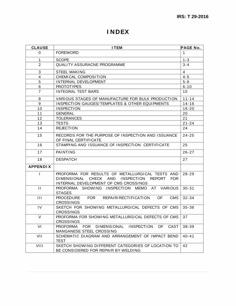
INDEX
CLAUSE ITEM PAGE No. 0 FOREWORD 1
1 SCOPE 1-3 2 QUALITY ASSURACNE PROGRAMME 3-4
3 STEEL MAKING 4 4 CHEMICAL COMPOSITION 4-5 5 INTERNAL DEVELOPMENT 5-6 6 PROTOTYPES 6-10 7 INTEGRAL TEST BARS 10
8 VARIOUS STAGES OF MANUFACTURE FOR BULK PRODUCTION 11-14 9 INSPECTION GAUGES/TEMPLATES & OTHER EQUIPMENTS 14-16 10 INSPECTION 16-20 11 GENERAL 20 12 TOLERANCES 21 13 TESTS 21-24 14 REJECTION 24
15 RECORDS FOR THE PURPOSE OF INSPECTION AND ISSUANCE OF FINAL CERTIFICATE
24-25
16 STAMPING AND ISSUANCE OF INSPECTION CERTIFICATE 25
17 PAINTING 26-27
18 DESPATCH 27
APPENDIX
I PROFORMA FOR RESULTS OF METALLURGICAL TESTS AND DIMENSIONAL CHECK AND INSPECTION REPORT FOR INTERNAL DEVELOPMENT OF CMS CROSSINGS
28-29
II PROFORMA SHOWING INSPECTION MEMO AT VARIOUS STAGES
30-31
III PROCEDURE FOR REPAIR/RECTIFICATION OF CMS CROSSINGS
32-34
IV SKETCH FOR SHOWING METALLURGICAL DEFECTS OF CMS CROSSINGS
35-36
V PROFORMA FOR SHOWING METALLURGICAL DEFECTS OF CMS CROSSINGS
37
VI PROFORMA FOR DIMENSIONAL INSPECTION OF CAST MANGANESE STEEL CROSSING
38-39
VII SCHEMATIC DIAGRAM AND ARRANGEMENT OF IMPACT BEND TEST
40-41
VIII SKETCH SHOWING DIFFERENT CATEGORIES OF LOCATION TO BE CONSIDERED FOR REPAIR BY WELDING
42

IRS: T 29-2016
1 | P a g e
0. FOREWORD
0.1 This specification is issued under the fixed serial number T29-2016, the final
number indicates the year of original adoption as standard or in case of revision,
the year of last revision.
ADOPTED 1974
REVISED 1997
REREVISED 2000
REREVISED 2016
0.2 This specification is revised to incorporate the requirements of corrigenda issued so
far, to include the latest practices & software adopted in testing, rationalization of
inspection procedure by M&C and Engineering officials, to include the casting of
integral test bars, for better traceability and to include latest version of IS codes
relevant to manufacturing of CMS crossings.
1. SCOPE
1.1 This specification covers the requirement of Cast Manganese Steel (CMS) Crossings
for use in Railway Track.
1.2 Reference specifications
A) IS Specifications
1 IS: 2 – 2011 Rules for round off numerical values.
2 IS: 210-2010 Specification for grey iron castings.
3 IS: 228-1987 Methods of chemical analysis of steels (plain
carbon and low alloy steel)
4 IS:12308-1991 Methods of chemical analysis of Cast Iron and Pig
Iron
5 IS: 102-2005 Ready mix paint, brushing, red lead, non-setting,
priming.
IRS: T 29-2016
2 | P a g e
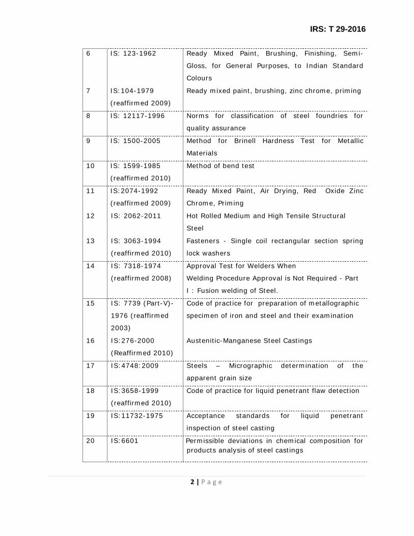
6 IS: 123-1962 Ready Mixed Paint, Brushing, Finishing, Semi-
Gloss, for General Purposes, to Indian Standard
Colours
7 IS:104-1979
(reaffirmed 2009)
Ready mixed paint, brushing, zinc chrome, priming
8 IS: 12117-1996 Norms for classification of steel foundries for
quality assurance
9 IS: 1500-2005 Method for Brinell Hardness Test for Metallic
Materials
10 IS: 1599-1985
(reaffirmed 2010)
Method of bend test
11 IS:2074-1992
(reaffirmed 2009)
Ready Mixed Paint, Air Drying, Red Oxide Zinc
Chrome, Priming
12 IS: 2062-2011 Hot Rolled Medium and High Tensile Structural
Steel
13 IS: 3063-1994
(reaffirmed 2010)
Fasteners - Single coil rectangular section spring
lock washers
14 IS: 7318-1974
(reaffirmed 2008)
Approval Test for Welders When
Welding Procedure Approval is Not Required - Part
I : Fusion welding of Steel.
15 IS: 7739 (Part-V)-
1976 (reaffirmed
2003)
Code of practice for preparation of metallographic
specimen of iron and steel and their examination
16 IS:276-2000
(Reaffirmed 2010)
Austenitic-Manganese Steel Castings
17 IS:4748:2009 Steels – Micrographic determination of the
apparent grain size
18 IS:3658-1999
(reaffirmed 2010)
Code of practice for liquid penetrant flaw detection
19 IS:11732-1975 Acceptance standards for liquid penetrant
inspection of steel casting
20 IS:6601 Permissible deviations in chemical composition for products analysis of steel castings

IRS: T 29-2016
3 | P a g e
B) IRS Specifications
1 IRS: T-12-2009 Flat bottom railway rails
2 IRS: T-23-1967 Track bolts and nuts
3 IRS: M-28-2012 Classification, testing and acceptance criteria of
manual metal arc welding electrode and gas welding
rods.
1.3 All foundries manufacturing CMS Crossing shall be ‘A’ class foundries only and they
shall submit self-assessment report against every clause of IS:12117 to enable
RDSO team to verify the correctness of self-assessment report at the time of
inspection for assessment/periodical reassessment undertaken by RDSO.
1.4 Inspecting authority shall mean RDSO/RITES or any other agency decided by
Railway Board.
1.5 Inspecting official shall mean authorized representative of inspecting authority.
2 QUALITY ASSURACNE PROGRAMME
2.1
The manufacturer shall prepare quality assurance programme (QAP) and submit it
for approval to the inspecting authority and shall obtain his approval before
commencing the manufacture of CMS Crossing. Besides other aspects, the
following salient points shall be taken into consideration for preparation of QAP to
be submitted to Inspecting Authority.
a) Type of scrap to be used.
b) Internal specification of scraps to be used and charge-mix.
c) Moulding Practice
d) Selection of sands to be used
e) Sand binder additives
f) Preparation of sand and its testing
g) Design of mould box and core boxes
h) Pattern and core making
i) Preparation of moulds
j) Melting process

IRS: T 29-2016
4 | P a g e
k) Gas purging technique if any
l) Grain refining technique
m) Stages of testing of molten metal before tapping and at the end of
pouring
n) Shot blasting
o) Fettling i.e. knock out and removal of risers, ingate, fins, etc.
p) Heat treatment process
q) Straightening after heat treatment and after rectification of defects by
welding
r) Removal of protruded metal if any, with the help of air arc
s) Repair by welding
t) Marking for finishing
u) Machine finishing of bottom, fishing planes, top gauge face radius, end
section etc. including drilling holes.
v) Bend test, hardness test, radiographic test, solidity test, non-magnetic
test, D.P. test etc. at the various stages of manufacture in reference to
relevant specification.
w) Maintenance of records of tests at various stages
x) Intensity of internal inspection at different stages by Works
Inspector/Manager (QA)
y) Painting
z) Packing and dispatch
3. STEEL MAKING
3.1 The steel shall be made by electric arc process or such other process as approved
by the Purchaser or his representative. Keeping the limitation of operational
aspects in view, use of induction furnace for melting is not permitted.
4. CHEMICAL COMPOSITION
4.1 The steel used for crossings, when analysed as per relevant parts of IS:12308 or
any other established instrumental method, shall have the following composition:
IRS: T 29-2016
5 | P a g e
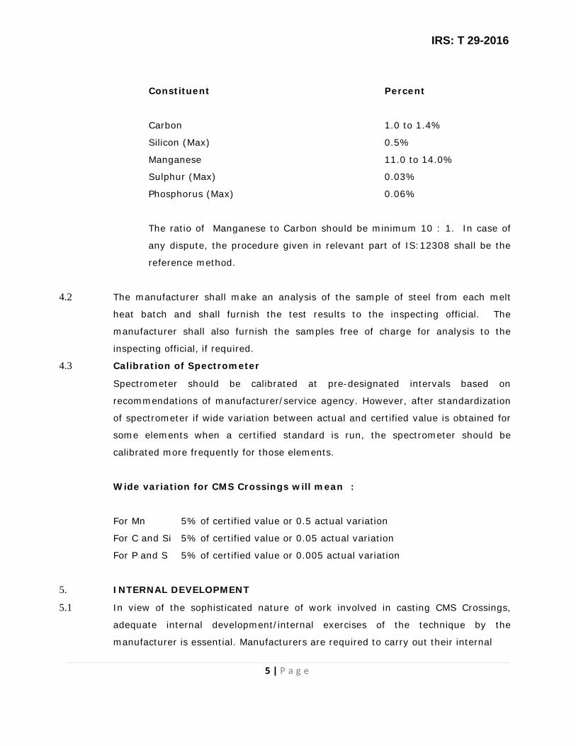
Constituent Percent
Carbon 1.0 to 1.4%
Silicon (Max) 0.5%
Manganese 11.0 to 14.0%
Sulphur (Max) 0.03%
Phosphorus (Max) 0.06%
The ratio of Manganese to Carbon should be minimum 10 : 1. In case of
any dispute, the procedure given in relevant part of IS:12308 shall be the
reference method.
4.2 The manufacturer shall make an analysis of the sample of steel from each melt
heat batch and shall furnish the test results to the inspecting official. The
manufacturer shall also furnish the samples free of charge for analysis to the
inspecting official, if required.
4.3 Calibration of Spectrometer
Spectrometer should be calibrated at pre-designated intervals based on
recommendations of manufacturer/service agency. However, after standardization
of spectrometer if wide variation between actual and certified value is obtained for
some elements when a certified standard is run, the spectrometer should be
calibrated more frequently for those elements.
Wide variation for CMS Crossings will mean :
For Mn 5% of certified value or 0.5 actual variation
For C and Si 5% of certified value or 0.05 actual variation
For P and S 5% of certified value or 0.005 actual variation
5. INTERNAL DEVELOPMENT
5.1 In view of the sophisticated nature of work involved in casting CMS Crossings,
adequate internal development/internal exercises of the technique by the
manufacturer is essential. Manufacturers are required to carry out their internal

IRS: T 29-2016
6 | P a g e
development with the aim of achieving soundness of casting and dimensional
accuracy.
5.2 As a part of internal development, the manufacturers should cast a few crossings
and ensure internal soundness of such castings. Sections shall be cut by abrasive
cutter at the critical locations i.e. 7 sections at a distance of 100mm apart starting
from the nose of the crossing and covering 300 mm on either side as mentioned in
Appendix-I. Non-destructive testing of areas such as flanges, which can be
subjected to radiographic tests, should also be carried out and the manufacturer
should satisfy himself that the standards of acceptance laid down for prototypes in
Clause 6 below are generally achieved during internal development. The
manufacturers shall thereafter approach RDSO. Inspecting official will verify the
report and satisfy himself on the basis of soundness of the cut sections,
dimensional accuracy, records of non-destructive testing and other tests like
chemical composition, bend test etc. that adequate internal development has been
carried out by the manufacturer. Results of detailed dimensional check shall be
recorded in the format prescribed by the inspecting official. The report of internal
development shall be recorded as per proforma at Appendix-I.
5.3 During internal development, inspection procedure detailed at Clause 6 and 10
shall be followed by internal department of the manufacturer and relevant records
shall be maintained for cross checks by the inspecting official.
5.4 After RDSO is satisfied with the internal development on scrutiny of the internal
exercises made by the manufacturer, permission shall be given for casting
prototype crossings. All the relevant papers/documents shall be retained in the
office of the inspecting authority for future reference.
6 PROTOTYPES
6.1 Manufacturing of Prototype
6.1.1 On receipt of permission for casting of prototypes, the manufacturer shall then give
15 days’ notice to RDSO for witnessing of melting and pouring for casting of
prototypes.

IRS: T 29-2016
7 | P a g e
6.1.2 Various stages of manufacture for bulk production as detailed in Clause 8 shall be
followed for manufacture of prototype crossings also.
6.2 Inspection
6.2.1 Surface inspection
All crossings shall be visually inspected for gross surface defects at various stages
of inspection. Dye penetrant methods shall be employed for detection of finer
surface defects. Castings thus inspected shall be free from cracks, shrinkage
cavities, scabs, flakes, blisters, lack of metal, inclusion, porosities, hot tears, cold
shuts and other harmful defects. Minor scattered porosities of less than 4 mm dia
and 1.5 mm depth (provided they are not closer than 15mm from each other and
not more than three nos. at a particular location) shall be considered acceptable.
However, all such defects have to be in a location which is at least 300 mm away
from tip of the nose on its either side. Surface of the casting shall be reasonably
smooth and free from extraneous matters.
6.2.2 Solidity Tests
10% of the prototype castings subject to a minimum of one casting of each type
shall be selected for sectioning at seven locations by abrasive cutter as mentioned
in Clause 5.2 above. Each sectioned face on examination, shall not show a total
defective area of more than 2% of the cross sectional area. The defect shall not
be clustered at any particular location and shall be uniformly distributed
throughout. Defects within 10mm from the surface and defects connected with the
outside and presence of cracks/hot tears shall be cause for rejection. Hardness
of the sectioned faces shall be taken at the center of the thick section. Dye-
penetrant test shall be carried out on sectioned faces for detection of shrinkage
and chequered cracks. These tests shall be carried out physically in the presence
of RDSO representative.
In solidity test, the cross sections shall be plotted on graph sheet in 1:1 scale and
location of defects, if any, shown. The dimensions of flange thickness, wall/web
thickness, roof thickness, head thickness etc shall also be mentioned to give
guidance regarding major defects such as mould disturbance etc.
Subsequent to the clearance of prototype, this test shall be carried out once in the

IRS: T 29-2016
8 | P a g e
three years or completion of manufacturing of 1000 CMS Crossings satisfactorily
whichever is earlier.
6.2.3 Radiographic Examination
Flange portion of the crossing shall be radiographically examined. Radiographs
shall have sensitivity of minimum 2% and satisfy the requirement of ASTM
designation E-446 – Reference Radiographs for Steel Casting – Level II in respect
of blow holes, slag and sand inclusion and shrinkage. No cracks/hot tears shall be
permitted. Radiographic examination shall be done at the rate of 1 in 10 for
regular manufacture and 1 in 5 for prototype castings subject to a minimum of one
casting of each type.
6.2.4 After solidity test and radiographic examination have been certified as satisfactory,
the firm will prepare a document mentioning parameters (methoding size, shape
and location of runners, risers and ingates, moulding practice, source and
properties of prepared sand and metal tapping and pouring parameters) which
gave satisfactory results. This document will be countersigned by inspecting
official. Inspecting officials will be free to verify the parameters which were used
during solidity test and which had been countersigned by inspecting official, so as
to ensure the consistency of foundry practice. These parameters shall then be
incorporated in the QAP.
6.2.5 The manufacturer will inform RDSO about any change in foundry inputs or practice.
RDSO will then decide whether fresh solidity test and higher frequency of
radiography test need to be carried out all over again after judging the impact of
change in input/practice.
6.3 Approval of Prototypes
6.3.1 After RDSO is satisfied with the production of prototypes, approval shall be given
to the firm for undertaking bulk production. All the relevant papers/documents
shall be preserved in the office of the RDSO for future reference. Manufacturer is
to get 10 prototype approved by the RDSO for each design/type of crossing. No
prototype need be produced for repeat order, unless the existing design is modified
considerably.
6.4 Before approaching RDSO for permission for bulk production, the manufacturer
should make good the deficiencies of the plant and machinery, if any, as pointed

IRS: T 29-2016
9 | P a g e
out by the inspecting authority.
6.5 At the time of applying for approval of prototypes by new foundries, the firm shall
submit QAP incorporating records of following aspects of methoding in duplicate
after these parameters have given satisfactory results on solidity and radiographic
tests:
1. Source of
a) Moulding sand
b) Core sand
c) Facing sand
2. Properties of above sand
a) Clay content
b) Purity (major constituents %)
c) AFS and grain fineness number
d) Shape of grains (round, semi-angular, angular)
3. Mould wash
a) Name
b) Base
c) Consistency
d) Size of particles
4. Properties of prepared sands (mould, core and facing )
a) System of sand (CO2, resin bond etc.)
b) Compression strength
c) Shear Strength
d) Collapsibility
5. Feeding system (to be shown on sketch/drawing)
a) Size and position of ingate
b) Size and position of runners
c) Size and position of risers
d) Yield percentage of good castings
6. Pouring start temperature/method of measurement
7. Pouring end temperature/method of measurement.
8. Knock out time after pouring
9. Weight of casting

IRS: T 29-2016
10 | P a g e
These parameters shall be scrutinized by RDSO. These parameters shall then be
incorporated in the QAP. One copy shall be retained by RDSO and the other shall be
returned to the firm after duly signed by the representative of RDSO so as to
enable verification from time to time. In case of any change in the methoding
parameters mentioned above. RDSO shall be informed by the firm to decide
whether the change is minor or major. If the change is expected to affect the
quality of the casting, then it may require revalidation of solidity test.
7. INTEGRAL TEST BARS
7.1 Four number of test bars of size 200 mm X 30 mm X 30 mm (with tolerance of ± 1
mm in each dimension) shall be cast integral to crossing. These shall be located at
toe end and heel end respectively (2 number each).
7.2 Pattern and mould shall be developed by manufacturer to accommodate the
integral test bars.
7.3 Integral test bar shall be so cast that it should not get detached during knock out,
fettling, shot blasting or heat treatment.
7.4 These integral bars shall be used for chemical composition, microstructure/grain
size determination, hardness and for impact bend test.
7.5 Integral test bar shall be detached from crossing by suitable method to avoid any
damage to crossing. The detachment shall only be done in the presence of
inspecting official.
7.6 While detaching the integral test bar at various stages, inspecting official shall
transfer suitable marking on particular test bar so that the same may be identified
in terms of crossing number and location. A record must be maintained for integral
test bars indicating crossing number, location & date of detachment.
7.7 The manufacturer shall preserve at least one integral test bar of each crossing for
minimum 6 months from the date of issue of inspection certificate of particular
crossing and shall present to inspecting official on demand. In case all integral test
bars are used during test/retest, one integral test bar used in Impact Bend Test
may be preserved.

IRS: T 29-2016
11 | P a g e
8. VARIOUS STAGES OF MANUFACTURE FOR BULK PRODUCTION
8.1 Moulding
8.1.1 The crossing shall be accurately moulded and finished to the form and dimensions
shown on the drawings to be supplied by the purchaser or RDSO/Lucknow.
8.1.2 Unless otherwise permitted by the purchaser or the inspecting official in writing the
dimensions/tolerances shown on the drawing (s) shall be adhered to.
8.1.3 Manufacturer should have adequate in-house facility for sand preparation, testing
and recycling as per moulding practice specified in QAP.
8.1.4 Sand selection, moulding and core practice, mould and core paint selection shall be
such that there is no metal mould reaction, which shall cause defects with
bad/rough surface finish.
8.1.5 Internal/external metallic chills or chaplets shall be avoided to ensure the
consistent internal quality requirement.
8.2 Marking
8.2.1 All crossings shall have the markings of drawing number of crossing, rail section,
maker’s name or initials, month and year of manufacture and such other markings
as may be specified by the purchaser or the inspecting official cast in an approved
manner. These markings shall be cast in raised letters 40mm high and 3mm deep
on outer faces of webs of the crossing unit. All these markings shall be sharp,
clear and distinct.
8.3 Melting
8.3.1 Suitable efforts shall be made for selection of proper scrap and use of correct
melting process with proper refining operation shall be ensured so as to control the
detrimental tramp elements in steel. Moreover, the sulphur and phosphorus
contents in the steel shall be achieved as mentioned in Clause 4.1.
8.4 Pouring
8.4.1 Metal should be poured by bottom pouring ladle and mould filling time shall be
recorded. Further, each manufacturer will indicate pouring start and pouring end
temperatures in his QAP after ensuring that all castings from first to last are sound
and no adverse effect are noticed due to high or low temperature of pouring.
Pouring start and pouring end temperatures will be measured and records kept.

IRS: T 29-2016
12 | P a g e
8.4.2 Any casting for which witnessing of melting & pouring is mandatory, the
manufacturer shall give prior notice to the inspecting authority. Inspecting official
shall witness melting & pouring as per clause 10.2.1. Casting for which witnessing
of melting & pouring is not mandatory, the manufacturer may cast the same
keeping records as indicated in clause 10.2.2.
8.5 Knock Out
8.5.1 During knock out, casting should be handled very carefully to avoid development
of cracks in the castings. Any impact shall be avoided.
8.6 Fettling and shot blasting
8.6.1 The crossing shall be free from embedded sand particles and risers, flow off shall
be knocked off, ingate at ends and other thick fins, if any, shall be removed by Arc
Air or oxy-cut. If oxy-cut, then the cut should be at least 25mm away from the
crossing body. The casting shall be suitably shot blasted thereafter, so that they
are free from sand etc. and surface inspection can be done visually by the
inspecting official without any difficulty. In no case, crossing shall be placed on
shaker for removal of sands. Fettling & shot blasting shall be done in such a way
so as to avoid any impact to the crossing.
8.6.2 When ingate riser etc. are removed by thermal operation, care shall be taken to
make the cut with sufficient allowance ( at least 25mm away from the crossing
body) to prevent any defect being introduced into the main body of the crossing
due to local heating.
8.6.3 Enlargement of bolt-holes and making of any new holes by thermal operation shall
not be permitted.
8.6.4 All crossings shall be free from gas pockets, sand holes, cracks, cold shuts and
other injurious defects. Lumps and sharp fins, if any, on the edges of the casting
shall be suitably removed.
8.6.5
8.6.6
Repair of defects by welding that will not ultimately impair the strength or utility of
the crossing, may be carried out with the consent of the inspecting officer, as per
approved process as mentioned in Appendix-III.
During fettling for removing risers, runners and ingates from castings, no
excessive heat should be generated to avoid any thermal shock to the casting.

IRS: T 29-2016
13 | P a g e
8.7
8.7.1
Heat treatment of crossings
All crossings along with integral test bars shall suitably be heat treated to render
them tough. It shall be ensured that integral test bars meant for further testing is
not detached from the crossing even after heat treatment and shot blasting to
facilitate inspecting officials in carrying out the test related to particular crossing.
This treatment shall consist of uniform heating of the crossing to a suitable
temperature holding it at that temperature till uniformly heated throughout and
quenching in water within 60 seconds from a minimum temperature of 1050oC. The
crossing should be kept in the quenching tank in head down manner. The initial
temperature of water in the quenching tank shall be less than or equal to 300C and
should not rise by more than 100C during and immediately after quenching of
crossings. Water in quenching tank shall be agitated and circulated properly and a
continuous temperature measuring system should be installed to record before and
after quenching temperature of tank for each heat treated batches of crossings.
The recording of temperature should be kept preserved for checking of inspecting
officials.
8.7.2 The heat treatment shall be done in a furnace fitted with recorder type pyrometer.
The number of castings for each heat treatment batch indicating melt heat number
shall be recorded on the heat treatment chart and it shall be signed by the
manufacturer’s representative and produced to the inspecting official on demand.
8.7.3 On completion of heat treatment, the crossing again shall be shot blasted.
8.7.4 A record of the heat treatment of the crossing shall be maintained by the
manufacturer, details of which shall be supplied to the inspecting official.
8.8 Surface Preparation and defects removal
8.8.1 The castings shall be suitably prepared for the removal/rectification of castings
defects as permitted by the inspecting official without resorting to any thermal
operation.
8.8.2 Continuous grinding at one location shall not be done to avoid raising of
temperature of the surface during grinding beyond 2500C.
8.9 Straightening
8.9.1 The casting after complete repair work and certification to that effect by the
manufacturer shall only be straightened by application of gradual load under a
suitable heavy duty hydraulic press. Casting shall be summarily rejected, if end-
to-end straightening is beyond 40mm.

IRS: T 29-2016
14 | P a g e
8.9.2 After the pressing operation is done, the casting shall be offered to the Inspecting
official for inspection by dye-penetration test and records shall be maintained. In
no case, straightening operation will be allowed before undertaking repair welding.
8.10 Finishing
8.10.1 Surface finish shall be ensured to minimize machining on any part of crossing.
Ideal finish shall be taken as glass finish.
8.10.2 The bottom of crossing shall be machined by milling machine so that the bottom
surface of crossing which rests on PSC sleepers shall be straight without twists and
shall be free from such imperfections which may prevent a good and even bearing
of the crossing on PSC sleepers.
8.10.3 End section faces (both toe and heel end) shall be machine-finished by milling
machine to provide machined joints in turnout as mentioned in the drawing.
8.10.4 Fishing plane shall be finished by milling for achieving required surface contact
between fish plate and casting to have sturdy joint for proper transfer of dynamic
load.
8.10.5 Fish bolt holes shall be drilled and have a 1mm chamfer at each end to achieve
tolerances mentioned in the drawing. Bond holes in fish plate area for DC traction
shall also be drilled for getting bond wires force fitted.
8.10.6 The top edge contour (gauge face) upto tangent points shall be machine-finished
by planer/miller in order to achieve uniform radius all through running faces and to
eliminate local misalignment.
8.10.7 Other locations shall be finished either by machining or by hand grinding operation
depending upon the facilities available. While grinding, clause 8.8.2 shall be
adhered to.
8.10.8 Machining facility shall be generally available in the same premises to have
dedicated flow line for manufacture of this sophisticated safety related item.
9 INSPECTION GAUGES/TEMPLATES & OTHER EQUIPMENTS
9.1 Manufacture of inspection gauges
The manufacturer shall prepare two sets of inspection gauges/templates as per
drawings to be supplied/approved by the purchaser/Inspecting authority for each
type of CMS crossings ordered and shall submit them for approval to the purchaser
or the inspecting official and shall obtain his approval before commencing

IRS: T 29-2016
15 | P a g e
manufacture of prototype CMS Crossing. The crossings shall be checked with the
help of approved inspection gauges/templates at different locations as mentioned
in the gauge drawing. Out of the two sets of gauges/templates approved, one set
is to be kept as MASTER GAUGE for use in case of any discrepancy and the other
set is to be used for finishing of crossings in shop floor and by Inspecting Officials
during inspection. Extra sets of gauges shall also be made depending upon the
rate of production and got approved by the Inspecting Authority. The inspection
gauges shall be verified during Quality Audit. These gauges may also be checked
as and when considered necessary during inspection.
9.2 Other inspection equipment/accessories
The following materials shall be made available before approval of internal
development for checking end fitments of each CMS Crossing.
9.2.1 Rail pieces of standard section 750 mm long (approx.) having standard fish bolt
holes at one end matching with the section of CMS Crossing to be inspected. Four
such rail pieces shall be made available for checking one crossing. Number of rail
pieces required shall depend upon the number of crossings to be put up at a time
for inspection. End face of rail pieces shall be machined to have frozen/machined
joint as mentioned in the respective assembly drawing of CMS Crossing. Bolt
holes in the back of rails shall register with reference to the base of the rail within
± 0.8 mm provided that fish bolt holes shall register within ± 0.6 mm in location
and in diameter for the purpose of machined joint.
9.2.2 Bolts of sizes as per drawing.
9.2.3 Fish plates of standard section with six bolt holes matching with the CMS crossings.
Four fish plates will be required per crossing. Second quality/second hand fish
plate shall not be used.
9.2.4 Distance blocks for ends as mentioned in drawings. These web and fishing fit
blocks shall be finished by machining before use.
9.2.5 Adequate number of spherical washers, packing pieces and tapered washers as
mentioned in the relevant drawings.
9.2.6 Other standard equipment such as tape (steel 10 m), straight edge (steel 1 m
long), scale steel (305 mm-610 mm), Nylon cord (10 m), filler gauge having strips
of 0.5mm to 1.0mm and scale vernier of 600 mm long.

IRS: T 29-2016
16 | P a g e
9.2.7 Any other equipment specified by purchaser/inspecting authority
9.2.8 These accessories/other equipment shall be maintained for regular inspection also.
10. INSPECTION
10.1 The CMS crossing is related to the public safety in the railway transit. The process
of manufacture is most intricate both from the foundry and metallurgical point of
view. Considering the basic characteristic of the steel i.e. the thermal sensitivity,
low diathermic character, mould metal reactivity of the steel, and the work
hardening and high shrinkage characteristics of the steel, rigorous inspection (both
metallurgical and dimensional) at different stages of manufacture shall be carried
out as detailed herein.
10.2 Chemical composition
10.2.1 For casting of prototypes , the manufacturers shall intimate the inspecting
authority well in advance (at least 15 days) so as to enable him to witness
sampling of molten steel at different stages for chemical analysis and shall furnish
details of charge, pouring temperature etc. Inspecting official shall witness such
pouring and ensure that temperature and chemical composition as mentioned in
QAP has been met with. The bath samples shall be taken at different stages and
chemical composition shall be carried out. The same shall be recorded with other
parameters in inspection memo-I as given in Appendix-II.
10.2.2 For casting that does not require pouring witness, the manufacturer may go ahead
with the casting and record the parameters in inspection memo-I as given in
Appendix-II The records shall be presented to the inspecting officials for cross
check during subsequent stages of inspection. Chemical composition of such
crossings at any stage shall be determined as per clause 10.4.2.2.
10.3 Identification of cast and correlation of heat numbers
10.3.1 The castings shall bear manufacturer’s identification marks, drawing number, serial
number and date of cast. A register shall be maintained by the manufacturer
correlating the casting serial number and heat number and register shall be
produced to the Inspecting Authority for their verification on demand.
10.4 STAGES OF INSPECTION
10.4.1 Inspection shall be carried out in four stages i.e. Stage-I, Stage-II and Stage-III
and Stage IV (final stage). Sampling of molten metal may also be witnessed by

IRS: T 29-2016
17 | P a g e
Inspecting Official, if available in shop-floor during pouring. However it shall be
ensured that pouring must be witnessed at-least once in every 6 months. Prior to
Stage-I inspection, wherever applicable, chemical composition shall be checked as
per Clause 10.2.1.
For the designs of CMS Crossing manufactured by any firm, consistency of quality
of which has been established as per norms prescribed by inspecting authority,
inspecting official(s) shall begin inspection at Stage-II. The internal inspection
shall, however, be carried out by the manufacturer at Stage-I which shall be
verified by the inspecting official(s) at Stage-II.
10.4.1.1 Stage-I: Inspection shall be carried out after knockout/oxy-cutting/shot blasting
etc. as per Clause 10.4.2.
10.4.1.2 Stage-II: Inspection shall be carried out after heat treatment and shot blasting
etc. as per clause 10.4.3.
10.4.1.3 Stage-III: Inspection shall be carried out after removal/rectification of defects
and straightening as per clause 10.4.4.
10.4.1.4 Stage-IV (Final stage): Inspection shall be carried out after final finishing for
final acceptance as per clause 10.4.5.
10.4.2 Metallurgical & Chemical inspection (Stage-I)
10.4.2.1 After fettling and shot blasting as per clause 8.6, the defective areas of the surface
of crossing, if any, shall be marked with the dimension of defects (i.e., length,
width and depth) and shown in isometric view as shown in Appendix-IV and their
locations indicated from a datum line. These details are to be tabulated by the
manufacturer in a proforma as per Appendix-V and shall be submitted to the
inspecting official for the verification and inspection. The inspecting official shall
be vigilant about foundry defects like cracks, sand holes, cold shuts, pin holes
porosity, extra metal, sand fusion etc. Crossing having cracks shall be straight way
rejected.
10.4.2.2 One integral test bar shall be detached randomly from any crossing in a melt heat
batch in a manner prescribed in clause 7.5 & 7.6. The chemical composition shall
be determined by taking sample from the integral test bar so detached which shall
represent the entire melt heat batch. In cases where inspection is started by
inspecting official at Stage-II as mentioned in clause 10.4.1, integral test bar shall

IRS: T 29-2016
18 | P a g e
be detached for determination of chemical composition in presence of inspecting
official at Stage-II only i.e. after heat treatment and shot blasting.
10.4.2.3 The castings which are considered processable both metallurgically and chemically
at this stage by the ‘manufacturer and inspecting official’ or the ‘manufacturer’ as
the case may be , shall be permitted for heat treatment as per clause 8.7 and
inspection memo-II as mentioned in Appendix-II shall be signed.
10.4.3 Metallurgical & Dimensional Inspection (Stage-II)
10.4.3.1 After heat treatment as per Clause 8.7 and shot blasting, the castings shall be
offered to the inspecting official in the similar manner as in Stage-I for
metallurgical and dimensional checkup. Surface inspection shall be carried out as
detailed in clause 6.2.1 and 10.4.2.1 & defects shall be marked on isometric view &
recorded in proforma given in Appendix-IV & V respectively. The chemical
composition of crossing shall be determined by taking sample from the integral
test bar as detailed in 10.4.2.2, if not done earlier.
10.4.3.2 Crossings having crack(s) shall be rejected.
10.4.3.3 Integral test bars shall be detached from crossing in a manner prescribed in clause
7.5 & 7.6. Impact bend test on integral test bar shall be conducted as per para
13.1 in presence of the inspecting official and record of test shall be maintained.
Suitable hardness test shall be conducted at this stage on casting/integral test bar
as per para 13.2 in presence of inspecting official and record shall be maintained.
10.4.3.4 The micro test piece shall be cut from the integral test bar duly heat treated along
with CMS crossing as per para 8.7 for determination of grain size and
microstructure as per para 13.4.
10.4.3.5 At this stage, gross dimensions such as overall length, distance between actual
nose and heel, actual nose and toe end, height at different locations, flange
thickness at different locations, flange way clearance, throat clearance, flange well
depth, wheel tread at toe end, nose thickness, nose depression and off sets
bottom, bottom width, tie thickness, extent of vertical bend etc. shall be checked
and recorded in inspection memo-IV as mentioned in Appendix-II
10.4.3.6 The castings after metallurgical and dimensional inspection, shall be considered for
further processing as per clause 10.4.4 and inspection memo-III & IV as

IRS: T 29-2016
19 | P a g e
mentioned in Appendix-II shall be signed by the inspecting officials along with the
isometric view.
10.4.4 Metallurgical Inspection (Stage-III)
10.4.4.1 Before putting up to the inspecting officials, the castings shall be suitably prepared
for the removal/rectification of defects as identified during stage-I/stage-II as per
Clause 8.8 and straightened as per Clause 8.9. No crack shall develop on locations
repaired by welding, due to straightening operation & the same shall be verified by
conducting dye penetration test.
10.4.4.2 Repair welding shall be done strictly as per the procedure for repair/rectification of
CMS crossing at Appendix-III. The manufacturer will produce a certificate to this
effect.
10.4.4.3 The castings shall be offered to the inspecting official in the manner as in Stage-I
and Stage-II for metallurgical inspection, if necessary. For the designs of CMS
Crossing manufactured by any firm, consistency of quality of which has been
established as per norms prescribed by inspecting authority, casting shall be
offered to inspecting official for inspection during Stage IV/Final Inspection. In such
cases, the internal inspection shall, however, be carried out by the manufacturer at
Stage-III which shall be verified by the inspecting official(s) at Stage-IV/Final
Inspection.
10.4.4.4 The crossings which are considered processable shall be permitted for final
finishing by the ‘manufacturer and inspecting official’ or the ‘manufacturer’ as the
case may be and inspection memo-V as mentioned in the Appendix-II shall be
signed.
10.4.5 Final dimensional checkup and magnetic test (Stage-IV/Final Stage)
10.4.5.1 After final inspection and certification by the Works Inspector of the firm as per
Clause 15, the crossing shall be offered finally for dimensional checkup (as per
sequence shown in Appendix-VI) on the inspection table/marking table with the
approved gauges/templates/equipment as mentioned in Clause 9.2.
10.4.5.2 The castings shall be visually inspected for surface defects employing dye-
penetrant tests as necessary. The casting shall also be tested for its non-magnetic
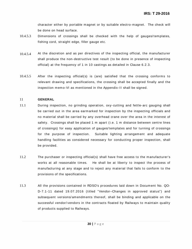
IRS: T 29-2016
20 | P a g e
character either by portable magnet or by suitable electro-magnet. The check will
be done on head surface.
10.4.5.3
10.4.5.4
Dimensions of crossings shall be checked with the help of gauges/templates,
fishing cord, straight edge, filler gauge etc.
At the discretion and as per directives of the inspecting official, the manufacturer
shall produce the non-destructive test result (to be done in presence of inspecting
official) at the frequency of 1 in 10 castings as detailed in Clause 6.2.3.
10.4.5.5 After the inspecting official(s) is (are) satisfied that the crossing conforms to
relevant drawing and specifications, the crossing shall be accepted finally and the
inspection memo-VI as mentioned in the Appendix-II shall be signed.
11 GENERAL
11.1 During inspection, no grinding operation, oxy-cutting and fettle-arc gauging shall
be carried out in the area earmarked for inspection by the inspecting officials and
no material shall be carried by any overhead crane over the area in the interest of
safety. Crossings shall be placed 1 m apart (i.e. 1 m distance between centre lines
of crossings) for easy application of gauges/templates and for turning of crossings
for the purpose of inspection. Suitable lighting arrangement and adequate
handling facilities as considered necessary for conducting proper inspection, shall
be provided.
11.2 The purchaser or inspecting official(s) shall have free access to the manufacturer’s
works at all reasonable times. He shall be at liberty to inspect the process of
manufacturing at any stage and to reject any material that fails to conform to the
provisions of the specifications.
11.3 All the provisions contained in RDSO’s procedures laid down in Document No. QO-
D-7.1-11 dated 19.07.2016 (titled ”Vendor–Changes in approved status”) and
subsequent versions/amendments thereof, shall be binding and applicable on the
successful vendor/vendors in the contracts floated by Railways to maintain quality
of products supplied to Railways.
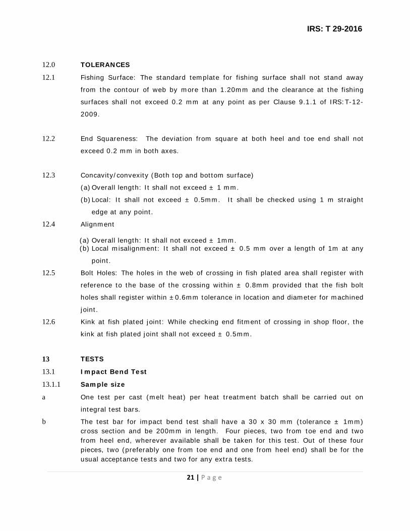
IRS: T 29-2016
21 | P a g e
12.0 TOLERANCES
12.1 Fishing Surface: The standard template for fishing surface shall not stand away
from the contour of web by more than 1.20mm and the clearance at the fishing
surfaces shall not exceed 0.2 mm at any point as per Clause 9.1.1 of IRS:T-12-
2009.
12.2 End Squareness: The deviation from square at both heel and toe end shall not
exceed 0.2 mm in both axes.
12.3 Concavity/convexity (Both top and bottom surface)
(a) Overall length: It shall not exceed ± 1 mm.
(b) Local: It shall not exceed ± 0.5mm. It shall be checked using 1 m straight
edge at any point.
12.4 Alignment
(a) Overall length: It shall not exceed ± 1mm. (b) Local misalignment: It shall not exceed ± 0.5 mm over a length of 1m at any
point.
12.5 Bolt Holes: The holes in the web of crossing in fish plated area shall register with
reference to the base of the crossing within ± 0.8mm provided that the fish bolt
holes shall register within ±0.6mm tolerance in location and diameter for machined
joint.
12.6 Kink at fish plated joint: While checking end fitment of crossing in shop floor, the
kink at fish plated joint shall not exceed ± 0.5mm.
13 TESTS
13.1 Impact Bend Test
13.1.1 Sample size
a One test per cast (melt heat) per heat treatment batch shall be carried out on
integral test bars.
b The test bar for impact bend test shall have a 30 x 30 mm (tolerance ± 1mm) cross section and be 200mm in length. Four pieces, two from toe end and two from heel end, wherever available shall be taken for this test. Out of these four pieces, two (preferably one from toe end and one from heel end) shall be for the usual acceptance tests and two for any extra tests.

IRS: T 29-2016
22 | P a g e
There may be cases where only three test bars are available (e.g. single crossing
of particular melt heat and heat treatment batch, one test bar of which has been
detached for chemical composition determination earlier). In such case, three
pieces shall be taken, out of which two shall be used for usual acceptance test and
balance one piece for retest.
c Casting and detachment of integral test bar shall be done in a manner prescribed
in clause 7.0
13.1.2 Execution of Tests:
a The impact bend test pieces shall be of un-machined bar, the edges of which may
have a chamfer not exceeding 1 mm. Prior to the test, bars shall be notched in a
press to a semi-circle (r=1.5mm, depth=1.5mm) on one face at the center across
throughout the width in the presence of inspecting official.
b The test pieces shall then be placed horizontally on two knife-edge supports spaced
160mm apart, notch downwards and midway between the two supports. The knife
edge supports shall have a radius of 2mm. The test pieces must withstand 3
successive blows of a 50 kg weight falling freely from a height of 3m onto the
surface opposite the notch. The part of the falling weight coming into contact with
the test piece shall be rounded to a radius of 50 mm. The test arrangement shall
be as per Appendix-VIII
13.1.3 Acceptance Criteria
(i) The test pieces must withstand three impacts. They may crack but the
crack must not extend more than 7 mm up.
(ii) Both test pieces must comply with the above acceptance conditions for the
castings of particular melt heat & heat treatment batch to be acceptable.
(iii) In case only three test pieces are available for impact bend test as
mentioned at 13.1.1(b), if both test pieces give unsatisfactory results, then
castings of particular melt heat & heat treatment batch shall definitely be
rejected.
13.1.4 Extra Tests– Further Heat Treatment
If one (in case of availability of only three test pieces as mentioned at 13.1.1(b))
or one/both (in other cases) impact bend tests give unsatisfactory results, the
supplier may opt to request an extra test to be performed.
(i) On the casting as it is.

IRS: T 29-2016
23 | P a g e
(ii) On the casting after further heat treatment. This, however, shall be
possible only on a casting in the unfinished stage.
(iii) The extra test shall be carried out on the remaining two/one test piece subject
to the same conditions as set out above for the first two tests. If one or both
extra tests, gives unsatisfactory results, the castings of particular melt heat & heat
treatment batch shall definitely be rejected.
13.2 Hardness Test
13.2.1 Sample size
On every crossing, two locations shall be selected at thin & thick section
respectively.
13.2.2 Method of execution and acceptance criterion
13.2.2.1 The crossing, when tested for hardness by a portable hardness testing method
approved by inspecting official, shall have a Brinell Hardness number not more
than 229 or equivalent.
13.2.2.2 The integral test bar used for impact bend test shall also be selected for making
sample for hardness test representing particular melt heat. The sample
representing the particular melt heat shall be tested for hardness, in accordance
with IS 1500 or the latest adopted revision in vogue and it shall have a Brinell
Hardness number not more than 229 or equivalent.
13.3 Retest
13.3.1 Should any of the samples tested fail to meet the requirement of Clause 13.1 or
13.2 or both, the manufacturer with the approval of the purchaser or the
inspecting officer may reheat-treat the castings together with the test bars and
resubmit for test.
13.3.2 Re-testing procedure shall be as prescribed in Clauses 13.1 and 13.2.
13.4 Grain size and microstructure
13.4.1 Sample size
Micro test piece shall be prepared from the integral test bar used for making
samples for impact bend test.
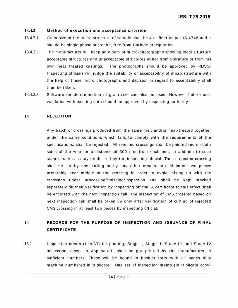
IRS: T 29-2016
24 | P a g e
13.4.2 Method of execution and acceptance criterion
13.4.2.1 Grain size of the micro structure of sample shall be 4 or finer as per IS 4748 and it
should be single phase austenite, free from Carbide precipitation.
13.4.2.2 The manufacturer will keep an album of micro-photographs showing ideal structure
acceptable structures and unacceptable structures either from literature or from his
own heat treated castings. The photographs should be approved by RDSO.
Inspecting officials will judge the suitability or acceptability of micro structure with
the help of these micro photographs and decision in regard to acceptability shall
then be taken.
13.4.2.3 Software for determination of grain size can also be used. However before use,
validation with existing data should be approved by inspecting authority.
14 REJECTION
Any batch of crossings produced from the same melt and/or heat-treated together
under the same conditions which fails to comply with the requirements of the
specifications, shall be rejected. All rejected crossings shall be painted red on both
sides of the web for a distance of 300 mm from each end, in addition to such
stamp marks as may be desired by the inspecting official. These rejected crossing
shall be cut by gas cutting or by any other means into minimum two pieces
preferably near middle of the crossing in order to avoid mixing up with the
crossings under processing/finishing/inspection and shall be kept stacked
separately till their verification by inspecting official. A certificate to this effect shall
be enclosed with the next inspection call. The inspection of CMS crossing based on
next inspection call shall be taken up only after verification of cutting of rejected
CMS crossing in at least two pieces by inspecting official.
15 RECORDS FOR THE PURPOSE OF INSPECTION AND ISSUANCE OF FINAL
CERTIFICATE
15.1 Inspection memo (I to VI) for pouring, Stage-I, Stage-II, Stage-III and Stage-IV
inspection shown in Appendix-II shall be got printed by the manufacturer in
sufficient numbers. These will be bound in booklet form with all pages duly
machine numbered in triplicate. One set of inspection memo (in triplicate copy)

IRS: T 29-2016
25 | P a g e
shall be used for recording details of only one crossing during its different stages of
m manufacture/inspection.
15.2 A register shall be maintained by the manufacturer giving the details of crossing,
i.e. date of casting, batch number, date of inspection at different stages and date
of issue of inspection certificate.
15.3 Before the crossings are submitted to the inspecting official for inspection, the
manufacturer shall have examined these crossings and all defective crossings shall
be disposed of in a manner specified in Clause 14.
15.4 The manufacturer shall provide to the inspecting official free of charge all tools and
labour and gauges/templates required for inspection and also office
accommodation with sitting arrangements, light, fan etc. for doing necessary paper
work. The manufacturer shall also provide industrial helmet to inspecting official
for use during inspection on shop floor.
15.5 No crossing shall be packed until it has been inspected, approved/accepted,
stamped by the inspecting official. Crossings shall be dispatched only after issue of
Dispatch memo/Inspection Certificate by the authorized inspecting official.
16 STAMPING AND ISSUANCE OF INSPECTION CERTIFICATE
16.1 Crossing thus cleared shall be offered to the inspecting official for necessary
stamping with inspecting official’s steel stamp insignia. Inspection stamp shall be
marked on top surface of the left hand wing 25mm away from heel end.
16.2 After acceptance of crossing as per Clause 10.4.5.5 and stamping as per Clause
16.1 above, inspection certificate shall be issued by the inspecting official
authorized by the competent authority.

IRS: T 29-2016
26 | P a g e
17 PAINTING
17.1 Stamped crossing shall be thoroughly cleaned to remove rust, scale dirt and oil and
received primer coats on each surface to one of the following schedules:
(a) One coat of ready mixed paint brushing red lead non-setting priming to
IS: 102(latest adopted revision in vogue).
or
(b) One coat of ready-mixed paint, brushing zinc chrome priming to
IS:104(latest adopted revision in vogue) followed by one coat of ready mixed
paint and drying red oxide-zinc chrome, priming to IS:2074(latest adopted
revision in vogue) .
or
(c) Two coats of ready-mixed paint, air drying red oxide, zinc chrome
priming to IS: 2074(latest adopted revision in vogue).
or
(d) Two coats of red-oxide, zinc chromate primer to IRS specification no. P-
31(latest adopted revision in vogue).
17.2 The primer coats as indicated in Clause 17.1(b), (c) and (d) shall be protected by
one finishing coat of ready-mixed paint, brushing, finishing, semi-gloss to
IS:123(latest adopted revision in vogue)
17.3 The paint shall be applied by brush. The first priming coat shall be applied within
four hours after cleaning etc. The second priming coat shall be applied when the
first priming coat has dried. The finishing coat shall be applied when the second
priming coat has dried. The dry film thickness of the two coats of primer shall not
be less than 40 microns and the complete system inclusive of finishing coat not
less than 80 microns. Record of painting process shall be maintained.
17.4 The inspecting officials shall check the quality of paints that will be used as per
relevant specifications once in two months or after painting of every lot of 200

IRS: T 29-2016
27 | P a g e
crossings.
17.5 Quality of painting shall be checked at random once in a month as and when
inspecting official is available in shop floor.
18.0 DESPATCH
All crossings, after approval, shall be loaded in a systematic manner to the
satisfaction of inspecting official to avoid any damage in transit.
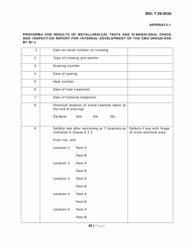
IRS: T 29-2016
28 | P a g e
APPENDIX-I
PROFORMA FOR RESULTS OF METALLURGICAL TESTS AND DIMENSIONAL CHECK AND INSPECTION REPORT FOR INTERNAL DEVELOPMENT OF THE CMS CROSSINGS BY M/s
1 Cast-on-serial number on crossing
2 Type of crossing and section
3 Drawing number
4 Date of casting
5 Heat number
6 Date of heat treatment
7 Date of material inspection
8 Chemical analysis of metal (sample taken at the end of pouring) C% Mn% Si% S% P%
9 Solidity test after sectioning at 7 locations as indicated in Clause 6.2.2. From toe, end Location-1 Face A Face B Location-2 Face A Face B Location-3 Face A Face B Location-4 Face A Face B Location-5 Face A Face B
Defects if any with %age of cross-sectional area

IRS: T 29-2016
29 | P a g e
Location-6 Face A Face B Location-7 Face A Face B
10 Results of bend tests conducted on integral test bar
11 Surface condition (visual) (Defects, if any, shall be shown on a sketch at Appendix-IV).
12 Result of Radiographic test conducted on flanges as indicated in Clause 6.2.3
13 Result of Hardness test (BHN) on top and sectional faces of pieces (7 Nos.) obtained after solidity test.
14 Result of dimensional check recorded in the format prescribed by the inspecting official.
Manager (QC) of the firm

IRS: T 29-2016
30 | P a g e
APPENDIX-II

IRS: T 29-2016
31 | P a g e

IRS: T 29-2016
32 | P a g e
APPENDIX-III
PROCEDURE FOR REPAIR/RECTIFICATION OF CMS CROSSIGNS BY WELDING
1.0 LIMITATIONS
1.1 Crossings which are found metallurgically acceptable by the inspecting official,
shall only be put up for dimensional inspection. The details of dimensional
deviations of the crossings, if any, may be indicated on the sketch as shown in
Appendix-IV and put up to the inspecting official.
1.2 Crossing surfaces/areas/locations i.e. running surfaces, non-running surface,
highly stressed locations, nose, wings on either side of nose shall be broadly
classified in the following categories (as shown in Appendix-VIII) depending
upon their criticality from the service considerations, for the purpose of repair
by welding:
Category-I: 300mm of the top of nose, 300mm of the wings on either side of
actual nose of crossing and edges of both top and bottom flanges (upto 25mm
from edge).
Category-II: Running surface other than the area mentioned in Category-I.
Category-III: Non-running surface other than the area mentioned in
Category-IV and top surface of “Vee” not coming in contact with running
wheels of rolling stock.
Category-IV: Non-vulnerable areas like bearing plates, walls of end sections
(excluding head portion).
1.2.1 At locations covered in category-I, no casting defects shall be permitted.
1.2.2 At locations covered in Category-II, no rectification shall be allowed on the
running surface. Scattered minor defects (excluding cracks) of size less than
4mm dia and upto 1.5mm depth anywhere on this area of the casting shall be
left as such, provided these defects are at a minimum distance of 15mm from
each other and not more than 3 numbers in a particular location.

IRS: T 29-2016
33 | P a g e
1.2.3 At locations covered in Category-III, defects appearing in the crossing surface
shall be permitted to be rectified by welding adopting the usual procedure and
precautions at the discretion of the inspecting official.
1.2.4 At locations covered in Category-IV, surface defects of size<30mm in diameter
and depth <1/3 of thickness may be permitted to be rectified by welding
taking necessary precautions and with the knowledge of the inspecting official
and to be recorded in the final inspection certificate.
2.0 PROCEDURE FOR WELDING
2.1 Before carrying out weld-reclamation, the defective areas shall be removed by
grinding/gauging. The locations shall be tested by dye-penetrant to ensure
complete freedom from the cracks. These operations, grinding/gauging and
testing shall be repeated till the area is free from the defects and cracks.
2.2 Only those crossings which are considered suitable for rectification by welding
shall be rectified by using any of these brands of electrodes approved by RDSO
under Class H3 of IRS:M-28.
These crossings can also be reconditioned/rectified by using H3B and higher
category, hard facing electrodes. Maximum upto 4mm dia electrodes shall
only be used to avoid high heat input.
2.3 The electrodes shall be dried at the specified temperature and time as per the
recommendations of the electrode manufacturer. The electrodes having
cracked and damaged flux covering shall be discarded.
2.4 Welding shall be carried out using DC welding generator with reversed polarity
using the lower limit of the current range or as recommended by the electrode
manufacturer and shortest possible arc length practicable during welding, so
as to reduce the heat input in the base metal, thereby reducing the dilution of
the weld metal which would otherwise cause embrittlement of the weld.
2.5 Welding shall be intermittent so that at no time more than one run is
deposited simultaneously and welding is not done continuously for more than
2 minutes at a stretch.
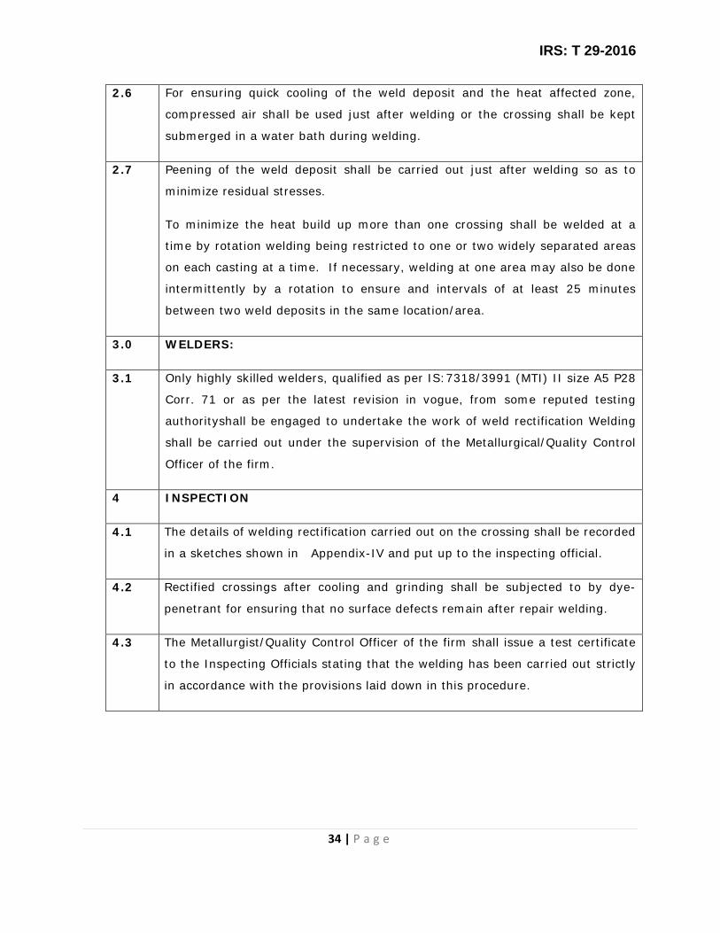
IRS: T 29-2016
34 | P a g e
2.6 For ensuring quick cooling of the weld deposit and the heat affected zone,
compressed air shall be used just after welding or the crossing shall be kept
submerged in a water bath during welding.
2.7 Peening of the weld deposit shall be carried out just after welding so as to
minimize residual stresses.
To minimize the heat build up more than one crossing shall be welded at a
time by rotation welding being restricted to one or two widely separated areas
on each casting at a time. If necessary, welding at one area may also be done
intermittently by a rotation to ensure and intervals of at least 25 minutes
between two weld deposits in the same location/area.
3.0 WELDERS:
3.1 Only highly skilled welders, qualified as per IS:7318/3991 (MTI) II size A5 P28
Corr. 71 or as per the latest revision in vogue, from some reputed testing
authorityshall be engaged to undertake the work of weld rectification Welding
shall be carried out under the supervision of the Metallurgical/Quality Control
Officer of the firm.
4 INSPECTION
4.1 The details of welding rectification carried out on the crossing shall be recorded
in a sketches shown in Appendix-IV and put up to the inspecting official.
4.2 Rectified crossings after cooling and grinding shall be subjected to by dye-
penetrant for ensuring that no surface defects remain after repair welding.
4.3 The Metallurgist/Quality Control Officer of the firm shall issue a test certificate
to the Inspecting Officials stating that the welding has been carried out strictly
in accordance with the provisions laid down in this procedure.
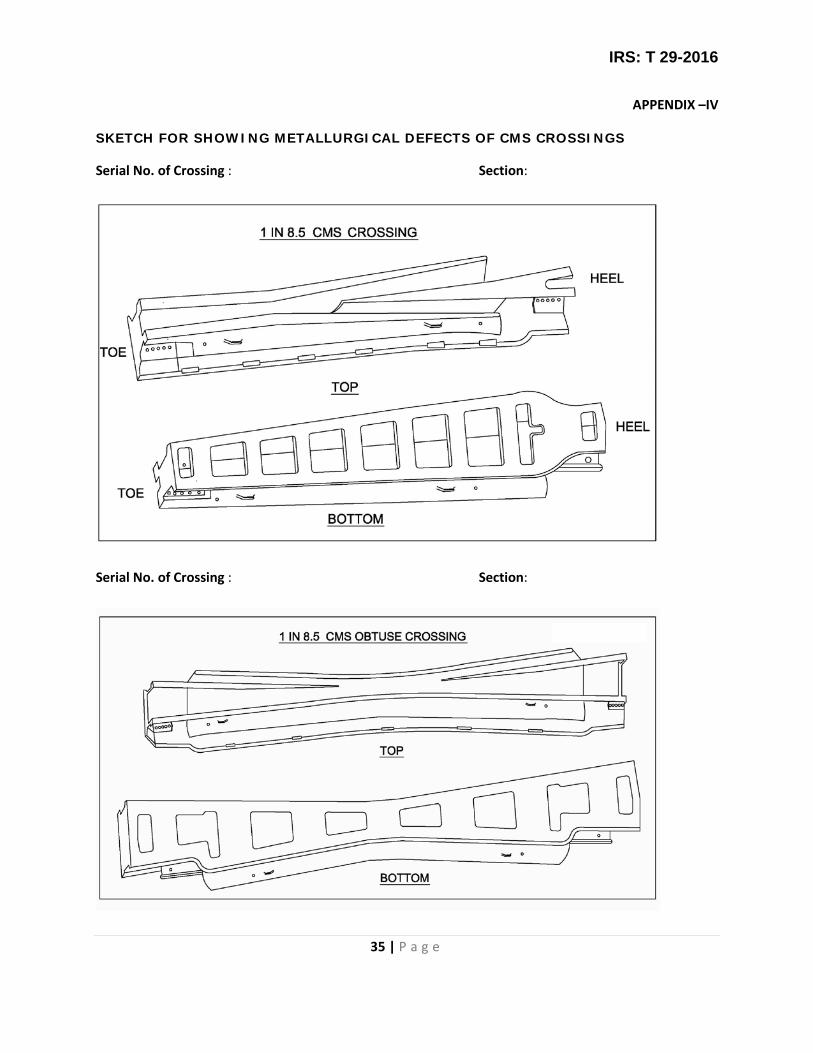
IRS: T 29-2016
35 | P a g e
APPENDIX –IV
SKETCH FOR SHOWING METALLURGICAL DEFECTS OF CMS CROSSINGS
Serial No. of Crossing : Section:
Serial No. of Crossing : Section:

IRS: T 29-2016
36 | P a g e
Serial No. of Crossing : Section:
Serial No. of Crossing : Section:
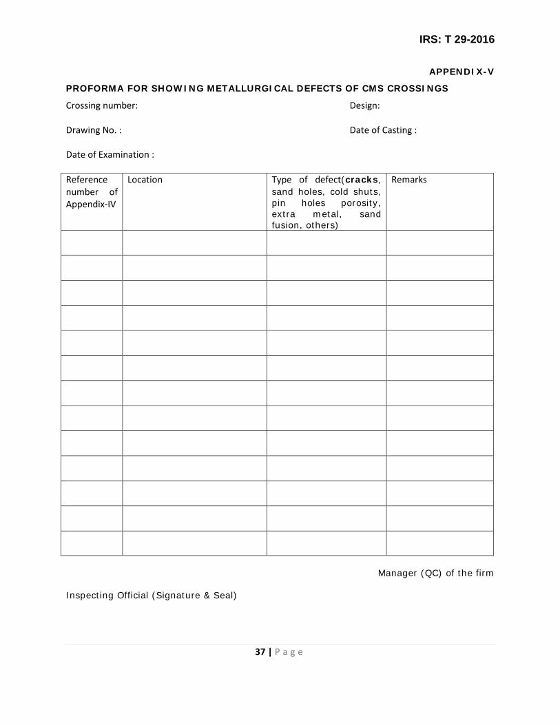
IRS: T 29-2016
37 | P a g e
APPENDIX-V
PROFORMA FOR SHOWING METALLURGICAL DEFECTS OF CMS CROSSINGS
Crossing number: Design:
Drawing No. : Date of Casting : Date of Examination :
Reference number of Appendix-IV
Location Type of defect(cracks, sand holes, cold shuts, pin holes porosity, extra metal, sand fusion, others)
Remarks
Manager (QC) of the firm
Inspecting Official (Signature & Seal)

IRS: T 29-2016
38 | P a g e
APPENDIX-VI
PROFORMA FOR DIMENSIONAL INSPECTION OF CAST MANGANESE STEEL CROSSING
1 Cast on serial number 2 Type and section with drawing number 3 Date of inspection 4 Heat number 5 Items to be inspected
5.1 Positions of crossing (Running surface up)
5.1.1 End fitments (both toe and heel end)
5.1.2 Alignment at the fish-plated joint matching etc.
5.1.3 Length
5.1.4 Wheel tread
5.1.5 Top edge contour
5.1.6 Offset (both toe end and heel end)
5.1.7 Flange well depth (including surface condition of flange well)
5.1.8 Flange way clearance
5.1.9 Overall alignment (including local misalignment)
5.1.10 Throat clearance Top surface level
5.1.11 Top surface level
5.1.12 Concavity/convexity/twist. If any
5.1.13 Wing rails
5.1.14 Nose thickness. 5.1.15 Nose depression
5.1.16 Height at different locations
5.1.17 Fish bolt holes
5.1.18 Fishing plane
5.1.19 Bond holes

IRS: T 29-2016
39 | P a g e
5.2 Position (Bottom up)
5.2.1 Bottom surface
5.2.2 Web thickness
5.2.3 Tie (thickness, width etc.)
5.2.4 Bottom width
5.2.5 Flange thickness (including thickness at recesss)
5.2.6 Roof thickness (i.e. below flange well, Vee portion etc.)
5.2.7 Condition of end section – faces (both heel and toe end)
5.3 Other items, if any
Manager (QC) of the Firm Inspecting official
Note: 1. Defect, if any, be marked on a sketch at appendix-IV 2. Marking of certain locations with chalk to be done on the crossing as desired by inspecting official to expedite inspection with the help of gauges/templates.

IRS: T 29-2016
40 | P a g e
APPENDIX-VII
SCHEMATIC DIAGRAM FOR IMPACT BEND TEST

IRS: T 29-2016
41 | P a g e
ARRANGEMENT FOR IMPACT BEND TEST

IRS: T 29-2016
42 | P a g e
APPENDIX-VIII
SKETCH SHOWING DIFFERENT CATEGORIES OF LOCATION TO BE CONSIDERED FOR REPAIR BY WELDING