Embed Size (px)
Citation preview
Guidance on the use of synthetic fibre ropes for marine energy devices
Deliverable 3.5.2 from the MERiFIC Project
A report prepared as part of the MERiFIC Project
"Marine Energy in Far Peripheral and Island Communities"
Ifremer reference: RDT CSM 13-232
September 2013
Written by:
Sam Weller ([email protected]), University of Exeter
Peter Davies ([email protected]), IFREMER
Lars Johanning ([email protected]), University of Exeter
Stephen Banfield ([email protected]), Tension Technology International, Ltd

2
MERiFIC was selected under the European Cross-Border Cooperation Programme
INTERREG IV A France (Channel) – England, co-funded by the ERDF.
The sole responsibility for the content of this report lies with the authors. It does not
represent the opinion of the European Communities. The European Commission is
not responsible for any use that may be made of the information contained therein.

MERiFIC Guidance on the use of synthetic fibre ropes for marine energy devices
3
Executive Summary
This report is a deliverable of MERiFIC Work Package 3: ‘Dynamic Behaviour of Marine
Energy Devices’ involving the collaboration of IFREMER (Institut français de recherche pour
l'exploitation de la mer) in France and the University of Exeter in the United Kingdom.
Although synthetic ropes have been used for the station-keeping of offshore structures for
the past two decades predominantly by the oil, gas and shipping industries, there is
considerable interest in their utilisation for the station-keeping of marine renewable energy
(MRE) devices. Differences in application between typically small, highly responsive
devices (e.g. Wave Energy Converters or WECs) and large slow-moving platforms
necessitate a unique approach to mooring system design and dedicated mooring
component test programs, both guided by relevant certification standards. It is the intention
of this report to provide an introduction to synthetic mooring ropes in the context of previous
usage in the offshore industry and also to highlight factors which should be considered for
their use in MRE mooring systems.
The document begins by setting the scene to give background on the fundamental
differences between previous applications of synthetic mooring ropes and MRE devices. In
Section 2 a brief overview of commercially available ropes is then given. The distinct
properties of synthetic materials and rope constructions are summarised with emphasis
placed on issues which are likely to be relevant for MRE devices. In the absence of specific
advice for this emerging industry, conventional approaches to applying safety factors to
synthetic ropes are then introduced. Section 3 highlights in-service considerations relevant
for the different lifecycle stages of ropes, from installation and operational procedures (such
as maintenance and inspection) to decommissioning. Specific modelling approaches for
synthetic ropes are then summarised in Section 4, followed by a summary in Section 5. This
document is not intended to be an exhaustive account of all aspects of synthetic mooring
ropes and in light of this further references are provided for the interested reader.

MERiFIC Guidance on the use of synthetic fibre ropes for marine energy devices
4
Contents
1 Background ...................................................................................................... 7
2 Design, Analysis and Usage Considerations ................................................. 9
2.1 Synthetic Ropes as Mooring Components .................................................... 9
2.2 Materials and Constructions ......................................................................... 10
2.3 End Terminations ........................................................................................... 13
2.4 Properties........................................................................................................ 13
2.4.1 Mass and Cost .......................................................................................... 13
2.4.2 Breaking Strength .................................................................................... 14
2.4.3 Viscoelastic and Viscoplastic Behaviour ............................................... 14
2.4.4 Axial Stiffness ........................................................................................... 15
2.4.5 Axial Damping .......................................................................................... 17
2.4.5.1 Forced Response ............................................................................. 17
2.4.5.2 Free Response ................................................................................. 17
2.4.6 Variation of Properties with Usage ......................................................... 18
2.4.6.1 Short-term Changes ........................................................................ 18
2.4.6.2 Long-term Changes ......................................................................... 19
2.5 Safety Factors ................................................................................................. 23
3 In-service Considerations.............................................................................. 27
3.1 Installation ...................................................................................................... 27
3.2 Maintenance and Inspection ......................................................................... 27
3.3 Decommissioning .......................................................................................... 30
4 Modelling Approaches for MRE Mooring Systems ..................................... 31
4.1 Numerical ........................................................................................................ 31
4.2 Experimental ................................................................................................... 32
5 Summary ......................................................................................................... 33
6 References ...................................................................................................... 34
MERiFIC Guidance on the use of synthetic fibre ropes for marine energy devices
5
Introduction
The MERiFIC Project
MERiFIC is an EU project linking Cornwall and Finistère through the ERDF INTERREG IVa
France (Manche) England programme. The project seeks to advance the adoption of
marine energy in Cornwall and Finistère, with particular focus on the island communities of
the Parc naturel marin d’Iroise and the Isles of Scilly. Project partners include Cornwall
Council, University of Exeter, University of Plymouth and Cornwall Marine Network from the
UK, and Conseil général du Finistère, Pôle Mer Bretagne, Technôpole Brest Iroise,
IFREMER and Bretagne Développement Innovation from France.
MERiFIC was launched on 13th September at the National Maritime Museum Cornwall and
runs until June 2014. During this time, the partners aim to
Develop and share a common understanding of existing marine energy resource
assessment techniques and terminology;
Identify significant marine energy resource ‘hot spots’ across the common area,
focussing on the island communities of the Isles of Scilly and Parc Naturel Marin
d’Iroise;
Define infrastructure issues and requirements for the deployment of marine energy
technologies between island and mainland communities;
Identify, share and implement best practice policies to encourage and support the
deployment of marine renewables;
Identify best practice case studies and opportunities for businesses across the two
regions to participate in supply chains for the marine energy sector;
Share best practices and trial new methods of stakeholder engagement, in order to
secure wider understanding and acceptance of the marine renewables agenda;
Develop and deliver a range of case studies, tool kits and resources that will assist
other regions.
To facilitate this, the project is broken down into a series of work packages:
WP1: Project Preparation WP2: Project Management WP3: Technology Support WP4: Policy Issues WP5: Sustainable Economic Development WP6: Stakeholder Engagement WP7: Communication and Dissemination
MERiFIC Guidance on the use of synthetic fibre ropes for marine energy devices
6
Disclaimer:
It is the intention of this document to provide introductory guidance for the use of synthetic
mooring ropes for marine renewable energy (MRE) applications. Readers are actively
encouraged to also seek guidance from certification agencies before embarking on the
specification of mooring components and the design of mooring systems. The authors of
this document cannot be held liable for any damage, loss or injury resulting from use of
these guidelines.
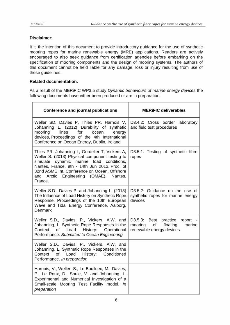
Related documentation:
As a result of the MERiFIC WP3.5 study Dynamic behaviours of marine energy devices the
following documents have either been produced or are in preparation:
Conference and journal publications MERiFIC deliverables
Weller SD, Davies P, Thies PR, Harnois V, Johanning L. (2012) Durability of synthetic mooring lines for ocean energy devices, Proceedings of the 4th International Conference on Ocean Energy, Dublin, Ireland
D3.4.2: Cross border laboratory and field test procedures
Thies PR, Johanning L, Gordelier T, Vickers A, Weller S. (2013) Physical component testing to simulate dynamic marine load conditions, Nantes, France, 9th - 14th Jun 2013, Proc. of 32nd ASME Int. Conference on Ocean, Offshore and Arctic Engineering (OMAE), Nantes, France.
D3.5.1: Testing of synthetic fibre ropes
Weller S.D., Davies P. and Johanning L. (2013) The Influence of Load History on Synthetic Rope Response. Proceedings of the 10th European Wave and Tidal Energy Conference, Aalborg, Denmark
D3.5.2: Guidance on the use of synthetic ropes for marine energy devices
Weller S.D., Davies, P., Vickers, A.W. and Johanning, L. Synthetic Rope Responses in the Context of Load History: Operational Performance. Submitted to Ocean Engineering
D3.5.3: Best practice report - mooring of floating marine renewable energy devices
Weller S.D., Davies, P., Vickers, A.W. and Johanning, L. Synthetic Rope Responses in the Context of Load History: Conditioned Performance. In preparation
Harnois, V., Weller, S., Le Boulluec, M., Davies,
P., Le Roux, D., Soule, V. and Johanning, L.
Experimental and Numerical Investigation of a
Small-scale Mooring Test Facility model. In
preparation

MERiFIC Guidance on the use of synthetic fibre ropes for marine energy devices
7
1 Background
Over the last two decades synthetic fibre mooring ropes have been utilised by the oil and
gas industry for the station keeping of offshore equipment and platforms. The shift away
from conventional technologies (i.e. chains and wire ropes) has been driven by the need to
specify economical mooring systems that are sufficiently robust to withstand mooring loads
of equipment moored in deep and ultra-deep water locations. Compared to existing mooring
components, synthetic ropes have particular advantages, including low cost and mass (per
unit length) and load-extension properties that can be harnessed to reduce peak loadings
[1]. Their adoption is also driven by examples of fatigue failure and wear of steel
components [2]. Extensive operational experience has been acquired from the application
of these materials for subsea mooring components and hawsers in a wide range of
environments across the globe. This coupled with laboratory test programmes to determine
the operational and fatigue performance of components has shaped offshore guidelines
such as those produced by the Det Norske Veritas (DNV-OS-E301 and DNV-OS-E303
[3,4]), Bureau Veritas (NI432DTOR01E [5]), American Bureau of Shipping [6], International
Standards Organisation (ISO18692:2007 and ISO/TS14909:2012 [7,8]) and American
Petroleum Institute (APIRP2SM [9]).
Based on the accumulated knowledge of an established offshore rope industry, marine
renewable energy (MRE) device developers are keen to utilise the inherent properties of
synthetic ropes for the mooring systems of their devices. Unfortunately it is not a
straightforward matter to apply existing offshore guidelines or practices to this emerging
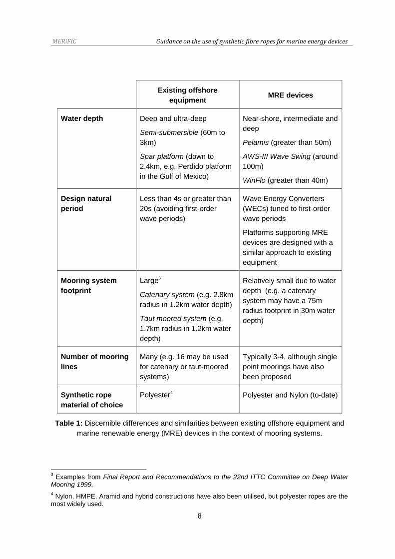
industry due to fundamental differences, such as those listed in Table 1. This disparity is the
subject of on-going work within the MERiFIC 3.5 work package Dynamic behaviours of
marine energy devices1 [10-12]. One caveat to this generalisation is that similarities will
exist for MRE devices which are based on large floating platforms (i.e. semi-submersible,
tension leg platform: TLP or spar floater geometries) for floating wind turbines and multi-
purpose projects.
Whilst the design of a floating MRE device will depend on the mode of operation2, in general
devices which are small compared to the incident wave length will dynamically respond to
first-order and second-order (low frequency) wave loading as well as the combined effects
of wind and currents. The loads experienced by an MRE mooring system will therefore be
heavily influenced by the motions of the device to the extent that the response of the
mooring system and device are closely coupled [14-16]. Conversely the mooring system of
a large floating platform will have the primary function of station keeping whilst allowing low
frequency motions (within permissible, small amplitude limits). Hence although a degree of
commonality exists between the two areas of application (i.e. mooring system types), the
loads experienced by the mooring system will clearly differ, necessitating a new approach to
MRE mooring system design and analysis.
1 Highlighted in MERiFIC deliverable D3.5.1: Testing of synthetic fibre ropes
2 For example wave energy converters (WECs) are typically classified using terms such as point
absorber, attenuator and terminator [13]
MERiFIC Guidance on the use of synthetic fibre ropes for marine energy devices
8
Existing offshore
equipment MRE devices
Water depth Deep and ultra-deep
Semi-submersible (60m to
3km)
Spar platform (down to
2.4km, e.g. Perdido platform
in the Gulf of Mexico)
Near-shore, intermediate and
deep
Pelamis (greater than 50m)
AWS-III Wave Swing (around
100m)
WinFlo (greater than 40m)
Design natural
period
Less than 4s or greater than
20s (avoiding first-order
wave periods)
Wave Energy Converters
(WECs) tuned to first-order
wave periods
Platforms supporting MRE
devices are designed with a
similar approach to existing
equipment
Mooring system
footprint
Large3
Catenary system (e.g. 2.8km
radius in 1.2km water depth)
Taut moored system (e.g.
1.7km radius in 1.2km water
depth)
Relatively small due to water
depth (e.g. a catenary
system may have a 75m
radius footprint in 30m water
depth)
Number of mooring
lines
Many (e.g. 16 may be used
for catenary or taut-moored
systems)
Typically 3-4, although single
point moorings have also
been proposed
Synthetic rope
material of choice
Polyester4 Polyester and Nylon (to-date)
Table 1: Discernible differences and similarities between existing offshore equipment and
marine renewable energy (MRE) devices in the context of mooring systems.
3 Examples from Final Report and Recommendations to the 22nd ITTC Committee on Deep Water
Mooring 1999.
4 Nylon, HMPE, Aramid and hybrid constructions have also been utilised, but polyester ropes are the
most widely used.

MERiFIC Guidance on the use of synthetic fibre ropes for marine energy devices
9
2 Design, Analysis and Usage Considerations
2.1 Synthetic Ropes as Mooring Components
A catenary system is the most likely choice for the station keeping of small buoy-like MRE
equipment (Figure 1). Synthetic ropes tend to be used for the mid or upper sections (i.e.
from the fairlead). These materials are usually buoyant in water, therefore in order to
provide sufficient horizontal and vertical restoring forces at the fairlead(s), chains are used
for the lower sections which are connected to anchors. Utilising chains for the lower
mooring line sections also prevents the synthetic rope(s) from coming into contact with the
seabed, which would over time result in wear through abrasion.
A taut moored system differs from a catenary system in that the restoring forces are a result
of axial stretching rather than geometric changes of the complete mooring system. This type
of system, which comprises one or more synthetic ropes, may be used to moor a stable
platform in locations with small tidal ranges (e.g. a floating platform to support tidal energy
devices). Alternatively synthetic ropes can be used to provide a compliant link between the
power take-off unit and buoy of a WEC (i.e. the Carnegie Wave Energy’s CETO device5).
Figure 1: Schematic of (left) taut-moored and (right) catenary mooring systems showing
possible MRE device mooring arrangements comprising synthetic ropes and chains (blue
and black lines respectively)
Other mooring geometry layouts, including the use of auxiliary buoys, or interconnected
systems for arrays of devices are possible. Further guidance on the design and analysis of
mooring systems can be found in the MERiFIC deliverable D3.5.3 Best practice report -
mooring of floating marine renewable energy devices.
5 http://www.carnegiewave.com/ (accessed online: 09/09/2013).

MERiFIC Guidance on the use of synthetic fibre ropes for marine energy devices
10
2.2 Materials and Constructions
Ropes used in the offshore environment can be made from a wide range of natural and
synthetic organic fibres, with materials such as cotton, flax, hemp and sisal used since the
early days of sail. The focus of this document is on commercially available rope materials
which are likely to be adopted by MRE developers based on their usage in the offshore
industry. Materials which are used commercially include:
Nylon (Polyamide or PA) Liquid crystal polymers (LCPs)
Polyester (PET) Hybrid materials
Polypropylene (PP) Polyolefins (i.e. HMPE or HPPE)
High-modulus, high-tenacity fibres
(i.e. Aramid)
Material Density
(g/cm3)
Melting
/charring
point (°C)
Moisture
(%)6
Modulus
(N/tex,
GPa)
Tenacity
(mN/tex)
Strength
(MPa)
Break
extension
(%)
Hemp
Steel
HMPE
Aramid
PET
PP
PA6(7)
1.5
7.85
0.97
1.45
1.38
0.91
1.14
~150
1600
150
500
258
165
218
8
0
0
1-7
<1
0
5
21.7, 32.6
20, 160
100, 100
60, 90
11, 15
7, 6
7(6), 8(8)
470
330
3500
2000
820
620
840(6)
705
2600
3400
2900
1130
560
960
1.8
2(9)
3.5
3.5
12
20
20
Table 2: Selected properties of several synthetic fibre materials (values from [17]). Steel
and the natural fibre hemp are included for reference
For comparative purposes, material properties are listed in Table 2 and of this list, particular
materials are more likely to be used for MRE mooring systems. Nylon and polyester are the
most commonly used rope materials for applications which require moderately high strength
and ductility. Polypropylene has similar elasticity to these materials but poor cyclic loading
characteristics and can be affected by changes in temperature. Natural fibres such as flax
and hemp possess similar strengths to nylon and polyester but synthetic materials are
favoured as their performance is more predictable in demanding applications including the
effects of weathering [17]. Materials such as high modulus polyethylene (HMPE), high
performance polyethylene (HPPE), liquid crystal polymer (LCP) and aramid have
considerably higher breaking strengths which are comparable to steel and are stiffer than
nylon and polyester. The combined high strength and low mass of these materials makes
6 At 65% rh and 20°C.
7 PA6.6 has a higher melting point (258°C) than PA6.
8 The modulus and strength of nylon is approximately 15% lower when wet [17].
9 Yield point of steel.

MERiFIC Guidance on the use of synthetic fibre ropes for marine energy devices
11
them an attractive choice for taut-moored applications as an alternative for steel wires [18].
The combination of several polymers (i.e. through copolymerisation or co-extrusion) to
obtain desirable performance characteristics has received some attention, such as the
combined extrusion of polypropylene and polyethylene, or polypropylene and polyester melt
mixes, but few commercially available examples exist.
Due to their favourable properties and previous use in offshore applications nylon and
polyester are two materials which are likely to be used for MRE mooring ropes. The
properties of these materials depend on the behaviour of molecule bonds which vary when
subjected to heat (and humidity in the case of nylon). In typical offshore operating
conditions the flexibility of nylon is provided by free rotation of carbon bonds in amorphous
regions of the structure. Saturation of the rope will result in increased mobility of hydrogen
bonds in the amorphous regions, leading to a reliance on the crystallite regions for structural
integrity. Although nylon has good temperature and abrasion resistance when dry, both
these characteristics reduce once saturated (i.e. there is typically a 15% strength reduction
when wet [17]). Comparatively the structure (and hence strength) of polyester is unaffected
by water ingress unless at elevated temperatures, (i.e. similarly to nylon the crystallite
structures begin to melt above 260°C [17]). Whilst in offshore applications ambient
temperatures of this magnitude are unlikely (unless the rope is in close proximity with an
extreme heat source), localised internal temperature rises are possible due to hysteresis
heating.
Material Ductility Strength
(Wet/Dry)
Resistance
UV Temperature Abrasion10 Creep Tension/compression
fatigue
HMPE
Aramid
PET
PP
PA6
LCP
Table 3: Indicative properties of several synthetic rope materials11, classified by colour as
, and . Actual performance will depend on the rope construction and
application.
The basic elements of a rope are shown in Figure 2. Most ropes have a hierarchal
construction comprising repeating assemblies, sub-assemblies and elements. In the case of
the nylon rope shown in Figure 2, the parallel-stranded construction comprises 7x subropes
each comprising 3x strands. Each strand is made up of 8x rope yarns and each rope yarn is
made up of several hundred spun nylon fibres or filaments. Fibres are therefore the smallest
element used in ropes, each of which can range in diameter from 10 to 50µm for multi-
filament yarns or 0.2 to 0.5mm for monofilament yarns [17]. All of the hierarchal levels are
10
Nylon has good abrasion resistance when dry but poor resistance when wet.
11 Indicative properties from [1,17] and author experience.
poor average good

MERiFIC Guidance on the use of synthetic fibre ropes for marine energy devices
12
assembled with a helical twist or braid angle. Laid and braided constructions with high twist
angles are suited for general purpose use, with plaited and single braid constructions
typically comprising 8x to 12x strands (Figure 3). These and double braided constructions
are commonly used for mooring applications since they do not twist when loaded and are
straightforward to splice. Low helical angle ropes tend to be used for high load applications
which comprise multiple sub-ropes or braided assemblies inside a protective braided jacket.
Parallel yarn or filament constructions have also been manufactured which are torque
balanced to minimise twisting during loading. Hybrid rope constructions can be divided into
two categories:
Hybrid construction techniques, e.g. a braid-on-braid outer with parallel subrope
core, or differing lay lengths throughout the structure
Mixed material constructions, which have a similar purpose to co-extruded or
copolymerised constructions but the rope elements are made from different
materials (i.e. fibres or yarns)
Figure 2: (left) Typical rope construction hierarchy (image adapted from [19]) and (right)
Nylon parallel-stranded rope used in MERiFIC WP3.5
Figure 3: Examples of rope constructions; (left) schematic of Lankhorst GAMA 98® deep
water rope with multiple subropes and outer jacket, (top right) schematic of Bexco double-
braid rope with outer jacket and (bottom right) Lankhorst TIPTO®EIGHT 8-strand plaited
rope12
12
Images from Lankhorst and Bexco product literature (accessed online: 10/09/2013).
Rope or subrope

MERiFIC Guidance on the use of synthetic fibre ropes for marine energy devices
13
2.3 End Terminations
The ends of ropes are usually terminated with eye splices, providing an attachment point for
shackles and other hardware. Although many ropes have a protective jacket (such as the
one studied in the MERiFIC WP3.5), an additional sheath made from hard-wearing material
(Figure 4) or a metal eye provides extra protection against wear from connecting hardware.
In the case of nylon ropes, direct contact between steel components and load-bearing fibres
would not be advisable due to the possibility of material degradation occurring from
abrasion and rust contamination. Splicing is usually carried out by the rope manufacturer to
specified eye-to-eye rope lengths. The process is highly skilled because the splice must be
made such that the applied load is distributed evenly to each of the load bearing
components of the rope.
2.4 Properties
A brief overview of rope properties is included in this section and for more detailed insight
the reader is referred to more comprehensive texts such as the Handbook of Fibre Rope
Technology [17]. Further information regarding synthetic rope testing procedures, relevant
guidelines and test facilities can be found in the MERiFIC deliverable D3.5.1 Testing of
synthetic fibre ropes.
2.4.1 Mass and Cost
Synthetic ropes have a very low density in comparison to steel mooring components (Table
2). Due to their low mass per unit length mooring ropes are usually partially buoyant13 in sea
and fresh water even after saturation and are therefore considerably easier to handle than
steel components. Assuming that a rope with equivalent strength characteristics can be
found for the application, the direct replacement of chain sections with synthetic ropes will
result in lower pre-tensions at the device fairleads. It is therefore possible that the use of
synthetic ropes can therefore reduce the load bearing requirements of the moored structure.
One key advantage of synthetic fibre ropes over chains and wires is their relatively low cost.
Ridge et al. in [1] carried out comparative cost and mass analysis of several single-line
catenary and taut-moored arrangements including several different anchor configurations.
The comparison highlighted the advantages in using lightweight, but durable mooring
components to replace conventional mooring chains. For example, the ability of nylon to
reduce peak loadings would allow smaller gauge mooring chain to be used in anchor-chain-
surface buoy-rope-device configurations. The study notes that by adopting this design the
overall mass of this system could be to be reduced by 88kg/m and the cost by over £90K
per mooring line. These reductions would partly be attributable to the specification of lower
capacity components, such as anchors. Clearly in practice the feasibility of using a
particular mooring system and actual cost savings that are achieved will depend on the
case in question. However, cost savings are potentially scalable to multiple devices in array
or ‘farm’ layouts.
13
Of the main materials used, nylon is negatively buoyant, whereas polyethylene and polypropylene are positively buoyant.

MERiFIC Guidance on the use of synthetic fibre ropes for marine energy devices
14
2.4.2 Breaking Strength
Breaking strength is defined as the ability to withstand increased loading until a sufficient
number of fibres have been damaged that total failure of the rope will occur with continued
loading. The load at which this occurs is often quoted by rope manufacturers as the
minimum break load (MBL) and will depend not only on the applied load rate but also the
condition of the rope. In terms of strength, the rope that is selected will depend on the
expected extreme loads of the mooring system and required safety factor (see Section 2.5).
The DNV-OS-E301 Position Mooring guidelines [3] define the strength (Sc) of steel wire,
chain and synthetic components based on the mean value of breaking strength (µs) and the
coefficient of variation of breaking strength (δs):
( )
With δs typically less than 0.10. When µs and δs have been quantified from a component
testing program, the statistical uncertainty of obtained values depends on the number of
tests (n) performed. In this instance, a modified value of component strength is calculated:
(
)
The reader is directed to the DNV-OS-E301 Position Mooring guidelines [3] and associated literature for further information regarding testing procedures, including the MERiFIC deliverable D3.5.1: Testing of synthetic fibre ropes.
Figure 4: The inevitable result of a load-to-failure test of a new nylon mooring rope sample
(test conducted at IFREMER as part of the MERiFIC WP3.5 study)
2.4.3 Viscoelastic and Viscoplastic Behaviour
Under constant load, synthetic materials tend to extend or creep (Figure 5). The extension
of the material may be recoverable (i.e. viscoelastic behaviour) or permanent (viscoplastic)
and this will depend on the applied load conditions and condition of the rope. Both creep

MERiFIC Guidance on the use of synthetic fibre ropes for marine energy devices
15
and recovery can either occur immediately or be delayed [19]. If a newly manufactured
rope is loaded for the first time, constructional rearrangement of the rope will also result in
permanent extension, which can be thought of as a ratchet. It is for this reason that tension-
tension testing programmes used to determine the operational and fatigue properties of
ropes typically commence with a number of creep and relaxation cycles to allow
constructional rearrangement to occur enabling the rope to be tested at a known initial
state. This stage is often referred to as ‘bedding-in’. Even after bedding-in, the rope
construction may permit extension in the form of recoverable twisting. In addition to dynamic
loading, an important consideration for mooring system design and testing is the level of
expected creep in-service. It is possible that non-recoverable extension of the rope will
result in a significantly different mooring geometry and lower pre-tension. Unless the
mooring lines are subsequently re-tensioned the station keeping abilities of the mooring
system will be reduced, resulting in a potentially damaging change to the dynamics of the
moored device, particularly for taut-moored systems [18]. In extreme cases creep failure
may occur at loads lower than the minimum break load of the rope.
Figure 5: Load-extension behaviour of a new Nylon mooring rope sample subjected to 10
cycles of bedding-in at IFREMER (part of the MERiFIC WP3.5 study)
2.4.4 Axial Stiffness
As mentioned in the previous section the load-extension behaviour of synthetic ropes can
be attributed to both material and constructional changes. The ability to absorb tensile
energy and elongate to a far greater level than more rigid components (i.e. steel chains and
wires) is favourable as the magnitude of peak loads will be lower than if rigid components
were used. For comparative purposes, the specific stress-elongation properties of a range
of synthetic rope materials are shown in Figure 6. It is clear from this graph that nylon and
polyester are capable of large compliance compared to stiffer materials such as steel and
aramid, with nylon fibres capable of extensions between 15-20% before failure. In
assembled rope form, greater extensions may be possible due to rearrangement of the rope
structure under loading. Another key point is that unlike rigid materials, such as metals
which tend to display a linear load-extension relationship in their elastic phase (i.e. Hooke’s
Creep
Permanent elongation
Recovery

MERiFIC Guidance on the use of synthetic fibre ropes for marine energy devices
16
law), the viscoelastic phase of synthetic materials is highly non-linear, particularly for
polyester and nylon.
Figure 6: Specific stress-extension curves for various synthetic fibres; aramid, steel, nylon
or polyamide (PA), polyester (PES), high strength carbon (Carbon-HS), high strength
fibreglass (S-Glass) and gel spun high modulus polyethylene (HPPE). Note: tex is a
measure of mass per unit length (g/km) [17]
Figure 7: Load-strain response (blue line) of a new nylon rope sample subjected to
harmonic loading as part of the MERiFIC WP3.5 study. A single degree-of-freedom line
fitted to the response is shown as a dashed black line
Offshore guidelines dictate that the average axial stiffness of the rope (defined as EA, units:
kN) is determined after repeated harmonic loading and calculated from the gradient of a line
fitted to maximum and minimum load and strain values. An alternative approach (reported in
[10]) which appears to result in closer agreement, is to fit a single degree-of-freedom trend
line to measured values (e.g. Figure 7).

MERiFIC Guidance on the use of synthetic fibre ropes for marine energy devices
17
Note that bending stiffness is not covered in these guidelines but may be relevant for lines
which are subjected to significant different motions at each end, or are routed via hawse or
winches. In this case, guidelines covering bend-over-sheave testing should be consulted.
2.4.5 Axial Damping
2.4.5.1 Forced Response
Viscoelastic materials demonstrate hysteresis, where there is a delay (or phase difference)
between changes to the applied load and resulting extension or recovery. This is perhaps
best illustrated through considering one load-extension loop of a nylon rope sample
subjected to harmonic loading (Figure 8). The energy expended during loading and
unloading can be estimated from the area contained within the loop (further details can be
found in [10-12]). The energy absorbed and dissipated is related to the damped response of
the rope (defined as damping rate B, units: kNs/m), which will contribute to the overall
damped response of the moored system.
Figure 8: Load-extension response (blue line) of a new nylon rope sample subjected to
harmonic loading as part of the MERiFIC WP3.5 study. The area enclosed within the
hysteresis loop (green region) can be used to estimate the damped behaviour of the rope
Drag damping resulting from the motion of the line through the water not mentioned in these
guidelines but information regarding aspects of numerical modelling is given in the MERiFIC
deliverable D3.5.3 Best practice report - mooring of floating marine renewable energy
devices.
2.4.5.2 Free Response
Resonant responses tend to be avoided in structural design to avoid the effects of load
amplification14. Synthetic ropes and steel wires, particularly those used in taut-moored
applications may be subjected to vortex induced vibration (VIV) and vortex induced motions
14
Often quantified as Dynamic Amplification Factors (DAFs).

MERiFIC Guidance on the use of synthetic fibre ropes for marine energy devices
18
(VIM) induced by turbulence shedding in current flows. High frequency cyclic loading may
have implications for the fatigue life of mooring components. Guidance is provided in the
DNV-OS-E301 Position Mooring guideline [3] to determine the response of mooring lines
using rigid body assumptions. However, because no information is provided in [3] or the
DNV-OS-E303 Offshore Fibre Ropes guideline [4] on how to quantify the natural period of
synthetic ropes, a short investigation was carried out as part of the MERiFIC WP3.5 study
at IFREMER. On the basis that the free response of a rope subjected to an impulse load
can be used to determine the damping behaviour of the rope, tests were conducted on an
aged rope sample (Figure 9). With one end of the rope supported by an overhead crane
and load cell, a 3kN mass at the lower end was used to provide a pre-tension. A small mass
(10.7kg) was then dropped onto the large mass to induce a decay response which was
recorded by the load cell (sample rate: 10kHz). Repeated tests indicated a natural period of
approximately 0.2s15, significantly different from the response of the crane without the rope
in place (natural period: 0.07s). Assuming that the rope is oscillating in a single degree-of-
freedom, the natural period and applied load can be used to approximate the spring
stiffness. For the aged rope sample this was found to equal 276.8kN/m (note different units
from axial stiffness: EA).
Figure 9: Axial natural period tests conducted at IFREMER as part of the MERiFIC WP3.5
study; (left) experimental set-up, (right) filtered load cell response after impulse excitation
2.4.6 Variation of Properties with Usage
2.4.6.1 Short-term Changes
If a synthetic mooring rope is subjected to many hundreds or thousands of identical
harmonic load cycles then the performance of the rope will eventually reach a steady-
state16. The standardised approach to determine the average stiffness of the rope is to use
the final 5-10 cycles of steady-state response. Prior to reaching a steady-state, the
response of the rope will be transient and the evolution of strain (e.g. Figure 10) is related to
15
Natural periods and spring stiffness values were also calculated for a higher pre-tension level; 5kN (0.3s and 268.8kN/m respectively).
16 Continued loading will eventually lead to failure through fatigue.

MERiFIC Guidance on the use of synthetic fibre ropes for marine energy devices
19
the changing properties of the rope17. The mooring system of a dynamically response MRE
is unlikely to experience repeated harmonic loading unless it is in a deep water location and
very long period swell waves are a common occurrence. Furthermore, steady loading
around the pre-tension level of the system will only occur in calm conditions. As a direct
result of the stochastic nature of ocean waves, mooring loads for dynamically response
equipment tend to be highly irregular and of varying amplitude, phase and mean load
(which is partially influenced by the tide). The instantaneous properties of the rope will
depend not only on the applied load history, but also the level of strain achieved [10-12]. In
order to accurately predict synthetic rope performance and longevity, it is therefore essential
that synthetic ropes are specified in the context of loading regimes relevant to the
application, rather than just relying on existing standards.
Figure 10: Time-variation of strain of a new Nylon mooring rope sample used in the
MERiFIC WP3.5 study using the Dynamic Marine Component (DMaC) facility at the
University of Exeter [11]
2.4.6.2 Long-term Changes
A variety of factors will affect the performance of a rope over its lifetime. Investigations
conducted as part of the MERiFIC WP3.5 study have compared the performance of new
and aged rope samples. The aged rope sample was extracted from a 20m mooring line
used during the first 18 month deployment of the South West Mooring Test Facility
(SWMTF, further details can be found in [10-12,20,21). Clear differences in performance
were observed when the samples were subjected to the same load-time series comprising
harmonic loading intervals as well as two irregular time-series based on mooring tensions
measured by the SWMTF. Increased compliance and hence strain of the recovered
SWMTF rope (Figure 11) indicate mild damage sustained during the first deployment. This
damage is likely to be the result of fatigue cycling coupled with a few extreme events (i.e.
17
For the tests conducted on nylon samples as part of this study, axial stiffness appears to increase and damping reduce with continued loading [10,11].

MERiFIC Guidance on the use of synthetic fibre ropes for marine energy devices
20
the last irregular interval shown in Figure 11). Scanning Electron Microscope (SEM) images
of fibres support this idea, with wear recesses, caused by fibre-on-fibre friction, present in
aged fibres (Figure 12).
Figure 11: Time-variation of strain of a new (green) and aged (black) nylon mooring rope
samples subjected to the same load time-series as part of the MERiFIC WP3.5 study [12]
Figure 12: SEM images of (left) new and (right) aged fibres (analysis conducted at
IFREMER [12])
The possibility of failure occurring through repeated, cyclic loading is particularly relevant for
synthetic mooring lines operating in highly dynamic environments (i.e. WECs). Fatigue life
calculations are typically based on the application of many thousands of harmonic load
cycles to ropes or sub-ropes with several different load amplitudes and mean load levels,
for example the Oil Companies International Marine Forum (OCIMF) Thousand cycle load
level (TCLL) test procedure for single point mooring hawsers [22,23] (example loads are
listed in Table 4). As the main fatigue failure mechanism is wear resulting from friction

MERiFIC Guidance on the use of synthetic fibre ropes for marine energy devices
21
between adjacent yarns, yarn-on-yarn cyclic tests until failure are also carried out to
determine the effectiveness of friction-reducing marine finishes.
Stage Cumulative load sequence Equivalent high
load levels 1000 cycles
at 50% NWBS
1000 cycles
at 60% NWBS
1000 cycles
at 70% NWBS
1 X 251 cycles at 60%
2 X X 215 cycles at 70%
3 X X X 113 cycles at 80%
Table 4: Thousand cycle load level (TCLL) test procedure (from [22]). Load levels are in
respect of the average wet break strength (NWBS) of the rope
Whilst the standardised approach of fatigue calculation [3,4] may be applicable for the
mooring systems of large, slow moving equipment it is clearly questionable for mooring
lines subjected to loads which are highly variable in amplitude and duration. Therefore as
with the pertinent need to determine the operational performance of synthetic ropes using
loading regimes which are relevant to MRE devices, existing fatigue testing practices must
be altered to suit this new application perhaps through the use of accelerated testing. The
published work carried out to-date suggests very promising fatigue performance for certain
synthetic ropes (Figure 13).
Figure 13: Fatigue results for several mooring components (from Ridge et al. [1]). Dashed
lines indicate extrapolated values

MERiFIC Guidance on the use of synthetic fibre ropes for marine energy devices
22
The ingress of fine grit, debris or living species into the rope structure will accelerate fibre-
on-fibre friction wear and this can even occur if the rope is covered in a protective jacket
(Figure 14). To mitigate particulate ingress, particular rope manufacturers include filtration
screens to block particles larger than 1 micron. Whilst plant-based bio-fouling is unlikely to
cause damage to unjacketed synthetic fibres, a build-up of hard-shelled species such as
barnacles, mussels and limpets may result in fibre cutting or abrasion.
The hysteresis response of viscoelastic materials results in heating of the rope as energy is
dissipated through the structure [24]. Heat can also be generated by slip occurring between
fibres. In extreme cases when the rate of heat transfer is not sufficiently high, localised
melting and peeling of the fibre surfaces can occur [25], weakening the structure of the rope
and providing a rough surface which will induce wear. Even moderate changes in
temperature are likely to change the properties of the fibre materials at a local level [26] and
clearly in the context of the energetic responses which may be experienced by MRE
mooring systems this topic requires further investigation.
Figure 14: Juvenile mussel shells found on the inside of the projective jacket of the aged
rope sample used for the MERiFIC WP3.5 study
Exposure of the outer surface of the rope to ultraviolet (UV) light will lead to material
degradation over time, demonstrated through brittle and discoloured fibres which are
weaker than their internal counterparts. Polypropylene is particularly susceptible to
prolonged UV exposure. For subsea lines, the level of exposure decreases with depth. A
non-load bearing protective jacket will prevent exposure as long as it remains intact. Lines
which are partially submerged or subjected to continuous salt spray and soaking from
waves will experience wetting and drying cycles. As mentioned in Section 2.2 the strength
properties of nylon alter with both moisture content and temperature. Fatigue performance
will also be influenced, as demonstrated for nylon 6.6 fibres by Kenney, M.C. et al. [27]. Salt
crystals which remain after drying are likely to be an abrasive medium between contacting
fibres.

MERiFIC Guidance on the use of synthetic fibre ropes for marine energy devices
23
Steady Cyclic Infrequent
Creep Fatigue/friction Exceedance of the MBL
UV exposure Heating Heating
Wetting/drying Compression fatigue
UV exposure Shock loading
Table 5: A summary of possible damage mechanisms. Further information on these
mechanisms is available in the literature (e.g. [17,28])
If the motions of the device are highly dynamic then it is probable that the mooring
components will experience shock or snatch loading. Rapidly changing loads may be large
in amplitude, ranging from slack (i.e. close to zero tension) to peak load to low load in very
short intervals. Although the compliant properties of synthetic ropes are suited to reducing
the magnitude of peak loadings, it is possible that rapidly applied loads will result in
permanent elongation (i.e. the ratchet analogy introduced in Section 2.4.3) and localised
rapid heating which could result in damage. During low loads it is possible that fibres, yarns
or strands may buckle resulting in fatigue concentrations if the hinges of the kink flex
regularly. This is referred to as axial compression fatigue and the occurrence of buckling will
depend on the rope construction and loading conditions. In general the fibres of stiffer
materials such as aramids or HMPE will fail more readily than more compliant materials
such as polyester if the buckled areas are flexed.
2.5 Safety Factors
When specifying a synthetic rope it is important that a factor of safety is specified which
reflects the expected environmental and loading conditions that the rope will experience
during its lifetime. In the absence of explicit guidelines, safety factors for MRE mooring
equipment are currently based on existing certification guidelines which are necessarily high
based on the risks associated with catastrophic failure of oil and gas exploration equipment
(i.e. the mooring failure of the Argyll Transworld 58 in 1981 [2]). The consequences of
mooring component failure of a MRE device will depend on its location, proximity to other
equipment or water-users, whether it is manned18 and if redundancy has been built into the
system19. Generally the impact of component failure will be considerably less than oil or gas
exploration equipment (which may result in loss of life or environmental disaster) even if
station keeping ability has been lost. The application of existing guidelines may therefore be
18
For MRE devices this will only be the case during installation, maintenance and recovery operations which would be conducted during favourable weather windows (i.e. during calm conditions); hence the percentage of time that a device will be manned will be extremely small.
19 Higher safety factors must be used for systems which do not have redundancy.

MERiFIC Guidance on the use of synthetic fibre ropes for marine energy devices
24
unnecessarily onerous and costly and a new approach is needed which reflects the
fundamentally different requirements and features of MRE mooring systems20.
At present there is a lack of specific guidance for the use of synthetic ropes with MRE
devices, for example the DNV guideline DNV-OSS-213 Certification of Tidal and Wave
Energy Converters [29] refers to the broader DNV-OS-E301 Position Mooring guideline [3].
Safety factors for synthetic ropes do not feature in the DNV-OS-E303 Offshore Fibre Ropes
guideline [4], but are contained within [3]. In this document only the elements of [3] relevant
to synthetic fibre ropes are reported.
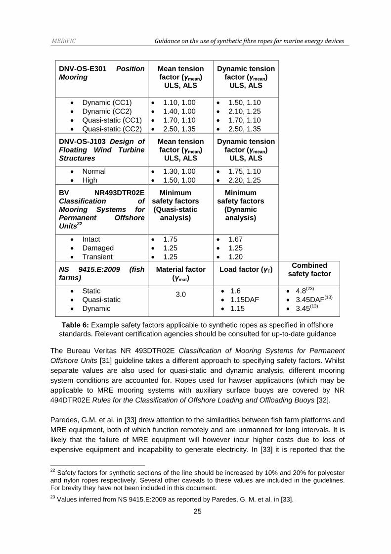
In the DNV-OS-E301 Position Mooring guidelines safety factors are classified based on the
consequence of mooring system failure; Class 1: “Where mooring system failure is unlikely
to lead to unacceptable consequences such as loss of life, collision with an adjacent
platform, uncontrolled outflow of oil or gas, capsize or sinking” and Class 2: “Where mooring
system failure may well lead to unacceptable consequences of these types.” The required
strength of mooring components21 (Sc) for Ultimate Limit State (ULS) and Accident Limit
State (ALS) scenarios is calculated using the following equation based on mean and
dynamic loadings (Tc-mean and Tc-dyn). Related safety factors are listed in Table 6:
When characteristic strengths are not available, Sc is determined from the minimum break
strength of new components (Sc = 0.95Smbs). The same approach is effectively taken in the
recently published DNV-OS-J103: Design of Floating Wind Turbine Structures guideline [30]
which contains further information about selecting dynamic and mean tensions based on 50
year values. In this guideline different consequence class terms are defined (Normal and
High), which appear to be equivalent to Classes 1 and 2 in [3] (although it should be noted
that this is not explicitly stated). It is interesting to note that whilst the ALS mean and
dynamic safety factors for the floating wind turbine guidance are the same as in [3], the ULS
safety factors are between values in [3] recommended for dynamic and quasi-static
analysis. This may be indicative of the conservative approach being taken to floating wind
turbine design at present. Separate guidance for the characteristic tensile capacity of
tendons used in taut-moored applications is given in [30].
20
For example, the requirements of a mooring system for a floating wind turbine will differ from a resonantly operating WEC, especially if multiple devices are to be deployed in array or ‘farm’ layouts
21 The statistical uncertainty of strength characteristics based on test statistics has to be accounted
for [3].
MERiFIC Guidance on the use of synthetic fibre ropes for marine energy devices
25
DNV-OS-E301 Position Mooring
Mean tension factor (γmean)
ULS, ALS
Dynamic tension factor (γmean)
ULS, ALS
Dynamic (CC1)
Dynamic (CC2)
Quasi-static (CC1)
Quasi-static (CC2)
1.10, 1.00
1.40, 1.00
1.70, 1.10
2.50, 1.35
1.50, 1.10
2.10, 1.25
1.70, 1.10
2.50, 1.35
DNV-OS-J103 Design of Floating Wind Turbine Structures
Mean tension factor (γmean)
ULS, ALS
Dynamic tension factor (γmean)
ULS, ALS
Normal
High
1.30, 1.00
1.50, 1.00
1.75, 1.10
2.20, 1.25
BV NR493DTR02E Classification of Mooring Systems for Permanent Offshore Units22
Minimum safety factors (Quasi-static
analysis)
Minimum safety factors
(Dynamic analysis)
Intact
Damaged
Transient
1.75
1.25
1.25
1.67
1.25
1.20
NS 9415.E:2009 (fish farms)
Material factor (γmat)
Load factor (γT) Combined
safety factor
Static
Quasi-static
Dynamic
3.0 1.6
1.15DAF
1.15
4.8(23)
3.45DAF(13)
3.45(13)
Table 6: Example safety factors applicable to synthetic ropes as specified in offshore
standards. Relevant certification agencies should be consulted for up-to-date guidance
The Bureau Veritas NR 493DTR02E Classification of Mooring Systems for Permanent
Offshore Units [31] guideline takes a different approach to specifying safety factors. Whilst
separate values are also used for quasi-static and dynamic analysis, different mooring
system conditions are accounted for. Ropes used for hawser applications (which may be
applicable to MRE mooring systems with auxiliary surface buoys are covered by NR
494DTR02E Rules for the Classification of Offshore Loading and Offloading Buoys [32].
Paredes, G.M. et al. in [33] drew attention to the similarities between fish farm platforms and
MRE equipment, both of which function remotely and are unmanned for long intervals. It is
likely that the failure of MRE equipment will however incur higher costs due to loss of
expensive equipment and incapability to generate electricity. In [33] it is reported that the
22
Safety factors for synthetic sections of the line should be increased by 10% and 20% for polyester and nylon ropes respectively. Several other caveats to these values are included in the guidelines. For brevity they have not been included in this document.
23 Values inferred from NS 9415.E:2009 as reported by Paredes, G. M. et al. in [33].
MERiFIC Guidance on the use of synthetic fibre ropes for marine energy devices
26
Norwegian NS 9415.E:2009 guidelines for fish farms use a simpler partial coefficient
method which does not distinguish between mean and dynamic tensions. In the following
expression material and load factors (γmat and γT respectively) are used in conjunction with
the expected tension (Tc) and strength of the component (S):
For synthetic materials a material factor of 3.0 is specified24 in NS 9415.E:2009. When
conducting quasi-static analysis a dynamic amplification factor (DAF) greater than one (and
typically at least 1.1) is used. As mentioned in Section 2.4.6.2 the fatigue performance of
synthetic ropes subjected to cyclic loading must be determined in order to accurately
estimate the long-term durability of these components. In addition to the ultimate and
accident limit states, the DNV-OS-E301 Position Mooring and DNV-OS-J103 Design of
Floating Wind Turbine Structures guidelines [3,30] use a fatigue limit state (FLS) to
calculate accumulated damage incurred through fatigue load cycling.
For synthetic ropes a slightly different approach to determining fatigue capacity is adopted.
Instead of S-N (stress-number of cycles) curves, the ratio of tension range to characteristic
strength (R) to number of cycles is used for tension-tension cycling:
( ( )) ( ) ( )
Example gradient and intercept parameters for the R-N curve of polyester rope are given in
the guidelines as aD = 0.259 and m = 13.46. A similar approach is also adopted in the
Bureau Veritas Classification of Mooring Systems for Permanent Offshore Units guidelines
[31]. The fatigue life of other synthetic rope materials can be found in the literature, for
example in Ridge et al. [1] and the American Petroleum Institute guidelines [9]. For fatigue
design a single safety factor is specified in the DNV-OS-E301 Position Mooring guidelines
[3]:
Where dc is the characteristic fatigue damage accumulated during the design life as a result
of cyclic loading. A fatigue safety factor of γF = 60 is specified for polyester which is
considerably higher than what is used for steel components (usually between 1 and 10) due
to the apparent large variability of fatigue test results and the typically larger exponent (m)
on the R-N curve. Lower fatigue life factors are permissible if fibre rope segments are
replaced on a routine basis. Further discussion regarding offshore certification guidelines
features in the MERiFIC deliverable D3.5.3 Mooring of floating marine renewable energy
devices, including commentary on the forthcoming IEC TC114 IEC/TS 62600-10 Ed. 1.0
guidelines [34].
24
For reference, the material factor of new chains and chain components is 2.0, increasing to 5.0 for used chains [3]

MERiFIC Guidance on the use of synthetic fibre ropes for marine energy devices
27
3 In-service Considerations
Estimates of synthetic rope performance and life expectancy determined from numerical
modelling and physical testing are valid only if correct in-service procedures are followed. In
this section several generic considerations are proposed to aid planning of installation,
maintenance and decommissioning procedures.
3.1 Installation
To avoid damage during storage prior to installation, synthetic ropes should be stored in a
suitable location avoiding prolonged exposure to extremes of temperature, UV light and
degrading chemical agents as well as damage from auxiliary equipment. Care should be
exercised during handling to minimise or avoid damage to the surface, either through cuts
or abrasion. This is more of an issue with unjacketed ropes.
The installation procedure for the entire mooring system will be planned prior to the
deployment date and should include contingency for unexpected events (i.e. sudden
changes in weather and the failure of equipment). The installation of synthetic ropes will
either be part of an entire mooring system installation or be a recovery/replacement
procedure as mentioned in the next section. Due to their prior in the offshore industry, it is
sensible to utilise existing installation guidelines, even if the scale of installation differs. For
example, the Floating production system JIP FPS mooring integrity report produced by
Noble Denton Europe Limited in 2006 includes practical advice on polyester rope
installation [2]. Following installation it may be prudent to perform bedding-in loading on
each mooring line to settle the rope structure, perhaps utilising the installation vessel.
Bedding-in of the rope will clearly be more difficult to perform at sea in comparison with the
laboratory environment, but will mean that the mooring lines will not have to be re-tensioned
in-service (if the MRE device has this capability25). Additionally for mooring systems which
utilise drag anchors, bedding-in could form part of the anchor embedment process. If
bedding-in is not carried out during installation, then structural rearrangement of the rope
may occur in-service, leading to a change in the stiffness and station keeping abilities of the
mooring system [35].
3.2 Maintenance and Inspection
Access to subsea mooring lines will be considerably more difficult than for surface lines
between devices and/or auxiliary buoys. Larger maintenance and detailed inspection
procedures require the recovery of mooring lines onto the deck of the work boat utilising
crane and winch equipment. For catenary mooring systems it may be possible to inspect
the ropes without disturbing the anchors if there is sufficient slack in the mooring line and
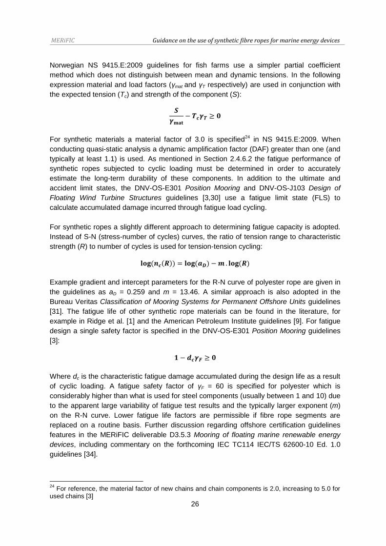
favourable tidal conditions (an example operation is illustrated in Figure 15). For a taut-
25
Chain jacks are used on Floating Production, Storage and Offloading (FPSO) vessels. For MRE devices without chain jacks, line re-tensioning may be possible by shortening sections of chain. Alternatively, self re-tensioning may be built into the system (i.e. lazy-wave mooring configurations, see MERiFIC deliverable D3.5.3: Best practice report - mooring of floating marine renewable energy devices).
MERiFIC Guidance on the use of synthetic fibre ropes for marine energy devices
28
moored system a dive team would be required in addition to a work boat for rope recovery.
Clearly large operations such as these require significant expenditure, favourable weather
windows and available equipment. It is therefore sensible that such operations are
combined with other maintenance procedures. A potentially lower cost alternative is the
scheduling of visual inspections using divers and/or remote operated underwater vehicle
(ROV) equipment. These operations will only give the condition of the rope surface and
terminations (i.e. wear through abrasion, chaffing and cutting, as well as degradation due to
UV exposure) and therefore internal damage may be obscured by bio-fouling during long
deployments. Measures to prevent bio-fouling have been successfully tried, for example the
use of polyurethane as a rope coating (Figure 16).
Figure 15: Example operation showing recovery of one SWMTF mooring rope using on-
board crane and winch of the work boat
As yet an in-situ inspection technique to determine internal damage or the condition of
terminations and splices does not exist. This is particularly an issue for jacketed ropes.
Removal of the jacket to inspect the internal rope components is not advisable unless
protective measures can be reinstated afterwards. Efforts have been made to gain insight
into changes to the structural integrity of polyester ropes through the use of short sections
of rope (or ‘inserts’) as part of the mooring limbs of floating platforms (e.g. [36,37]), with
periodic removal (i.e. every 2.5 years) for laboratory testing. In the mid-1990s Petrobras
was the first to use this technique for mobile offshore drilling units and production facilities
and more recently the use of inserts has been required for particular locations (i.e. in the
Gulf of Mexico [36]). However, the effectiveness of this approach to determining the
condition of permanent mooring systems has been questioned [37] and it is not clear how
relevant separate inserts would be for MRE mooring systems located in considerably
shallower water depths. Instead, it would be more feasible for ropes to be recovered in their
entirety and tested as part of an on-going monitoring program, with the data yielded used to
inform the development of numerical modelling tools.

MERiFIC Guidance on the use of synthetic fibre ropes for marine energy devices
29
Wear, fatigue UV exposure Bio-
fouling
Creep Shock-
loading
Axial
compression
Check Cuts and chaffing,
broken or pulled
fibres may give a
fuzzy appearance,
rope compaction,
localised melting.
Damage to
splices/terminations
Brittleness
and
discolouration
of outer fibres
for
unjacketed
ropes
Significant
bio-
fouling26
In the absence
of in-situ
elongation
measurements
a significant
change in pre-
tension may
indicate creep
Usually not
discernible
from visual
inspection,
hence check
load
measurements
Bulges may
appear in
ropes with a
tight jacket.
Damaged
fibres will
have a kinked
or ‘Z’-shaped
appearance
or be
severed.
Action Replacement may
be necessary if
damage is
excessive.
Consider removing
rope and testing in
the laboratory
Sample fibres
to be
removed for
tension-
testing
Periodic
removal
of growth
may be
necessary
to avoid
change of
system
dynamics
Re-tensioning
may be
necessary due
to change in
mooring
system
dynamics.
Excessive
creep will
necessitate
rope
replacement
Line to be
replaced if
tension or
expected
damage is
excessive.
Line to be
replaced if
tension-
tension
testing
indicates
unacceptable
strength
reduction
Table 7: Example considerations for a generic inspection and maintenance program as part
of condition management. Further guidance is given in [38-40]
Neither the DNV-OS-E301 nor the DNV-OS-E303 guidelines [3,4] contain a great amount of
detail on inspection apart from emphasising the need for a documented condition
management program. More detailed information can be found in the DNV-RP-E304
Damage assessment of fibre ropes for offshore mooring guideline [38]. For synthetic ropes
used in MRE mooring applications, inspection and replacement intervals will depend on the
material used and loading conditions experienced. The International Guideline CI 2001-04
Fiber Rope Inspection and Retirement Criteria [39] comprises a comprehensive summary of
fatigue and damage mechanisms as well as inspection procedures. It is likely that a
conservative approach will be taken initially based on reliability predictions and lifecycle
26
The effects of bio-fouling on synthetic rope performance will depend on the rope construction, species and level of growth (the latter two of these factors are location dependent). Particular species may be invasive even for jacketed ropes (see Section 2.4.6.2). Significant growth will affect the dynamics of the system due to the increased inertia (submerged and added mass) as well as drag of the mooring line. Further work is therefore required to define the limits of bio-fouling which are acceptable in the context of MRE devices and if preventative measures should be taken (Figure 16).

MERiFIC Guidance on the use of synthetic fibre ropes for marine energy devices
30
analysis, the accuracy of which could be improved by the measurement of mooring loads
and environmental conditions. In the absence of specific guidance, Table 7 lists particular
considerations which may be applicable for synthetic mooring ropes used in MRE
applications.
Figure 16: (left) Recovered nylon mooring rope used during the first deployment of
SWMTF. Considerable bio-fouling in the form of mussel growth and kelp can be observed,
(middle) removal of fouling using the on-board crane. (right) An example of bio-fouling
prevention; polyurethane coated polyester riser protection net after four years of service on
the Heidrun TLP.
3.3 Decommissioning
Due to the irreparable damage occurred in-service, ropes which have reached the end of
their usable life must be disposed of properly. The DNV-OS-303 guidelines specify that fibre
ropes should be taken out of service if loads exceeding 70% MBL have been measured [4]
with more general guidance given in [39]. A similar approach is adopted for lifting equipment
to avoid the possibility of accidental usage. Synthetic ropes are comparably lower in cost
compared to steel components, but that should not encourage an irresponsible attitude to
disposal at the end of their service life. Recycling programs such as the one launched by
Lankhorst Ropes in March 2011 are part of a ‘cradle-to-grave’ approach to rope
manufacture. Whilst the processed granulate is a sellable commodity (the Lankhorst Ropes
program cites several potential applications such as landing stages, bollards, bridges and
picnic sets), the reasons why this is not carried out on a wider scale by other rope
manufacturers are two-fold: a) there are a large number of offshore ropes in-service which
have yet to be retired and b) the recycling process is not straightforward due to issues with
contamination.

MERiFIC Guidance on the use of synthetic fibre ropes for marine energy devices
31
4 Modelling Approaches for MRE Mooring Systems
4.1 Numerical
Numerical modelling approaches can be split into two key areas; i) synthetic rope modelling
tools and ii) mooring system software.
Several approaches have been taken to model the various aspects of synthetic fibre rope
performance, for example the creep of HMPE [18] and the heat build-up [24,26] and
cumulative damage of polyester [40]. These studies have either been based on the
development of theoretical curves utilising coefficients based on experimental
measurements (e.g. [41]) or the development of complex modelling tools using
viscoelastic/plastic formulae, finite element and continuum methods (e.g. [42-44]). Fibre
Rope Modeller (FRM) developed by Tension Technology International (TTI) is a
commercially available modelling program based on early work by Leech et al. [45]. The
program uses yarn properties to predict the performance of ropes in terms of extension,
torque and twist27 by adopting a hierarchal calculation approach. The program is also
capable of predicting the effects of cycling and certain damage mechanisms (i.e. creep,
hysteresis, abrasion and fatigue) on long-term rope durability. Whilst FRM has primarily
been used to model large mooring ropes for deep water offshore applications (e.g. [19]), the
application of this program for MRE mooring systems is a recent occurrence.
There are several commercial programs which are available to carry out static, quasi-static
and dynamic analysis of complete mooring systems, including (but not limited to) Orcaflex
by Orcina28, Optimoor by TTI29 and Deeplines by Principia30. TTI have also produced an
online Rope Selection Calculator31 and formulae which can be used in the initial stages of
mooring system design. Examples of commercially available simulation software designed
specifically for MRE devices are few, (e.g. for WECs there is WaveDyn by GL Garrad
Hassan32). An introduction to mooring system software is not given here, but features in the
MERiFIC deliverable D3.5.3 Best practice report - mooring of floating marine renewable
energy devices. It is mentioned in this section to highlight the current disparity between
detailed synthetic rope modelling approaches and mooring system software. It is typical in
the currently available mooring system software for the stiffness and damping properties of
elements of the mooring line (whether they are synthetic ropes, cables or chain) to be
specified by single values. Some programs allow the specification of non-linear load-strain
properties, but even this does not take into account the possible change in stiffness (or
27
For twisted rope constructions.
28 http://www.orcina.com/SoftwareProducts/OrcaFlex/ (accessed online: 05/10/2013).
29 http://www.tensiontech.com/software/optimoor.html (accessed online: 05/10/2013).
30 http://www.principia.fr/expertise-fields-software-products-deeplines-126.html (accessed online:
05/10/2013).
31 http://www.tensiontech.com/tools_guides/rope_selection_calculator.php (accessed online:
05/10/2013).
32 http://www.gl-garradhassan.com/en/software/25900.php (accessed online: 05/10/2013).

MERiFIC Guidance on the use of synthetic fibre ropes for marine energy devices
32
damping) that is typical of synthetic ropes with usage and conditioning [10-12]. It is
therefore important that sensitivity of the moored system to changes in both stiffness and
damping is determined during the analysis stage of mooring system design.
4.2 Experimental
MRE device concepts are typically tested using reduced scale models in wave and/or
current flumes, with the selected model scale governed by scaling criterion and the physical
dimensions of available facilities. A Froude scaling regime is usually adopted for the
representative dimensional and dynamic quantities of components and assemblies. For
small-scale modelling of mooring cables and chains, the two most important criteria to
satisfy are the correct submerged mass and geometry of each mooring system element in
order for the inertia and drag of the line to be representative. Single or multiple axial springs
are often used to achieve the correct axial stiffness33 of the mooring line [46]. It is possible
that the non-linear axial stiffness of a synthetic mooring line can be achieved using multiple
springs, however a more prudent approach may be to use the same material from which the
rope is constructed to also give a more accurate representation of material damping. As far
as the authors are aware this approach has only been attempted twice, once to represent
polyester mooring ropes [47] and once as part of this MERiFIC work package for nylon
mooring ropes. In the MERiFIC study, 1:5 scale model tests of the SWMTF were conducted
in IFREMER’s salt water wave basin with small-scale representations of new and bio-fouled
lines comprising nylon rope yarns (Figure 17, further details can be found in [48]). Previous
tension-tension tests on the nylon yarns indicated that they gave a good representation of
the full-scale rope axial stiffness through Froude scaling. The results of this experimental
study will feature in a forthcoming publication [49] which will include comparison to
simulations carried out using Orcaflex.
Figure 17: (left) 1:5 scale model of the SWMTF tested in the salt water basin at IFREMER,
(right) underwater view of small-scale lines with representative bio-fouling [48].
33
Bending stiffness will need to be considered for umbilical cables and may also need to be considered for MRE devices undergoing highly dynamic motions

MERiFIC Guidance on the use of synthetic fibre ropes for marine energy devices
33
5 Summary
It has been the intention of this document to give background information on synthetic fibre
ropes which may be used for MRE mooring system design. Whilst the short and long-term
performance of these materials is more complex than conventional ferrous materials used in
mooring applications, there are distinct advantages to using synthetic ropes instead of steel
components including low cost, low mass and an inherent ability to absorb energy. It is
possible that they are an enabling technology in the design of economic mooring systems.
Although used in a wide range of offshore applications for the past two decades, this new
application has unique challenges and detailed investigations will be required before
widespread adoption and certification can be achieved.
At the time of writing (October 2013) guidelines which are relevant to synthetic mooring
ropes for MRE devices have yet to be published by the main offshore certification agencies.
Instead device developers must use existing guidelines which were written for other
offshore applications and hence the relevance of such information is at least questionable, if
not inappropriate. Due to the relatively recent application of synthetic ropes for MRE
devices, there are a number of uncertainties about the performance and reliability of these
ropes operating in conditions which (of the few examples which have been deployed to-
date) are highly specific to the application. It is perhaps unsurprising that the current
approach is very conservative; using large factors of safety and specifying standard rope
materials and constructions.
Figure 18: MRE device examples which utilise synthetic mooring ropes; (from left) WinFlo
concept (source: WinFlo), CETO wave energy device (source: Carnegie Wave Energy) and
CORES oscillating water column [50]. Images accessed online: 21/09/2013
Over time more devices will be deployed and a greater insight will be gained into the
durability of synthetic ropes in this new application, with mooring loads measured in-service
used to inform laboratory test programmes as well as reliability and lifecycle analysis. As
confidence is increased more suitable factors of safety can be applied to MRE mooring
components, which can take into account the distinct differences between unmanned MRE
equipment and safety critical equipment used in other offshore applications (i.e. by the oil
and gas industry). It is encouraging that there are already several examples of MRE devices
which have used (i.e. in sea-trials) or are planning to use synthetic fibre ropes, such as
WinFlo, CETO and the CORES project (Figure 18).

MERiFIC Guidance on the use of synthetic fibre ropes for marine energy devices
34
6 References
[1] Ridge, I.M.L., Banfield, S.J. and Mackay, J. (2010). Nylon Fibre Rope Moorings for Wave
Energy Converters. In Proceedings of the OCEANS 2010 conference, Seattle, USA
[2] Noble Denton Europe Limited (2006) Floating production system JIP FPS mooring
integrity. Research Report 444 prepared for the Health & Safety Executive
[3] Det Norske Veritas (2010). DNV-OS-E301: Position Mooring
[4] Det Norske Veritas (2013). DNV-OS-E303: Offshore Fibre Ropes
[5] Bureau Veritas, (2007). Certification of fibre ropes for deepwater offshore services. 2nd
edition. NI 432 DTO R01E
[6] American Bureau of Shipping (1999) Guidance notes on the application of synthetic
ropes for offshore mooring
[7] International Standards Organisation (2007) Fibre ropes for offshore stationkeeping:
Polyester. ISO18692:2007
[8] International Standards Organisation (2012) Fibre ropes for offshore stationkeeping:
High modulus polyethylene (HMPE). ISO/TS14909:2012
[9] American Petroleum Institute (2001) API RP 2SM: Recommended Practice for Design,
Manufacture, Installation, and Maintenance of Synthetic Fiber Ropes for Offshore Mooring
[10] Weller S.D., Davies P. and Johanning L. (2013) The Influence of Load History on
Synthetic Rope Response. Proceedings of the 10th European Wave and Tidal Energy
Conference, Aalborg, Denmark
[11] Weller S.D., Davies, P., Vickers, A.W. and Johanning, L. (TBD) Synthetic Rope
Responses in the Context of Load History: Operational Performance. Submitted to Ocean
Engineering
[12] Weller S.D., Davies, P., Vickers, A.W. and Johanning, L. (TBD) Synthetic Rope
Responses in the Context of Load History: Conditioned Performance. In preparation
[13] Harris, R.E., Johanning, L. and Wolfram, J. (2004) Mooring systems for wave energy
converters: A review of design issues and choices. 3rd International Conference on Marine
Renewable Energy, Blyth, UK
[14] Johanning, L. and Smith, G.H. and Wolfram, J. (2007) Measurements of static and
dynamic mooring line damping and their importance for floating WEC devices. Ocean
Engineering (2007), 1918-1934
[15] Fitzgerald, J. and Bergdahl, L. (2008) Including moorings in the assessment of a
generic offshore wave energy converter: A frequency domain approach. Marine Structures,
23-46
MERiFIC Guidance on the use of synthetic fibre ropes for marine energy devices
35
[16] Cerveira, F., Fonseca, N. and Pascoal, R. (2013) Mooring System Influence on the
Efficiency of Wave Energy Converters. Proceedings of the 10th European Wave and Tidal
Energy Conference, Aalborg, Denmark
[17] McKenna, H.A., Hearle, J.W.S. and O’Hear, N. (2004) Handbook of Fibre Rope
Technology. Woodhead Publishing Limited
[18] da Costa Mattos, H.S. and Chimisso, F.E.G. (2010) Modelling creep tests in HMPE
fibres used in ultra-deep-sea mooring ropes. International Journal of Solids and Structures
48 (2011) 144–152
[19] Flory, J.F., Banfield, S.J. and Petruska, D.J. (2004) Defining, Measuring, and
Calculating the Properties of Fibre Rope Deepwater Mooring Lines. Proceedings of the
2004 Offshore Technology Conference, Houston, USA. OTC 16151
[20] Weller, S. Davies, P. Thies, P.R., Harnois, V. and Johanning, L. (2012) Durability of
synthetic mooring lines for ocean energy devices. Proceedings of the 4th ICOE, Dublin,
Ireland
[21] Johanning, L. Thies, P. and Smith, G. (2010) Component test facilities for marine
renewable energy converters. Proceedings of the Marine Renewable and Offshore Wind
Energy Conference, London, UK
[22] OCIMF (2000) Oil Companies International Marine Forum) Guidelines for the
purchasing and testing of SPM hawsers
[23] Flory, J.F. (2000) The revised OCIMF SPM hawser guidelines. Proceedings of
OCEANS 2000 MTS/IEEE Conference, Providence, USA
[24] Bosman, R.L.M. (1996) On the Origin of Heat Build-up in Polyester Ropes.
Proceedings of the 1996 MTS/IEEE Oceans Conference. Fort Lauderdale, USA. 332-338
[25] Flory, J.F., Leech, C.M., Banfield, S.J. and Petruska, D.J. (2005) Computer Model to
Predict Long-Term Performance of Fiber Rope Mooring Lines. Proceedings of the 2005
Offshore Technology Conference, Houston, USA. OTC17592
[26] Overington, M.S. and Leech, C.M. (1997) Modelling Heat Buildup In Large Polyester
Ropes. International Journal of Offshore and Polar Engineering 7, 1, March 1997
[27] Kenney, M.C., Mandell, F.J. and McGarry, F.J. (1985) The effects of salt water and
concentrated salt solutions on the fatigue of nylon 6,6 fibres. Journal of Materials Science
20 (1985), 2060-2070
[28] Backer, S., McGarry, F.J. and Williams, J.H. (1981) Deterioration of Synthetic Fiber
Rope During Service. Report A131684
[29] Det Norske Veritas (2012). DNV-OSS-213: Certification of Tidal and Wave Energy
Converters
[30] Det Norske Veritas (2013). DNV-OS-J103: Design of Floating Wind Turbine Structures
MERiFIC Guidance on the use of synthetic fibre ropes for marine energy devices
36
[31] Bureau Veritas (2012) Classification of Mooring Systems for Permanent Offshore Units.
NR 493DTR02E
[32] Bureau Veritas (2006) Rules for the Classification of Offshore Loading and Offloading
Buoys NR 494DTR02E
[33] Paredes, G. M., Bergdahl, L., Palm, J., Eskilsson, C. and Pinto, F.T. (2013) Station
keeping design for floating wave energy devices compared to offshore oil and gas
platforms. Proceedings of the 10th European Wave and Tidal Energy Conference, Aalborg,
Denmark
[34] IEC/TS (2013) Marine energy - Wave, tidal and other water current converters - Part
10: The assessment of mooring system for marine energy converters (MECs). IEC/TS
62600-10 Ed. 1.0 In preparation
[35] Foulhoux, L., Pennec, S., Damy, G. and Davies, P. (1999) Testing of a large diameter
polyester rope offshore west Africa. Proceedings of the International Offshore and Polar
Engineering Conference, Brest, France
[36] Otten, J.D. and Leite, S. (2013) Thunder Hawk Mooring Rope Particle Ingress, Break,
and Fatigue Testing. Proceedings of the 2013 Offshore Technology Conference, Houston,
USA. OTC24080
[37] Tension Technology International & Stress Engineering Services (2004) Effective Use
of Inserts in a Mooring Line Rope Integrity Management System “INSERT JIP”
[38] Det Norske Veritas (2005). DNV-RP-E304: Damage Assessment of Fibre Ropes for
Offshore Mooring
[39] Cordage Institute (2001) International Guideline CI 2001-04 Fiber Rope Inspection and
Retirement Criteria Guidelines to Enhance Durability and the Safer Use of Rope. CI 2001-
04 First Edition
[40] Steckel, M.G. (1984) Tensile fatigue behaviour of polyester yarns in ambient and sea
water environments. MS thesis, Massachusetts Institute of Technology
[41] François, M., Davies, P., Grosjean, F., Legerstee, F. (2010) Modelling of fibre rope
load-elongation properties - Polyester and other fibres. Proceedings of the 2010 Offshore
Technology Conference, Houston, USA. OTC 20846
[42] Chailleux, E., Davies, P. (2003) Modelling the Non-Linear Viscoelastic and Viscoplastic
Behaviour of Aramid Fibre Yarns. Mechanics of Time-Dependent Materials 7, 291–303
[43] Davies, P., Lacotte, N., Kibsgaard, G., Craig, R., Cannell, R., Francois, S., Lodeho, O.,
Konate, K., Mills, S., Francois, M., Defoy, A-L., Durville, D., Vu, D., Gilmore, J. and
Sherman, D. (2013) Bend over sheave durability of fibre ropes for deep sea handling
operations. Proceedings of the 32nd International Conference on Offshore Mechanics and
Arctic Engineering, Nantes, France

MERiFIC Guidance on the use of synthetic fibre ropes for marine energy devices
37
[44] Ghoreishi, S.R., Cartraud, P., Davies, P. and Messager, T. (2007) Analytical modeling
of synthetic fiber ropes subjected to axial loads. Part I: A new continuum model for
multilayered fibrous structures. International Journal of Solids and Structures 44 (2007)
2924–2942
[45] Leech, C.M., Hearle, J.W.S., Overington, M.S., Banfield, S.J. (1993) Modelling tension
and torque properties of fibre ropes and splices. Proceedings of the Third International
Offshore and Polar Engineering Conference Singapore
[46] Cozijn, J.L. and Bunnik, T.H.J. (2004) Coupled mooring analysis for deep water CALM
buoy. Proceedings of the 23rd International Conference on Offshore Mechanics and Arctic
Engineering, Vancouver, Canada
[47] Fernandes, A.C. and Rossi, R.R. (2002) On the model scaling of polyester mooring
lines for offshore applications. Proceedings of the 21st International Conference on Offshore
Mechanics and Arctic Engineering, Oslo, Norway
[48] Le Roux, D. and Le Boulluec, M. (2012) Etude d’un ancrage textile pour la bouée SWMTF destineé à l’analyse du comportement des systèmes houlo-moteurs. Projet de Mastère Spécialisé Energies Marines Renouvelables, ENSTA, Bretagne
[49] Harnois, V., Weller, S., Le Boulluec, M., Davies, P., Le Roux, D., Soule, V. and
Johanning, L. (TBD) Experimental and Numerical Investigation of a Small-scale Mooring
Test Facility model. In preparation
[50] CORES (2011) Components for Ocean Renewable Energy Systems: Final Publishable
Summary Report 213633