Embed Size (px)
Citation preview

Guidance for Retrofitting Vehicle Restraint Systems on the Single Carriageway National
Road Network
DN-REQ-03079
February 2017

TRANSPORT INFRASTRUCTURE IRELAND (TII) PUBLICATIONS
About TII
Transport Infrastructure Ireland (TII) is responsible for managing and improving the country’s national road and light rail networks.
About TII Publications
TII maintains an online suite of technical publications, which is managed through the TII Publications website. The contents of TII Publications is clearly split into ‘Standards’ and ‘Technical’ documentation. All documentation for implementation on TII schemes is collectively referred to as TII Publications (Standards), and all other documentation within the system is collectively referred to as TII Publications (Technical).
Document Attributes
Each document within TII Publications has a range of attributes associated with it, which allows for efficient access and retrieval of the document from the website. These attributes are also contained on the inside cover of each current document, for reference.
TII Publication Title Guidance for Retrofitting Vehicle Restraint Systems on the Single Carriageway National Road Network
TII Publication Number DN-REQ-03079
Activity Design (DN) Document Set Technical
Stream Road Equipment (REQ) Publication Date February 2017
Document Number
03079 Historical Reference
n/a
TII Publications Website
This document is part of the TII publications system all of which is available free of charge at http://www.tiipublications.ie. For more information on the TII Publications system or to access further TII Publications documentation, please refer to the TII Publications website.
TII Authorisation and Contact Details
This document has been authorised by the Director of Professional Services, Transport Infrastructure Ireland. For any further guidance on the TII Publications system, please contact the following:
Contact: Standards and Research Section, Transport Infrastructure Ireland
Postal Address: Parkgate Business Centre, Parkgate Street, Dublin 8, D08 DK10
Telephone: +353 1 646 3600
Email: [email protected]

TII Publications DN-REQ-03079 Guidance for Retrofitting Vehicle Restraint Systems on the Single Carriageway National Road Network
February 2017
Page i
TII Publications
Activity: Design (DN)
Stream: Road Equipment (REQ)
TII Publication Title: Guidance for Retrofitting Vehicle Restraint Systems on the Single Carriageway National Road Network
TII Publication Number: DN-REQ-03079
Publication Date: February 2017
Set: Technical
Contents
1. Introduction ................................................................................................................. 1
2. Definitions .................................................................................................................... 2
3. Process Overview ....................................................................................................... 4
4. Category A - Constrained locations .......................................................................... 8
5. Category B - Structures ............................................................................................ 17
6. Category C - Urban settings ..................................................................................... 28
....................................................................................................................... 36
VRS Condition Survey Template ......................................................................................... 36
....................................................................................................................... 39
Sample VRS Preliminary Design Report Summary Template ............................................. 39
....................................................................................................................... 49
VRS Preliminary Design Report Summary - Worked Examples .......................................... 49
....................................................................................................................... 63
Sample SAVeRS Input Data for VRS Life Cycle Cost Analysis ........................................... 63

TII Publications DN-REQ-03079 Guidance for Retrofitting Vehicle Restraint Systems on the Single Carriageway National Road Network
February 2017
Page ii
Contents Table
1. Introduction ................................................................................................................. 1 1.1 Scope and implementation ................................................................................. 1
2. Definitions .................................................................................................................... 2
3. Process Overview ....................................................................................................... 4 3.1 Site survey .......................................................................................................... 4
3.2 Overview of the preliminary design process ....................................................... 5
3.3 VRS Preliminary Design Report ......................................................................... 7
4. Category A - Constrained locations .......................................................................... 8 4.1 Potential site specific constraints ........................................................................ 8
4.2 Design process and flow chart .......................................................................... 10
4.3 Development of preferred design solutions ...................................................... 13
5. Category B - Structures ............................................................................................ 17 5.1 Potential constraints at structures ..................................................................... 17
5.2 Design process and flow chart .......................................................................... 20
5.3 Development of preferred design solutions ...................................................... 23
6. Category C - Urban settings ..................................................................................... 28
6.1 Potential issues in urban settings or speed limit zones ..................................... 28
6.2 Design process and flow chart .......................................................................... 29
6.3 Development of preferred design solutions ...................................................... 33
....................................................................................................................... 36
VRS Condition Survey Template ......................................................................................... 36
....................................................................................................................... 39
Sample VRS Preliminary Design Report Summary Template ............................................. 39
....................................................................................................................... 49
VRS Preliminary Design Report Summary - Worked Examples .......................................... 49
....................................................................................................................... 63
Sample SAVeRS Input Data for VRS Life Cycle Cost Analysis ........................................... 63
TII Publications DN-REQ-03079 Guidance for Retrofitting Vehicle Restraint Systems on the Single Carriageway National Road Network
February 2017
Page 1
1. Introduction
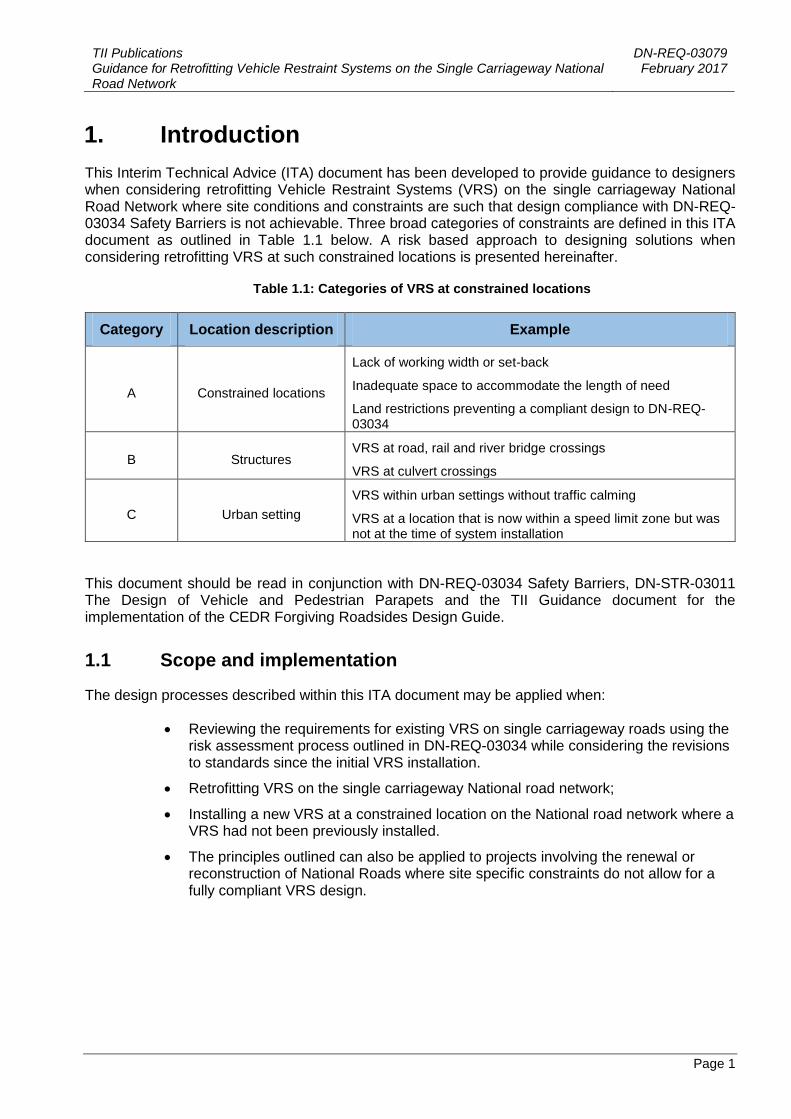
This Interim Technical Advice (ITA) document has been developed to provide guidance to designers when considering retrofitting Vehicle Restraint Systems (VRS) on the single carriageway National Road Network where site conditions and constraints are such that design compliance with DN-REQ-03034 Safety Barriers is not achievable. Three broad categories of constraints are defined in this ITA document as outlined in Table 1.1 below. A risk based approach to designing solutions when considering retrofitting VRS at such constrained locations is presented hereinafter.
Table 1.1: Categories of VRS at constrained locations
Category Location description Example
A Constrained locations
Lack of working width or set-back
Inadequate space to accommodate the length of need
Land restrictions preventing a compliant design to DN-REQ-03034
B Structures VRS at road, rail and river bridge crossings
VRS at culvert crossings
C Urban setting
VRS within urban settings without traffic calming
VRS at a location that is now within a speed limit zone but was not at the time of system installation
This document should be read in conjunction with DN-REQ-03034 Safety Barriers, DN-STR-03011 The Design of Vehicle and Pedestrian Parapets and the TII Guidance document for the implementation of the CEDR Forgiving Roadsides Design Guide.
1.1 Scope and implementation
The design processes described within this ITA document may be applied when:
Reviewing the requirements for existing VRS on single carriageway roads using the risk assessment process outlined in DN-REQ-03034 while considering the revisions to standards since the initial VRS installation.
Retrofitting VRS on the single carriageway National road network;
Installing a new VRS at a constrained location on the National road network where a VRS had not been previously installed.
The principles outlined can also be applied to projects involving the renewal or reconstruction of National Roads where site specific constraints do not allow for a fully compliant VRS design.

TII Publications DN-REQ-03079 Guidance for Retrofitting Vehicle Restraint Systems on the Single Carriageway National Road Network
February 2017
Page 2
2. Definitions
For the purpose of this document, the following terms defined in IS EN 1317-1 apply:
a) Vehicle restraint system
b) Safety barrier
c) Terminal
d) Transition
e) Vehicle parapet
The following terms defined in DN-REQ-03034 also apply:
a) Hazard
b) Clear zone
c) Set back
d) Length of need
Particular terms used in this Standard are defined as follows
Designer
The person responsible for the design of a proposed Vehicle Restraint System who must have successfully completed the 2 Day TII Design of Vehicle Restraint Systems course run in conjunction with Engineers Ireland.
TII Bridge Management Section
The department within TII responsible for the management of bridge structures on the National Road network.
TII Network Management
The department within TII responsible for the management of the operation of the National Road
network and managing the associated assets including the road pavement, structures, VRS and
other ancillary road assets.
VRS Preliminary Design Report (PDR)
A report for submission to TII outlining the VRS design options considered by the designer and the proposed preferred design solution. It shall describe the issues with compliance with the relevant parts of TII Publication (DN-REQ-03034) for the options considered and other relevant information as outlined in this document.
Constrained location
A location where site conditions and constraints do not allow a compliant VRS design in accordance with DN-REQ-03034.
Bespoke parapet
A vehicle or pedestrian parapet which is not a product and thus not compliant with IS EN 1317, but which has been subject to a detailed design for a specific situation and set of circumstances.

TII Publications DN-REQ-03079 Guidance for Retrofitting Vehicle Restraint Systems on the Single Carriageway National Road Network
February 2017
Page 3
Structure
A structure within this document is an object with several elements such as a road bridge, rail bridge or culvert crossing.
Urban setting
An area of human development such as towns, cities or suburbs.
Third party considerations
Consideration of any individual or party, sensitive property or infrastructure that may be affected or could benefit by the installation of a VRS at a location. Where third party considerations apply, the objective of a safety barrier installation may be to protect vulnerable roadside property or people as opposed to protecting an errant vehicle from a roadside hazard. Further information on Third Party Considerations can be found in Section 6.2.
TII Publications DN-REQ-03079 Guidance for Retrofitting Vehicle Restraint Systems on the Single Carriageway National Road Network
February 2017
Page 4
3. Process Overview
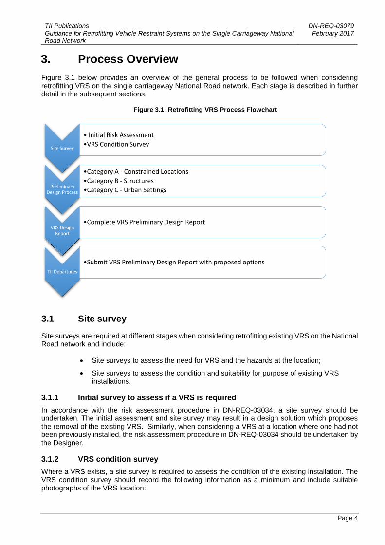
Figure 3.1 below provides an overview of the general process to be followed when considering retrofitting VRS on the single carriageway National Road network. Each stage is described in further detail in the subsequent sections.
Figure 3.1: Retrofitting VRS Process Flowchart
3.1 Site survey
Site surveys are required at different stages when considering retrofitting existing VRS on the National Road network and include:
Site surveys to assess the need for VRS and the hazards at the location;
Site surveys to assess the condition and suitability for purpose of existing VRS installations.
3.1.1 Initial survey to assess if a VRS is required
In accordance with the risk assessment procedure in DN-REQ-03034, a site survey should be undertaken. The initial assessment and site survey may result in a design solution which proposes the removal of the existing VRS. Similarly, when considering a VRS at a location where one had not been previously installed, the risk assessment procedure in DN-REQ-03034 should be undertaken by the Designer.
3.1.2 VRS condition survey
Where a VRS exists, a site survey is required to assess the condition of the existing installation. The VRS condition survey should record the following information as a minimum and include suitable photographs of the VRS location:
Site Survey
• Initial Risk Assessment
•VRS Condition Survey
Preliminary Design Process
•Category A - Constrained Locations
•Category B - Structures
•Category C - Urban Settings
VRS Design Report
•Complete VRS Preliminary Design Report
TII Departures
•Submit VRS Preliminary Design Report with proposed options

TII Publications DN-REQ-03079 Guidance for Retrofitting Vehicle Restraint Systems on the Single Carriageway National Road Network
February 2017
Page 5
Hazards at the location (existing and new)
Length of VRS
Approach to and departure from the hazards
VRS type including IS EN 1317 compliance status if known (is it a CE marked system?)
Post type
Post stability
Post spacing
Terminal type, upstream and downstream (are they EN 1317 Part 7 compliant?)
Set back
Working width
Height of VRS
Damage evident to the existing VRS
Grade of bolts used compared with manufacturer’s specification (if available)
Bolt attachments
Taper rate, if any
Connections to other barriers, if any
Parapet type – masonry, reinforced concrete, steel or aluminium.
VRS connection to parapet, if any.
Possible vehicle intrusion.
General condition of VRS (poor, fair, good)
This information should be used initially to decide if a replacement VRS is required.
A sample VRS condition survey template is provided in Appendix A and is available for download from the TII publications website http://tiipublications.ie/downloads/. The completed VRS condition survey template should be submitted where relevant as part of the VRS Preliminary Design Report submission to TII. Where multiple VRS on a route are being considered, the information gathered should be tabulated and analysed in order to prioritise repair and replacement programmes.
3.2 Overview of the preliminary design process
The design processes outlined for each category of constraint in the subsequent sections of this ITA document provide the Designer with a defined process to inform their design decisions and provide for a consultation and approval procedure with TII (See Figures 4.5, 5.6 & 6.3).They have not been developed to provide the Designer with a specific design solution for a particular constraint. The number of site specific constraints which could exist at any one hazard location on the National Road network means it is not practical to prescribe definitive solutions.

TII Publications DN-REQ-03079 Guidance for Retrofitting Vehicle Restraint Systems on the Single Carriageway National Road Network
February 2017
Page 6
3.2.1 General design principles
The general principles applied to the design processes can be summarised as follows:
Consult with TII to check if any improvement or refurbishment works are planned at the location into which VRS works can be incorporated.
Carry out an initial risk assessment to check if a VRS is actually required by identifying and categorising the hazard in accordance with DN-REQ-03034.
Assess if mitigation measures can be implemented to remove the need for a VRS.
Analyse the site specific constraints that may prohibit a compliant VRS design.
Develop suitable design options identifying the advantages and disadvantages of each.
Identify the preferred option with appropriate reasoning, including consideration of whole life cycle costs, and
Submit proposed design options including the preferred solution, including any necessary departures where relevant, within a VRS PDR to TII for approval.
Sample VRS PDR summary templates for each category of constraint are contained in Appendix B.
In some situations, a compliant design to DN-REQ-03034 may be achievable following assessment of the site specific constraints.
3.2.2 Development of preferred design options
A suite of possible design options are presented at the end of each section for each category of constraint within this document to assist the Designer in developing a final preferred solution. There are three tables for each constraint type presenting possible solutions which are broken down as follows:
Possible hazard mitigation measures.
Possible VRS design options.
Other possible options where mitigation measures or VRS solutions are not possible to implement.
The tables contained at the end of each section describe the advantages and disadvantages of the various options and provide details of limitations and requirements for incorporating the options into a preferred design solution. A solution may be a combination of the listed options or Designers may need to develop other innovative solutions beyond those listed in the tables, depending on the site specific characteristics. A final solution for a particular scenario will be dependent upon items such as the site specific constraints, the results of the design process and approval from TII as appropriate.
Worked examples for various scenarios are also included in Appendix C to further assist the Designer in developing a final preferred solution.
3.2.3 Whole life cycle cost analysis
As part of the design process the Designer shall consider the whole life cycle costs of the design solutions considered, including alternative mitigation measures to remove the need for a VRS.
While the initial cost of mitigation measures may be higher than the installation of a VRS e.g. purchasing additional land to allow removal of the hazard from the clear zone, the whole life costing of a VRS solution should be taken into account when considering the cost benefit analysis. To assist with this process, consideration may be given to the use of the SAVeRS tool. Using input parameters

TII Publications DN-REQ-03079 Guidance for Retrofitting Vehicle Restraint Systems on the Single Carriageway National Road Network
February 2017
Page 7
such as the road characteristics and collision data already embedded in the tool based on the region chosen, the SAVeRS tool can provide an estimate of the whole life costing of a VRS including construction, maintenance and repair costs of the system, plus potential injury costs based on the predicted crash rate calculated. The SAVeRS tool, guideline document and user manual can be downloaded at the link below.
http://www.saversproject.com/en/index.php
The Designer shall provide information in relation to the cost benefit analysis of the proposed design options when submitting a VRS PDR to TII for approval. Appendix E contains sample input data for use with the SAVeRS tool which has been incorporated into Worked Example 4 in Appendix C.
3.3 VRS Preliminary Design Report
The design procedures for retrofitting VRS on the National Road network presented in this document require the preparation of a VRS Preliminary Design Report (PDR) for submission to TII. If the VRS being considered are part of a minor improvement scheme being designed in accordance with DN-GEO-03030, the VRS PDR can be included as a section of the overall scheme PDR.
The purpose of the VRS PDR is to summarise the design process followed to arrive at the preferred solution in line with the procedures outlined in this document. The report shall:
Identify the physical constraints, issues and site specific challenges encountered at the VRS location being considered
Present the potential design solutions which the Designer has considered in order to account for the existing hazards, including any Relaxations and Departures from Standards required and
Outline the methodology adopted to arrive at these design solutions in line with the processes presented in this document.
VRS PDR templates for each category of constraint are contained in Appendix B and are available for download from the TII publications website http://tiipublications.ie/downloads/.
The VRS PDR shall be submitted through the TII departures website as follows:
https://web.nra.ie/departures/Home/Login/?ReturnUrl=%2fdepartures
Where an existing VRS is being replaced, the Designer shall complete the VRS condition survey template contained in Appendix A and submit it to TII as part of the VRS PDR submission. Worked examples of PDRs have been included in Appendix C for guidance.

TII Publications DN-REQ-03079 Guidance for Retrofitting Vehicle Restraint Systems on the Single Carriageway National Road Network
February 2017
Page 8
4. Category A - Constrained locations
Category A includes VRS at constrained locations where site conditions do not allow a compliant design. This section outlines the potential constraints that could be encountered. The design process to be followed when considering retrofitting a legacy VRS is described. Information in relation to potential solutions that may be applied in typical scenarios is also provided.
4.1 Potential site specific constraints
A broad range of constraints which do not allow for a compliant design to DN-REQ-03034 fall within this category. A non-exhaustive list is provided below.
Lack of working width or set-back for a new VRS (see Figure 4.1).
Installations within the working width or in front of the VRS (see Figure 4.2).
Accesses and junctions preventing the full length of need of the system being achieved (see Figure 4.3).
VRS at junctions (see Figure 4.4).
Land restrictions preventing a compliant design to DN-REQ-03034.
VRS not installed as per the Initial Type Testing.
Figure 4.1: Lack of set back or working width

TII Publications DN-REQ-03079 Guidance for Retrofitting Vehicle Restraint Systems on the Single Carriageway National Road Network
February 2017
Page 9
Figure 4.2: Installations within the clear zone
Figure 4.3: Accesses and junctions preventing full length of need
Figure 4.4: VRS continuing down a side road

TII Publications DN-REQ-03079 Guidance for Retrofitting Vehicle Restraint Systems on the Single Carriageway National Road Network
February 2017
Page 10
4.2 Design process and flow chart
The design process to be followed when considering retrofitting VRS at locations on the National Road network where site specific constraints do not allow a compliant design is presented in flowchart format in Figure 4.5. The following sections provide a breakdown of the steps involved to assist the Designer in developing the most appropriate design solution based on the site specific constraints.
Step 1: Consultation
The Designer shall consult with TII Network Management and/or the TII Road Safety Section to determine if there are any minor improvement, road safety or maintenance schemes planned for the location. This may allow integration of VRS repair or replacement works with other scheduled works.
Step 2: Hazard identification and risk assessment
The Designer shall visit the site to undertake a survey of the existing VRS and surrounding conditions to identify hazards that are currently being protected and any additional hazards that will require protection by the new VRS.
The Designer shall then undertake a risk assessment in accordance with DN-REQ-03034, including desk top studies to calculate sinuosity and collision rates. This process can be used to determine:
Whether or not a VRS is required at the location based on current data, and
It can inform design if a VRS is deemed necessary.
The Designer shall submit the completed DN-REQ-03034 Risk Assessment to TII as part of the VRS PDR. Where the results of the risk assessment show that a VRS is not required at the location, the Risk Assessment sheet will form the main part of the PDR. If the risk assessment findings indicate that a VRS is still required, the Designer shall proceed to the next step.
Step 3: Mitigation measures
The Designer shall determine whether mitigation measures can be implemented to sufficiently reduce or remove the hazard in order to remove the need for a VRS at the location. VRS are also regarded as a hazard and have associated maintenance costs. A mitigation measure that removes the need for a VRS is always preferable.
DN-REQ-03034 provides information in relation to hazard mitigation listing the various solutions in order of preference; VRS installation is listed as the least preferable option.
Step 4: Design compliance
Where it has been determined that a VRS is required, the Designer shall assess whether a DN-REQ-03034 compliant design can be implemented. If a compliant design cannot be implemented the Designer shall identify the constraints preventing a compliant design.
Step 5: Constraints identification
The Designer shall assess what specific constraint or combinations of constraints are present on site and analyse them so as to determine whether a bespoke design solution can be provided which will reduce the collision and injury risk for an errant road user. The options should be considered in line with the requirements outlined in the sample VRS PDR template contained in Appendix B.

TII Publications DN-REQ-03079 Guidance for Retrofitting Vehicle Restraint Systems on the Single Carriageway National Road Network
February 2017
Page 11
Step 6: VRS Preliminary Design Report
The VRS PDR provides a summary of the Designer’s assessment of the VRS location and details of the proposed design options developed. The Designer’s preferred solution with reasoning, including details of the whole life cycle cost analysis shall also be included.
The VRS PDR shall be submitted through the TII departures website:
https://web.nra.ie/departures/Home/Login/?ReturnUrl=%2fdepartures
Worked examples of VRS PDRs for VRS at constrained locations are included in Appendix C for guidance.
Preferred solution
The preferred design solution will be subject to approval by TII.

TII Publications DN-REQ-03079 Guidance for Retrofitting Vehicle Restraint Systems on the Single Carriageway National Road Network February 2017
Page 12
Figure 4.5: VRS preliminary design process flowchart: Constrained locations

TII Publications DN-REQ-03079 Guidance for Retrofitting Vehicle Restraint Systems on the Single Carriageway National Road Network
February 2017
Page 13
4.3 Development of preferred design solutions
The preferred design solution will be dependent on the various factors outlined in the previous section. The information in this section is provided to assist the Designer in developing the most appropriate solution for the site specific circumstances.
Tables 4.1 to 4.3 on the following pages provide a list of possible design options for VRS at constrained locations. The Designer may develop and propose solutions other than those included in the tables.
All solutions require approval from TII as per the design process outlined in this chapter.

TII Publications DN-REQ-03079 Guidance for Retrofitting Vehicle Restraint Systems on the Single Carriageway National Road Network February 2017
Page 14
Table 4.1: Possible design solutions for constrained locations – Mitigation measures
Solution Advantages Disadvantages Limitations on/Requirements for
use Revise the road layout or cross-section to lower the risk, e.g. increase the width
of the verge or improve the road alignment.
May reduce the overall risk ranking of the location and remove the
requirement for a VRS.
May facilitate removal of the hazard to create a forgiving roadside without the need for a VRS.
Additional lands will most likely need to be purchased to facilitate
this solution.
High initial costs to purchase land and to design and construct
solution.
Life cycle costs of a VRS solution (including installation, maintenance,
repair, accident and injury costs) should be considered versus the
purchase of additional land.
Regrade side slopes so as they are not considered a hazard to an errant vehicle
in line with DN-REQ-03034.
The need for a VRS may be mitigated creating a forgiving
roadside.
May require the purchase of additional land to accommodate
gentler slopes.
Knock on effects to existing drainage etc. would need to be
accounted for.
Land available may be limited. Life cycle cost analysis should be
considered.
Remove the hazard from the clear zone e.g. relocation of a utility pole outside
the clear zone or burying of a service to remove the need for the utility pole.
The need for a VRS may be mitigated creating a forgiving
roadside.
May not be feasible e.g. natural watercourse or steeply sloping
terrain adjacent to the road may be the hazard.
Third party consultations may be required e.g. removing a utility pole or
burying services.
Install passively safe road furniture. The need for VRS may be mitigated creating a forgiving roadside.
May be expensive to remove existing and replace with
passively safe in the retrofit scenario.
A life cycle cost analysis (including installation, maintenance, repair, and accident and injury costs) should be
considered versus using non-passively safe furniture with a VRS.
Clearance of vegetation/trees within the clear zone.
Need for VRS may be mitigated creating a forgiving roadside.
The rate of growth of vegetation may require regular maintenance which could increase the annual
cost.
Life cycle costs (including installation, maintenance, repair, accident and injury costs) should be considered
versus the cost of removing the vegetation.
Ecological/environmental impacts
should be considered.

TII Publications DN-REQ-03079 Guidance for Retrofitting Vehicle Restraint Systems on the Single Carriageway National Road Network February 2017
Page 15
Table 4.2: Possible design solutions for constrained locations - VRS Solutions
Solution Advantages Disadvantages Limitations on/Requirements for
use Higher containment VRS. A higher containment level may allow
installation of the VRS in locations where a lack of space is the
constraint.
Increased impact severity of collision Potentially higher installation costs.
A life cycle costs analysis should be considered as part of proposal.
Mandatory limitations on impact
severity levels should be considered.
Bespoke VRS solution. VRS can be designed to provide appropriate protection.
Aesthetic requirements can be
accounted for in design.
May be an expensive solution. Require approval for use by TII.
A life cycle costs analysis should be provided as part of proposal.
Crash cushions (end to end crash cushion/terminal).
Could be used to protect isolated hazards such as trees or utility poles instead of VRS which would require
approach and departure lengths.
May be aesthetic issues depending on the location.
Initial cost of installation may be high.
Crash cushions are still a hazard.
May not restrain a vehicle.
A life cycle costs analysis should be provided as part of proposal.
Use of innovative products that may be available on the market to
suit certain conditions.
May be designed to suit site specific circumstances.
May not be CE marked. Require approval for use by TII.
A life cycle costs analysis should be provided as part of proposal.

TII Publications DN-REQ-03079 Guidance for Retrofitting Vehicle Restraint Systems on the Single Carriageway National Road Network February 2017
Page 16
Table 4.3: Possible design solutions for constrained locations - Other Solution where mitigation/VRS not possible
Solution Advantages Disadvantages Limitations on/Requirements for use Delineation marker posts, preventative
road markings and signage. Alert the road user to the hazard. The hazard is highlighted to the
road user but is not protected. Only permitted where all other solutions have been shown to be unachievable
within the VRS PDR.
Solution hould be used in conjunction with other solutions e.g. high containment kerbs in conjunction with delineation
markers and appropriate preventative signage and road markings.
Approval for use should be obtained from
TII.
Not suitable for high speed locations.
Life cycle costs analysis should be provided as part of proposal.
High containment kerbs. May be suitable for use in lower speed locations in place of a
VRS.
Less visually intrusive.
Lower containment level, not suitable for use in high speed
locations.
Only permitted where all other solutions have been shown to be unachievable
within the VRS Preliminary Design Report.
Solution should be used in conjunction
with other solutions e.g. high containment kerbs in conjunction with delineation
markers and appropriate preventative signage and road markings.
Approval for use should be obtained from
TII.
Not suitable for high speed locations.
Life cycle costs analysis should be provided as part of proposal.

TII Publications DN-REQ-03079 Guidance for Retrofitting Vehicle Restraint Systems on the Single Carriageway National Road Network
February 2017
Page 17
5. Category B - Structures
Category B includes VRS at road bridges, rail bridges and culvert crossings. This section outlines the potential constraints that could be encountered at these locations. The design process to be followed when considering retrofitting a VRS is then described and information in relation to potential solutions that may be applied in typical scenarios is provided.
A major risk of pocketing may exist where VRS are connected to bridge parapets. The potential for pocketing occurs due to a sudden change in stiffness between the terminal and connecting VRS resulting in the rigid parapet end penetrating the vehicle.
VRS constraints at structures, relate to historical bridge parapets and the transition from the adjacent VRS to the bridge parapet itself. Other site specific constraints in relation to VRS design that fall into Category A may also be present at structures. The design process described in this section however is specific to VRS at structures. The Designer may need to combine some of the design processes from Category A and Category B to deal with all constraints at a particular location.
5.1 Potential constraints at structures
Figure 7 below shows an example of a river bridge crossing on the National Road network with constraints common to many similar crossings.
Figure 5.1: VRS at river bridge crossing
Typical VRS design challenges include:
Historical parapets with unknown containment values;
No direct connection or transition between the adjacent VRS and the bridge parapet, (see Figure 5.1); and
Adjacent VRS is a pre IS EN 1317 system with concrete posts (see Figure 5.2).

TII Publications DN-REQ-03079 Guidance for Retrofitting Vehicle Restraint Systems on the Single Carriageway National Road Network
February 2017
Page 18
Figure 5.2: No connection to bridge parapet
Figure 5.3 below represents a railway bridge crossing typical of those found on the National Road network. Issues associated with such locations include:
Pre IS EN 1317 parapet which may need to be replaced;
No transition included from the VRS to the bridge parapet;
An unapproved connection detail which does not appear to transition suitably from the semi-rigid barrier to the rigid concrete parapet 6 (further example shown in Figure 5.4); and
Adjacent VRS is a pre IS EN 1317 system with timber posts.
Figure 5.3: VRS at railway bridge crossing

TII Publications DN-REQ-03079 Guidance for Retrofitting Vehicle Restraint Systems on the Single Carriageway National Road Network
February 2017
Page 19
Figure 5.4: Unapproved connection detail
Figure 5.5 provides an example of a culvert crossing on the National Road network. The constraints from the photograph which are common to many similar culvert crossings are:
No end terminals provided;
VRS has no working width;
The length of need of the hazard is not catered for;
The VRS height above the carriageway is too low; and
The VRS is a pre IS EN 1317 system with timber posts.
Figure 5.5: VRS at culvert crossing
Further site constraints that could impact upon a compliant design to standards that may be encountered at structures include:

TII Publications DN-REQ-03079 Guidance for Retrofitting Vehicle Restraint Systems on the Single Carriageway National Road Network
February 2017
Page 20
Masonry parapets not designed to DN-STR-03011 – The Design of Vehicle and Pedestrian Parapets;
Cultural heritage issues may prohibit modification or demolition of an existing parapet;
Insufficient lands available to provide the required approach and departure lengths; and
Accesses or junctions located adjacent to the structure that may not allow the required approach and departure lengths.
5.2 Design process and flow chart
The design process to be followed when considering retrofitting VRS at structures on the National Road network is presented in flowchart format in Figure 5.6. Its aim is to assist the Designer in developing the most appropriate design solution so as to overcome the constraints outlined above and any other site specific issues that may exist. The following sections provide a breakdown of the steps involved.
Step 1: Consultation
Following identification of a VRS which requires replacement or repair the Designer shall contact the TII Bridge Management Section to determine if the structure is included in a capital refurbishment programme. This may allow integration of VRS repair or replacement works with other planned bridge refurbishment works.
Step 2: Hazard identification
The Designer shall visit the site to undertake a survey of the existing VRS and surrounding conditions to identify the hazards that are currently being protected and any additional hazards that may require protection by a new VRS.
Step 3: Mitigation measures
The Designer shall assess whether the hazard can be mitigated so as to remove the requirement for a VRS.
If deemed possible, mitigation measures should be implemented to remove the need for a VRS creating a forgiving roadside. The Designer shall assess the whole life cycle costs of installing a VRS versus the upfront costs of significant mitigation measures so as to ensure the most beneficial long term solution for the location is achieved. A summary of this process shall be submitted to TII in the VRS PDR.
At sites where it is not possible to mitigate the hazard, the Designer shall move to the next stage in the process.
Step 4: Design compliance
The Designer should check whether a VRS can be designed in accordance with DN-STR-03011 and/or DN-REQ-03034. If a compliant design cannot be implemented the Designer should identify the constraints preventing the design.

TII Publications DN-REQ-03079 Guidance for Retrofitting Vehicle Restraint Systems on the Single Carriageway National Road Network
February 2017
Page 21
Step 5: Constraint identification
The Designer should identify any constraints that could prevent a compliant design and installation of a VRS to DN-STR-03011 and/or DN-REQ-03034. Common constraints at river bridges, rail bridges and culvert crossings have been outlined earlier in this Section.
The Designer should assess what specific constraint or combinations of different constraints are present on site and analyse them so as to determine whether a bespoke design solution can be provided which will reduce the injury and collision risk for an errant road user. The options should be considered in line with the requirements outlined in the sample VRS PDR contained in Appendix B.
Step 6: Design options
The Designer should develop appropriate design options to overcome the site specific constraints in consultation with the TII Bridge Management Section. The options should be considered in line with the requirements outlined in the sample VRS PDR contained in Appendix B.
A possible solution to protect an existing concrete parapet may be to run a VRS with adequate set-back and working width across the structure in front of the vehicle parapet as there may be space available in the hard shoulder to do so. However if there is only a narrow hard strip, a compliant VRS design may not be achievable in front of the bridge parapet. In cases like this a higher containment VRS with a reduced working width could be installed.
Step 7: VRS Preliminary Design Report
The VRS PDR provides a summary of the Designer’s assessment of the VRS location with details of the design options developed and the Designer’s preferred solution, as agreed with the TII Bridge Management Section, including details of the whole life cycle cost analysis.
All connections from a VRS to a bridge parapet shall require a suitable transition. Where the preferred solution includes an untested transition detail, this shall be submitted to TII at detailed design stage for assessment under the TII Transition Assessment Procedure, following approval of the preliminary design solution by TII.
The VRS PDR shall be submitted through the TII departures website:
https://web.nra.ie/departures/Home/Login/?ReturnUrl=%2fdepartures
Worked examples of VRS PDR for VRS at Structures are included in Appendix C for guidance.
Preferred solution
The preferred design solution will be subject to approval by the TII Bridge Management Section.

TII Publications DN-REQ-03079 Guidance for Retrofitting Vehicle Restraint Systems on the Single Carriageway National Road Network February 2017
Page 22
Figure 5.6: VRS preliminary design process flowchart – Structures

TII Publications DN-REQ-03079 Guidance for Retrofitting Vehicle Restraint Systems on the Single Carriageway National Road Network
February 2017
Page 23
5.3 Development of preferred design solutions
The preferred design solution will be dependent on various factors including:
The hazard being protected;
The type of structure
The site specific constraints;
Land available;
Other planned works;
Heritage issues; and
The existing parapets and VRS.
Tables 5.1 to 5.3 list possible design options for VRS at structures which are provided to assist the Designer in developing the most appropriate solution for the site specific characteristics. All solutions require consultation with, and approval from, TII as per the process outlined earlier.

TII Publications DN-REQ-03079 Guidance for Retrofitting Vehicle Restraint Systems on the Single Carriageway National Road Network February 2017
Page 24
Table 5.1: Possible design solutions for VRS at structures – Mitigation Measures
Solution Advantages Disadvantages Limitations on/Requirements for use Taper bridge parapets away
from the carriageway. Hazard of parapet ends
reduced.
The need for VRS may be mitigated thus creating a
forgiving roadside.
The tapered parapets are still a hazard and it may not be possible to taper
outside the clear zone.
May be an expensive solution for a retrofit scenario.
May require the purchase of additional
land to facilitate construction.
Should not be used if it is possible to install a suitable VRS on the approach and departure to the bridge and connect to the parapet using a
suitable transition.
Length of need should be accommodated on the approach and departure.
Land available may be limited.
Heritage structures may restrict works.
Life cycle costs analysis should be provided as
part of the proposal.
Increase the length of a culvert so that the parapets are outside the clear zone.
The need for a VRS may be mitigated thus creating a
forgiving roadside
May be an expensive solution for retrofit scenario.
May require the purchase of additional
land to facilitate construction.
Land available may be limited.
Heritage structures may restrict works.
May require a Section 50 application.
Life cycle costs analysis should be provided as part of the proposal.
Remove the culvert headwalls and create a passively safe
end to a pipe culvert.
The need for a VRS may be mitigated thus creating a
forgiving roadside.
The solution may leave an unprotected edge which would be a hazard for
pedestrians.
Not suitable for larger culverts.
Should not be used where deep water present.
Should not be used where pedestrian activity is likely.

TII Publications DN-REQ-03079 Guidance for Retrofitting Vehicle Restraint Systems on the Single Carriageway National Road Network February 2017
Page 25
Table 5.2: Possible design solutions for VRS at structures - VRS Solutions
Solution Advantages Disadvantages Limitations on/Requirements for use Install VRS in front of the existing bridge parapet,
suitable solution for locations where sufficient width exists
across the bridge deck.
Parapet works not required.
VRS protects driver from hazard of parapet and parapet ends.
The need for a connection between
the parapet and a VRS on the approach to and the departure from
the structure removed.
Maintenance of VRS required.
May take from aesthetics of bridge.
Working width and setback of VRS
must be maintained across the structure.
Additional works may be required to anchor the VRS posts if bridge deck
unsuitable e.g. old masonry arch bridges.
Pedestrian activity may be affected.
VRS will be closer to the road than the
exiting parapet.
Working width and setback of VRS should be accommodated.
It may not be possible to suitably install
VRS posts in the bridge deck.
May not be suitable for a location of natural beauty.
May not be suitable for a heritage
structure.
Cyclists and pedestrians need to be accommodated where appropriate.
Existing uses e.g. parking in hard
shoulder for access to recreation area need to be considered.
A life cycle costs analysis should be
provided as part of proposal.
Modify masonry parapets to include RC core with masonry
cladding to enable VRS connection to approach and
departure. May be incorporated either end of the parapets for longer bridges where the existing parapet
provides sufficient containment.
Parapet ends are protected.
Suitable connection and transition can be designed.
Full length of need can be facilitated.
A RC core with masonry cladding solution can sustain aesthetics.
Initial cost of installation may be high.
Expensive bridge upgrade works may be required.
All proposed untested transitions/connections require
submission to TII for approval through the departures website.
For shorter span bridges, full parapet
reconstruction may be required across the full bridge span.
Heritage structures.
A life cycle costs analysis should be
provided as part of the proposal.

TII Publications DN-REQ-03079 Guidance for Retrofitting Vehicle Restraint Systems on the Single Carriageway National Road Network February 2017
Page 26
Solution Advantages Disadvantages Limitations on/Requirements for use Full parapet replacement to include full length of need on
approach and departure.
Parapet ends are protected.
Full length of need on approach and departure can be provided.
Suitable transition can be provided.
May be suitable for urban locations
where full length of need may not be required due to lower speeds.
May be an expensive solution for a retrofit scenario.
Expensive bridge upgrade works may be required to connect reconstructed
parapet.
Requires TII approval.
Heritage Structures.
A life cycle costs analysis should be provided as part of the proposal.
Bespoke VRS solution. Parapet can be designed to provide appropriate protection.
Aesthetic requirements can be
accounted for in design.
May be an expensive solution. Requires TII approval.
A life cycle costs analysis should be provided as part of proposal.
Install crash cushions at exposed parapet ends.
Protects the parapet ends.
Expensive bridge upgrade works may be avoided.
Length of need may not be accommodated on approach and
departure.
Only protects against collision risk at parapet ends.
Will not improve the performance of
the existing parapet.
May take from aesthetics of bridge.
May prove an expensive solution.
Length of need should be accommodated on approach and departure.
Heritage structures.
Requires TII approval.
A life cycle costs analysis should be
provided as part of the proposal.
Higher containment VRS. Working width for smaller vehicles will be reduced and may allow
installation in front of an existing parapet where space constraints
exist.
Increased impact severity of collision with higher containment VRS.
Potentially higher installation costs May take from aesthetics of bridge.
Bridge structure may not be capable of accommodating additional loading of
higher containment parapet.
Life cycle costs analysis should be provided as part of the proposal.

TII Publications DN-REQ-03079 Guidance for Retrofitting Vehicle Restraint Systems on the Single Carriageway National Road Network February 2017
Page 27
Solution Advantages Disadvantages Limitations on/Requirements for use May allow installation on approach
and departure where space constraints exist (a suitable
connection/transition to the parapet would still be required).
Table 5.3: Possible design solutions for VRS at structures - Other Solutions where mitigation/VRS not possible
Solution Advantages Disadvantages Limitations on/Requirements for use Delineation Markers,
preventative signage and road markings.
Alerts the road user to the hazard. The hazard is highlighted to the road user but is not protected.
Only permitted where all other solutions have been shown to be unachievable
within the VRS PDR.
Should only be used in conjunction with other solutions e.g. high containment kerbs in conjunction with delineation
markers and appropriate preventative signage and road markings.

TII Publications DN-REQ-03079 Guidance for Retrofitting Vehicle Restraint Systems on the Single Carriageway National Road Network
February 2017
Page 28
6. Category C - Urban settings
Category C includes VRS in urban settings or speed limit zones where the speed limit may have been reduced subsequent to the installation of the VRS. The design process outlined in this section is mainly to provide a risk based decision making process for use when considering the removal of legacy VRS at such locations, while highlighting the potential constraints that could be encountered. Information in relation to potential solutions that may be applied in typical scenarios is also provided.
6.1 Potential issues in urban settings or speed limit zones
The main issues that may be encountered in urban settings are related to the actual need for a VRS. The Designer shall assess the hazard that is being protected by the VRS and determine whether the hazard remains following the introduction of the reduced speed limit and traffic calming measures. Figures 6.1 and 6.2 show locations where a VRS was installed when the speed limit was 100 km/h but has subsequently been reduced.
Figure 6.1: VRS within urban settings
Figure 6.2: VRS within speed limit zones

TII Publications DN-REQ-03079 Guidance for Retrofitting Vehicle Restraint Systems on the Single Carriageway National Road Network
February 2017
Page 29
6.2 Design process and flow chart
The design process to be followed when considering retrofitting VRS located in urban settings or speed limit zones is presented in flowchart format in Figure 6.3. The following sections provide a breakdown of the steps involved.
Step 1: Consultation
The Designer shall consult with TII Network Management and/or TII Road Safety Section to determine if there are any minor improvement, road safety or maintenance schemes planned for the location. This may allow integration of VRS repair/replacement or removal works with other scheduled works.
Step 2: Hazard identification
The Designer shall visit the site to undertake a survey of the existing VRS and surrounding conditions to identify the hazards that are currently being protected and any additional hazards that may require protection by a new VRS.
Step 3: Traffic calming measures
The Designer should note whether traffic calming measures are in place at the VRS location. Traffic calming measures could include, but are not limited to:
Speed limit reduced to 50 or 60 km/h;
Segregated turning lanes;
Reduced carriageway width;
Gateway set up;
Hatched central reserve.
If traffic calming measures have been introduced such as a reduced speed limit, the Designer
should assess on site if vehicle speeds have actually been reduced sufficiently to justify VRS
removal.
Step 4: Third party considerations
The Designer should assess whether there are any third party considerations that could require the installation of a VRS. The priority of the VRS in these circumstances may be to protect the third party consideration from an errant vehicle as opposed to protecting the road user from a roadside hazard. Third party considerations could include, but are not limited to:
Playgrounds;
Playing pitches;
Schools;
Monuments;
ESB sub stations;
Pedestrians under a bridge.
If the risk assessment finds that the hazard no longer remains as a result of traffic calming measures and there are no third party considerations that could require a VRS, the Designer should consider removing the VRS. The Designer shall submit a record of their completed risk assessment (steps 2 – 4) with appropriate reasoning for removal of the VRS to TII.
TII Publications DN-REQ-03079 Guidance for Retrofitting Vehicle Restraint Systems on the Single Carriageway National Road Network
February 2017
Page 30
If the risk assessment finds that the hazard remains or there are third party considerations, the Designer shall proceed to the next step.
Step 4: Mitigation measures
The Designer should assess whether the hazard can be mitigated so as to remove the requirement for a VRS. Mitigation measures in urban settings or speed limit zones may include:
Relocating hazards outside of the reduced clear zone for urban areas;
Piping and backfilling of drainage ditches.
If deemed possible, mitigation measures should be implemented to remove the need for a VRS creating a forgiving roadside. The Designer should assess the costs of mitigation measures versus the whole life cycle costs of a VRS solution. The VRS PDR submitted to TII for approval should indicate that the mitigation measure is the preferred option.
Where it is not possible to mitigate the hazard the Designer should move to the next stage in the process.
Step 5: Design compliance
When it has been determined that a VRS is required and the hazard cannot be mitigated, the Designer should assess whether a DN-REQ-03034 compliant design can be implemented. If a compliant design cannot be implemented the Designer should identify the constraints preventing the design.
Step 6: Constraints identification
The Designer should identify any constraints that could prevent a compliant design and installation of a VRS to DN-REQ-03034. Constraints include:
Domestic/commercial/agricultural accesses;
Street furniture;
Cultural heritage;
Headstones/monuments;
Town/village name installations;
Pedestrian/cyclist facilities.
The Designer should assess what specific constraint or combination of constraints are present on site and analyse them to determine whether a bespoke design solution can be provided which will minimise the collision risk for an errant road user. The options should be considered in line with the requirements outlined in the sample VRS PDR contained in Appendix B.
TII Publications DN-REQ-03079 Guidance for Retrofitting Vehicle Restraint Systems on the Single Carriageway National Road Network
February 2017
Page 31
Step 7: VRS Preliminary Design Report
The VRS PDR provides a summary of the Designer’s assessment of the VRS location with details of the design options developed and the Designer’s preferred solution with reasoning, including details of the whole life cycle cost analysis.
The VRS PDR shall be submitted through the TII departures website:
https://web.nra.ie/departures/Home/Login/?ReturnUrl=%2fdepartures
Worked examples of VRS PDR have been included in Appendix C for guidance.
Preferred solution
The preferred design solution will be subject to approval by TII.

TII Publications DN-REQ-03079 Guidance for Retrofitting Vehicle Restraint Systems on the Single Carriageway National Road Network February 2017
Page 32
Figure 6.3: VRS preliminary design process flowchart – Urban Settings

TII Publications DN-REQ-03079 Guidance for Retrofitting Vehicle Restraint Systems on the Single Carriageway National Road Network
February 2017
Page 33
6.3 Development of preferred design solutions
The preferred design solution will be dependent on various factors at a specific location including:
the hazard type at the location;
whether the VRS is still required or not post traffic calming measures;
whether or not there are third party considerations to be accounted for in the design; and
the presence of any of the various constraints listed in the previous section.
Tables 6.1 to 6.3 include information to assist the Designer in developing the most appropriate solution for the site specific circumstances.
All solutions require approval from TII as per the process outlined earlier in this section.

TII Publications DN-REQ-03079 Guidance for Retrofitting Vehicle Restraint Systems on the Single Carriageway National Road Network February 2017
Page 34
Table 6.1: Possible design solutions for VRS in urban settings – Mitigation Measures
Solution Advantages Disadvantages Limitations on/Requirements for use Removal of VRS. The VRS, being a hazard in itself, is
removed.
Reduced collision risk to road users.
Cost of removal. The roadside feature should no longer be considered a hazard following completion
of a risk assessment.
Approval for use shall be obtained from TII prior to removal.
Relocate hazards outside of reduced clear zone for
urban areas.
Hazards removed from the clear zone.
Reduced collision risk to road users.
May require the purchase of additional land, making it an expensive solution.
Approval for use shall be obtained from TII.
Pipe and backfill drainage ditches.
The hazard of a level difference is removed.
Reduced collision risk to road users.
Could lead to flooding if predicted flows not catered for.
Approval for use shall be obtained from TII.
A life cycle cost analysis of mitigation should be considered.
Table 6.2: Possible design solutions for VRS in urban settings – VRS Solutions
Solution Advantages Disadvantages Limitations on/Requirements for use Bespoke VRS solution. VRS can be designed to provide
appropriate protection.
Aesthetic requirements can be accounted for in design.
May be an expensive solution. Approval for use shall be obtained from TII.
A life cycle costs analysis should be provided as part of the proposal.
Crash Cushions (end to end crash cushion/terminal).
Could be used to protect isolated hazards such as trees or utility poles instead of a VRS which would require
approach and departure lengths.
May be aesthetic issues depending on the location.
Installation costs may be high.
Crash cushions are still a hazard.
A life cycle costs analysis should be provided as part of the proposal.
Higher Containment VRS. Working width for smaller vehicles may be reduced and may allow installation in front of an existing parapet where space
constraints exist.
Life cycle costs (including injury costs) may be reduced.
Increased impact severity of collision Potentially higher installation costs.
A life cycle costs analysis should be provided as part of the proposal.

TII Publications DN-REQ-03079 Guidance for Retrofitting Vehicle Restraint Systems on the Single Carriageway National Road Network February 2017
Page 35
Table 6.3: Possible design solutions for VRS in urban settings - Other Solutions where mitigation/VRS not possible
Solution Advantages Disadvantages Limitations on/Requirements for use Delineation Markers
(not a standalone solution, should be used in conjunction with other
solutions, see limitations).
Alerts the road user to the hazard. The hazard is highlighted to the road user but is not protected.
Only permitted where all other solutions have been shown to be unachievable with back up information within the VRS PDR.
Not suitable for high speed locations.
Approval for use should be obtained from
TII. Should be used in conjunction with other
solutions e.g. high containment kerbs with appropriate signage.
A life cycle costs analysis should be
provided as part of the proposal.
High Containment kerbs. May be suitable for use in lower speed urban locations in place of VRS.
Less visually intrusive.
Lower containment. Approval for use should be obtained from TII.
Not suitable for high speed locations.
Should be used in conjunction with other solutions e.g. high containment kerbs in conjunction with delineation markers and
appropriate preventative signage and road markings.

TII Publications DN-REQ-03079 Guidance for Retrofitting Vehicle Restraint Systems on the Single Carriageway National Road Network
February 2017
Page 36
VRS Condition Survey Template

TII Publications DN-REQ-03079 Guidance for Retrofitting Vehicle Restraint Systems on the Single Carriageway National Road Network
February 2017
Page 37
VRS Condition Survey
VRS ID/Description: Date: Inspected by:
Site Survey Notes
Hazards
Approach to and departure from hazards
VRS type (including EN 1317 compliance status if known)
Post type
Post stability
Post spacing
Terminal Upstream
Terminal Downstream
Set back
Working width
Height of VRS above pavement (<1.5m set back)
Height of VRS above ground (>1.5m set back)
Grade of bolts used compared with manufacturer’s specification
Bolt attachments
Taper rate, if any
Parapet type – masonry, reinforced concrete, steel or aluminium
VRS connection to parapet, if any
Possible vehicle intrusion
Damage Including Description
Observations:
Signed: _________________________________________

TII Publications DN-REQ-03079 Guidance for Retrofitting Vehicle Restraint Systems on the Single Carriageway National Road Network
February 2017
Page 38
VRS Condition Survey
Photos

TII Publications DN-REQ-03079 Guidance for Retrofitting Vehicle Restraint Systems on the Single Carriageway National Road Network
February 2017
Page 39
Sample VRS Preliminary Design Report Summary Template

TII Publications DN-REQ-03079 Guidance for Retrofitting Vehicle Restraint Systems on the Single Carriageway National Road Network February 2017
Page 40
Category A – VRS Preliminary Design Report Template
VRS ID / Location: VRS Preliminary Design Report Summary
VRS at Constrained Location
Description:
Details.
Length: xxxm
Insert Image Insert Image Insert Image
Consultation Outcome
TII Network Management
Identify the Hazard(s) Summary

TII Publications DN-REQ-03079 Guidance for Retrofitting Vehicle Restraint Systems on the Single Carriageway National Road Network February 2017
Page 41
Analysis
Need for VRS (reference DN-REQ-03034 - Risk Assessment): Is the VRS still required post risk assessment?
Can mitigation measures be implemented (Yes/No)? If “Yes” include proposals and projected life cycle costs
Can the VRS be designed in accordance with DN-REQ-03034 (Yes/No)? If “No” identify the constraints
Design Speed: Road Cross Section & Traffic Volumes:
Design Options Considered (Attach drawings as required)
Relaxations and Departures Observations
Option 1:

TII Publications DN-REQ-03079 Guidance for Retrofitting Vehicle Restraint Systems on the Single Carriageway National Road Network February 2017
Page 42
Design Options Considered (Attach drawings as required)
Relaxations and Departures Observations
Option 2:
Option 3:
Preferred Option Reasoning Whole Life Cycle Cost Analysis
Provide details of the Designers proposed solution Provide reasoning as to why this option was chosen
over others
Provide details of the life cycle cost analysis undertaken as part of the
preferred solution decision

TII Publications DN-REQ-03079 Guidance for Retrofitting Vehicle Restraint Systems on the Single Carriageway National Road Network February 2017
Page 43
Category B – VRS Preliminary Design Report Template
VRS ID / Location: VRS Preliminary Design Report Summary
VRS at Structures
Description:
Details.
Length: xxxm
Insert Image Insert Image Insert Image
Consultation Outcome
TII Bridge Management Section
Identify the Hazard(s) Summary

TII Publications DN-REQ-03079 Guidance for Retrofitting Vehicle Restraint Systems on the Single Carriageway National Road Network February 2017
Page 44
Analysis
Can mitigation measures be implemented (Yes/No)? If “Yes” include proposals and projected life cycle costs
Can the VRS be designed in accordance with DN-STR-03011 (Yes/No)? If “No” identify the constraints
Design Speed: Road Cross Section & Traffic Volumes:
Design Options Considered (Attach drawings as required)
Relaxations and Departures Observations
Option 1:
Option 2:

TII Publications DN-REQ-03079 Guidance for Retrofitting Vehicle Restraint Systems on the Single Carriageway National Road Network February 2017
Page 45
Design Options Considered (Attach drawings as required)
Relaxations and Departures Observations
Option 3:
Preferred Option Reasoning Whole Life Cycle Cost Analysis
Provide details of the Designers proposed solution Provide reasoning as to why this option was chosen
over others
Provide details of the life cycle cost analysis undertaken as part of the
preferred solution decision

TII Publications DN-REQ-03079 Guidance for Retrofitting Vehicle Restraint Systems on the Single Carriageway National Road Network February 2017
Page 46
Category C – VRS Preliminary Design Report Template
Barrier ID / Location: VRS Preliminary Design Report Summary
VRS in Urban Settings
Description:
Length:
Insert Image Insert Image Insert Image
Consultation Outcome
TII Network Management
Identify the Hazard(s) Summary
Traffic Calming Measures Description
Third Party Considerations Description

TII Publications DN-REQ-03079 Guidance for Retrofitting Vehicle Restraint Systems on the Single Carriageway National Road Network February 2017
Page 47
Analysis
Are traffic calming measures in place (Yes/No)? Have vehicle speeds been adequately reduced (Yes/No)?
Are there third party considerations (Yes/No)? Is the VRS still required (Yes/No)?
Can mitigation measures be implemented (Yes/No)? If “Yes” include proposals and projected life cycle costs
Can the VRS be designed in accordance with DN-REQ-03034 (Yes/No)? If “No” identify the constraints
Design Speed: Road Cross Section & Traffic Volumes:
Design Options Considered (Attach drawings as required)
Relaxations and Departures Observations
Option 1:

TII Publications DN-REQ-03079 Guidance for Retrofitting Vehicle Restraint Systems on the Single Carriageway National Road Network February 2017
Page 48
Option 2:
Option 3:
Preferred Option Reasoning Whole Life Cycle Cost Analysis
Provide details of the Designers proposed solution Provide reasoning as to why this option was chosen
over others
Provide details of the life cycle cost analysis undertaken as part of the preferred solution
decision

TII Publications DN-REQ-03079 Guidance for Retrofitting Vehicle Restraint Systems on the Single Carriageway National Road Network
February 2017
Page 49
VRS Preliminary Design Report Summary - Worked Examples

TII Publications DN-REQ-03079 Guidance for Retrofitting Vehicle Restraint Systems on the Single Carriageway National Road Network February 2017
Page 50
Worked Example 1 – Category A, VRS at a constrained location
VRS ID / Location: N56DL-01 (N56DL_100066_S1_B4) VRS Preliminary Design Report Summary
VRS at Constrained Location
Description: A short section of existing untensioned
corrugated VRS on timber posts with a ramped terminal upstream and full height fish tail
terminal downstream.
Length: 15m
Consultation Outcome
TII Network Management Following consultation with AN Other on 11/08/2016 it has been established that there are no minor
improvement, road safety or maintenance schemes planned for this location.
Identify the Hazard(s) Summary
Steep embankment slope and water of likely depth >0.6m
Steep slope into deep water to the west.
Substantial fixed object extending above the ground by >150mm
A low stone wall approximately 600m in length but with no piers.
Substantial fixed object extending above the ground by >150mm
There are 2 indented tourist laybys.
TII Publications DN-REQ-03079 Guidance for Retrofitting Vehicle Restraint Systems on the Single Carriageway National Road Network February 2017
Page 51
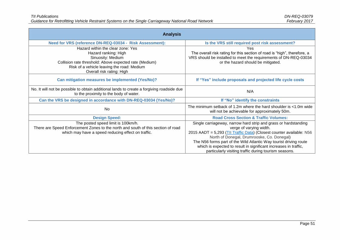
Analysis
Need for VRS (reference DN-REQ-03034 - Risk Assessment): Is the VRS still required post risk assessment?
Hazard within the clear zone: Yes Hazard ranking: High
Sinuosity: Medium Collision rate threshold: Above expected rate (Medium)
Risk of a vehicle leaving the road: Medium Overall risk rating: High
Yes The overall risk rating for this section of road is “high”, therefore, a
VRS should be installed to meet the requirements of DN-REQ-03034 or the hazard should be mitigated.
Can mitigation measures be implemented (Yes/No)? If “Yes” include proposals and projected life cycle costs
No. It will not be possible to obtain additional lands to create a forgiving roadside due to the proximity to the body of water.
N/A
Can the VRS be designed in accordance with DN-REQ-03034 (Yes/No)? If “No” identify the constraints
No The minimum setback of 1.2m where the hard shoulder is <1.0m wide
will not be achievable for approximately 50m.
Design Speed: Road Cross Section & Traffic Volumes:
The posted speed limit is 100km/h. There are Speed Enforcement Zones to the north and south of this section of road
which may have a speed reducing effect on traffic.
Single carriageway, narrow hard strip and grass or hardstanding verge of varying width.
2015 AADT = 5,293 (TII Traffic Data) (Closest counter available: N56 North of Donegal, Drumrooske, Co. Donegal)
The N56 forms part of the Wild Atlantic Way tourist driving route which is expected to result in significant increases in traffic,
particularly visiting traffic during tourism seasons.

TII Publications DN-REQ-03079 Guidance for Retrofitting Vehicle Restraint Systems on the Single Carriageway National Road Network February 2017
Page 52
Design Options Considered (Attach drawings as required)
Relaxations and Departures Observations
Option 1:
Install new modular P4/T110 end terminal tested to prEN 1317-7 with no connection to existing wall.
The slope hazard and trees are not fully protected at the upstream end.
The existing wall is within the Clear Zone and would
be left unprotected.
A P4/T110 end terminal tested to prEN 1317-7 will protect the end of wall hazard. The linear face of the wall should deflect errant vehicles back towards the road.
The layby indents are considered momentary.
This solution is sympathetic to the scenic location.
Option 2:
Install approximately 400m of additional VRS.
The minimum setback of 1.2m where the hard shoulder is <1.0m wide will not be achievable for
approximately 50m.
The hazard will not be protected where the VRS breaks at the laybys.
This would have a visual impact on the scenic nature of the location.
Breaks in the VRS would be required for two number layby recesses and one
access to the water, which will require additional terminals to be installed.
The presence of the VRS including the terminals will reduce visibility from the
laybys for exiting traffic. The minimum required setback will not be achievable as hard strip narrows to < 1.0m
in places. The space for pedestrians (particularly
where close to lay-bys) will be significantly reduced by the presence of a VRS.
Option 3:
N/A N/A N/A
TII Publications DN-REQ-03079 Guidance for Retrofitting Vehicle Restraint Systems on the Single Carriageway National Road Network February 2017
Page 53
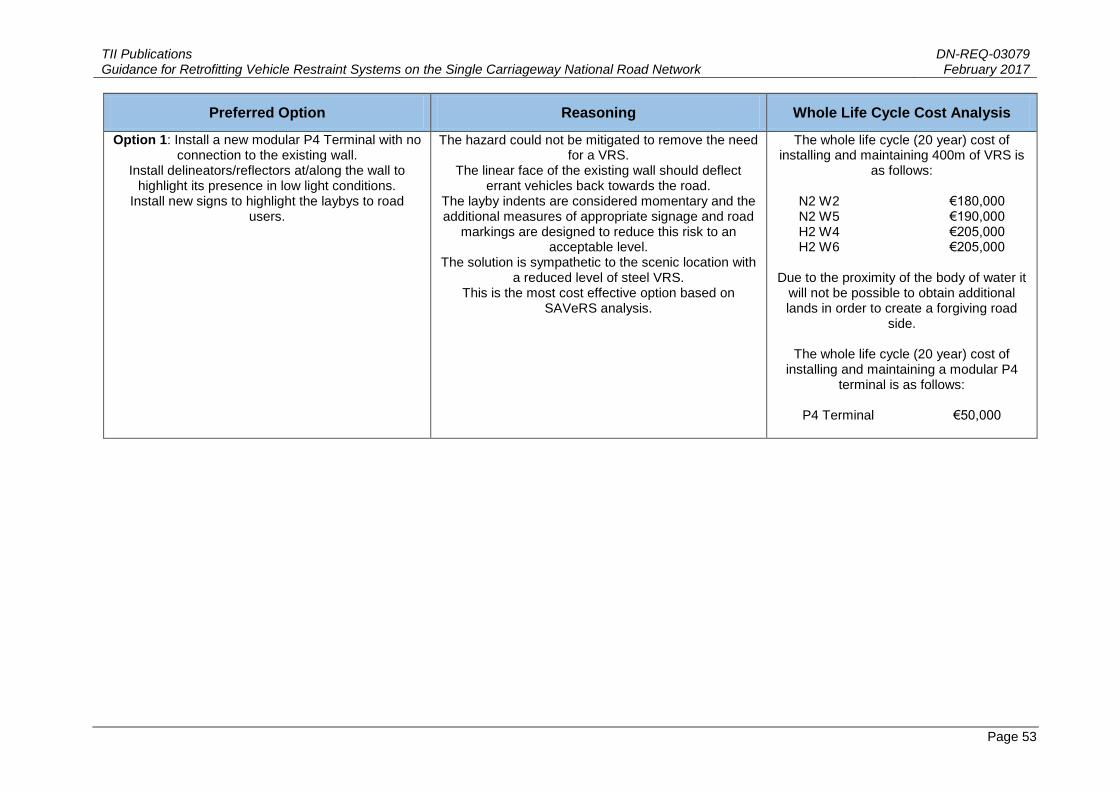
Preferred Option Reasoning Whole Life Cycle Cost Analysis
Option 1: Install a new modular P4 Terminal with no connection to the existing wall.
Install delineators/reflectors at/along the wall to highlight its presence in low light conditions.
Install new signs to highlight the laybys to road users.
The hazard could not be mitigated to remove the need for a VRS.
The linear face of the existing wall should deflect errant vehicles back towards the road.
The layby indents are considered momentary and the additional measures of appropriate signage and road
markings are designed to reduce this risk to an acceptable level.
The solution is sympathetic to the scenic location with a reduced level of steel VRS.
This is the most cost effective option based on SAVeRS analysis.
The whole life cycle (20 year) cost of installing and maintaining 400m of VRS is
as follows:
N2 W2 €180,000 N2 W5 €190,000 H2 W4 €205,000 H2 W6 €205,000
Due to the proximity of the body of water it
will not be possible to obtain additional lands in order to create a forgiving road
side.
The whole life cycle (20 year) cost of installing and maintaining a modular P4
terminal is as follows:
P4 Terminal €50,000
TII Publications DN-REQ-03079 Guidance for Retrofitting Vehicle Restraint Systems on the Single Carriageway National Road Network February 2017
Page 54
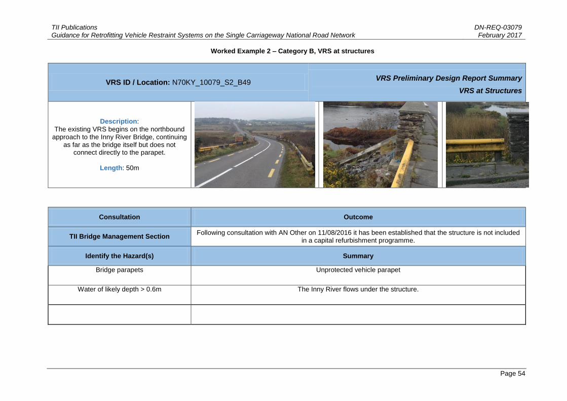
Worked Example 2 – Category B, VRS at structures
VRS ID / Location: N70KY_10079_S2_B49 VRS Preliminary Design Report Summary
VRS at Structures
Description: The existing VRS begins on the northbound
approach to the Inny River Bridge, continuing as far as the bridge itself but does not
connect directly to the parapet.
Length: 50m
Consultation Outcome
TII Bridge Management Section Following consultation with AN Other on 11/08/2016 it has been established that the structure is not included
in a capital refurbishment programme.
Identify the Hazard(s) Summary
Bridge parapets Unprotected vehicle parapet
Water of likely depth > 0.6m The Inny River flows under the structure.

TII Publications DN-REQ-03079 Guidance for Retrofitting Vehicle Restraint Systems on the Single Carriageway National Road Network February 2017
Page 55
Analysis
Can mitigation measures be implemented (Yes/No)? If “Yes” include proposals and projected life cycle costs
No. It will not be possible to obtain additional lands to protect and errant road user from the level difference to the adjacent land on the approach to the structure.
N/A
Can the VRS be designed in accordance with DN-STR-03011 (Yes/No)? If “No” identify the constraints
No Masonry parapet with unknown containment.
Pre IS EN 1317 parapet which may need to be replaced.
Design Speed: Road Cross Section & Traffic Volumes:
The posted speed limit is 100km/h.
Single carriageway with narrow hard strip and grass or hardstanding verge of varying width. 2015 AADT = 2,599 (TII Traffic Data) (Closest counter available: N70 Between Caherciveen and
Glenbeigh, Gortaforia, Co. Kerry)
Design Options Considered (Attach drawings as required)
Relaxations and Departures Observations
Option 1:
Replace the existing VRS on a like-for-like basis with an IS EN:1317 compliant design
A departure regarding the VRS length (<45m, excluding hazard length) will be required.
None
Option 2:
Following an initial consultation with the TII Bridge Management Section a full redesign of the existing
VRS to include an approved transition and connection to a reconstructed parapet may be
appropriate.
None envisaged if an approved transition and connection to the reconstructed parapet is detailed as
part of the redesign.
This option would include for the removal of the existing VRS. The upstream terminal would be upgraded to prEN 1317-7 T110 (P4) performance class. A 2m section of
the parapet would be demolished and replaced with a reinforced concrete
parapet. This would enable the upstream and downstream terminals of the VRS to
directly connect to the parapet.
Option 3:

TII Publications DN-REQ-03079 Guidance for Retrofitting Vehicle Restraint Systems on the Single Carriageway National Road Network February 2017
Page 56
Design Options Considered (Attach drawings as required)
Relaxations and Departures Observations
Install a crash cushion on the approach to the bridge parapet.
None envisaged Will address the collision risk of the parapet end but will not address the collision risk associated with the level difference to the
adjacent land.
Preferred Option Reasoning Whole Life Cycle Cost Analysis
Option 2: This option includes for the removal of the existing VRS. The upstream terminal will be
upgraded to P4 performance class. The downstream terminal will transition and connect to a newly
constructed reinforced concrete parapet. The design will require input and approval from the TII Bridge
Management Section.
Option 1 will not directly connect to the structure. This could result in pocketing and could increase the
severity of injury in the event of a collision.
Option 3 will not protect an errant road user from the level difference to the adjacent land on the approach
to the structure.
Whole life cycle (20 year) cost of installing and maintaining a VRS as well as
constructing the reinforced concrete parapet is as follows:
N2 W2, P4/T110 Terminal & Parapet
Construction €95,000 N2 W4, P4/T110 Terminal & Parapet
Construction €90,000

TII Publications DN-REQ-03079 Guidance for Retrofitting Vehicle Restraint Systems on the Single Carriageway National Road Network February 2017
Page 57
Worked Example 3 - Category C, VRS in urban settings
VRS ID / Location: N21LK_10078_S1_B24 VRS Preliminary Design Report Summary
VRS in Urban Settings
Description: A pre IS EN 1317 VRS located within a traffic calming zone at
Croagh, Co. Limerick
Length: 20m
Consultation Outcome
TII Network Management Following consultation with AN Other on 11/08/2016 it has been established that there are no minor improvement, road
safety or maintenance schemes planned for this location.
Identify the Hazard(s) Summary
Water of likely depth >0.6m A stream, within the clear zone, runs parallel to the carriageway.
Culvert approximately parallel to the roadway that has an opening
exceeding 600mm measured perpendicular to the direction of
travel
A culvert headwall is located within the clear zone.

TII Publications DN-REQ-03079 Guidance for Retrofitting Vehicle Restraint Systems on the Single Carriageway National Road Network February 2017
Page 58
Third Party Considerations Summary
N/A N/A
Analysis
Need for VRS (reference DN-REQ-03034 - Risk Assessment): Is the VRS still required post risk assessment?
Hazard within the clear zone: Yes Hazard ranking: High
Sinuosity: Low Collision rate threshold: Twice below expected rate (Low)
Risk of a vehicle leaving the road: Low Overall risk rating: Medium
Yes The overall risk rating for this section of road is medium, therefore,
the Designer shall provide a VRS or mitigate the hazard if it is within 2m of carriageway edge.
Are traffic calming measures in place (Yes/No)? Is the hazard still present following traffic calming measures
(Yes/No)?
Yes No, the hazard is located outside the reduced clear zone width for a 60 km/h road.
Can mitigation measures be implemented (Yes/No)? If “Yes” include proposals and projected life cycle costs
Yes Remove the VRS, pipe the stream and backfill to existing ground level. Projected life cycle cost = €2,000
Can the VRS be designed in accordance with DN-REQ-03034 (Yes/No)? If “No” identify the constraints
N/A N/A
Design Speed: Road Cross Section & Traffic Volumes:
60 km/h Single carriageway with a reduced cross section due to traffic calming measures. 2015 AADT = 16,076 (TII Traffic Data) (Closest counter available: N21 Between Adare and M20 Jn, Nouborough,
Co. Limerick)

TII Publications DN-REQ-03079 Guidance for Retrofitting Vehicle Restraint Systems on the Single Carriageway National Road Network February 2017
Page 59
Design Options Considered (Attach drawings as required)
Relaxations and Departures Observations
Option 1:
Replace the existing VRS on a like-for-like basis. Potential departure required for the VRS length (if <45m excluding the length of hazard to be
protected).
There is concern that the existing VRS does not protect the full extent of the hazard.
Option 2:
Full redesign of the existing VRS. Potential departure required for the VRS length (if <45m excluding the length of hazard to be
protected).
This option will include for the removal and replacement of the existing VRS. Both upstream and downstream terminals will be upgraded to P1
performance class and tapered away from the carriageway at 1:20.
Option 3:
Remove the VRS, pipe the stream and backfill to existing ground level.
None required This option will mitigate both the hazard of the drainage ditch and the VRS itself, creating
forgiving roadside. Initial consultation with the local authority suggests piping and backfilling the
drainage ditch is a feasible option.
Preferred Option Reasoning Whole Life Cycle Cost Analysis
Option 3: Remove the VRS, pipe the stream and backfill to existing ground level.
Options 1 and 2 will introduce a hazard (the VRS) to protect a hazard. This may not be
warranted due to the traffic calming measures that have been introduced which included the lowering of the posted speed limit to 60 km/h.
Option 3 will result in the removal of the road
side hazard, thereby providing a forgiving road side for errant road users.
The whole life cycle (20 year) cost of installing and maintaining a VRS is as follows:
N2 W2 €25,000 N2 W4 €25,000
The whole life cycle (20 year) cost of piping and
backfilling the stream is as follows:
Piping and backfilling € 2,000

TII Publications DN-REQ-03079 Guidance for Retrofitting Vehicle Restraint Systems on the Single Carriageway National Road Network February 2017
Page 60
Worked Example 4 - Category A, example where hazard mitigation is the proposed preferred option based on a life cycle cost analysis
VRS ID / Location: N20CK-01 (N20CK_100025_S1_B1) VRS Preliminary Design Report Summary
VRS at Constrained Location
Description: A section of the N20 bounded by mature trees
within the clear zone.
Length: 400m
Consultation Outcome
TII Network Management Following consultation with AN Other on 11/08/2016 it has been established that there are no minor
improvement, road safety or maintenance schemes planned for this location.
Identify the Hazard(s) Summary
Trees having a girth 175mm or more measured at 1m above the ground.
Mature tree lined verge to the east on the outside of a right hand curve.

TII Publications DN-REQ-03079 Guidance for Retrofitting Vehicle Restraint Systems on the Single Carriageway National Road Network February 2017
Page 61
Analysis
Need for VRS (reference DN-REQ-03034 - Risk Assessment): Is the VRS still required post risk assessment?
Hazard within the clear zone: Yes Hazard ranking: High
Sinuosity: High Collision rate threshold: Below expected rate (Low)
Risk of a vehicle leaving the road: Medium Overall risk rating: High
Yes The overall risk rating for this section of road is high, therefore, a VRS should be installed to meet the requirements of DN-REQ-
03034 or the hazard should be mitigated.
Can mitigation measures be implemented (Yes/No)? If “Yes” include proposals and projected life cycle costs
Yes. Obtain additional lands and remove the trees/vegetation to create a
forgiving roadside. Projected life cycle cost = €200,000.
Can the VRS be designed in accordance with DN-REQ-03034 (Yes/No)? If “No” identify the constraints
N/A N/A
Design Speed: Road Cross Section & Traffic Volumes:
The posted speed limit is 100km/h.
Single carriageway with climbing lane, narrow hard strip and grass or hardstanding verge of varying width.
2015 AADT = 9,778 (TII Traffic Data) (Closest counter available: N20 Between Buttevant and Charleville, Co. Cork)
Design Options Considered (Attach drawings as required)
Relaxations and Departures Observations
Option 1:
Install a new VRS over the length of the hazard (approximately 400m).
None envisaged. This option will require some tree and vegetation clearance in order to provide for adequate set back and VRS working width.
The whole life cycle (20 year) cost for various VRS solutions has been calculated
using the SAVeRS tool as follows:
N2 W2 €386,302

TII Publications DN-REQ-03079 Guidance for Retrofitting Vehicle Restraint Systems on the Single Carriageway National Road Network February 2017
Page 62
Design Options Considered (Attach drawings as required)
Relaxations and Departures Observations
N2 W5 €388,109 H2 W4 €404,005 H2 W6 €404,005
Option 2:
Obtain additional lands and remove the trees/vegetation to create a forgiving roadside.
None envisaged. The requirement for a VRS is removed. The life cycle cost of purchasing additional land, completing the vegetation clearance and maintaining the extended verge has
been estimated at €200,000.
Option 3:
N/A N/A N/A
Preferred Option Reasoning Whole Life Cycle Cost Analysis
Option 2: Obtain additional lands and remove the trees/vegetation to create a forgiving roadside.
Installing a VRS, which in itself can be considered a hazard, to protect a hazard will still pose a collision
risk to an errant road user. The proposed mitigation is seen as the most cost effective long term solution at
the location when compared with the life cycle costs of a VRS installation. The proposed solution represents a
safer solution for road users.
The lowest whole life cycle cost of installing and maintaining a VRS as per Option 1 (as
calculated using the SAVeRS tool) is €386,302 for a N2 W2 VRS.
The projected cost of obtaining additional
lands, clearance of trees and vegetation and maintenance thereafter is estimated to be
€200,000.
(Refer to Appendix D for SAVeRS tool input data)

TII Publications DN-REQ-03079 Guidance for Retrofitting Vehicle Restraint Systems on the Single Carriageway National Road Network
February 2017
Page 63
Sample SAVeRS Input Data for VRS Life Cycle Cost Analysis

TII Publications DN-REQ-03079 Guidance for Retrofitting Vehicle Restraint Systems on the Single Carriageway National Road Network
February 2017
Page 64
Sample input data which was used in conjunction with the SAVeRS tool for calculating the life cycle costs of a VRS solution in worked example 4 in Appendix C for illustrative purposes.
The SAVeRS tool, guideline document and user manual can be downloaded at the link below.
http://www.saversproject.com/en/index.php