Embed Size (px)
Citation preview

Guidance for Designing
9
Guidance for Designing
1. Structural strength 10
1-1. Strength of ALPOLIC® panel 10
1-2. Deforming due to shearing force 11
1-3. Strength of sub-structure 11
1-4. Strength of junction hole 11
2. Thermal expansion 12
3. Thermal insulation 12
4. Waterproofing 13
5. Panel layout and special panel details 14
6. Protection against lightning 14
Appendix 1: Structural strength of ALPOLIC®/fr 15
Appendix 2: Structural calculation method of ALPOLIC®/fr 23
Appendix 3: Deforming due to shearing force 31
Appendix 4: Strength of sub-structure 33
Appendix 5: Strength of junction hole 36
Appendix 6: Heat transmittance of external cladding 37
Appendix 7: General performance of sealant 42
Appendix 8: Protection against lightning 43

Guidance for Designing
10
One of the most important works throughout ALPOLIC®/fr work is to complete the shop drawing in
conformity with the architectural drawings and the requirements peculiar to the project. In order to
complete the shop drawing, we have to consult well about the panel layout, installation details and so
on with the architect and the client. At the same time, we have to verify that the installation method
totally conforms to the project specifications. On most ALPOLIC®/fr projects, the following items will
be studied as fundamentals of the design:
1. Structural strength
2. Thermal expansion
3. Thermal insulation
4. Waterproofing
5. Panel layout and special panel detail
We will look over these items in this section.
1. Structural strength
Whenever ALPOLIC®/fr panels are used outdoors, the
panels and the sub-structure must withstand outdoor wind
load. When wind blows toward panels, the panels and the
sub-structure will be pushed with positive pressure, and
accordingly deflection will occur. If the deflection is small
enough and is within the elasticity range, the panels and
the sub-structure will be restored to the original position
when the wind load is eliminated.
ALPOLIC®/fr panels on the opposite side of the building, on the contrary, will be pulled with suction
(negative) pressure, and a tension will occur in junction points. In the event that the pulling load is
extremely large, the junction may be torn off.
Thus, we have to study overall structural strength of the installation system, based on the design wind
load specified for the project.
1-1. Strength of ALPOLIC®/fr panel
Calculation of permanent deformation: The strength of ALPOLIC®/fr panels comes from its
aluminum skins. Namely, if the stress exerted in aluminum skins is smaller than the permissible range,
permanent deformation will not occur. In this evaluation, the permissible range is given as 0.2% proof
stress (or yield stress) of aluminum skin divided by a safety factor. 0.2% proof stress depends on
aluminum alloy and tempering condition, and the following values are used for ALPOLIC®/fr:
ALPOLIC®/fr Alloy and tempering 0.2% proof stress
3mm, 4mm and 6mm 3105 H14 152 N/mm2
Generally, panel strength depends on the following factors:
(1) Wind load
(2) Supporting condition
(3) ALPOLIC®/fr thickness
Guidance for Designing
11
(4) Aluminum skin thickness and 0.2% proof stress
(5) ALPOLIC®/fr panel size
The panel strength can be calculated with the above factors and with several equations, as detailed in
White Binder (Technical Brochure of ALPOLIC®).
Calculation of panel deflection: Permanent deformation is an ultimate condition and it is
indispensable. Panel deflection, on the other hand, belongs to serviceability conditions of the project.
If the maximum deflection is specified in the project requirements, we have to confirm whether the
expected deflection conforms to the project specifications or not. The calculation method of deflection
is also detailed in White Binder (Technical Brochure of ALPOLIC®).
The calculated results for 3mm, 4mm and 6mm are attached in Appendix 1. The structural calculation
method is outlined in Appendix 2.
1-2. Deforming due to shearing force
In those areas where earthquake is possible to hit, the external cladding panel must withstand the
shearing force across the panel surface. Appendix 3 is a test result in accordance with JIS A1414
“Deforming test of non-bearing wall panel due to shearing force parallel to panel surface.” As shown
in this test, ALPOLIC®/fr panel withstands the shearing force in the displacement range from 1/400 to
1/50.
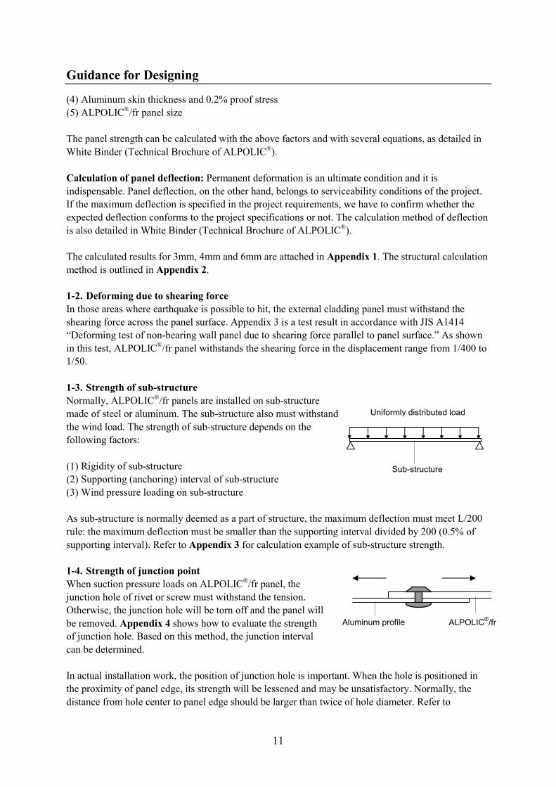
1-3. Strength of sub-structure
Normally, ALPOLIC®/fr panels are installed on sub-structure
made of steel or aluminum. The sub-structure also must withstand
the wind load. The strength of sub-structure depends on the
following factors:
(1) Rigidity of sub-structure
(2) Supporting (anchoring) interval of sub-structure
(3) Wind pressure loading on sub-structure
As sub-structure is normally deemed as a part of structure, the maximum deflection must meet L/200
rule: the maximum deflection must be smaller than the supporting interval divided by 200 (0.5% of
supporting interval). Refer to Appendix 3 for calculation example of sub-structure strength.
1-4. Strength of junction point
When suction pressure loads on ALPOLIC®/fr panel, the
junction hole of rivet or screw must withstand the tension.
Otherwise, the junction hole will be torn off and the panel will
be removed. Appendix 4 shows how to evaluate the strength
of junction hole. Based on this method, the junction interval
can be determined.
In actual installation work, the position of junction hole is important. When the hole is positioned in
the proximity of panel edge, its strength will be lessened and may be unsatisfactory. Normally, the
distance from hole center to panel edge should be larger than twice of hole diameter. Refer to
Sub-structure
Uniformly distributed load
ALPOLIC®/fr Aluminum profile

Guidance for Designing
12
Appendix 4 for further detail.
Note: In order to prevent from galvanic corrosion of ALPOLIC®/fr, use aluminum or stainless steel
rivet, bolt or screw for joining. When ALPOLIC®/fr is connected to different metal, lay a coating film
25 microns or thicker on the metal.
2. Thermal expansion
The thermal expansion ratio of ALPOLIC®/fr is the same as aluminum. Therefore, temperature change
will not cause a movement between ALPOLIC®/fr and aluminum extrusions. However, because
thermal expansion of steel and concrete is smaller, a certain extent of movement is anticipated in long
panel between ALPOLIC®/fr panels and these structural materials. This movement is normally as
small as 1-3mm, but it must be relieved with a suitable method.
Thermal expansion & contraction
Material Expansion ratio
(/°C)
Elongation
per 1m per 50°C
ALPOLIC®/fr 24×10
-6 1.2mm
Aluminum 24×10-6 1.2mm
Steel 12×10-6 0.6mm
Concrete 12×10-6 0.6mm
Acrylic sheet 50-90×10-6 2.5-4.5mm
Acrylic sheet, on the contrary, has a larger expansion rate. When acrylic sheet is adhered on
ALPOLIC® panel, the adhesion must permit some movement of acrylic sheet.
The drawing indicates an example of loose hole to relieve a possible movement between
ALPOLIC®/fr panel and sub-structure made of steel.
3. Thermal insulation
When ALPOLIC®/fr is used for external wall cover, the thermal
insulation of overall wall system will be evaluated.
The heat transmits by three mechanisms of radiation, convection
and conduction. The heat transmission dealt with external wall is
a sum composed of these mechanisms. When temperature
difference exists between outdoor and indoor atmosphere, the
heat flows from the higher temperature to the lower temperature,
through the heat transfer from air to wall (I), heat conduction
inside the wall (II) and heat transfer from wall to air (III). The
overall heat flow process is called heat transmission and
expressed with K-value (kcal/m2h°C) or U-value (W/(m
2K).
The heat transmission through overall wall system is a sum of each component of wall materials from
the outer surface of ALPOLIC®/fr to the inner surface of interior. Generally speaking, ALPOLIC
®/fr
panel itself does not have a sufficient thermal insulation effect as an external wall, but the air space
Heat Transmission
t1
t2
d / C
Ao Ai
Indoor Outdoor
I III II
Loose hole

Guidance for Designing
13
between ALPOLIC®/fr panel and wall
material has a recognizable insulation
effect. The following table is an
example of calculation of total heat
transmission.
Example of calculated heat transmission
through external wall
No Component of heat flow Equation Value, kcal/m2h°C
1' Heat transfer from outer air to ALPOLIC® 1/Ao 0.05
1 Internal heat conduction in ALPOLIC® d1/C1 0.004/0.39=0.01
2 Internal heat transfer in air space d2/C2 0.10
3 Internal heat conduction in brick wall d3/C3 0.115/0.24=0.48
4 Internal heat transfer in air space d4/C4 0.10
5 Internal heat conduction in gypsum board d5/C5 0.012/0.11=0.11
5' Heat transfer from gypsum board to inner air 1/AI 0.13
Total 1/K=1/Ao+Σdi/Ci +1/Ai 1/K=0.98
K=1.02 kcal/m2h°C
(U=1.19 W/(m2K)
K-value: Heat transmission (kcal/m2h)
A o, i : Heat transfer coefficients (kcal/m2h°C)
C: Heat conductivity (kcal/mh°C)
d: Wall thickness (m)
Note: K-value is also called U-value in SI unit in ISO, and converted by K-value
(kcal/m2h)=0.86×U-value (W/(m
2K)).
Refer to Appendix 5 for further details.
4. Waterproofing
In order to ensure waterproofing of joints between panels, normally,
a sealing material is used for joints. The sealing material shall meet
the performance required for the project and also it must be
compatible with ALPOLIC®/fr panel. Silicone, modified silicone,
polysulfide and polyurethane sealant are used for exterior. Among
these materials, silicone sealant is the best in weatherability, but, as
widely known, it stains panel surface. Recently, sealant
manufacturers developed less staining type of silicone, in which the disadvantage of staining is
considerably improved. Refer to Appendix 6 for general comparison among sealing materials.
Regarding the joint design such as joint width and thickness, please follow the sealant manufacturer’s
specifications.
Actual sealing work at site is also important. Improper work will affect not only the aesthetic
appearance of installed panel but also the waterproofing performance of the joint. Therefore, the
sealing work must be conducted carefully, based on the instructions from sealant manufacturers. For
the typical sealing procedures, refer to Fabrication and Installation.
Indoor Outdoor
1
2
4
3
5
5'
1'
1: ALPOLIC/fr
2: Air space 100mm
3: Brick wall 115mm
4: Air space 50mm
5: Gypsum board 12mm

Guidance for Designing
14
When rubber gasket is used for joint, the waterproofing will not be perfect, taking its long-term
durability into consideration. Therefore, a secondary-waterproofing device may be provided behind
joint to ensure the perfect waterproofing.
5. Panel layout and special panel detail
(1) Coating direction of Metallic Colors and Sparkling Colors
In case of Metallic Colors and Sparkling Colors, there is a
slight color difference between standing vertically (like
portrait) and horizontally (like landscape) due to the coating
direction. This slight color difference is subtle but perceptible
from some angle after installation. Therefore, in case of
traverse and parallel coating directions are co-existing in an
area, the color difference must be carefully checked in
advance.
In the shown example, it is likely that the color difference
between Panel A and B is perceptible from some angle in case
of Metallic and Sparkling Colors.
Stone Series requires the similar attention, because it consists of small grain pattern with directional
arrangement. The similar check is necessary for Stone Series in advance.
In case of Solid Colors (No-metallic Colors), the above color difference is negligible. Solid Color
panels can be laid out with different coating direction. It is because of the smoother and the finer
coating of ALPOLIC®/fr derived from Die Coating.
(2) Bending limit
There are two types of bending methods: by press brake and by 3-roll bender. By means of press brake,
the minimum bendable limit of ALPOLIC®/fr is about 80-100 mm in radius. By means of 3-roll
bender, it is 250 to 300 mm in radius, depending on the diameter of the bending roll. Please refer to
Fabrication and Installation for details.
(3) Special panel detail
Special shaped panels such as 3-dimension panels and combined panels are often required. Whenever
we face to such complicated panels, we have to study how to embody the shape without degrading the
advantages of ALPOLIC®/fr. Sometimes we have to ask some modification on the original design for
compromise. Several types of these panels are shown in Fabrication and Installation.
6. Lightning
In the event that a lightning should strike ALPOLIC®/fr panel instead of lightning rod, what will
happen on the panel and the building. When the aluminum skin is connected to the ground earth, the
electricity will be discharged to the ground earth and nothing will happen in the vicinity of the struck
panel, although the struck panel itself might be damaged with the enormous magnitude of lightning
impact. Refer to Appendix 7 for further details.
Panel B
Window Panel A
Panel A
Coating direction

Guidance for Designing Appendix 1
15
Structural strength of ALPOLIC®/fr
The maximum stress exerting in aluminium skin of ALPOLIC/fr can be calculated with the following
equation:
Stress = B·w·b2 / t
2
Where, b: panel width or height, whichever shorter side
B: coefficient dependent on a/b ratio (panel width/panel height) and supporting
condition, as shown in White Binder P. 10.
w: wind pressure (N/mm2 or 10
-6×N/m
2 or 10
-3×kPa)
t2: square of apparent thickness of ALPOLIC
®, given in the following table:
The relevant values to ALPOLIC®/fr 3mm, 4mm and 6mm are given as follows:
ALPOLIC®/fr t
2 (mm
2) 0.2% proof stress
3mm 6.33 152 N/ mm2
4mm 9.25 152 N/ mm2
6mm 15.17 152 N/ mm2
When the maximum stress calculated with the above equation does not exceed 0.2% proof stress (yield
stress), aluminium skins are still within elastic range and permanent deformation will not occur.
Note: Regarding details of the above calculation method, refer to White Binder, in which structural
calculation methods are explained for general purpose.
The maximum deflection of ALPOLIC/fr panel, on the other hand, can be calculated with the
following equation:
Deflection = A·w·b4 / EAPtAP
3
Where, b: panel width or height, whichever shorter side
A: coefficient dependent on a/b ratio (panel width/panel height) and supporting
condition, as shown in White Binder P. 12.
w: wind pressure (N/mm2 or 10
-6×N/m
2 or 10
-3×kPa)
EAP: flexural elastic modulus of ALPOLIC/fr
tAP: thickness of ALPOLIC/fr
EAPtAP3 values are given as follows:
ALPOLIC®/fr EAP (N/mm
2) EAPtAP
3 (N·mm)
3mm 49000 1323×103
4mm 39800 2546×103
6mm 29100 6287×103
Tables 1-6 are the calculated results for ALPOLIC/fr 3mm, 4mm and 6mm. The condition marked
with “>” indicates that the maximum stress exceeds 0.2% proof stress (yield stress) of aluminum skin
3105-H14 (152 N/mm2). Stiffener will be required in this condition. In other range, where the

Guidance for Designing Appendix 1
16
calculated stress is lower than 152 N/mm2, the panel will withstand the condition without stiffener.
ALPOLIC®/fr thickness Supporting condition
Table 1 4mm 4-side fixed
Table 2 4mm 4-side simply supported
Table 3 6mm 4-side fixed
Table 4 6mm 4-side simply supported
Table 5 3mm 4-side fixed
Table 6 3mm 4-side simply supported
If you require other cases, which is not shown in the tables, please inquire to our office. We will
provide separate calculation reports.

Guidance for Designing Appendix 1
17
Table 1. ALPOLIC®/fr 4mm, 4-side fixed
Premise
Thickness: ALPOLIC/fr 4mm
Supporting condition: 4-side fixed
Stiffener: None
Maximum stress (N/mm2) w, kPa Panel width Panel length (a, mm) (kg/m
2) (b, mm) 900 1200 1500 1800 2100 2400 2700 3000 >3000
1.0 600 18 19 19 19 19 19 19 19 19 (102) 900 27 37 42 44 44 44 44 44 44 1200 37 48 62 70 75 77 78 78 78 1500 42 62 75 93 106 114 119 121 122 1.5 600 26 29 29 29 29 29 29 29 29 (153) 900 40 55 62 65 66 66 66 66 66 1200 55 72 93 106 113 116 117 117 117 1500 62 93 112 140 159 > 171 > 178 > 181 > 182 >
2.0 600 35 39 39 39 39 39 39 39 39 (204) 900 54 73 83 87 88 88 88 88 88 1200 73 96 123 141 150 155 > 156 > 156 > 156 > 1500 83 123 150 187 > 212 > 228 > 237 > 242 > 243 >
2.5 600 44 48 49 49 49 49 49 49 49 (255) 900 67 91 104 109 109 109 109 109 109 1200 91 120 154 > 176 > 188 > 194 > 195 > 195 > 195 > 1500 104 154 > 187 > 233 > 265 > 285 > 296 > 302 > 304 >
3.0 600 53 58 58 58 58 58 58 58 58 (306) 900 81 110 125 131 131 131 131 131 131 1200 110 144 185 > 211 > 225 > 232 > 234 > 234 > 234 > 1500 125 185 > 225 > 280 > 318 > 342 > 356 > 363 > 365 >
Note: “>” indicates that the maximum stress exceeds 0.2% proof stress (yield stress) of aluminum skin
3105 H14 (152 N/mm2). Stiffener will be required in this range.
Maximum deflection (mm) w, kPa Panel width Panel length (a, mm) (kg/m2) (b, mm) 900 1200 1500 1800 2100 2400 2700 3000 >3000 1.0 600 1 1 1 1 1 1 1 1 1 (102) 900 4 5 7 7 7 7 7 7 7 1200 6 11 16 19 21 23 23 23 23 1500 7 16 27 37 45 50 53 55 56
1.5 600 2 2 2 2 2 2 2 2 2 (153) 900 5 8 10 11 11 11 11 11 11 1200 8 17 24 29 32 34 35 35 35 1500 10 24 41 56 NA > NA > NA > NA > NA >
2.0 600 2 3 3 3 3 3 3 3 3 (204) 900 7 11 13 14 15 15 15 15 15 1200 11 22 32 39 43 NA > NA > NA > NA > 1500 13 32 55 NA > NA > NA > NA > NA > NA >
2.5 600 3 4 4 4 4 4 4 4 4 (255) 900 9 14 16 18 18 18 18 18 18 1200 14 28 NA > NA > NA > NA > NA > NA > NA > 1500 16 NA > NA > NA > NA > NA > NA > NA > NA >
3.0 600 4 4 4 4 4 4 4 4 4 (306) 900 11 16 20 21 22 22 22 22 22 1200 17 34 NA > NA > NA > NA > NA > NA > NA > 1500 20 NA > NA > NA > NA > NA > NA > NA > NA >

Guidance for Designing Appendix 1
18
Table 2. ALPOLIC®/fr 4mm, 4-side simply supported
Premise
Thickness: ALPOLIC/fr 4mm
Supporting condition: 4-side simply supported
Stiffener: None
Maximum stress (N/mm2) w, kPa Panel width Panel length (a, mm) (kg/m2) (b, mm) 900 1200 1500 1800 2100 2400 2700 3000 >3000 1.0 600 19 24 26 28 29 29 29 29 29 (102) 900 25 37 47 53 56 59 62 66 66 1200 37 45 62 76 87 95 99 103 117 1500 47 62 70 92 110 126 138 148 182 >
1.5 600 28 36 39 42 44 44 44 44 44 (153) 900 38 56 70 80 85 89 94 99 99 1200 56 67 92 113 130 142 149 155 > 175 > 1500 70 92 105 137 165 > 189 > 208 > 223 > 274 >
2.0 600 38 47 52 56 58 58 58 58 58 (204) 900 50 75 94 107 113 119 125 131 131 1200 75 89 123 151 173 > 190 > 198 > 206 > 234 > 1500 94 123 140 183 > 220 > 252 > 277 > 297 > 365 >
2.5 600 47 59 64 69 73 73 73 73 73 (255) 900 63 93 117 134 141 149 156 > 164 > 164 > 1200 93 112 154 > 189 > 216 > 237 > 248 > 258 > 292 > 1500 117 154 > 175 > 229 > 275 > 315 > 346 > 371 > 456 >
3.0 600 57 71 77 83 88 88 88 88 88 (306) 900 76 112 141 160 > 169 > 178 > 187 > 197 > 197 > 1200 112 134 185 > 227 > 260 > 285 > 297 > 309 > 350 > 1500 141 185 > 210 > 275 > 331 > 377 > 415 > 445 > 547 >
Note: “>” indicates that the maximum stress exceeds 0.2% proof stress (yield stress) of aluminum skin
3105 H14 (152 N/mm2). Stiffener will be required in this range.
Maximum deflection (mm) w, kPa Panel width Panel length (a, mm) (kg/m2) (b, mm) 900 1200 1500 1800 2100 2400 2700 3000 >3000 1.0 600 4 6 6 7 7 7 7 7 7 (102) 900 11 19 24 29 31 32 34 37 37 1200 18 36 54 68 81 90 95 100 109 1500 24 54 87 123 153 180 202 221 NA >
1.5 600 6 8 9 10 11 11 11 11 11 (153) 900 17 28 37 43 46 49 52 55 55 1200 28 54 80 102 121 136 142 NA > NA > 1500 37 80 131 185 NA > NA > NA > NA > NA >
2.0 600 9 11 12 14 14 14 14 14 14 (204) 900 23 37 49 57 61 65 69 73 73 1200 37 72 107 137 NA > NA > NA > NA > NA > 1500 49 107 175 NA > NA > NA > NA > NA > NA >
2.5 600 11 14 16 17 18 18 18 18 18 (255) 900 28 46 61 72 76 81 NA > NA > NA > 1200 46 90 NA > NA > NA > NA > NA > NA > NA > 1500 61 NA > NA > NA > NA > NA > NA > NA > NA >
3.0 600 13 17 19 20 22 22 22 22 22 (306) 900 34 56 73 NA > NA > NA > NA > NA > NA > 1200 55 108 NA > NA > NA > NA > NA > NA > NA > 1500 73 NA > NA > NA > NA > NA > NA > NA > NA >

Guidance for Designing Appendix 1
19
Table 3. ALPOLIC®/fr 6mm, 4-side fixed
Premise
Thickness: ALPOLIC/fr 6mm
Supporting condition: 4-side fixed
Stiffener: None
Maximum stress (N/mm2) w, kPa Panel width Panel length (a, mm) (kg/m2) (b, mm) 900 1200 1500 1800 2100 2400 2700 3000 >3000 1.0 600 11 12 12 12 12 12 12 12 12 (102) 900 16 22 25 27 27 27 27 27 27 1200 22 29 38 43 46 47 47 47 47 1500 25 38 46 57 65 69 72 74 74 1.5 600 16 18 18 18 18 18 18 18 18 (153) 900 25 33 38 40 40 40 40 40 40 1200 33 44 56 64 69 71 71 71 71 1500 38 56 68 85 97 104 108 111 111
2.0 600 21 24 24 24 24 24 24 24 24 (204) 900 33 45 51 53 53 53 53 53 53 1200 45 58 75 86 92 94 95 95 95 1500 51 75 91 114 129 139 145 148 148
2.5 600 27 30 30 30 30 30 30 30 30 (255) 900 41 56 63 66 67 67 67 67 67 1200 56 73 94 107 114 118 119 119 119 1500 63 94 114 142 162 > 174 > 181 > 184 > 185 >
3.0 600 32 35 36 36 36 36 36 36 36 (306) 900 49 67 76 80 80 80 80 80 80 1200 67 88 113 129 137 142 142 142 142 1500 76 113 137 171 > 194 > 208 > 217 > 221 > 222 >
Note: “>” indicates that the maximum stress exceeds 0.2% proof stress (yield stress) of aluminum skin
3105 H14 (152 N/mm2). Stiffener will be required in this range.
Maximum deflection (mm) w, kPa Panel width Panel length (a, mm) (kg/m2) (b, mm) 900 1200 1500 1800 2100 2400 2700 3000 >3000 1.0 600 0 1 1 1 1 1 1 1 1 (102) 900 1 2 3 3 3 3 3 3 3 1200 2 5 7 8 9 9 9 9 9 1500 3 7 11 15 18 20 21 22 23 1.5 600 1 1 1 1 1 1 1 1 1 (153) 900 2 3 4 4 4 4 4 4 4 1200 3 7 10 12 13 14 14 14 14 1500 4 10 17 23 27 30 32 33 34
2.0 600 1 1 1 1 1 1 1 1 1 (204) 900 3 4 5 6 6 6 6 6 6 1200 4 9 13 16 17 18 19 19 19 1500 5 13 22 30 36 40 43 45 46
2.5 600 1 1 1 1 1 1 1 1 1 (255) 900 4 6 7 7 7 7 7 7 7 1200 6 11 16 20 22 23 23 23 23 1500 7 16 28 38 NA > NA > NA > NA > NA >
3.0 600 1 2 2 2 2 2 2 2 2 (306) 900 4 7 8 9 9 9 9 9 9 1200 7 14 20 24 26 27 28 28 28 1500 8 20 33 NA > NA > NA > NA > NA > NA >

Guidance for Designing Appendix 1
20
Table 4. ALPOLIC®/fr 6mm, 4-side simply supported
Premise
Thickness: ALPOLIC/fr 6mm
Supporting condition: 4-side simply supported
Stiffener: None
Maximum stress (N/mm2) w, kPa Panel width Panel length (a, mm) (kg/m2) (b, mm) 900 1200 1500 1800 2100 2400 2700 3000 >3000 1.0 600 12 14 16 17 18 18 18 18 18 (102) 900 15 23 29 33 34 36 38 40 40 1200 23 27 38 46 53 58 60 63 71 1500 29 38 43 56 67 77 84 91 111 1.5 600 17 22 24 25 27 27 27 27 27 (153) 900 23 34 43 49 52 54 57 60 60 1200 34 41 56 69 79 87 91 94 107 1500 43 56 64 84 101 115 127 136 167 >
2.0 600 23 29 31 34 36 36 36 36 36 (204) 900 31 46 57 65 69 73 76 80 80 1200 46 55 75 92 106 116 121 126 142 1500 57 75 85 112 134 153 > 169 > 181 > 222 >
2.5 600 29 36 39 42 44 44 44 44 44 (255) 900 38 57 71 81 86 91 95 100 100 1200 57 68 94 115 132 145 151 157 > 178 > 1500 71 94 107 139 168 > 192 > 211 > 226 > 278 >
3.0 600 35 43 47 51 53 53 53 53 53 (306) 900 46 68 86 98 103 109 114 120 120 1200 68 82 113 138 158 > 174 > 181 > 188 > 214 > 1500 86 113 128 167 > 202 > 230 > 253 > 272 > 334 >
Note: “>” indicates that the maximum stress exceeds 0.2% proof stress (yield stress) of aluminum skin
3105 H14 (152 N/mm2). Stiffener will be required in this range.
Maximum deflection (mm) w, kPa Panel width Panel length (a, mm) (kg/m2) (b, mm) 900 1200 1500 1800 2100 2400 2700 3000 >3000 1.0 600 2 2 3 3 3 3 3 3 3 (102) 900 5 7 10 12 12 13 14 15 15 1200 7 15 22 28 33 37 38 40 44 1500 10 22 35 50 62 73 82 89 107 1.5 600 3 3 4 4 4 4 4 4 4 (153) 900 7 11 15 17 19 20 21 22 22 1200 11 22 33 41 49 55 58 61 66 1500 15 33 53 75 93 109 123 134 NA >
2.0 600 3 5 5 6 6 6 6 6 6 (204) 900 9 15 20 23 25 26 28 30 30 1200 15 29 43 55 65 73 77 81 88 1500 20 43 71 100 124 NA > NA > NA > NA >
2.5 600 4 6 6 7 7 7 7 7 7 (255) 900 11 19 25 29 31 33 35 37 37 1200 19 36 54 69 82 92 96 NA > NA > 1500 25 54 89 125 NA > NA > NA > NA > NA >
3.0 600 5 7 8 8 9 9 9 9 9 (306) 900 14 22 30 35 37 39 42 45 45 1200 22 44 65 83 NA > NA > NA > NA > NA > 1500 30 65 106 NA > NA > NA > NA > NA > NA >

Guidance for Designing Appendix 1
21
Table 5. ALPOLIC®/fr 3mm, 4-side fixed
Premise
Thickness: ALPOLIC/fr 3mm
Supporting condition: 4-side fixed
Stiffener: None
Maximum stress (N/mm2) w, kPa Panel width Panel length (a, mm) (kg/m2) (b, mm) 900 1200 1500 1800 2100 2400 2700 3000 >3000 1.0 600 26 28 28 28 28 28 28 28 28 (102) 900 39 53 61 64 64 64 64 64 64 1200 53 70 90 103 110 113 114 114 114 1500 61 90 109 136 155 > 166 > 173 > 177 > 178 > 1.5 600 39 42 43 43 43 43 43 43 43 (153) 900 59 80 91 95 96 96 96 96 96 1200 80 105 135 154 > 165 > 170 > 171 > 171 > 171 > 1500 91 135 164 > 204 > 232 > 250 > 260 > 265 > 267 >
2.0 600 51 57 57 57 57 57 57 57 57 (204) 900 79 107 121 127 128 128 128 128 128 1200 107 140 180 > 206 > 219 > 226 > 227 > 227 > 227 > 1500 121 180 > 219 > 273 > 310 > 333 > 346 > 354 > 355 >
Note: “>” indicates that the maximum stress exceeds 0.2% proof stress (yield stress) of aluminum skin
3105 H14 (152 N/mm2). Stiffener will be required in this range.
Maximum deflection (mm) w, kPa Panel width Panel length (a, mm) (kg/m2) (b, mm) 900 1200 1500 1800 2100 2400 2700 3000 >3000 1.0 600 2 3 3 3 3 3 3 3 3 (102) 900 7 11 13 14 14 14 14 14 14 1200 11 22 31 37 41 43 45 45 45 1500 13 31 53 72 NA > NA > NA > NA > NA > 1.5 600 4 4 4 4 4 4 4 4 4 (153) 900 10 16 19 21 21 21 21 21 21 1200 16 32 47 NA > NA > NA > NA > NA > NA > 1500 19 47 NA > NA > NA > NA > NA > NA > NA >
2.0 600 5 5 6 6 6 6 6 6 6 (204) 900 14 21 25 27 28 28 28 28 28 1200 21 43 NA > NA > NA > NA > NA > NA > NA > 1500 25 NA > NA > NA > NA > NA > NA > NA > NA >

Guidance for Designing Appendix 1
22
Table 6. ALPOLIC®/fr 3mm, 4-side simply supported
Premise
Thickness: ALPOLIC/fr 3mm
Supporting condition: 4-side simply supported
Stiffener: None
Maximum stress (N/mm2) w, kPa Panel width Panel length (a, mm) (kg/m2) (b, mm) 900 1200 1500 1800 2100 2400 2700 3000 >3000 1.0 600 28 35 38 41 43 43 43 43 43 (102) 900 37 55 68 78 82 87 91 96 96 1200 55 65 90 110 126 139 145 151 171 < 1500 68 90 102 134 161 < 184 < 202 < 217 < 267 < 1.5 600 41 52 56 61 64 64 64 64 64 (153) 900 55 82 103 117 124 130 137 144 144 1200 82 98 135 166 < 190 < 208 < 217 < 226 < 256 < 1500 103 135 153 < 201 < 242 < 276 < 303 < 325 < 400 <
2.0 600 55 69 75 81 85 85 85 85 85 (204) 900 74 109 137 156 < 165 < 174 < 183 < 192 < 192 < 1200 109 131 180 < 221 < 253 < 278 < 289 < 301 < 341 < 1500 137 180 < 204 < 267 < 322 < 368 < 404 < 434 < 533 <
Note: “>” indicates that the maximum stress exceeds 0.2% proof stress (yield stress) of aluminum skin
3105 H14 (152 N/mm2). Stiffener will be required in this range.
Maximum deflection (mm) w, kPa Panel width Panel length (a, mm) (kg/m2) (b, mm) 900 1200 1500 1800 2100 2400 2700 3000 >3000 1.0 600 8 11 12 13 14 14 14 14 14 (102) 900 22 36 47 55 59 63 66 71 71 1200 36 69 103 131 155 174 183 192 209 1500 47 103 168 237 NA < NA < NA < NA < NA <
1.5 600 12 16 18 20 21 21 21 21 21 (153) 900 33 53 70 83 88 94 99 106 106 1200 53 103 155 NA < NA < NA < NA < NA < NA < 1500 70 155 NA < NA < NA < NA < NA < NA < NA <
2.0 600 16 22 24 26 28 28 28 28 28 (204) 900 44 71 94 NA < NA < NA < NA < NA < NA < 1200 71 138 NA < NA < NA < NA < NA < NA < NA < 1500 94 NA < NA < NA < NA < NA < NA < NA < NA <

Guidance for Designing Appendix 2
23
Structural calculation method of ALPOLIC®/fr panel
1. Structural calculation without stiffener
(1) How to calculate the maximum stress
When wind pressure is working on ALPOLIC/fr panel,
the panel shows some deflection. Simultaneously, some
intensity of stress arises in the panel in order to
withstand the bending force.
Strength design of ALPOLIC/fr assumes that bending
strength of ALPOLIC/fr panel totally depends on
aluminium skins. As far as the stress exerting in
aluminium skin is lower than the permissible stress
(0.2% proof stress or yield stress) of aluminum skin, the
panel is still elastic. Therefore, we confirm whether the
stress is lower or larger than the permissible stress.
This can be expressed with the following equation:
StressM < StressY
Where,
StressM: Maximum stress in aluminum skin
(N/mm2 or kg/mm
2)
StressY: 0.2% proof stress (yield stress) of aluminum skin (N/mm2 or kg/mm
2)
The 0.2% proof stress (yield stress) depends on aluminum material and its tempering condition. In
case of ALPOLIC (3105 H14), the following value is used:
StressY =152 Ng/mm2 (=15.5 kg/mm
2)
The maximum stress exerting in aluminium sheet, depending on the support condition and panel size,
can be calculated with the following equation:
StressM = B·w·b2 / t
2
Where,
b: Panel width or height, whichever shorter side
B: Coefficient dependent on a/b ratio (panel width/panel height)
w: Wind pressure (kPa, kN/ m2 or kg/m
2)
t2: Square of apparent thickness of ALPOLIC/fr, given in the following table:
ALPOLIC/fr t2 (mm
2)
3 mm 6.33
4 mm 9.25
6 mm 15.17
(2) Calculation example of maximum stress
A. Premise
a
b
Stress
Aluminum skin
Core material
Aluminum skin

Guidance for Designing Appendix 2
24
Wind load: 1.5 kPa (1.5 kN/m2 = 153 kg/m
2)
ALPOLIC/fr thickness: 4 mm
Panel size: 1220×2440 mm
Supporting condition: 4-side fixed
B. Result
StressM = B·w·b2 / t
2
Where, a/b=2.0, then B=0.4974 (from Table 1 or White Binder P.10)
StressM = 0.4974×1500×10-6×1220
2 / 9.25
= 120 < 152 N/mm2
Therefore, the panel will withstand the above condition including safety factor 1.26.
(2) How to calculate deflection
The deflection of ALPOLIC/fr panel can be calculated with the following equation:
Deflection = A·w·b4 / (EAP·tAP
3)
Where,
Deflection: Maximum deflection of ALPOLIC panel
b: Panel width or height, whichever shorter side
A: Coefficient dependent on a/b ratio (length/width)
w: Wind pressure (kPa, kN/ m2 or kg/m
2)
EAP: Bending elastic modulus of ALPOLIC/fr (N/mm2 or
kg/mm2)
tAP: Thickness of ALPOLIC/fr (mm)
EAP·tAP3 is given in the following table:
ALPOLIC/fr EAP·tAP3 (N·mm) EAP·tAP
3 (kg·mm)
3 mm 1323×103 135.0×10
3
4 mm 2546×103 259.8×10
3
6 mm 6287×103 641.5×10
3
(4) Calculation example of deflection
A. Premise
Wind load: 1.5 kPa (1.5 kN/m2 = 153 kg/m
2)
ALPOLIC/fr thickness: 4 mm
Panel size: 1220×2440 mm
Supporting condition: 4-side fixed
B. Result
Deflection = A·w·b4 / (EAP·tAP
3)
Where,
a/b=2.0, then A = 0.0277 (from Table 2 or White Binder P.12)
Deflection = 0.0277×1500×10-6×1220
4 / (2546×10
3)
= 36 mm
2. Strength design reinforced with stiffener
As a result of the above calculation, when the maximum stress exceeds the permissible stress of
aluminium skin, or when the maximum deflection exceeds the project requirement, we will study to
Deflection

Guidance for Designing Appendix 2
25
reinforce the panel with stiffener as one of the alternative solutions. In this study, we select a stiffener
and evaluate whether the stiffener withstands the given condition or not. The rigidity of typical
stiffeners are summarised in Table 3.
(1) How to calculate stress
The bending moment over the area B is given with the
following equation:
M = W· a2 / 8 (N·mm)
Where,
W: Wind pressure loaded on the area B
W = w·B
(w : uniform distributed load, N/mm2)
This bending moment is shared by stiffener and
ALPOLIC/fr panel respectively as follows:
Stiffener: M1 = M·I1 / (I1 + I2)
ALPOLIC/fr: M2 = M·I2 / (I1 + I2)
Where,
I1: Moment of inertia of stiffener (refer to Table 3)
I2 : Moment of inertia of ALPOLIC/fr, given with the following equation:
I2 = B·(H3 – h
3) / 12 (mm
4)
B: Length of the area B (mm)
H: ALPOLIC/fr thickness (mm)
h: Thickness of core material, or internal span between aluminium skin sheets (mm)
Then, the bending stress is given with the following equation:
Stress1 = M1 / Z1 (Stress in stiffener)
Stress2 = M2 / Z2 (Stress in ALPOLIC/fr)
Where,
Z1: Section modulus of stiffener (refer to Table 3)
Z2: Section modulus of ALPOLIC/fr, given with the following equation:
Z2 = B· (H3 – h
3) / 6H (mm
3)
Permanent deformation will not occur within the following range:
Stress1 < Stress1Y (for Stiffener)
Stress2 < Stress2Y (for ALPOLIC/fr)
Where,
Stress1Y: 0.2% proof stress (yield stress) of stiffener (refer to Table 3)
StresseY: 0.2% proof stress (yield stress) of aluminium skin of ALPOLIC/fr (152 N/mm2)
(2) Calculation example of stress
A. Premise
a
B
b Stiffener

Guidance for Designing Appendix 2
26
Wind load: 2.5 kPa (=2.5 kN/m2 = 255 kg/m
2)
ALPOLIC/fr thickness: 4 mm
Panel size: 1220×2440 mm
Supporting condition: 4-side fixed
Stiffener: 50×25×2.5mm t, aluminium extrusion (A6063, T5), 2 pieces per panel
B. Moment of inertia and section modulus
Stiffener: I1 = 3.51×104 mm
4
Z1 = 2.81×103 mm
3
ALPOLIC/fr: I2 = B·(H3 – h
3) / 12 = 813×(4
3 -3
3) / 12
= 0.25×104 mm
4
Z2 = B·(H
3 – h
3) / 6H = 813×(4
3 -3
3) / 24
= 1.25×103 mm
3
Stiffener+ALPOLIC/fr: ΣI = I1 + I2 = 3.76×104 mm
4
C. Calculation of stress
Bending moment: M = W· a2 / 8
= 2500×10-6×813×1220
2/ 8 = 37.81×10
4 N·mm
Stiffener’s share: M1 = M·I1 / (I1 + I2)
= 37.81×104× 3.51 / 3.76 = 35.30×10
4
ALPOLIC/fr’s share: M2= M·I2 / (I1 + I2)
= 37.81×104× 0.25/ 3.76 = 2.51×10
4
Bending stress: Stress1= M1 / Z1
= 35.30×10⁴/ 2.81×10
3 = 126 < 147 N/mm
2 (OK)
Stress2= M2 / Z2
= 2.51×10⁴/ 1.25×10
3 = 20 < 152 N/mm
2 (OK)
Therefore, the panel will withstand the above conditions including safety factor 1.17 for
stiffener.
(3) How to calculate deflection
As for the deflection, respective deflection of stiffener and ALPOLIC is calculated first, and then the
total deflection is given as a combined sum.
Deflection of stiffener:
Deflection1 = 5 W· a4 / 384 E1· I1 (mm)
1220
813
2440
25
50
2.5

Guidance for Designing Appendix 2
27
Where,
E1: Elastic modulus of stiffener (=70000 N/mm2)
Deflection of ALPOLIC/fr:
Deflection2 = A·w·b4 / (EAP·tAP
3) (mm)
Combined deflection can be calculated with the following equation:
Deflection = Deflection1× Deflection2 / (Deflection1 + Deflection2) (mm)
(4) Calculation example of deflection
A. Premise (the same conditions as above)
Wind load: 2.5 kPa (=2.5 kN/m2 = 255 kg/m
2)
ALPOLIC/fr thickness: 4 mm
Panel size: 1220×2440 mm
Supporting condition: 4-side fixed
Stiffener: 50×25×2.5mm t, aluminium extrusion (A6063, T5), 2 pieces per panel
B. Deflection
Deflection of stiffener:
Deflection1 = 5 W· a4 / 384 E1· I1
= 5×3000×10-6×813×1220
4/ (384×70000×3.51×10
4)
= 28.6 mm
Deflection of ALPOLIC:
Deflection2 = A· w ·b4 / (EAP· tAP
3)
Where,
a/b=1220/813=1.50, then A=0.0838 (from Table 2 or White Binder P.12)
Deflection2 = 0.0838×3000×10-6×813
4/ (2546×10
3)
= 43.1 mm
Combined deflection:
Deflection = Deflection1× Deflection2 / (Deflection1 + Deflection2)
= 28.6×43.1 / (28.6+43.1)
= 17.2 mm

Guidance for Designing Appendix 2
28
Table 1 Coefficient B for calculation of stress
Support condition Equation and B value
2-side simply supported
and 2-side free
StressM = 0.75·w·b
2 / t
2
2-side fixed and 2-side
free
StressM = 0.5·w·b
2 / t
2
StressM = B·w·b2 / t
2
a/b 1 1.2 1.4 1.6 1.8 2.0 3.0
4-side simply supported
B 0.2874 0.3762 0.4530 0.5172 0.5688 0.6102 0.7134
StressM = B·w·b2 / t
2
a/b 1 1.2 1.4 1.6 1.8 2.0 >2.0
4-side fixed
B 0.3078 0.3834 0.4356 0.4680 0.4872 0.4974 0.5000
Note: The above is an excerpt from White Binder P.10. Refer to White Binder for other cases.
Table 2 Coefficient A for calculation of deflection
Support condition Equation and A value
2-side simply supported
and 2-side free
Deflection = 0.156·w·b
4 / (EAP·tAP
3)
2-side fixed and 2-side
free
Deflection = 0.0313·w·b
4 / (EAP·tAP
3)
Deflection = A·w·b4 / (EAP·tAP
3)
a/b 1 1.2 1.4 1.6 1.8 2.0 3.0 >3.0
4-side simply supported
A 0.044 0.062 0.077 0.0906 0.1017 0.1110 0.1335 0.1422
Deflection = A·w·b4 / (EAP·tAP
3)
a/b 1 1.2 1.4 1.6 1.8 2.0 >2.0
4-side fixed
A 0.0138 0.0188 0.0226 0.0251 0.0267 0.0277 0.0284
Note: The above is an excerpt from White Binder P.12. Refer to White Binder for other cases.
b
b
a
b
a
b
b
b
a
b
a
b

Guidance for Designing Appendix 2
29
Table 3. Rigidity of Various Stiffeners
Stiffener / Material
(Unit weight)
Moment of inertia
(IX, mm4)
Section modulus
(ZX, mm3)
0.2% proof
stress
(N/mm2)
Aluminium extrusion
40×20×2.0mmt
6063S-T5
(640g/m)
IX = 1.44×10⁴
ZX = 1.44×10³ 147 N/mm
2
Aluminium extrusion
50×25×1.5mmt
6063S-T5
(600g/m)
IX = 2.34×10⁴
ZX = 1.87×10³ 147 N/mm
2
Aluminium extrusion
50×25×2.0mmt
6063S-T5
(800g/m)
IX = 2.96×10⁴
ZX = 2.36×10³ 147 N/mm
2
Aluminium extrusion
50×25×2.5mmt
6063S-T5
(1000g/m)
IX = 3.51×10⁴
ZX = 2.81×10³ 147 N/mm
2
Aluminium extrusion
40×20×2.0t
6063S-T5
(640g/m)
IX = 4.45×10⁴
ZX = 2.22×10³ 147 N/mm
2
Aluminium extrusion
50×25×1.5t
6063S-T5
(600g/m)
IX = 7.01×10⁴
ZX = 2.80×10³ 147 N/mm
2
Aluminium extrusion
50×25×2.0t
6063S-T5
(800g/m)
IX = 9.01×10⁴
ZX = 3.60×10³ 147 N/mm
2
Aluminium extrusion
50×25×2.5t
6063S-T5
(1000g/m)
IX = 10.85×10⁴
ZX = 4.34×10³ 147 N/mm
2
Aluminum sheet
60×30×3.0t
1100-H24
(970g/m)
IX = 2.80×10⁴ ZX = 1.35×10
3 118 N/mm
2
2.0t 40
20
2.5t
50
25
1.5t 50
25
2.0t
50
25
1.5t
50
25
2.0t 50
25
2.5t 50
25
2.0t 40
20
30
60 3.0

Guidance for Designing Appendix 2
30
Fig. 1 Fixation method of stiffener
ALPOLIC/fr panel reinforced with stiffener - from reverse side
Example A
Example B
Rivet
Aluminum m angle
VHB tape
Stiffener
Aluminum flange
Stiffener

Guidance for Designing Appendix 3
31
Deforming test due to shearing force parallel to panel surface
1. Test method
The test was held in accordance with JIS A1414 “Deforming test of non-bearing wall panel due to
shearing force parallel to panel surface.”
(1) Specimen
1150×2300 Tray type panel
(Panel depth: 30mm)
Material: ALPOLIC 4mm
(2) Test apparatus
The test apparatus is shown in
Fig. 1. The specimen is fixed
onto L30×30×3mm angle of
the holder with tapping screw.
Bolt M16 is equipped at one
corner to apply a shearing
force parallel to the panel
surface.
(3) Test method
Tighten the bolt M16 until the
measurement point D1 reaches
P1=1/400, P2=1/300, P3=1/200,
P4=1/150, P5=1/100, P6=1/75
and P7=1/50. P shows a ratio of
horizontal displacement to
panel height. Observe the
following items:
A: Deformation and remaining
deflection of the specimen and
fixing points.
B: Noise of breakage
C: Peel-off or de-lamination of
finishing material.
D: Crack or gap penetrating the
panel and fixation points.
Fig. 1 Test apparatus

Guidance for Designing Appendix 3
32
2. Test result
(1) Displacement and panel deflection
Displacement ratio (P) Initial 1/400 1/300 1/200 1/150 1/100 1/75 1/50
Displacement (mm)
D1 0 6 8 11 16 23 31 46
D2 - 0 0 0 0 0 0 0
D3 - -1 -2 -1 -1 -1 -2 -1
D4 - -3 -4 -5 -6 -9 -11 -16
D5 - 0 0 1 1 3 4 6
Deflection (mm)
A - 0 0 0 0 0 0.8 1.0
B - 0 0 0 0 0 0.5 0.5
C - 0 0 0 0.5 0.5 2.0 3.0
Note: The positions of
measurement points are shown
in Fig. 2.
(2) Observation during and after the
test
The panel, flange and fixation
point with tapping screw was
normal during and after the test.
The displacement was absorbed
in the panel deflection, which
was completely restored to the
original position when the
displacement was eliminated
after the test. Any problem was
not observed in other assemblies
of the tray type panel.
Fig. 2, Measurement points
Guidance for Designing Appendix 4
33
L
1.0 kPa
Strength of sub-structure
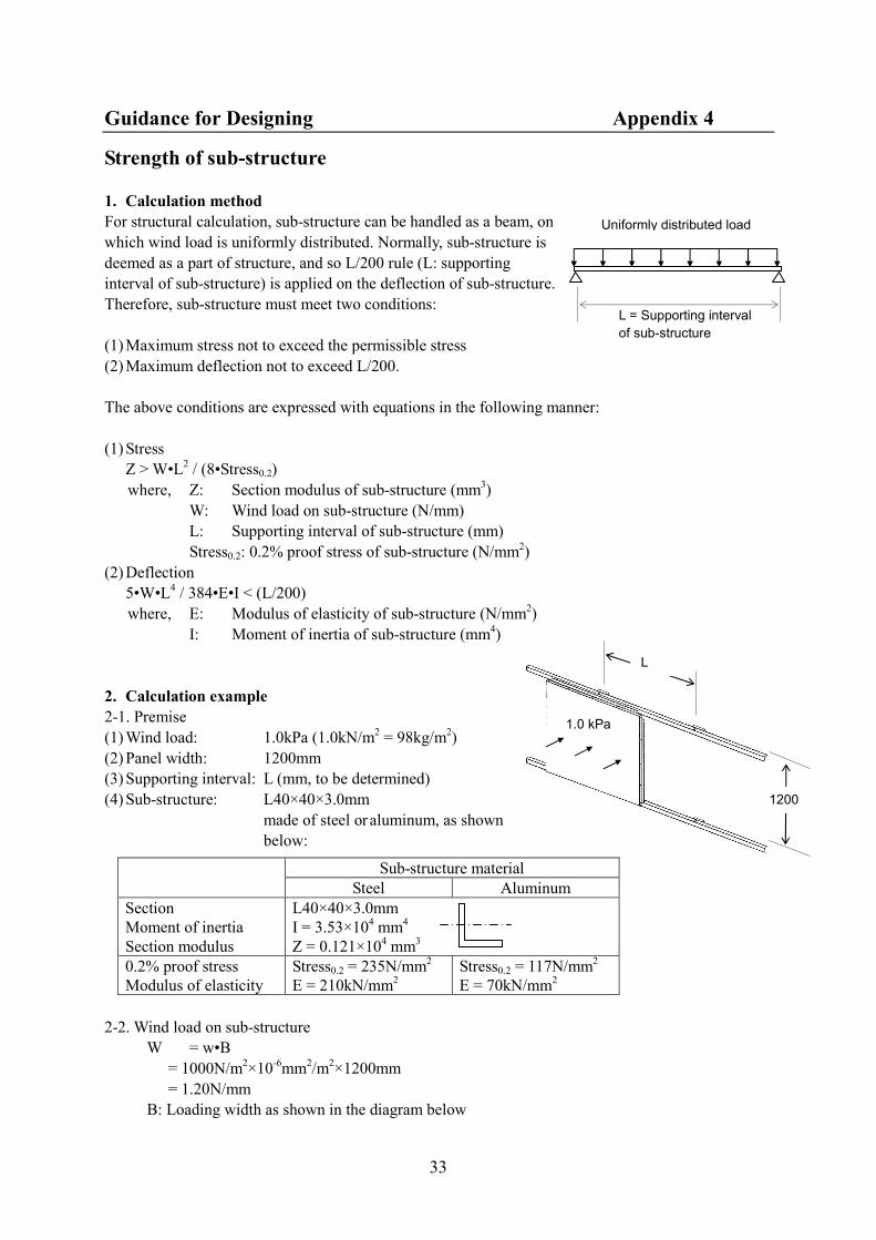
1. Calculation method
For structural calculation, sub-structure can be handled as a beam, on
which wind load is uniformly distributed. Normally, sub-structure is
deemed as a part of structure, and so L/200 rule (L: supporting
interval of sub-structure) is applied on the deflection of sub-structure.
Therefore, sub-structure must meet two conditions:
(1) Maximum stress not to exceed the permissible stress
(2) Maximum deflection not to exceed L/200.
The above conditions are expressed with equations in the following manner:
(1) Stress
Z > W•L2 / (8•Stress0.2)
where, Z: Section modulus of sub-structure (mm3)
W: Wind load on sub-structure (N/mm)
L: Supporting interval of sub-structure (mm)
Stress0.2: 0.2% proof stress of sub-structure (N/mm2)
(2) Deflection
5•W•L4 / 384•E•I < (L/200)
where, E: Modulus of elasticity of sub-structure (N/mm2)
I: Moment of inertia of sub-structure (mm4)
2. Calculation example
2-1. Premise
(1) Wind load: 1.0kPa (1.0kN/m2 = 98kg/m
2)
(2) Panel width: 1200mm
(3) Supporting interval: L (mm, to be determined)
(4) Sub-structure: L40×40×3.0mm
made of steel or aluminum, as shown
below:
Sub-structure material
Steel Aluminum
Section
Moment of inertia
Section modulus
L40×40×3.0mm
I = 3.53×104 mm
4
Z = 0.121×104 mm
3
0.2% proof stress
Modulus of elasticity
Stress0.2 = 235N/mm2
E = 210kN/mm2
Stress0.2 = 117N/mm2
E = 70kN/mm2
2-2. Wind load on sub-structure
W = w•B
= 1000N/m2×10
-6mm
2/m
2×1200mm
= 1.20N/mm
B: Loading width as shown in the diagram below
L = Supporting interval
of sub-structure
Uniformly distributed load
1200

Guidance for Designing Appendix 4
34
2-3. In case of steel sub-structure
[Stress]
Z > W•L2 / (8•Stress0.2)
0.121×10⁴ > 1.20×L
2/(8×235)
L < 1377 mm
[Deflection]
5•W•L4 / 384•E•I < (L/200)
5×1.20×L4/ 384×210000×3.53×10
4< (L/200)
L < 1333 mm
To meet both stress and deflection conditions, L < 1333 mm. Namely, the supporting interval must be
smaller than 1333 mm.
2-4. In case of aluminum sub-structure
[Stress] Z > W•L2 / (8•Stress0.2)
0.121×10⁴ > 1.20×L
2/(8×117)
L < 971 mm
[Deflection] 5•W•L4 / 384•E•I < (L/200)
5×1.20×L4/ 384×70000×3.53×10
4< (L/200)
L < 925 mm
To meet both stress and deflection conditions, L < 925 mm. Namely, the supporting interval must be
smaller than 925 mm.
2-5. Conclusion
The calculated results are summarised as follows:
Sub-structure material Supporting interval
Steel < 1333 mm
Aluminum < 925 mm
3. Support intervals of sub-structure for general purpose
The following charts are calculation results for suitable intervals of L-40×40×3mm made of steel or
aluminum. This calculation is based on the following premise:
Sub-structure material Steel L-40×40×3mm
Galvanised or coated with
rust-preventive paint
AluminumL-40×40×3mm
Alloy: 6063 T5
Moment of inertia I = 3.53×104 mm
4 I = 3.53×10
4 mm
4
Section modulus Z = 0.121×104 mm
3 Z = 0.121×10
4 mm
3
Permissible stress
(including safety factor=1.25)
Stress P = 210N/mm2 Stress P = 118N/mm
2
Modulus of elasticity E = 210kN/mm2 E = 70kN/mm
2
PW=1200
PW=1200
B=1200
ALPOLIC panel Sub-structure

Guidance for Designing Appendix 4
35
Steel L-40×40×3mm Aluminum L-40×40×3mm
0.0
0.5
1.0
1.5
2.0
2.5
3.0
3.5
4.0
300 600 900 1200 1500 1800 2100
Supporting In terval (mm)
Wind Load (kPa)
PW=1500
PW=900
PW=1200
0.0
0.5
1.0
1.5
2.0
2.5
3.0
3.5
4.0
600 600 900 1200 1500 1800 2100
Supporting In terv al (mm)
Wind Load (kPa)
PW=1500
PW=900
PW=1200

Guidance for Designing Appendix 5
36
Strength of junction hole
Rivet, bolt/nut and tapping screw are quite often used for
junction between ALPOLIC® panels and aluminum
profiles. When tensile force loads on the junction point,
stress will arise in the junction hole of ALPOLIC® panel.
In order to evaluate the maximum elastic limit of junction
hole, test was performed. The results are shown in the
table below:
To utilize this table, we convert the stress to tensile force
with the following equation:
F = Stress × t × D
Where, Stress: Maximum elastic stress (N/mm2)
F: Maximum tensile force (N)
t: Thickness of ALPOLIC®
D: Hole diameter
Calculation example:
Premise: ALPOLIC® 305, D = 4 mm, e = 8 mm,
Result: F = Stress × t × D = 48×3×4 = 576 N per junction point
Max. elastic stress (N/mm2) Max. tensile force, F (N) Hole
diameter
D (mm)
Hole center to
panel edge
e (mm)
3mm 4mm 6mm 3mm 4mm 6mm
5 5 21 23 18 320 430 530
10 48 44 38 720 880 1150
15 55 46 40 820 920 1210
10 9 20 21 17 590 820 1000
19 38 33 25 1150 1330 1530
30 39 38 25 1170 1530 1470
It is understood from the above table that, if the hole position is in the proximity of edge, the hole
strength lessens to one half of its original strength. In order to ensure a reasonable strength of junction
hole, the distance from the center of hole to the edge (e) should be larger than double of hole-diameter
(D): namely, e > 2×D.
ALPOLIC® Aluminum profile
Test method for junction hole

Guidance for Designing Appendix 6
37
Heat Transmission of External Cladding
1. Mechanism of heat transmission
The heat transmits by three mechanisms of radiation, convection and conduction:
Radiation: The heat transmission by a thermal energy, evolved from an object, reaching another
object, to increase the latter temperature.
Convection: The heat transmission by movement of fluid, like air or water. When a part of fluid is
warmed, and then, the part of fluid moves upward due to the lightened density.
Conduction: The internal heat transmission in solid material.
2. Heat conduction
Among these mechanisms, the heat transmission dealt with
external claddings is primarily dependent on the heat
conduction of the wall materials.
When a temperature difference exists between both sides of
wall, heat flows from the higher temperature end to the lower
temperature end by heat conduction, and the speed of heat
flow is defined as the heat conductivity, which is expressed by
the following equation:
Q = (L/ d) • (t1-t2)
where
Q: Total heat flow by heat transmission (kcal/m2h)
L: Heat conductivity (kcal/mh°C)
t1, 2: Surface temperature of wall (°C)
d: Wall thickness (m)
The heat conductivity of ALPOLIC/fr is given as a combined conductivity of aluminum and core
material, and it is a relatively small value, compared with aluminum and steel. The heat conductivity
of various wall materials is summarized in Table 1.
Table 1, Heat Conductivity of Various Wall Materials
Materials Heat
Conductivity
kcal/mh°C
Materials Heat
Conductivity
kcal/mh°C
Materials Heat
Conductivity
kcal/mh°C
ALPOLIC/fr 3mm 0.43 Float Glass 0.86 Gypsum Board 0.11
ALPOLIC/fr 4mm 0.39 Granite 2.50 Rock Wool 0.035
ALPOLIC/fr 6mm 0.35 Concrete 1.40 Glass Wool 0.035
Aluminum Sheet 180.0 Mortar 1.30 Polyurethane Foam 0.035
Steel Sheet 39.0 Brick 0.24 Styrofoam 0.030
3. Heat transmission
Apart from the heat conduction through wall materials, there is another heat flow in the interface
between the wall and the adjacent air. This heat flow of interface, caused by a concurrent
occurrence of heat radiation, convection and conduction, is called the heat transfer.
Fig. 1, Heat Conduction
t1
t2
d
External wall

Guidance for Designing Appendix 6
38
Fig. 3, Heat Transmission of Actual Wall
1: ALPOLIC/fr 4mm
2: Air space 100mm
3: Brick wall 115mm
4: Air space 50mm
5: Gypsum board 12mm
1
2
4
3
5
Indoor Outdoor
5'
1'
When there is a temperature difference in atmosphere between
both sides of wall, the heat flows from the higher temperature
to the lower temperature, through the heat transfer (air to
wall), heat conduction inside the wall and heat transfer (wall
to air). The overall heat flow process is called the heat
transmission.
This process can be expressed by the following equation:
Q = K• (t1-t2)
K = 1 / (1/Ao + d/L+ 1/Ai )
Where
Q: Total heat flow by heat transmission (kcal/m2h)
K: Heat transmission coefficient (U Value, kcal/m2h°C)
t1, 2: Atmospheric temperature around wall (°C)
Ao, i : Heat transfer coefficients (kcal/m2h°C)
L: Heat conductivity (kcal/mh°C)
d: Wall thickness (m)
The above K-value, called the heat transmission coefficient,
indicates the easiness of heat flow through the wall. The
lower the K-value is, the thermal insulation of the wall
system becomes better.
This value is also called U-value and expressed in W/(m2• K)
in the SI unit in accordance with ISO. The values can be
converted each other by the following equation:
W/(m2• K)×0.86 = kcal/m
2h°C
4. Heat transmission of actual wall
The heat transmission coefficient of actual wall system, as
shown in Fig. 3, can be calculated by summing up each
component of heat flow, from the outer surface of
ALPOLIC/fr panel to the inner surface of interior material.
Refer to Table 2.
Table 2, Example of Calculation of Heat Transmission Coefficient
No. Component of heat flow Equation Value, kcal/m2h°C
1' Heat transfer from outer air to ALPOLIC/fr 1/Ao 0.05
1 Internal heat conduction in ALPOLIC/fr d1/L1 0.004/0.39=0.01
2 Internal heat transfer in air space d2/L2 0.10
3 Internal heat conduction in brick wall d3/L3 0.115/0.24=0.48
4 Internal heat transfer in air space d4/L4 0.10
5 Internal heat conduction in gypsum board d5/L5 0.012/0.11=0.11
5' Heat transfer from gypsum board to inner air 1/AI 0.13
Total 1/K=1/Ao+Σdi/Li +1/Ai 1/K=0.98
K=1.02 kcal/m2h°C
Fig. 2, Heat Transmission
t1
t2
d/L
Ao Ai
External
wall
Indoor Outdoor

Guidance for Designing Appendix 6
39
Generally, the heat transmission coefficient of actual wall system can be expressed with the
following equation:
1/K = 1/Ao+Σd i/Li +1/AI
Where, d i /Li : Heat conduction of each wall materials or heat transfer of air space
3. Heat transmission coefficient of various wall system
By means of the above equation, the heat transmission coefficient can be calculated for various
types of wall systems. In order to clarify the insulation effect of ALPOLIC/fr, the heat transmission
coefficient, K-value or U- value, was calculated for some typical wall systems, in which the
components constituting the wall system were selected among the following alternatives:
Wall component
1. External cladding (1) ALPOLIC/fr
(2) Solid aluminum panel
(3) Float glass
2. Thermal insulation (1) None
(2) Glass wool 25mm
(3) Glass wool 50mm
3. Structural wall or fireproof
material
(1) RC wall
(2) Brick wall
(3) Gypsum board 16+16mm
4. Interior material (1) None
(2) Gypsum board 12mm
1
2 4
3
Indoor Outdoor

Guidance for Designing Appendix 6
40
Table 3, Heat transmission coefficient of external wall (1)
Heat Transmission
Coefficient (U Value)
Heat Transmission
Coefficient (U Value)
Wall System
(Thickness, mm)
kcal/m2h°C (W/m2•K)
Wall System
(Thickness, mm)
kcal/m2h°C (W/m2•K)
ALPOLIC/fr
3mm only
5.4 (6.2) Heat Absorbing
Float Glass
Bronze 6mm
5.0 (5.8)
ALPOLIC/fr
4mm only
5.3 (6.1) High
Performance
Reflective
Glass 6mm
3.9-4.6 (4.6-5.4)
ALPOLIC/fr
6mm only
5.1 (5.9) Double Glazing
Glass,
Reflective
Glass 6mm +
Airspace 12mm
+FL6
1.5-2.3 (1.9-2.6)
Aluminum
Sheet 3mm
5.6 (6.5) Polycarbonate
Sheet, Clear
3mm
5.2 (6.0)
Aluminum
Sheet 4mm
5.6 (6.5) ALPOLIC/fr 4
Air Space 50
Gypsum Board
12
2.5 (2.9)
Float Glass
Clear 3mm
5.1 (6.0) Reinforced
Concrete
100mm
4.0
(4.6)
Float Glass
Clear 6mm
5.0 (5.8) Reinforced
Concrete
150mm
3.5
(4.1)
ALPOLIC/fr 4
Air Space 100
RC Wall 100
2.8 (3.2) Brick Wall 115
Air Space 50
Gypsum Board
12
1.2 (1.3)

Guidance for Designing Appendix 6
41
Table 3, Heat transmission coefficient of external wall (1)
Heat Transmission
Coefficient (U Value)
Heat Transmission
Coefficient (U Value)
Wall System
(Thickness, mm)
kcal/m2h°C (W/m2•K)
Wall System
(Thickness, mm)
kcal/m2h°C (W/m2•K)
RC Wall 100
Air Space 50
Gypsum Board
12
2.2 (2.5) ALPOLIC/fr 4
Air Space 100
Brick Wall 115
Air space 50
Gypsum Board
12
1.0 (1.2)
ALPOLIC/fr 4
Air Space 100
RC Wall 100
Air Space 50
Gypsum Board
12
1.8 (2.1) ALPOLIC/fr 4
Air Space 75
Glass Wool 25
Brick Wall 115
Air space 50
G. Board 12
0.59 (0.69)
ALPOLIC/fr 4
Air Space 75
Glass Wool 25
RC Wall 100
Gypsum Board
12
0.79 (0.92) ALPOLIC/fr 4
Air Space 50
Glass Wool 50
Brick Wall 115
Air space 50
G. Board 12
0.42 (0.48)
ALPOLIC/fr 4
Air Space 50
Glass Wool 50
RC Wall 100
Air Space 50
G. Board 12
0.50 (0.58) ALPOLIC/fr 4
Air Space 100
Gypsum Board
16, Air Space
50, Gypsum
Board 16
1.5 (1.7)
Brick Wall
115mm
1.5 (1.8) ALPOLIC/fr 4
Air Space 75
Glass Wool 25,
G. Board 16,
Air Space 50,
G. Board 16
0.72 (0.83)
ALPOLIC/fr 4
Air Space 100
Brick Wall 115
1.3 (1.5) ALPOLIC/fr 4
Air Space 50
Glass Wool 50,
G. Board 16,
Air Space 50,
G. Board 16
0.47 (0.55)
ALPOLIC/fr
3mm
Air Space 100
G. Board 16,
Air Space 50,
G. Board 16
1.48 (1.72) Aluminum
Panel 3mm
Air Space 100
G. Board 16,
Air Space 50,
G. Board 16
1.49 (1.74)
ALPOLIC/fr
6mm
Air Space 100
G. Board 16,
Air Space 50,
G. Board 16
1.46 (1.69) Aluminum
Panel 4mm
Air Space 100
G. Board 16,
Air Space 50,
G. Board 16
1.49 (1.74)

Guidance for Designing Appendix 7
42
General performance of sealant
Silicone sealant is widely known for its excellent long-term performance such as durability, thermal
resistance and adhesion reliability. The following table shows general comparison among sealing
materials for exterior.
General performance Sealing Materials
Silicone Modified
silicone
Polysulfide Polyuretha
ne
Restoring ability A A-B B B
Degradation Due to aging VS S-M M M
Due to temperature VS S-M M-L M
Shrinkage after filling S S S S
Serviceable temperature (long-term) -40/120°C -30/90°C -20/80°C -20/70°C
Weatherability A A-B A-B B
Fatigue resistance A A-B B A-B
Note 1: A: Excellent B: Good C: Normal
VS: Very small S: Small M: Medium L: Large
Note 2: The above is excerpt from Sealing Material Handbook, Japan Sealant Manufacturers’
Association.
But silicone sealant is also known for its staining problem. Especially, if silicone sealant is applied for
natural stone wall, in which many small cavities exist on the surface, the staining problem becomes
serious.
The following table is excerpt from “Architectural Technology No.4, P.90-93, 1993”, architectural
magazine published in Japan, focusing on the staining tendency of each sealing material. Recently,
silicone sealant manufacturers have developed the less staining silicone sealant. The following table
was prepared before this new type silicone emerged.
Stain Sealing Materials
Silicone Modified
silicone
Polysulfide Polyuretha
ne
Surrounding area Due to dispersed component C A A A
Sealing joint surface Due to dust adhesion C B A C
Due to mold grow B B B B
Color fading Due to UV & sulfur A A B C
(Note) A: No affect, B: Small affect, C: Affect

Guidance for Designing Appendix 8
43
Protection of ALPOLIC/fr Panels against Lightning
1. General understanding
In the event that lightning should strike the ALPOLIC/fr
panel of external cladding, what will happen on the panel
and the building? Generally speaking, external cladding
panels constitute an electric circuit together with the
sub-structure, which is finally connected to the ground earth.
Therefore, it is a general understanding that the lightning
electricity will flow toward the ground through the electric
circuit, and nothing will happen on the panel and the
building.
But, to be safe, we are going to verify the electric behavior
of ALPOLIC/fr panel of external cladding more in detail,
particularly when lightning strikes ALPOLIC/fr panel.
2. Requirements for electric-conducting wire to release lightning electricity
When lightning strikes ALPOLIC panel of external cladding and the electricity flows through the
electric circuit consisting of ALPOLIC panels and their sub-structure, if the electric resistance of the
circuit is low enough, the electricity will pass through the circuit, like a electric-conducting wire,
toward the ground. Thus, in order to act as a suitable electric-conducting wire to release the lightning
electricity, the electric resistance of external cladding and sub-structure must be low enough. In
accordance with JIS A 4201 "The protection of structures against lightning," the requirements for
electric-conducting wire of lightning rod is standardized as follows:
(1) To provide every wire within 50m interval of perimeter of the building.
(2) The electric resistance of each wire shall be lower than 50 ohm and the overall resistance shall be
lower than 10 ohm.
3. Electric resistance of ALPOLIC panels and sub-structure
According to the above standard, we would like to evaluate
whether the electric resistance is low enough in ALPOLIC
panels and sub-structure system. In order to evaluate the
electric resistance, one model of external cladding was used:
a rectangular solid building of 25m by 25m by 100m high,
as shown in Fig.2.
ALPOLIC cladding and sub-structure are assumed to be
surrounding the whole building. The installation method is
assumed as Fig. 3. Sub-structure, coated steel, is fixed to the
concrete slab with bracket and anchor. ALPOLIC panels are
fixed onto the sub-structure with screw of stainless steel.
Fig. 1, Lightning on ALPOLIC/fr panel
External
cladding
Ground
earth
Lightning rod
25m
25m
100m ALPOLIC
&
sub-structu
re
Fig. 2, Model for calculation

Guidance for Designing Appendix 8
44
As the surfaces of ALPOLIC and sub-structure are coated with paint, both surfaces are electrically
insulated.
Therefore, the electrical connection between ALPOLIC panel and sub-structure will be ensured by
means of junction points by rivets (aluminum) and screws (stainless steel) in this model. Based on the
above assumption, when the contact resistance of these junction points is disregarded, the electric
resistance of ALPOLIC panel and sub-structure from the building top and to the ground can be
calculated as follows:
Table 1. Calculated electric resistance of external cladding
ALPOLIC
(aluminum skin of
surface side, 0.5mmt)
Sub-structure
(steel, 100×50×2mmt)
Combined resistance
of aluminum and
steel
Specific resistance of
aluminum and steel
4×10⁻⁸ohm·m 10×10
-8 ohm·m -
Sectional area of metals
in the model
0.05m2
(0.5×10-3×25m×4)
0.027m2
(0.2×2×10-3×66pcs.)
-
Electric resistance from
top to bottom
0.8×10⁻⁴ ohm 3.7×10
-4 ohm 0.66×10
-4 ohm
As shown in the above table, it is confirmed that the calculated resistance of external cladding is very
low, compared with the standard value of 10ohm.
4. Survey at ALPOLIC project
To confirm the above calculation, we held a survey at actual ALPOLIC project (total ALPOLIC area is
300m2, as shown in Fig.4), to measure the actual electric resistance between two ALPOLIC panels of
different distance. We also measure the resistance between ALPOLIC panel and the principal earth of
the building. The result is shown in Table 2.
Fig. 3, Installation details
@=1.5m Junction by rivet
Bracket & anchor
Vertical
sub-structure
Junction by screw
ALPOLIC panel
Horizontal
sub-structure

Guidance for Designing Appendix 8
45
Table 2. Result of survey at actual ALPOLIC project
Measured points Distance
between two
points
Resistance
between two
points
10m 0.2 ohm
20m 0.3 ohm
One ALPOLIC panel to
another ALPOLIC panel
30m 0.2 ohm
10m 0.0 ohm One ALPOLIC panel to the
principal earth of the building 20m 0.2 ohm
5. Difference between ALPOLIC panel and solid aluminum panel
Based on the same model mentioned above, the resistance of solid aluminum panel can be calculated
as follows:
Table 3. Calculated electric resistance of solid aluminum panel
Solid aluminum panel
(aluminum 3.0mmt)
Sub-structure
(steel, 100×50×2mmt)
Combined resistance
of aluminum and
steel
Specific resistance of
aluminum and steel
4×10⁻⁸
ohm·m 10×10-8
ohm·m -
Sectional area of metals
in the model
0.3m2
(3.0×10-3×25m×4)
0.027m2
(0.2×2×10-3×66pcs.)
-
Electric resistance from
top to bottom
0.13×10⁻⁴ohm 3.7×10
-4ohm 0.13×10
-4ohm
From Table 1 and 3, the resistance of ALPOLIC external cladding can be compared with that of solid
aluminum panel as follows:
ALPOLIC Solid aluminum panel
3.0mm
Combined resistance of
aluminum and steel
0.66×10⁻⁴ohm 0.13×10
-4ohm
Compared with the standard of 10ohm and the contact resistance of the junction points, both
resistances are very small and the difference between two seems to be in a negligible range.
Fig. 4, ALPOLIC project where the
survey was held