Embed Size (px)
Citation preview
1
Guidance Document - Continuity of
Waterproofing Systems
February 2017

2
Guidance Document - Continuity of Waterproofing Systems
1. INTRODUCTION
2. DEFINITIONS
3. DESIGN PRINCIPLES
4. CONSIDERATIONS
5. TYPES OF JOINT
6. TYPES OF SEALING SYSTEM
7. DEFECTS – CAUSES AND REMEDIATION
8. RELEVANT STANDARDS AND CODES

3
1. INTRODUCTION This document has been produced to provide guidance on the prevention of water ingress through
the discontinuity of waterproofing systems in below ground structures. One of the key principles laid
out in BS8102:2009 is the need to ensure that waterproofing systems, of any type, should be
continuous where possible. Any break in the waterproofing system or interface between different
systems increases the risk of a defect or failure.
2. DEFINITIONS For the purposes of this document, the following definitions refer:
• Type A (barrier protection) Structure constructed from concrete or masonry, offering only limited protection against the
ingress of water by the nature of its design. Protection is therefore primarily dependent on a
barrier system applied to the structure, combined with serviceable land drainage where
appropriate.
• Type B (structurally integral protection) Designed and constructed in reinforced or pre-stressed concrete to Eurocode 2; or to BS EN
8500 (to minimise water penetration); BS 8102 or to BS EN 1992 part 3 formerly BS 8007 (to
prevent water penetration) dependent on the chosen grade of basement use.
• Type C (drained protection) Constructed from structural concrete (including diaphragm walls) or masonry to minimise the ingress of water. Any water that does find its way into the basement is channelled, collected and discharged within the cavity created through the addition of an inner skin to both walls and floor.
• Concrete bleed A form of segregation where some of the water in the concrete tends to rise to the surface of
the freshly placed material.
• Construction Joint Joint formed in-situ in concrete when continuity is not possible. It can also be the construction
interfaces between masonry, concrete or other building materials.
• Crystallisation The reaction of water meeting “crystallising admixtures” that produces a swelling of the
material which then blocks the capillaries within the curing concrete. This can also be an
additive at concrete batching stage, or a post applied application.
• Expansion Joint Joint that permits relative movement caused by expansion and contraction due to changes of
temperature or moisture.
• “Honeycombing” Voids in the concrete caused by poor compaction and or vibration which does not adequately
allow entrapped air to escape a concrete mix.
• Hydration Chemical reaction between cement and water.
• Hydrostatic Head Water pressure, expressed as an equivalent depth of water.
• Hydrostatic Pressure Water pressure exerted as a result of hydrostatic head/pressure created by water.
• Kicker

4
Small concrete up stand, cast above floor level to position wall or column formwork for the
next construction level.
• Kicker Less Construction A mechanical means of retaining formwork in position, eliminating a kicker.
• Laitance Is a weak, friable layer on the surface of concrete and sand cement screeds.
• Membrane A barrier that is impervious to water.
• Plastic Cracking Plastic shrinkage cracking is produced when fresh concrete in its plastic state is subjected to
rapid moisture loss.
• Pressure Pressure is a load which is spread across an area, e.g. hydrostatic pressure.
• Protection boards A sturdy sheet boarding applied to external membranes to protect from construction damage and material backfill.
• Render The term ’render’ refers to any applied coat which is made up of a sand: cement mix only, and
can be used for coatings applied internally or externally. It may incorporate water-resisting
admixtures, accelerators, plasticisers or other approved additives.
• Seepage Slow transmission of water through discrete pathways of a structure.
• Shrinkage When a mixture of cement and water hardens, the resultant material occupies a lesser volume
than when in its plastic state, as water is lost. This is due to the contraction or decrease in
volume of the concrete. The time sequence and shrinkage deformation level are influenced
mainly by the start of drying, ambient conditions and the concrete composition.
• Stress The pressure that builds up within the elements of a structure to resist applied loads and/or
pressures.
• Tanking The term ‘tanking’ refers to a pressure resisting waterproofing system that is applied internally
or externally to a structure, which will prevent any lateral penetration of liquid, either by
capillary action or by hydrostatic pressure.
• Waterproof A material or layer that is impervious to the passage of water.
• Waterproofing The application of a material that is impervious to water.
• Water Resistant A material or layer with a high resistance to the passage of water under pressure, but which
is not waterproof.
• Waterstop Material designed to inhibit the transmission of water under pressure through joints in the
structure.
• Water Vapour Water in its gaseous phase, also known as humidity

5
• Water Vapour control
Control of vapour is required as part of waterproofing design.
3. DESIGN PRINCIPLES
BS8102:2009 Code of Practice for the protection of below ground structures against water from the ground, provides guidance on the methods which can be adopted to deal with and prevent the entry of water from the ground into a structure that is below ground level. It is widely referred to and used in basement waterproofing with reference to:
• Adoption of a design team
• Water table classification
• Defects and remedial measures
It also refers to other waterproofing protection known as Type-A (barrier protection) and Type-C
(drained protection) and how they can be combined with Type-B systems where required.
Design should be in accordance with relevant Building Regulations and applicable statutory
requirements.
All elements (including foundations, walls and floors) forming a below ground structure requiring
waterproofing should be suitable for their intended purpose.
Design and build philosophy Generally, design and construction should be kept as simple as possible. Consulting relevant
waterproofing specialists as early as possible and working through details sequentially will help to
avoid unbuildable details on site.
All floors, ceilings and walls below external ground level including the junctions between them, should
be designed to resist the passage of water and moisture to the internal surface. The level of protection
against water and moisture reaching the internal surfaces should be appropriate for the proposed use.
Habitable accommodation should be designed to “Grade 3” as described in BS 8102:2009 – that ‘no
water penetration is acceptable and a dry environment will be provided if maintained by adequate
ventilation’.
Non-habitable areas such as parking areas, storage or plant rooms where the internal finishes are not
readily damaged by moisture should be designed to a minimum “Grade 2” as described in BS
8102:2009 ‘as no water penetration is acceptable although damp is tolerated’.
Retaining walls used to form elements such as light wells ideally should be designed to provide “Grade 1” protection – defined as ‘Some seepage and damp areas tolerable, dependent on the intended use. Local drainage might be necessary to deal with seepage’. Where there is any doubt about use, the level of protection required for habitable accommodation
should be provided.
Designer: Waterproofing systems should be designed by a Waterproofing Design Specialist who can
demonstrate that they have a suitable level of knowledge for designing waterproofing systems.
The Property Care Association (PCA) provides training for surveyors and designers of underground
waterproofing systems. The Certificated Surveyor in Structural Waterproofing (CSSW) is a recognised
industry qualification which requires an understanding of waterproof systems and the ability to

6
comment on them. The PCA has created a register of Waterproofing Design Specialists (WDS) who
have shown further ability to provide design advice for structural waterproofing.
Several Buildings Insurance companies now specify an individual with CSSW or alternative recognised
qualification as part of a waterproofing design team.
With the publication of the register of Waterproofing Design Specialists, developers, architects and
builders can quickly locate individual practitioners who can assist in the design and planning of
underground waterproofing. This ability will allow them to conform to the recommendation set out
in BS8102: 2009. The availability of the register will ensure that a properly vetted and approved
Waterproofing Design Specialist is available and accessible to the leader of any design team.
The list of Waterproofing Design Specialists can be accessed via:
www.property.care.org/ProGuidance.RWDS.asp
Site Investigation: A site investigation is important as its results will have a bearing not only on the waterproofing options
considered, but also how the structure is designed. Although the findings of a site investigation can
be seen as conclusive, consideration should be given that it is often a ‘snap shot in time’ and conditions
on or around the site may change in the future.
It should be assumed water will come to bear against the full height of the below ground structure at
some time in its life. The risk of future failure of a system may be acceptable for the initial use of the
structure but it may not be acceptable when the system is changed to ‘higher risk’ use later. As such
it may be that designing a system to offer full protection to full height, regardless of any water table
classification, should be considered.
There are some overriding principles that need to be highlighted when selecting the form of
construction and waterproofing system that a site investigation will assist with.
Aspects of gathering site information are dealt with in the subsections that follow but there are some
overriding principles that need to be highlighted when selecting the form of construction and
waterproofing system.
As stated in BS 5930, ‘Investigation of the site is an essential preliminary to the construction of all civil
engineering and building works’. BS EN 1997 provides guidance on geotechnical design. Assessment
of ground conditions is particularly important for basements, since the materials used and the
performance of the finished structure will be greatly influenced by the ground conditions. Several
factors need to be assessed and reference should be made to the above Standards.
It should also be taken in to account that water tables can be seasonal and can fluctuate. The effects
of future developments within a vicinity where, for example, deep piled foundations are to be used
can have future adverse effects, by changing the level of the water table. This should include the
location of any ‘spring line’ which could affect soil hydrology.
Risk Assessment: A risk assessment should be carried out which identifies any possible long-term water pressures, the
effects of surface water percolation, use of external drainage and party wall impact on neighbours.
It should take into consideration the possible effects of climate change, defective water goods, nearby
trees, contaminants; and where external drainage is proposed, the effects dewatering may have on
adjacent structures along with the potential for silting of drainage.

7
Any designs or risk assessments should be carried out by specialists carrying an appropriate level of
Professional Indemnity (P.I) insurance cover.
Water table: The existence of a watercourse or water table and its seasonal position below ground will need to be
established. The site history and name clues such as ‘Pond Lane’, ‘Spring Lane’ or ‘Winterbourne Lane’
can help. Evidence of a flooding site could suggest an impermeable soil or a high or perched water
table.
High water tables present the greatest risk of failure to the waterproofing of a basement and it is
therefore important to identify. A watercourse or water table that rises and falls and the potential for
a perched water table must also be identified. How often and for how long the water table stays high
are also important factors.
If the water table rises briefly – say, after heavy rain – and then immediately falls again, the risk of
water penetration through external waterproofing and then through the structure is less than if the
water table stays high for a much longer period. Consideration should also be given to the effect of
possible planned developments adjacent to or near the site either under consideration or potentially
in the future. Historic information on past flooding is valuable, including any recording of rate of water
ingress. If the water table is variable, then it is advisable to design to the “highest level”.
The likely presence of water and the position of the water table must also be established for
construction purposes. The main contractor may need to lower the water table temporarily to enable
the construction and waterproofing to go ahead. In addition, any lowering of the water table will need
to be maintained until the loads acting on the basement, from either itself or in combination with the
superstructure, are greater than the forces that would be generated by the water pressures as the
water table returns to its original level.
The existence of any aggressive elements in the ground and/or the groundwater must be established
to ensure that the most suitable combination of structure category and waterproofing system is
selected.
More information on water tables and ground water can be found in the PCA document ‘What is
groundwater?’
Ground conditions: The design of the basement should consider all current and likely future ground conditions. The design
of the waterproofing system should consider the likely effects of these ground conditions, including
water, and assume exposure of the basement to full height of water within the design life of the
building.
A summary of common investigations relating to ground conditions along with some useful guidance
is given in the table below.
Ground drainage: The topography of the land and the direction and movement of any groundwater should be
determined as they will have a bearing on any proposals to provide drainage to reduce local
groundwater pressures.
If there are any drains or land drains, their positions and performance should be established. Any new
construction proposals should not interrupt drains that still function unless measures are taken to
redirect them or to intercept the water by a new drainage system.

8
Soil type and conditions: The type of soil can greatly influence the volume of water reaching the basement wall. Free-draining
soils not subject to variability in water tables generally present fewer problems than clays, which tend
to be impermeable.
It is important, therefore, to determine the soil type, in particular its drainage characteristics. It should
be noted that the soil around a basement may not be uniform and therefore care needs to be taken
when assessing its overall characteristics. Such assessment is best left to specialists.
Some soils contain chemicals that may harm both the structure and the waterproofing system. Check
the ground for materials that are detrimental, such as peat, sulphates, chlorides, VOCs and
hydrocarbons.
BS 8102:2009 advises the designer to take account of the presence of, or potential for, natural gases
such as radon and methane, and other gases such as CO2 when considering waterproofing. This is
mentioned so that designers can take note of the perceived risks from radon and advise their clients
accordingly. It should also be noted that high levels of radon can accumulate even where basements
are protected by a waterproofing membrane (that is also effective as a radon barrier), and this may
lead to the installation of a radon management system where the risk assessment, particularly in
existing structures, indicates that legislation might otherwise apply.
When drained, waterproofing systems are a part of a specification, it is important to check with the
relevant bodies / local authorities / utility providers on permitted discharges/consents before deciding
whether to discharge any potential ground water into their drainage systems.
Table 1 – BS8102: 2009

9
Movement risks A change in ground moisture content – caused, for example, by the removal of trees – can result in ground movement and affect the load-bearing capacity of soil and applied waterproofing. Clay and peaty soils are particularly prone to volumetric changes leading to varying foundation pressures and movement. There is risk of ground movement caused by the drying out of the ground due to dry periods and drought (As occurred in 1976). The remains of former buildings or structures on the site need to be assessed. They are best removed to avoid differential movement due to bearing over firmer points. Steeply sloping sites may have high land-slip risks, which should be assessed before proceeding further. Particular care is needed where there are changes in the soil strata that may cause differential foundation movement. Although such matters can be catered for structurally, they do present problems. For example,
although expansion joints are a common solution, they may not be appropriate.
If the risk of movement is high, movement joints should be considered. Where possible, designers
should not attempt to create waterproofed expansion joints but instead should design discrete boxes
that can be separately waterproofed.
Sequence and timing of work It is fundamental that the waterproofing elements of a structure are communicated with all relevant
parties throughout the construction process. For this reason, the waterproof design should take into
consideration the construction stages and timing between them to ensure the result and function of
any installed material is as expected. All parties should be aware of the waterproofing materials that
are introduced at each stage to avoid problematic post installations, miss-installations or potentially
leaving them out altogether.
4. CONSIDERATIONS
Site de-watering: If de-watering of a site is deemed necessary, it should be done to a degree suitable for the proposed
system with due consideration to existing surrounding structures to ensure any potential movement
to the surrounding land as a result of de-watering does not have a detrimental effect. In any case,
specialist advice should be sought. Suggested further points of reading regarding dewatering are:
• CIRIA Document 515. Groundwater control – Design and Practice
• Construction Dewatering and Groundwater Control: New Methods and Applications, 3rd Edition (J. Patrick Powers, 2007)
• Groundwater Lowering in Construction: A Practical Guide (P.M. Cashman and Martin Preene, Ove Arup & Partners, UK, 2001
Ground gases: The likelihood of gases being present can be established from the underlying geological structure, and
guidance for its control may be found in several documents and via official sources on the internet. BS
8102:2009 refers to maps of areas where basic or full protection against radon needs to be provided.
These are contained in the Building Research Establishment (BRE) reports BR211, BR376, BR413 and
the Health Protection Agency (HPA) documents:
• HPA-RPD-033, Indicative Atlas of Radon in England and Wales, 2007, ISBN 978-0-85951-608-2, available from HPA.

10
• HPA-RPD-051, Radon in Dwellings in Scotland: 2008 Review and Atlas, ISBN 978-0-85951-634-1, available from HPA.
• NRPB Documents, Vol 4, No.6, 1993, Radon affected areas: Scotland and Northern Ireland ISBN 085951367X, available from HPA.
Attention is also drawn to the Building Regulations and to further guidance on the characterisation
and remediation of ground gases given in BS 8485. Guidance on measures for large buildings is given
in BRE guidance: Radon protection for new large buildings. In view of health issues concerning radon,
due vigilance should be observed regarding any revisions to these documents and other official
sources.
Methane and other gases are likely to be linked to infill and made-up ground, particularly where large
amounts of organic matter have been buried. Such sites can also present risks from acid wastes,
mineral oil shales, and other fill materials. Some slags and other residues often contain toxic materials
and some furnace ashes may be reactive. The Building Regulations give information on site
preparation and resistance to moisture, and include guidance on ground contaminants.
Structural stability Parts of the building constructed below ground level that form usable spaces should be designed by an Engineer. The existing substrate should be assessed by the Structural Engineer for suitability for the proposed system. The design should consider all imposed loads including:
• Ground movement
• Lateral forces from ground water and retained ground
• Buoyancy
• Loading from other parts of the building
For further guidance refer to The Basement Information Centre Design guide.
CONTINUITY OF WATERPROOFING SYSTEMS
With all types of waterproofing system, it is recommended that contractors who are trained and
experienced in the particular systems used for installation.
TYPE A CONTINUITY
Type A continuity is defined in BS8102:2009, section 8.1.3 which states:
The waterproofing barrier should, in most instances, be continuous around the structure (see 6.2.4).
To maintain the continuity of the barrier, penetrations through walls or floors that are to be protected
(e.g. openings for services, pipes, cables) should be avoided, wherever possible. Where it is essential
to provide such openings, special treatment around the penetration should be provided and reference
should be made to the manufacturer’s instructions and specialist advice. Similarly, where fixings
through the barrier are necessary, the manufacturer’s instructions should be followed.
Movement joints below ground should not be used unless unavoidable; in such cases these should be
waterproofed in accordance with the manufacturer’s instructions.
Where a waterproofing barrier is required for a structure supported on piled foundations, special
consideration should be given to the detailing so that structural continuity is not compromised (see
Figure 5) and reference should be made to the manufacturer’s instructions.

11
TYPE B CONTINUITY
5. TYPES OF JOINT
Construction Joint Construction Joints are designed to spilt areas of the structure into separate concrete sections for work scheduling reasons. Construction Joints require special attention, as these are most commonly associated with leaks.
Construction joints are generally deemed to be a monolithic strong joint in reinforced concrete,
connecting work done on two different days. The reinforcement in construction joints is therefore
continuous through the joint.
The first section has starter bars left protruding so that new reinforcement laps with the old. Vertical concrete surfaces may have a trapezoidal profile or be cast against mesh to provide a mechanical key (as recommended in BS EN 1992- formerly BS8007 and BS8110). Horizontal surfaces ought to be prepared to remove laitance or weak concrete as per BS 8102: 2009 Code of practice for protection of below ground structures against water from the ground. Specialist permanent formwork components are often available and need special consideration to
ensure a watertight seal.
In addition to the above, construction joints can incorporate services or other penetrations, formwork
tie bolts or abutment to other structural elements of differing material nature.
Construction joints can be waterproofed in a variety of ways, such as:
• Hydrophilic strips.
• Injection tubing systems.
• Paste / sprinkle on active slurries.
• Hypalon rubber type strips.
• Passive water bars etc. Induced Contraction Joint Where Induced Contraction Joints are created, it is imperative that the waterproofing provides continuity and is of correct type.
Image: Induced contraction joint

12
Movement Joint A Movement (or Expansion) Joint is an engineered solution to allow shear, compressive and/or tensile
forces in a local area. Typically, this is a separation between two structures, leaving a linear gap with
no structure that needs to be bridged by the waterproofing system; therefore, the waterproofing
system’s resistance to anticipated movement should be considered.
Where possible, movement Joints should be designed to be accessible for maintenance.
Movement joints below ground should not be used unless unavoidable. If the risk of movement is high
and joints are unavoidable, where possible, designers should not attempt to create waterproofed
expansion joints but instead should design discrete boxes that can be separately waterproofed.
Movement joints can also require loading e.g. for screeds, steel plates with sliding bolts etc. It is
imperative to check with a structural engineer for the most appropriate loading for their design.
6. TYPES OF SEALING SYSTEM There are many types of sealing system/solution across all waterproofing system types (A, B and C) as outlined in BS8102:2009. The type of sealing system must be suitable for the waterproofing systems being used. Each waterproofing system must be an independent continuous system.
Construction Joints: Type A and Type C systems can normally cope with construction joints in the concrete structure,
whereas Type B waterproofing systems require additional components to maintain continuity.
Movement Joints: Type A systems should be capable of maintaining continuity whilst accommodating anticipated
movement, or otherwise designed with components to ensure the movement does not damage the
Type A system.
Type C systems are generally not capable of maintaining continuity over Movement Joints. Therefore,
if they cannot be designed with components to overcome this, then they should be designed to avoid
the movement joint.
Type B waterproofing systems require additional components to maintain continuity. Options for
these are listed below.
PASSIVE PVC/Rubber Waterstops PVC/Rubber waterstops can be used to bridge discontinuities in the structure at Construction Joints
or Movement Joints.
Rubber or flexible polyvinyl chloride (PVC) extruded profiles can be cast into the concrete on both
sides of the joint, either at the concrete surface or mid-depth of the concrete section, to form a
physical obstruction to water transmission:

13
Image: External, construction joint waterbar Image: Internal, movement joint waterbar
These are extruded profiles fabricated with junction pieces to provide a linked continuous system
through all the joints or discontinuities within a concrete structure.
Plain web profiles are available for non-moving or low-movement construction and contraction joints.
Profiles incorporating a centre bulk or box are used where there is movement, as in expansion joints.
External waterstop profiles are available and are positioned on the external face of the concrete. These rear-fixed or surface waterstops simplify the shuttering and installation but will resist the passage of water only from the face in which they are installed. Alternatively, they may be cast totally within the site-placed concrete. These are known as internal or
centrally placed waterstops. Internal waterstops will resist the passage of water through a joint from
either face. However, they can be more difficult to install and fix, can be dislodged during casting of
section and are probably best avoided in domestic basements unless great care is taken and the work
properly supervised and inspected.
For all waterstops, the intersections and junctions require welding in situ by competent persons using
tools and jigs provided by the system manufacturer. Pre-formed junctions can be provided by the
system manufacturer.
PVC waterstops are suitable for variable water tables.
Metal Waterstop Steel water bar strips are cast in mid-depth of the concrete section to form a continuous fluid-tight
diaphragm which acts immediately as a physical obstruction to water transmission. Because of this
they are suitable for variable water tables.
These can be passive sections as plain steel or coated with a pressure sensitive adhesive which forms
a chemical bond to the concrete when poured to eliminate water tracking, they can also be active
systems with addition of a hydrophilic coating.
These strips are tied to the formwork and so care must be taken to ensure the fixing method for these
waterstops is compatible with the steel design for that joint.
Image: Metal Waterstop

14
External bonded / clamped strips Sometimes referred to as “Bandage joint systems”, these can be used in new build and remedial work,
internally or externally, depending on buildability.
These consist of strips of synthetic polymer membrane bonded across the joint with a suitable
adhesive or single component cold applied rubber installed across the joint.
Where used internally the component used must be able to withstand negative water pressure.
These solutions can form part of a Type A or Type B waterproofing system. In the case of a dual
system, they cannot be used for both Type A and Type B at the same time, as each waterproofing
system must have a separate line of defence over the joints.
These can often be suitable for movement as well as construction joints.
ACTIVE Hydrophilic strips Hydrophilic strips react on contact with water and will swell to many times their original size in an
unrestrained condition. Within concrete joints they must be fully restrained so that the swell action
exerts a sealing pressure as water pressure increases rather than swelling to seal a void.
They are installed in construction joints once part of the joint has been cast and prepared for the next
pour. Because they are confined in the concrete, when they swell they exert a pressure inside the joint
and therefore block further migration of water.
Image: Waterstop to slab penetration

15
The strips may be wholly of hydrophilic material, or compounded with a rubber, or part of a composite
profile. They can be applied against existing concrete since they avoid the problems of breaking out
to install a conventional rubber or PVC waterstop. The use of water-swellable strips is limited to
construction joints and should never be used for movement joints.
The manufacturer’s minimum dimension of reinforced concrete cover must be followed to suitably
restrain the increase in volume and facilitate sealing pressure.
Hydrophilic products should be kept dry until they are fully cast in place to ensure that no pre-
hydration or swelling takes place.
Polymer Based Hydrophilic polymers are inseparably linked to the carrier material so at maximum swell the material
maintains its square section.
Polymer base hydrophilic strips will return to their original size and shape when dry. Because of this
they can take time to exert full pressure on the surrounding concrete within the joint. Manufacturer’s
should be contacted regarding delayed swell
Sodium bentonite based Sodium bentonite based hydrophilic extrusions can swell many times their dry volume and upon
hydration can change from a solid state to a plastic compound capable of penetrating voids and
cavities.
Sodium Bentonite hydrophilic strips when drying will shrink back within the joint, but not always to its
original form. Because of this they are not suitable for variable water tables, as some seepage may
occur during the swelling process.
Injection Hose Permeable hose or other sections that are installed in the construction joint once part of the joint has
been cast and prepared for the next pour, to facilitate the injection of a specialist sealing resin into
the joint after hardening of the concrete.

16
These consist of a perforated or permeable tube fixed to the first pour of concrete in the construction
joint with both ends attached to fittings connected to the formwork. The tube is cast into the
construction joint.
When the concrete has hardened, a polyurethane resin or other propriety fluid can be injected under
pressure to flow through the tube and, when the exit of the tube is sealed, it flows, under pressure,
out of the perforations into any cracks, fissures or holes in the construction joint. The injected material
then sets to seal all water paths through the joint.
These post injectable systems provide a repairable solution as required in BS8102:2009 to an
otherwise non-maintainable type of waterproofing.
Injection hoses should not be used on their own. An additional measure (e.g. hydrophilic strip) should
be placed in the construction joint as the first protective barrier.
These products are not suitable for use in movement/expansion joints.
Crystallisation Slurries / Cementitious Sealant Crystallisation slurries or cementitious sealant composition applied to the concrete joint at depth in
the section. The materials give rise to crystal growth on contact with water, providing an enhanced
obstruction.
These differ from the previously mentioned systems in that the product consists of cements, fillers
and chemicals to be mixed on site as slurry. The slurry is applied to the face of the first-poured
concrete before the second pour. The waterstopping action results from salt crystallisation, in the
presence of water, within the pores and capillaries of the concrete.
These products are not suitable for use in movement/expansion joints.
They will not stop active water ingress
7. DEFECTS – CAUSES AND REMEDIATION BS8102: 2009 advises that waterproofing design should allow for defects owing to poor workmanship, the inappropriate use of materials, defects owing to the specific properties of the materials used, as well as the form and feasibility of their elected systems. It is therefore essential that the construction methods and materials used are such that:
• Potential defects owing to poor workmanship or the inappropriate use of materials are avoided
• Potential defects owing to the specific properties of the materials used should be recognised and catered for in the design.

17
TYPES AND CAUSES OF DEFECTS The hydration regime of the overall concrete structure requires consideration and in accordance with good concreting practice / standards and current local climatic conditions, i.e. consider the use of heated blankets in extreme cold weather and damp hessian / plastic sheeting / regular misting in conditions of extreme heat. Concrete defects at the joint Poor concrete compaction or crack formation around any construction or movement joint can render the sealing system redundant as the defects in the concrete will let water migrate around the sealing system.
Image: Leaking construction joint
Substrate/surface preparation Substrates should be prepared in accordance with the manufacturer’s recommendation for each different sealing solution. If this is not followed, there is an increased risk of material bond failure and water penetration. Wrong component selection The following parameters should be considered when selecting a sealing solution. Incorrect selection
could lead to the component failure.
• Contaminants – chemical / saline / VOCs / Gases • Water Pressure – absolute / positive / negative • Movement – amount / direction • Ground Water Level – design for full head of water, but accommodating variable levels. • Concrete cover to hydrophilic strips should be confirmed by the manufacturer and per the
dimensions and expansive capacity.
As these systems vary, the manufacturer’s advice on application method should always be followed.
PVC Waterstop weld/joint failure Welding of PVC or rubber waterstops is critical to the performance of the whole system. Welds should be tested before installation to ensure they are watertight. This can be done by mechanical and visual means.
18
Preformed joints should be used where possible to reduce the risk of defects.
Plastic & metal water bars create micro-cracking between the concrete and the water bar allowing possible migration of water although some manufacturers include sealing technology in their system. REMEDIAL OPTIONS Inspection before concreting All sealing systems should be inspected once installed and before the final concrete pour to ensure
they have been placed correctly and will not move during casting.
Injection Hose (if installed) Injection using various resins or grouts can repair a leaking joint. Depending on the type of hose and
injection material used this can be repeated several times if necessary. Care should be taken if drilling
through a waterproofing system. This will need to be repaired correctly to provide continuity.
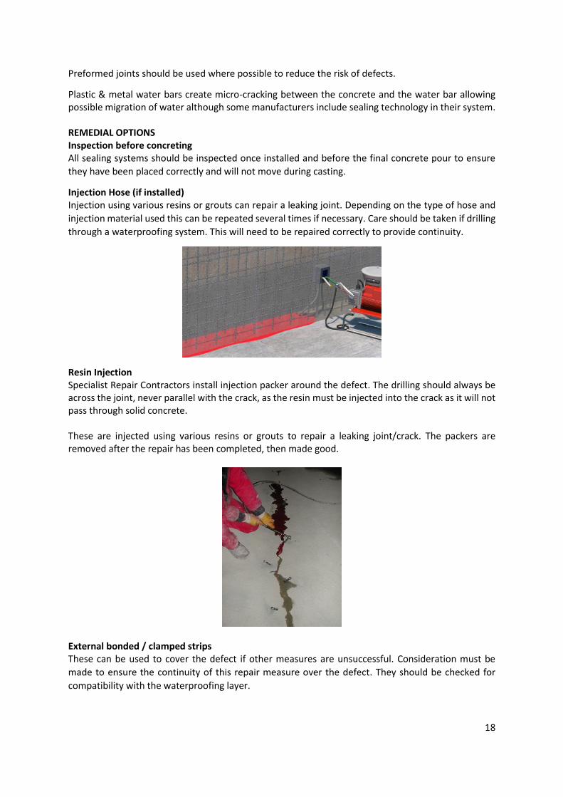
Resin Injection Specialist Repair Contractors install injection packer around the defect. The drilling should always be across the joint, never parallel with the crack, as the resin must be injected into the crack as it will not pass through solid concrete. These are injected using various resins or grouts to repair a leaking joint/crack. The packers are removed after the repair has been completed, then made good.
External bonded / clamped strips These can be used to cover the defect if other measures are unsuccessful. Consideration must be
made to ensure the continuity of this repair measure over the defect. They should be checked for
compatibility with the waterproofing layer.

19
8. RELEVANT STANDARDS AND CODES The following standards, codes and specifications are directly relevant to structural waterproofing:
BS 5930:2015 - Code of practice for ground investigations BS 8002:2015 - Code of practice for earth retaining structures BS 8102: 2009 Code of practice for protection of below ground structures against water from the ground. BS 8485:2015 - Code of practice for the design of protective measures for methane and carbon dioxide ground gases for new buildings BS 8500 Parts 1&2: Concrete - Complementary British Standard to BS EN 206-1 BS 8500-1:2006+A1:2012 Method of specifying and guidance for the Specifier BS 8500-2: 2006+A1:2012 Specification for constituent materials and concrete BS EN 197-1:2000 Cement – Part 1: Composition, specification and conformity criteria for common cements. BS EN 206-1, Concrete, part 1: Specification, performance, production and conformity Eurocode 2: Part 3: Liquid retaining and containing structures BS EN 934-2:2001 Concrete admixtures – Definitions, requirements, conformity, marking and labelling. BS EN 1990: Basis of structural design BS EN 1992-1-1, Eurocode2: Design of concrete structures, part 1-1 general rules and rules for buildings BS EN 1992-3, Eurocode 2: design of concrete structures, liquid retaining and containing structures BS EN 1997-1 Eurocode 7: Geotechnical design, part-1 General rules BS EN 1997-2 Eurocode 7- Geotechnical design Part 2 ground investigation and testing, BSI 2007 PD 5454:2012 - Guide for the storage and exhibition of archival materials Building Regulations This is a guidance note. Where recommendations are made for specific tasks, these are intended to represent 'best practice', i.e.
recommendations that in the opinion of the PCA meet an acceptable level of competence. Although members are not required to follow the
recommendations contained in the note, they should consider the content.
The information contained in this leaflet is given in good faith and believed to be correct. However, it must be stressed that of necessity it is
of a general nature. The precise condition may alter in each individual case and the Association is therefore unable to accept responsibility
for any loss howsoever arising from the use of the information contained herein.
SWG-ConSys3/02/17
This guidance note is written and produced by the PCA Structural Waterproofing Group For further information, contact:
Property Care Association 11 Ramsay Court Kingfisher Way Hinchingbrooke Business Park Huntingdon Cambridgeshire PE29 6FY Tel: 0844 375 4301 Fax: 01480 417587 Email: [email protected] Web: www.property-care.org
© Property Care Association, 2017. All rights reserved.