Embed Size (px)
Citation preview

GUI for Circular and Elliptic Objects Detection in
Digital Images GUI für kreisförmigen und ellipsenförmigen Objektserkennung in den
digitalen Bildern
Veska Georgieva*, Plamen Petrov
†, Antoniya Mihaylova
*,
* Faculty of Telecommunications, Technical University of Sofia,
Sofia, Bulgaria, e-mails: [email protected], [email protected] † Faculty of Mechanical Engineering, Technical University of Sofia,
Sofia, Bulgaria, e-mail: [email protected]
Abstract — The paper presents software for automatic detection of objects with circular and elliptic forms and its
graphical user interface (GUI). It works in the MATLAB environment and uses IMAGE TOOLBOXES defined
functions. The circle objects can be detected and located on the base of Circular Hough Transform (CHT). For
elliptic shape detection the Randomized Hough Transform (RHT) is used. The program proposes also an interactive
option to choose specific parameters and works with the region of interest (ROI) in the processed image. The
proposed GUI can be applied to real medical and microscopy images attempt to make diagnostic more precise. It can
be used in computer vision systems for detection of different objects with circular and elliptic form. The presented
GUI is suitable also to engineering education for studying of this processing.
Zusammenfassung — Der Artikel präsentiert eine Software zur automatischen Erkennung von Objekten mit
kreisförmigen und elliptischen Formen und deren grafische Benutzeroberfläche (GUI). Es funktioniert in der
MATLAB-Umgebung und verwendet IMAGE TOOLBOXES definierte Funktionen. Die Kreisobjekte können auf
der Basis von Circular Hough Transform (CHT) erkannt und lokalisiert werden. Für die elliptische Formdetektion
wird die randomisierte Hough Transform (RHT) verwendet. Das Programm schlägt auch eine interaktive Option vor,
um bestimmte Parameter auszuwählen und arbeitet mit dem interessierenden Bereich (ROI) im verarbeiteten Bild.
Die vorgeschlagene GUI kann auf reale medizinische und mikroskopische Bilder angewendet werden, um die
Diagnose präziser zu machen. Es kann in Computer-Vision-Systeme für die Erkennung von verschiedenen Objekten
mit kreisförmigen und elliptischen Form verwendet werden. Die dargestellte GUI eignet sich auch für die
Ingenieurausbildung für das Studium dieser Verarbeitung.
I. INTRODUCTION
Circle and ellipse detection has been an important task in image processing and pattern recognition. Many approaches have been developed to solve this problem. There are many techniques, which are based on Hough transform (HT) and its variants [1-4]. The HT and its variants have been successfully used in many problems. A major advantage of HT is its insensitivity to imperfect data. HT is able to detect the geometry shapes such as lines, circles and ellipses in various situations. But computationally it is inefficient, which increases with the complexity of shapes [5].
In this paper, we present software for automatic detection of objects with circular and elliptic forms and its graphical user interface (GUI). The circle objects can be detected and located on the base of Circular Hough Transform (CHT). For elliptic shape detection the Randomized Hough Transform (RHT) is used. The algorithm proposes also an interactive option to choose specific parameters and works with the region of interest (ROI) in the processed image.
The remainder of this paper is organized as follows. In the Section 2, the briefly theoretical part is given. In Section 3, the GUI for circle and elliptic objects detection is presented. Section 4 describes tasks carried out from the main program and some experimental results, obtained by computer simulation. Concluding remarks are given in Section 5.
II. THEORETICAL PART
The CHT is useful for detecting circles of known radius as well to detect circles of various radii. This method is based on creating an accumulator matrix of size of the original image to be processed. The local maxima in accumulator space are obtained by voting procedure. Parameter space is defined by the parametric representation used to describe circles in the picture plane [6], which is given by
( ) ( )202
02
yyxxr -+-= . (1)
It implies that the accumulator space is three-dimensional (for three unknown parameters x0, y0 and r) and defines a locus of points (x, y) centered on an origin (x0, y0) with radius r. Points corresponding to x0, y0 and r, which has more votes, are considered to be a circle with center (x0, y0) and radius r.
The advantage of RHT in comparison with classical HT is that some curves can be fully determined by a certain number of points on the curve [7, 8]. For example, a straight line can be determined by two points, and an ellipse (or a circle) can be determined by three points. So the time efficiency can be improved and the storage requirement of the original algorithm will be reduced. The whole process generally consists of three steps [9]:
1. Fit ellipses with randomly selected points. 2. Update the accumulator array and corresponding
scores.
FDIBA Conference Proceedings, vol. 1, 2017 7

3. Output the ellipses with scores higher than some predefined threshold.
The general equation, defined for ellipse in [9] is given by
1222=-+--+- )qy(c)qy)(px(b)px(a (2)
with restriction: 02 >- bac .
RHT starts by randomly selecting three points on the ellipse. By first step the tangents of these three points are founded. They can be found by fitting a straight line using least squares technique for a small window of neighboring pixels.
The next step is to find the intersection points of the tangent lines. With the ellipse parameters determined from previous stage, the accumulator array can be updated correspondingly. The RHT does not keep "grid of buckets" as the accumulator array in comparison with classical HT. Rather, it first calculates the similarities between the newly detected ellipse and the ones already stored in accumulator array. As long as the similarity exceeds some predefined threshold, replace the one in the accumulator with the average of both ellipses and add 1 to its score. Otherwise, initialize this ellipse to an empty position in the accumulator and assign a score of 1.
Once the score of one candidate ellipse exceeds the threshold, it is determined as existing in the image and should be removed from the image and accumulator array so that the algorithm can detect other potential ellipses faster. The algorithm terminates when the number of iterations reaches a maximum limit or all the ellipses have been detected.
III. GUI FOR CIRCULAR AND ELLIPTIC OBJECTS DETECTION
The GUI for circular and elliptic objects detection is presented in Fig.1. It is divided in several areas, where the user applies different settings, concerning different modes for object detection, theirs parameters and areas for universal application.
The area “Select Image” is for entering an image file name with an image file extension. The user can navigate among the folders in the work folder and choose image by using “Open” button.
The Hough transform’s settings are selected in area “Mode”. Two specific modes “Circle” and “Ellipse” are used in regard to implementation of CHT and RHT, respectively.
By selecting of Sobel or Canny operator edge detection can be implemented.
In area “Radius” the maximal and minimal radius of the circles can be determinated. So we can find all the circles with radius r pixels in the range [Rmin, Rmax]. In the case of ellipse detection these parameters are associated with “minMajorAxis“ and “maxMajorAxis“.
In area “Object Polarity” we can indicate whether the circular objects are brighter or darker than the background. If the circular objects are brighter than the background, the option “bright” will be selected. If the circular objects are darker than the background, the option “dark” will be chosen.
The area “Fine Settings” can be used for selecting sensitivity factor and edge gradient threshold. Sensitivity factor is the sensitivity for the circular Hough transform accumulator array, specified as the comma-separated pair consisting of 'Sensitivity' and a nonnegative scalar value in the range [0, 1]. As we increase the sensitivity factor, more circular objects, including weak and partially obscured circles can be detected. Higher sensitivity values also increase the risk of false detection. Edge gradient threshold sets the gradient threshold for determining edge pixels in the image, specified as the comma-separated pair consisting of “Edge Thresh” and a nonnegative scalar value in the range [0, 1]. By “0” we can set the threshold to zero-gradient magnitude. Specifying “1” we can set the threshold to the maximum gradient magnitude.
Fig. 1. Overview of GUI for circular and elliptic objects detection
By setting the threshold to a lower value we can detect more circular objects (with both weak and strong edges). By increasing the value of the threshold, fewer circles with weak edges can be detected.
The area “Features” present the universal application such as saving the result of processing and working with selected region of interest, which can be selected by “Image Cropping”.
After choosing all input information the procedure of processing begins, when the user clicks on button “Start”. Then the final result is shown – original image, and processed images.
IV. TASKS CARRIED OUT FROM THE MAIN PROGRAM
The main algorithm that works behind is shown in Fig.2. By acting of component from GUI a callback-function from the main program can be implemented.
Fig. 2. The flowchart of the main algorithm
Every graphic component can be treated to object. Every object can be referred to handle. The objects referred a complex of attributes, which can be manipulated from the software. The multifarious attributes can be leaved by using in MATLAB environment, such as “Enabled”, “Value”, “Visible”, “On”, ”Off” etc. Every attribute can be enabling in the presence of corresponding handle or reference to the object.
8 FDIBA Conference Proceedings, vol. 1, 2017

By initialization of the graphic application every graphic component can be reiterated to a cycle of events for the MATLAB environment. It submits addresses of the callback-functions, associated to a given event, which are important. By its identification the corresponding callback-function can be called out. The input data validation is one of the important tasks of the main program. If an error concerned with wrong information occurs, the execution is canceled. Another essential purpose of the main program is presenting the input information in appropriate data structures. It is necessary for the next steps in the processing strategy. In this step the processing with appropriate input data is made.
Because of separately processing of images, the program can work with single image as well with image sequence. Input image is the image in which we detect circular or ellipse objects, specified as a grayscale, true color, or binary image.
V. EXPERIMENTAL RESULTS
Some results from simulation, which illustrate the work of the program, will be presented in the following.
The original grayscale microscopy image of embryos of size 570x610 pixels is given in Fig.3. The processed images after edge detection by Sobel operator and CHT are presented in Fig.4 and Fig.5, respectively.
Fig. 3. Original microscopy image of embryos
Fig. 4. Processed microscopy image of embryos after edge detection by
Sobel operator
Fig. 5. Processed microscopy image after CHT with detected all embryos
Some results of elliptic objects detection are presented on
the next figures below. The original microscopy image of
erythrocytes of size 290x174 pixels is given in Fig.6. The
processed images after edge detection by Sobel operator and
RHT are presented in Fig.7 and Fig.8, respectively.
Fig. 6. Original microscopy image of erythrocytes
Fig. 7. Processed microscopy image of erythrocytes after edge detection by Sobel operator
Fig. 8. Processed microscopy image after RHT with detected erythrocytes
for selected parameters
Using the Circular Hough Transform, it is possible to find the coordinates of the centers of the embryos with circle form, as well as their radii.
By processing via Randomized Hough Transform the coordinates of the centroids and angles between the major and minor axis by elliptic objects are found.
The results, obtained by detection of circular and elliptic cells are evaluated by calculating the measures precision, recall and F-measure [10]. The measures were calculated for each image and, then, averaged over all images. The obtained results are given in Table 1.
FDIBA Conference Proceedings, vol. 1, 2017 9
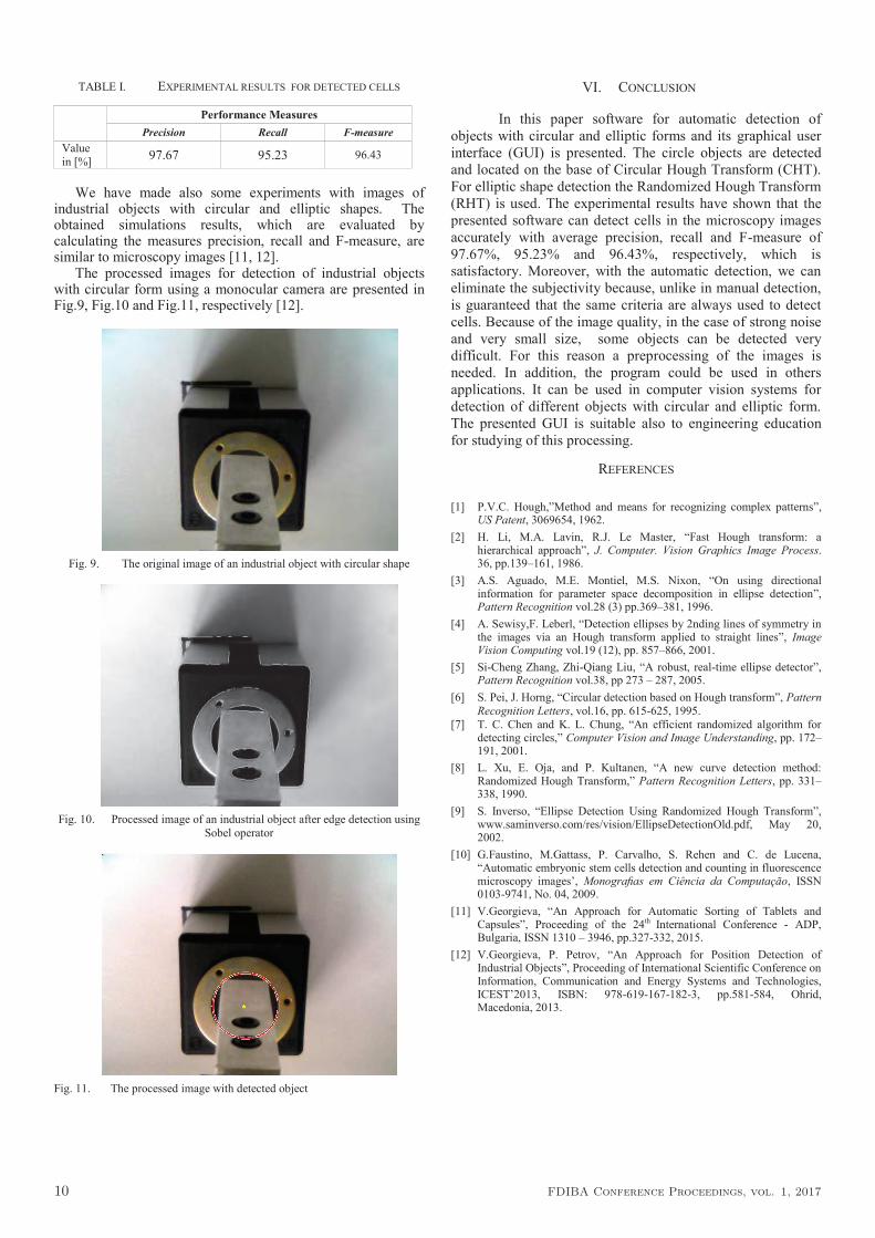
TABLE I. EXPERIMENTAL RESULTS FOR DETECTED CELLS
Performance Measures
Precision Recall F-measure
Value
in [%] 97.67 95.23 96.43
We have made also some experiments with images of
industrial objects with circular and elliptic shapes. The obtained simulations results, which are evaluated by calculating the measures precision, recall and F-measure, are similar to microscopy images [11, 12].
The processed images for detection of industrial objects with circular form using a monocular camera are presented in Fig.9, Fig.10 and Fig.11, respectively [12].
Fig. 9. The original image of an industrial object with circular shape
Fig. 10. Processed image of an industrial object after edge detection using
Sobel operator
VI. CONCLUSION
In this paper software for automatic detection of
objects with circular and elliptic forms and its graphical user
interface (GUI) is presented. The circle objects are detected
and located on the base of Circular Hough Transform (CHT).
For elliptic shape detection the Randomized Hough Transform
(RHT) is used. The experimental results have shown that the
presented software can detect cells in the microscopy images
accurately with average precision, recall and F-measure of
97.67%, 95.23% and 96.43%, respectively, which is
satisfactory. Moreover, with the automatic detection, we can
eliminate the subjectivity because, unlike in manual detection,
is guaranteed that the same criteria are always used to detect
cells. Because of the image quality, in the case of strong noise
and very small size, some objects can be detected very
difficult. For this reason a preprocessing of the images is
needed. In addition, the program could be used in others
applications. It can be used in computer vision systems for
detection of different objects with circular and elliptic form.
The presented GUI is suitable also to engineering education
for studying of this processing.
REFERENCES
[1] P.V.C. Hough,”Method and means for recognizing complex patterns”,
US Patent, 3069654, 1962.
[2] H. Li, M.A. Lavin, R.J. Le Master, “Fast Hough transform: a hierarchical approach”, J. Computer. Vision Graphics Image Process. 36, pp.139–161, 1986.
[3] A.S. Aguado, M.E. Montiel, M.S. Nixon, “On using directional information for parameter space decomposition in ellipse detection”, Pattern Recognition vol.28 (3) pp.369–381, 1996.
[4] A. Sewisy,F. Leberl, “Detection ellipses by 2nding lines of symmetry in the images via an Hough transform applied to straight lines”, Image Vision Computing vol.19 (12), pp. 857–866, 2001.
[5] Si-Cheng Zhang, Zhi-Qiang Liu, “A robust, real-time ellipse detector”, Pattern Recognition vol.38, pp 273 – 287, 2005.
[6] S. Pei, J. Horng, “Circular detection based on Hough transform”, Pattern
Recognition Letters, vol.16, pp. 615-625, 1995.
[7] T. C. Chen and K. L. Chung, “An efficient randomized algorithm for detecting circles,” Computer Vision and Image Understanding, pp. 172–191, 2001.
[8] L. Xu, E. Oja, and P. Kultanen, “A new curve detection method: Randomized Hough Transform,” Pattern Recognition Letters, pp. 331–338, 1990.
[9] S. Inverso, “Ellipse Detection Using Randomized Hough Transform”, www.saminverso.com/res/vision/EllipseDetectionOld.pdf, May 20, 2002.
[10] G.Faustino, M.Gattass, P. Carvalho, S. Rehen and C. de Lucena, “Automatic embryonic stem cells detection and counting in fluorescence microscopy images’, Monografias em Ciência da Computação, ISSN 0103-9741, No. 04, 2009.
[11] V.Georgieva, “An Approach for Automatic Sorting of Tablets and Capsules”, Proceeding of the 24th International Conference - ADP, Bulgaria, ISSN 1310 – 3946, pp.327-332, 2015.
[12] V.Georgieva, P. Petrov, “An Approach for Position Detection of Industrial Objects”, Proceeding of International Scientific Conference on Information, Communication and Energy Systems and Technologies, ICEST’2013, ISBN: 978-619-167-182-3, pp.581-584, Ohrid, Macedonia, 2013.
Fig. 11. The processed image with detected object
10 FDIBA Conference Proceedings, vol. 1, 2017