Embed Size (px)
Citation preview

GTI 5G Function and Performance Test Specification v2.0 – June-2019
1
GTI 5G Device Function
and Performance Test
Specification
http://www.gtigroup.org

GTI 5G Function and Performance Test Specification v2.0 – June-2019
2
5G Device Function and Performance
Test Specification
Version: V2.0
Deliverable Type □ Procedural Document
√ Working Document
Confidential Level √ Open to GTI Operator Members
√ Open to GTI Partners
□ Open to Public
Program 5G eMBB
Working Group Terminal WG
Project Project 1: Sub 6GHz
Task Task-T-PM2-PJ1-10 5G Device Certification and IODT
Source members China Mobile, Anritsu, Keysight, R&S, Datang, Starpoint
Support members Huawei, Qualcomm, Vivo, ZTE
Last Edit Date 16-June-2019
Approval Date

GTI 5G Function and Performance Test Specification v2.0 – June-2019
3
Confidentiality: This document may contain information that is confidential and access to this
document is restricted to the persons listed in the Confidential Level. This document may not be used,
disclosed or reproduced, in whole or in part, without the prior written authorization of GTI, and those
so authorized may only use this document for the purpose consistent with the authorization. GTI
disclaims any liability for the accuracy or completeness or timeliness of the information contained in
this document. The information contained in this document may be subject to change without prior
notice.

GTI 5G Function and Performance Test Specification v2.0 – June-2019
4
Table of Contents
Table of Contents ...................................................................................................................................... 4
1 Scope ................................................................................................................................................ 8
2 Definitions, Symbols and Abbreviations .......................................................................................... 8
3 Reference ......................................................................................................................................... 8
4 Test Environment ............................................................................................................................. 9
4.1 Default Test Environment ..................................................................................................... 9
4.1.1 Special Test Environment ........................................................................................ 10
4.1.2 Cell Configuration ................................................................................................... 10
4.1.3 USIM Parameters .................................................................................................... 11
4.1.4 Common Procedures ............................................................................................... 12
4.2 Applicability for the UE Configuration .............................................................................. 13
5 Basic Function ............................................................................................................................... 13
5.1 PLMN Selection ................................................................................................................. 13
5.1.1 PLMN Selection, Multi-RAT Background, Select the highest priority HPLMN,
Automatic Mode ..................................................................................................................... 13
5.2 Cell Selection ...................................................................................................................... 16
5.2.1 Multi-mode Environment Cell Selection, NR Cell Available .................................. 16
5.2.2 Multi-mode Environment Cell Selection, E-UTRAN Available.............................. 18
5.2.3. Multi-mode Environment Cell Selection, NR Cell Available .................................. 19
5.2.4. Multi-mode Environment Cell Selection, NSA Cell Available ................................ 21
5.2.5 Initial Cell Selection from Power-Up ...................................................................... 23
5.3 RRC connection/connection reconfiguration ...................................................................... 26
5.3.1 RRC connection re-establishment, radio link failure, re-establish to a Prepared
Inter-Freq cell ......................................................................................................................... 26
5.3.2 BWP configuration, downlink and uplink BWP addition /release ........................... 29
5.4 Registration/De-registration ................................................................................................ 30
5.4.1 Initial Registration, SA ............................................................................................ 30
5.5 NSA 33
5.5.1 Multi-mode Environment Cell selection for NSA ................................................... 33
5.5.2 Initial Registration, NSA ......................................................................................... 37
5.5.3 Bandwidth Part Configuration, SCG, EN-DC ......................................................... 39
5.5.4 NSA-RLF ................................................................................................................ 43
5.6 CSI-RS Measurement ......................................................................................................... 57
5.6.1 CSI Reporting Periodic in PUSCH .......................................................................... 57
5.6.2 CSI Reporting Aperiodic in PUSCH ....................................................................... 60
5.6.3 CSI Reporting Aperiodic in PUSCH ....................................................................... 63
5.6.4 CSI-RS Based Intra Frequency Measurements on Neighbour Cell Beams ............. 66
5.6.5 CSI-RS Based Inter Frequency Measurements on Neighbour Cell Beams ............. 70
5.7 RRC Inactive mode cases in SA ......................................................................................... 73
5.7.1 RRC Connected Mode to RRC Inactive Mode and RRC Resume Procedure ......... 73
5.7.2 Periodic RNA Update Procedure in RRC Inactive Mode ........................................ 75
5.7.3 RNA Update in RRC Inactive Mode for Cell Reselection to new RNA cell ........... 78

GTI 5G Function and Performance Test Specification v2.0 – June-2019
5
5.8 Access Barring, Access Class ............................................................................................. 81
5.8.1 Cell Barred while in RRC IDLE State ..................................................................... 81
5.8.2 Access Categories for Different Services ................................................................ 84
5.8.3 Access Barring Check in RRC ................................................................................ 87
6 Mobility ......................................................................................................................................... 90
6.1 Intra-system (NR) Mobility ................................................................................................ 90
6.1.1 Intra-system cell reselection .................................................................................... 90
6.1.2 Intra-system handover ............................................................................................. 93
6.2 Inter-RAT Mobility ........................................................................................................... 107
6.2.1 Inter-RAT cell reselection ...................................................................................... 107
6.2.2 Inter-RAT Handover .............................................................................................. 123
6.2.3 Inter-RAT Redirection Service .............................................................................. 127
6.3 NSA 131
6.3.1 Cell Reselection, from NSA P-Cell to E-UTRAN cell .......................................... 131
6.3.2 Cell Reselection, from E-UTRAN cell to NSA P-Cell .......................................... 135
6.3.3 P-Cell Handover with SCG change, Data continuity............................................. 138
6.3.4 P-Cell Handover with SCG unchange, Data continuity......................................... 141
6.3.5 Data Session continuity, from NSA cell to E-UTRAN cell ................................... 145
6.3.6 Data Session continuity, from E-UTRAN cell to NSA cell ................................... 148
6.3.7 SCG change with P-Cell remain the same, Data continuity .................................. 151
7 Service ......................................................................................................................................... 154
7.1 Voice 154
7.1.1 Redirection from NR to E-UTRAN,MO call,SA mode. .................................. 154
7.1.2 Redirection from NR to E-UTRAN,MT call,SA mode. .................................. 157
7.1.3 VoLTE MO Call with E-UTRAN Cell, UE works in NSA mode. ......................... 160
7.1.4 VoLTE MT Call with E-UTRAN Cell, UE works in NSA mode........................... 162
7.2 Date Transmission ............................................................................................................ 165
8 Roaming ....................................................................................................................................... 165
9 Power Consumption ..................................................................................................................... 165
9.1 Idle Mode .......................................................................................................................... 165
9.1.1 Idle Mode, Power Consumption, Cell Centre, SA ................................................. 165
9.1.2 Idle Mode, Power Consumption, Cell Edge, SA ................................................... 167
9.1.3 Idle Mode, Power Consumption, Cell Centre, NSA .............................................. 169
9.1.4 Idle Mode, Power Consumption, Cell Edge, NSA ................................................ 172
9.1.5 Idle mode with intra Frequency Measurement, Power Consumption .................... 174
9.1.6 Idle mode with inter Frequency Measurement, Power Consumption .................... 177
9.2 RRC Connection mode ..................................................................................................... 179
9.2.1 Connected Mode, Power Consumption ................................................................. 179
9.2.2 Inter Frequency Handover, Power Consumption, LTE to LTE .............................. 189
9.2.3 Inter Frequency Handover, Power Consumption, NR Cell.................................... 193
9.3 Voice (VoLTE/VoNR) ....................................................................................................... 196
9.3.1 VoLTE MO Call with E-UTRAN Cell, Power Consumption ................................ 196
9.3.2 VoNR MO call, Power Consumption .................................................................... 199
9.3.3 VoLTE MT Call with E-UTRAN Cell, Power Consumption ................................. 202

GTI 5G Function and Performance Test Specification v2.0 – June-2019
6
9.4 Data Transmission, Power Consumption .......................................................................... 205
9.4.1 UL Data Transmission, Power Consumption,SA................................................ 205
9.4.2 DL Data Transmission, Power Consumption, SA.................................................. 214
9.4.3 Bi-direction Data Transmission, Power Consumption, SA ................................... 219
9.4.4 UL Data Transmission, Power Consumption,NSA ............................................. 229
9.4.5 DL Data Transmission, Power Consumption, NSA ............................................... 241
9.4.6 Bi-direction Data Transmission, Power Consumption, NSA ................................. 254
9.5 Power Consumption - Inactive Mode ............................................................................... 267
9.5.1 RRC Inactive Mode, Power Consumption, SA ..................................................... 267
9.5.2 RRC Inactive Mode – RNA Update Timer Expiry, Power Consumption .............. 269
9.6 BWP, Power Consumption ............................................................................................... 272
9.6.1 Downlink Data Transmission with different BWP, Power Consumption, SA ....... 272
9.6.2 Uplink Data Transmission with different BWP, Power Consumption, SA ............ 275
9.6.3 Downlink Data Transmission with different BWP, Power Consumption, NSA .... 277
9.6.4 Uplink Data Transmission with different BWP, Power Consumption, NSA ......... 279
10 Data Throughput .......................................................................................................................... 281
10.1 Downlink TCP Throughput............................................................................................... 281
10.1.1 DL Throughput under static channel, DL 256QAM, DL4*4 MIMO..................... 281
10.1.2 DL Throughput under fading channel, DL 256QAM, DL4*4 MIMO ................... 284
10.2 Uplink TCP Throughput ................................................................................................... 287
10.2.1 UL Throughput under static channel, UL 64QAM, DL2*2 MIMO....................... 287
10.2.2 UL Throughput under static channel, UL 256QAM, Single TX, HPUE ............... 291
10.2.3 UL Throughput under static channel, UL 256QAM, UL2*2 MIMO..................... 294
10.3 Bidirectional UDP Throughput ......................................................................................... 297
10.3.1 Bidirectional Throughput under static channel,256QAM, DL 4*4 and UL 2*2
MIMO 297
10.3.2 Bidirectional Throughput under fading channel,256QAM, DL 4*4 and UL 2*2
MIMO 300
10.4 Downlink TCP Throughput, NSA ..................................................................................... 303
10.4.1 DL Throughput under static channel, NSA ........................................................... 303
10.4.2 DL Throughput under fading channel, NSA .......................................................... 307
10.4.3 DL Throughput under static channel on SCG, DL 256QAM, NSA ...................... 311
10.4.4 DL Throughput under fading channel on SCG, NSA ............................................ 315
10.5 Uplink TCP Throughput, NSA ......................................................................................... 319
10.5.1 UL Throughput under static channel, UL 64QAM, NSA ...................................... 319
10.5.2 UL Throughput under static channel, UL 256QAM, NSA .................................... 323
10.5.3 UL Throughput under static channel on SCG, UL 64QAM, NSA ........................ 327
10.5.4 UL Throughput under static channel on SCG, UL 256QAM, NSA ...................... 331
10.6 Bidirectional UDP Throughput, NSA ............................................................................... 335
10.6.1 Bidirectional Throughput under static channel, 256QAM, NSA ........................... 335
10.6.2 Bidirectional Throughput under fading channel, NSA .......................................... 340
10.6.3 Bidirectional Throughput under static channel on SCG, UL 64QAM, NSA ......... 344
10.6.4 Bidirectional Throughput under static channel on SCG, UL 256QAM, NSA ....... 348
10.6.5 Bidirectional Throughput under fading channel on SCG, NSA ............................ 352

GTI 5G Function and Performance Test Specification v2.0 – June-2019
7
11 Latency ......................................................................................................................................... 356
11.1 Latency Basic Tests .......................................................................................................... 356
11.1.1 Control Plane Latency – Basic Test ....................................................................... 356
11.1.2 User Plane Latency – Basic Test............................................................................ 358
12 High Speed Train ......................................................................................................................... 361
13 Beam Management ...................................................................................................................... 361
Appendix A Test Channel Parameters .................................................................................................. 361
Appendix B Document Change Record ............................................................................................... 361
GTI 5G Function and Performance Test Specification v2.0 – June-2019
8
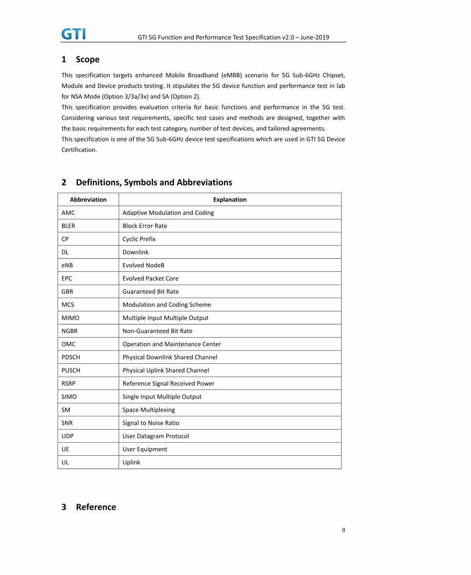
1 Scope
This specification targets enhanced Mobile Broadband (eMBB) scenario for 5G Sub-6GHz Chipset,
Module and Device products testing. It stipulates the 5G device function and performance test in lab
for NSA Mode (Option 3/3a/3x) and SA (Option 2).
This specification provides evaluation criteria for basic functions and performance in the 5G test.
Considering various test requirements, specific test cases and methods are designed, together with
the basic requirements for each test category, number of test devices, and tailored agreements.
This specification is one of the 5G Sub-6GHz device test specifications which are used in GTI 5G Device
Certification.
2 Definitions, Symbols and Abbreviations
Abbreviation Explanation
AMC Adaptive Modulation and Coding
BLER Block Error Rate
CP Cyclic Prefix
DL Downlink
eNB Evolved NodeB
EPC Evolved Packet Core
GBR Guaranteed Bit Rate
MCS Modulation and Coding Scheme
MIMO Multiple Input Multiple Output
NGBR Non-Guaranteed Bit Rate
OMC Operation and Maintenance Center
PDSCH Physical Downlink Shared Channel
PUSCH Physical Uplink Shared Channel
RSRP Reference Signal Received Power
SIMO Single Input Multiple Output
SM Space Multiplexing
SNR Signal to Noise Ratio
UDP User Datagram Protocol
UE User Equipment
UL Uplink
3 Reference

GTI 5G Function and Performance Test Specification v2.0 – June-2019
9
The following documents contain provisions which, through reference in this text, constitute
provisions of the present document.
[1] 3GPP TS 38.104 Base Station (BS) radio transmission and reception
[2] 3GPP TS 38.201 LTE Physical Layer – General Description
[3] 3GPP TS 38.211 Physical Channels and Modulation
[4] 3GPP TS 38.212 Multiplexing and channel coding
[5] 3GPP TS 38.213 Physical layer procedure
[6] 3GPP TS 38.214 Physical Layer – Measurements
[7] 3GPP TS 38.300 Overall description
[8] 3GPP TS 38.321 Medium Access Control (MAC) protocol
[9] 3GPP TS 38.322 Radio Link Control (RLC) protocol
[10] 3GPP TS 38.323 Packet Data Convergence Protocol (PDCP)
[11] 3GPP TS 38.331 Radio Resource Control (RRC)
[12] 3GPP TS 38.401 Architecture description
[13] 3GPP TS 38.410 Ng General aspects and principles
[14] 3GPP TS 38.411 Ng layer 1
[15] 3GPP TS 38.412 Ng signaling transport
[16] 3GPP TS 38.413 Ng Application Protocol (XnAP)
[17] 3GPP TS 38.414 Ng data transport
[18] 3GPP TS 38.420 Xn general aspects and principles
[19] 3GPP TS 38.421 Xn layer 1
[20] 3GPP TS 38.422 Xn signaling transport
[21] 3GPP TS 38.423 Xn application protocol (XnAP)
[22] 3GPP TS 38.424 Xn data transport
[23] 3GPP TS 38.304 User Equipment (UE) procedures in idle mode
[24] 3GPP TS 38.306 User Equipment (UE) radio access capabilities
[25] 3GPP TS 38.314 Evolved Universal Terrestrial Radio Access (E-UTRA);
Layer 2 - Measurements
[26] 3GPP TS 23.203 Policy and charging control architecture
[27] 3GPP TS 23.401 General Packet Radio Service (GPRS) enhancements for
E_UTRAN access
[28] 3GPP TS 24.301 Non-Access-Stratum (NAS) protocol for Evolved Packet
System (EPS)
4 Test Environment
4.1 Default Test Environment
A network system simulator is used to model the gNB and 5GC. The default configuration of the
simulator is described in “3GPP TS 38.508-1, 5GS; User Equipment (UE) conformance specification;
Part 1: Common test environment” which contains definitions of reference conditions, test signals,
default parameters, reference radio bearer configurations, common requirements for test equipment

GTI 5G Function and Performance Test Specification v2.0 – June-2019
10
and generic procedures.
4.1.1 Special Test Environment
If the test environment doesn’t follow the default test environment and is common for several test
cases, e.g. special cell configurations, the test environment should be described in this section.
4.1.2 Cell Configuration
4.1.2.1 Test Frequencies
Table 4-1: Test Frequencies for NR TDD
Operating Band
Frequency Configuration
Occupied Bandwidth Range (F_low – F_high)
n41 f1 100 MHz 2515M - 2615M
f2 80 MHz 2515M - 2595M
f3 60 MHz 2515M - 2575M
f4 100 MHz 2575M - 2675M
n79 f1 100 MHz 4800M - 4900M
Table 4-2: Test Frequencies for E-UTRA TDD
Operating Band
Frequency Configuration
Occupied Bandwidth Range (F_low – F_high)
34 f1 15 MHz 2010M – 2025M
39 f1 20 MHz 1880M - 1900M
f2 10 MHz 1900M - 1910M
f3 15 MHz 1900M - 1915M
f4 10 MHz 1905M - 1915M
40 f1 20 MHz 2325M - 2345M
f2 20 MHz 2345M - 2365M
41 f1 20 MHz 2615M - 2635M
f2 20 MHz 2635M - 2655M
f3 20 MHz 2655M - 2675M
Table 4-3: Test Frequencies for E-UTRA FDD
Operating Band
Frequency Configuration
Occupied Bandwidth Range (F_low – F_high)
3 f1 10 MHz UL: 1710M - 1720M DL: 1805M - 1815M
f2 15 MHz UL: 1720M - 1735M DL: 1815M - 1830M
f3 20 MHz UL: 1710M - 1730M DL: 1805M - 1825M
Table 4-4: Band combinations for NSA option3 (EN-DC, two bands)
Band Combinations E-UTRA Band NR Band Note
DC_3A_n41A 3A n41A Inter-band EN-DC
DC_39A_n41A 39A n41A Inter-band EN-DC
DC_3A_n79A 3A N79A Inter-band EN-DC
Table 4-5: Test Frequencies for E-UTRA FDD

GTI 5G Function and Performance Test Specification v2.0 – June-2019
11
GSM Band Bandwidth f1(Mid) f2(High) f3(Low)
Band 8
(GSM 900)
25MHz 20
(UL:894MHz/
DL:939MHz)
110
(UL:912MHz/
DL:957MHz)
5
(UL:891MHz/
DL:936MHz)
Band 3 (DCS
1800)
75MHz 590
(UL:1725.8MHz/
DL:1820.8MHz)
700
(UL:1747.8MHz/
DL:1842.8MHz)
515
(UL:1710.8MHz/
DL:1805.8MHz)
4.1.2.2 Default Configuration
If not explicitly specified in the test case prose, the following Cell Configuration parameters shall be
used for NR cells in the test cases
Table 4-4: Default Parameters
Parameters Value Note
MCC 460
MNC 00
NR Frame Structure Uplink-Downlink Switch Period: 5ms DD DD DD DS UU
Uplink-Downlink Switch Period: 3ms+2ms
DD DS UU DD DD
Special Frame DL : GP : UL = 6 : 4 : 4
CP Length Normal CP
PRACH Format Format 0
PRACH Period 10ms
PUCCH Format Format 0 / Format 1
Format 2 / Format 3
PBCH SCS 30kHz
PBCH Period 20ms
PDCCH Symbols 1 symbol
PDCCH Format Format 0_1/Format 1_1
PDSCH DMRS Mapping type A & Type1
PUSCH DMRS Mapping type A & Type1
PUSCH Transmission The codebook-based transmission mode
UL Power Control ON
HARQ ON
SRS NR SRS Switching
MIMO NSA: NR 1T4R, LTE 1T4R or 1T2R
SA: 2T4R
UE Maximum TX Power NSA: 26 dBm
SA: 26 dBm
Waveform Uplink : CP-OFDM
Downlink: CP-OFDM
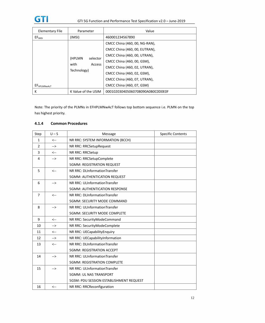
4.1.3 USIM Parameters
Refer to clause 4.5.3 in 3GPP TS 38.508-1 for the default parameters of the test USIM except for the
following parameters
Table 4.2.2-1: USIM Elementary File Parameters
GTI 5G Function and Performance Test Specification v2.0 – June-2019
12
Elementary File Parameter Value
EFIMSI (IMSI) 460001234567890
EFHPLMNwAcT
(HPLMN selector
with Access
Technology)
CMCC China (460, 00, NG-RAN),
CMCC China (460, 00, EUTRAN),
CMCC China (460, 00, UTRAN),
CMCC China (460, 00, GSM),
CMCC China (460, 02, UTRAN),
CMCC China (460, 02, GSM),
CMCC China (460, 07, UTRAN),
CMCC China (460, 07, GSM)
K K Value of the USIM 000102030405060708090A0B0C0D0E0F
Note: The priority of the PLMNs in EFHPLMNwAcT follows top bottom sequence i.e. PLMN on the top
has highest priority.
4.1.4 Common Procedures
Step U – S Message Specific Contents
1 <-- NR RRC: SYSTEM INFORMATION (BCCH)
2 --> NR RRC: RRCSetupRequest
3 <-- NR RRC: RRCSetup
4 --> NR RRC: RRCSetupComplete
5GMM: REGISTRATION REQUEST
5 <-- NR RRC: DLInformationTransfer
5GMM: AUTHENTICATION REQUEST
6 --> NR RRC: ULInformationTransfer
5GMM: AUTHENTICATION RESPONSE
7 <-- NR RRC: DLInformationTransfer
5GMM: SECURITY MODE COMMAND
8 --> NR RRC: ULInformationTransfer
5GMM: SECURITY MODE COMPLETE
9 <-- NR RRC: SecurityModeCommand
10 --> NR RRC: SecurityModeComplete
11 <-- NR RRC: UECapabilityEnquiry
12 --> NR RRC: UECapabilityInformation
13 <-- NR RRC: DLInformationTransfer
5GMM: REGISTRATION ACCEPT
14 --> NR RRC: ULInformationTransfer
5GMM: REGISTRATION COMPLETE
15 --> NR RRC: ULInformationTransfer
5GMM: UL NAS TRANSPORT
5GSM: PDU SESSION ESTABLISHMENT REQUEST
16 <-- NR RRC: RRCReconfiguration

GTI 5G Function and Performance Test Specification v2.0 – June-2019
13
5GMM: DL NAS TRANSPORT
5GSM: PDU SESSION ESTABLISHMENT ACCEPT
17 --> NR RRC: RRCReconfigurationComplete
18 <-- NR RRC: RRCRelease
4.2 Applicability for the UE Configuration
This clause defines the types of test case applicability used in this specification. Each test case shall
clearly state the applicability in the section of “Applicability”
Type Applicability
1 Test cases apply to the devices supporting both SA and NSA
2 Test cases apply to the devices supporting SA Note1
3 Test cases apply to the devices supporting NSA Note2
Note1: Test cases applying to the devices supporting SA also apply to the devices supporting both SA and NSA Note2: Test cases applying to the devices supporting NSA also apply to the devices supporting both SA and NSA
5 Basic Function
5.1 PLMN Selection
5.1.1 PLMN Selection, Multi-RAT Background, Select the highest priority HPLMN,
Automatic Mode
5.1.1.1 Test Purpose
The priority of the PLMNs in USIM HPLMN list is 5G>E-UTRAN. Verify the UE can camp on the
PLMN with highest priority and setup a PS bearer successfully. Verify the UI display is correct. Use the
same PLMN as the real network.
5.1.1.2 Reference specification
3GPP TS 38.304 subclause 5.1
5.1.1.3 Applicability
This test applies to type 1 and 2 devices as described in clause 4.2.
5.1.1.4 Test conditions
[SS configuration]
Cell A, Cell B and Cell C are NR cells. Cell D is an E-UTRAN cell.

GTI 5G Function and Performance Test Specification v2.0 – June-2019
14
NR Cell A
Cell Id=1 TAC = 1
MCC = 460 MNC = 00
Frequency Configuration = f1
NR Cell B
Cell Id=1 TAC = 1
MCC = 460 MNC = 03
Band n78
Frequency Range = 3400MHz-3500MHz
NR Cell C
Cell Id=1 TAC = 1
MCC = 460 MNC = 01
Band n78
Frequency Range = 3500MHz-3600MHz
E-UTRAN Cell D
Cell Id=2 TAC = 2
MCC = 460 MNC = 00
Frequency Configuration = f1
rootSequenceIndex = 0
[UE configuration]
The test USIM shall be inserted.
The UE is in AUTOMATIC network selection mode.
UE works in SA mode.
[Initial conditions]
SS
NR Cell A, Cell B and Cell C are not active.
E-UTRAN Cell D is not active.
The test shall be performed under ideal radio conditions.
UE
UE is powered off
5.1.1.5 Test procedure
Table 5.1.1.5-1: Time of cell power level and parameter changes
Time Parameter Unit NR Cell A NR Cell B NR Cell C E-UTRAN
Cell D
Remark
T0 SS/PBCH, SSS EPRE dBm/SCS -125 -125 -125 /

GTI 5G Function and Performance Test Specification v2.0 – June-2019
15
Reference Signal EPRE dBm/15kHz / / / -125
T1 SS/PBCH, SSS EPRE dBm/SCS -85 -85 -85 /
Reference Signal EPRE dBm/15kHz / / / -85
T2 SS/PBCH, SSS EPRE dBm/SCS Not Active -85 -85 /
Reference Signal EPRE dBm/15kHz / / / -85
PREAMBLE
1. Activate NR Cell A, NR Cell B , NR Cell C and E-UTRAN Cell D. The SS configures the
transmission of the Master Information Block and starts the System Information Block
broadcasting on all cells.
2. The SS configures the initial power according to T0 in Table 5.1.1.5-1.
3. The UE is powered ON.
MAIN BODY
4. The SS increases the TX power of Cells according to T1 in Table 5.1.1.5-1.
5. The UE performs Registration procedure on NR Cell A according to subclause 5.4.1 step3-18.
SS releases the RRC connection. The UE transits to Idle state.
6. The tag on the UI indicate that UE has registered on NR network.
7. Deactivate NR Cell A. (Refer Table 5.1.1.5 -1: Time T2). NR Cell B and Cell C remains exist.
8. The UE performs TAU procedure on E-UTRAN Cell D. SS releases the RRC connection. The UE
transits to Idle state
9. The tag on the UI indicate that UE has registered on LTE network.
POSTAMBLE
10. The UE is powered OFF
11. The UE performs MO Detach procedure on E-UTRAN Cell D.
12. Deactivate NR Cell B, NR Cell C and E-UTRAN Cell D.
Table 5.1.1.5-2: Message Sequence
Step Message Sequence Verdict
U-S Layer Message Specific Contents
1 RRC Activate NR Cell A, NR Cell B , NR Cell C and E-UTRAN Cell D
2 Configure the initial power according to T0 in Table 5.1.1.5-1.
3 UE Switch On UE AT Command
4 Increases the TX power of Cells according to T1 in Table 5.1.1.5-1
5
RRC NAS
UE performs Registration procedure on NR Cell A according to subclause 5.4.1 step3-18.
PASS
6 UE
The tag on the UI indicate that UE has registered on NR network.
7 Deactivate NR Cell A. (Refer Table 5.1.1.5 -2: Time T2). NR Cell B and Cell C remains exist.
8
RRC NAS
UE performs TAU procedure on E-UTRAN Cell D PASS

GTI 5G Function and Performance Test Specification v2.0 – June-2019
16
9 UE
The tag on the UI indicate that UE has registered on LTE network.
10 UE Switch Off UE AT Command
1
1
RRC NAS
UE performs MO Detach procedure on E-UTRAN Cell D
12 Deactivate NR Cell B, NR Cell C and E-UTRAN Cell D.
5.1.1.6 Expected Result
Step 5, UE could camps on NR Cell A
Step 8, UE could camps on E-UTRAN Cell D
5.2 Cell Selection
5.2.1 Multi-mode Environment Cell Selection, NR Cell Available
5.2.1.1 Test Purpose
Verify that the UE will correctly select and camp on NR cell basend on the cell selection priority
(NR > LTE).
5.2.1.2 Reference specification
3GPP TS 38.304, clause 5.2.3.
5.2.1.3 Applicability
This test applies to Type 1 and 2 devices as described in clause 4.2.
5.2.1.4 Test conditions
[SS configuration]
Cell A is a E-UTRAN cell.
Cell B is a NR Cell.
E-UTRAN Cell A
Cell Id=01 TAC = 01
MCC-MNC = 460-00
E-UTRA Band = 41
EARFCN= f1
rootSequenceIndex TDD = 0
Reference Signal EPRE= -91dBm/15kHz
upperLayerIndication-r15=true
NR Cell B
Cell Id=02 TAC = 01

GTI 5G Function and Performance Test Specification v2.0 – June-2019
17
MCC = 460 MNC = 00
NR Band = n41
NR-ARFCN= f1
SS/PBCH SSS EPRE = -90 dBm/30kHz
[UE configuration]
The test UICC with USIM should be inserted
The UE is in AUTOMATIC network selection mode.
UE works in SA mode.
[Initial conditions]
SS
E-UTRAN Cell A is not active
NR Cell B is not active
The test shall be performed under ideal radio conditions.
UE
UE is powered off
5.2.1.5 Test procedure
Table 5.2.1.5-0: Time instances of cell power level and parameter changes
Parameter Unit E-UTRAN Cell A NR Cell B
T0 SS/PBCH
SSS EPRE dBm/SCS -85 -90
PREAMBLE
1. Activate E-UTRAN Cell A and NR Cell B. The SS configures the corresponding Master
Information Block and System Information Block broadcast.
2. The SS configures the initial power according to T0 in Table 5.2.1.5-0.
3. The UE is powered ON.
MAIN BODY
4. The UE performs the registration procedure on Cell B (see 38.508, Table 4.5.2.2 ).
POSTAMBLE
5. The UE is powered OFF.
6. Deactivate E-UTRAN Cell A and NR Cell B.
Table 5.2.1.5-1: Message Sequence
Step Message Sequence Verdict
U-S Layer Message Specific Contents
1 RRC SS Activates E-UTRAN Cell A and Cell B
2 The SS configures the initial power
according to T0 in Table 5.2.1.5-1
3 UE Switch On UE AT Command

GTI 5G Function and Performance Test Specification v2.0 – June-2019
18
4
NAS
RRC
The UE performs the registration procedure
on Cell B (see 38.508, Table 4.5.2.2 )
PASS
5 UE Switch Off UE AT Command
6 Deactivate E-UTRAN Cell A and NR Cell B.
5.2.1.6 Expected Result
Step 4, UE could select NR Cell B and camps on the NR Cell B
5.2.2 Multi-mode Environment Cell Selection, E-UTRAN Available
5.2.2.1 Test Purpose
Verify that the UE will correctly select and camp on E-UTRAN cell when E-UTRAN cell available
but no NR cell available.
5.2.2.2 Reference specification
3GPP TS 36.304, clause 5.2.3.
5.2.2.3 Applicability
This test applies to Type 1 and 2 devices as described in clause 4.2.
5.2.2.4 Test conditions
[SS configuration]
Cell A is a TD-LTE cell.
E-UTRAN Cell A
Cell Id=01 TAC = 01
MCC-MNC = 460-00
E-UTRA Band = 41
EARFCN= f1
rootSequenceIndex TDD = 0
Reference Signal EPRE= -85dBm/15kHz
upperLayerIndication-r15=true
[UE configuration]
The test UICC with USIM should be inserted
The UE is in AUTOMATIC network selection mode.
UE works in 4G mode.
[Initial conditions]
SS
E-UTRAN Cell A is not active

GTI 5G Function and Performance Test Specification v2.0 – June-2019
19
The test shall be performed under ideal radio conditions.
UE
UE is powered off
5.2.2.5 Test procedure
Table 5.2.2.5-1: Time instances of cell power level and parameter changes
Parameter Unit E-UTRAN Cell A
T0 SS/PBCH
SSS EPRE dBm/SCS -85
PREAMBLE
1. Activate E-UTRAN Cell A. The SS configures the corresponding Master Information Block and
System Information Block broadcast.
2. The SS configures the initial power according to T0 in Table 5.2.2.5-1.
3. The UE is powered ON.
MAIN BODY
4. The UE performs the registration procedure with activation of the initial default EPS bearer
on Cell A (see 36.508, 4.5.2 ).
POSTAMBLE
5. The UE is powered OFF.
6. Deactivate E-UTRAN Cell A.
Table 5.2.1.5-1: Message Sequence
Step Message Sequence Verdict
U-S Layer Message Specific Contents
1 RRC SS Activates E-UTRAN Cell A
2 The SS configures the initial power
according to T0 in Table 5.2.2.5-1.
2 UE Switch On UE AT Command
3
NAS
RRC
The UE performs the registration procedure
with activation of the initial default EPS
bearer on Cell A (see 36.508, 4.5.2 ).
PASS
4 UE Switch Off UE AT Command
5 Deactivate E-UTRAN Cell A.
5.2.2.6 Expected Result
Step 3, UE could select the E-UTRA cell A and camp on the E-UTRA cell A
5.2.3. Multi-mode Environment Cell Selection, NR Cell Available
5.2.3.1. Test Purpose

GTI 5G Function and Performance Test Specification v2.0 – June-2019
20
When SA NR cell and NSA PS-Cell(NR) available,UE could camps on the NR cell
5.2.3.2. Reference specification
3GPP TS 38.304, clause 5.2.3.
5.2.3.3. Applicability
This test applies to type 1 and 2 devices as described in clause 4.2.
5.2.3.4. Test conditions
[SS configuration]
Cell A is a NR cell.
Cell B is a NR Cell.
Cell B supports NSA
NR Cell A
Cell Id=01 TAC = 01
MCC = 460 MNC = 00
NR-ARFCN= f1
SS/PBCH SSS EPRE = -85 dBm/30kHz
NR Cell B
Cell Id=02 TAC = 01
MCC = 460 MNC = 00
NR-ARFCN= f1
SS/PBCH SSS EPRE = -85 dBm/30kHz
[UE configuration]
The test UICC with USIM should be inserted
The UE is in AUTOMATIC network selection mode.
UE works in SA mode.
[Initial conditions]
SS
NR Cell A is not active
NR Cell B is not active
The test shall be performed under ideal radio conditions.
UE
UE is powered off
5.2.3.5. Test procedure
Table 5.1.1.5-1: Time of cell power level and parameter changes

GTI 5G Function and Performance Test Specification v2.0 – June-2019
21
Time Parameter NR Cell A NR Cell B
T0 SS/PBCH
SSS EPRE
-85 -85
PREAMBLE
1. Activate NR Cell A and Cell B. The SS configures the corresponding Master Information Block
and System Information Block broadcast.
2. The SS configures the initial power according to T0 in Table 5.2.3.5-1.
3. The UE is powered ON.
MAIN BODY
4. The UE performs the registration procedure on Cell A (see 38.508, Table 4.5.2.2 ).
POSTAMBLE
5. The UE is powered OFF.
6. Deactivate NR Cell A and NR Cell B.
Table 5.2.3.5-1: Message Sequence
Step Message Sequence Verdict
U-S Layer Message Specific Contents
1 RRC SS Activates NR Cell A and Cell B
2 The SS configures the initial power according
to T0 in Table 5.2.3.5-1.
3 UE Switch On UE AT Command
4
NAS
RRC
The UE performs the registration procedure
on Cell A (see 38.508, Table 4.5.2.2 ).
PASS
5 UE Switch Off UE AT Command
6 Deactivate NR Cell A and NR Cell B.
5.2.3.6. Expected Result
Step 4 UE selects the NR Cell A and camps on the Cell A.
5.2.4. Multi-mode Environment Cell Selection, NSA Cell Available
5.2.4.1. Test Purpose
Verify that the UE will correctly select and camp on NSA E-UTRAN cell when NSA E-UTRAN cell
available and no NR cell
5.2.4.2. Reference specification
3GPP TS 36.304, clause 5.2.3.

GTI 5G Function and Performance Test Specification v2.0 – June-2019
22
5.2.4.3. Applicability
This test applies to type 1 devices as described in clause 4.2.
5.2.4.4. Test conditions
[SS configuration]
Cell A is a TD-LTE cell.
Cell B is a NR Cell.
Cell A supports NSA.
E-UTRAN Cell A
Cell Id=01 TAC = 01
MCC-MNC = 460-00
E-UTRA Band = 41
EARFCN= f1
Bandwidth = 20 MHz
rootSequenceIndex TDD = 0
Reference Signal EPRE= -85dBm/15kHz
upperLayerIndication-r15=true
NR Cell B
Cell Id=02 TAC = 01
MCC = 460 MNC = 00
NR-ARFCN= f1
Bandwidth = 100 MHz
SS/PBCH SSS EPRE = -85 dBm/30kHz
[UE configuration]
The test UICC with USIM should be inserted
The UE is in AUTOMATIC network selection mode.
UE works in NSA mode.
[Initial conditions]
SS
E-UTRAN Cell A is not active
NR Cell B is not active
The test shall be performed under ideal radio conditions.
NR Cell B is barred with cellBarred IE in MIB
UE
UE is powered off

GTI 5G Function and Performance Test Specification v2.0 – June-2019
23
5.2.4.5. Test procedure
Table 5.1.1.5-1: Time of cell power level and parameter changes
Time Parameter E-UTRAN Cell A NR Cell B
T0 SS/PBCH
SSS EPRE
-85 -85
PREAMBLE
1. Activate E-UTRAN Cell A and Cell B. The SS configures the corresponding Master Information
Block and System Information Block broadcast.
2. The SS configures the initial power according to T0 in Table 5.2.4.5-1.
3. The UE is powered ON.
MAIN BODY
4. The UE performs the registration procedure with activation of the initial default EPS bearer
on Cell A (see 36.508, 4.5.2 ).
POSTAMBLE
5. The UE is powered OFF.
6. Deactivate E-UTRAN Cell A and NR Cell B.
Table 5.2.4.5-1: Message Sequence
Step Message Sequence Verdict
U-S Layer Message Specific Contents
1 RRC SS Activates E-UTRAN Cell A and Cell B
2 The SS configures the initial power according
to T0 in Table 5.2.4.5-1
3 UE Switch On UE AT Command
4
NAS
RRC
The UE performs the registration procedure
with activation of the initial default EPS
bearer on Cell A (see 36.508, 4.5.2 ).
PASS
5 UE Switch Off UE AT Command
6 Deactivate E-UTRAN Cell A and NR Cell B.
5.2.4.6. Expected Result
Step 4 UE selects the E-UTRAN Cell A and camps on the Cell A.
5.2.5 Initial Cell Selection from Power-Up
5.2.5.1 Test Purpose

GTI 5G Function and Performance Test Specification v2.0 – June-2019
24
Verify that the UE will correctly select and camp on the right NR cell based on channel quality
from power-up when inter-frequency cells with different bandwidth and inter-band cell existing
simultaneously.
5.2.5.2 Reference specification
3GPP TS 38.304, clause 5.2.3.
5.2.5.3 Applicability
This test applies to type 1 and 2 devices as described in clause 4.2.
5.2.5.4 Test conditions
[SS configuration]
Cell A is a NR Serving Cell, Cell B and Cell C are inter-frequency cell and Cell D is inter-band cell.
NR Cell A
Cell Id=01 TAC = 01
MCC = 460 MNC = 00
Band=n41
NR-ARFCN= f4
NR Cell B
Cell Id=02 TAC = 01
MCC = 460 MNC = 00
Band=n41
NR-ARFCN= f3
NR Cell C
Cell Id=03 TAC = 01
MCC = 460 MNC = 00
Band=n41
NR-ARFCN= f2
NR Cell D
Cell Id=04 TAC = 01
MCC = 460 MNC = 00
Band=n79
NR-ARFCN= f1
[UE configuration]
The test UICC with USIM should be inserted
The UE is in AUTOMATIC network selection mode.
UE works in SA mode.

GTI 5G Function and Performance Test Specification v2.0 – June-2019
25
[Initial conditions]
SS
NR Cell A is not active
The test shall be performed under ideal radio conditions.
UE
UE is powered off
5.2.5.5 Test procedure
Table 5.2.5.5-0: Time instances of cell power level and parameter changes
Parameter Unit Cell A Cell B Cell C Cell D
T0
SS/PBCH
SSS EPRE dBm/SCS
-88 -94 -94 -94
T1 -94 -88 -94 -94
T2 -94 -94 -88 -94
T3 -94 -94 -88 -94
PREAMBLE
1. Activate NR CellA,NR CellB,NR CellC,NR CellD. The SS configures the corresponding Master
Information Block and System Information Block broadcast.
2. The SS configures the initial power according to T0 in Table 5.2.5.5-0.
MAIN BODY
3. The UE is powered ON.
4. The UE performs the registration procedure on Cell A (see 38.508, Table 4.5.2.2 ).
5. The UE is powered OFF.
6. The SS configures the initial power according to T1 in Table 5.2.5.5-0.
7. The UE is powered ON.
8. The UE performs the registration procedure on Cell B (see 38.508, Table 4.5.2.2 ).
9. The UE is powered OFF.
10. The SS configures the initial power according to T2 in Table 5.2.5.5-0.
11. The UE is powered ON.
12. The UE performs the registration procedure on Cell C (see 38.508, Table 4.5.2.2 ).
13. The UE is powered OFF.
14. The SS configures the initial power according to T2 in Table 5.2.5.5-0.
15. The UE is powered ON.
16. The UE performs the registration procedure on Cell D (see 38.508, Table 4.5.2.2 ).
POSTAMBLE
17. The UE is powered OFF.
18. Deactivate NR CellA,NR CellB,NR CellC,NR CellD.
Table 5.2.5.5-1: Message Sequence
Step Message Sequence Verdict
U-S Layer Message Specific Contents

GTI 5G Function and Performance Test Specification v2.0 – June-2019
26
1 RRC Activate NR Cell A,NR Cell B,NR Cell C,NR Cell D
2 SS The SS configures the initial power according to
T0 in Table 5.2.5.5-0.
3 UE Switch On UE AT Command
4
NAS
RRC
The UE performs the registration procedure on
Cell A (see 38.508, Table 4.5.2.2 )
PASS
5 UE Switch Off UE AT Command
6 SS The SS configures the initial power according to
T1 in Table 5.2.5.5-0.
7 UE Switch On UE AT Command
8
NAS
RRC
The UE performs the registration procedure on
Cell B (see 38.508, Table 4.5.2.2 )
PASS
10 SS The SS configures the initial power according to T2 in
Table 5.2.5.5-0.
11 UE Switch On UE AT Command
12
NAS
RRC
The UE performs the registration procedure on
Cell C (see 38.508, Table 4.5.2.2 )
PASS
13 UE Switch Off UE AT Command
14 SS The SS configures the initial power according to T2 in
Table 5.2.5.5-0.
15 UE Switch On UE AT Command
16
NAS
RRC
The UE performs the registration procedure on
Cell D (see 38.508, Table 4.5.2.2 )
PASS
17 UE Switch Off UE AT Command
18 Deactivate NR CellA,NR CellB,NR CellC,NR CellD.
5.2.5.6 Expected Result
Step 4, UE could select NR Cell A and camp on the NR Cell A
Step 8, UE could select NR Cell C and camps on the NR Cell B
Step 12, UE could select NR Cell A and camp on the NR Cell C
Step 16, UE could select NR Cell C and camps on the NR Cell D
5.3 RRC connection/connection reconfiguration
5.3.1 RRC connection re-establishment, radio link failure, re-establish to a Prepared
Inter-Freq cell
5.3.1.1 Test Purpose
When UE in RRC_CONNECTED state, verify that UE could re-establish the RRC connection on the
prepared Inter-Freq cell.
5.3.1.2 Reference specification

GTI 5G Function and Performance Test Specification v2.0 – June-2019
27
3GPP TS 38.331 clauses 5.3.7, 5.3.10
3GPP TS 38.304 clause 5.2.3
5.3.1.3 Applicability
This test applies to Type 1 and 2 devices as described in clause 4.2
5.3.1.4 Test conditions
[SS configuration]
Cell A is a NR cell.
Cell B is a NR Cell.
NR Cell A
Cell Id=01 TAC = 01
MCC = 460 MNC = 00
NR-ARFCN= f1
SS/PBCH SSS EPRE = -85 dBm/30kHz
NR Cell B
Cell Id=02 TAC = 01
MCC = 460 MNC = 00
NR-ARFCN= f1
SS/PBCH SSS EPRE = -125 dBm/30kHz
[UE configuration]
The test UICC with USIM should be inserted
The UE is in AUTOMATIC network selection mode.
UE works in SA mode.
[Initial conditions]
SS
NR Cell A is not active
NR Cell B is not active
The test shall be performed under ideal radio conditions.
UE
UE is powered off
5.3.1.5 Test procedure
Table 5.3.1.5-0: Time instances of cell power level and parameter changes
Parameter Unit Cell A Cell B
T0 SS/PBCH
SSS EPRE dBm/SCS -88 Not Active
T1 SS/PBCH
SSS EPRE dBm/SCS Not Active -88
GTI 5G Function and Performance Test Specification v2.0 – June-2019
28
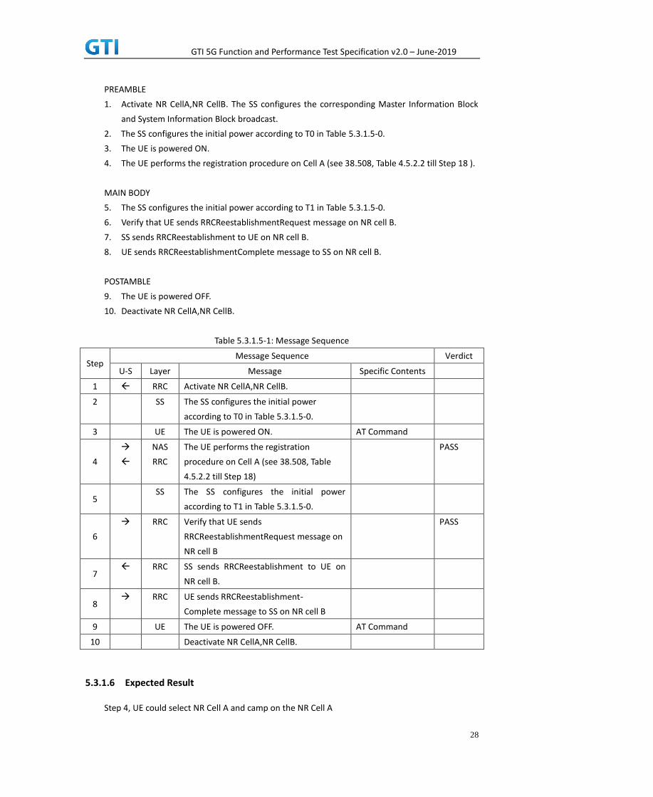
PREAMBLE
1. Activate NR CellA,NR CellB. The SS configures the corresponding Master Information Block
and System Information Block broadcast.
2. The SS configures the initial power according to T0 in Table 5.3.1.5-0.
3. The UE is powered ON.
4. The UE performs the registration procedure on Cell A (see 38.508, Table 4.5.2.2 till Step 18 ).
MAIN BODY
5. The SS configures the initial power according to T1 in Table 5.3.1.5-0.
6. Verify that UE sends RRCReestablishmentRequest message on NR cell B.
7. SS sends RRCReestablishment to UE on NR cell B.
8. UE sends RRCReestablishmentComplete message to SS on NR cell B.
POSTAMBLE
9. The UE is powered OFF.
10. Deactivate NR CellA,NR CellB.
Table 5.3.1.5-1: Message Sequence
Step Message Sequence Verdict
U-S Layer Message Specific Contents
1 RRC Activate NR CellA,NR CellB.
2 SS The SS configures the initial power
according to T0 in Table 5.3.1.5-0.
3 UE The UE is powered ON. AT Command
4
NAS
RRC
The UE performs the registration
procedure on Cell A (see 38.508, Table
4.5.2.2 till Step 18)
PASS
5 SS The SS configures the initial power
according to T1 in Table 5.3.1.5-0.
6
RRC Verify that UE sends
RRCReestablishmentRequest message on
NR cell B
PASS
7 RRC SS sends RRCReestablishment to UE on
NR cell B.
8 RRC UE sends RRCReestablishment-
Complete message to SS on NR cell B
9 UE The UE is powered OFF. AT Command
10 Deactivate NR CellA,NR CellB.
5.3.1.6 Expected Result
Step 4, UE could select NR Cell A and camp on the NR Cell A

GTI 5G Function and Performance Test Specification v2.0 – June-2019
29
Step 6, UE sends RRCReestablishmentRequest message on NR cell B
5.3.2 BWP configuration, downlink and uplink BWP addition /release
5.3.2.1 Test Purpose
When UE in RRC_CONNECTED state, verify that UE could add and release downlink and uplink
BWP correctly.
5.3.2.2 Reference specification
3GPP TS 38.331 clause 5.3.5.
5.3.2.3 Applicability
This test applies to the device that supports SA or SA+NSA
5.3.2.4 Test conditions
[SS configuration]
Cell A is a NR cell.
NR Cell A
Cell Id=01 TAC = 01
MCC = 460 MNC = 00
NR-ARFCN= f1
SS/PBCH SSS EPRE = -85 dBm/30kHz
[UE configuration]
The test UICC with USIM should be inserted
The UE is in AUTOMATIC network selection mode.
UE works in SA mode.
[Initial conditions]
SS
NR Cell A is not active
The test shall be performed under ideal radio conditions.
UE
UE is powered off
5.3.2.5 Test procedure
Table 5.3.2.5-0: Time instances of cell power level and parameter changes
Parameter Unit Cell A
T0 SS/PBCH
SSS EPRE dBm/SCS -85

GTI 5G Function and Performance Test Specification v2.0 – June-2019
30
PREAMBLE
1. Activate NR CellA The SS configures the corresponding Master Information Block and System
Information Block broadcast.
2. The SS configures the initial power according to T0 in Table 5.3.2.5-0.
3. The UE is powered ON.
4. The UE performs the registration procedure on Cell A (see 38.508, Table 4.5.2.2 till Step 18 ).
MAIN BODY
5. SS sends RRCReconfiguration to UE on NR cell A.
6. Verify that UE sends RRCReconfigurationComplete message to SS on NR cell A.
POSTAMBLE
7. The UE is powered OFF.
8. Deactivate NR CellA.
Table 5.3.2.5-1: Message Sequence
Step Message Sequence Verdict
U-S Layer Message Specific Contents
1 RRC Activate NR CellA
2 The SS configures the initial power according to
T0 in Table 5.3.2.5-0
3 UE The UE is powered ON. AT Command
4
NAS
RRC
The UE performs the registration procedure on
Cell A (see 38.508, Table 4.5.2.2 till Step 18)
PASS
5 SS sends RRCReconfiguration to UE on NR cell
A.
6
Verify that UE sends
RRCReconfigurationComplete message to SS on
NR cell A.
PASS
7 UE The UE is powered OFF. AT Command
8 Deactivate NR CellA.
5.3.2.6 Expected Result
Step 4, UE could select NR Cell A and camp on the NR Cell A
Step 6, UE sends RRCReconfigurationComplete message on NR cell A.
5.4 Registration/De-registration
5.4.1 Initial Registration, SA
5.4.1.1 Test Purpose
Verify the UE can register on NR Cell successfully.

GTI 5G Function and Performance Test Specification v2.0 – June-2019
31
5.4.1.2 Reference specification
3GPP TS 24.501, clause 5.5
3GPP TS 24.501, clause 6.4
5.4.1.3 Applicability
This test applies to type 1 and 2 devices as described in clause 4.2.
5.4.1.4 Test conditions
[SS configuration]
Cell A is a NR cell.
NR Cell A
Cell Id=1 TAC = 1
MCC = 460 MNC = 00
NR-ARFCN= f1
SS/PBCH SSS EPRE = -85 dBm/30kHz
[UE configuration]
The test UICC with USIM should be inserted.
The UE is in AUTOMATIC network selection mode.
UE works in SA mode.
[Initial conditions]
SS
NR Cell A is not active
The test shall be performed under ideal radio conditions.
UE
UE is powered off
5.4.1.5 Test procedure
PREAMBLE
1. Activate NR Cell A.The SS configures the corresponding Master Information Block and System
Information Block broadcast.
2. The UE is powered ON.
MAIN BODY
3. The UE sends an RRCConnectionRequest message.
4. The SS sends an RRCConnectionSetup message.
5. The UE sends an RRCConnectionSetupComplete message including the REGISTRATION
REQUEST message to initiate the the registration procedure.
6. The SS sends an AUTHENTICATION REQUEST message to initiate the 5G AKA based primary
authentication and key agreement procedure.

GTI 5G Function and Performance Test Specification v2.0 – June-2019
32
7. The UE sends the AUTHENTICATION RESPONSE message.
8. The SS sends a NAS SECURITY MODE COMMAND message to activate NAS security.
9. The UE sends a NAS SECURITY MODE COMPLETE message
10. The SS sends a SecurityModeCommand message to activate AS security.
11. The UE sends a SecurityModeComplete message and establishes the initial security
configuration.
12. The SS sends a UECapabilityEnquiry message to initiate the UE radio access capability transfer
procedure.
13. The UE sends a UECapabilityInformation message to transfer UE radio access capability.
14. The SS sends an REGISTRATION ACCEPT message.
15. The UE sends an REGISTRATION COMPLETE message.
16. The UE sends an PDU SESSION ESTABLISHMENT REQUEST message, verify that PDU session
type is IPv4v6.
17. The SS sends an RRCConnectionReconfiguration message to establish the default bearer, and
PDU SESSION ESTABLISHMENT ACCEPT is piggybacked.
18. The UE sends an RRCConnectionReconfigurationComplete message
POSTAMBLE
19. The UE is powered off
20. The UE sends a DEREGISTRATION REQUEST message.
21. The SS initiates a RRC release procedure.
22. Deactivate NR Cell A.
Table 5.1.1.55.4.1.5-1: Message Sequence
Step Message Sequence Verdict
U-S Layer Message Specific Contents
1 RRC Activates E-UTRAN Cell A
2 UE Switch On UE AT Command
3 RRC NR RRC: RRCSetupRequest
4 RRC NR RRC: RRCSetup
5 RRC
NAS
NR RRC: RRCSetupComplete
5GMM: REGISTRATION REQUEST
PASS
6 RRC
NAS
NR RRC: DLInformationTransfer
5GMM: AUTHENTICATION REQUEST
7 RRC
NAS
NR RRC: ULInformationTransfer
5GMM: AUTHENTICATION RESPONSE
PASS
8 RRC
NAS
NR RRC: DLInformationTransfer
5GMM: SECURITY MODE COMMAND
9 RRC
NAS
NR RRC: ULInformationTransfer
5GMM: SECURITY MODE COMPLETE
PASS
10 RRC NR RRC: SecurityModeCommand
11 RRC NR RRC: SecurityModeComplete PASS
12 RRC NR RRC: UECapabilityEnquiry
13 RRC NR RRC: UECapabilityInformation PASS

GTI 5G Function and Performance Test Specification v2.0 – June-2019
33
14 RRC
NAS
NR RRC: DLInformationTransfer
5GMM: REGISTRATION ACCEPT
15 RRC
NAS
NR RRC: ULInformationTransfer
5GMM: REGISTRATION COMPLETE
PASS
16 RRC
NAS
NR RRC: ULInformationTransfer
5GMM: UL NAS TRANSPORT
5GSM: PDU SESSION ESTABLISHMENT
REQUEST, verify that PDU session type is
IPv4v6.
PASS
17 RRC
NAS
NR RRC: RRCReconfiguration
5GMM: DL NAS TRANSPORT
5GSM: PDU SESSION ESTABLISHMENT
ACCEPT
18 RRC NR RRC: RRCReconfigurationComplete PASS
19 UE Switch Off UE, AT Command
20 NAS UE sends a DEREGISTRATION REQUEST
message.
PASS
21 RRC SS initiates a RRC release procedure.
22 Deactivate NR Cell A
5.4.1.6 Expected Result
Verify the UE can register on NR Cell successfully.
5.5 NSA
5.5.1 Multi-mode Environment Cell selection for NSA
5.5.1.1 Test Purpose
Verify that the UE will correctly select and camp on a LTE cell based on channel quality from
power-up when LTE and NSA NR cell both exist.
5.5.1.2 Reference specification
3GPP TS 36.304, clause 5.2.3.
5.5.1.3 Applicability
This test applies to Type 1 and Type 3 devices as described in clause 4.2.
5.5.1.4 Test conditions
[SS configuration]
Cell A is a E-UTRAN cell and also NSA MCG. Cell B and Cell C are 4G only cell
Cell D is a NR Cell (NSA SCG, not SA NR cell).

GTI 5G Function and Performance Test Specification v2.0 – June-2019
34
E-UTRAN Cell A
Cell Id=01 TAC = 01
MCC-MNC = 460-00
EARFCN= f1
rootSequenceIndex = 0
Reference Signal EPRE= -85 dBm/15kHz
upperLayerIndication-r15=true
E-UTRAN Cell B
Cell Id=02 TAC = 02
MCC-MNC = 460-00
Band = B41
EARFCN= f2
rootSequenceIndex = 0
Reference Signal EPRE= -94 dBm/15kHz
upperLayerIndication-r15=false
E-UTRAN Cell C
Cell Id=03 TAC = 03
MCC-MNC = 460-00
Band = B41
EARFCN= f3
rootSequenceIndex = 0
Reference Signal EPRE= -94 dBm/15kHz
upperLayerIndication-r15=false
NR Cell D
Cell Id=01 TAC = 01
MCC = 460 MNC = 00
NR-ARFCN= f1
SS/PBCH SSS EPRE = -94 dBm/30kHz
[UE configuration]
The test UICC with USIM should be inserted
The UE is in AUTOMATIC network selection mode.
UE works in NSA mode.
[Initial conditions]
SS
E-UTRAN Cell A is not active
NR Cell B is not active
The test shall be performed under ideal radio conditions.
UE

GTI 5G Function and Performance Test Specification v2.0 – June-2019
35
UE is powered off
5.5.1.5 Test procedure
Table 5.5.1.5-0: Time instances of cell power level and parameter changes
Parameter Unit Cell A Cell B Cell C Cell D
T0 SS/PBCH, SSS EPRE dBm/SCS / / / -88
Reference Signal EPRE dBm/15kHz -88 -94 -94 /
T1 SS/PBCH, SSS EPRE dBm/SCS / / -88 -88
Reference Signal EPRE dBm/15kHz -94 -88 -94 /
T2 SS/PBCH, SSS EPRE dBm/SCS / / -88 -88
Reference Signal EPRE dBm/15kHz -94 -94 -88 /
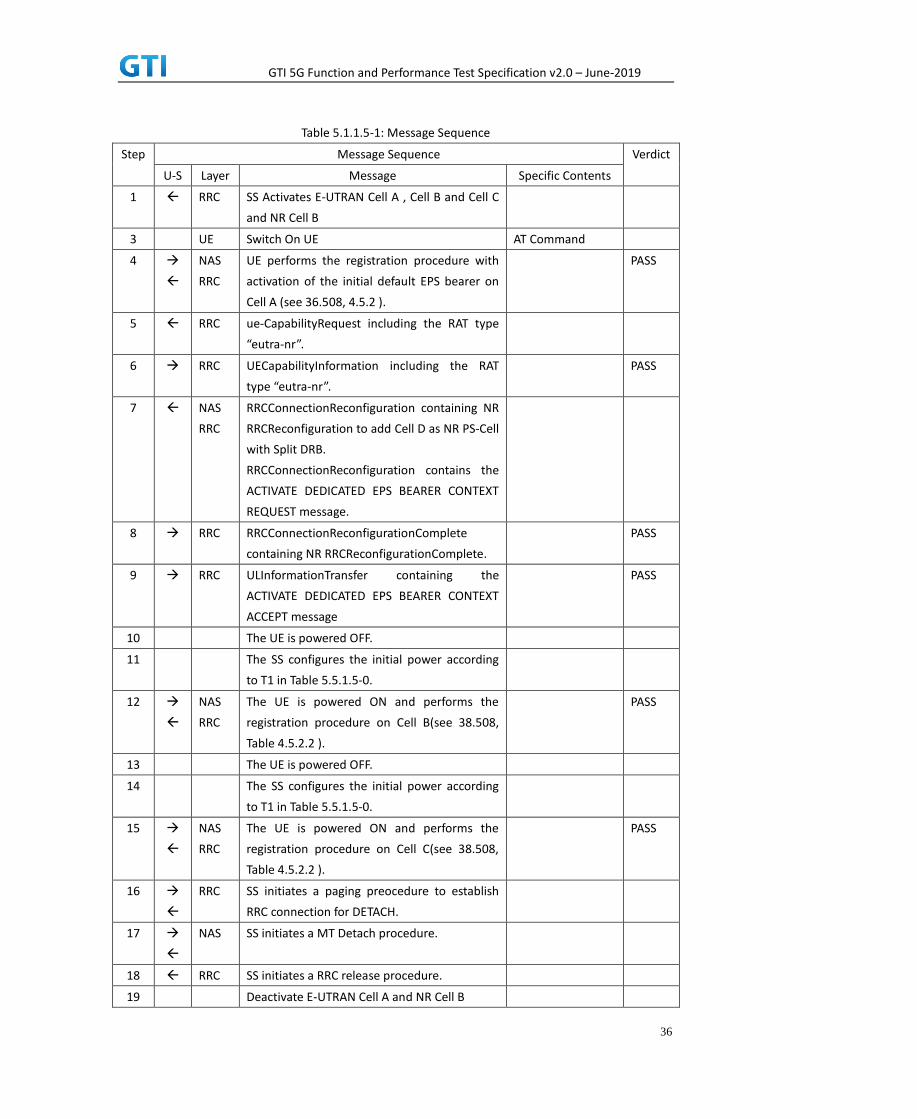
PREAMBLE
1. Activate E-UTRAN Cell A, Cell B, Cell C and NR Cell D. The SS configures the corresponding
Master Information Block and System Information Block broadcast.
2. The SS configures the initial power according to T0 in Table 5.5.1.5-0 .
3. The UE is powered ON.
MAIN BODY
4. The UE performs the registration procedure with activation of the initial default EPS bearer
on Cell A (see 36.508, 4.5.2 ).
5. The SS sends an ue-CapabilityRequest including the RAT type “eutra-nr”.
6. Verify the UE sends UECapabilityInformation message including the RAT type “eutra-nr”.
7. The SS sends an RRCConnectionReconfiguration message containing NR RRCReconfiguration
message to add Cell D as NR PS-Cell with Split DRB. RRCConnectionReconfiguration message
contains the ACTIVATE DEDICATED EPS BEARER CONTEXT REQUEST message.
8. The UE sends an RRCConnectionReconfigurationComplete message containing NR
RRCReconfigurationComplete message.
9. The UE sends an ULInformationTransfer message containing the ACTIVATE DEDICATED EPS
BEARER CONTEXT ACCEPT message.The RRC connection is released by the SS.
10. The UE is powered OFF.
11. The SS configures the initial power according to T1 in Table 5.5.1.5-0.
12. The UE is powered ON. Verify that the UE performs the registration procedure on Cell B(see
38.508, Table 4.5.2.2 ).
13. The UE is powered OFF.
14. The SS configures the initial power according to T2 in Table 5.5.1.5-0.
15. The UE is powered ON. Verify that the UE performs the registration procedure on Cell C(see
38.508, Table 4.5.2.2 ).
POSTAMBLE
16. The SS initiates a paging preocedure to establish RRC connection for DETACH.
17. The SS initiates a MT Detach procedure.
18. The SS initiates a RRC release procedure.
19. Deactivate E-UTRAN Cell A , Cell B, Cell C and NR Cell D.
GTI 5G Function and Performance Test Specification v2.0 – June-2019
36
Table 5.1.1.5-1: Message Sequence
Step Message Sequence Verdict
U-S Layer Message Specific Contents
1 RRC SS Activates E-UTRAN Cell A , Cell B and Cell C
and NR Cell B
3 UE Switch On UE AT Command
4
NAS
RRC
UE performs the registration procedure with
activation of the initial default EPS bearer on
Cell A (see 36.508, 4.5.2 ).
PASS
5 RRC ue-CapabilityRequest including the RAT type
“eutra-nr”.
6 RRC UECapabilityInformation including the RAT
type “eutra-nr”.
PASS
7 NAS
RRC
RRCConnectionReconfiguration containing NR
RRCReconfiguration to add Cell D as NR PS-Cell
with Split DRB.
RRCConnectionReconfiguration contains the
ACTIVATE DEDICATED EPS BEARER CONTEXT
REQUEST message.
8 RRC RRCConnectionReconfigurationComplete
containing NR RRCReconfigurationComplete.
PASS
9 RRC ULInformationTransfer containing the
ACTIVATE DEDICATED EPS BEARER CONTEXT
ACCEPT message
PASS
10 The UE is powered OFF.
11 The SS configures the initial power according
to T1 in Table 5.5.1.5-0.
12
NAS
RRC
The UE is powered ON and performs the
registration procedure on Cell B(see 38.508,
Table 4.5.2.2 ).
PASS
13 The UE is powered OFF.
14 The SS configures the initial power according
to T1 in Table 5.5.1.5-0.
15
NAS
RRC
The UE is powered ON and performs the
registration procedure on Cell C(see 38.508,
Table 4.5.2.2 ).
PASS
16
RRC SS initiates a paging preocedure to establish
RRC connection for DETACH.
17
NAS SS initiates a MT Detach procedure.
18 RRC SS initiates a RRC release procedure.
19 Deactivate E-UTRAN Cell A and NR Cell B
GTI 5G Function and Performance Test Specification v2.0 – June-2019
37
5.5.1.6 Expected Result
Step 4, UE could correctly select and camp on the E-UTRAN cell A
Step 6, UE could correctly report its EN-DC capability
Step 8 and 9, UE could support the establishment of NSA SCG.
Step 12, UE could correctly select and camp on the E-UTRAN cell B
Step 15, UE could correctly select and camp on the E-UTRAN cell C
5.5.2 Initial Registration, NSA
5.5.2.1 Test Purpose
Verify the UE can support NSA, and the data transmission can be performed successfully on
PS-Cell after adding PS-Cell .
5.5.2.2 Reference specification
3GPP TS 38.331, clause 5.3.5
5.5.2.3 Applicability
This test applies to Type 1 and Type 3 devices as described in clause 4.2.
5.5.2.4 Test conditions
[SS configuration]
Cell A is a E-UTRAN cell.
Cell B is a NR Cell.
E-UTRAN Cell A
Cell Id=01 TAC = 01
MCC-MNC = 460-00
EARFCN= f1
rootSequenceIndex = 0
Reference Signal EPRE= -85 dBm/15kHz
upperLayerIndication-r15=true
NR Cell B
Cell Id=02 TAC = 01
MCC = 460 MNC = 00
NR-ARFCN= f1
SS/PBCH SSS EPRE = -94 dBm/30kHz
[UE configuration]
The test UICC with USIM should be inserted.
The UE is in AUTOMATIC network selection mode.
UE works in NSA mode.

GTI 5G Function and Performance Test Specification v2.0 – June-2019
38
[Initial conditions]
SS
E-UTRAN Cell A is not active
NR Cell B is not active
The test shall be performed under ideal radio conditions.
UE
UE is powered off
5.5.2.5 Test procedure
PREAMBLE
1. Activate E-UTRAN Cell A and Cell B.The SS configures the corresponding Master Information
Block and System Information Block broadcast.
2. The UE is powered ON.
MAIN BODY
3. The UE performs the registration procedure with activation of the initial default EPS bearer
on Cell A (see 36.508, 4.5.2 ).
4. The SS sends an ue-CapabilityRequest including the RAT type “eutra-nr”.
5. Verify the UE sends UECapabilityInformation message including the RAT type “eutra-nr”.
6. Verify the data transmission is performed successfully on Cell A.
7. The SS sends an RRCConnectionReconfiguration message containing NR RRCReconfiguration
message to add Cell B as NR PS-Cell with Split DRB. RRCConnectionReconfiguration message
contains the ACTIVATE DEDICATED EPS BEARER CONTEXT REQUEST message.
8. The UE sends an RRCConnectionReconfigurationComplete message containing NR
RRCReconfigurationComplete message.
9. The UE sends an ULInformationTransfer message containing the ACTIVATE DEDICATED EPS
BEARER CONTEXT ACCEPT message.
10. Verify the downlink data transmission is performed successfully on Cell B.
11. Verify the uplink data transmission is performed successfully on Cell B.
POSTAMBLE
12. The SS initiates a Detach procedure.
13. The SS initiates a RRC release procedure.
14. Deactivate E-UTRAN Cell A and NR Cell B.
Table 5.5.2.5-1: Message Sequence
Step Message Sequence Verdict
U-S Layer Message Specific Contents
1 RRC SS Activates E-UTRAN Cell A and Cell B
2 UE Switch On UE AT Command
3
NAS
RRC
UE performs the registration procedure with
activation of the initial default EPS bearer on
PASS

GTI 5G Function and Performance Test Specification v2.0 – June-2019
39
Cell A (see 36.508, 4.5.2 )
4 RRC The SS sends an ue-CapabilityRequest including
the RAT type “eutra-nr”.
5 RRC Verify the UE sends UECapabilityInformation
message including the RAT type “eutra-nr”.
PASS
6 Verify the data transmission is performed
successfully on Cell A.
PASS
7 NAS
RRC
The SS sends an RRCConnectionReconfiguration
message containing NR RRCReconfiguration
message to add Cell B as NR PS-Cell with Split
DRB. RRCConnectionReconfiguration message
contains the ACTIVATE DEDICATED EPS BEARER
CONTEXT REQUEST message.
8 RRC UE sends an
RRCConnectionReconfigurationComplete
message containing NR
RRCReconfigurationComplete message.
PASS
9 RRC UE sends an ULInformationTransfer message
containing the ACTIVATE DEDICATED EPS
BEARER CONTEXT ACCEPT message
PASS
10 Verify the downlink data transmission is
performed successfully on Cell B.
11 Verify the uplink data transmission is performed
successfully on Cell B.
12
NAS SS initiates a Detach procedure. PASS
13 RRC SS initiates a RRC release procedure.
14 Deactivate E-UTRAN Cell A and NR Cell B.
Expected Result
Verify the UE can support NSA, and the data transmission can be performed successfully on PS-Cell
after adding PS-Cell.
5.5.3 Bandwidth Part Configuration, SCG, EN-DC
5.5.3.1 Test Purpose
When UE in RRC_CONNECTED state with EN-DC, and, MCG (E-UTRA PDCP) and SCG, verify when
UE receives an RRCConnectionReconfiguration message to configure a BandwidthPart for SCG, UE
configures BandwidthPart for SCG and sends an RRCConnectionReconfigurationComplete message.
5.5.3.2 Reference specification
3GPP TS 38.331, clause 5.3.5
5.5.3.3 Applicability
GTI 5G Function and Performance Test Specification v2.0 – June-2019
40
This test applies to type 1 and 3 devices as described in clause 4.2.
5.5.3.4 Test conditions
[SS configuration]
Cell A is a E-UTRAN cell.
Cell B is a NR Cell.
E-UTRAN Cell A
Cell Id=01 TAC = 01
MCC-MNC = 460-00
EARFCN= f1
rootSequenceIndex = 0
Reference Signal EPRE= -85 dBm/15kHz
upperLayerIndication-r15=true
NR Cell B
Cell Id=02 TAC = 01
MCC = 460 MNC = 00
NR-ARFCN= f1
SS/PBCH SSS EPRE = -94 dBm/30kHz
[UE configuration]
The test UICC with USIM should be inserted.
The UE is in AUTOMATIC network selection mode.
UE works in NSA mode.
[Initial conditions]
SS
E-UTRAN Cell A is not active
NR Cell B is not active
The test shall be performed under ideal radio conditions.
UE
UE is powered off
5.5.3.5 Test procedure
PREAMBLE
1. Activate E-UTRAN Cell A and NR Cell B.The SS configures the corresponding Master
Information Block and System Information Block broadcast.
2. The UE is powered ON.
MAIN BODY
3. The UE performs the registration procedure with activation of the initial default EPS bearer

GTI 5G Function and Performance Test Specification v2.0 – June-2019
41
on Cell A (see 36.508, 4.5.2 ).
4. The SS sends an ue-CapabilityRequest including the RAT type “eutra-nr”.
5. Verify the UE sends UECapabilityInformation message including the RAT type “eutra-nr”.
6. The SS sends an RRCConnectionReconfiguration message containing NR RRCReconfiguration
message to add Cell B as NR PS-Cell with Split DRB. RRCConnectionReconfiguration message
contains the ACTIVATE DEDICATED EPS BEARER CONTEXT REQUEST message.
7. The UE sends an RRCConnectionReconfigurationComplete message containing NR
RRCReconfigurationComplete message.
8. The UE sends an ULInformationTransfer message containing the ACTIVATE DEDICATED EPS
BEARER CONTEXT ACCEPT message.
9. Verify the data transmission is performed successfully by using BWP-ID = 0 on Cell B.
10. The SS sends an RRCConnectionReconfiguration message containing NR RRCReconfiguration
message to add a UL BWP and DL BWP(BWP-ID=1).
11. The UE sends an RRCConnectionReconfigurationComplete message containing NR
RRCReconfigurationComplete message.
12. Switch to the new BWP(BWP-ID=1).
13. Verify the data transmission with the new BWP is performed successfully on Cell B.
14. The SS sends an RRCConnectionReconfiguration message containing NR RRCReconfiguration
message to delete a UL BWP and DL BWP(BWP-ID=1).
15. The UE sends an RRCConnectionReconfigurationComplete message containing NR
RRCReconfigurationComplete message.
16. Verify the data transmission is performed successfully by using BWP-ID = 0 on Cell B.
POSTAMBLE
17. The SS initiates a Detach procedure.
18. The SS initiates a RRC release procedure.
19. Deactivate E-UTRAN Cell A and NR Cell B.
Table 5.1.1.5-1: Message Sequence
Step Message Sequence Verdict
U-S Layer Message Specific Contents
1 RRC SS Activates E-UTRAN Cell A and Cell B
2 UE Switch On UE AT Command
3
NAS
RRC
UE performs the registration procedure with
activation of the initial default EPS bearer on
Cell A (see 36.508, 4.5.2 )
PASS
4 RRC The SS sends an ue-CapabilityRequest
including the RAT type “eutra-nr”.
5 RRC Verify the UE sends UECapabilityInformation
message including the RAT type “eutra-nr”.
PASS
6 NAS
RRC
The SS sends an
RRCConnectionReconfiguration message
containing NR RRCReconfiguration message
to add Cell B as NR PS-Cell with Split DRB.

GTI 5G Function and Performance Test Specification v2.0 – June-2019
42
RRCConnectionReconfiguration message
contains the ACTIVATE DEDICATED EPS
BEARER CONTEXT REQUEST message.
7 RRC UE sends an
RRCConnectionReconfigurationComplete
message containing NR
RRCReconfigurationComplete message.
PASS
8 RRC UE sends an ULInformationTransfer message
containing the ACTIVATE DEDICATED EPS
BEARER CONTEXT ACCEPT message
PASS
9 Verify the data transmission is performed
successfully on Cell B.
PASS
10 RRC SS sends an RRCConnectionReconfiguration
message containing NR RRCReconfiguration
message to add a UL BWP and DL
BWP(BWP-Id=1).
11 RRC UE sends an
RRCConnectionReconfigurationComplete
message containing NR
RRCReconfigurationComplete message.
PASS
12 Switch to the new BWP(BWP-Id=1).
13 Verify the data transmission with the new
BWP is performed successfully on Cell B.
PASS
14 RRC SS sends an RRCConnectionReconfiguration
message containing NR RRCReconfiguration
message to delete a UL BWP and DL
BWP(BWP-Id=1).
15 RRC UE sends an
RRCConnectionReconfigurationComplete
message containing NR
RRCReconfigurationComplete message.
PASS
16 Verify the data transmission is performed
successfully on Cell B as previous
BWP((BWP-Id=0).
17
NAS SS initiates a Detach procedure. PASS
18 RRC SS initiates a RRC release procedure.
19 Deactivate E-UTRAN Cell A and NR Cell B
5.5.3.6 Expected Result
Verify the UE can add UL BWP and DL BWP(BWP-Id=1) successfully.
Verify the data transmission with the new BWP(BWP-Id=1) is performed successfully.
Verify the UE can delete UL BWP and DL BWP(BWP-Id=1) successfully.

GTI 5G Function and Performance Test Specification v2.0 – June-2019
43
5.5.4 NSA-RLF
5.5.4.1 Radio Link Failure in LTE P-Cell
5.5.4.1.1 Test Purpose
When UE enters RLF condition while connected in EN-DC mode, verify whether it can reestablish
in same P-Cell and enter again to EN-DC connected mode with Data Continuity.
5.5.4.1.2 Reference specification
TS 38.304, TS 38.331, TS 38.300, TS 36.331
5.5.4.1.3 Applicability
This test applies to the device that supports NSA or SA+NSA.
5.5.4.1.4 Test conditions
[SS configuration]
Cell A is E-UTRAN Cell, CellB is a NR Cell.
Cell A supports NSA
E-UTRAN Cell A
Cell Id=01 TAC = 01
MCC-MNC = 460-00
E-UTRA Band = 39
EARFCN= f1
Bandwidth = 20 MHz
rootSequenceIndex TDD = 0
Reference Signal EPRE= -85 dBm/15kHz
upperLayerIndication-r15=true
NR Cell B
Cell Id=02 TAC = 01
MCC = 460 MNC = 00
NR Band = n41
NR-ARFCN= f1
Bandwidth = 100 MHz
SS/PBCH SSS EPRE = -125 dBm/30kHz
[UE configuration]
The test UICC with USIM should be inserted
The UE is in AUTOMATIC network selection mode.
UE works in SA mode.

GTI 5G Function and Performance Test Specification v2.0 – June-2019
44
[Initial conditions]
SS
E-UTRAN Cell A is not active
NR Cell B is not active
The test shall be performed under ideal radio conditions.
UE
UE is powered off
5.5.4.1.5 Test procedure
Table 5.5.4.1.5-1: Time of cell power level and parameter changes
Time E-UTRAN
Cell A
NR
Cell B
Remark
T0 -85 -90
T1 -145 -90 Condition RLF in
EUTRAN Cell A
T2 -85 -90
PREAMBLE
1. Activate E-UTRAN Cell A, NR Cell B.The SS configures the corresponding Master Information
Block and System Information Block broadcast.
2. The SS configures the initial power according to T0 in Table 5.5.4.1.5-1.
3. The UE is powered ON.
4. The UE performs the registration procedure with activation of the initial default EPS bearer
on Cell A (see 36.508, 4.5.2 ).
5. The SS sends an ue-CapabilityRequest including the RAT type “eutra-nr”.
6. Verify the UE sends UECapabilityInformation message including the RAT type “eutra-nr”.
7. The SS sends an RRCConnectionReconfiguration message containing NR RRCReconfiguration
message to add Cell B as NR PS-Cell with Split DRB.
8. The UE sends an RRCConnectionReconfigurationComplete message containing NR
RRCReconfigurationComplete message.
9. Verify that Data tranfer(Ping) performed on both EUTRAN Cell A and NR cell B
MAIN BODY

GTI 5G Function and Performance Test Specification v2.0 – June-2019
45
10. The SS configures the power level of the cells according to T1 in Table 5.5.4.1.5-1
11. Wait for T301 Expiry and SS configures the power level of the cells according to T2 in Table
5.5.4.1.5-1
12. Verify that UE initiates the RRC Connection Reestablishment request and completes the
Reestablishment procedures
13. Verify that Data transfer(Ping) continued in EUTRAN cell A after reestablishment procedure
14. The SS sends an RRCConnectionReconfiguration message containing NR RRCReconfiguration
message to add Cell B as NR PS-Cell.
15. The UE sends an RRCConnectionReconfigurationComplete message containing NR
RRCReconfigurationComplete message.
16. Verify that Data tranfer(Ping) continued on both EUTRAN Cell A and NR cell B
POSTAMBLE
17. The SS initiates a Detach procedure.
18. The SS initiates a RRC release procedure.
19. Deactivate E-UTRAN Cell A and NR Cell B.
Table 5.1.1.5-2: Message Sequence
Step Message Sequence Verdict
U-S Layer Message Specific Contents
Connect the power consumption tester to
the UE
1 RRC Activate E-UTRAN Cell A and NR Cell B.
2 SS configures the initial power according to
T0 in Table 5.5.4.1.5-1
3 UE Switch On UE AT Command
4
NAS
RRC
UE performs the registration procedure with
activation of the initial default EPS bearer on
Cell A (see 36.508, 4.5.2 ).
PASS
5 RRC The SS sends an ue-CapabilityRequest
including the RAT type “eutra-nr”.
6 RRC Verify the UE sends UECapabilityInformation
message including the RAT type “eutra-nr”.
PASS
7 NAS
RRC
SS sends an RRCConnectionReconfiguration
message containing NR RRCReconfiguration
message to add Cell B as NR PS-Cell with Split
DRB.
8 RRC UE sends an
RRCConnectionReconfigurationComplete
message containing NR
RRCReconfigurationComplete message.
PASS
9 Verify the data transmission is performed PASS

GTI 5G Function and Performance Test Specification v2.0 – June-2019
46
successfully on both EUTRAN Cell A and NR
Cell B.
10 SS configures the cell power according to T1
in Table 5.5.4.1.5-1
11 Wait for T301 Expiry and SS configures the
cell power according to T2 in Table
5.5.4.1.5-1
12 RRC UE sends RRC Connection Reestablishment
Request
PASS
13 RRC SS sends RRC Connection Reestablishment to
the UE
14 RRC Verify that UE sends RRC Connection
Reestablishment complete
PASS
15 Verify that Data transfer(Ping) continued in
EUTRAN cell A after reestablishment
procedure
16 NAS
RRC
SS sends an RRCConnectionReconfiguration
message containing NR RRCReconfiguration
message to add Cell B as NR PS-Cell with Split
DRB.
17 RRC UE sends an
RRCConnectionReconfigurationComplete
message containing NR
RRCReconfigurationComplete message.
PASS
18 Verify that Data tranfer(Ping) continued on
both EUTRAN Cell A and NR cell B
PASS
19
NAS SS initiates a Detach procedure. PASS
20 RRC SS initiates a RRC release procedure.
21 Deactivate E-UTRAN Cell A and NR Cell B.
5.5.4.1.6 Expected Result
When RLF introduced in EN-DC cell, UE should first Reestablish in P-Cell
5.5.4.2 Radio Link Failure in NR PS-Cell - Reattaching to the same PS-Cell
5.5.4.2.1 Test Purpose
When UE enters RLF condition in PS-Cell while connected in EN-DC mode, verify whether it can detect
and attach in same PS-Cell and enter again to EN-DC connected mode with Data Continuity.

GTI 5G Function and Performance Test Specification v2.0 – June-2019
47
5.5.4.2.2 Reference specification
TS 38.304, TS 38.331, TS 38.300, TS 36.331
5.5.4.2.3 Applicability
This test applies to the device that supports NSA or SA+NSA.
5.5.4.2.4 Test conditions
[SS configuration]
Cell A is E-UTRAN Cell, CellB is a NR Cell.
Cell A supports NSA
E-UTRAN Cell A
Cell Id=01 TAC = 01
MCC-MNC = 460-00
E-UTRA Band = 39
EARFCN= f1
Bandwidth = 20 MHz
rootSequenceIndex TDD = 0
Reference Signal EPRE= -85 dBm/15kHz
upperLayerIndication-r15=true
NR Cell B
Cell Id=02 TAC = 01
MCC = 460 MNC = 00
NR Band = n41
NR-ARFCN= f1
Bandwidth = 100 MHz
SS/PBCH SSS EPRE = -125 dBm/30kHz
[UE configuration]
The test UICC with USIM should be inserted
The UE is in AUTOMATIC network selection mode.
UE works in SA mode.
[Initial conditions]
SS
E-UTRAN Cell A is not active
NR Cell B is not active
The test shall be performed under ideal radio conditions.
UE
UE is powered off
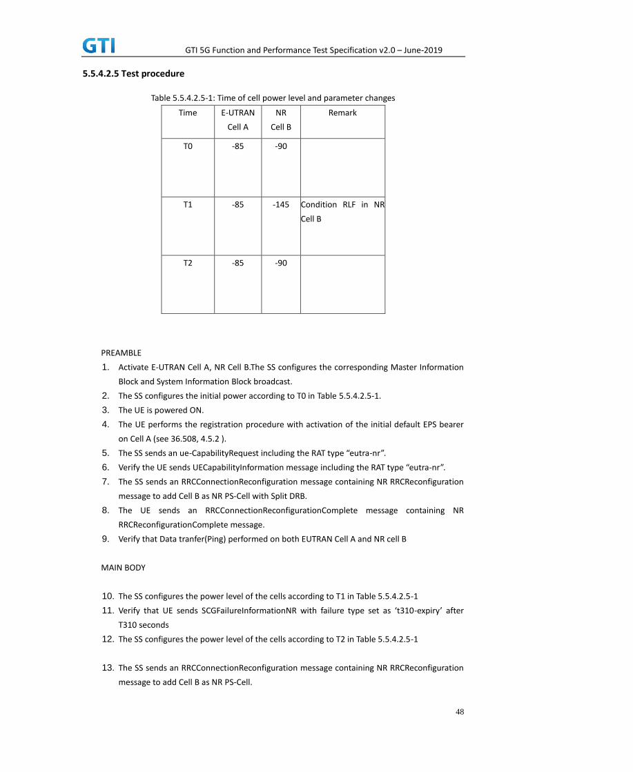
GTI 5G Function and Performance Test Specification v2.0 – June-2019
48
5.5.4.2.5 Test procedure
Table 5.5.4.2.5-1: Time of cell power level and parameter changes
Time E-UTRAN
Cell A
NR
Cell B
Remark
T0 -85 -90
T1 -85 -145 Condition RLF in NR
Cell B
T2 -85 -90
PREAMBLE
1. Activate E-UTRAN Cell A, NR Cell B.The SS configures the corresponding Master Information
Block and System Information Block broadcast.
2. The SS configures the initial power according to T0 in Table 5.5.4.2.5-1.
3. The UE is powered ON.
4. The UE performs the registration procedure with activation of the initial default EPS bearer
on Cell A (see 36.508, 4.5.2 ).
5. The SS sends an ue-CapabilityRequest including the RAT type “eutra-nr”.
6. Verify the UE sends UECapabilityInformation message including the RAT type “eutra-nr”.
7. The SS sends an RRCConnectionReconfiguration message containing NR RRCReconfiguration
message to add Cell B as NR PS-Cell with Split DRB.
8. The UE sends an RRCConnectionReconfigurationComplete message containing NR
RRCReconfigurationComplete message.
9. Verify that Data tranfer(Ping) performed on both EUTRAN Cell A and NR cell B
MAIN BODY
10. The SS configures the power level of the cells according to T1 in Table 5.5.4.2.5-1
11. Verify that UE sends SCGFailureInformationNR with failure type set as ‘t310-expiry’ after
T310 seconds
12. The SS configures the power level of the cells according to T2 in Table 5.5.4.2.5-1
13. The SS sends an RRCConnectionReconfiguration message containing NR RRCReconfiguration
message to add Cell B as NR PS-Cell.

GTI 5G Function and Performance Test Specification v2.0 – June-2019
49
14. The UE sends an RRCConnectionReconfigurationComplete message containing NR
RRCReconfigurationComplete message.
15. Verify that Data tranfer(Ping) performed on both EUTRAN Cell A and NR cell B
POSTAMBLE
16. The SS initiates a Detach procedure.
17. The SS initiates a RRC release procedure.
18. Deactivate E-UTRAN Cell A and NR Cell B.
Table 5.1.1.5-2: Message Sequence
Step Message Sequence Verdict
U-S Layer Message Specific Contents
Connect the power consumption tester to
the UE
1 RRC Activate E-UTRAN Cell A and NR Cell B.
2 SS configures the initial power according to
T0 in Table 5.5.4.2.5-1
3 UE Switch On UE AT Command
4
NAS
RRC
UE performs the registration procedure with
activation of the initial default EPS bearer on
Cell A (see 36.508, 4.5.2 ).
PASS
5 RRC The SS sends an ue-CapabilityRequest
including the RAT type “eutra-nr”.
6 RRC Verify the UE sends UECapabilityInformation
message including the RAT type “eutra-nr”.
PASS
7 NAS
RRC
SS sends an RRCConnectionReconfiguration
message containing NR RRCReconfiguration
message to add Cell B as NR PS-Cell with Split
DRB.
8 RRC UE sends an
RRCConnectionReconfigurationComplete
message containing NR
RRCReconfigurationComplete message.
PASS
9 Verify the data transmission is performed
successfully on both EUTRAN Cell A and NR
Cell B.
PASS
10 SS configures the cell power according to T1
in Table 5.5.4.2.5-1
11 RRC Verify that after T310 expiry, UE is sending
SCGFailureInformationNR with failure type
set as ‘t310-expiry’
PASS
12 SS configures the cell power according to T2
in Table 5.5.4.2.5-1
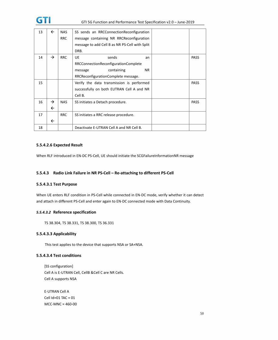
GTI 5G Function and Performance Test Specification v2.0 – June-2019
50
13 NAS
RRC
SS sends an RRCConnectionReconfiguration
message containing NR RRCReconfiguration
message to add Cell B as NR PS-Cell with Split
DRB.
14 RRC UE sends an
RRCConnectionReconfigurationComplete
message containing NR
RRCReconfigurationComplete message.
PASS
15 Verify the data transmission is performed
successfully on both EUTRAN Cell A and NR
Cell B.
PASS
16
NAS SS initiates a Detach procedure. PASS
17
RRC SS initiates a RRC release procedure.
18 Deactivate E-UTRAN Cell A and NR Cell B.
5.5.4.2.6 Expected Result
When RLF introduced in EN-DC PS-Cell, UE should initiate the SCGFailureInformationNR message
5.5.4.3 Radio Link Failure in NR PS-Cell – Re-attaching to different PS-Cell
5.5.4.3.1 Test Purpose
When UE enters RLF condition in PS-Cell while connected in EN-DC mode, verify whether it can detect
and attach in different PS-Cell and enter again to EN-DC connected mode with Data Continuity.
5.5.4.3.2 Reference specification
TS 38.304, TS 38.331, TS 38.300, TS 36.331
5.5.4.3.3 Applicability
This test applies to the device that supports NSA or SA+NSA.
5.5.4.3.4 Test conditions
[SS configuration]
Cell A is E-UTRAN Cell, CellB &Cell C are NR Cells.
Cell A supports NSA
E-UTRAN Cell A
Cell Id=01 TAC = 01
MCC-MNC = 460-00

GTI 5G Function and Performance Test Specification v2.0 – June-2019
51
E-UTRA Band = 39
EARFCN= f1
Bandwidth = 20 MHz
rootSequenceIndex TDD = 0
Reference Signal EPRE= -85 dBm/15kHz
upperLayerIndication-r15=true
NR Cell B
Cell Id=02 TAC = 01
MCC = 460 MNC = 00
NR Band = n41
NR-ARFCN= f1
Bandwidth = 100 MHz
SS/PBCH SSS EPRE = -125 dBm/30kHz
NR Cell C
Cell Id=03 TAC = 01
MCC = 460 MNC = 00
NR Band = n41
NR-ARFCN= f1
Bandwidth = 100 MHz
SS/PBCH SSS EPRE = -125 dBm/30kHz
[UE configuration]
The test UICC with USIM should be inserted
The UE is in AUTOMATIC network selection mode.
UE works in SA mode.
[Initial conditions]
SS
E-UTRAN Cell A is not active
NR Cell B is not active
NR Cell C is not active
The test shall be performed under ideal radio conditions.
UE
UE is powered off
5.5.4.3.5 Test procedure
Table 5.5.4.3.5-1: Time of cell power level and parameter changes

GTI 5G Function and Performance Test Specification v2.0 – June-2019
52
Time E-UTRAN
Cell A
NR
Cell B
NR
Cell C
Remark
T0 -85 -90 NA
T1 -85 -145 -90 Condition RLF in NR Cell B
PREAMBLE
1. Activate E-UTRAN Cell A, NR Cell B.The SS configures the corresponding Master Information
Block and System Information Block broadcast.
2. The SS configures the initial power according to T0 in Table 5.5.4.3.5-1.
3. The UE is powered ON.
4. The UE performs the registration procedure with activation of the initial default EPS bearer
on Cell A (see 36.508, 4.5.2 ).
5. The SS sends an ue-CapabilityRequest including the RAT type “eutra-nr”.
6. Verify the UE sends UECapabilityInformation message including the RAT type “eutra-nr”.
7. The SS sends an RRCConnectionReconfiguration message containing NR RRCReconfiguration
message to add Cell B as NR PS-Cell. RRCConnectionReconfiguration message contains the
ACTIVATE DEDICATED EPS BEARER CONTEXT REQUEST message
8. The UE sends an RRCConnectionReconfigurationComplete message containing NR
RRCReconfigurationComplete message.
9. The UE sends an ULInformationTransfer message containing the ACTIVATE DEDICATED EPS
BEARER CONTEXT ACCEPT message.
10. Verify that Data tranfer(Ping) performed on both EUTRAN Cell A and NR cell B
MAIN BODY
11. The SS configures the power level of the cells according to T1 in Table 5.5.4.3.5-1
12. Verify that UE sends SCGFailureInformationNR with failure type set as ‘t310-expiry’ after
T310 seconds
13. The SS sends an RRCConnectionReconfiguration message containing NR RRCReconfiguration
message to add Cell C as NR PS-Cell.
14. The UE sends an RRCConnectionReconfigurationComplete message containing NR
RRCReconfigurationComplete message.
15. Verify that Data tranfer(Ping) performed on both EUTRAN Cell A and NR cell C
POSTAMBLE
16. The SS initiates a Detach procedure.
17. The SS initiates a RRC release procedure.

GTI 5G Function and Performance Test Specification v2.0 – June-2019
53
18. Deactivate E-UTRAN Cell A and NR Cell B.
Table 5.1.1.5-2: Message Sequence
Step Message Sequence Verdict
U-S Layer Message Specific Contents
Connect the power consumption tester to
the UE
1 RRC Activate E-UTRAN Cell A and NR Cell B.
2 SS configures the initial power according to
T0 in Table 5.5.4.3.5-1
3 UE Switch On UE AT Command
4
NAS
RRC
UE performs the registration procedure with
activation of the initial default EPS bearer on
Cell A (see 36.508, 4.5.2 ).
PASS
5 RRC The SS sends an ue-CapabilityRequest
including the RAT type “eutra-nr”.
6 RRC Verify the UE sends UECapabilityInformation
message including the RAT type “eutra-nr”.
PASS
7 NAS
RRC
SS sends an RRCConnectionReconfiguration
message containing NR RRCReconfiguration
message to add Cell B as NR PS-Cell with Split
DRB. RRCConnectionReconfiguration
message contains the ACTIVATE DEDICATED
EPS BEARER CONTEXT REQUEST message.
8 RRC UE sends an
RRCConnectionReconfigurationComplete
message containing NR
RRCReconfigurationComplete message.
PASS
9 NAS
RRC
UE sends an ULInformationTransfer message
containing the ACTIVATE DEDICATED EPS
BEARER CONTEXT ACCEPT message
PASS
10 Verify the data transmission is performed
successfully on both EUTRAN Cell A and NR
Cell B.
PASS
11 SS configures the cell power according to T1
in Table 5.5.4.3.5-1
12 RRC Verify that after T310 expiry, UE is sending
SCGFailureInformationNR with failure type
set as ‘t310-expiry’
PASS
13 NAS
RRC
SS sends an RRCConnectionReconfiguration
message containing NR RRCReconfiguration
message to add Cell C as NR PS-Cell with Split
DRB.

GTI 5G Function and Performance Test Specification v2.0 – June-2019
54
14 RRC UE sends an
RRCConnectionReconfigurationComplete
message containing NR
RRCReconfigurationComplete message.
PASS
15 Verify the data transmission is performed
successfully on both EUTRAN Cell A and NR
Cell B.
PASS
16
NAS SS initiates a Detach procedure. PASS
17
RRC SS initiates a RRC release procedure.
18 Deactivate E-UTRAN Cell A and NR Cell C.
5.5.4.3.6 Expected Result
When RLF introduced in EN-DC PS-Cell, UE should initiate the SCGFailureInformationNR message
5.5.4.4 Radio Link Failure Detection and Recovery in PS-Cell
5.5.4.4.1 Test Purpose
When UE enters RLF condition in PS-Cell while connected in EN-DC mode, verify whether it can detect
and recover in same PS-Cell with Data Continuity.
5.5.4.4.2 Reference specification
TS 38.304, TS 38.331, TS 38.300, TS 36.331
5.5.4.4.3 Applicability
This test applies to the device that supports NSA or SA+NSA.
5.5.4.4.4 Test conditions
[SS configuration]
Cell A is E-UTRAN Cell, CellB is a NR Cell.
Cell A supports NSA
E-UTRAN Cell A
Cell Id=01 TAC = 01
MCC-MNC = 460-00
E-UTRA Band = 39
EARFCN= f1
Bandwidth = 20 MHz
rootSequenceIndex TDD = 0
Reference Signal EPRE= -85 dBm/15kHz

GTI 5G Function and Performance Test Specification v2.0 – June-2019
55
upperLayerIndication-r15=true
NR Cell B
Cell Id=02 TAC = 01
MCC = 460 MNC = 00
NR Band = n41
NR-ARFCN= f1
Bandwidth = 100 MHz
SS/PBCH SSS EPRE = -125 dBm/30kHz
[UE configuration]
The test UICC with USIM should be inserted
The UE is in AUTOMATIC network selection mode.
UE works in SA mode.
[Initial conditions]
SS
E-UTRAN Cell A is not active
NR Cell B is not active
The test shall be performed under ideal radio conditions.
UE
UE is powered off
5.5.4.4.5 Test procedure
Table 5.5.4.4.5-1: Time of cell power level and parameter changes
Time E-UTRAN
Cell A
NR
Cell B
Remark
T0 -85 -90
T1 -85 -145 Condition RLF in NR
Cell B
T2 -85 -90
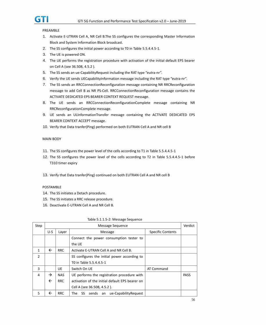
GTI 5G Function and Performance Test Specification v2.0 – June-2019
56
PREAMBLE
1. Activate E-UTRAN Cell A, NR Cell B.The SS configures the corresponding Master Information
Block and System Information Block broadcast.
2. The SS configures the initial power according to T0 in Table 5.5.4.4.5-1.
3. The UE is powered ON.
4. The UE performs the registration procedure with activation of the initial default EPS bearer
on Cell A (see 36.508, 4.5.2 ).
5. The SS sends an ue-CapabilityRequest including the RAT type “eutra-nr”.
6. Verify the UE sends UECapabilityInformation message including the RAT type “eutra-nr”.
7. The SS sends an RRCConnectionReconfiguration message containing NR RRCReconfiguration
message to add Cell B as NR PS-Cell. RRCConnectionReconfiguration message contains the
ACTIVATE DEDICATED EPS BEARER CONTEXT REQUEST message.
8. The UE sends an RRCConnectionReconfigurationComplete message containing NR
RRCReconfigurationComplete message.
9. UE sends an ULInformationTransfer message containing the ACTIVATE DEDICATED EPS
BEARER CONTEXT ACCEPT message.
10. Verify that Data tranfer(Ping) performed on both EUTRAN Cell A and NR cell B
MAIN BODY
11. The SS configures the power level of the cells according to T1 in Table 5.5.4.4.5-1
12. The SS configures the power level of the cells according to T2 in Table 5.5.4.4.5-1 before
T310 timer expiry
13. Verify that Data tranfer(Ping) continued on both EUTRAN Cell A and NR cell B
POSTAMBLE
14. The SS initiates a Detach procedure.
15. The SS initiates a RRC release procedure.
16. Deactivate E-UTRAN Cell A and NR Cell B.
Table 5.1.1.5-2: Message Sequence
Step Message Sequence Verdict
U-S Layer Message Specific Contents
Connect the power consumption tester to
the UE
1 RRC Activate E-UTRAN Cell A and NR Cell B.
2 SS configures the initial power according to
T0 in Table 5.5.4.4.5-1
3 UE Switch On UE AT Command
4
NAS
RRC
UE performs the registration procedure with
activation of the initial default EPS bearer on
Cell A (see 36.508, 4.5.2 ).
PASS
5 RRC The SS sends an ue-CapabilityRequest

GTI 5G Function and Performance Test Specification v2.0 – June-2019
57
including the RAT type “eutra-nr”.
6 RRC Verify the UE sends UECapabilityInformation
message including the RAT type “eutra-nr”.
PASS
7 NAS
RRC
SS sends an RRCConnectionReconfiguration
message containing NR RRCReconfiguration
message to add Cell B as NR PS-Cell with Split
DRB. RRCConnectionReconfiguration
message contains the ACTIVATE DEDICATED
EPS BEARER CONTEXT REQUEST message.
8 RRC UE sends an
RRCConnectionReconfigurationComplete
message containing NR
RRCReconfigurationComplete message.
PASS
9 NAS
RRC
UE sends an ULInformationTransfer message
containing the ACTIVATE DEDICATED EPS
BEARER CONTEXT ACCEPT message
PASS
10 Verify the data transmission is performed
successfully on both EUTRAN Cell A and NR
Cell B.
PASS
11 SS configures the cell power according to T1
in Table 5.5.4.4.5-1
12 SS configures the cell power according to T2
in Table 5.5.4.4.5-1 before T310 expiry
13 Verify the data transmission is continued
successfully on both EUTRAN Cell A and NR
Cell B.
PASS
14
NAS SS initiates a Detach procedure. PASS
15
RRC SS initiates a RRC release procedure.
16 Deactivate E-UTRAN Cell A and NR Cell B.
5.5.4.4.6 Expected Result
When RLF introduced and resolved before T310 expiry in EN-DC PS-Cell, UE should detect and recover
from the RLF and continue the data transmission
5.6 CSI-RS Measurement
5.6.1 CSI Reporting Periodic in PUSCH

GTI 5G Function and Performance Test Specification v2.0 – June-2019
58
5.6.1.1 Test Purpose
Periodic CSI measurement configuration for CSI type 1 in NR cell when UE is connected to EN-DC.
5.6.1.2 Reference specification
TS 36.304, clause 5.2.4, TS 38.213, 38.331
5.6.1.3 Applicability
This test applies to the device that supports NSA or SA+NSA.
5.6.1.4 Test conditions
[SS configuration]
Cell A is E-UTRAN Cell, CellB is a NR Cell.
Cell A supports NSA
E-UTRAN Cell A
Cell Id=01 TAC = 01
MCC-MNC = 460-00
EARFCN= f1
rootSequenceIndex = 0
Reference Signal EPRE= -85 dBm/15kHz
upperLayerIndication-r15=true
NR Cell B
Cell Id=02 TAC = 01
MCC = 460 MNC = 00
NR-ARFCN= f1
SS/PBCH SSS EPRE = -125 dBm/30kHz
[UE configuration]
The test UICC with USIM should be inserted
The UE is in AUTOMATIC network selection mode.
UE works in NSA mode.
[Initial conditions]
SS
E-UTRAN Cell A is not active
NR Cell B is not active
The test shall be performed under ideal radio conditions.
UE
UE is powered off
5.6.1.5 Test procedure

GTI 5G Function and Performance Test Specification v2.0 – June-2019
59
Table 5.1.1.5-1: Time of cell power level and parameter changes
Time E-UTRAN Cell A NR Cell B Remark
T0 -85 -90
PREAMBLE
1. Activate E-UTRAN Cell A, NR Cell B.The SS configures the corresponding Master Information
Block and System Information Block broadcast.
2. The SS configures the initial power according to T0 in Table 5.6.1.5-1.
3. The UE is powered ON.
4. The UE performs the registration procedure with activation of the initial default EPS bearer
on Cell A (see 36.508, 4.5.2 ).
5. The SS sends an ue-CapabilityRequest including the RAT type “eutra-nr”.
6. Verify the UE sends UECapabilityInformation message including the RAT type “eutra-nr”.
7. The SS sends an RRCConnectionReconfiguration message containing NR RRCReconfiguration
message to add Cell B as NR PS-Cell with Split DRB.
8. The UE sends an RRCConnectionReconfigurationComplete message containing NR
RRCReconfigurationComplete message.
9. Verify that Data tranfer(Ping) perofrmed on NR cell B
MAIN BODY
10. Send RRCConnectionReconfiguration message containing NR RRCReconfiguration to
configure NR Measurement Objects, Report configuration, Report Quantity, Codebook
Configuration(Type 1), Resource periodicity and offset to the UE
11. The UE sends an RRCConnectionReconfigurationComplete message containing NR
RRCReconfigurationComplete message.
12. Verify that CSI-RS measurements are received for the NR cell
POSTAMBLE
13. The SS initiates a Detach procedure.
14. The SS initiates a RRC release procedure.
15. Deactivate E-UTRAN Cell A and NR Cell B.
Table 5.6.1.55.1.1.5-2: Message Sequence
Step Message Sequence Verdict
U-S Layer Message Specific Contents
Connect the power consumption tester to
the UE
1 RRC Activate E-UTRAN Cell A and NR Cell B.
2 SS configures the initial power according to
T0 in Table 5.6.1.5-1.
3 UE Switch On UE AT Command
4
NAS
RRC
UE performs the registration procedure with
activation of the initial default EPS bearer on
PASS

GTI 5G Function and Performance Test Specification v2.0 – June-2019
60
Cell A (see 36.508, 4.5.2 ).
5 RRC The SS sends an ue-CapabilityRequest
including the RAT type “eutra-nr”.
6 RRC Verify the UE sends UECapabilityInformation
message including the RAT type “eutra-nr”.
7 NAS
RRC
SS sends an RRCConnectionReconfiguration
message containing NR RRCReconfiguration
message to add Cell B as NR PS-Cell with Split
DRB.
8 RRC UE sends an
RRCConnectionReconfigurationComplete
message containing NR
RRCReconfigurationComplete message.
PASS
9 Verify the data transmission is performed
successfully on NR Cell B.
PASS
10 RRC SS sends an RRCConnectionReconfiguration
message containing NR RRCReconfiguration
message to configure the Periodic CSI-RS
Measurements
11 RRC UE sends an
RRCConnectionReconfigurationComplete
message containing NR
RRCReconfigurationComplete message.
12 Verify that periodic CSI-RS measurements are
received
PASS
13
NAS SS initiates a Detach procedure. PASS
14 RRC SS initiates a RRC release procedure.
15 Deactivate E-UTRAN Cell A and NR Cell B.
5.6.1.6 Expected Result
Verify that UE sends periodic CSI-RS measurements in PUCCH for NR cell
5.6.2 CSI Reporting Aperiodic in PUSCH
5.6.2.1 Test Purpose
Aperiodic CSI measurement configuration for CSI type 1 in NR cell when UE is connected to
EN-DC.
5.6.2.2 Reference specification
TS 36.304, clause 5.2.4, TS 38.213, 38.331
5.6.2.3 Applicability

GTI 5G Function and Performance Test Specification v2.0 – June-2019
61
This test applies to the device that supports NSA or SA+NSA.
5.6.2.4 Test conditions
[SS configuration]
Cell A is E-UTRAN Cell, CellB is a NR Cell.
Cell A supports NSA
E-UTRAN Cell A
Cell Id=01 TAC = 01
MCC-MNC = 460-00
EARFCN= f1
rootSequenceIndex = 0
Reference Signal EPRE= -85 dBm/15kHz
upperLayerIndication-r15=true
NR Cell B
Cell Id=02 TAC = 01
MCC = 460 MNC = 00
NR-ARFCN= f1
SS/PBCH SSS EPRE = -125 dBm/30kHz
[UE configuration]
The test UICC with USIM should be inserted
The UE is in AUTOMATIC network selection mode.
UE works in NSA mode.
[Initial conditions]
SS
E-UTRAN Cell A is not active
NR Cell B is not active
The test shall be performed under ideal radio conditions.
UE
UE is powered off
5.6.2.5 Test procedure
Table 5.1.1.5-1: Time of cell power level and parameter changes
Time E-UTRAN Cell A NR Cell B Remark
T0 -85 -90
PREAMBLE
1. Activate E-UTRAN Cell A, NR Cell B.The SS configures the corresponding Master Information
Block and System Information Block broadcast.

GTI 5G Function and Performance Test Specification v2.0 – June-2019
62
2. The SS configures the initial power according to T0 in Table 5.6.2.5-1.
3. The UE is powered ON.
4. The UE performs the registration procedure with activation of the initial default EPS bearer
on Cell A (see 36.508, 4.5.2 ).
5. The SS sends an ue-CapabilityRequest including the RAT type “eutra-nr”.
6. Verify the UE sends UECapabilityInformation message including the RAT type “eutra-nr”.
7. The SS sends an RRCConnectionReconfiguration message containing NR RRCReconfiguration
message to add Cell B as NR PS-Cell with Split DRB.
8. The UE sends an RRCConnectionReconfigurationComplete message containing NR
RRCReconfigurationComplete message.
9. Verify that Data tranfer(Ping) perofrmed on NR cell B
MAIN BODY
10. Send RRCConnectionReconfiguration message containing NR RRCReconfiguration to
configure NR Measurement Objects, Report configuration, Report Quantity, Codebook
Configuration(Type 1), Resource periodicity and offset to the UE
11. The UE sends an RRCConnectionReconfigurationComplete message containing NR
RRCReconfigurationComplete message.
12. SS sends DCI to trigger the Aperiodic CSI-RS Measurements to the UE
13. Verify that CSI-RS measurements are received for the NR cell
POSTAMBLE
14. The SS initiates a Detach procedure.
15. The SS initiates a RRC release procedure.
16. Deactivate E-UTRAN Cell A and NR Cell B.
Table 5.6.2.55.1.1.5-2: Message Sequence
Step Message Sequence Verdict
U-S Layer Message Specific Contents
Connect the power consumption tester to
the UE
1 RRC Activate E-UTRAN Cell A and NR Cell B.
2 SS configures the initial power according to
T0 in Table 5.6.2.5-1.
3 UE Switch On UE AT Command
4
NAS
RRC
UE performs the registration procedure with
activation of the initial default EPS bearer on
Cell A (see 36.508, 4.5.2 ).
PASS
5 RRC The SS sends an ue-CapabilityRequest
including the RAT type “eutra-nr”.
6 RRC Verify the UE sends UECapabilityInformation
message including the RAT type “eutra-nr”.
7 NAS
RRC
SS sends an RRCConnectionReconfiguration
message containing NR RRCReconfiguration

GTI 5G Function and Performance Test Specification v2.0 – June-2019
63
message to add Cell B as NR PS-Cell with Split
DRB.
8 RRC UE sends an
RRCConnectionReconfigurationComplete
message containing NR
RRCReconfigurationComplete message.
PASS
9 Verify the data transmission is performed
successfully on NR Cell B.
PASS
10 RRC SS sends an RRCConnectionReconfiguration
message containing NR RRCReconfiguration
message to configure the Periodic CSI-RS
Measurements
11 RRC UE sends an
RRCConnectionReconfigurationComplete
message containing NR
RRCReconfigurationComplete message.
12 SS sends DCI to trigger Aperiodic CSI-RS
measurements to the UE
13 Verify that Aperiodic CSI-RS measurements
are received
PASS
14
NAS SS initiates a Detach procedure. PASS
15 RRC SS initiates a RRC release procedure.
16 Deactivate E-UTRAN Cell A and NR Cell B.
5.6.2.6 Expected Result
Verify that UE sends aperiodic CSI-RS measurements in PUSCH for NR cell
5.6.3 CSI Reporting Aperiodic in PUSCH
5.6.3.1 Test Purpose
Aperiodic CSI measurement configuration for CSI type 1 in NR CA cell when UE is connected to
EN-DC.
5.6.3.2 Reference specification
TS 36.304, clause 5.2.4, TS 38.213, 38.331
5.6.3.3 Applicability
This test applies to the device that supports NSA or SA+NSA.
5.6.3.4 Test conditions

GTI 5G Function and Performance Test Specification v2.0 – June-2019
64
[SS configuration]
Cell A is E-UTRAN Cell, Cell B and Cell C are NR Cells.
Cell A supports NSA
E-UTRAN Cell A
Cell Id=01 TAC = 01
MCC-MNC = 460-00
EARFCN= f1
rootSequenceIndex= 0
Reference Signal EPRE= -85 dBm/15kHz
upperLayerIndication-r15=true
NR Cell B
Cell Id=02 TAC = 01
MCC = 460 MNC = 00
NR-ARFCN= f1
SS/PBCH SSS EPRE = -125 dBm/30kHz
NR Cell C
Cell Id=03 TAC = 01
MCC = 460 MNC = 00
NR-ARFCN= f1
SS/PBCH SSS EPRE = -125 dBm/30kHz
[UE configuration]
The test UICC with USIM should be inserted
The UE is in AUTOMATIC network selection mode.
UE works in NSA mode.
[Initial conditions]
SS
E-UTRAN Cell A is not active
NR Cell B is not active
NR Cell C is not active
The test shall be performed under ideal radio conditions.
UE
UE is powered off
5.6.3.5 Test procedure
Table 5.1.1.5-1: Time of cell power level and parameter changes
Time E-UTRAN Cell A NR Cell B NR Cell C Remark
T0 -85 -90 -95
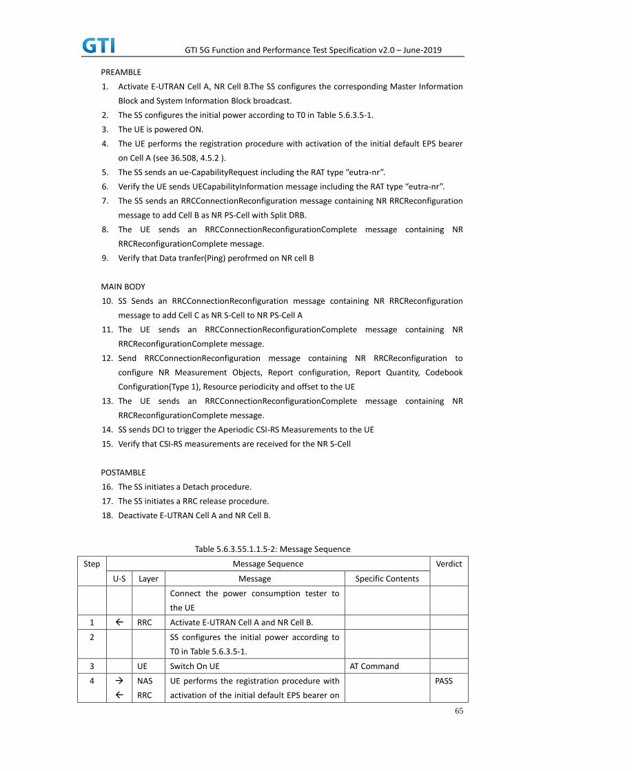
GTI 5G Function and Performance Test Specification v2.0 – June-2019
65
PREAMBLE
1. Activate E-UTRAN Cell A, NR Cell B.The SS configures the corresponding Master Information
Block and System Information Block broadcast.
2. The SS configures the initial power according to T0 in Table 5.6.3.5-1.
3. The UE is powered ON.
4. The UE performs the registration procedure with activation of the initial default EPS bearer
on Cell A (see 36.508, 4.5.2 ).
5. The SS sends an ue-CapabilityRequest including the RAT type “eutra-nr”.
6. Verify the UE sends UECapabilityInformation message including the RAT type “eutra-nr”.
7. The SS sends an RRCConnectionReconfiguration message containing NR RRCReconfiguration
message to add Cell B as NR PS-Cell with Split DRB.
8. The UE sends an RRCConnectionReconfigurationComplete message containing NR
RRCReconfigurationComplete message.
9. Verify that Data tranfer(Ping) perofrmed on NR cell B
MAIN BODY
10. SS Sends an RRCConnectionReconfiguration message containing NR RRCReconfiguration
message to add Cell C as NR S-Cell to NR PS-Cell A
11. The UE sends an RRCConnectionReconfigurationComplete message containing NR
RRCReconfigurationComplete message.
12. Send RRCConnectionReconfiguration message containing NR RRCReconfiguration to
configure NR Measurement Objects, Report configuration, Report Quantity, Codebook
Configuration(Type 1), Resource periodicity and offset to the UE
13. The UE sends an RRCConnectionReconfigurationComplete message containing NR
RRCReconfigurationComplete message.
14. SS sends DCI to trigger the Aperiodic CSI-RS Measurements to the UE
15. Verify that CSI-RS measurements are received for the NR S-Cell
POSTAMBLE
16. The SS initiates a Detach procedure.
17. The SS initiates a RRC release procedure.
18. Deactivate E-UTRAN Cell A and NR Cell B.
Table 5.6.3.55.1.1.5-2: Message Sequence
Step Message Sequence Verdict
U-S Layer Message Specific Contents
Connect the power consumption tester to
the UE
1 RRC Activate E-UTRAN Cell A and NR Cell B.
2 SS configures the initial power according to
T0 in Table 5.6.3.5-1.
3 UE Switch On UE AT Command
4
NAS
RRC
UE performs the registration procedure with
activation of the initial default EPS bearer on
PASS

GTI 5G Function and Performance Test Specification v2.0 – June-2019
66
Cell A (see 36.508, 4.5.2 ).
5 RRC The SS sends an ue-CapabilityRequest
including the RAT type “eutra-nr”.
6 RRC Verify the UE sends UECapabilityInformation
message including the RAT type “eutra-nr”.
7 NAS
RRC
SS sends an RRCConnectionReconfiguration
message containing NR RRCReconfiguration
message to add Cell B as NR PS-Cell with Split
DRB.
8 RRC UE sends an
RRCConnectionReconfigurationComplete
message containing NR
RRCReconfigurationComplete message.
PASS
9 Verify the data transmission is performed
successfully on NR Cell B.
PASS
10 RRC SS sends an RRCConnectionReconfiguration
message containing NR RRCReconfiguration
message to add NR Cell C as NR S-Cell to NR
PS-Cell B
11 RRC UE sends an
RRCConnectionReconfigurationComplete
message containing NR
RRCReconfigurationComplete message.
PASS
12 RRC SS sends an RRCConnectionReconfiguration
message containing NR RRCReconfiguration
message to configure the Periodic CSI-RS
Measurements
13 RRC UE sends an
RRCConnectionReconfigurationComplete
message containing NR
RRCReconfigurationComplete message.
14 SS sends DCI to trigger Aperiodic CSI-RS
measurements to the UE
15 Verify that Aperiodic CSI-RS measurements
are received for NR cell C
PASS
16
NAS SS initiates a Detach procedure. PASS
17 RRC SS initiates a RRC release procedure.
18 Deactivate E-UTRAN Cell A and NR Cell B.
5.6.3.6 Expected Result
Verify that UE sends aperiodic CSI-RS measurements in PUSCH for NR cell C
5.6.4 CSI-RS Based Intra Frequency Measurements on Neighbour Cell Beams

GTI 5G Function and Performance Test Specification v2.0 – June-2019
67
5.6.4.1 Test Purpose
Verify that When CSI-RSRP measurements are activated for multiple neigbour beam indexes, UE
reports the beam indexes properly
5.6.4.2 Reference specification
TS 36.304, clause 5.2.4, TS 38.213, 38.331
5.6.4.3 Applicability
This test applies to the device that supports NSA or SA+NSA.
5.6.4.4 Test conditions
[SS configuration]
Cell A is E-UTRAN Cell, Cell B and Cell C are intra frequency NR Cells.
Cell A supports NSA
E-UTRAN Cell A
Cell Id=01 TAC = 01
MCC-MNC = 460-00
EARFCN= f1
rootSequenceIndex= 0
Reference Signal EPRE= -85 dBm/15kHz
upperLayerIndication-r15=true
NR Cell B
Cell Id=02 TAC = 01
MCC = 460 MNC = 00
NR-ARFCN= f1
SS/PBCH SSS EPRE = -125 dBm/30kHz
NR Cell C
Cell Id=03 TAC = 01
MCC = 460 MNC = 00
NR-ARFCN= f1
SS/PBCH SSS EPRE for Beam 1 = -125 dBm/30kHz
SS/PBCH SSS EPRE for Beam 2 = -125 dBm/30kHz
[UE configuration]
The test UICC with USIM should be inserted
The UE is in AUTOMATIC network selection mode.
UE works in NSA mode.
[Initial conditions]

GTI 5G Function and Performance Test Specification v2.0 – June-2019
68
SS
E-UTRAN Cell A is not active
NR Cell B is not active
NR Cell C is not active
The test shall be performed under ideal radio conditions.
UE
UE is powered off
5.6.4.5 Test procedure
Table 5.1.1.5-1: Time of cell power level and parameter changes
Time E-UTRAN Cell A NR Cell B NR Cell C Remark
T0 -85 -90 -98
T1 -85 -106 -98
PREAMBLE
1. Activate E-UTRAN Cell A, NR Cell B.The SS configures the corresponding Master Information
Block and System Information Block broadcast.
2. The SS configures the initial power according to T0 in Table 5.6.4.5-1.
3. The UE is powered ON.
4. The UE performs the registration procedure with activation of the initial default EPS bearer
on Cell A (see 36.508, 4.5.2 ).
5. The SS sends an ue-CapabilityRequest including the RAT type “eutra-nr”.
6. Verify the UE sends UECapabilityInformation message including the RAT type “eutra-nr”.
7. The SS sends an RRCConnectionReconfiguration message containing NR RRCReconfiguration
message to add Cell B as NR PS-Cell with Split DRB.
8. The UE sends an RRCConnectionReconfigurationComplete message containing NR
RRCReconfigurationComplete message.
9. Verify that Data tranfer(Ping) perofrmed on NR cell B
MAIN BODY
10. SS Sends an RRCConnectionReconfiguration message containing NR RRCReconfiguration
message to configure the measurement configuration to setup a SS/PBCH block based intra
frequency NR measurements for NR cell B and reporting event A3
11. The UE sends an RRCConnectionReconfigurationComplete message containing NR
RRCReconfigurationComplete message.
12. SS reconfigures the cell power level according to T1 in Table 5.6.4.5-1
13. Verify that UE sends measured result for Event A3 with beam information containing
RsIndex[0] and RsIndex[1] for neighbour NR cell C
POSTAMBLE
14. The SS initiates a Detach procedure.

GTI 5G Function and Performance Test Specification v2.0 – June-2019
69
15. The SS initiates a RRC release procedure.
16. Deactivate E-UTRAN Cell A and NR Cell B.
Table 5.6.4.55.1.1.5-2: Message Sequence
Step Message Sequence Verdict
U-S Layer Message Specific Contents
Connect the power consumption tester to
the UE
1 RRC Activate E-UTRAN Cell A and NR Cell B.
2 SS configures the initial power according to
T0 in Table 5.6.4.5-1.
3 UE Switch On UE AT Command
4
NAS
RRC
UE performs the registration procedure with
activation of the initial default EPS bearer on
Cell A (see 36.508, 4.5.2 ).
PASS
5 RRC The SS sends an ue-CapabilityRequest
including the RAT type “eutra-nr”.
6 RRC Verify the UE sends UECapabilityInformation
message including the RAT type “eutra-nr”.
7 NAS
RRC
SS sends an RRCConnectionReconfiguration
message containing NR RRCReconfiguration
message to add Cell B as NR PS-Cell with Split
DRB.
8 RRC UE sends an
RRCConnectionReconfigurationComplete
message containing NR
RRCReconfigurationComplete message.
PASS
9 Verify the data transmission is performed
successfully on NR Cell B.
PASS
10 RRC SS sends an RRCConnectionReconfiguration
message containing NR RRCReconfiguration
message to configure the measurement
configuration to setup a SS/PBCH block based
intra frequency NR measurements for NR cell
B and reporting event A3
11 RRC UE sends an
RRCConnectionReconfigurationComplete
message containing NR
RRCReconfigurationComplete message.
PASS
12 RRC SS reconfigures the cell power level according
to T1 in Table 5.6.4.5-1
13 RRC UE sends measured result in Measurement
report for Event A3 with beam information
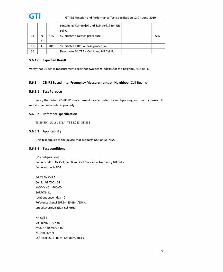
GTI 5G Function and Performance Test Specification v2.0 – June-2019
70
containing RsIndex[0] and RsIndex[1] for NR
cell C
14
NAS SS initiates a Detach procedure. PASS
15 RRC SS initiates a RRC release procedure.
16 Deactivate E-UTRAN Cell A and NR Cell B.
5.6.4.6 Expected Result
Verify that UE sends measurement report for two beam indexes for the neighbour NR cell C
5.6.5 CSI-RS Based Inter Frequency Measurements on Neighbour Cell Beams
5.6.5.1 Test Purpose
Verify that When CSI-RSRP measurements are activated for multiple neigbour beam indexes, UE
reports the beam indexes properly
5.6.5.2 Reference specification
TS 36.304, clause 5.2.4, TS 38.213, 38.331
5.6.5.3 Applicability
This test applies to the device that supports NSA or SA+NSA.
5.6.5.4 Test conditions
[SS configuration]
Cell A is E-UTRAN Cell, Cell B and Cell C are inter frequency NR Cells.
Cell A supports NSA
E-UTRAN Cell A
Cell Id=01 TAC = 01
MCC-MNC = 460-00
EARFCN= f1
rootSequenceIndex = 0
Reference Signal EPRE= -85 dBm/15kHz
upperLayerIndication-r15=true
NR Cell B
Cell Id=02 TAC = 01
MCC = 460 MNC = 00
NR-ARFCN= f1
SS/PBCH SSS EPRE = -125 dBm/30kHz

GTI 5G Function and Performance Test Specification v2.0 – June-2019
71
NR Cell C
Cell Id=03 TAC = 01
MCC = 460 MNC = 00
NR-ARFCN= f1
SS/PBCH SSS EPRE for Beam 1 = -125 dBm/30kHz
SS/PBCH SSS EPRE for Beam 2 = -125 dBm/30kHz
[UE configuration]
The test UICC with USIM should be inserted
The UE is in AUTOMATIC network selection mode.
UE works in NSA mode.
[Initial conditions]
SS
E-UTRAN Cell A is not active
NR Cell B is not active
NR Cell C is not active
The test shall be performed under ideal radio conditions.
UE
UE is powered off
5.6.5.5 Test procedure
Table 5.1.1.5-1: Time of cell power level and parameter changes
Time E-UTRAN Cell A NR Cell B NR Cell C Remark
T0 -85 -90 -98
T1 -85 -106 -98
PREAMBLE
1. Activate E-UTRAN Cell A, NR Cell B.The SS configures the corresponding Master Information
Block and System Information Block broadcast.
2. The SS configures the initial power according to T0 in Table 5.6.5.5-1.
3. The UE is powered ON.
4. The UE performs the registration procedure with activation of the initial default EPS bearer
on Cell A (see 36.508, 4.5.2 ).
5. The SS sends an ue-CapabilityRequest including the RAT type “eutra-nr”.
6. Verify the UE sends UECapabilityInformation message including the RAT type “eutra-nr”.
7. The SS sends an RRCConnectionReconfiguration message containing NR RRCReconfiguration
message to add Cell B as NR PS-Cell with Split DRB.
8. The UE sends an RRCConnectionReconfigurationComplete message containing NR
RRCReconfigurationComplete message.
9. Verify that Data tranfer(Ping) perofrmed on NR cell B
MAIN BODY

GTI 5G Function and Performance Test Specification v2.0 – June-2019
72
10. SS Sends an RRCConnectionReconfiguration message containing NR RRCReconfiguration
message to configure the measurement configuration to setup a SS/PBCH block based inter
frequency NR measurements for NR cell C and reporting event A3
11. The UE sends an RRCConnectionReconfigurationComplete message containing NR
RRCReconfigurationComplete message.
12. SS reconfigures the cell power level according to T1 in Table 5.6.5.5-1
13. Verify that UE sends measured result for Event A3 with beam information containing
RsIndex[0] and RsIndex[1] for neighbour NR cell C
POSTAMBLE
14. The SS initiates a Detach procedure.
15. The SS initiates a RRC release procedure.
16. Deactivate E-UTRAN Cell A and NR Cell B.
Table 5.1.1.5-2: Message Sequence
Step Message Sequence Verdict
U-S Layer Message Specific Contents
Connect the power consumption tester to
the UE
1 RRC Activate E-UTRAN Cell A and NR Cell B.
2 SS configures the initial power according to
T0 in Table 5.6.5.5-1.
3 UE Switch On UE AT Command
4
NAS
RRC
UE performs the registration procedure with
activation of the initial default EPS bearer on
Cell A (see 36.508, 4.5.2 ).
PASS
5 RRC The SS sends an ue-CapabilityRequest
including the RAT type “eutra-nr”.
6 RRC Verify the UE sends UECapabilityInformation
message including the RAT type “eutra-nr”.
7 NAS
RRC
SS sends an RRCConnectionReconfiguration
message containing NR RRCReconfiguration
message to add Cell B as NR PS-Cell with Split
DRB.
8 RRC UE sends an
RRCConnectionReconfigurationComplete
message containing NR
RRCReconfigurationComplete message.
PASS
9 Verify the data transmission is performed
successfully on NR Cell B.
PASS
10 RRC SS sends an RRCConnectionReconfiguration
message containing NR RRCReconfiguration
message to configure the measurement

GTI 5G Function and Performance Test Specification v2.0 – June-2019
73
configuration to setup a SS/PBCH block based
inter frequency NR measurements for NR cell
C and reporting event A3
11 RRC UE sends an
RRCConnectionReconfigurationComplete
message containing NR
RRCReconfigurationComplete message.
PASS
12 RRC SS reconfigures the cell power level according
to T1 in Table 5.6.5.5-1
13 RRC UE sends measured result in Measurement
report for Event A3 with beam information
containing RsIndex[0] and RsIndex[1] for NR
cell C
14
NAS SS initiates a Detach procedure. PASS
15 RRC SS initiates a RRC release procedure.
16 Deactivate E-UTRAN Cell A and NR Cell B.
5.6.5.6 Expected Result
Verify that UE sends measurement report for two beam indexes for the neighbour NR cell C
5.7 RRC Inactive mode cases in SA
5.7.1 RRC Connected Mode to RRC Inactive Mode and RRC Resume Procedure
5.7.1.1 Test Purpose
When RRC connection Release is send to UE with Suspending RRC connection verify that UE is
entering RRC Inactive mode. When Paging is sent to UE in RRC Inactive Mode verify that UE resumes
the RRC Connection by inititating RRC Resume Procedure
5.7.1.2 Reference specification
TS 38.304, TS 38.331, TS 38.300
5.7.1.3 Applicability
This test applies to the device that supports SA or SA+NSA.
5.7.1.4 Test conditions
[SS configuration]
Cell A is a NR Cell.
Cell A supports only SA
NR Cell A
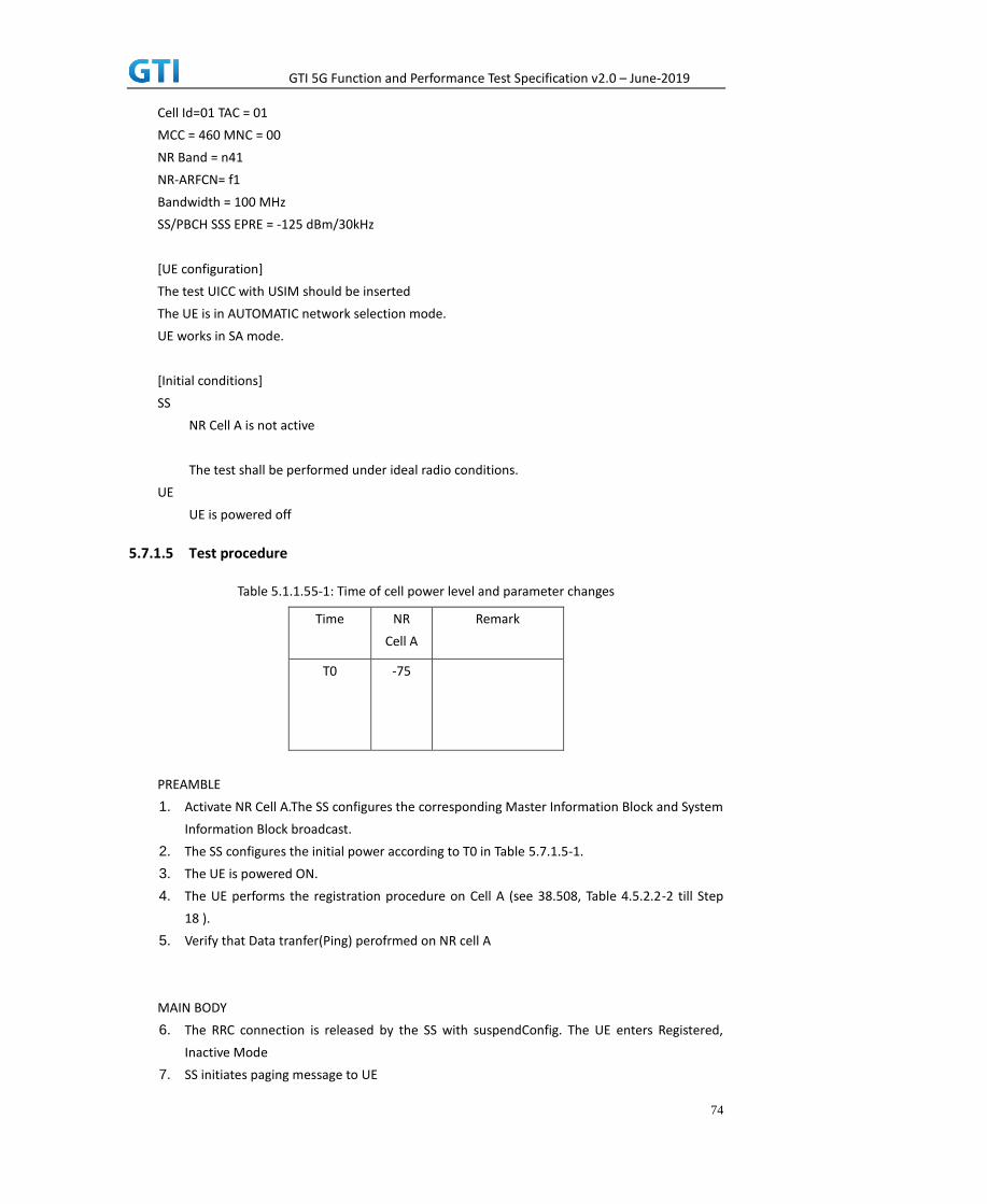
GTI 5G Function and Performance Test Specification v2.0 – June-2019
74
Cell Id=01 TAC = 01
MCC = 460 MNC = 00
NR Band = n41
NR-ARFCN= f1
Bandwidth = 100 MHz
SS/PBCH SSS EPRE = -125 dBm/30kHz
[UE configuration]
The test UICC with USIM should be inserted
The UE is in AUTOMATIC network selection mode.
UE works in SA mode.
[Initial conditions]
SS
NR Cell A is not active
The test shall be performed under ideal radio conditions.
UE
UE is powered off
5.7.1.5 Test procedure
Table 5.1.1.55-1: Time of cell power level and parameter changes
Time NR
Cell A
Remark
T0 -75
PREAMBLE
1. Activate NR Cell A.The SS configures the corresponding Master Information Block and System
Information Block broadcast.
2. The SS configures the initial power according to T0 in Table 5.7.1.5-1.
3. The UE is powered ON.
4. The UE performs the registration procedure on Cell A (see 38.508, Table 4.5.2.2-2 till Step
18 ).
5. Verify that Data tranfer(Ping) perofrmed on NR cell A
MAIN BODY
6. The RRC connection is released by the SS with suspendConfig. The UE enters Registered,
Inactive Mode
7. SS initiates paging message to UE

GTI 5G Function and Performance Test Specification v2.0 – June-2019
75
8. Verify that UE is initiating RRC Resume Procedure by sending RRCResumeRequest to SS
9. SS transmits RRCResume message to the UE
10. Verify that UE is sending RRCResumeComplete to SS
11. Verify that Data tranfer(Ping) perofrmed on NR cell A
POSTAMBLE
12. The SS initiates a Deregitration procedure.
13. The SS initiates a RRC release procedure.
14. Deactivate NR Cell A.
Table 5.1.1.5-2: Message Sequence
Step Message Sequence Verdict
U-S Layer Message Specific Contents
Connect the power consumption tester to
the UE
1 RRC Activate NR Cell A.
2 SS configures the initial power according to
T0 in Table 5.7.1.5-1.
3 UE Switch On UE AT Command
4
NAS
RRC
UE performs the registration procedure (see
38.508, Table 4.5.2.2-2 till Step 18 ).
PASS
5 Verify the data transmission is performed
successfully on NR Cell A.
PASS
6 RRC The RRC connection is released by the SS
with suspendConfig.
7 RRC Paging
8 RRC RRCResumeRequest PASS
9 RRC RRCResume
10 RRC RRCResumeComplete PASS
11 Verify the data transmission is performed
successfully on NR Cell A.
PASS
12
NAS SS initiates a Deregitration procedure. PASS
13 RRC SS initiates a RRC release procedure.
14 Deactivate NR Cell A.
5.7.1.6 Expected Result
Verify that UE moves to RRC Inactive Mode and comes back to RRC Connected mode when instructed.
5.7.2 Periodic RNA Update Procedure in RRC Inactive Mode

GTI 5G Function and Performance Test Specification v2.0 – June-2019
76
5.7.2.1 Test Purpose
When RNA Update timer expires in RRC Inactive Mode verify that UE initiates RRC Connection Resume
Procedure for RNA Update
5.7.2.2 Reference specification
TS 38.304, TS 38.331, TS 38.300
5.7.2.3 Applicability
This test applies to the device that supports SA or SA+NSA.
5.7.2.4 Test conditions
[SS configuration]
Cell A is a NR Cell.
Cell A supports only SA
NR Cell A
Cell Id=01 TAC = 01
MCC = 460 MNC = 00
NR Band = n41
NR-ARFCN= f1
Bandwidth = 100 MHz
SS/PBCH SSS EPRE = -125 dBm/30kHz
T380 = min5
[UE configuration]
The test UICC with USIM should be inserted
The UE is in AUTOMATIC network selection mode.
UE works in SA mode.
[Initial conditions]
SS
NR Cell A is not active
The test shall be performed under ideal radio conditions.
UE
UE is powered off
5.7.2.5 Test procedure
Table 5.1.1.55-1: Time of cell power level and parameter changes
Time NR
Cell A
Remark

GTI 5G Function and Performance Test Specification v2.0 – June-2019
77
T0 -75
PREAMBLE
1. Activate NR Cell A.The SS configures the corresponding Master Information Block and System
Information Block broadcast.
2. The SS configures the initial power according to T0 in Table 5.7.2.5-1.
3. The UE is powered ON.
4. The UE performs the registration procedure on Cell A (see 38.508, Table 4.5.2.2-2 till Step
18 ).
5. Verify that Data tranfer(Ping) perofrmed on NR cell A
MAIN BODY
6. The RRC connection is released by the SS with suspendConfig. The UE enters Registered,
Inactive Mode
7. Wait for t380 timer duration
8. After t380 expiry Verify that UE is initiating RRC Resume Procedure by sending
RRCResumeRequest with resume cause set as ‘rna-Update’ to SS
9. SS transmits RRCResume message to the UE
10. Verify that UE is sending RRCResumeComplete to SS
11. Verify that Data tranfer(Ping) perofrmed on NR cell A
POSTAMBLE
12. The SS initiates a Deregitration procedure.
13. The SS initiates a RRC release procedure.
14. Deactivate NR Cell A.
Table 5.1.1.5-2: Message Sequence
Step Message Sequence Verdict
U-S Layer Message Specific Contents
Connect the power consumption tester to
the UE
1 RRC Activate NR Cell A.
2 SS configures the initial power according to
T0 in Table 5.7.2.5-1.
3 UE Switch On UE AT Command
4
NAS
RRC
UE performs the registration procedure (see
38.508, Table 4.5.2.2-2 till Step 18 ).
PASS
5 Verify the data transmission is performed PASS

GTI 5G Function and Performance Test Specification v2.0 – June-2019
78
successfully on NR Cell A.
6 RRC The RRC connection is released by the SS
with suspendConfig.
7 Wait for t380 timer duration
8 RRC RRCResumeRequest with resume cause
rna-update
PASS
9 RRC RRCResume
10 RRC RRCResumeComplete PASS
11 Verify the data transmission is performed
successfully on NR Cell A.
PASS
12
NAS SS initiates a Deregitration procedure. PASS
13 RRC SS initiates a RRC release procedure.
14 Deactivate NR Cell A.
5.7.2.6 Expected Result
Verify that when t380 expired, UE is initiating RRC Connection Resume Procedure
5.7.3 RNA Update in RRC Inactive Mode for Cell Reselection to new RNA cell
5.7.3.1 Test Purpose
When UE is reselecting into new RNA Cell while in RRC Inactive Mode, verify that it initiates RRC
Resume Procedure to update the RNA
5.7.3.2 Reference specification
TS 38.304, TS 38.331, TS 38.300
5.7.3.3 Applicability
This test applies to the device that supports SA or SA+NSA.
5.7.3.4 Test conditions
[SS configuration]
Cell A and Cell B are NR Cells.
Cell A and Cell B supports only SA
NR Cell A
Cell Id=01 TAC = 01
MCC = 460 MNC = 00
NR Band = n41
NR-ARFCN= f1
Bandwidth = 100 MHz
SS/PBCH SSS EPRE = -125 dBm/30kHz

GTI 5G Function and Performance Test Specification v2.0 – June-2019
79
T380 = min10
NR Cell B
Cell Id=02 TAC = 01
MCC = 460 MNC = 00
NR Band = n41
NR-ARFCN= f1
Bandwidth = 100 MHz
SS/PBCH SSS EPRE = -125 dBm/30kHz
T380 = min5
[UE configuration]
The test UICC with USIM should be inserted
The UE is in AUTOMATIC network selection mode.
UE works in SA mode.
[Initial conditions]
SS
NR Cell A is not active
NR Cell B is not active
The test shall be performed under ideal radio conditions.
UE
UE is powered off
5.7.3.5 Test procedure
Table 5.1.1.55-1: Time of cell power level and parameter changes
Time NR
Cell A
NR
Cell B
Remark
T0 -75
-145
T1 -95
-75
Reselection to Cell B
PREAMBLE
1. Activate NR Cell A.The SS configures the corresponding Master Information Block and System
Information Block broadcast.
2. The SS configures the initial power according to T0 in Table 5.7.3.5-1.
3. The UE is powered ON.
4. The UE performs the registration procedure on Cell A (see 38.508, Table 4.5.2.2-2 till Step
18 ).
5. Verify that Data tranfer(Ping) perofrmed on NR cell A

GTI 5G Function and Performance Test Specification v2.0 – June-2019
80
MAIN BODY
6. The RRC connection is released by the SS with suspendConfig. The UE enters Registered,
Inactive Mode
7. The SS configures the cell power level according to T1 in Table 5.7.3.5-1
8. Verify that UE is initiating RRC Resume Procedure by sending RRCResumeRequest with
resume cause set as ‘rna-Update’ to SS in NR Cell B
9. SS transmits RRCResume message to the UE in NR Cell B
10. Verify that UE is sending RRCResumeComplete to SS in NR Cell B
11. Verify that Data tranfer(Ping) perofrmed on NR cell B
POSTAMBLE
12. The SS initiates a Deregitration procedure.
13. The SS initiates a RRC release procedure.
14. Deactivate NR Cell A.
Table 5.1.1.5-2: Message Sequence
Step Message Sequence Verdict
U-S Layer Message Specific Contents
Connect the power consumption tester to
the UE
1 RRC Activate NR Cell A.
2 SS configures the initial power according to
T0 in Table 5.7.3.5-1.
3 UE Switch On UE AT Command
4
NAS
RRC
UE performs the registration procedure (see
38.508, Table 4.5.2.2-2 till Step 18 ).
PASS
5 Verify the data transmission is performed
successfully on NR Cell A.
PASS
6 RRC The RRC connection is released by the SS
with suspendConfig.
7 The SS configures the cell power level
according to T1 in Table 5.7.3.5-1
8 RRC RRCResumeRequest with resume cause
rna-update in Cell B
PASS
9 RRC RRCResume in Cell B
10 RRC RRCResumeComplete in Cell B PASS
11 Verify the data transmission is performed
successfully on NR Cell B.
PASS
12
NAS SS initiates a Deregitration procedure. PASS

GTI 5G Function and Performance Test Specification v2.0 – June-2019
81
13 RRC SS initiates a RRC release procedure.
14 Deactivate NR Cell A and B.
5.7.3.6 Expected Result
Verify that when reselection performed on new RNA cell while in RRC Inactive Mode, UE initiates the
RRC Resume Procedure to SS
5.8 Access Barring, Access Class
5.8.1 Cell Barred while in RRC IDLE State
5.8.1.1 Test Purpose
When cell is barred while UE is RRC IDLE state, Verify that UE is reselecting onto another intra
frequency neighbor cell
5.8.1.2 Reference specification
TS 38.304, TS 38.331, TS 38.300
5.8.1.3 Applicability
This test applies to the device that supports SA or SA+NSA.
5.8.1.4 Test conditions
[SS configuration]
Cell A and Cell B are NR Cells.
Cell A and B supports only SA
NR Cell A
Cell Id=01 TAC = 01
MCC = 460 MNC = 00
NR Band = n41
NR-ARFCN= f1
Bandwidth = 100 MHz
SS/PBCH SSS EPRE = -125 dBm/30kHz
NR Cell B
Cell Id=02 TAC = 01
MCC = 460 MNC = 00
NR Band = n41
NR-ARFCN= f1
Bandwidth = 100 MHz
SS/PBCH SSS EPRE = -125 dBm/30kHz

GTI 5G Function and Performance Test Specification v2.0 – June-2019
82
[UE configuration]
The test UICC with USIM should be inserted
The UE is in AUTOMATIC network selection mode.
UE works in SA mode.
[Initial conditions]
SS
NR Cell A is not active
NR Cell B is not active
The test shall be performed under ideal radio conditions.
UE
UE is powered off
5.8.1.5 Test procedure
Table 5.1.1.5-1: Time of cell power level and parameter changes
Time NR
Cell A
NR
Cell B
Remark
T0 -75 -85
PREAMBLE
1. Activate NR Cell A and B.The SS configures the corresponding Master Information Block and
System Information Block broadcast.
2. The SS configures the initial power according to T0 in Table 5.8.1.5-1.
3. The UE is powered ON.
4. The UE performs the registration procedure on Cell A (see 38.508, Table 4.5.2.2-2 till Step
20a1 ).
MAIN BODY
5. SS transmits short message(with bit 1 set to 1) in PDCCH using P-RNTI with or without paging
message using short message field in DCI_format 1_0
6. SS Transmits Cell A MIB with barred as for cellBarred IE and SIBs.
7. The UE performs the Reselection procedure on Cell B
8. SS initiates paging message to UE on Cell B
9. UE sends RRC Request to the SS on Cell B
10. SS transmits RRC Setup message to UE
11. UE sends RRC Setup Complete with Service Request NAS message
12. SS sends the Access stratum Security Mode Command to the UE
13. UE responds with AS Security Mode Complete to the SS
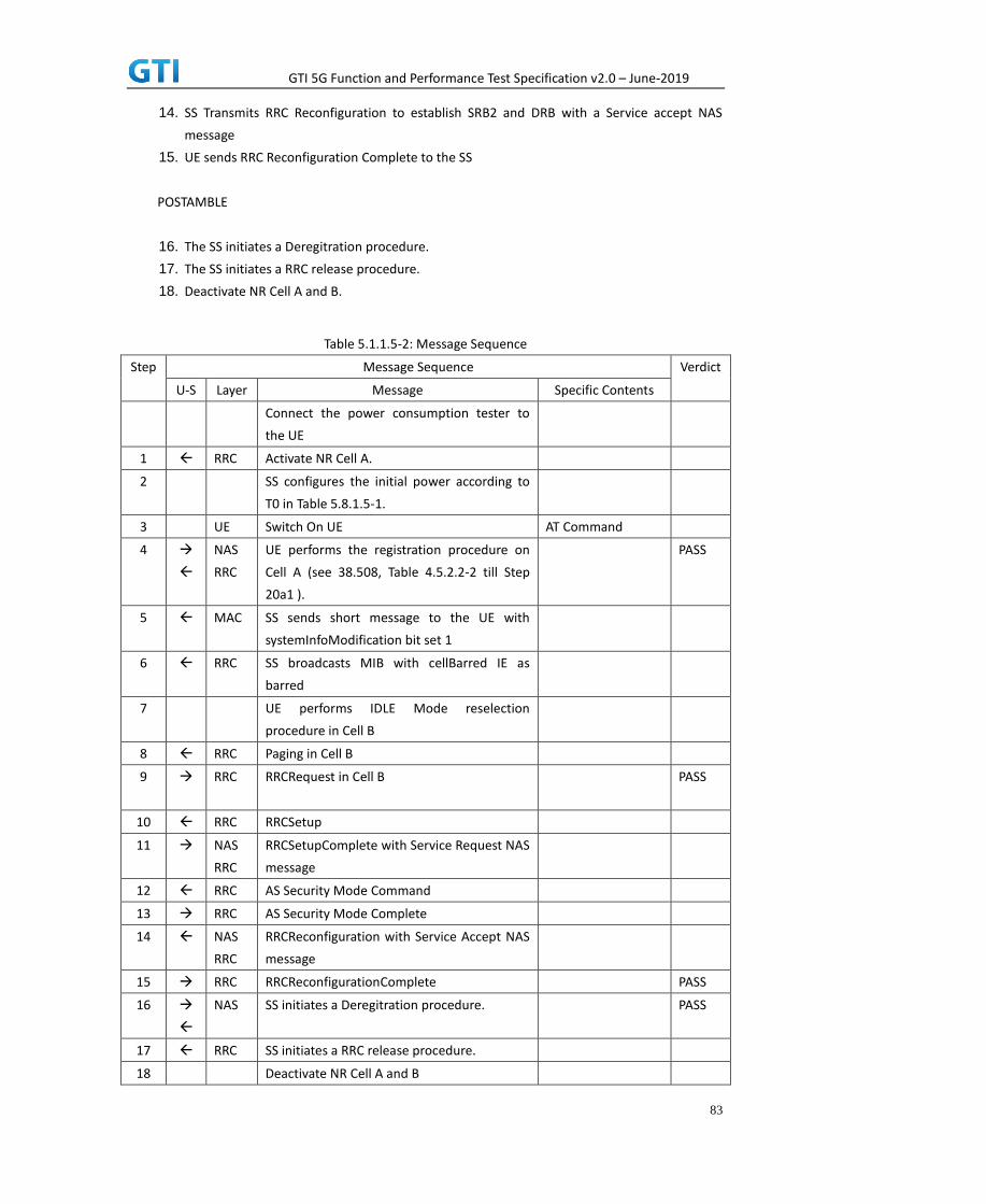
GTI 5G Function and Performance Test Specification v2.0 – June-2019
83
14. SS Transmits RRC Reconfiguration to establish SRB2 and DRB with a Service accept NAS
message
15. UE sends RRC Reconfiguration Complete to the SS
POSTAMBLE
16. The SS initiates a Deregitration procedure.
17. The SS initiates a RRC release procedure.
18. Deactivate NR Cell A and B.
Table 5.1.1.5-2: Message Sequence
Step Message Sequence Verdict
U-S Layer Message Specific Contents
Connect the power consumption tester to
the UE
1 RRC Activate NR Cell A.
2 SS configures the initial power according to
T0 in Table 5.8.1.5-1.
3 UE Switch On UE AT Command
4
NAS
RRC
UE performs the registration procedure on
Cell A (see 38.508, Table 4.5.2.2-2 till Step
20a1 ).
PASS
5 MAC SS sends short message to the UE with
systemInfoModification bit set 1
6 RRC SS broadcasts MIB with cellBarred IE as
barred
7 UE performs IDLE Mode reselection
procedure in Cell B
8 RRC Paging in Cell B
9
RRC RRCRequest in Cell B PASS
10 RRC RRCSetup
11 NAS
RRC
RRCSetupComplete with Service Request NAS
message
12 RRC AS Security Mode Command
13 RRC AS Security Mode Complete
14 NAS
RRC
RRCReconfiguration with Service Accept NAS
message
15 RRC RRCReconfigurationComplete PASS
16
NAS SS initiates a Deregitration procedure. PASS
17 RRC SS initiates a RRC release procedure.
18 Deactivate NR Cell A and B
GTI 5G Function and Performance Test Specification v2.0 – June-2019
84
5.8.1.6 Expected Result
While UE is RRC IDLE mode if Cell is barred verify that UE is reselecting into neighbour cell.
5.8.2 Access Categories for Different Services
5.8.2.1 Test Purpose
This case is to verify when different services are initiated then different access category is requested
by the device
5.8.2.2 Reference specification
TS 38.304, TS 38.331, TS 38.300
5.8.2.3 Applicability
This test applies to the device that supports SA or SA+NSA.
5.8.2.4 Test conditions
[SS configuration]
Cell A is a NR Cell.
Cell A supports only SA
NR Cell A
Cell Id=01 TAC = 01
MCC = 460 MNC = 00
NR Band = n41
NR-ARFCN= f1
Bandwidth = 100 MHz
SS/PBCH SSS EPRE = -125 dBm/30kHz
[UE configuration]
The test UICC with USIM should be inserted
The UE is in AUTOMATIC network selection mode.
UE works in SA mode.
[Initial conditions]
SS
NR Cell A is not active

GTI 5G Function and Performance Test Specification v2.0 – June-2019
85
The test shall be performed under ideal radio conditions.
UE
UE is powered off
5.8.2.5 Test procedure
Table 5.1.1.5-1: Time of cell power level and parameter changes
Time NR
Cell A
Remark
T0 -75
PREAMBLE
1. Activate NR Cell A.The SS configures the corresponding Master Information Block and System
Information Block broadcast.
2. The SS configures the initial power according to T0 in Table 5.8.2.5-1.
3. The UE is powered ON.
4. The UE performs the registration procedure on Cell A (see 38.508, Table 4.5.2.2-2 till Step
18).
MAIN BODY
5. SS initiates paging message to UE
6. UE sends RRC Request with access category as 0(establishment cause as mt-Access) to the SS
7. SS transmits RRC Setup message to UE
8. UE sends RRC Setup Complete with Service Request NAS message
9. SS transmits the Access stratum Security Mode Command to the UE
10. UE responds with AS Security Mode Complete to the SS
11. SS Transmits RRC Reconfiguration to establish SRB2 and DRB with a Service accept NAS
message
12. UE sends RRC Reconfiguration Complete to the SS
13. RRC connection is released by SS
14. Start the ping from UE to SS
15. UE sends RRC Request with access category as 7(establishment cause as mo-Data) to the SS
16. SS transmits RRC Setup message to UE
17. UE sends RRC Setup Complete to SS
18. SS transmits the AS Security Mode Command to the UE
19. UE responds with AS Security Mode Complete to the SS
20. SS Transmits RRC Reconfiguration to establish SRB2 and DRB with a Service accept NAS
message
21. UE sends RRC Reconfiguration Complete to the SS
22. Ping is performed
23. RRC connection is released by SS
24. Initiate the switch off procedure from UE

GTI 5G Function and Performance Test Specification v2.0 – June-2019
86
25. UE sends RRC Request with access category as 3(establishment cause as mo-signaling) to the
SS
26. SS transmits RRC Setup message to UE
27. UE sends RRC Setup Complete with Deregistration NAS message
28. SS Transmits Deregistration Accept to UE
POSTAMBLE
29. The SS initiates a RRC release procedure.
30. Deactivate NR Cell A.
Table 5.1.1.5-2: Message Sequence
Step Message Sequence Verdict
U-S Layer Message Specific Contents
Connect the power consumption tester to
the UE
1 RRC Activate NR Cell A.
2 SS configures the initial power according to
T0 in Table 5.8.2.5-1.
3 UE Switch On UE AT Command
4
NAS
RRC
UE performs the registration procedure on
Cell A (see 38.508, Table 4.5.2.2-2 till Step
20a1 ).
PASS
5 RRC Paging
6 RRC RRCRequest with establishment cause as
mt-Access
PASS
7 RRC RRCSetup
8 NAS
RRC
RRCSetupComplete with Service Request NAS
message
9 RRC AS Security Mode Command
10 RRC AS Security Mode Complete
11 NAS
RRC
RRCReconfiguration with Service Accept NAS
message
12 RRC RRCReconfigurationComplete PASS
13 RRC RRCRelease
14 Start the ping from UE to SS
15 RRC RRCRequest with establishment cause as
mo-Data
PASS
16 RRC RRCSetup
17 NAS
RRC
RRCSetupComplete
18 RRC AS Security Mode Command

GTI 5G Function and Performance Test Specification v2.0 – June-2019
87
19 RRC AS Security Mode Complete
20 NAS
RRC
RRCReconfiguration
21 RRC RRCReconfigurationComplete PASS
22 PING Request and Response
23 RRC RRCRelease
24 Initiate the switch off Procedure from UE
25 RRC RRCRequest with establishment cause as
mo-Signaling
PASS
26 RRC RRCSetup
27 RRC
NAS
RRCSetupComplete with Deregistration
Request
PASS
28 NAS Deregistration Accept
29 RRC SS initiates a RRC release procedure.
30 Deactivate NR Cell A
5.8.2.6 Expected Result
For Different services, UE should use different access categories.
5.8.3 Access Barring Check in RRC
5.8.3.1 Test Purpose
This case is to verify access is barred for certain services verify that UE is not initiating access request
for those barred services
5.8.3.2 Reference specification
TS 38.304, TS 38.331, TS 38.300, TS 24.501
5.8.3.3 Applicability
This test applies to the device that supports SA or SA+NSA.
5.8.3.4 Test conditions
[SS configuration]
Cell A is a NR Cell.
Cell A supports only SA
NR Cell A
Cell Id=01 TAC = 01

GTI 5G Function and Performance Test Specification v2.0 – June-2019
88
MCC = 460 MNC = 00
NR Band = n41
NR-ARFCN= f1
Bandwidth = 100 MHz
SS/PBCH SSS EPRE = -125 dBm/30kHz
uac-BarringForCommon in SIB1 = for access category 7
[UE configuration]
The test UICC with USIM should be inserted
The UE is in AUTOMATIC network selection mode.
UE works in SA mode.
[Initial conditions]
SS
NR Cell A is not active
The test shall be performed under ideal radio conditions.
UE
UE is powered off
5.8.3.5 Test procedure
Table 5.1.1.5-1: Time of cell power level and parameter changes
Time NR
Cell A
Remark
T0 -75
PREAMBLE
1. Activate NR Cell A.The SS configures the corresponding Master Information Block and System
Information Block broadcast.
2. The SS configures the initial power according to T0 in Table 5.8.3.5-1.
3. The UE is powered ON.
4. The UE performs the registration procedure on Cell A (see 38.508, Table 4.5.2.2-2 till Step
18).
MAIN BODY
5. Start the ping from UE to SS
6. Verify that UE is not sending any RRCRequest for access attempt
7. SS initiates paging message to UE
8. UE sends RRC Request with access category as 0(establishment cause as mt-Access) to the SS
9. SS transmits RRC Setup message to UE
10. UE sends RRC Setup Complete with Service Request NAS message

GTI 5G Function and Performance Test Specification v2.0 – June-2019
89
11. SS transmits the Access stratum Security Mode Command to the UE
12. UE responds with AS Security Mode Complete to the SS
13. SS Transmits RRC Reconfiguration to establish SRB2 and DRB with a Service accept NAS
message
14. UE sends RRC Reconfiguration Complete to the SS
POSTAMBLE
15. The SS initiates a Deregitration procedure.
16. The SS initiates a RRC release procedure.
17. Deactivate NR Cell A.
Table 5.1.1.5-2: Message Sequence
Step Message Sequence Verdict
U-S Layer Message Specific Contents
Connect the power consumption tester to
the UE
1 RRC Activate NR Cell A.
2 SS configures the initial power according to
T0 in Table 5.8.3.5-1.
3 UE Switch On UE AT Command
4
NAS
RRC
UE performs the registration procedure on
Cell A (see 38.508, Table 4.5.2.2-2 till Step
20a1 ).
PASS
5 Start the ping from UE to SS
6 Verify that UE is not sending RRCRequest for
access attempt
PASS
7 RRC Paging
8 RRC RRCRequest with establishment cause as
mt-Access
PASS
9 RRC RRCSetup
10 NAS
RRC
RRCSetupComplete with Service Request NAS
message
11 RRC AS Security Mode Command
12 RRC AS Security Mode Complete
13 NAS
RRC
RRCReconfiguration with Service Accept NAS
message
14 RRC RRCReconfigurationComplete PASS
15
NAS SS initiates a Deregitration procedure. PASS
16 RRC SS initiates a RRC release procedure.
17 Deactivate NR Cell A.

GTI 5G Function and Performance Test Specification v2.0 – June-2019
90
5.8.3.6 Expected Result
If access category is barred by the cell, UE should not attempt to access for particular access category
6 Mobility
6.1 Intra-system (NR) Mobility
6.1.1 Intra-system cell reselection
6.1.1.1 Cell Reselection and Random Access Procedure
6.1.1.1.1 Test Purpose
When UE camps on one NR cell, based on cell selection criteria, UE correctly reselects and camp
on intra-freq/inter-freq/inter-band cell, and Verify the UE will correctly choose PRACH PREAMBLE.
6.1.1.1.2 Reference specification
3GPP TS 38.304 subclause 5.2.4
3GPP TS 38.211 subclause 6.3.3
3GPP TS 24.501 subclause 5.5
6.1.1.1.3 Applicability
This test applies to type 1 and 2 devices as described in clause 4.2.
6.1.1.1.4 Test conditions
[SS configuration]
Cell A and Cell B are intra-freq cells
Cell A and Cell C are inter-freq cells.
Cell A and Cell D are inter-band cells.
NR Cell A
Cell Id=1 TAC = 1
MCC = 460 MNC = 00
NR-ARFCN= f4
SS/PBCH SSS EPRE = -85 dBm/30kHz
PRACH Configuration Index = 0(Preamble format 0)
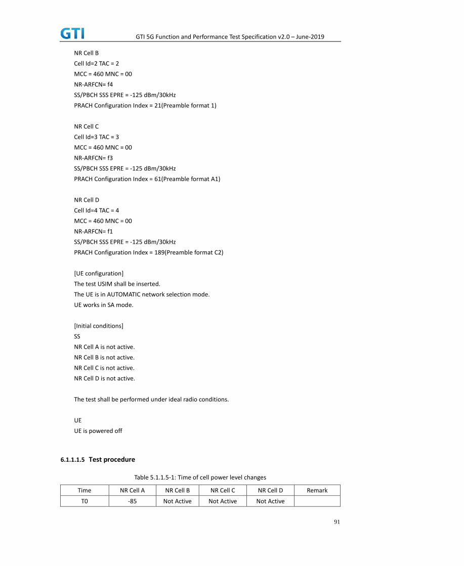
GTI 5G Function and Performance Test Specification v2.0 – June-2019
91
NR Cell B
Cell Id=2 TAC = 2
MCC = 460 MNC = 00
NR-ARFCN= f4
SS/PBCH SSS EPRE = -125 dBm/30kHz
PRACH Configuration Index = 21(Preamble format 1)
NR Cell C
Cell Id=3 TAC = 3
MCC = 460 MNC = 00
NR-ARFCN= f3
SS/PBCH SSS EPRE = -125 dBm/30kHz
PRACH Configuration Index = 61(Preamble format A1)
NR Cell D
Cell Id=4 TAC = 4
MCC = 460 MNC = 00
NR-ARFCN= f1
SS/PBCH SSS EPRE = -125 dBm/30kHz
PRACH Configuration Index = 189(Preamble format C2)
[UE configuration]
The test USIM shall be inserted.
The UE is in AUTOMATIC network selection mode.
UE works in SA mode.
[Initial conditions]
SS
NR Cell A is not active.
NR Cell B is not active.
NR Cell C is not active.
NR Cell D is not active.
The test shall be performed under ideal radio conditions.
UE
UE is powered off
6.1.1.1.5 Test procedure
Table 5.1.1.5-1: Time of cell power level changes
Time NR Cell A NR Cell B NR Cell C NR Cell D Remark
T0 -85 Not Active Not Active Not Active

GTI 5G Function and Performance Test Specification v2.0 – June-2019
92
T1 -91 -85 Not Active Not Active
T2 Not Active -91 -85 Not Active
T3 Not Active Not Active -91 -85
T4 -85 Not Active Not Active -91
PREAMBLE
1. Activate NR Cell A, NR Cell B, NR Cell C and NR Cell D.The SS configures the transmission of
the Master Information Block and starts the System Information Block broadcasting on all
cells.
2. The SS configures the initial power according to T0 in Table 6.1.1.1.5-1.
3. The UE is powered ON.
4. UE performs the registration procedure on Cell A according to subclause 5.4.1 step3-18.
5. The RRC connection is released by the SS.
MAIN BODY
6. The SS changes the cell power according to T1 in table 6.1.1.1.5-1.
7. The UE performs the registration procedure for mobility on Cell B.
8. The RRC connection is released by the SS. The UE enters Idle Mode.
9. The SS changes the cell power according to T2 in table 6.1.1.1.5-1.
10. The UE performs the registration procedure for mobility on Cell C.
11. The RRC connection is released by the SS. The UE enters Idle Mode.
12. The SS changes the cell power according to T3 in table 6.1.1.1.5-1.
13. UE performs the registration procedure for mobility on Cell D.
14. The RRC connection is released by the SS. The UE enters Idle Mode.
15. The SS changes the cell power according to T4 in table 6.1.1.1.5-1.
16. UE performs the registration procedure for mobility on Cell A.
POSTAMBLE
17. The SS initiates a de-registration procedure.
18. The SS initiates a RRC release procedure.
19. Deactivate NR Cell A, NR Cell B, NR Cell C and NR Cell D.
Table 5.1.1.5-2: Message Sequence
Step Message Sequence Verdict
U-S Layer Message Specific Contents
1 RRC Activate NR Cell A, NR Cell B, NR Cell C, NR
Cell D
2 Configure the initial power according to T0 in
Table 6.1.1.1.5-1.
3 UE Switch On UE AT Command
4
NAS
RRC
UE performs the registration procedure on
Cell A according to subclause 5.4.1 step3-18
PASS
5 RRC The RRC connection is released by the SS.

GTI 5G Function and Performance Test Specification v2.0 – June-2019
93
6 The SS changes the cell power according to
T1 in table 6.1.1.1.5-1.
7
NAS
RRC
UE performs the registration procedure for
mobility on Cell B
PASS
8 RRC The RRC connection is released by the SS.
The UE enters Idle Mode
9 SS changes the cell power according to T2 in
table 6.1.1.1.5-1.
10
NAS
RRC
UE performs the registration procedure for
mobility on Cell C.
PASS
11 RRC The RRC connection is released by the SS.
The UE enters Idle Mode.
12 The SS changes the cell power according to
T3 in table 6.1.1.1.5-1.
13
NAS
RRC
UE performs the registration procedure for
mobility on Cell D.
PASS
14 RRC The RRC connection is released by the SS.
The UE enters Idle Mode.
15 The SS changes the cell power according to
T4 in table 6.1.1.1.5-1.
16
NAS
RRC
UE performs the registration procedure for
mobility on Cell A.
PASS
17
NAS SS initiates a de-registration procedure. PASS
18 RRC The SS initiates a RRC release procedure..
19 Deactivate NR Cell A, NR Cell B, NR Cell C, NR
Cell D
6.1.1.1.6 Expected Result
Verify the UE correctly reselect and camp on a serving cell with different preamble format.
6.1.2 Intra-system handover
6.1.2.1 Intra-freq HO with IP data transfer
6.1.2.1.1 Test Purpose
Execute handovers between two NR Intra-frequency neighbour cells with IP data transfer.
1), Perform non-contention based random access procedure and lossless handover.
2), Perform Contention based random access procedure and lossless handover.
Verify the UE is able to maintain the service.
6.1.2.1.2 Reference specification
3GPP TS 38.331 subclause 5.3.5 and 5.5

GTI 5G Function and Performance Test Specification v2.0 – June-2019
94
6.1.2.1.3 Applicability
This test applies to type 1 and 2 devices as described in clause 4.2.
6.1.2.1.4 Test conditions
[SS configuration]
Cell A and Cell B are intra-freq NR cells.
NR Cell A
Cell Id=1 TAC = 1
MCC = 460 MNC = 00
NR-ARFCN= f1
SS/PBCH SSS EPRE = -85 dBm/30kHz
NR Cell B
Cell Id=2 TAC = 1
MCC = 460 MNC = 00
NR-ARFCN= f1
SS/PBCH SSS EPRE = -125 dBm/30kHz
[UE configuration]
The test USIM shall be inserted.
The UE is in AUTOMATIC network selection mode.
UE works in SA mode.
[Initial conditions]
SS
NR Cell A is not active.
NR Cell B is not active.
The test shall be performed under ideal radio conditions.
UE
UE is powered off .
6.1.2.1.5 Test procedure
Table 5.1.1.5-1: Time of cell power level and parameter changes
Time NR Cell A NR Cell B Remark
T0 -85 Not Active
T1 -91 -85
T2 -85 -91
PREAMBLE
1. Activate NR Cell A and NR Cell B.The SS configures the transmission of the Master

GTI 5G Function and Performance Test Specification v2.0 – June-2019
95
Information Block and starts the System Information Block broadcasting on all cells.
2. The SS configures the initial power according to T0 in Table 6.1.2.1.5-1.
3. The UE is powered ON.
MAIN BODY
4. The UE performs Registration procedure on NR Cell A according to subclause 5.4.1 step3-18.
A3 measurement is configured in RRC CONNECTION RECONFIGURATION message.
5. Verify the data transmission is performed successfully on Cell A.
6. The SS changes the cell power according to T1 in table 6.1.2.1.5-1.
7. The UE performs measurements on the neighbor Cell B and provides measurement reports
(Event A3) to the SS.
8. The SS initiates a handover to Cell B by sending a RRC CONNECTION RECONFIGURATION
message. The RRC CONNECTION RECONFIGURATION message contains CFRA in
RACH-ConfigDedicated in order to trigger non-contention based random access to the target
cell. A3 measurement is configured in RRC CONNECTION RECONFIGURATION message. Cell B
becomes the serving cell and Cell A becomes the new neighbor cell.
9. The UE completes the HO procedure by sending the RRC CONNECTION RECONFIGURATION
COMPLETE message and proceeding CFRA procedure on target Cell B.
10. Verify the data transmission is continued on Cell B.
11. The SS changes the cell power according to T2 in table 6.1.2.1.5-1.
12. The UE performs measurements on the neighbor Cell A and provides measurement reports
(Event A3) to the SS.
13. The SS initiates a handover to Cell A by sending a RRC CONNECTION RECONFIGURATION
message. The RRC CONNECTION RECONFIGURATION message does not contain CFRA in
RACH-ConfigDedicated in order to trigger contention based random access to the target cell.
Cell A becomes the serving cell and Cell B becomes the new neighbor cell.
14. The UE completes the HO procedure by sending the RRC CONNECTION RECONFIGURATION
COMPLETE message and proceeding CBRA procedure on target Cell A.
15. Verify the data transmission is continued on Cell A.
POSTAMBLE
16. SS initiates a de-registration procedure.
17. The SS initiates a RRC release procedure.
18. Deactivate NR Cell A and NR Cell B.
Table 5.1.1.5-2: Message Sequence
Step Message Sequence Verdict
U-S Layer Message Specific Contents
1 RRC SS Activates NR Cell A and NR Cell B
2 SS configures the initial power according to T0 in
Table 6.1.2.1.5-1.
3 UE Switch On UE AT Command
4
NAS
RRC
UE performs Registration procedure on NR Cell
A according to subclause 5.4.1 step3-18. A3
PASS

GTI 5G Function and Performance Test Specification v2.0 – June-2019
96
measurement is configured in RRC CONNECTION
RECONFIGURATION message.
5 Verify the data transmission is performed
successfully on Cell A.
PASS
6 SS changes the cell power according to T1 in
table 6.1.2.1.5-1.
7 RRC UE performs measurements on the neighbor
Cell B and provides measurement reports (Event
A3) to the SS.
PASS
8 RRC SS initiates a handover by sending RRC
CONNECTION RECONFIGURATION message.
9 RRC UE sends the RRC CONNECTION
RECONFIGURATION COMPLETE message and
success CFRA procedure on target Cell B.
PASS
10 Verify the data transmission is continued on Cell
B.
PASS
11 SS changes the cell power according to T2 in
table 6.1.2.1.5-1.
12 RRC UE performs measurements on the neighbor
Cell A and provides measurement reports (Event
A3) to the SS.
PASS
13
RRC SS SS initiates a handover by sending RRC
CONNECTION RECONFIGURATION message.
14 RRC UE sends the RRC CONNECTION
RECONFIGURATION COMPLETE message and
success CBRA procedure on target Cell A.
PASS
15 Verify the data transmission is continued on Cell
A.
PASS
16
NAS SS initiates a de-registration procedure. PASS
17 RRC SS initiates a RRC release procedure.
18 Deactivate NR Cell A and NR Cell B.
6.1.2.1.6 Expected Result
Verify the UE can perform the handover procedure with non-contention based random access
procedure successfully.
Verify the UE can perform the handover procedure with contention based random access
procedure successfully.
6.1.2.2 Inter-freq HO with IP data transfer
6.1.2.2.1 Test Purpose
Execute handovers between NR Inter-frequency neighbour cells with IP data transfer.

GTI 5G Function and Performance Test Specification v2.0 – June-2019
97
1) Perform non-contention based random access procedure and lossless handover.
2) Perform Contention based random access procedure and lossless handover.
Verify that the UE supports handover between cells with different bandwidth and is able to
maintain the service.
6.1.2.2.2 Reference specification
3GPP TS 38.331 subclause 5.3.5 and 5.5
6.1.2.2.3 Applicability
This test applies to type 1 and 2 devices as described in clause 4.2.
6.1.2.2.4 Test conditions
[SS configuration]
Cell A and Cell B are inter-freq NR cells
NR Cell A
Cell Id=1 TAC = 1
MCC = 460 MNC = 00
Frequency Configuration = f1
SS/PBCH SSS EPRE = -125 dBm/30kHz
NR Cell B
Cell Id=2 TAC = 1
MCC = 460 MNC = 00
Frequency Configuration = f2
SS/PBCH SSS EPRE = -125 dBm/30kHz
NR Cell C
Cell Id=3 TAC = 1
MCC = 460 MNC = 00
Frequency Configuration = f3
SS/PBCH SSS EPRE = -125 dBm/30kHz
[UE configuration]
The test USIM shall be inserted.
The UE is in AUTOMATIC network selection mode.
UE works in SA mode.
[Initial conditions]
SS
NR Cell A is not active.
NR Cell B is not active.
The test shall be performed under ideal radio conditions.

GTI 5G Function and Performance Test Specification v2.0 – June-2019
98
UE
UE is powered off.
6.1.2.2.5 Test procedure
Table 6.1.2.2.5-1: Time of cell power level and parameter changes
Time Parameter Unit NR Cell A NR Cell B NR Cell C Remark
T0
SS/PBCH,
SSS EPRE dBm/SCS
-85 Not Active Not Active
T1 -97 -85 Not Active
T2 -85 -97 Not Active
T3 -97 -97 -85
PREAMBLE
1. Activate NR Cell A. The SS configures the transmission of the Master Information Block and
starts the System Information Block broadcasting on all cells.
2. The SS configures the initial power according to T0 in Table 6.1.2.2.5-1.
3. The UE is powered ON.
MAIN BODY
4. The UE performs Registration procedure on NR Cell A according to subclause 5.4.1 step3-18.
A4 measurement is configured in RRC CONNECTION RECONFIGURATION message.
5. Verify the data transmission is performed successfully on Cell A.
6. Activate NR Cell B. The SS changes the cell power according to T1 in table 6.1.2.2.5-1.
7. The UE performs measurements on the neighbor Cell B and provides measurement reports
(Event A4) to the SS.
8. The SS initiates a handover to Cell B by sending a RRC CONNECTION RECONFIGURATION
message. The RRC CONNECTION RECONFIGURATION message contains CFRA in
RACH-ConfigDedicated in order to trigger non-contention based random access to the target
cell. Cell B becomes the serving cell and Cell A becomes the new neighbor cell. A4
measurement is configured in RRC CONNECTION RECONFIGURATION message.
9. The UE completes the HO procedure by sending the RRC CONNECTION RECONFIGURATION
COMPLETE message and proceeding CFRA procedure on target Cell B.
10. Verify the data transmission is continued on Cell B.
11. The SS changes the cell power according to T2 in table 6.1.2.2.5-1.
12. The UE performs measurements on the neighbor Cell A and provides measurement reports
(Event A4) to the SS.
13. The SS initiates a handover to Cell A by sending a RRC CONNECTION RECONFIGURATION
message. The RRC CONNECTION RECONFIGURATION message does not contain CFRA in
RACH-ConfigDedicated in order to trigger contention based random access to the target cell.
Cell A becomes the serving cell and Cell B becomes the new neighbor cell.
14. The UE completes the HO procedure by sending the RRC CONNECTION RECONFIGURATION
COMPLETE message and proceeding CBRA procedure on target Cell A.
15. Verify the data transmission is continued on Cell A.
16. Activate NR Cell C. The SS changes the cell power according to T3 in table 6.1.2.2.5-1.

GTI 5G Function and Performance Test Specification v2.0 – June-2019
99
17. The UE performs measurements on the neighbor Cell C and provides measurement reports
(Event A4) to the SS.
18. The SS initiates a handover to Cell C by sending a RRC CONNECTION RECONFIGURATION
message. Cell C becomes the serving cell and Cell A becomes the new neighbor cell. A4
measurement is configured in RRC CONNECTION RECONFIGURATION message.
19. The UE completes the HO procedure by sending the RRC CONNECTION RECONFIGURATION
COMPLETE message and proceeding CFRA procedure on target Cell C.
20. Verify the data transmission is continued on Cell C.
POSTAMBLE
21. The SS initiates a de-registration procedure.
22. The SS initiates a RRC release procedure.
23. Deactivate NR Cell A and NR Cell B.
Table 6.1.2.2.5-2: Message Sequence
Step Message Sequence Verdict
U-S Layer Message Specific Contents
1 RRC SS Activates NR Cell A and NR Cell B
2 SS configures the initial power according to T0 in
Table 6.1.2.2.5-1.
3 UE Switch On UE AT Command
4
NAS
RRC
UE performs Registration procedure on NR Cell
A according to subclause 5.4.1 step3-18. A4
measurement is configured in RRC CONNECTION
RECONFIGURATION message.
PASS
5 Data transmission is performed successfully on
Cell A.
PASS
6 SS changes the cell power according to T1 in
table 6.1.2.2.5-1.
7 RRC UE performs measurements on the neighbor
Cell B and provides measurement reports (Event
A4) to the SS.
PASS
8 RRC SS initiates a handover by sending RRC
CONNECTION RECONFIGURATION message.
9 RRC UE sends the RRC CONNECTION
RECONFIGURATION COMPLETE message and
success CFRA procedure on target Cell B.
PASS
10 Data transmission is continued on Cell B. PASS
11 SS changes the cell power according to T2 in
table 6.1.2.2.5-1.
12 RRC UE performs measurements on the neighbor
Cell A and provides measurement reports (Event
A4) to the SS.
PASS

GTI 5G Function and Performance Test Specification v2.0 – June-2019
100
13
RRC SS SS initiates a handover by sending RRC
CONNECTION RECONFIGURATION message.
14 RRC UE sends the RRC CONNECTION
RECONFIGURATION COMPLETE message and
success CBRA procedure on target Cell A.
PASS
15 Data transmission is continued on Cell A. PASS
16 Activate NR Cell C. The SS changes the cell
power according to T3 in table 6.1.2.2.5-1.
17 The UE performs measurements on the
neighbor Cell C and provides measurement
reports (Event A4) to the SS.
18 RRC CONNECTION RECONFIGURATION message.
A4 measurement is configured in RRC
CONNECTION RECONFIGURATION .
19 RRC RRC CONNECTION RECONFIGURATION
COMPLETE message and proceeding CFRA
procedure on target Cell C.
20 Data transmission is continued on Cell C PASS
21
NAS SS initiates a de-registration procedure. PASS
22 RRC SS initiates a RRC release procedure.
23 Deactivate NR Cell A and NR Cell B.
6.1.2.2.6 Expected Result
Verify the UE can perform the handover procedure with non-contention based random access
procedure successfully.
Verify the UE can perform the handover procedure with contention based random access
procedure successfully.
6.1.2.3 Inter-Freq. HO Failure, RRC Connection Reestablish to a Prepared Inter-Freq cell
6.1.2.3.1 Test Purpose
DRB Setup with a Real Service Ongoing, Two Inter-frequency cells are prepared for handover.
Handover to the target cell is failed. A successful RRC reestablish to a prepared Inter-frequency cell is
performed. The test scenario is performed several times. Verify the UE is able to maintain the service.
6.1.2.3.2 Reference specification
3GPP TS 38.331 subclause 5.3.5, 5.3.7 and 5.5
6.1.2.3.3 Applicability
This test applies to type 1 and 2 devices as described in clause 4.2.
6.1.2.3.4 Test conditions

GTI 5G Function and Performance Test Specification v2.0 – June-2019
101
[SS configuration]
Cell A , Cell B and Cell C are NR inter-freq cells.
NR Cell A
Cell Id=1 TAC = 1
MCC = 460 MNC = 00
NR-ARFCN= f1
SS/PBCH SSS EPRE = -85 dBm/30kHz(adjust according to Table 5.1.1.5-1)
NR Cell B
Cell Id=2 TAC = 1
MCC = 460 MNC = 00
NR-ARFCN= f2
SS/PBCH SSS EPRE = -125 dBm/30kHz(adjust according to Table 5.1.1.5-1)
NR Cell C
Cell Id=3 TAC = 1
MCC = 460 MNC = 00
NR-ARFCN= f1
SS/PBCH SSS EPRE = -125 dBm/30kHz(adjust according to Table 5.1.1.5-1)
[UE configuration]
The test USIM shall be inserted.
The UE is in AUTOMATIC network selection mode.
UE works in SA mode.
[Initial conditions]
SS
NR Cell A is not active.
NR Cell B is not active.
NR Cell C is not active.
The test shall be performed under ideal radio conditions.
UE
UE is powered off
6.1.2.3.5 Test procedure
Table 5.1.1.5-1: Time of cell power level and parameter changes
Time Cell A Cell B Cell C Remark
T0 -85 Not Active Not Active
T1 -97 -85 Not Active
T2 -97 Not Active -85

GTI 5G Function and Performance Test Specification v2.0 – June-2019
102
T3 Not Active -85 -97
T4 -85 Not Active -97
PREAMBLE
1. Activate NR Cell A, NR Cell B and NR Cell C.The SS configures the transmission of the Master
Information Block and starts the System Information Block broadcasting on all cells.
2. The SS configures the initial power according to T0 in Table 6.1.2.3.5-1.
3. The UE is powered ON.
MAIN BODY
4. The UE performs Registration procedure on NR Cell A according to subclause 5.4.1 step3-18.
5. Verify the data transmission is performed successfully on Cell A.
6. The SS sends RRC Connection Reconfiguration message to setup inter-freq measurement
(Event A4).
7. The UE sends RRC Connection Reconfiguration Complete message.
8. The SS changes the cell power according to T1 in table 6.1.2.3.5-1.
9. The UE performs measurements on the neighbor Cell B and provides measurement reports
(Event A4) to the SS.
10. The SS changes the cell power according to T2 in table 6.1.2.3.5-1.
11. The SS sends an RRC Connection Reconfiguration message to order the UE to perform
inter-freq handover from Cell A to Cell B.
12. The UE fails to perform the Handover as Cell B is not available.
13. The UE performs RRC Connection Reestablishment procedure on Cell C.
14. Verify the data transmission is continued after the connection reestablishment on Cell C.
15. The SS sends RRC Connection Reconfiguration message to setup inter-freq measurement
(Event A4).
16. The UE sends RRC Connection Reconfiguration Complete message.
17. The SS changes the cell power according to T3 in table 6.1.2.3.5-1.
18. The UE performs measurements on the neighbor Cell B and provides measurement reports
(Event A4) to the SS.
19. The SS changes the cell power according to T4 in table 6.1.2.3.5-1.
20. The SS sends an RRC Connection Reconfiguration message to order the UE to perform
inter-freq handover from Cell C to Cell B.
21. The UE fails to perform the Handover as Cell B is not available.
22. The UE performs RRC Connection Reestablishment procedure on Cell A.
23. Verify the data transmission is continued after the connection reestablishment on Cell A.
24. Repeat steps 6 to 23 four times.
POSTAMBLE
25. The SS initiates a de-registration procedure.
26. The SS initiates a RRC release procedure.
27. Deactivate NR Cell A, NR Cell B and NR Cell C.
Table 5.1.1.5-2: Message Sequence

GTI 5G Function and Performance Test Specification v2.0 – June-2019
103
Step Message Sequence Verdict
U-S Layer Message Specific Contents
1 RRC Activate NR Cell A, NR Cell B and NR Cell C
2 The SS configures the initial power according
to T0 in Table 6.1.2.3.5-1.
3 UE Switch On UE AT Command
4
NAS
RRC
UE performs Registration procedure on NR
Cell A according to subclause 5.4.1 step3-18.
PASS
5 Verify the data transmission is performed
successfully on Cell A.
PASS
6 RRC SS sends RRC Connection Reconfiguration
message to setup inter-freq measurement
(Event A4).
7 RRC UE sends RRC Connection Reconfiguration
Complete message.
PASS
8 SS changes the cell power according to T1 in
table 6.1.2.3.5-1
9 RRC UE performs measurements on the neighbor
Cell B and provides measurement reports
(Event A4) to the SS.
PASS
10 SS changes the cell power according to T2 in
table 6.1.2.3.5-1.
11 RRC SS sends an RRC Connection Reconfiguration
message to order the UE to perform
inter-freq handover from Cell A to Cell B.
12 UE fails to perform the Handover as Cell B is
not available.
13
RRC UE performs RRC Connection
Reestablishment procedure on Cell C.
PASS
14 Verify the data transmission is continued
after the connection reestablishment on Cell
C.
PASS
15 RRC SS sends RRC Connection Reconfiguration
message to setup inter-freq measurement
(Event A4
16 RRC UE sends RRC Connection Reconfiguration
Complete message
PASS
17 SS changes the cell power according to T3 in
table 6.1.2.3.5-1.
18 RRC UE performs measurements on the neighbor
Cell B and provides measurement reports
(Event A4) to the SS
PASS
19 SS changes the cell power according to T4 in
table 6.1.2.3.5-1.

GTI 5G Function and Performance Test Specification v2.0 – June-2019
104
20 RRC SS sends an RRC Connection Reconfiguration
message to order the UE to perform
inter-freq handover from Cell C to Cell B.
21 UE fails to perform the Handover as Cell B is
not available.
22
RRC UE performs RRC Connection
Reestablishment procedure on Cell A.
PASS
23 Verify the data transmission is continued
after the connection reestablishment on Cell
A.
PASS
24 Repeat steps 6 to 23 four times.
25
NAS SS initiates a de-registration procedure. PASS
26 RRC The SS initiates a RRC release procedure.
27 Deactivate NR Cell A, NR Cell B and NR Cell C.
6.1.2.3.6 Expected Result
Verify the UE can reestablish connection to an Inter-freq Cell after the inter-freq handover failure
successfully.
Verify the UE can maintain the data transmission after the connection reestablishment.
successfully.
6.1.2.4 Inter-band HO with IP data transfer
6.1.2.4.1 Test Purpose
Execute handovers between two NR Inter-band neighbour cells with IP data transfer.
1), Perform non-contention based random access procedure and lossless handover.
2), Perform Contention based random access procedure and lossless handover.
Verify the UE is able to maintain the service.
6.1.2.4.2 Reference specification
3GPP TS 38.331 subclause 5.3.5 and 5.5
6.1.2.4.3 Applicability
This test applies to type 1 and 2 devices as described in clause 4.2.
6.1.2.4.4 Test conditions
[SS configuration]
Cell A and Cell B are inter-band NR cells
NR Cell A
Cell Id=1 TAC = 1

GTI 5G Function and Performance Test Specification v2.0 – June-2019
105
MCC = 460 MNC = 00
NR-ARFCN= f1
SS/PBCH SSS EPRE = -125 dBm/30kHz
NR Cell B
Cell Id=2 TAC = 1
MCC = 460 MNC = 00
NR-ARFCN= f1
SS/PBCH SSS EPRE = -125 dBm/30kHz
[UE configuration]
The test USIM shall be inserted.
The UE is in AUTOMATIC network selection mode.
UE works in SA mode.
[Initial conditions]
SS
NR Cell A is not active.
NR Cell B is not active.
The test shall be performed under ideal radio conditions.
UE
UE is powered off.
6.1.2.4.5 Test procedure
Table 5.1.1.5-1: Time of cell power level and parameter changes
Time NR Cell A NR Cell B Remark
T0 -85 Not Active
T1 -97 -85
T2 -85 -97
PREAMBLE
1. Activate NR Cell A and NR Cell B.The SS configures the transmission of the Master
Information Block and starts the System Information Block broadcasting on all cells.
2. The SS configures the initial power according to T0 in Table 6.1.2.4.5-1.
3. The UE is powered ON.
MAIN BODY
4. The UE performs Registration procedure on NR Cell A according to subclause 5.4.1 step3-18.
A4 measurement is configured in RRC CONNECTION RECONFIGURATION message.
5. Verify the data transmission is performed successfully on Cell A.
6. The SS changes the cell power according to T1 in table 6.1.2.4.5-1.
7. The UE performs measurements on the neighbor Cell B and provides measurement reports
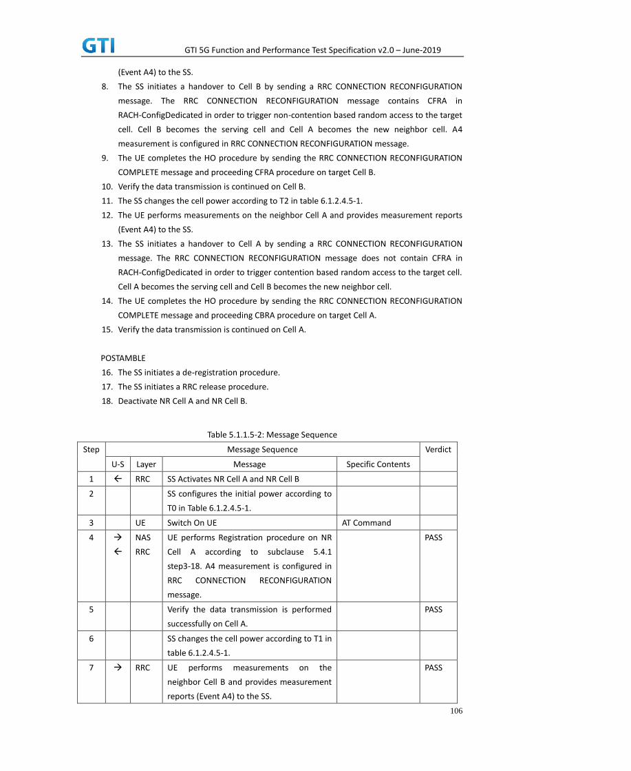
GTI 5G Function and Performance Test Specification v2.0 – June-2019
106
(Event A4) to the SS.
8. The SS initiates a handover to Cell B by sending a RRC CONNECTION RECONFIGURATION
message. The RRC CONNECTION RECONFIGURATION message contains CFRA in
RACH-ConfigDedicated in order to trigger non-contention based random access to the target
cell. Cell B becomes the serving cell and Cell A becomes the new neighbor cell. A4
measurement is configured in RRC CONNECTION RECONFIGURATION message.
9. The UE completes the HO procedure by sending the RRC CONNECTION RECONFIGURATION
COMPLETE message and proceeding CFRA procedure on target Cell B.
10. Verify the data transmission is continued on Cell B.
11. The SS changes the cell power according to T2 in table 6.1.2.4.5-1.
12. The UE performs measurements on the neighbor Cell A and provides measurement reports
(Event A4) to the SS.
13. The SS initiates a handover to Cell A by sending a RRC CONNECTION RECONFIGURATION
message. The RRC CONNECTION RECONFIGURATION message does not contain CFRA in
RACH-ConfigDedicated in order to trigger contention based random access to the target cell.
Cell A becomes the serving cell and Cell B becomes the new neighbor cell.
14. The UE completes the HO procedure by sending the RRC CONNECTION RECONFIGURATION
COMPLETE message and proceeding CBRA procedure on target Cell A.
15. Verify the data transmission is continued on Cell A.
POSTAMBLE
16. The SS initiates a de-registration procedure.
17. The SS initiates a RRC release procedure.
18. Deactivate NR Cell A and NR Cell B.
Table 5.1.1.5-2: Message Sequence
Step Message Sequence Verdict
U-S Layer Message Specific Contents
1 RRC SS Activates NR Cell A and NR Cell B
2 SS configures the initial power according to
T0 in Table 6.1.2.4.5-1.
3 UE Switch On UE AT Command
4
NAS
RRC
UE performs Registration procedure on NR
Cell A according to subclause 5.4.1
step3-18. A4 measurement is configured in
RRC CONNECTION RECONFIGURATION
message.
PASS
5 Verify the data transmission is performed
successfully on Cell A.
PASS
6 SS changes the cell power according to T1 in
table 6.1.2.4.5-1.
7 RRC UE performs measurements on the
neighbor Cell B and provides measurement
reports (Event A4) to the SS.
PASS

GTI 5G Function and Performance Test Specification v2.0 – June-2019
107
8 RRC SS initiates a handover by sending RRC
CONNECTION RECONFIGURATION message.
9 RRC UE sends the RRC CONNECTION
RECONFIGURATION COMPLETE message
and success CFRA procedure on target Cell
B.
PASS
10 Verify the data transmission is continued on
Cell B.
PASS
11 SS changes the cell power according to T2 in
table 6.1.2.4.5-1.
12 RRC UE performs measurements on the
neighbor Cell A and provides measurement
reports (Event A4) to the SS.
PASS
13
RRC SS initiates a handover by sending RRC
CONNECTION RECONFIGURATION message.
14 RRC UE sends the RRC CONNECTION
RECONFIGURATION COMPLETE message
and success CBRA procedure on target Cell
A.
PASS
15 Verify the data transmission is continued on
Cell A.
PASS
16
NAS SS initiates a de-registration procedure. PASS
17 RRC SS initiates a RRC release procedure.
18 Deactivate NR Cell A and NR Cell B.
6.1.2.4.6 Expected Result
Verify the UE can perform the handover procedure with non-contention based random access
procedure successfully.
Verify the UE can perform the handover procedure with contention based random access
procedure successfully.
6.2 Inter-RAT Mobility
6.2.1 Inter-RAT cell reselection
6.2.1.1 Cell reselection, from NR cell to E-UTRAN cell
6.2.1.1.1 Test Purpose
UE could reselect from NR cell to E-UTRAN Cell and perform TAU.
6.2.1.1.2 Reference specification

GTI 5G Function and Performance Test Specification v2.0 – June-2019
108
TS 38.304, clause 5.2.4
6.2.1.1.3 Applicability
This test applies to type 1 and 2 devices as described in clause 4.2.
6.2.1.1.4 Test conditions
[SS configuration]
Cell A is a NR cell, Cell B is an E-UTRAN cell.
NR Cell A
Cell Id=1 TAC = 1
MCC = 460 MNC = 00
NR-ARFCN= f1
SS/PBCH SSS EPRE = -125 dBm/30kHz
E-UTRAN Cell B
Cell Id=2 TAC = 2
MCC = 460 MNC = 00
EARFCN= f1
rootSequenceIndex = 0
Reference Signal EPRE = -125 dBm/15kHz
[UE configuration]
The test USIM shall be inserted.
The UE is in AUTOMATIC network selection mode.
UE works in SA mode.
[Initial conditions]
SS
NR Cell A is not active.
E-UTRAN Cell B is not active.
The test shall be performed under ideal radio conditions.
UE
UE is powered off
6.2.1.1.5 Test procedure
Table 5.1.1.5-1: Time of cell power level and parameter changes
Time NR Cell A E-UTRAN Cell B Remark
T0 -85 Not Active
T1 -97 -85

GTI 5G Function and Performance Test Specification v2.0 – June-2019
109
PREAMBLE
1. Activate NR Cell A and E-UTRAN Cell B. The SS configures the transmission of the Master
Information Block and starts the System Information Block broadcasting on all cells.
2. The SS configures the initial power according to T0 in Table 6.2.1.1.5-1.
3. The UE is powered ON.
MAIN BODY
4. The UE performs the registration procedure on Cell A according to subclause 5.4.1 step3-18.
5. Verify the data transmission is performed successfully on Cell A.
6. The RRC connection is released by the SS.
7. The SS changes the cell power according to T1 in table 6.2.1.1.5-1.
8. The UE performs TAU and EPS bearer activation in E-UTRAN Cell B.
9. Verify the data transmission is performed successfully on E-UTRAN Cell B.
POSTAMBLE
10. The SS initiates a DETACH procedure.
11. The SS initiates a RRC release procedure.
12. Deactivate NR Cell A and E-UTRAN Cell B.
Table 5.1.1.5-2: Message Sequence
Step Message Sequence Verdict
U-S Layer Message Specific Contents
1 RRC SS Activates NR Cell A and E-UTRAN Cell B
2 SS configures the initial power according to
T0 in Table 6.2.1.1.5-1.
3 UE Switch On UE AT Command
4
NAS
RRC
UE performs the registration procedure on
Cell A according to subclause 5.4.1 step3-18.
PASS
5 Verify the data transmission is performed
successfully on Cell A.
PASS
6 RRC The RRC connection is released by the SS.
7 SS changes the cell power according to T1 in
table 6.2.1.1.5-1
8
NAS
RRC
UE performs TAU and EPS bearer activation
on E-UTRAN Cell B.
PASS
9 Verify the data transmission is performed
successfully on E-UTRAN Cell B.
PASS
10
NAS SS initiates a DETACH procedure. PASS
11 RRC SS initiates a RRC release procedure.
12 Deactivate NR Cell A and E-UTRAN Cell B.
6.2.1.1.6 Expected Result

GTI 5G Function and Performance Test Specification v2.0 – June-2019
110
Verify the UE could reselect from NR cell to E-UTRAN Cell.
6.2.1.2 Cell reselection, from E-UTRAN cell to NR cell
6.2.1.2.1 Test Purpose
UE could reselect from E-UTRAN Cell to NR cell and perform registration procedure for mobolity.
6.2.1.2.2 Reference specification
TS 36.304, clause 5.2.4
6.2.1.2.3 Applicability
This test applies to type 1 and 2 devices as described in clause 4.2.
6.2.1.2.4 Test conditions
[SS configuration]
Cell A and Cell B are E-UTRAN Cells, Cell C is a NR cell.
Cell B and Cell C are neighbor cells of Cell A
E-UTRAN Cell A
Cell Id=1 TAC = 1
MCC = 460 MNC = 00
EARFCN= f1
rootSequenceIndex = 0
Reference Signal EPRE = -85 dBm/15kHz
E-UTRAN Cell B
Cell Id=2 TAC = 2
MCC = 460 MNC = 00
EARFCN= f2
rootSequenceIndex = 0
Reference Signal EPRE = -125 dBm/15kHz
NR Cell C
Cell Id=3 TAC = 3
MCC = 460 MNC = 00
NR-ARFCN= f1
SS/PBCH SSS EPRE = -125 dBm/30kHz
[UE configuration]
The test USIM shall be inserted.
The UE is in AUTOMATIC network selection mode.
UE works in SA mode.

GTI 5G Function and Performance Test Specification v2.0 – June-2019
111
[Initial conditions]
SS
E-UTRAN Cell A is not active.
E-UTRAN Cell B is not active.
NR Cell C is not active.
The test shall be performed under ideal radio conditions.
UE
UE is powered off
6.2.1.2.5 Test procedure
Table 5.1.1.5-1: Time of cell power level and parameter changes
Time E-UTRAN Cell A E-UTRAN Cell B NR Cell C Remark
T0 -85 -91 Not Active
T1 -97 -85 -85
PREAMBLE
1. Activate E-UTRAN Cell A, E-UTRAN Cell B and NR Cell C.The SS configures the corresponding
Master Information Block and System Information Block broadcast.
2. The SS configures the initial power according to T0 in Table 6.2.1.2.5-1.
3. The UE is powered ON.
MAIN BODY
4. The UE performs the registration procedure with activation of the initial default EPS bearer
on Cell A (see 36.508, 4.5.2 ).
5. Verify the data transmission is performed successfully on E-UTRAN Cell A.
6. The RRC connection is released by the SS.
7. The SS changes cell power according to T1 in table 6.2.1.2.5-1.
8. UE performs the registration procedure for mobility on NR Cell C according to subclause
5.4.1 step3-18.
9. Verify the data transmission is performed successfully on NR Cell C.
POSTAMBLE
10. The SS initiates a de-registration procedure.
11. The SS initiates a RRC release procedure.
12. Deactivate E-UTRAN Cell A, E-UTRAN Cell B and NR Cell C.
Table 5.1.1.5-2: Message Sequence
Step Message Sequence Verdict
U-S Layer Message Specific Contents
1 RRC Activate E-UTRAN Cell A, E-UTRAN Cell B and
NR Cell C.

GTI 5G Function and Performance Test Specification v2.0 – June-2019
112
2 SS configures the initial power according to
T0 in Table 6.2.1.2.5-1.
3 UE Switch On UE AT Command
4
NAS
RRC
UE performs the registration procedure with
activation of the initial default EPS bearer on
Cell A (see 36.508, 4.5.2 ).
PASS
5 Verify the data transmission is performed
successfully on E-UTRAN Cell A.
PASS
6 RRC The RRC connection is released by the SS.
7 SS changes the cell power according to T1 in
table 6.2.1.2.5-1
8
NAS
RRC
UE performs the registration procedure for
mobility on NR Cell C according to subclause
5.4.1 step3-18.
PASS
9 Verify the data transmission is performed
successfully on NR Cell C.
PASS
10
NAS SS initiates a de-registration procedure. PASS
11 RRC SS initiates a RRC release procedure.
12 Deactivate E-UTRAN Cell A, E-UTRAN Cell B
and NR Cell C.
6.2.1.2.6 Expected Result
Verify the UE could reselect from E-UTRAN cell to NR Cell.
6.2.1.3 Cell reselection,from NR cell to E-UTRAN cell with NSA cell exists
6.2.1.3.1. Test Purpose
UE could reselect from NR cell to E-UTRAN Cell perform TAU.
6.2.1.3.2. Reference specification
TS 38.304, clause 5.2.4
6.2.1.3.3. Applicability
This test applies to type 1 and 2 devices as described in clause 4.2.
6.2.1.3.4. Test conditions
[SS configuration]
E-UTRAN Cell A and Cell B are TD-LTE cells, Cell C and Cell D are NR cells.
Cell A and Cell B and Cell D are neighbor cells of Cell C
E-UTRAN Cell A

GTI 5G Function and Performance Test Specification v2.0 – June-2019
113
Cell Id=1 TAC = 1
MCC = 460 MNC = 00
E-UTRA Band = 41
EARFCN= f1
Bandwidth = 20 MHz
rootSequenceIndex TDD = 0
Reference Signal EPRE = -125 dBm/15kHz
E-UTRAN Cell B
Cell Id=2 TAC = 2
MCC = 460 MNC = 00
E-UTRA Band = 41
EARFCN= f2
Bandwidth = 20 MHz
rootSequenceIndex TDD = 0
Reference Signal EPRE = -125 dBm/15kHz
NR Cell C
Cell Id=3 TAC = 3
MCC = 460 MNC = 00
NR-ARFCN= f1
SS/PBCH SSS EPRE = -85 dBm/30kHz
NR Cell D
Cell Id=4 TAC = 4
MCC = 460 MNC = 00
NR-ARFCN= f1
SS/PBCH SSS EPRE = -125 dBm/30kHz
[UE configuration]
The test USIM shall be inserted.
The UE is in AUTOMATIC network selection mode.
UE works in NSA mode.
[Initial conditions]
SS
E-UTRAN Cell A is not active.
E-UTRAN Cell B is not active.
NR Cell C is not active.
NR Cell D is not active.
The test shall be performed under ideal radio conditions.
UE

GTI 5G Function and Performance Test Specification v2.0 – June-2019
114
UE is powered off
6.2.1.3.5. Test procedure
Table 5.1.1.5-1: Time of cell power level and parameter changes
Time E-UTRAN
Cell A
E-UTRAN
Cell B
NR
Cell C
NR
Cell D
T0 “Not
Active”
“Not
Active”
-85 “Not
Active”
T1 -85 -91 -97 -91
PREAMBLE
1. Activate E-UTRAN Cell A, E-UTRAN Cell B, NR Cell C and NR Cell D.The SS configures the
corresponding Master Information Block and System Information Block broadcast.
2. The SS configures the initial power according to T0 in Table 6.2.1.3.5-1.
3. The UE is powered ON.
4. The UE performs the registration procedure on Cell C (see 38.508, Table 4.5.2.2 till Step 18 ).
MAIN BODY
5. SS configures the E-UTRAN Cell B(NSA P-Cell ) is barred.
6. The SS changes cell power according to T1 in table 6.2.1.3.5-1.
7. UE performs the TAU procedure for mobility on E-UTRAN Cell A.
POSTAMBLE
1. The UE is powered OFF.
9. Deactivate E-UTRAN Cell A, E-UTRAN Cell B, NR Cell C and NR Cell D.
Table 5.1.1.5-2: Message Sequence
Step Message Sequence Verdict
U-S Layer Message Specific Contents
1 RRC Activate E-UTRAN Cell A, E-UTRAN Cell B, NR
Cell C and NR Cell D.
2 SS configures the initial power according to
T0 in Table 6.2.1.3.5-1
3 UE Switch On UE AT Command
4
NAS
RRC
The UE performs the registration procedure
on Cell C (see 38.508, Table 4.5.2.2 till Step
18 )
PASS
5 SS configures the E-UTRAN Cell B(NSA P-Cell )
is barred
6 The SS changes cell power according to T1 in

GTI 5G Function and Performance Test Specification v2.0 – June-2019
115
table 6.2.1.3.5-1.
7
NAS UE performs the TAU procedure for mobility
on E-UTRAN Cell A
PASS
8 The UE is powered OFF
9 Deactivate E-UTRAN Cell A, E-UTRAN Cell B,
NR Cell C and NR Cell D
6.2.1.3.6. Expected Result
Step 4 UE selects the E-UTRAN Cell A and camps on the Cell A..
Step 7 UE performs the TAU procedure for mobility on E-UTRAN Cell A.
6.2.1.4. Cell reselection,from E-UTRAN cell to NR cell with NSA cell exists
6.2.1.4.1. Test Purpose
UE could reselect from E-UTRAN cell to NR Cell and perform registration procedure for mobolity.
6.2.1.4.2. Reference specification
TS 36.304, clause 5.2.4
6.2.1.4.3. Applicability
This test applies to type 1 and 2 devices as described in clause 4.2.
6.2.1.4.4. Test conditions
[SS configuration]
E-UTRAN Cell A and Cell B are TD-LTE cells, Cell C and Cell D are NR cells.
Cell B and Cell C and Cell D are neighbor cells of Cell A
NR Cell C is higher priority than E-UTRAN Cell B.
E-UTRAN Cell A
Cell Id=1 TAC = 1
MCC = 460 MNC = 00
E-UTRA Band = 39
EARFCN= f1
Bandwidth = 20 MHz
rootSequenceIndex TDD = 0
Reference Signal EPRE = -85 dBm/15kHz
E-UTRAN Cell B
Cell Id=2 TAC = 2
MCC = 460 MNC = 00
E-UTRA Band = 39

GTI 5G Function and Performance Test Specification v2.0 – June-2019
116
EARFCN= f2
Bandwidth = 20 MHz
rootSequenceIndex TDD = 0
Reference Signal EPRE = -125 dBm/15kHz
NR Cell C
Cell Id=3 TAC = 3
MCC = 460 MNC = 00
NR-ARFCN= f1
SS/PBCH SSS EPRE = -125 dBm/30kHz
NR Cell D
Cell Id=4 TAC = 4
MCC = 460 MNC = 00
NR-ARFCN= f1
SS/PBCH SSS EPRE = -125 dBm/30kHz
[UE configuration]
The test USIM shall be inserted.
The UE is in AUTOMATIC network selection mode.
UE works in SA mode.
[Initial conditions]
SS
E-UTRAN Cell A is not active.
E-UTRAN Cell B is not active.
NR Cell C is not active.
NR Cell D is not active.
The test shall be performed under ideal radio conditions.
UE
UE is powered off
6.2.1.4.5. Test procedure
Table 5.1.1.5-1: Time of cell power level and parameter changes
Time E-UTRAN
Cell A
E-UTRAN
Cell B
NR
Cell C
NR
Cell D
T0 -85 “Not
Active”
“Not
Active”
“Not
Active”
T1 -97 -91 -85 -91

GTI 5G Function and Performance Test Specification v2.0 – June-2019
117
PREAMBLE
1. Activate E-UTRAN Cell A, E-UTRAN Cell B, NR Cell C and NR Cell D.The SS configures the
corresponding Master Information Block and System Information Block broadcast.
2. The SS configures the initial power according to T0 in Table 6.2.1.4.5-1.
3. The UE is powered ON.
4. The UE performs the registration procedure with activation of the initial default EPS bearer
on Cell A (see 36.508, 4.5.2 ).
MAIN BODY
5. The SS changes cell power according to T1 in table 6.2.1.4.5-1.
6. UE performs the registration procedure for mobility on NR Cell C.
POSTAMBLE
7. The UE is powered OFF.
8. Deactivate E-UTRAN Cell A, E-UTRAN Cell B, NR Cell C and NR Cell D.
Table 5.1.1.5-2: Message Sequence
Step Message Sequence Verdict
U-S Layer Message Specific Contents
1 RRC Activate E-UTRAN Cell A, E-UTRAN Cell B, NR
Cell C and NR Cell D.
2 SS configures the initial power according to
T0 in Table 6.2.1.4.5-1
3 UE Switch On UE AT Command
4
NAS
RRC
The UE performs the registration procedure
with activation of the initial default EPS
bearer on Cell A (see 36.508, 4.5.2 ).
PASS
5 The SS changes cell power according to T1 in
table 6.2.1.4.5-1.
6
NAS UE performs the registration procedure for
mobility on NR Cell C.
PASS
7 The UE is powered OFF
8 Deactivate E-UTRAN Cell A, E-UTRAN Cell B,
NR Cell C and NR Cell D
6.2.1.4.6. Expected Result
Step 4 UE selects the E-UTRAN Cell A and camps on the Cell A.
Step 6 UE performs the registration procedure for mobility on NR Cell C
6.2.1.5. Cell reselection,from NR cell to NSA P-Cell
6.2.1.5.1. Test Purpose

GTI 5G Function and Performance Test Specification v2.0 – June-2019
118
UE could reselect from NR Cell to NSA P-Cell and performs TAU then setup NSA PS-Cell
6.2.1.5.2. Reference specification
TS 38.304, clause 5.2.4
6.2.1.5.3. Applicability
This test applies to type 1 devices as described in clause 4.2.
6.2.1.5.4. Test conditions
[SS configuration]
E-UTRAN Cell A and Cell B are TD-LTE cells, Cell C and Cell D are NR cells.
Cell A and Cell B and Cell D are neighbor cells of Cell C
E-UTRAN Cell A
Cell Id=1 TAC = 1
MCC = 460 MNC = 00
E-UTRA Band = 41
EARFCN= f1
Bandwidth = 20 MHz
rootSequenceIndex TDD = 0
Reference Signal EPRE = -125 dBm/15kHz
E-UTRAN Cell B
Cell Id=2 TAC = 2
MCC = 460 MNC = 00
E-UTRA Band = 41
EARFCN= f2
Bandwidth = 20 MHz
rootSequenceIndex TDD = 0
Reference Signal EPRE = -125 dBm/15kHz
NR Cell C
Cell Id=3 TAC = 3
MCC = 460 MNC = 00
NR-ARFCN= f1
SS/PBCH SSS EPRE = -85 dBm/30kHz
NR Cell D
Cell Id=4 TAC = 4
MCC = 460 MNC = 00
NR-ARFCN= f1z
SS/PBCH SSS EPRE = -125 dBm/30kHz

GTI 5G Function and Performance Test Specification v2.0 – June-2019
119
[UE configuration]
The test USIM shall be inserted.
The UE is in AUTOMATIC network selection mode.
UE works in NSA mode.
[Initial conditions]
SS
E-UTRAN Cell A is not active.
E-UTRAN Cell B is not active.
NR Cell C is not active.
NR Cell D is not active.
The test shall be performed under ideal radio conditions.
UE
UE is powered off
6.2.1.5.5. Test procedure
Table 5.1.1.5-1: Time of cell power level and parameter changes
Time E-UTRAN
Cell A
E-UTRAN
Cell B
NR
Cell C
NR
Cell D
T0 “Not
Active”
“Not
Active”
-85 “Not
Active”
T1 -91 -85 -97 -91
PREAMBLE
1. Activate E-UTRAN Cell A, E-UTRAN Cell B, NR Cell C and NR Cell D.The SS configures the
corresponding Master Information Block and System Information Block broadcast.
2. The SS configures the initial power according to T0 in Table 6.2.1.5.5-1.
3. The UE is powered ON.
4. The UE performs the registration procedure on Cell C (see 38.508, Table 4.5.2.2 till Step 18 ).
MAIN BODY
5. The SS changes cell power according to T1 in table 6.2.1.5.5-1.
6. UE performs the TAU procedure for mobility on E-UTRAN Cell B.
7. The SS transmits an RRCConnectionReconfiguration message containing NR
RRCReconfiguration message to add NR PS-Cell.
8. UE transmit an RRCConnectionReconfigurationComplete message
containing NR RRCReconfigurationComplete message.
POSTAMBLE

GTI 5G Function and Performance Test Specification v2.0 – June-2019
120
9. The UE is powered OFF.
10. Deactivate E-UTRAN Cell A, E-UTRAN Cell B, NR Cell C and NR Cell D.
Table 5.1.1.5-2: Message Sequence
Step Message Sequence Verdict
U-S Layer Message Specific
Contents
1 RRC Activate E-UTRAN Cell A, E-UTRAN Cell B, NR Cell C and
NR Cell D.
2 SS configures the initial power according to T0 in Table
6.2.1.4.5-1
3 UE Switch On UE AT
Command
4
NAS
RRC
The UE performs the registration procedure with
activation of the initial default EPS bearer on Cell A (see
36.508, 4.5.2 ).
PASS
5 The SS changes cell power according to T1 in table
6.2.1.4.5-1.
6
NAS UE performs the TAU procedure for mobility on
E-UTRAN Cell B.
PASS
7 RRC The SS transmits an RRCConnectionReconfiguration
message containing NR RRCReconfiguration message to
add NR PS-Cell D.
PASS
8
RRC UE transmit an
RRCConnectionReconfigurationComplete message
containing NR RRCReconfigurationComplete message.
PASS
9 The UE is powered OFF
10 Deactivate E-UTRAN Cell A, E-UTRAN Cell B, NR Cell C
and NR Cell D
6.2.1.5.6. Expected Result
Step 4 UE selects the E-UTRAN Cell A and camps on the Cell A.
Step 6 UE performs the TAU procedure for mobility on E-UTRAN Cell B.
Step7 The SS transmits an RRCConnectionReconfiguration message containing NR RRCReconfiguration
message to add NR PS-Cell D.
Step8 UE transmit an RRCConnectionReconfigurationComplete message containing NR
RRCReconfigurationComplete message.
6.2.1.6. Cell reselection,from NSA P-Cell to NR cell
6.2.1.6.1. Test Purpose

GTI 5G Function and Performance Test Specification v2.0 – June-2019
121
UE could reselect from NSA P-Cell to NR Cell and perform registration procedure for mobolity.
6.2.1.6.2. Reference specification
TS 36.304, clause 5.2.4
6.2.1.6.3. Applicability
This test applies to type 1 devices as described in clause 4.2.
6.2.1.6.4. Test conditions
[SS configuration]
E-UTRAN Cell A and Cell B are TD-LTE cells, Cell C and Cell D are NR cells.
Cell A and Cell C and Cell D are neighbor cells of Cell B
NR Cell C is higher priority than E-UTRAN Cell A.
E-UTRAN Cell A
Cell Id=1 TAC = 1
MCC = 460 MNC = 00
E-UTRA Band = 41
EARFCN= f1
Bandwidth = 20 MHz
rootSequenceIndex TDD = 0
Reference Signal EPRE = -125 dBm/15kHz
E-UTRAN Cell B
Cell Id=2 TAC = 2
MCC = 460 MNC = 00
E-UTRA Band = 41
EARFCN= f2
Bandwidth = 20 MHz
rootSequenceIndex TDD = 0
Reference Signal EPRE = -85 dBm/15kHz
NR Cell C
Cell Id=3 TAC = 3
MCC = 460 MNC = 00
NR-ARFCN= f1
SS/PBCH SSS EPRE = -125 dBm/30kHz
NR Cell D
Cell Id=4 TAC = 4
MCC = 460 MNC = 00
NR-ARFCN= f1
SS/PBCH SSS EPRE = -91 dBm/30kHz

GTI 5G Function and Performance Test Specification v2.0 – June-2019
122
[UE configuration]
The test USIM shall be inserted.
The UE is in AUTOMATIC network selection mode.
UE works in SA mode.
[Initial conditions]
SS
E-UTRAN Cell A is not active.
E-UTRAN Cell B is not active.
NR Cell C is not active.
NR Cell D is not active.
The test shall be performed under ideal radio conditions.
UE
UE is powered off
6.2.1.6.5. Test procedure
Table 5.1.1.5-1: Time of cell power level and parameter changes
Time E-UTRAN
Cell A
E-UTRAN
Cell B
NR
Cell C
NR
Cell D
T0 “Not
Active”
-85 “Not
Active”
-91
T1 -91 -97 -85
-97
PREAMBLE
1. Activate E-UTRAN Cell A, E-UTRAN Cell B, NR Cell C and NR Cell D.The SS configures the
corresponding Master Information Block and System Information Block broadcast.
2. The SS configures the initial power according to T0 in Table 6.2.1.6.5-1.
3. The UE is powered ON.
4. The UE performs the registration procedure with activation of the initial default EPS bearer
on Cell B (see 36.508, 4.5.2 ).
MAIN BODY
5. The SS changes cell power according to T1 in table 6.2.1.6.5-1.
6. UE performs the registration procedure for mobility on NR Cell C.
POSTAMBLE
7. The UE is powered OFF.
8. Deactivate E-UTRAN Cell A, E-UTRAN Cell B, NR Cell C and NR Cell D.

GTI 5G Function and Performance Test Specification v2.0 – June-2019
123
Table 5.1.1.5-2: Message Sequence
Step Message Sequence Verdict
U-S Layer Message Specific Contents
1 RRC Activate E-UTRAN Cell A, E-UTRAN Cell B, NR
Cell C and NR Cell D.
2 SS configures the initial power according to
T0 in Table 6.2.1.4.5-1
3 UE Switch On UE AT Command
4
NAS
RRC
The UE performs the registration procedure
with activation of the initial default EPS
bearer on Cell B (see 36.508, 4.5.2 ).
PASS
5 The SS changes cell power according to T1 in
table 6.2.1.4.5-1.
6
NAS UE performs the registration procedure for
mobility on NR Cell C.
PASS
7 The UE is powered OFF
8 Deactivate E-UTRAN Cell A, E-UTRAN Cell B,
NR Cell C and NR Cell D
6.2.1.6.6. Expected Result
Step 4 UE selects the E-UTRAN Cell A and camps on the Cell A
Step 6 UE performs the registration procedure for mobility on NR Cell C.
6.2.2 Inter-RAT Handover
6.2.2.1 Inter-RAT Handover from NR to E-UTRAN cell
6.2.2.1.1 Test Purpose
Setup a real PS service (e.g. streaming). The UE executes handovers from NR cell to E-UTRAN cell
multi-times. Verify the UE is able to maintain the service.
6.2.2.1.2 Reference specification
3GPP TS 38.331 subclause 5.4 and 5.5
3GPP TS 36.331 subclause 5.4 and 5.5
6.2.2.1.3 Applicability
This test applies to type 1 and 2 devices as described in clause 4.2.
6.2.2.1.4 Test conditions
[SS configuration]
Cell A is a NR cell, Cell B is an E-UTRAN cell.

GTI 5G Function and Performance Test Specification v2.0 – June-2019
124
NR Cell A
Cell Id=1 TAC = 1
MCC = 460 MNC = 00
NR-ARFCN= f1
SS/PBCH SSS EPRE = -125 dBm/30kHz
E-UTRAN Cell B
Cell Id=2 TAC = 1
MCC = 460 MNC = 00
EARFCN= f1
rootSequenceIndex = 0
Reference Signal EPRE = -125 dBm/15kHz
[UE configuration]
The test USIM shall be inserted.
The UE is in AUTOMATIC network selection mode.
UE works in SA mode.
[Initial conditions]
SS
NR Cell A is not active.
E-UTRAN Cell B is not active.
The test shall be performed under ideal radio conditions.
UE
UE is powered off
6.2.2.1.5 Test procedure
Table 5.1.1.5-1: Time of cell power level and parameter changes
Time NR Cell A E-UTRAN Cell B Remark
T0 -85 Not Active
T1 -97 -85
T2 -85 -91
PREAMBLE
1. Activate NR Cell A and E-UTRAN Cell B.The SS configures the transmission of the Master
Information Block and starts the System Information Block broadcasting on all cells.
2. The SS configures the initial power according to T0 in Table 6.2.2.1.5-1.
3. The UE is powered ON.
MAIN BODY
4. The UE performs Registration procedure on NR Cell A according to subclause 5.4.1 step3-18.

GTI 5G Function and Performance Test Specification v2.0 – June-2019
125
5. Verify the data transmission is performed successfully on Cell A.
6. The SS sends RRC Connection Reconfiguration message to setup inter-RAT measurement
(Event B2).
7. The UE sends RRC Connection Reconfiguration Complete message.
8. The SS changes the cell power according to T1 in table 6.2.2.1.5-1.
9. The UE performs measurements on the neighbor Cell B and provides measurement reports
(Event B2) to the SS.
10. The SS sends an RRC Connection Reconfiguration message to order the UE to perform
inter-RAT handover from NR Cell A to E-UTRAN Cell B.
11. The UE completes the HO procedure by sending the RRC CONNECTION RECONFIGURATION
COMPLETE message on target E-UTRAN Cell B.
12. Verify the data transmission is continued on E-UTRAN Cell B.
13. The SS sends RRC Connection Reconfiguration message to setup inter-RAT measurement
(Event B2).
14. The UE sends RRC Connection Reconfiguration Complete message.
15. The SS changes the cell power according to T2 in table 6.2.2.1.5-1.
16. The UE performs measurements on the neighbor NR Cell A and provides measurement
reports (Event B2) to the SS.
17. The SS sends an RRC Connection Reconfiguration message to order the UE to perform
inter-RAT handover from E-UTRAN Cell B to NR Cell A.
18. The UE completes the HO procedure by sending the RRC CONNECTION RECONFIGURATION
COMPLETE message on target Cell A.
19. Verify the data transmission is continued on NR Cell A.
20. Repeat steps 6 to 19 four times.
POSTAMBLE
21. The SS initiates a de-registration procedure.
22. The SS initiates a RRC release procedure.
23. Deactivate NR Cell A and E-UTRAN Cell B.
Table 5.1.1.5-2: Message Sequence
Step Message Sequence Verdict
U-S Layer Message Specific Contents
1 RRC SS Activates NR Cell A and E-UTRAN Cell B.
2 SS configures the initial power according to
T0 in Table 6.2.2.1.5-1.
3 UE Switch On UE AT Command
4
NAS
RRC
UE performs Registration procedure on NR
Cell A according to subclause 5.4.1 step3-18.
PASS
5 Verify the data transmission is performed
successfully on Cell A.
PASS
6 RRC SS sends RRC Connection Reconfiguration
message to setup inter-RAT measurement
(Event B2).

GTI 5G Function and Performance Test Specification v2.0 – June-2019
126
7 RRC UE sends RRC Connection Reconfiguration
Complete message.
PASS
8 SS changes the cell power according to T1 in
table 6.2.2.1.5-1.
9 RRC UE performs measurements on the neighbor
Cell B and provides measurement reports
(Event B2) to the SS.
PASS
10 RRC SS sends an RRC Connection Reconfiguration
message to order the UE to perform
inter-RAT handover from NR Cell A to
E-UTRAN Cell B.
11 RRC UE completes the HO procedure by sending
the RRC CONNECTION RECONFIGURATION
COMPLETE message on target E-UTRAN Cell
B.
PASS
12 Verify the data transmission is continued on
Cell B.
PASS
13
RRC SS sends RRC Connection Reconfiguration
message to setup inter-RAT measurement
(Event B2).
14 RRC UE sends RRC Connection Reconfiguration
Complete message.
PASS
15 SS changes the cell power according to T2 in
table 6.2.2.1.5-1.
16 RRC UE performs measurements on the neighbor
NR Cell A and provides measurement reports
(Event B2) to the SS.
PASS
17 RRC SS sends an RRC Connection Reconfiguration
message to order the UE to perform
inter-RAT handover from E-UTRAN Cell B to
NR Cell A.
18 RRC UE completes the HO procedure by sending
the RRC CONNECTION RECONFIGURATION
COMPLETE message on target Cell A.
PASS
19 Verify the data transmission is continued on
Cell A.
PASS
20 Repeat steps 6 to 19 four times.
21
NAS SS initiates a de-registration procedure. PASS
22 RRC SS initiates a RRC release procedure.
23 Deactivate NR Cell A and E-UTRAN Cell B.
6.2.2.1.6 Expected Result

GTI 5G Function and Performance Test Specification v2.0 – June-2019
127
Verify the UE can perform the inter-RAT handover procedure successfully.
6.2.3 Inter-RAT Redirection Service
6.2.3.1 Data Session continuity, Inter-RAT Redirection from NR to E-UTRAN
6.2.3.1.1 Test Purpose
While the UE is in an active PS data session on a NR cell, it is capable of successfully
re-establishing its active data session when it receives an RRC Release and a redirect to a specific
E-UTRAN cell .
6.2.3.1.2 Reference specification
3GPP TS 38.331 subclause 5.3.8
6.2.3.1.3 Applicability
This test applies to type 1 and 2 devices as described in clause 4.2.
6.2.3.1.4 Test conditions
[SS configuration]
Cell A is a NR cell, Cell B is an E-UTRAN cell.
NR Cell A
Cell Id=1 TAC = 1
MCC = 460 MNC = 00
NR-ARFCN= f1
SS/PBCH SSS EPRE = -85 dBm/30kHz
E-UTRAN Cell B
Cell Id=2 TAC = 2
MCC = 460 MNC = 00
EARFCN= f1
rootSequenceIndex = 0
Reference Signal EPRE = -125 dBm/15kHz
[UE configuration]
The test USIM shall be inserted.
The UE is in AUTOMATIC network selection mode.
UE works in SA mode.
[Initial conditions]
SS
NR Cell A is not active.
E-UTRAN Cell B is not active.

GTI 5G Function and Performance Test Specification v2.0 – June-2019
128
The test shall be performed under ideal radio conditions.
UE
UE is powered off
6.2.3.1.5 Test procedure
Table 5.1.1.5-1: Time of cell power level and parameter changes
Time NR Cell A E-UTRAN Cell B Remark
T0 -85 Not Active
T1 -97 -85
PREAMBLE
1. Activate NR Cell A and E-UTRAN Cell B.The SS configures the transmission of the Master
Information Block and starts the System Information Block broadcasting on all cells.
2. The SS configures the initial power according to T0 in Table 6.2.3.1.5-1.
3. The UE is powered ON.
MAIN BODY
4. UE performs the registration procedure on Cell A according to subclause 5.4.1 step3-18.
5. Verify the data transmission is performed successfully on Cell A.
6. The SS changes the cell power according to T1 in table 6.2.3.1.5-1.
7. The SS releases the RRC connection on NR Cell A, RRCConnectionRelease message should
include redirectedCarrierInfo IE with ARFCN of E-UTRAN Cell B.
8. The UE performs Routing Area Update procedure and then PDP context establishment in
E-UTRAN Cell B.
9. Verify the data transmission is continued successfully on E-UTRAN Cell B.
POSTAMBLE
10. The SS initiates a DETACH procedure.
11. The SS initiates a RRC release procedure.
12. Deactivate NR Cell A and E-UTRAN Cell B.
Table 5.1.1.5-2: Message Sequence
Step Message Sequence Verdict
U-S Layer Message Specific Contents
1 RRC SS Activates NR Cell A and E-UTRAN Cell B
2 SS configures the initial power according to
T0 in Table 6.2.3.1.5-1.
3 UE Switch On UE AT Command
4
NAS
RRC
UE performs the registration procedure on
Cell A according to subclause 5.4.1 step3-18.
PASS
5 Verify the data transmission is performed PASS
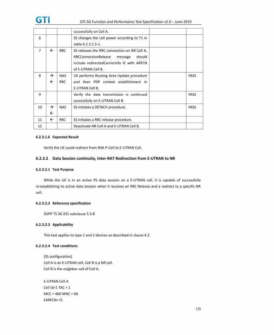
GTI 5G Function and Performance Test Specification v2.0 – June-2019
129
successfully on Cell A.
6 SS changes the cell power according to T1 in
table 6.2.3.1.5-1.
7 RRC SS releases the RRC connection on NR Cell A,
RRCConnectionRelease message should
include redirectedCarrierInfo IE with ARFCN
of E-UTRAN Cell B.
8
NAS
RRC
UE performs Routing Area Update procedure
and then PDP context establishment in
E-UTRAN Cell B.
PASS
9 Verify the data transmission is continued
successfully on E-UTRAN Cell B.
PASS
10
NAS SS initiates a DETACH procedure. PASS
11 RRC SS initiates a RRC release procedure.
12 Deactivate NR Cell A and E-UTRAN Cell B.
6.2.3.1.6 Expected Result
Verify the UE could redirect from NSA P-Cell to E-UTRAN Cell.
6.2.3.2 Data Session continuity, Inter-RAT Redirection from E-UTRAN to NR
6.2.3.2.1 Test Purpose
While the UE is in an active PS data session on a E-UTRAN cell, it is capable of successfully
re-establishing its active data session when it receives an RRC Release and a redirect to a specific NR
cell .
6.2.3.2.2 Reference specification
3GPP TS 36.331 subclause 5.3.8
6.2.3.2.3 Applicability
This test applies to type 1 and 2 devices as described in clause 4.2.
6.2.3.2.4 Test conditions
[SS configuration]
Cell A is an E-UTRAN cell, Cell B is a NR cell.
Cell B is the neighbor cell of Cell A.
E-UTRAN Cell A
Cell Id=1 TAC = 1
MCC = 460 MNC = 00
EARFCN= f1

GTI 5G Function and Performance Test Specification v2.0 – June-2019
130
rootSequenceIndex = 0
Reference Signal EPRE = -85 dBm/15kHz
NR Cell B
Cell Id=2 TAC = 2
MCC = 460 MNC = 00
NR-ARFCN= f1
SS/PBCH SSS EPRE = -125 dBm/30kHz
[UE configuration]
The test USIM shall be inserted.
The UE is in AUTOMATIC network selection mode.
UE works in SA mode.
[Initial conditions]
SS
E-UTRAN Cell A is not active.
NR Cell B is not active.
The test shall be performed under ideal radio conditions.
UE
UE is powered off
6.2.3.2.5 Test procedure
Table 5.1.1.5-1: Time of cell power level and parameter changes
Time E-UTRAN Cell A NR Cell B Remark
T0 -85 Not Active
T1 -97 -85
PREAMBLE
1. Activate E-UTRAN Cell A and NR Cell B.The SS configures the corresponding Master
Information Block and System Information Block broadcast.
2. The SS configures the initial power according to T0 in Table 6.2.3.2.5-1.
3. The UE is powered ON.
MAIN BODY
4. The UE performs the registration procedure with activation of the initial default EPS bearer
on Cell A (see 36.508, 4.5.2 ).
5. Verify the data transmission is performed successfully on E-UTRAN Cell A.
6. The SS changes cell power according to T1 in table 6.2.3.2.5-1.
7. The SS releases the RRC connection on E-UTRAN Cell A, RRCConnectionRelease message
should include redirectedCarrierInfo IE with CarrierInfoNR of NR Cell B.
8. The UE performs the registration procedure for mobility on NR Cell B according to subclause
5.4.1 step3-18.

GTI 5G Function and Performance Test Specification v2.0 – June-2019
131
9. Verify the data transmission is performed successfully on NR Cell B.
POSTAMBLE
10. The SS initiates a Detach procedure.
11. The SS initiates a RRC release procedure.
12. Deactivate E-UTRAN Cell A and NR Cell B.
Table 5.1.1.5-2: Message Sequence
Step Message Sequence Verdict
U-S Layer Message Specific Contents
1 RRC Activate E-UTRAN Cell A and NR Cell B.
2 SS configures the initial power according to
T0 in Table 6.2.3.2.5-1.
3 UE Switch On UE AT Command
4
NAS
RRC
UE performs the registration procedure with
activation of the initial default EPS bearer on
Cell A (see 36.508, 4.5.2 ).
PASS
5 Verify the data transmission is performed
successfully on E-UTRAN Cell A.
PASS
6 SS changes cell power according to T1 in
table 6.2.3.2.5-1.
7 RRC SS releases the RRC connection on E-UTRAN
Cell A, RRCConnectionRelease message
should include redirectedCarrierInfo IE with
CarrierInfoNR of NR Cell B.
8
NAS
RRC
UE performs the registration procedure for
mobility on NR Cell B according to subclause
5.4.1 step3-18.
PASS
9 Verify the data transmission is performed
successfully on NR Cell B.
PASS
10
NAS SS initiates a de-registration procedure. PASS
11 RRC SS initiates a RRC release procedure.
12 Deactivate E-UTRAN Cell A and NR Cell B.
6.2.3.2.6 Expected Result
Verify the UE could redirect from E-UTRAN Cell to NSA P-Cell.
6.3 NSA
6.3.1 Cell Reselection, from NSA P-Cell to E-UTRAN cell
6.3.1.1 Test Purpose

GTI 5G Function and Performance Test Specification v2.0 – June-2019
132
UE could reselect from NSA P-Cell to E-UTRAN Cell. UE works in 4G mode.
6.3.1.2 Reference specification
TS 36.304, clause 5.2.4
6.3.1.3 Applicability
This test applies to the device that supports NSA or SA+NSA.
6.3.1.4 Test conditions
[SS configuration]
CellA and Cell B are E-UTRAN Cells, CellC is a NR Cell.
Cell A supports NSA, Cell B is a Neighbor Cell of Cell A.
E-UTRAN Cell A
Cell Id=01 TAC = 01
MCC-MNC = 460-00
EARFCN= f1
rootSequenceIndex = 0
Reference Signal EPRE= -85 dBm/15kHz
upperLayerIndication-r15=true
E-UTRAN Cell B
Cell Id=02 TAC = 02
MCC-MNC = 460-00
EARFCN= f2
rootSequenceIndex = 8
Reference Signal EPRE= -125 dBm/15kHz
NR Cell C
Cell Id=03 TAC = 01
MCC = 460 MNC = 00
NR-ARFCN= f1
SS/PBCH SSS EPRE = -125 dBm/30kHz
[UE configuration]
The test UICC with USIM should be inserted
The UE is in AUTOMATIC network selection mode.
UE works in NSA mode.
[Initial conditions]
SS
E-UTRAN Cell A is not active
E-UTRAN Cell B is not active

GTI 5G Function and Performance Test Specification v2.0 – June-2019
133
NR Cell C is not active
The test shall be performed under ideal radio conditions.
UE
UE is powered off
6.3.1.5 Test procedure
Table 5.1.1.5-1: Time of cell power level and parameter changes
Time E-UTRAN Cell A E-UTRAN Cell B NR Cell C Remark
T0 -85 Not Active -90
T1 -90 -85 -90
PREAMBLE
20. Activate E-UTRAN Cell A,E-UTRAN Cell B and NR Cell C.The SS configures the corresponding
Master Information Block and System Information Block broadcast.
21. The SS configures the initial power according to T0 in Table 6.3.1.5-1.
22. The UE is powered ON.
MAIN BODY
23. The UE performs the registration procedure with activation of the initial default EPS bearer
on Cell A (see 36.508, 4.5.2 ).
24. The SS sends an ue-CapabilityRequest including the RAT type “eutra-nr”.
25. Verify the UE sends UECapabilityInformation message including the RAT type “eutra-nr”.
26. The SS sends an RRCConnectionReconfiguration message containing NR RRCReconfiguration
message to add Cell C as NR PS-Cell with Split DRB. RRCConnectionReconfiguration message
contains the ACTIVATE DEDICATED EPS BEARER CONTEXT REQUEST message.
27. The UE sends an RRCConnectionReconfigurationComplete message containing NR
RRCReconfigurationComplete message.
28. The UE sends an ULInformationTransfer message containing the ACTIVATE DEDICATED EPS
BEARER CONTEXT ACCEPT message.
29. Verify the data transmission is performed successfully on NR Cell C.
30. The RRC connection is released by the SS.
31. The SS changes cell power according to T1 in table 6.3.1.5-1.
32. The UE performs TRACKING AREA UPDATE on Cell B.
33. Verify the data transmission is performed successfully on E-UTRAN Cell B.
POSTAMBLE
34. The SS initiates a Detach procedure.
35. The SS initiates a RRC release procedure.
36. Deactivate E-UTRAN Cell A,E-UTRAN Cell B and NR Cell C.
Table 6.3.1.55.1.1.5-2: Message Sequence
Step Message Sequence Verdict
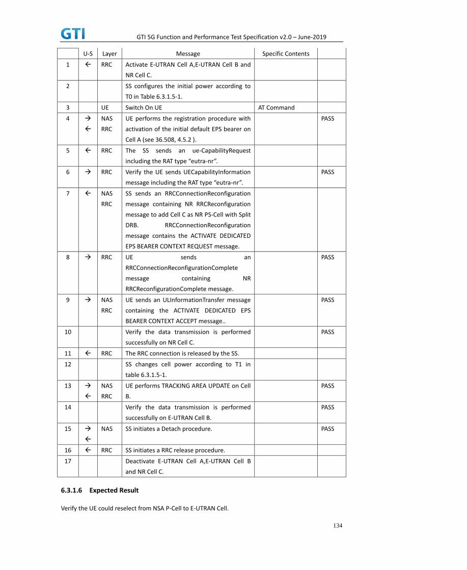
GTI 5G Function and Performance Test Specification v2.0 – June-2019
134
U-S Layer Message Specific Contents
1 RRC Activate E-UTRAN Cell A,E-UTRAN Cell B and
NR Cell C.
2 SS configures the initial power according to
T0 in Table 6.3.1.5-1.
3 UE Switch On UE AT Command
4
NAS
RRC
UE performs the registration procedure with
activation of the initial default EPS bearer on
Cell A (see 36.508, 4.5.2 ).
PASS
5 RRC The SS sends an ue-CapabilityRequest
including the RAT type “eutra-nr”.
6 RRC Verify the UE sends UECapabilityInformation
message including the RAT type “eutra-nr”.
PASS
7 NAS
RRC
SS sends an RRCConnectionReconfiguration
message containing NR RRCReconfiguration
message to add Cell C as NR PS-Cell with Split
DRB. RRCConnectionReconfiguration
message contains the ACTIVATE DEDICATED
EPS BEARER CONTEXT REQUEST message.
8 RRC UE sends an
RRCConnectionReconfigurationComplete
message containing NR
RRCReconfigurationComplete message.
PASS
9 NAS
RRC
UE sends an ULInformationTransfer message
containing the ACTIVATE DEDICATED EPS
BEARER CONTEXT ACCEPT message..
PASS
10 Verify the data transmission is performed
successfully on NR Cell C.
PASS
11 RRC The RRC connection is released by the SS.
12 SS changes cell power according to T1 in
table 6.3.1.5-1.
13
NAS
RRC
UE performs TRACKING AREA UPDATE on Cell
B.
PASS
14 Verify the data transmission is performed
successfully on E-UTRAN Cell B.
PASS
15
NAS SS initiates a Detach procedure. PASS
16 RRC SS initiates a RRC release procedure.
17 Deactivate E-UTRAN Cell A,E-UTRAN Cell B
and NR Cell C.
6.3.1.6 Expected Result
Verify the UE could reselect from NSA P-Cell to E-UTRAN Cell.

GTI 5G Function and Performance Test Specification v2.0 – June-2019
135
6.3.2 Cell Reselection, from E-UTRAN cell to NSA P-Cell
6.3.2.1 Test Purpose
UE could reselect from E-UTRAN Cell to NSA P-Cell. Initial UL data trasfer, UE report NSA
capability then SCG PS-Cell establishment
6.3.2.2 Reference specification
TS 36.304, clause 5.2.4
6.3.2.3 Applicability
This test applies to the device that supports NSA or SA+NSA.
6.3.2.4 Test conditions
[SS configuration]
CellA and Cell B are E-UTRAN Cells, CellC is a NR Cell.
Cell B supports NSA, it is a Neighbor Cell of Cell A.
E-UTRAN Cell A
Cell Id=01 TAC = 01
MCC-MNC = 460-00
EARFCN= f2
rootSequenceIndex = 0
Reference Signal EPRE= -85 dBm/15kHz
E-UTRAN Cell B
Cell Id=02 TAC = 02
MCC-MNC = 460-00
EARFCN= f1
rootSequenceIndex = 8
Reference Signal EPRE= -125 dBm/15kHz
upperLayerIndication-r15=true
NR Cell C
Cell Id=03 TAC = 02
MCC = 460 MNC = 00
NR-ARFCN= f1
SS/PBCH SSS EPRE = -125 dBm/30kHz
[UE configuration]
The test UICC with USIM should be inserted
The UE is in AUTOMATIC network selection mode.

GTI 5G Function and Performance Test Specification v2.0 – June-2019
136
UE works in NSA mode.
[Initial conditions]
SS
E-UTRAN Cell A is not active
E-UTRAN Cell B is not active
NR Cell C is not active
The test shall be performed under ideal radio conditions.
UE
UE is powered off
6.3.2.5 Test procedure
Table 6.3.2.55.1.1.5-1: Time of cell power level and parameter changes
Time Cell A Cell B Cell C Remark
T0 -85 Not Active Not Active
T1 -91 -85 -94
PREAMBLE
1. Activate E-UTRAN Cell A,E-UTRAN Cell B and NR Cell C.The SS configures the corresponding
Master Information Block and System Information Block broadcast.
2. The SS configures the initial power according to T0 in Table 6.3.2.5-1.
3. The UE is powered ON.
MAIN BODY
4. The UE performs the registration procedure with activation of the initial default EPS bearer
on Cell A (see 36.508, 4.5.2 ).
5. The SS sends an ue-CapabilityRequest including the RAT type “eutra-nr”.
6. Verify the UE sends UECapabilityInformation message including the RAT type “eutra-nr”.
7. Verify the data transmission is performed successfully on E-UTRAN Cell A.
8. The RRC connection is released by the SS.
9. The SS changes cell power according to T1 in table 6.3.2.5-1.
10. The UE performs TRACKING AREA UPDATE on Cell B.
11. The SS sends an RRCConnectionReconfiguration message containing NR RRCReconfiguration
message to add Cell C as NR PS-Cell with Split DRB. RRCConnectionReconfiguration message
contains the ACTIVATE DEDICATED EPS BEARER CONTEXT REQUEST message.
12. The UE sends an RRCConnectionReconfigurationComplete message containing NR
RRCReconfigurationComplete message.
13. The UE sends an ULInformationTransfer message containing the ACTIVATE DEDICATED EPS
BEARER CONTEXT ACCEPT message.
14. Verify the data transmission is performed successfully on NR Cell C.
POSTAMBLE

GTI 5G Function and Performance Test Specification v2.0 – June-2019
137
15. The SS initiates a Detach procedure.
16. The SS initiates a RRC release procedure.
17. Deactivate E-UTRAN Cell A,E-UTRAN Cell B and NR Cell C.
Table 5.1.1.5-2: Message Sequence
Step Message Sequence Verdict
U-S Layer Message Specific Contents
1 RRC Activate E-UTRAN Cell A,E-UTRAN Cell B and
NR Cell C.
2 SS configures the initial power according to
T0 in Table 6.3.2.5-1.
3 UE Switch On UE AT Command
4
NAS
RRC
UE performs the registration procedure with
activation of the initial default EPS bearer on
Cell A (see 36.508, 4.5.2 ).
PASS
5 RRC The SS sends an ue-CapabilityRequest
including the RAT type “eutra-nr”.
6 RRC Verify the UE sends UECapabilityInformation
message including the RAT type “eutra-nr”.
PASS
7 Verify the data transmission is performed
successfully on E-UTRAN Cell A.
PASS
8 RRC The RRC connection is released by the SS.
9 SS changes cell power according to T1 in
table 6.3.2.5-1.
10
NAS
RRC
UE performs TRACKING AREA UPDATE on Cell
B.
PASS
11 NAS
RRC
SS sends an RRCConnectionReconfiguration
message containing NR RRCReconfiguration
message to add Cell C as NR PS-Cell with Split
DRB. RRCConnectionReconfiguration
message contains the ACTIVATE DEDICATED
EPS BEARER CONTEXT REQUEST message.
12 RRC UE sends an
RRCConnectionReconfigurationComplete
message containing NR
RRCReconfigurationComplete message.
PASS
13 NAS
RRC
UE sends an ULInformationTransfer message
containing the ACTIVATE DEDICATED EPS
BEARER CONTEXT ACCEPT message..
PASS
14 Verify the data transmission is performed
successfully on NR Cell C.
PASS
15
NAS SS initiates a Detach procedure. PASS

GTI 5G Function and Performance Test Specification v2.0 – June-2019
138
16 RRC SS initiates a RRC release procedure.
17 Deactivate E-UTRAN Cell A,E-UTRAN Cell B
and NR Cell C.
6.3.2.6 Expected Result
Verify the UE could reselect from E-UTRAN Cell to NSA P-Cell.
6.3.3 P-Cell Handover with SCG change, Data continuity
6.3.3.1 Test Purpose
Setup a real PS service (e.g. streaming).The UE perform P-Cell-P-Cell handover with SCG change.
6.3.3.2 Reference specification
3GPP TS 36.331 subclause 5.3.5
3GPP TS 38.331 subclause 5.3.5
6.3.3.3 Applicability
This test applies to the device that supports NSA or SA+NSA.
6.3.3.4 Test conditions
[SS configuration]
CellA and Cell B are E-UTRAN Cells, CellC and Cell D are NR Cells.
Cell A and Cell B supports NSA.
E-UTRAN Cell A
Cell Id=01 TAC = 01
MCC-MNC = 460-00
Frequency Configuration = f1
rootSequenceIndex = 0
Reference Signal EPRE= -85 dBm/15kHz
upperLayerIndication-r15=true
E-UTRAN Cell B
Cell Id=02 TAC = 02
MCC-MNC = 460-00
Frequency Configuration = f2
rootSequenceIndex = 8
Reference Signal EPRE= -85 dBm/15kHz
upperLayerIndication-r15=true
NR Cell C
Cell Id=03 TAC = 01
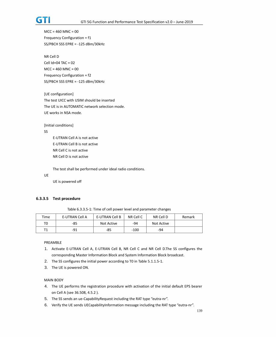
GTI 5G Function and Performance Test Specification v2.0 – June-2019
139
MCC = 460 MNC = 00
Frequency Configuration = f1
SS/PBCH SSS EPRE = -125 dBm/30kHz
NR Cell D
Cell Id=04 TAC = 02
MCC = 460 MNC = 00
Frequency Configuration = f2
SS/PBCH SSS EPRE = -125 dBm/30kHz
[UE configuration]
The test UICC with USIM should be inserted
The UE is in AUTOMATIC network selection mode.
UE works in NSA mode.
[Initial conditions]
SS
E-UTRAN Cell A is not active
E-UTRAN Cell B is not active
NR Cell C is not active
NR Cell D is not active
The test shall be performed under ideal radio conditions.
UE
UE is powered off
6.3.3.5 Test procedure
Table 6.3.3.5-1: Time of cell power level and parameter changes
Time E-UTRAN Cell A E-UTRAN Cell B NR Cell C NR Cell D Remark
T0 -85 Not Active -94 Not Active
T1 -91 -85 -100 -94
PREAMBLE
1. Activate E-UTRAN Cell A, E-UTRAN Cell B, NR Cell C and NR Cell D.The SS configures the
corresponding Master Information Block and System Information Block broadcast.
2. The SS configures the initial power according to T0 in Table 5.1.1.5-1.
3. The UE is powered ON.
MAIN BODY
4. The UE performs the registration procedure with activation of the initial default EPS bearer
on Cell A (see 36.508, 4.5.2 ).
5. The SS sends an ue-CapabilityRequest including the RAT type “eutra-nr”.
6. Verify the UE sends UECapabilityInformation message including the RAT type “eutra-nr”.

GTI 5G Function and Performance Test Specification v2.0 – June-2019
140
7. The SS sends an RRCConnectionReconfiguration message containing NR RRCReconfiguration
message to add Cell C as NR PS-Cell with Split DRB. RRCConnectionReconfiguration message
contains the ACTIVATE DEDICATED EPS BEARER CONTEXT REQUEST message.
8. The UE sends an RRCConnectionReconfigurationComplete message containing NR
RRCReconfigurationComplete message.
9. The UE sends an ULInformationTransfer message containing the ACTIVATE DEDICATED EPS
BEARER CONTEXT ACCEPT message.
10. Verify the data transmission is performed successfully on NR Cell C.
11. The SS changes cell power according to T1 in table 6.3.3.5-1.
12. The SS sends an RRCConnectionReconfiguration message containing mobilityControlInfo to
handover to E-UTRA Cell B and NR RRCReconfiguration message to perform SCG change with
reconfigurationWithSync on Cell D.
13. The UE sends an RRCConnectionReconfigurationComplete message containing NR
RRCReconfigurationComplete message.
14. The UE performs TRACKING AREA UPDATE on Cell B.
15. Verify the data transmission is performed successfully on NR Cell D.
POSTAMBLE
16. The SS initiates a Detach procedure.
17. The SS initiates a RRC release procedure.
18. Deactivate E-UTRAN Cell A, E-UTRAN Cell B, NR Cell C and NR Cell D.
Table 6.3.3.5-2: Message Sequence
Step Message Sequence Verdict
U-S Layer Message Specific
Contents
1 RRC Activate E-UTRAN Cell A, E-UTRAN Cell B, NR Cell
C and NR Cell D.
2 SS configures the initial power according to T0 in
Table 6.3.3.5-1.
3 UE Switch On UE AT Command
4
NAS
RRC
UE performs the registration procedure with
activation of the initial default EPS bearer on Cell
A (see 36.508, 4.5.2 ).
PASS
5 RRC The SS sends an ue-CapabilityRequest including
the RAT type “eutra-nr”.
6 RRC Verify the UE sends UECapabilityInformation
message including the RAT type “eutra-nr”.
PASS
7 NAS
RRC
SS sends an RRCConnectionReconfiguration
message containing NR RRCReconfiguration
message to add Cell C as NR PS-Cell with Split
DRB. RRCConnectionReconfiguration message
contains the ACTIVATE DEDICATED EPS BEARER
CONTEXT REQUEST message.
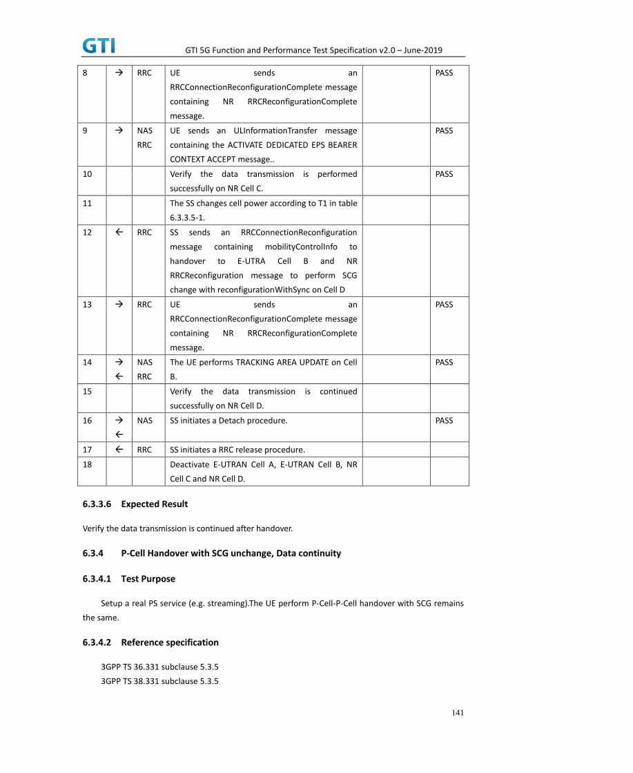
GTI 5G Function and Performance Test Specification v2.0 – June-2019
141
8 RRC UE sends an
RRCConnectionReconfigurationComplete message
containing NR RRCReconfigurationComplete
message.
PASS
9 NAS
RRC
UE sends an ULInformationTransfer message
containing the ACTIVATE DEDICATED EPS BEARER
CONTEXT ACCEPT message..
PASS
10 Verify the data transmission is performed
successfully on NR Cell C.
PASS
11 The SS changes cell power according to T1 in table
6.3.3.5-1.
12 RRC SS sends an RRCConnectionReconfiguration
message containing mobilityControlInfo to
handover to E-UTRA Cell B and NR
RRCReconfiguration message to perform SCG
change with reconfigurationWithSync on Cell D
13 RRC UE sends an
RRCConnectionReconfigurationComplete message
containing NR RRCReconfigurationComplete
message.
PASS
14
NAS
RRC
The UE performs TRACKING AREA UPDATE on Cell
B.
PASS
15 Verify the data transmission is continued
successfully on NR Cell D.
16
NAS SS initiates a Detach procedure. PASS
17 RRC SS initiates a RRC release procedure.
18 Deactivate E-UTRAN Cell A, E-UTRAN Cell B, NR
Cell C and NR Cell D.
6.3.3.6 Expected Result
Verify the data transmission is continued after handover.
6.3.4 P-Cell Handover with SCG unchange, Data continuity
6.3.4.1 Test Purpose
Setup a real PS service (e.g. streaming).The UE perform P-Cell-P-Cell handover with SCG remains
the same.
6.3.4.2 Reference specification
3GPP TS 36.331 subclause 5.3.5
3GPP TS 38.331 subclause 5.3.5

GTI 5G Function and Performance Test Specification v2.0 – June-2019
142
6.3.4.3 Applicability
This test applies to the device that supports NSA or SA+NSA.
6.3.4.4 Test conditions
[SS configuration]
CellA and Cell B are E-UTRAN Cells, CellC is a NR Cell.
Cell A and Cell B supports NSA.
E-UTRAN Cell A
Cell Id=01 TAC = 01
MCC-MNC = 460-00
EARFCN= f1
rootSequenceIndex = 0
Reference Signal EPRE= -85 dBm/15kHz
upperLayerIndication-r15=true
E-UTRAN Cell B
Cell Id=02 TAC = 01
MCC-MNC = 460-00
EARFCN= f2
rootSequenceIndex = 8
Reference Signal EPRE= -85 dBm/15kHz
upperLayerIndication-r15=true
NR Cell C
Cell Id=03 TAC = 01
MCC = 460 MNC = 00
NR-ARFCN= f1
SS/PBCH SSS EPRE = -125 dBm/30kHz
[UE configuration]
The test UICC with USIM should be inserted
The UE is in AUTOMATIC network selection mode.
UE works in NSA mode.
[Initial conditions]
SS
E-UTRAN Cell A is not active
E-UTRAN Cell B is not active
NR Cell C is not active
The test shall be performed under ideal radio conditions.
UE

GTI 5G Function and Performance Test Specification v2.0 – June-2019
143
UE is powered off
6.3.4.5 Test procedure
Table 5.1.1.5-1: Time of cell power level and parameter changes
Time E-UTRAN Cell A E-UTRAN Cell B NR Cell C Remark
T0 -85 Not Active -94
T1 -91 -85 -94
PREAMBLE
1. Activate E-UTRAN Cell A,E-UTRAN Cell B and NR Cell C.The SS configures the corresponding
Master Information Block and System Information Block broadcast.
2. The SS configures the initial power according to T0 in Table 6.3.4.5-1.
3. The UE is powered ON.
MAIN BODY
4. The UE performs the registration procedure with activation of the initial default EPS bearer
on Cell A (see 36.508, 4.5.2 ).
5. The SS sends an ue-CapabilityRequest including the RAT type “eutra-nr”.
6. Verify the UE sends UECapabilityInformation message including the RAT type “eutra-nr”.
7. The SS sends an RRCConnectionReconfiguration message containing NR RRCReconfiguration
message to add Cell C as NR PS-Cell with Split DRB. RRCConnectionReconfiguration message
contains the ACTIVATE DEDICATED EPS BEARER CONTEXT REQUEST message.
8. The UE sends an RRCConnectionReconfigurationComplete message containing NR
RRCReconfigurationComplete message.
9. The UE sends an ULInformationTransfer message containing the ACTIVATE DEDICATED EPS
BEARER CONTEXT ACCEPT message.
10. Verify the data transmission is performed successfully on NR Cell C.
11. The SS changes cell power according to T1 in table 6.3.4.5-1.
12. The SS sends an RRCConnectionReconfiguration message containing mobilityControlInfo to
handover to E-UTRA Cell B and SCG remains the same.
13. The UE sends an RRCConnectionReconfigurationComplete message.
14. Verify the data transmission is continued successfully on NR Cell C.
POSTAMBLE
15. The SS initiates a Detach procedure.
16. The SS initiates a RRC release procedure.
17. Deactivate E-UTRAN Cell A,E-UTRAN Cell B and NR Cell C.
Table 5.1.1.5-2: Message Sequence
Step Message Sequence Verdict
U-S Layer Message Specific Contents
1 RRC Activate E-UTRAN Cell A,E-UTRAN Cell B and
NR Cell C.
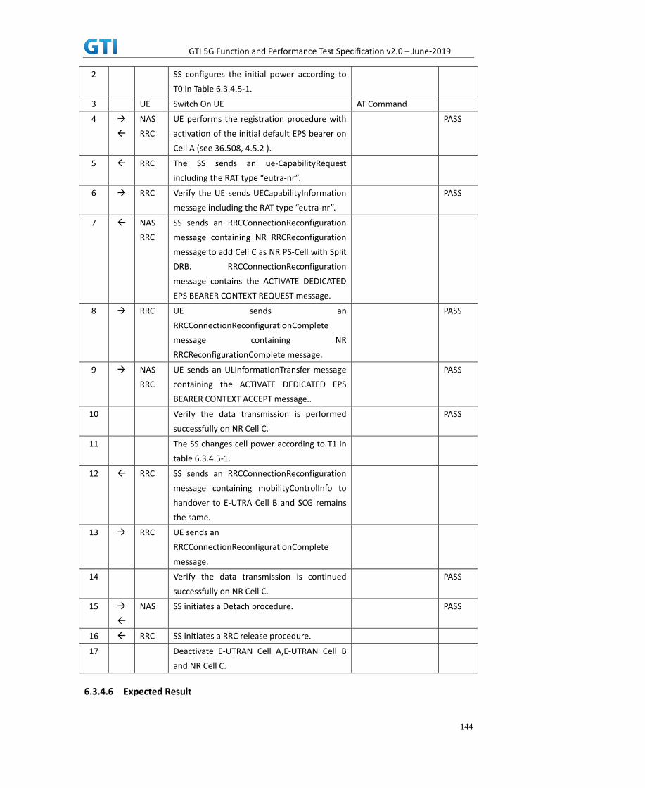
GTI 5G Function and Performance Test Specification v2.0 – June-2019
144
2 SS configures the initial power according to
T0 in Table 6.3.4.5-1.
3 UE Switch On UE AT Command
4
NAS
RRC
UE performs the registration procedure with
activation of the initial default EPS bearer on
Cell A (see 36.508, 4.5.2 ).
PASS
5 RRC The SS sends an ue-CapabilityRequest
including the RAT type “eutra-nr”.
6 RRC Verify the UE sends UECapabilityInformation
message including the RAT type “eutra-nr”.
PASS
7 NAS
RRC
SS sends an RRCConnectionReconfiguration
message containing NR RRCReconfiguration
message to add Cell C as NR PS-Cell with Split
DRB. RRCConnectionReconfiguration
message contains the ACTIVATE DEDICATED
EPS BEARER CONTEXT REQUEST message.
8 RRC UE sends an
RRCConnectionReconfigurationComplete
message containing NR
RRCReconfigurationComplete message.
PASS
9 NAS
RRC
UE sends an ULInformationTransfer message
containing the ACTIVATE DEDICATED EPS
BEARER CONTEXT ACCEPT message..
PASS
10 Verify the data transmission is performed
successfully on NR Cell C.
PASS
11 The SS changes cell power according to T1 in
table 6.3.4.5-1.
12 RRC SS sends an RRCConnectionReconfiguration
message containing mobilityControlInfo to
handover to E-UTRA Cell B and SCG remains
the same.
13 RRC UE sends an
RRCConnectionReconfigurationComplete
message.
14 Verify the data transmission is continued
successfully on NR Cell C.
PASS
15
NAS SS initiates a Detach procedure. PASS
16 RRC SS initiates a RRC release procedure.
17 Deactivate E-UTRAN Cell A,E-UTRAN Cell B
and NR Cell C.
6.3.4.6 Expected Result

GTI 5G Function and Performance Test Specification v2.0 – June-2019
145
Verify the data transmission is continued after handover.
6.3.5 Data Session continuity, from NSA cell to E-UTRAN cell
6.3.5.1 Test Purpose
While the UE is in an active PS data session on a NSA PS-Cell, UE can keep data transmission
continuity after releasing of NSA PS-Cell and handover from NSA P-Cell to E-UTRAN cell.
6.3.5.2 Reference specification
3GPP TS 36.331 subclause 5.3.5
3GPP TS 38.331 subclause 5.3.5
6.3.5.3 Applicability
This test applies to the device that supports NSA or SA+NSA.
6.3.5.4 Test conditions
[SS configuration]
CellA and Cell B are inter-band E-UTRAN Cells, CellC is a NR Cell.
Cell A supports NSA, Cell B is a 4G only Neighbor Cell of Cell A.
E-UTRAN Cell A
Cell Id=01 TAC = 01
MCC-MNC = 460-00
EARFCN= f1
rootSequenceIndex = 0
Reference Signal EPRE= -85 dBm/15kHz
upperLayerIndication-r15=true
E-UTRAN Cell B
Cell Id=02 TAC = 02
MCC-MNC = 460-00
EARFCN= f1
rootSequenceIndex = 8
Reference Signal EPRE= -125 dBm/15kHz
NR Cell C
Cell Id=03 TAC = 01
MCC = 460 MNC = 00
NR-ARFCN= f1
SS/PBCH SSS EPRE = -125 dBm/30kHz
Band configuration:

GTI 5G Function and Performance Test Specification v2.0 – June-2019
146
- Cell A is Band 3. Cell B is Band 39. Cell C is n41
[UE configuration]
The test UICC with USIM should be inserted
The UE is in AUTOMATIC network selection mode.
UE works in NSA mode.
[Initial conditions]
SS
E-UTRAN Cell A is not active
E-UTRAN Cell B is not active
NR Cell C is not active
The test shall be performed under ideal radio conditions.
UE
UE is powered off
6.3.5.5 Test procedure
Table 6.3.5.5-1: Time of cell power level and parameter changes
Time E-UTRAN Cell A E-UTRAN Cell B NR Cell C Remark
T0 -85 Not Active -94
T1 -91 -85 -94
PREAMBLE
1. Activate E-UTRAN Cell A,E-UTRAN Cell B and NR Cell C.The SS configures the corresponding
Master Information Block and System Information Block broadcast.
2. The SS configures the initial power according to T0 in Table 6.3.5.5-1.
3. The UE is powered ON.
MAIN BODY
4. The UE performs the registration procedure with activation of the initial default EPS bearer
on Cell A (see 36.508, 4.5.2 ).
5. The SS sends an ue-CapabilityRequest including the RAT type “eutra-nr”.
6. Verify the UE sends UECapabilityInformation message including the RAT type “eutra-nr”.
7. The SS sends an RRCConnectionReconfiguration message containing NR RRCReconfiguration
message to add Cell C as NR PS-Cell with Split DRB. RRCConnectionReconfiguration message
contains the ACTIVATE DEDICATED EPS BEARER CONTEXT REQUEST message.
8. The UE sends an RRCConnectionReconfigurationComplete message containing NR
RRCReconfigurationComplete message.
9. The UE sends an ULInformationTransfer message containing the ACTIVATE DEDICATED EPS
BEARER CONTEXT ACCEPT message.
10. Verify the data transmission is performed successfully on NR Cell C.
11. The SS changes cell power according to T1 in table 6.3.5.5-1.

GTI 5G Function and Performance Test Specification v2.0 – June-2019
147
12. The SS sends an RRCConnectionReconfiguration message containing mobilityControlInfo to
handover to E-UTRA Cell B, and containing nr-Config for EN-DC release, and containing
RadioBearerConfig to release Split DRB.
13. The UE sends an RRCConnectionReconfigurationComplete message.
14. Verify the data transmission is continued successfully on E-UTRAN Cell B.
POSTAMBLE
15. The SS initiates a Detach procedure.
16. The SS initiates a RRC release procedure.
17. Deactivate E-UTRAN Cell A,E-UTRAN Cell B and NR Cell C.
Table 6.3.5.5-2: Message Sequence
Step Message Sequence Verdict
U-S Layer Message Specific Contents
1 RRC Activate E-UTRAN Cell A,E-UTRAN Cell B and
NR Cell C.
2 SS configures the initial power according to
T0 in Table 6.3.5.5-1.
3 UE Switch On UE AT Command
4
NAS
RRC
UE performs the registration procedure with
activation of the initial default EPS bearer on
Cell A (see 36.508, 4.5.2 ).
PASS
5 RRC The SS sends an ue-CapabilityRequest
including the RAT type “eutra-nr”.
6 RRC Verify the UE sends UECapabilityInformation
message including the RAT type “eutra-nr”.
PASS
7 NAS
RRC
SS sends an RRCConnectionReconfiguration
message containing NR RRCReconfiguration
message to add Cell C as NR PS-Cell with Split
DRB. RRCConnectionReconfiguration
message contains the ACTIVATE DEDICATED
EPS BEARER CONTEXT REQUEST message.
8 RRC UE sends an
RRCConnectionReconfigurationComplete
message containing NR
RRCReconfigurationComplete message.
PASS
9 NAS
RRC
UE sends an ULInformationTransfer message
containing the ACTIVATE DEDICATED EPS
BEARER CONTEXT ACCEPT message..
PASS
10 Verify the data transmission is performed
successfully on NR Cell C.
PASS
11 The SS changes cell power according to T1 in
table 6.3.5.5-1.
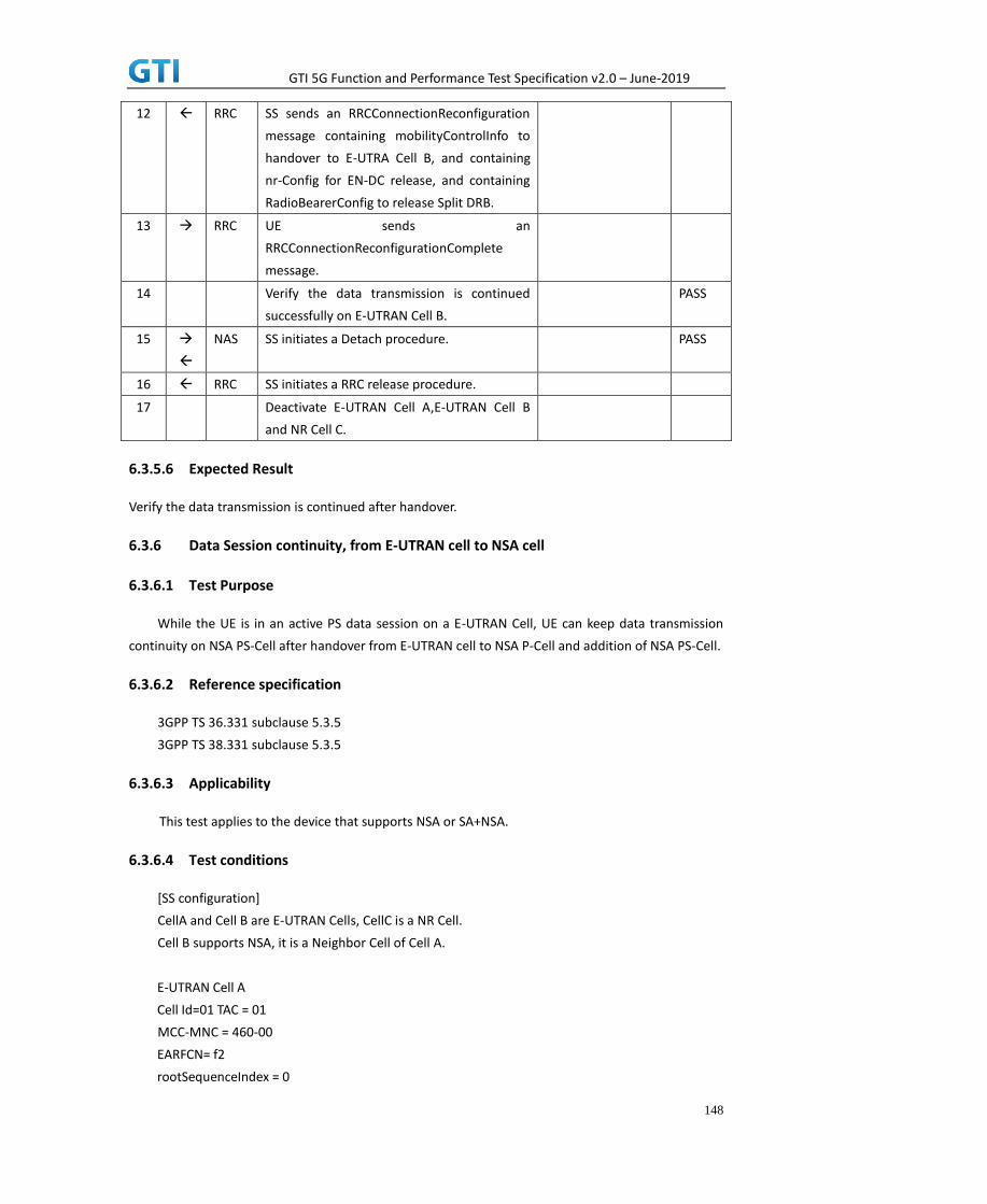
GTI 5G Function and Performance Test Specification v2.0 – June-2019
148
12 RRC SS sends an RRCConnectionReconfiguration
message containing mobilityControlInfo to
handover to E-UTRA Cell B, and containing
nr-Config for EN-DC release, and containing
RadioBearerConfig to release Split DRB.
13 RRC UE sends an
RRCConnectionReconfigurationComplete
message.
14 Verify the data transmission is continued
successfully on E-UTRAN Cell B.
PASS
15
NAS SS initiates a Detach procedure. PASS
16 RRC SS initiates a RRC release procedure.
17 Deactivate E-UTRAN Cell A,E-UTRAN Cell B
and NR Cell C.
6.3.5.6 Expected Result
Verify the data transmission is continued after handover.
6.3.6 Data Session continuity, from E-UTRAN cell to NSA cell
6.3.6.1 Test Purpose
While the UE is in an active PS data session on a E-UTRAN Cell, UE can keep data transmission
continuity on NSA PS-Cell after handover from E-UTRAN cell to NSA P-Cell and addition of NSA PS-Cell.
6.3.6.2 Reference specification
3GPP TS 36.331 subclause 5.3.5
3GPP TS 38.331 subclause 5.3.5
6.3.6.3 Applicability
This test applies to the device that supports NSA or SA+NSA.
6.3.6.4 Test conditions
[SS configuration]
CellA and Cell B are E-UTRAN Cells, CellC is a NR Cell.
Cell B supports NSA, it is a Neighbor Cell of Cell A.
E-UTRAN Cell A
Cell Id=01 TAC = 01
MCC-MNC = 460-00
EARFCN= f2
rootSequenceIndex = 0

GTI 5G Function and Performance Test Specification v2.0 – June-2019
149
Reference Signal EPRE= -85 dBm/15kHz
E-UTRAN Cell B
Cell Id=02 TAC = 02
MCC-MNC = 460-00
EARFCN= f1
rootSequenceIndex = 8
Reference Signal EPRE= -125 dBm/15kHz
upperLayerIndication-r15=true
NR Cell C
Cell Id=03 TAC = 02
MCC = 460 MNC = 00
NR-ARFCN= f1
SS/PBCH SSS EPRE = -125 dBm/30kHz
[UE configuration]
The test UICC with USIM should be inserted
The UE is in AUTOMATIC network selection mode.
UE works in NSA mode.
[Initial conditions]
SS
E-UTRAN Cell A is not active
E-UTRAN Cell B is not active
NR Cell C is not active
The test shall be performed under ideal radio conditions.
UE
UE is powered off
6.3.6.5 Test procedure
Table 5.1.1.5-1: Time of cell power level and parameter changes
Time E-UTRAN Cell A E-UTRAN Cell B NR Cell C Remark
T0 -85 Not Active Not Active
T1 -91 -85 -94
PREAMBLE
1. Activate E-UTRAN Cell A,E-UTRAN Cell B and NR Cell C.The SS configures the corresponding
Master Information Block and System Information Block broadcast.
2. The SS configures the initial power according to T0 in Table 6.3.6.5-1.
3. The UE is powered ON.

GTI 5G Function and Performance Test Specification v2.0 – June-2019
150
MAIN BODY
4. The UE performs the registration procedure with activation of the initial default EPS bearer
on Cell A (see 36.508, 4.5.2 ).
5. The SS sends an ue-CapabilityRequest including the RAT type “eutra-nr”.
6. Verify the UE sends UECapabilityInformation message including the RAT type “eutra-nr”.
7. Verify the data transmission is performed successfully on E-UTRAN Cell A.
8. The SS changes cell power according to T1 in table 6.3.6.5-1.
9. The SS sends an RRCConnectionReconfiguration message containing mobilityControlInfo to
handover to E-UTRA Cell B.
10. The UE sends an RRCConnectionReconfigurationComplete message.
11. The UE performs TRACKING AREA UPDATE on Cell B.
12. The SS sends an RRCConnectionReconfiguration message containing NR RRCReconfiguration
message to add Cell C as NR PS-Cell with Split DRB. RRCConnectionReconfiguration message
contains the ACTIVATE DEDICATED EPS BEARER CONTEXT REQUEST message.
13. The UE sends an RRCConnectionReconfigurationComplete message containing NR
RRCReconfigurationComplete message.
14. The UE sends an ULInformationTransfer message containing the ACTIVATE DEDICATED EPS
BEARER CONTEXT ACCEPT message.
15. Verify the data transmission is continued successfully on NR Cell C.
POSTAMBLE
16. The SS initiates a Detach procedure.
17. The SS initiates a RRC release procedure.
18. Deactivate E-UTRAN Cell A,E-UTRAN Cell B and NR Cell C.
Table 5.1.1.5-2: Message Sequence
Step Message Sequence Verdict
U-S Layer Message Specific Contents
1 RRC Activate E-UTRAN Cell A,E-UTRAN Cell B and NR
Cell C.
2 SS configures the initial power according to T0 in
Table 6.3.6.5-1.
3 UE Switch On UE AT Command
4
NAS
RRC
UE performs the registration procedure with
activation of the initial default EPS bearer on
Cell A (see 36.508, 4.5.2 ).
PASS
5 RRC The SS sends an ue-CapabilityRequest including
the RAT type “eutra-nr”.
6 RRC Verify the UE sends UECapabilityInformation
message including the RAT type “eutra-nr”.
PASS
7 Verify the data transmission is performed
successfully on E-UTRAN Cell A.
PASS
8 SS changes cell power according to T1 in table
6.3.6.5-1

GTI 5G Function and Performance Test Specification v2.0 – June-2019
151
9 RRC SS sends an RRCConnectionReconfiguration
message containing mobilityControlInfo to
handover to E-UTRA Cell B..
10 RRC UE sends an
RRCConnectionReconfigurationComplete
message.
PASS
11
NAS
RRC
UE performs TRACKING AREA UPDATE on Cell B. PASS
12 NAS
RRC
SS sends an RRCConnectionReconfiguration
message containing NR RRCReconfiguration
message to add Cell C as NR PS-Cell with Split
DRB. RRCConnectionReconfiguration message
contains the ACTIVATE DEDICATED EPS BEARER
CONTEXT REQUEST message.
13 RRC UE sends an
RRCConnectionReconfigurationComplete
message containing NR
RRCReconfigurationComplete message.
PASS
14 NAS
RRC
UE sends an ULInformationTransfer message
containing the ACTIVATE DEDICATED EPS
BEARER CONTEXT ACCEPT message..
PASS
15 Verify the data transmission is continued
successfully on NR Cell C.
PASS
16
NAS SS initiates a Detach procedure. PASS
17 RRC SS initiates a RRC release procedure.
18 Deactivate E-UTRAN Cell A,E-UTRAN Cell B and
NR Cell C.
6.3.6.6 Expected Result
Verify the data transmission is continued after handover.
6.3.7 SCG change with P-Cell remain the same, Data continuity
6.3.7.1 Test Purpose
Test to verify the support of SCG change when data transmission keep continuous.
6.3.7.2 Reference specification
3GPP TS 38.331 subclause 5.3.5
6.3.7.3 Applicability
This test applies to Type 1 and Type 3 devices as described in clause 4.2.

GTI 5G Function and Performance Test Specification v2.0 – June-2019
152
6.3.7.4 Test conditions
[SS configuration]
CellA is E-UTRAN Cells, Cell B and Cell C are NR intra-frequency cells.
Cell A and Cell B supports NSA.
E-UTRAN Cell A
Cell Id=01 TAC = 01
MCC-MNC = 460-00
Frequency Configuration = f1
rootSequenceIndex = 0
Reference Signal EPRE= -85 dBm/15kHz
upperLayerIndication-r15=true
NR Cell B
Cell Id=02 TAC = 01
MCC = 460 MNC = 00
Frequency Configuration = f1
SS/PBCH SSS EPRE = -125 dBm/30kHz
NR Cell C
Cell Id=03 TAC = 02
MCC = 460 MNC = 00
Frequency Configuration = f1
SS/PBCH SSS EPRE = -125 dBm/30kHz
[UE configuration]
The test UICC with USIM should be inserted
The UE is in AUTOMATIC network selection mode.
UE works in NSA mode.
[Initial conditions]
SS
E-UTRAN Cell A is not active
NR Cell B and Cell C are not active
The test shall be performed under ideal radio conditions.
UE
UE is powered off
6.3.7.5 Test procedure
Table 6.3.7.5-1: Time of cell power level and parameter changes Time Parameter Unit E-UTRAN Cell A NR Cell B NR Cell C Remark
T0 SS/PBCH, SSS EPRE dBm/SCS / -90 Not Active
Reference Signal EPRE dBm/15kHz -85 / /
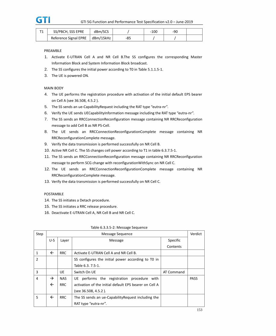
GTI 5G Function and Performance Test Specification v2.0 – June-2019
153
T1 SS/PBCH, SSS EPRE dBm/SCS / -100 -90
Reference Signal EPRE dBm/15kHz -85 / /
PREAMBLE
1. Activate E-UTRAN Cell A and NR Cell B.The SS configures the corresponding Master
Information Block and System Information Block broadcast.
2. The SS configures the initial power according to T0 in Table 5.1.1.5-1.
3. The UE is powered ON.
MAIN BODY
4. The UE performs the registration procedure with activation of the initial default EPS bearer
on Cell A (see 36.508, 4.5.2 ).
5. The SS sends an ue-CapabilityRequest including the RAT type “eutra-nr”.
6. Verify the UE sends UECapabilityInformation message including the RAT type “eutra-nr”.
7. The SS sends an RRCConnectionReconfiguration message containing NR RRCReconfiguration
message to add Cell B as NR PS-Cell.
8. The UE sends an RRCConnectionReconfigurationComplete message containing NR
RRCReconfigurationComplete message.
9. Verify the data transmission is performed successfully on NR Cell B.
10. Active NR Cell C. The SS changes cell power according to T1 in table 6.3.7.5-1.
11. The SS sends an RRCConnectionReconfiguration message containing NR RRCReconfiguration
message to perform SCG change with reconfigurationWithSync on NR Cell C.
12. The UE sends an RRCConnectionReconfigurationComplete message containing NR
RRCReconfigurationComplete message.
13. Verify the data transmission is performed successfully on NR Cell C.
POSTAMBLE
14. The SS initiates a Detach procedure.
15. The SS initiates a RRC release procedure.
16. Deactivate E-UTRAN Cell A, NR Cell B and NR Cell C.
Table 6.3.3.5-2: Message Sequence
Step Message Sequence Verdict
U-S Layer Message Specific
Contents
1 RRC Activate E-UTRAN Cell A and NR Cell B.
2 SS configures the initial power according to T0 in
Table 6.3. 7.5-1.
3 UE Switch On UE AT Command
4
NAS
RRC
UE performs the registration procedure with
activation of the initial default EPS bearer on Cell A
(see 36.508, 4.5.2 ).
PASS
5 RRC The SS sends an ue-CapabilityRequest including the
RAT type “eutra-nr”.

GTI 5G Function and Performance Test Specification v2.0 – June-2019
154
6 RRC Verify the UE sends UECapabilityInformation
message including the RAT type “eutra-nr”.
PASS
7 NAS
RRC
SS sends an RRCConnectionReconfiguration
message containing NR RRCReconfiguration
message to add Cell B as NR PS-Cell
8 RRC UE sends an
RRCConnectionReconfigurationComplete message
containing NR RRCReconfigurationComplete
message.
PASS
9 Verify the data transmission is performed
successfully on NR Cell B.
PASS
10 Active NR Cell C. The SS changes cell power
according to T1 in table 6.3.7.5-1.
11 RRC SS sends an RRCConnectionReconfiguration
message containing NR RRCReconfiguration
message to perform SCG change with
reconfigurationWithSync on Cell D
12 RRC UE sends RRCConnectionReconfigurationComplete
containing NR RRCReconfigurationComplete.
PASS
13 Verify the data transmission is continued
successfully on NR Cell D.
14
NAS SS initiates a Detach procedure. PASS
15 RRC SS initiates a RRC release procedure.
16 Deactivate E-UTRAN Cell A, NR Cell B and NR Cell C.
6.3.7.6 Expected Result
Verify the data transmission is continued after SCG change.
7 Service
7.1 Voice
7.1.1 Redirection from NR to E-UTRAN,MO call,SA mode.
7.1.1.1 Test Purpose
Verify that the UE will make a VoNR MO call,.then redirection from NR to E-UTRAN.
7.1.1.2 Reference specification
TS 36.508, TS 38.508,TS 34.229-1
7.1.1.3 Applicability

GTI 5G Function and Performance Test Specification v2.0 – June-2019
155
This test applies to type 1 and 2 devices as described in clause 4.2.
This test applies to the device that supports VoNR&VoLTE
7.1.1.4 Test conditions
[SS configuration]
Cell A is E-UTRAN Cell.
Cell B is a NR Cell.
Cell A supports SA and VoNR&VoLTE
E-UTRAN Cell A
Cell Id=01 TAC = 01
MCC-MNC = 460-00
E-UTRA Band = 41
EARFCN= f1
rootSequenceIndex TDD = 0
Reference Signal EPRE= -85 dBm/15kHz
upperLayerIndication-r15=true
NR Cell B
Cell Id=02 TAC = 01
MCC = 460 MNC = 00
NR-ARFCN= f1
SS/PBCH SSS EPRE = -125 dBm/30kHz
[UE configuration]
The test UICC with USIM should be inserted
The UE is in AUTOMATIC network selection mode.
UE works in SA mode.
IMS VoLTE Feature should be enabled on DUT
IMS VoNR Feature should be enabled on DUT
[Initial conditions]
SS
E-UTRAN Cell A is not active
NR Cell B is not active
The test shall be performed under ideal radio conditions.
UE
UE is powered off
7.1.1.5 Test procedure
Table 5.1.1.5-1: Time of cell power level and parameter changes

GTI 5G Function and Performance Test Specification v2.0 – June-2019
156
Time Parameter E-UTRAN Cell A NR Cell B
T0 SS/PBCH
SSS EPRE
-97 -85
T1 SS/PBCH
SSS EPRE
-85 -97
PREAMBLE
1. Activate E-UTRAN Cell A, NR Cell B.The SS configures the corresponding Master Information
Block and System Information Block broadcast.
2. The SS configures the initial power according to T0 in Table 7.1.1.5-1.
3. The UE is powered ON
MAIN BODY
4. The UE performs the registration procedure on Cell B (see 38.508, Table 4.5.2.2 till Step 18 ).
5. UE inititaes the PDU Session Establishment procedure for the IMS is completed in Cell B.
6. IMS Registration is successful in Cell B
7. The UE performs the IMS MO call procedure on Cell B.
8. The SS configures the initial power according to T1 in Table 7.1.1.5-1.
9. The SS send RRCRelease message with E-UTRAN cell information.
10. UE performs the TAU procedure for mobility on E-UTRAN Cell A.
11. SS initiated PDN connection modification to setup dedicated bearer for voice.
12. IMS Voice session establishment continued on Cell A.
POSTAMBLE
13. The UE is powered OFF
14. Deactivate E-UTRAN Cell A and NR Cell B.
Table 7.1.1.5-2: Message Sequence
Step Message Sequence Verdict
U-S Layer Message Specific Contents
1 RRC Activate E-UTRAN Cell A and NR Cell B.
2 SS configures the initial power according to T0
in Table 7.1.1.5-1.
3 UE Switch On UE AT Command
4
NAS
RRC
The UE performs the registration procedure on
Cell B (see 38.508, Table 4.5.2.2 till Step 18 ).
PASS
5 NAS
RRC
UE inititaes the PDU Session Establishment
procedure for the IMS is completed in Cell B
6
IMS Registration is successful in Cell B
7
The UE performs the IMS MO call procedure
on Cell B.
PASS
8 The SS configures the initial power according

GTI 5G Function and Performance Test Specification v2.0 – June-2019
157
to T1 in Table 7.1.1.5-1.
9 The SS send RRCRelease message with
E-UTRAN cell information
PASS
10
UE performs the TAU procedure for mobility
on E-UTRAN Cell A
PASS
11
SS initiated PDN connection modification to
setup dedicated bearer for voice.
12
IMS Voice session establishment continued on
Cell A.
PASS
13 UE Switch OFF UE AT Command
14 Deactivate E-UTRAN Cell A and NR Cell B.
7.1.1.6 Expected Result
Step 4, UE could select NR Cell B and camp on the NR Cell B.
Step 7, UE performs the IMS MO call procedure on Cell B
Step 9, SS RRCRelease message with E-UTRAN CellA information
Step 10, UE performs the TAU procedure for mobility on E-UTRAN Cell A
Step 12, IMS Voice session establishment continued on Cell A.
7.1.2 Redirection from NR to E-UTRAN,MT call,SA mode.
7.1.2.1 Test Purpose
Verify that the UE will make a VoNR MT call,.then redirection from NR to E-UTRAN..
7.1.2.2 Reference specification
TS 36.508, TS 38.508,TS 34.229-1
7.1.2.3 Applicability
This test applies to type 1 and 2 devices as described in clause 4.2.
This test applies to the device that supports VoNR&VoLTE
7.1.2.4 Test conditions
[SS configuration]
Cell A is E-UTRAN Cell.
Cell B is a NR Cell.
Cell A supports SA and VoNR&VoLTE
E-UTRAN Cell A
Cell Id=01 TAC = 01
MCC-MNC = 460-00
E-UTRA Band = 41
EARFCN= f1

GTI 5G Function and Performance Test Specification v2.0 – June-2019
158
rootSequenceIndex TDD = 0
Reference Signal EPRE= -85 dBm/15kHz
upperLayerIndication-r15=true
NR Cell B
Cell Id=02 TAC = 01
MCC = 460 MNC = 00
NR-ARFCN= f1
SS/PBCH SSS EPRE = -125 dBm/30kHz
[UE configuration]
The test UICC with USIM should be inserted
The UE is in AUTOMATIC network selection mode.
UE works in SA mode.
IMS VoLTE Feature should be enabled on DUT
IMS VoNR Feature should be enabled on DUT
[Initial conditions]
SS
E-UTRAN Cell A is not active
NR Cell B is not active
The test shall be performed under ideal radio conditions.
UE
UE is powered off
7.1.2.5 Test procedure
Table 5.1.1.5-1: Time of cell power level and parameter changes
Time Parameter E-UTRAN Cell A NR Cell B
T0 SS/PBCH
SSS EPRE
-97 -85
T1 SS/PBCH
SSS EPRE
-85 -97
PREAMBLE
1. Activate E-UTRAN Cell A, NR Cell B.The SS configures the corresponding Master Information
Block and System Information Block broadcast.
2. The SS configures the initial power according to T0 in Table 7.1.2.5-1.
3. The UE is powered ON
MAIN BODY
4. The UE performs the registration procedure on Cell B (see 38.508, Table 4.5.2.2 till Step 18 ).
5. UE inititaes the PDU Session Establishment procedure for the IMS is completed in Cell B.
6. IMS Registration is successful in Cell B

GTI 5G Function and Performance Test Specification v2.0 – June-2019
159
7. The UE performs the IMS MT call procedure on Cell B.
8. The SS configures the initial power according to T1 in Table 7.1.2.5-1.
9. The SS send RRCRelease message with E-UTRAN cell information.
10. UE performs the TAU procedure for mobility on E-UTRAN Cell A.
11. SS initiated PDN connection modification to setup dedicated bearer for voice.
12. IMS Voice session establishment continued on Cell A.
POSTAMBLE
13. The UE is powered OFF
14. Deactivate E-UTRAN Cell A and NR Cell B.
Table 7.1.2.5-2: Message Sequence
Step Message Sequence Verdict
U-S Layer Message Specific
Contents
1 RRC Activate E-UTRAN Cell A and NR Cell B.
2 SS configures the initial power according to T0 in
Table 7.1.2.5-1.
3 UE Switch On UE AT Command
4
NAS
RRC
The UE performs the registration procedure on
Cell B (see 38.508, Table 4.5.2.2 till Step 18 ).
PASS
5 NAS
RRC
UE inititaes the PDU Session Establishment
procedure for the IMS is completed in Cell B
6
IMS Registration is successful in Cell B
7
The UE performs the IMS MT call procedure on
Cell B.
PASS
8
The SS configures the initial power according to
T1 in Table 7.1.2.5-1.
9 The SS send RRCRelease message with E-UTRAN
cell information
PASS
10
UE performs the TAU procedure for mobility on
E-UTRAN Cell A
PASS
11
SS initiated PDN connection modification to setup
dedicated bearer for voice.
12
IMS Voice session establishment continued on
Cell A.
PASS
13 UE Switch OFF UE AT Command
14 Deactivate E-UTRAN Cell A and NR Cell B.
7.1.2.6 Expected Result
Step 4, UE could select NR Cell B and camp on the NR Cell B.

GTI 5G Function and Performance Test Specification v2.0 – June-2019
160
Step 7, UE performs the IMS MT call procedure on Cell B
Step 9, SS RRCRelease message with E-UTRAN CellA information
Step 10, UE performs the TAU procedure for mobility on E-UTRAN Cell A
Step 12, IMS Voice session establishment continued on Cell A.
7.1.3 VoLTE MO Call with E-UTRAN Cell, UE works in NSA mode.
7.1.3.1 Test Purpose
Verify that the UE will make a VoLTE MO call with E-UTRAN cell..
7.1.3.2 Reference specification
TS 36.508, TS 34.229-1
7.1.3.3 Applicability
This test applies to type 1 and 3 devices as described in clause 4.2.
This test applies to the device that supports VoLTE
7.1.3.4 Test conditions
[SS configuration]
Cell A is E-UTRAN Cell.
Cell B is a NR Cell.
Cell A supports NSA and VoLTE
E-UTRAN Cell A
Cell Id=01 TAC = 01
MCC-MNC = 460-00
E-UTRA Band = 41
EARFCN= f1
rootSequenceIndex TDD = 0
Reference Signal EPRE= -85 dBm/15kHz
upperLayerIndication-r15=true
NR Cell B
Cell Id=02 TAC = 01
MCC = 460 MNC = 00
NR-ARFCN= f1
SS/PBCH SSS EPRE = -125 dBm/30kHz
[UE configuration]
The test UICC with USIM should be inserted
The UE is in AUTOMATIC network selection mode.
UE works in NSA mode.
IMS VoLTE Feature should be enabled on DUT

GTI 5G Function and Performance Test Specification v2.0 – June-2019
161
[Initial conditions]
SS
E-UTRAN Cell A is not active
NR Cell B is not active
The test shall be performed under ideal radio conditions.
UE
UE is powered off
7.1.3.5 Test procedure
Table 5.1.1.5-1: Time of cell power level and parameter changes
Time Parameter E-UTRAN Cell A NR Cell B
T0 SS/PBCH
SSS EPRE
-85 -90
PREAMBLE
1. Activate E-UTRAN Cell A, NR Cell B.The SS configures the corresponding Master Information
Block and System Information Block broadcast.
2. The SS configures the initial power according to T0 in Table 7.1.3.5-1.
3. The UE is powered ON
MAIN BODY
4. The UE performs the registration procedure with activation of the initial default EPS bearer
on Cell A (see 36.508, 4.5.2 ).
5. The SS sends an RRCConnectionReconfiguration message containing NR RRCReconfiguration
message to add Cell B as NR PS-Cell.
6. The UE sends an RRCConnectionReconfigurationComplete message containing NR
RRCReconfigurationComplete message.
7. UE inititaes the PDN connectivity procedure for the IMS PDN and Default EPS procedure for
IMS PDN is completed in Cell A.
8. IMS Registration is successful in Cell A
9. The UE performs the IMS MO call procedure defined in TS 36.508 table 4.5A.6.3-1.
POSTAMBLE
10. The UE is powered OFF
11. Deactivate E-UTRAN Cell A and NR Cell B.
Table 7.1.3.5-2: Message Sequence
Step Message Sequence Verdict
U-S Layer Message Specific
Contents
1 RRC Activate E-UTRAN Cell A and NR Cell B.

GTI 5G Function and Performance Test Specification v2.0 – June-2019
162
2 SS configures the initial power according to T0 in
Table 7.1.3.5-1.
3 UE Switch On UE AT Command
4
NAS
RRC
UE performs the registration procedure with
activation of the initial default EPS bearer on Cell A
(see 36.508, 4.5.2 ).
PASS
5 NAS
RRC
SS sends an RRCConnectionReconfiguration
message containing NR RRCReconfiguration
message to add Cell B as NR PS-Cell.
6 RRC UE sends an
RRCConnectionReconfigurationComplete message
containing NR RRCReconfigurationComplete
message.
PASS
7
UE initiates the PDN Connectivity Procedure for IMS
PDN
8
IMS Registration Procedure is successful in Cell A
9
The UE performs the IMS MO call procedure
defined in TS 36.508 table 4.5A.6.3-1.
PASS
10 UE Switch OFF UE AT Command
11 Deactivate E-UTRAN Cell A and NR Cell B.
7.1.3.6 Expected Result
Step 4, UE could select E-UTRAN Cell A and camp on the E-UTRAN Cell A.
Step 6,UE sends an RRCConnectionReconfigurationComplete message containing
NR RRCReconfigurationComplete message.
Step 9, The UE performs the IMS MO call procedure defined in TS 36.508 table 4.5A.6.3-1.
7.1.4 VoLTE MT Call with E-UTRAN Cell, UE works in NSA mode
7.1.4.1 Test Purpose
Verify that the UE will make a VoLTE MT call with E-UTRAN cell.
7.1.4.2 Reference specification
TS 36.508, TS 34.229-1
7.1.4.3 Applicability
This test applies to type 1 and 3 devices as described in clause 4.2.
This test applies to the device that supports VoLTE
7.1.4.4 Test conditions

GTI 5G Function and Performance Test Specification v2.0 – June-2019
163
[SS configuration]
Cell A is E-UTRAN Cell, CellB is a NR Cell.
Cell A supports NSA and VoLTE
E-UTRAN Cell A
Cell Id=01 TAC = 01
MCC-MNC = 460-00
E-UTRA Band = 41
EARFCN= f1
rootSequenceIndex TDD = 0
Reference Signal EPRE= -85 dBm/15kHz
upperLayerIndication-r15=true
NR Cell B
Cell Id=02 TAC = 01
MCC = 460 MNC = 00
NR-ARFCN= f1
SS/PBCH SSS EPRE = -125 dBm/30kHz
[UE configuration]
The test UICC with USIM should be inserted
The UE is in AUTOMATIC network selection mode.
UE works in NSA mode.
IMS VoLTE Feature should be enabled on DUT
[Initial conditions]
SS
E-UTRAN Cell A is not active
NR Cell B is not active
The test shall be performed under ideal radio conditions.
UE
UE is powered off
7.1.4.5 Test procedure
Table 7.1.4.5-1: Time of cell power level and parameter changes
Time Parameter E-UTRAN Cell A NR Cell B
T0 SS/PBCH
SSS EPRE
-85 -90
PREAMBLE
1. Activate E-UTRAN Cell A, NR Cell B.The SS configures the corresponding Master Information
Block and System Information Block broadcast.
2. The SS configures the initial power according to T0 in Table 7.1.4.5-1.

GTI 5G Function and Performance Test Specification v2.0 – June-2019
164
3. The UE is powered ON
MAIN BODY
4. The UE performs the registration procedure with activation of the initial default EPS bearer
on Cell A (see 36.508, 4.5.2 ).
5. The SS sends an RRCConnectionReconfiguration message containing NR RRCReconfiguration
message to add Cell B as NR PS-Cell.
6. The UE sends an RRCConnectionReconfigurationComplete message containing NR
RRCReconfigurationComplete message.
7. UE inititaes the PDN connectivity procedure for the IMS PDN and Default EPS procedure for
IMS PDN is completed in Cell A.
8. IMS Registration is successful in Cell A
9. The UE performs the IMS MT call procedure defined in TS 36.508 table 4.5A.7.3-1.
POSTAMBLE
10. The UE is powered OFF
11. Deactivate E-UTRAN Cell A and NR Cell B.
Table 5.1.1.5-2: Message Sequence
Step Message Sequence Verdict
U-S Layer Message Specific
Contents
1 RRC Activate E-UTRAN Cell A and NR Cell B.
2 SS configures the initial power according to T0 in
Table 7.1.4.5-1.
3 UE Switch On UE AT Command
4
NAS
RRC
UE performs the registration procedure with
activation of the initial default EPS bearer on Cell
A (see 36.508, 4.5.2 ).
PASS
5 NAS
RRC
SS sends an RRCConnectionReconfiguration
message containing NR RRCReconfiguration
message to add Cell B as NR PS-Cell.
6 RRC UE sends an
RRCConnectionReconfigurationComplete message
containing NR RRCReconfigurationComplete
message.
PASS
7
UE initiates the PDN Connectivity Procedure for
IMS PDN
8
IMS Registration Procedure is successful in Cell A
9
The UE performs the IMS MT call procedure
defined in TS 36.508 table 4.5A.7.3-1.
PASS
10 UE Switch OFF UE AT Command
11 Deactivate E-UTRAN Cell A and NR Cell B.

GTI 5G Function and Performance Test Specification v2.0 – June-2019
165
7.1.4.6 Expected Result
Step 4, UE could select E-UTRAN Cell A and camp on the E-UTRAN Cell A.
Step 6, UE sends an RRCConnectionReconfigurationComplete message containing
NR RRCReconfigurationComplete message.
Step 9, The UE performs the IMS MT call procedure defined in TS 36.508 table 4.5A.7.3-1.
7.2 Date Transmission
8 Roaming
9 Power Consumption
9.1 Idle Mode
9.1.1 Idle Mode, Power Consumption, Cell Centre, SA
9.1.1.1 Test Purpose
When UE enters RRC_Idle State after Registering in NR cell, Measure the power consumption.
9.1.1.2 Reference specification
TS 38.304, TS 38.331, TS 38.300
9.1.1.3 Applicability
This test applies to Type 1 and Type 2 devices as described in clause 4.2.
9.1.1.4 Test conditions
[SS configuration]
Cell A is a NR Cell.
Cell A supports only SA
NR Cell A
Cell Id=01 TAC = 01
MCC = 460 MNC = 00
NR-ARFCN= f1
SS/PBCH SSS EPRE = -125 dBm/30kHz
[UE configuration]
The test UICC with USIM should be inserted

GTI 5G Function and Performance Test Specification v2.0 – June-2019
166
The UE is in AUTOMATIC network selection mode.
UE works in SA mode.
[Initial conditions]
SS
NR Cell A is not active
The test shall be performed under ideal radio conditions.
UE
UE is powered off
9.1.1.5 Test procedure
Table 5.1.1.5-1: Time of cell power level and parameter changes
Time NR Cell A Remark
T0 -90
PREAMBLE
1. Activate NR Cell A.The SS configures the corresponding Master Information Block and System
Information Block broadcast.
2. The SS configures the initial power according to T0 in Table 9.1.1.5-1.
3. The UE is powered ON.
4. The UE performs the registration procedure on Cell A (see 38.508, Table 4.5.2.2 till Step 18 ).
5. Verify that Data tranfer(Ping) perofrmed on NR cell A
6. The RRC connection is released by the SS. The UE enters Registered, Idle Mode
MAIN BODY
7. Wait for 3 minutes and then start power consumption tester records the changes of current
for another 3 minutes
POSTAMBLE
8. The SS initiates a Deregitration procedure.
9. The SS initiates a RRC release procedure.
10. Deactivate NR Cell A.
Table 5.1.1.5-2: Message Sequence
Step Message Sequence Verdict
U-S Layer Message Specific Contents
Connect the power consumption tester to
the UE
1 RRC Activate NR Cell A.
2 SS configures the initial power according to
T0 in Table 9.1.1.5-1.
3 UE Switch On UE AT Command

GTI 5G Function and Performance Test Specification v2.0 – June-2019
167
4
NAS
RRC
UE performs the registration procedure (see
38.508, Table 4.5.2.2 till Step 18 ).
PASS
5 Verify the data transmission is performed
successfully on NR Cell A.
PASS
6 RRC The RRC connection is released by the SS.
7 Wait for 3 minutes and then start power
consumption tester records the changes of
current for another 3 minutes
8
NAS SS initiates a Deregitration procedure. PASS
9 RRC SS initiates a RRC release procedure.
10 Deactivate NR Cell A.
9.1.1.6 Expected Result
The Current Should be less than [TBD]mA
9.1.2 Idle Mode, Power Consumption, Cell Edge, SA
9.1.2.1 Test Purpose
When UE enters RRC_Idle State after Registering in NR cell, Measure the power consumption.
9.1.2.2 Reference specification
TS 38.304, TS 38.331, TS 38.300
9.1.2.3 Applicability
This test applies to Type 1 and Type 2 devices as described in clause 4.2.
9.1.2.4 Test conditions
[SS configuration]
Cell A is a NR Cell.
Cell A supports only SA
NR Cell A
Cell Id=01 TAC = 01
MCC = 460 MNC = 00
NR-ARFCN= f1
SS/PBCH SSS EPRE = -125 dBm/30kHz
[UE configuration]
The test UICC with USIM should be inserted
The UE is in AUTOMATIC network selection mode.
UE works in SA mode.

GTI 5G Function and Performance Test Specification v2.0 – June-2019
168
[Initial conditions]
SS
NR Cell A is not active
The test shall be performed under ideal radio conditions.
UE
UE is powered off
9.1.2.5 Test procedure
Table 5.1.1.5-1: Time of cell power level and parameter changes
Time NR Cell A Remark
T0 -110
PREAMBLE
1. Activate NR Cell A.The SS configures the corresponding Master Information Block and System
Information Block broadcast.
2. The SS configures the initial power according to T0 in Table 9.1.2.5-1.
3. The UE is powered ON.
4. The UE performs the registration procedure on Cell A (see 38.508, Table 4.5.2.2 till Step 18 ).
5. Verify that Data tranfer(Ping) perofrmed on NR cell A
6. The RRC connection is released by the SS. The UE enters Registered, Idle Mode
MAIN BODY
7. Wait for 3 minutes and then start power consumption tester records the changes of current
for another 3 minutes
POSTAMBLE
8. The SS initiates a Deregitration procedure.
9. The SS initiates a RRC release procedure.
10. Deactivate NR Cell A.
Table 5.1.1.5-2: Message Sequence
Step Message Sequence Verdict
U-S Layer Message Specific Contents
Connect the power consumption tester to the
UE
1 RRC Activate NR Cell A.
2 SS configures the initial power according to T0
in Table 9.1.2.5-1.
3 UE Switch On UE AT Command

GTI 5G Function and Performance Test Specification v2.0 – June-2019
169
4
NAS
RRC
UE performs the registration procedure (see
38.508, Table 4.5.2.2 till Step 18 ).
PASS
5 Verify the data transmission is performed
successfully on NR Cell A.
PASS
6 RRC The RRC connection is released by the SS.
7 Wait for 3 minutes and then start power
consumption tester records the changes of
current for another 3 minutes
8
NAS SS initiates a Deregitration procedure. PASS
9 RRC SS initiates a RRC release procedure.
10 Deactivate NR Cell A.
9.1.2.6 Expected Result
The Current Should be less than [TBD]mA
9.1.3 Idle Mode, Power Consumption, Cell Centre, NSA
9.1.3.1 Test Purpose
When UE enters RRC_Idle State after connected to NSA Mode, Measure the power consumption.
9.1.3.2 Reference specification
TS 36.304, clause 5.2.4
9.1.3.3 Applicability
This test applies to Type 1 and Type 3 devices as described in clause 4.2.
9.1.3.4 Test conditions
[SS configuration]
Cell A is E-UTRAN Cell, CellB is a NR Cell.
Cell A supports NSA
E-UTRAN Cell A
Cell Id=01 TAC = 01
MCC-MNC = 460-00
EARFCN= f1
rootSequenceIndex = 0
Reference Signal EPRE= -85 dBm/15kHz
upperLayerIndication-r15=true
NR Cell B

GTI 5G Function and Performance Test Specification v2.0 – June-2019
170
Cell Id=02 TAC = 01
MCC = 460 MNC = 00
NR-ARFCN= f1
SS/PBCH SSS EPRE = -125 dBm/30kHz
[UE configuration]
The test UICC with USIM should be inserted
The UE is in AUTOMATIC network selection mode.
UE works in NSA mode.
[Initial conditions]
SS
E-UTRAN Cell A is not active
NR Cell B is not active
The test shall be performed under ideal radio conditions.
UE
UE is powered off
9.1.3.5 Test procedure
Table 5.1.1.5-1: Time of cell power level and parameter changes
Time E-UTRAN Cell A NR Cell C Remark
T0 -85 -90
PREAMBLE
1. Activate E-UTRAN Cell A, NR Cell B.The SS configures the corresponding Master Information
Block and System Information Block broadcast.
2. The SS configures the initial power according to T0 in Table 9.1.3.5-1.
3. The UE is powered ON.
4. The UE performs the registration procedure with activation of the initial default EPS bearer
on Cell A (see 36.508, 4.5.2 ).
5. The SS sends an ue-CapabilityRequest including the RAT type “eutra-nr”.
6. Verify the UE sends UECapabilityInformation message including the RAT type “eutra-nr”.
7. The SS sends an RRCConnectionReconfiguration message containing NR RRCReconfiguration
message to add Cell B as NR PS-Cell with Split DRB.
8. The UE sends an RRCConnectionReconfigurationComplete message containing NR
RRCReconfigurationComplete message.
9. Verify that Data tranfer(Ping) perofrmed on NR cell B
10. The RRC connection is released by the SS. The UE enters Registered, Idle Mode
MAIN BODY
11. Wait for 3 minutes and then start power consumption tester records the changes of current
for another 3 minutes

GTI 5G Function and Performance Test Specification v2.0 – June-2019
171
POSTAMBLE
12. The SS initiates a Detach procedure.
13. The SS initiates a RRC release procedure.
14. Deactivate E-UTRAN Cell A and NR Cell B.
Table 5.1.1.5-2: Message Sequence
Step Message Sequence Verdict
U-S Layer Message Specific Contents
Connect the power consumption tester to
the UE
1 RRC Activate E-UTRAN Cell A and NR Cell B.
2 SS configures the initial power according to
T0 in Table 9.1.3.5-1.
3 UE Switch On UE AT Command
4
NAS
RRC
UE performs the registration procedure with
activation of the initial default EPS bearer on
Cell A (see 36.508, 4.5.2 ).
PASS
5 RRC The SS sends an ue-CapabilityRequest
including the RAT type “eutra-nr”.
6 RRC Verify the UE sends UECapabilityInformation
message including the RAT type “eutra-nr”.
PASS
7 NAS
RRC
SS sends an RRCConnectionReconfiguration
message containing NR RRCReconfiguration
message to add Cell B as NR PS-Cell with Split
DRB.
8 RRC UE sends an
RRCConnectionReconfigurationComplete
message containing NR
RRCReconfigurationComplete message.
PASS
9 Verify the data transmission is performed
successfully on NR Cell B.
PASS
10 RRC The RRC connection is released by the SS.
11 Wait for 3 minutes and then start power
consumption tester records the changes of
current for another 3 minutes
12
NAS SS initiates a Detach procedure. PASS
13 RRC SS initiates a RRC release procedure.
14 Deactivate E-UTRAN Cell A and NR Cell B.
9.1.3.6 Expected Result
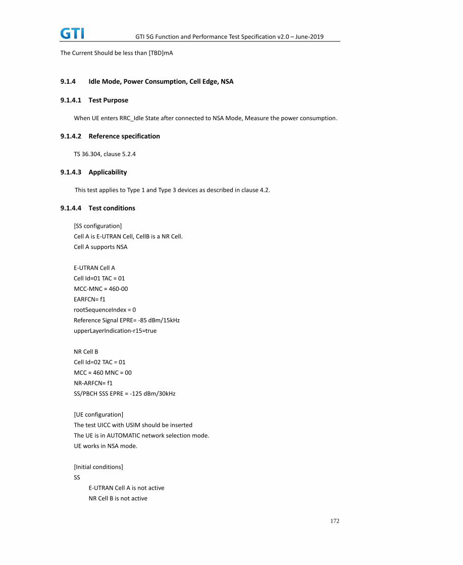
GTI 5G Function and Performance Test Specification v2.0 – June-2019
172
The Current Should be less than [TBD]mA
9.1.4 Idle Mode, Power Consumption, Cell Edge, NSA
9.1.4.1 Test Purpose
When UE enters RRC_Idle State after connected to NSA Mode, Measure the power consumption.
9.1.4.2 Reference specification
TS 36.304, clause 5.2.4
9.1.4.3 Applicability
This test applies to Type 1 and Type 3 devices as described in clause 4.2.
9.1.4.4 Test conditions
[SS configuration]
Cell A is E-UTRAN Cell, CellB is a NR Cell.
Cell A supports NSA
E-UTRAN Cell A
Cell Id=01 TAC = 01
MCC-MNC = 460-00
EARFCN= f1
rootSequenceIndex = 0
Reference Signal EPRE= -85 dBm/15kHz
upperLayerIndication-r15=true
NR Cell B
Cell Id=02 TAC = 01
MCC = 460 MNC = 00
NR-ARFCN= f1
SS/PBCH SSS EPRE = -125 dBm/30kHz
[UE configuration]
The test UICC with USIM should be inserted
The UE is in AUTOMATIC network selection mode.
UE works in NSA mode.
[Initial conditions]
SS
E-UTRAN Cell A is not active
NR Cell B is not active

GTI 5G Function and Performance Test Specification v2.0 – June-2019
173
The test shall be performed under ideal radio conditions.
UE
UE is powered off
9.1.4.5 Test procedure
Table 5.1.1.5-1: Time of cell power level and parameter changes
Time E-UTRAN Cell A NR Cell C Remark
T0 -100 -110
PREAMBLE
1. Activate E-UTRAN Cell A, NR Cell B.The SS configures the corresponding Master Information
Block and System Information Block broadcast.
2. The SS configures the initial power according to T0 in Table 9.1.4.5-1.
3. The UE is powered ON.
4. The UE performs the registration procedure with activation of the initial default EPS bearer
on Cell A (see 36.508, 4.5.2 ).
5. The SS sends an ue-CapabilityRequest including the RAT type “eutra-nr”.
6. Verify the UE sends UECapabilityInformation message including the RAT type “eutra-nr”.
7. The SS sends an RRCConnectionReconfiguration message containing NR RRCReconfiguration
message to add Cell B as NR PS-Cell with Split DRB.
8. The UE sends an RRCConnectionReconfigurationComplete message containing NR
RRCReconfigurationComplete message.
9. Verify that Data tranfer(Ping) perofrmed on NR cell B
10. The RRC connection is released by the SS. The UE enters Registered, Idle Mode
MAIN BODY
11. Wait for 3 minutes and then start power consumption tester records the changes of current
for another 3 minutes
POSTAMBLE
12. The SS initiates a Detach procedure.
13. The SS initiates a RRC release procedure.
14. Deactivate E-UTRAN Cell A and NR Cell B.
Table 5.1.1.5-2: Message Sequence
Step Message Sequence Verdict
U-S Layer Message Specific Contents
Connect the power consumption tester to
the UE
1 RRC Activate E-UTRAN Cell A and NR Cell B.
2 SS configures the initial power according to
T0 in Table 9.1.4.5-1.
3 UE Switch On UE AT Command

GTI 5G Function and Performance Test Specification v2.0 – June-2019
174
4
NAS
RRC
UE performs the registration procedure with
activation of the initial default EPS bearer on
Cell A (see 36.508, 4.5.2 ).
PASS
5 RRC The SS sends an ue-CapabilityRequest
including the RAT type “eutra-nr”.
6 RRC Verify the UE sends UECapabilityInformation
message including the RAT type “eutra-nr”.
PASS
7 NAS
RRC
SS sends an RRCConnectionReconfiguration
message containing NR RRCReconfiguration
message to add Cell B as NR PS-Cell with Split
DRB.
8 RRC UE sends an
RRCConnectionReconfigurationComplete
message containing NR
RRCReconfigurationComplete message.
PASS
9 Verify the data transmission is performed
successfully on NR Cell B.
PASS
10 RRC The RRC connection is released by the SS.
11 Wait for 3 minutes and then start power
consumption tester records the changes of
current for another 3 minutes
12
NAS SS initiates a Detach procedure. PASS
13 RRC SS initiates a RRC release procedure.
14 Deactivate E-UTRAN Cell A and NR Cell B.
9.1.4.6 9.1.4.6 Expected Result
The Current Should be less than [TBD]mA
9.1.5 Idle mode with intra Frequency Measurement, Power Consumption
9.1.5.1 Test Purpose
When UE enters idle mode and cell reselection conditions met for Intra Frequency cell check that UE
reslect into neighbour cell, Measure the power consumption.
9.1.5.2 Reference specification
TS 38.304, TS 38.331, TS 38.300
9.1.5.3 Applicability
This test applies to the device that supports SA or SA+NSA.

GTI 5G Function and Performance Test Specification v2.0 – June-2019
175
9.1.5.4 Test conditions
[SS configuration]
Cell A and B are intra frequency NR Cell.
Cell A and B supports only SA
NR Cell A
Cell Id=01 TAC = 01
MCC = 460 MNC = 00
NR Band = n41
NR-ARFCN= f1
Bandwidth = 100 MHz
SS/PBCH SSS EPRE = -125 dBm/30kHz
NR Cell B
Cell Id=02 TAC = 01
MCC = 460 MNC = 00
NR Band = n41
NR-ARFCN= f1
Bandwidth = 100 MHz
SS/PBCH SSS EPRE = -125 dBm/30kHz
[UE configuration]
The test UICC with USIM should be inserted
The UE is in AUTOMATIC network selection mode.
UE works in SA mode.
[Initial conditions]
SS
NR Cell A and NR Cell B is not active
The test shall be performed under ideal radio conditions.
UE
UE is powered off
9.1.5.5 Test procedure
Table 9.1.5.55.1.1.5-1: Time of cell power level and parameter changes
Time NR
Cell A
NR
Cell B
Remark
T0 -90 -95
T1 -106 -90 For Blind Handover

GTI 5G Function and Performance Test Specification v2.0 – June-2019
176
PREAMBLE
1. Activate NR Cell A and Cell B.The SS configures the corresponding Master Information Block
and System Information Block broadcast.
2. The SS configures the initial power according to T0 in Table 9.1.5.5-1.
3. The UE is powered ON.
4. The UE performs the registration procedure on Cell A and release the RRC connection (see
38.508, Table 4.5.2.2 till Step 20 ).
MAIN BODY
5. Start power consumption tester to record the changes of current and voltage of idle mode
6. The SS changes the power level according to T1 in Table 9.1.5.5-2
7. Initiate the paging procedure to check whether UE reselected into cell B or not
8. Get the value of power consumption tester between step 8 and 9
POSTAMBLE
9. The SS initiates a Deregitration procedure.
10. The SS initiates a RRC release procedure.
11. Deactivate NR Cell A and Cell B
Table 9.1.5.55.1.1.5-2: Message Sequence
Step Message Sequence Verdict
U-S Layer Message Specific Contents
Connect the power consumption tester to
the UE
1 RRC Activate NR Cell A.
2 SS configures the initial power according to
T0 in Table 9.1.5.5-1.
3 UE Switch On UE AT Command
4
NAS
RRC
UE performs the registration procedure (see
38.508, Table 4.5.2.2 till Step 20 ).
PASS
5 Start power consumption tester to record the
changes of current and voltage of Handover
procedure
6 The SS changes the power level according to
T1 in Table 9.1.5.5-2
7
RRC Initiate the paging procedure to check
whether UE reselected into cell B or not
PASS
8 Get the power concumption tester values at
the time of Handover between step 8 and 9
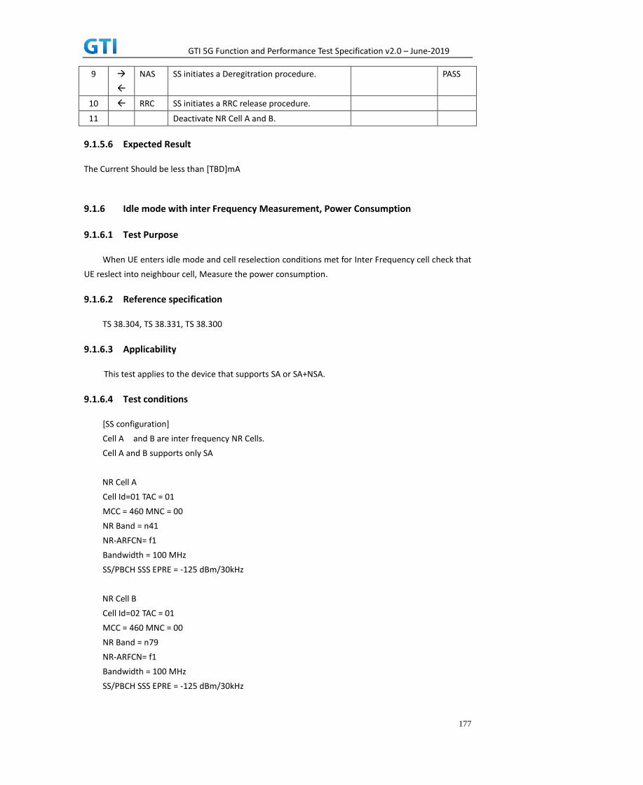
GTI 5G Function and Performance Test Specification v2.0 – June-2019
177
9
NAS SS initiates a Deregitration procedure. PASS
10 RRC SS initiates a RRC release procedure.
11 Deactivate NR Cell A and B.
9.1.5.6 Expected Result
The Current Should be less than [TBD]mA
9.1.6 Idle mode with inter Frequency Measurement, Power Consumption
9.1.6.1 Test Purpose
When UE enters idle mode and cell reselection conditions met for Inter Frequency cell check that
UE reslect into neighbour cell, Measure the power consumption.
9.1.6.2 Reference specification
TS 38.304, TS 38.331, TS 38.300
9.1.6.3 Applicability
This test applies to the device that supports SA or SA+NSA.
9.1.6.4 Test conditions
[SS configuration]
Cell A and B are inter frequency NR Cells.
Cell A and B supports only SA
NR Cell A
Cell Id=01 TAC = 01
MCC = 460 MNC = 00
NR Band = n41
NR-ARFCN= f1
Bandwidth = 100 MHz
SS/PBCH SSS EPRE = -125 dBm/30kHz
NR Cell B
Cell Id=02 TAC = 01
MCC = 460 MNC = 00
NR Band = n79
NR-ARFCN= f1
Bandwidth = 100 MHz
SS/PBCH SSS EPRE = -125 dBm/30kHz

GTI 5G Function and Performance Test Specification v2.0 – June-2019
178
[UE configuration]
The test UICC with USIM should be inserted
The UE is in AUTOMATIC network selection mode.
UE works in SA mode.
[Initial conditions]
SS
NR Cell A and NR Cell B is not active
The test shall be performed under ideal radio conditions.
UE
UE is powered off
9.1.6.5 Test procedure
Table 9.1.6.55.1.1.5-1: Time of cell power level and parameter changes
Time NR Cell A NR Cell B Remark
T0 -90 -95
T1 -106 -90 For Blind Handover
PREAMBLE
1. Activate NR Cell A and Cell B.The SS configures the corresponding Master Information Block
and System Information Block broadcast.
2. The SS configures the initial power according to T0 in Table 9.1.6.5-1.
3. The UE is powered ON.
4. The UE performs the registration procedure on Cell A and release the RRC connection (see
38.508, Table 4.5.2.2 till Step 20 ).
MAIN BODY
5. Start power consumption tester to record the changes of current and voltage of idle mode
6. The SS changes the power level according to T1 in Table 9.1.6.5-2
7. Initiate the paging procedure to check whether UE reselected into cell B or not
8. Get the value of power consumption tester between step 8 and 9
POSTAMBLE
9. The SS initiates a Deregitration procedure.
10. The SS initiates a RRC release procedure.
11. Deactivate NR Cell A and Cell B
Table 5.1.1.5-2: Message Sequence
Step Message Sequence Verdict
U-S Layer Message Specific Contents

GTI 5G Function and Performance Test Specification v2.0 – June-2019
179
Connect the power consumption tester to
the UE
1 RRC Activate NR Cell A.
2 SS configures the initial power according to
T0 in Table 9.1.6.5-1.
3 UE Switch On UE AT Command
4
NAS
RRC
UE performs the registration procedure (see
38.508, Table 4.5.2.2 till Step 20 ).
PASS
5 Start power consumption tester to record the
changes of current and voltage of Handover
procedure
6 The SS changes the power level according to
T1 in Table 9.1.6.5-2
7
RRC Initiate the paging procedure to check
whether UE reselected into cell B or not
PASS
8 Get the power concumption tester values at
the time of Handover between step 8 and 9
9
NAS SS initiates a Deregitration procedure. PASS
10 RRC SS initiates a RRC release procedure.
11 Deactivate NR Cell A and B.
9.1.6.6 Expected Result
The Current Should be less than [TBD]mA
9.2 RRC Connection mode
9.2.1 Connected Mode, Power Consumption
9.2.1.1 Connected Mode, Power Consumption, SA
9.2.1.1.1 Test Purpose
When UE is in RRC Connected State after Registering in NR cell, Measure the power
consumption.
9.2.1.1.2 Reference specification
TS 38.304, TS 38.331, TS 38.300
9.2.1.1.3 Applicability
This test applies to the device that supports SA or SA+NSA.

GTI 5G Function and Performance Test Specification v2.0 – June-2019
180
9.2.1.1.4 Test conditions
[SS configuration]
Cell A is a NR Cell.
Cell A supports only SA
NR Cell A
Cell Id=01 TAC = 01
MCC = 460 MNC = 00
NR-ARFCN= f1
SS/PBCH SSS EPRE = -125 dBm/30kHz
[UE configuration]
The test UICC with USIM should be inserted
The UE is in AUTOMATIC network selection mode.
UE works in SA mode.
[Initial conditions]
SS
NR Cell A is not active
The test shall be performed under ideal radio conditions.
UE
UE is powered off
9.2.1.1.5 Test procedure
Table 5.1.1.5-1: Time of cell power level and parameter changes
Time NR Cell A Remark
T0 -90
PREAMBLE
1. Activate NR Cell A.The SS configures the corresponding Master Information Block and System
Information Block broadcast.
2. The SS configures the initial power according to T0 in Table 9.2.1.5-1.
3. The UE is powered ON.
4. The UE performs the registration procedure on Cell A (see 38.508, Table 4.5.2.2 till Step 18 ).
5. Verify that Data tranfer(Ping) perofrmed on NR cell A
MAIN BODY
6. Wait for 3 minutes and then start power consumption tester records the changes of current
and voltage for another 3 minutes
POSTAMBLE

GTI 5G Function and Performance Test Specification v2.0 – June-2019
181
7. The SS initiates a Deregitration procedure.
8. The SS initiates a RRC release procedure.
9. Deactivate NR Cell A.
Table 5.1.1.5-2: Message Sequence
Step Message Sequence Verdict
U-S Layer Message Specific Contents
Connect the power consumption tester to
the UE
1 RRC Activate NR Cell A.
2 SS configures the initial power according to
T0 in Table 9.2.1.5-1.
3 UE Switch On UE AT Command
4
NAS
RRC
UE performs the registration procedure (see
38.508, Table 4.5.2.2 till Step 18 ).
PASS
5 Verify the data transmission is performed
successfully on NR Cell A.
PASS
6 Wait for 3 minutes and then start power
consumption tester records the changes of
current and voltage for another 3 minutes
7
NAS SS initiates a Deregistration procedure. PASS
8 RRC SS initiates a RRC release procedure.
9 Deactivate NR Cell A.
9.2.1.1.6 Expected Result
The Current Should be less than [TBD]mA
9.2.1.2 Connected Mode with DRX, Power Consumption, SA
9.2.1.2.1 Test Purpose
When UE is in RRC Connected State after Registering in NR cell, measure the power consumption
with DRX on.
9.2.1.2.2 Reference specification
TS 38.304, TS 38.331, TS 38.300
9.2.1.2.3 Applicability
This test applies to Type 1 and Type 2 devices as described in clause 4.2
9.2.1.2.4 Test conditions
[SS configuration]
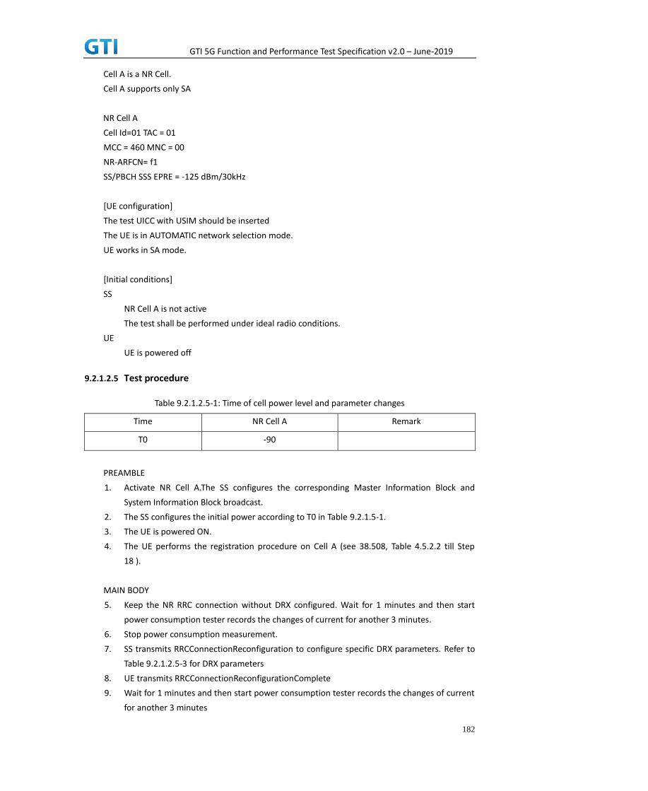
GTI 5G Function and Performance Test Specification v2.0 – June-2019
182
Cell A is a NR Cell.
Cell A supports only SA
NR Cell A
Cell Id=01 TAC = 01
MCC = 460 MNC = 00
NR-ARFCN= f1
SS/PBCH SSS EPRE = -125 dBm/30kHz
[UE configuration]
The test UICC with USIM should be inserted
The UE is in AUTOMATIC network selection mode.
UE works in SA mode.
[Initial conditions]
SS
NR Cell A is not active
The test shall be performed under ideal radio conditions.
UE
UE is powered off
9.2.1.2.5 Test procedure
Table 9.2.1.2.5-1: Time of cell power level and parameter changes
Time NR Cell A Remark
T0 -90
PREAMBLE
1. Activate NR Cell A.The SS configures the corresponding Master Information Block and
System Information Block broadcast.
2. The SS configures the initial power according to T0 in Table 9.2.1.5-1.
3. The UE is powered ON.
4. The UE performs the registration procedure on Cell A (see 38.508, Table 4.5.2.2 till Step
18 ).
MAIN BODY
5. Keep the NR RRC connection without DRX configured. Wait for 1 minutes and then start
power consumption tester records the changes of current for another 3 minutes.
6. Stop power consumption measurement.
7. SS transmits RRCConnectionReconfiguration to configure specific DRX parameters. Refer to
Table 9.2.1.2.5-3 for DRX parameters
8. UE transmits RRCConnectionReconfigurationComplete
9. Wait for 1 minutes and then start power consumption tester records the changes of current
for another 3 minutes

GTI 5G Function and Performance Test Specification v2.0 – June-2019
183
10. Stop power consumption measurement.
POSTAMBLE
11. The SS initiates a Deregitration procedure.
12. The SS initiates a RRC release procedure.
13. Deactivate NR Cell A.
Table 9.2.1.2.5-2: Message Sequence
Step Message Sequence Verdict
U-S Layer Message Specific Contents
1 RRC Activate NR Cell A.
2 SS configures the initial power according to
T0 in Table 9.2.1.5-1.
3 UE Switch On UE AT Command
4
NAS
RRC
UE performs the registration procedure (see
38.508, Table 4.5.2.2 till Step 18 ).
PASS
5 Wait for 1 minutes and then start power
consumption tester records the changes of
current for another 3 minutes
Without DRX PASS
6 Stop power consumption measurement.
7 NAS
RRC
SS transmits RRCConnectionReconfiguration
to configure specific DRX parameters.
Table 9.2.1.2.5-3 for
DRX parameters
8 NAS
RRC
UE transmits
RRCConnectionReconfigurationComplete
PASS
9 Wait for 1 minutes and then start power
consumption tester records the changes of
current for another 3 minutes
PASS
10 Stop power consumption measurement.
11
NAS SS initiates a Deregistration procedure.
12 RRC SS initiates a RRC release procedure.
13 Deactivate NR Cell A.
Table 9.2.1.2.5-3: NR DRX Parameters in step 7
Derivation Path: TS 38.331 [6], clause 6.3.2
Information Element Value/remark Comment
DRX-Config ::= SEQUENCE {
drx-onDurationTimer CHOICE {
milliSeconds ms10
}
drx-InactivityTimer [ms60]
drx-HARQ-RTT-TimerDL [14]
drx-HARQ-RTT-TimerUL [14]

GTI 5G Function and Performance Test Specification v2.0 – June-2019
184
drx-RetransmissionTimerDL [sl 8]
drx-RetransmissionTimerUL [sl 8]
drx-LongCycleStartOffset CHOICE {
ms160 0
}
shortDRX not present
drx-SlotOffset 0
}
9.2.1.2.6 Expected Result
Record the average current in step 5 (current without DRX) and step 9 (current with DRX). The
Current with DRX should be less than the current without DRX.
Table 9.2.1.2.6-1: Test Results
Test Step Average Current(mA)
Step 5: without DRX
Step 9: with DRX
9.2.1.3 Connected Mode with DRX on SCG, Power Consumption, NSA
9.2.1.3.1 Test Purpose
When UE is in RRC Connected State after Registering in E-UTRAN and NR cell, measure the power
consumption with DRX configured on SCG cell.
9.2.1.3.2 Reference specification
TS 38.304, TS 38.331, TS 38.300
9.2.1.3.3 Applicability
This test applies to Type 1 and Type 3 devices as described in clause 4.2
9.2.1.3.4 Test conditions
[SS configuration]
Cell A is E-UTRAN Cell, CellB is a NR Cell.
Cell A supports NSA
E-UTRAN Cell A
Cell Id=01 TAC = 01
MCC-MNC = 460-00
EARFCN= f1
rootSequenceIndex = 0
Reference Signal EPRE= -85 dBm/15kHz
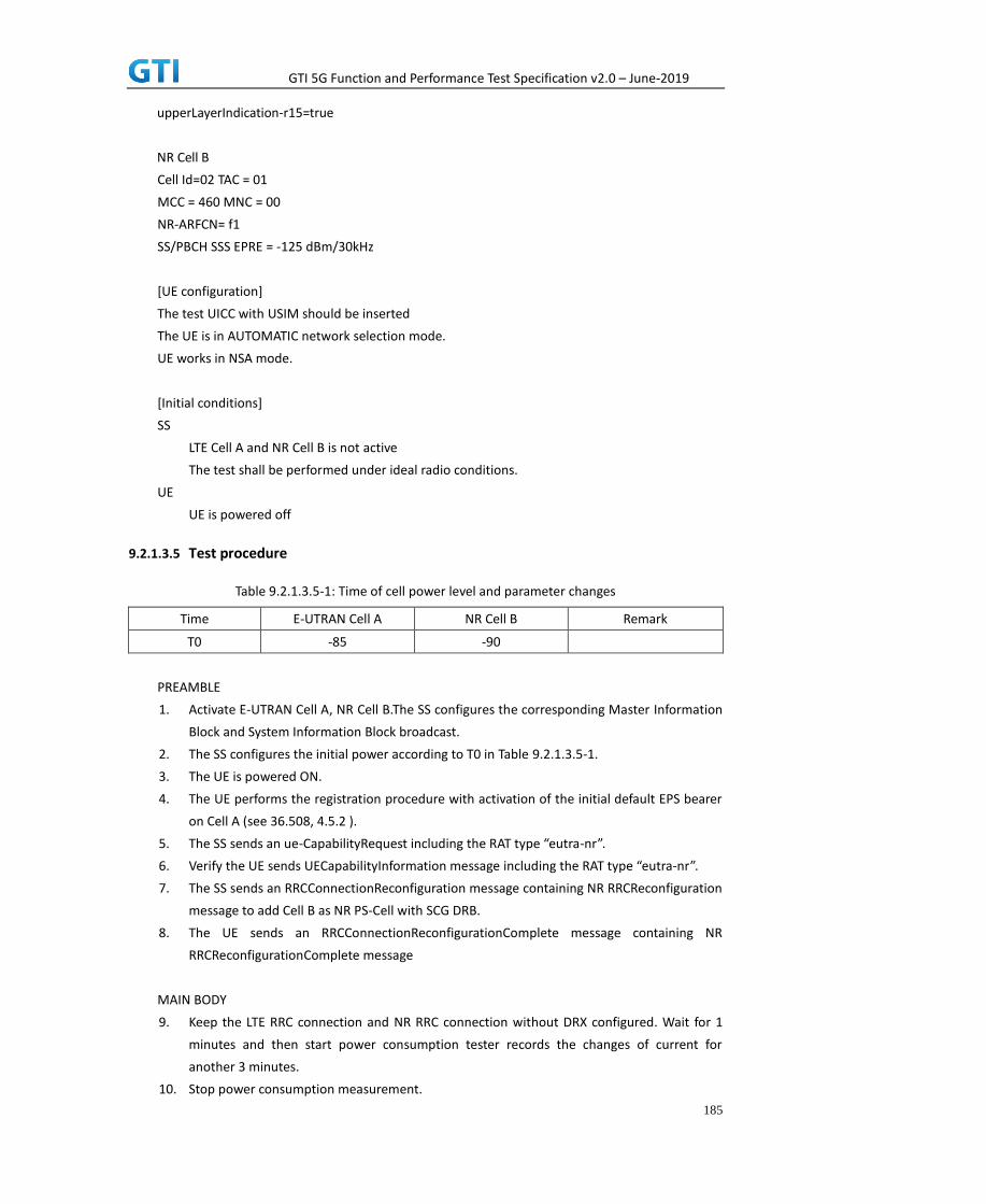
GTI 5G Function and Performance Test Specification v2.0 – June-2019
185
upperLayerIndication-r15=true
NR Cell B
Cell Id=02 TAC = 01
MCC = 460 MNC = 00
NR-ARFCN= f1
SS/PBCH SSS EPRE = -125 dBm/30kHz
[UE configuration]
The test UICC with USIM should be inserted
The UE is in AUTOMATIC network selection mode.
UE works in NSA mode.
[Initial conditions]
SS
LTE Cell A and NR Cell B is not active
The test shall be performed under ideal radio conditions.
UE
UE is powered off
9.2.1.3.5 Test procedure
Table 9.2.1.3.5-1: Time of cell power level and parameter changes
Time E-UTRAN Cell A NR Cell B Remark
T0 -85 -90
PREAMBLE
1. Activate E-UTRAN Cell A, NR Cell B.The SS configures the corresponding Master Information
Block and System Information Block broadcast.
2. The SS configures the initial power according to T0 in Table 9.2.1.3.5-1.
3. The UE is powered ON.
4. The UE performs the registration procedure with activation of the initial default EPS bearer
on Cell A (see 36.508, 4.5.2 ).
5. The SS sends an ue-CapabilityRequest including the RAT type “eutra-nr”.
6. Verify the UE sends UECapabilityInformation message including the RAT type “eutra-nr”.
7. The SS sends an RRCConnectionReconfiguration message containing NR RRCReconfiguration
message to add Cell B as NR PS-Cell with SCG DRB.
8. The UE sends an RRCConnectionReconfigurationComplete message containing NR
RRCReconfigurationComplete message
MAIN BODY
9. Keep the LTE RRC connection and NR RRC connection without DRX configured. Wait for 1
minutes and then start power consumption tester records the changes of current for
another 3 minutes.
10. Stop power consumption measurement.

GTI 5G Function and Performance Test Specification v2.0 – June-2019
186
11. SS transmits RRCConnectionReconfiguration to configure specific DRX parameters on SCG
NR Cell B. The DRX parameters are the same as in Table 9.2.1.2.5-3
12. UE transmits RRCConnectionReconfigurationComplete
13. Wait for 1 minutes and then start power consumption tester records the changes of current
for another 3 minutes
14. Stop power consumption measurement.
POSTAMBLE
15. The SS initiates a Deregitration procedure.
16. The SS initiates a RRC release procedure.
17. Deactivate E-UTRAN Cell A and NR Cell B.
Table 9.2.1.3.5-2: Message Sequence
Step Message Sequence Verdict
U-S Layer Message Specific Contents
1 RRC Activate E-UTRAN Cell A and NR Cell B.
2 SS configures the initial power according to
T0 in Table 9.2.1.3.5-1.
3 UE Switch On UE AT Command
4
NAS
RRC
UE performs the registration procedure with
activation of the initial default EPS bearer on
Cell A (see 36.508, 4.5.2 ).
PASS
5 RRC The SS sends an ue-CapabilityRequest
including the RAT type “eutra-nr”.
6 RRC Verify the UE sends UECapabilityInformation
message including the RAT type “eutra-nr”.
PASS
7 NAS
RRC
SS sends an RRCConnectionReconfiguration
message containing NR RRCReconfiguration
message to add Cell B as NR PS-Cell with SCG
DRB.
8 RRC UE sends an
RRCConnectionReconfigurationComplete
message containing NR
RRCReconfigurationComplete message.
PASS
9 Wait for 1 minutes and then start power
consumption tester records the changes of
current for another 3 minutes
Without DRX PASS
10 Stop power consumption measurement.
11 NAS
RRC
SS transmits RRCConnectionReconfiguration
to configure specific DRX parameters.
Table 9.2.1.2.5-3 for
DRX parameters
12 NAS
RRC
UE transmits
RRCConnectionReconfigurationComplete
PASS
13 Wait for 1 minutes and then start power PASS

GTI 5G Function and Performance Test Specification v2.0 – June-2019
187
consumption tester records the changes of
current for another 3 minutes
14 Stop power consumption measurement.
15
NAS SS initiates a Deregistration procedure.
16 RRC SS initiates a RRC release procedure.
17 Deactivate E-UTRAN Cell A and NR Cell B.
9.2.1.3.6 Expected Result
Record the average current in step 9 (current without DRX) and step 13 (current with DRX on
SCG). The Current with DRX on SCG should be less than the current without DRX.
Table 9.2.1.3.6-1: Test Results
Test Step Average Current(mA)
Step 9: without DRX
Step 13: with DRX on SCG
9.2.1.4 Connected Mode with DRX on MCG and SCG, Power Consumption, NSA
9.2.1.4.1 Test Purpose
When UE is in RRC Connected State after Registering in E-UTRAN and NR cell, measure the power
consumption with DRX configured on both MCG and SCG cell.
9.2.1.4.2 Reference specification
TS 38.304, TS 38.331, TS 38.300
9.2.1.4.3 Applicability
This test applies to Type 1 and Type 3 devices as described in clause 4.2
9.2.1.4.4 Test conditions
The same as in 9.2.1.3.4
9.2.1.4.5 Test procedure
The same as in 9.2.1.3.5 except step 11 . Step 11 is changed as following
“ 11. SS transmits RRCConnectionReconfiguration to configure specific DRX parameters on MCG
E-UTRAN Cell A and SCG NR Cell B. Refer to Table 9.2.1.4.59.2.1.2.5-1 for E-UTRAN DRX parameters for
MCG and Table 9.2.1.4.59.2.1.2.5-2 for NR DRX parameters for SCG”
Table 9.2.1.4.5-1: E-UTRAN DRX Parameters for MCG
Derivation Path: TS 36.331, clause 6.3.2

GTI 5G Function and Performance Test Specification v2.0 – June-2019
188
Information Element Value/remark Comment
drx-Config CHOICE {
setup SEQUENCE {
onDurationTimer psf8
}
drx-InactivityTimer psf60
drx-RetransmissionTimer psf4
longDRX-CycleStartOffset CHOICE {
sf160 0
}
shortDRX Not present
}
}
Table 9.2.1.4.5-2: NR DRX Parameters for SCG
Derivation Path: TS 38.331 [6], clause 6.3.2
Information Element Value/remark Comment
DRX-Config ::= SEQUENCE {
drx-onDurationTimer CHOICE {
milliSeconds ms10
}
drx-InactivityTimer [ms60]
drx-HARQ-RTT-TimerDL [14]
drx-HARQ-RTT-TimerUL [14]
drx-RetransmissionTimerDL [sl 8]
drx-RetransmissionTimerUL [sl 8]
drx-LongCycleStartOffset CHOICE {
ms160 0
}
shortDRX not present
drx-SlotOffset 0
}
9.2.1.4.6 Expected Result
Record the average current in step 9 (current without DRX) and step 13 (current with DRX on
MCG and SCG). The Current with DRX on SCG should be less than the current without DRX.
Table 9.2.1.3.6-1: Test Results
Test Step Average Current(mA)
Step 9: without DRX
Step 13: with DRX on MCG and SCG

GTI 5G Function and Performance Test Specification v2.0 – June-2019
189
9.2.2 Inter Frequency Handover, Power Consumption, LTE to LTE
9.2.2.1 Test Purpose
The UE Executes the handovers between Inter-Frequency LTE cells for many times with
contention based random access procedure and verify the power consumption.
9.2.2.2 Reference specification
TS 36.300, TS 36.331, TS 38.300
9.2.2.3 Applicability
This test applies to the device that supports NSA or SA+NSA.
9.2.2.4 Test conditions
[SS configuration]
Cell A and CellB are E-UTRAN Cells, CellC is a NR Cell.
Cell A supports NSA
E-UTRAN Cell A
Cell Id=01 TAC = 01
MCC-MNC = 460-00
EARFCN= f1
rootSequenceIndex = 0
Reference Signal EPRE= -85 dBm/15kHz
upperLayerIndication-r15=true
E-UTRAN Cell B
Cell Id=02 TAC = 02
MCC-MNC = 460-00
EARFCN= f2
rootSequenceIndex = 22
Reference Signal EPRE= -125 dBm/15kHz
upperLayerIndication-r15=true
NR Cell C
Cell Id=03 TAC = 01
MCC = 460 MNC = 00
NR-ARFCN= f1
SS/PBCH SSS EPRE = -125 dBm/30kHz
[UE configuration]
The test UICC with USIM should be inserted
The UE is in AUTOMATIC network selection mode.

GTI 5G Function and Performance Test Specification v2.0 – June-2019
190
UE works in NSA mode.
[Initial conditions]
SS
E-UTRAN Cell A and Cell B are not active
NR Cell C is not active
The test shall be performed under ideal radio conditions.
UE
UE is powered off
9.2.2.5 Test procedure
Table 5.1.1.5-1: Time of cell power level and parameter changes
Time E-UTRAN
Cell A
E-UTRAN
Cell B
NR
Cell C
Remark
T0 -85 -infinity -90 Cell B shall be off
T1 -91 -85 -90 Cell B better than Cell
A
T2 -85 -91 -90 Cell A better than Cell
B
PREAMBLE
1. Activate E-UTRAN Cell A, NR Cell C.The SS configures the corresponding Master Information
Block and System Information Block broadcast.
2. The SS configures the initial power according to T0 in Table 9.2.4.5-1.
3. The UE is powered ON.
4. The UE performs the registration procedure with activation of the initial default EPS bearer
on Cell A (see 36.508, 4.5.2 ).
5. The SS sends an ue-CapabilityRequest including the RAT type “eutra-nr”.
6. Verify the UE sends UECapabilityInformation message including the RAT type “eutra-nr”.
7. The SS sends an RRCConnectionReconfiguration message containing NR RRCReconfiguration
message to add Cell C as NR PS-Cell with Split DRB.
8. The UE sends an RRCConnectionReconfigurationComplete message containing NR
RRCReconfigurationComplete message.
9. Verify that Data tranfer(Ping) perofrmed on NR cell C
MAIN BODY
10. The SS initiate the RRCConnectionReconfiguration procedure to configure the A4
measurement event to measure cell B
11. The SS changes the power levels according to T1 in Table 9.2.4.5-1.

GTI 5G Function and Performance Test Specification v2.0 – June-2019
191
12. The UE perrforms measurements on Cell B and provides measurement reports (Event A4) to
SS
13. The SS initiates the handover procedure to Cell B with adding and releasing same PS-Cell(NR
Cell C) and RRCConnectionReconfiguration doesn’t contain a dedicated PRACH preamble to
make Contention based RACH procedure in cell B
14. The UE completes the Handover in Cell B by sending RRCConnectionReconfiguration
Complete to the SS
15. Measure the minimum, maximum, average power consumption during the random access
procedure between step 13 and 14.
16. Verify that Data transfer(Ping) performed on NR Cell C
17. The SS initiate the RRCConnectionReconfiguration procedure to configure the A4
measurement event to measure cell A
18. The SS changes the power levels according to T2 in Table 9.2.4.5-1
19. The UE perrforms measurements on Cell A and provides measurement reports (Event A4) to
SS
20. The SS initiates the handover procedure to Cell A with adding and releasing same PS-Cell(NR
Cell C) and RRCConnectionReconfiguration doesn’t contain a dedicated PRACH preamble to
make Contention based RACH procedure in cell A
21. The UE completes the Handover in Cell A by sending RRCConnectionReconfiguration
Complete to the SS
22. Measure the minimum, maximum, average power consumption during the random access
procedure between step 20 and 21.
23. Verify that Data transfer(Ping) performed on NR Cell C
24. Get the value of power consumption tester and calulate the power consumption
25. The handover procedure between 10 to 24 are repeated for four times
26. Calculate the overall minimum, maximum and average power consumption values
POSTAMBLE
27. The SS initiates a Detach procedure.
28. The SS initiates a RRC release procedure.
29. Deactivate E-UTRAN Cell A, Cell B and NR Cell C.
Table 9.2.2.55.1.1.5-2: Message Sequence
Step Message Sequence Verdict
U-S Layer Message Specific Contents
Connect the power consumption tester to
the UE
1 RRC Activate E-UTRAN Cell A, Cell B and NR Cell C.
2 SS configures the initial power according to
T0 in Table 9.2.4.5-1.
3 UE Switch On UE AT Command
4
NAS
RRC
UE performs the registration procedure with
activation of the initial default EPS bearer on
Cell A (see 36.508, 4.5.2 ).
PASS

GTI 5G Function and Performance Test Specification v2.0 – June-2019
192
5 RRC The SS sends an ue-CapabilityRequest
including the RAT type “eutra-nr”.
6 RRC Verify the UE sends UECapabilityInformation
message including the RAT type “eutra-nr”.
PASS
7 NAS
RRC
SS sends an RRCConnectionReconfiguration
message containing NR RRCReconfiguration
message to add Cell B as NR PS-Cell with Split
DRB.
8 RRC UE sends an
RRCConnectionReconfigurationComplete
message containing NR
RRCReconfigurationComplete message.
PASS
9 Verify the data transmission is performed
successfully on NR Cell C.
PASS
10
RRC RRC Connection Reconfiguration procedure
to UE to configure the measurement Event
for Cell B
11 TX Power modification according to step T1
in table 9.2.4.5-1
12 RRC Measurement Report (Event A4) PASS
13 RRC RRC Connection Reconfiguration to the UE to
Handover to Cell B
14 RRC UE inititates RACH procedure in Cell B and
send RRC Connection Reconfiguration
complete to SS
PASS
15 Get the maximum, minimum and average
power consumption during the random
access procedure between step 13 and 14
16 Verify the data transmission is performed
successfully on NR Cell C.
PASS
17
RRC RRC Connection Reconfiguration procedure
to UE to configure the measurement Event
for Cell A
18 TX Power modification according to step T2
in table 9.2.4.5-1
19 RRC Measurement Report (Event A4) PASS
20 RRC RRC Connection Reconfiguration to the UE to
Handover to Cell A
21 RRC UE inititates RACH procedure in Cell A and
send RRC Connection Reconfiguration
complete to SS
PASS
22 Get the maximum, minimum and average
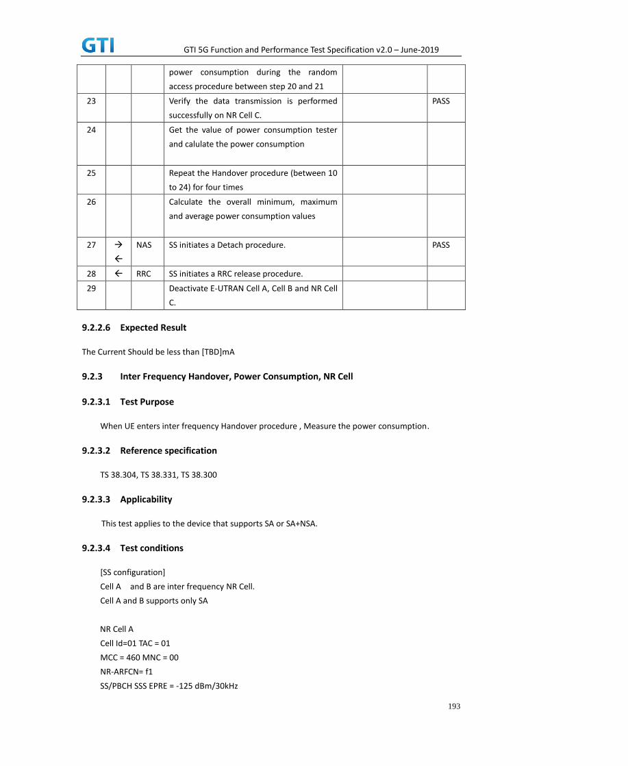
GTI 5G Function and Performance Test Specification v2.0 – June-2019
193
power consumption during the random
access procedure between step 20 and 21
23 Verify the data transmission is performed
successfully on NR Cell C.
PASS
24 Get the value of power consumption tester
and calulate the power consumption
25 Repeat the Handover procedure (between 10
to 24) for four times
26 Calculate the overall minimum, maximum
and average power consumption values
27
NAS SS initiates a Detach procedure. PASS
28 RRC SS initiates a RRC release procedure.
29 Deactivate E-UTRAN Cell A, Cell B and NR Cell
C.
9.2.2.6 Expected Result
The Current Should be less than [TBD]mA
9.2.3 Inter Frequency Handover, Power Consumption, NR Cell
9.2.3.1 Test Purpose
When UE enters inter frequency Handover procedure , Measure the power consumption.
9.2.3.2 Reference specification
TS 38.304, TS 38.331, TS 38.300
9.2.3.3 Applicability
This test applies to the device that supports SA or SA+NSA.
9.2.3.4 Test conditions
[SS configuration]
Cell A and B are inter frequency NR Cell.
Cell A and B supports only SA
NR Cell A
Cell Id=01 TAC = 01
MCC = 460 MNC = 00
NR-ARFCN= f1
SS/PBCH SSS EPRE = -125 dBm/30kHz

GTI 5G Function and Performance Test Specification v2.0 – June-2019
194
NR Cell B
Cell Id=02 TAC = 01
MCC = 460 MNC = 00
NR-ARFCN= f1
SS/PBCH SSS EPRE = -125 dBm/30kHz
[UE configuration]
The test UICC with USIM should be inserted
The UE is in AUTOMATIC network selection mode.
UE works in SA mode.
[Initial conditions]
SS
NR Cell A is not active
The test shall be performed under ideal radio conditions.
UE
UE is powered off
9.2.3.5 Test procedure
Table 5.1.1.5-1: Time of cell power level and parameter changes
Time NR
Cell A
NR
Cell B
Remark
T0 -90 -95
T1 -106 -90 For Blind Handover
PREAMBLE
1. Activate NR Cell A and Cell B.The SS configures the corresponding Master Information Block
and System Information Block broadcast.
2. The SS configures the initial power according to T0 in Table 9.2.5.5-1.
3. The UE is powered ON.
4. The UE performs the registration procedure on Cell A (see 38.508, Table 4.5.2.2 till Step 18 ).
5. Verify that Data tranfer(Ping) perofrmed on NR cell A.
6. SS reconfigures the cell power level according to T1 in Table 9.2.5.5-1
MAIN BODY
7. Start power consumption tester to record the changes of current and voltage of Handover
procedure.
8. The SS Send RRC Reconfiguration message to make Handover from Cell A to Cell B

GTI 5G Function and Performance Test Specification v2.0 – June-2019
195
9. Verify that RACH procedure is successful and UE send RRC Reconfiguration complete in Cell B
10. Get the value of power consumption tester between step 8 and 9
11. The SS Send RRC Reconfiguration message to make Handover from Cell B to Cell A
12. Verify that RACH procedure is successful and UE send RRC Reconfiguration complete in Cell
A
13. Get the value of power consumption tester between step 11 and 12
14. Repeat Step 8 to 13 for four times and calculate the overall average power consumption at
the time of Handover procedure
POSTAMBLE
15. The SS initiates a Deregitration procedure.
16. The SS initiates a RRC release procedure.
17. Deactivate NR Cell A.
Table 5.1.1.5-2: Message Sequence
Step Message Sequence Verdict
U-S Layer Message Specific Contents
Connect the power consumption tester to
the UE
1 RRC Activate NR Cell A.
2 SS configures the initial power according to
T0 in Table 9.2.5.5-1.
3 UE Switch On UE AT Command
4
NAS
RRC
UE performs the registration procedure (see
38.508, Table 4.5.2.2 till Step 18 ).
PASS
5 Verify the data transmission is performed
successfully on NR Cell A.
PASS
6 SS reconfigures the cell power level according
to T1 in Table 9.2.5.5-1
7 Start power consumption tester to record the
changes of current and voltage of Handover
procedure
8 RRC The SS sends RRC Reconfiguration message
to make Handover from Cell A to Cell B
9 RRC UE sends RRC Reconfiguration complete in
Cell B
PASS
10 Get the power concumption tester values at
the time of Handover between step 8 and 9
11 RRC The SS sends RRC Reconfiguration message
to make Handover from Cell B to Cell A
PASS
12 RRC UE sends RRC Reconfiguration complete in
Cell A
13 Get the power concumption tester values at
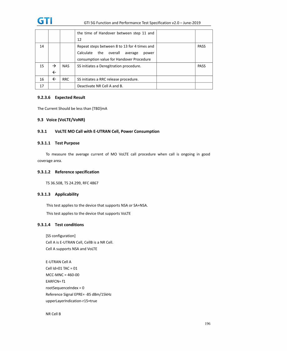
GTI 5G Function and Performance Test Specification v2.0 – June-2019
196
the time of Handover between step 11 and
12
14 Repeat steps between 8 to 13 for 4 times and
Calculate the overall average power
consumption value for Handover Procedure
PASS
15
NAS SS initiates a Deregitration procedure. PASS
16 RRC SS initiates a RRC release procedure.
17 Deactivate NR Cell A and B.
9.2.3.6 Expected Result
The Current Should be less than [TBD]mA
9.3 Voice (VoLTE/VoNR)
9.3.1 VoLTE MO Call with E-UTRAN Cell, Power Consumption
9.3.1.1 Test Purpose
To measure the average current of MO VoLTE call procedure when call is ongoing in good
coverage area.
9.3.1.2 Reference specification
TS 36.508, TS 24.299, RFC 4867
9.3.1.3 Applicability
This test applies to the device that supports NSA or SA+NSA.
This test applies to the device that supports VoLTE
9.3.1.4 Test conditions
[SS configuration]
Cell A is E-UTRAN Cell, CellB is a NR Cell.
Cell A supports NSA and VoLTE
E-UTRAN Cell A
Cell Id=01 TAC = 01
MCC-MNC = 460-00
EARFCN= f1
rootSequenceIndex = 0
Reference Signal EPRE= -85 dBm/15kHz
upperLayerIndication-r15=true
NR Cell B

GTI 5G Function and Performance Test Specification v2.0 – June-2019
197
Cell Id=02 TAC = 01
MCC = 460 MNC = 00
NR-ARFCN= f1
SS/PBCH SSS EPRE = -125 dBm/30kHz
[UE configuration]
The test UICC with USIM should be inserted
The UE is in AUTOMATIC network selection mode.
UE works in NSA mode.
IMS VoLTE Feature should be enabled on DUT
[Initial conditions]
SS
E-UTRAN Cell A is not active
NR Cell B is not active
The test shall be performed under ideal radio conditions.
UE
UE is powered off
9.3.1.5 Test procedure
Table 5.1.1.5-1: Time of cell power level and parameter changes
Time E-UTRAN Cell A NR Cell C Remark
T0 -85 -90
PREAMBLE
1. Activate E-UTRAN Cell A, NR Cell B.The SS configures the corresponding Master Information
Block and System Information Block broadcast.
2. The SS configures the initial power according to T0 in Table 9.3.1.5-1.
3. The UE is powered ON.
4. The UE performs the registration procedure with activation of the initial default EPS bearer
on Cell A (see 36.508, 4.5.2 ).
5. The SS sends an ue-CapabilityRequest including the RAT type “eutra-nr”.
6. Verify the UE sends UECapabilityInformation message including the RAT type “eutra-nr”.
7. The SS sends an RRCConnectionReconfiguration message containing NR RRCReconfiguration
message to add Cell B as NR PS-Cell with Split DRB.
8. The UE sends an RRCConnectionReconfigurationComplete message containing NR
RRCReconfigurationComplete message.
9. UE inititaes the PDN connectivity procedure for the IMS PDN and Default EPS procedure for
IMS PDN is completed in Cell A.
10. IMS Registration is successful in Cell A
11. Verify that Data tranfer(Ping) perofrmed on NR cell B
MAIN BODY

GTI 5G Function and Performance Test Specification v2.0 – June-2019
198
12. start power consumption tester records the changes of current and voltage and start the MO
VoLTE call
13. Verify the RTP packet flow between UE and SS in both directions and stop the VoLTE call
after 3 minutes
14. Stop the power consumption measurement and calculate the average current for VoLTE call
POSTAMBLE
15. The SS initiates a Detach procedure.
16. The SS initiates a RRC release procedure.
17. Deactivate E-UTRAN Cell A and NR Cell B.
Table 5.1.1.5-2: Message Sequence
Step Message Sequence Verdict
U-S Layer Message Specific Contents
Connect the power consumption tester to
the UE
1 RRC Activate E-UTRAN Cell A and NR Cell B.
2 SS configures the initial power according to
T0 in Table 9.3.1.5-1.
3 UE Switch On UE AT Command
4
NAS
RRC
UE performs the registration procedure with
activation of the initial default EPS bearer on
Cell A (see 36.508, 4.5.2 ).
PASS
5 RRC The SS sends an ue-CapabilityRequest
including the RAT type “eutra-nr”.
6 RRC Verify the UE sends UECapabilityInformation
message including the RAT type “eutra-nr”.
PASS
7 NAS
RRC
SS sends an RRCConnectionReconfiguration
message containing NR RRCReconfiguration
message to add Cell B as NR PS-Cell with Split
DRB.
8 RRC UE sends an
RRCConnectionReconfigurationComplete
message containing NR
RRCReconfigurationComplete message.
PASS
9
UE initiates the PDN Connectivity Procedure
for IMS PDN
10
IMS Registration Procedure is successful in
Cell A
PASS
11 Verify the data transmission is performed
successfully on NR Cell B.
PASS
12
Start the power consumption recorder for
current measurements and Start MO VoLTE

GTI 5G Function and Performance Test Specification v2.0 – June-2019
199
call
13 Verify the RTP packet flow between UE and
SS and stop the VolTE call after 3 minutes
PASS
14 Stop the power consumption and calculte the
average current of the VoLTE call
15
NAS SS initiates a Detach procedure. PASS
16 RRC SS initiates a RRC release procedure.
17 Deactivate E-UTRAN Cell A and NR Cell B.
9.3.1.6 Expected Result
Record the test results of the current
9.3.2 VoNR MO call, Power Consumption
9.3.2.1 Test Purpose
To measure the average current of VoNR call for the MO call
9.3.2.2 Reference specification
TS 38.304, TS 38.331, TS 38.300
9.3.2.3 Applicability
This test applies to the device that supports SA or SA+NSA.
9.3.2.4 Test conditions
[SS configuration]
Cell A is a NR Cell.
Cell A supports only SA
NR Cell A
Cell Id=01 TAC = 01
MCC = 460 MNC = 00
NR Band = n41
NR-ARFCN= f1
Bandwidth = 100 MHz
SS/PBCH SSS EPRE = -125 dBm/30kHz
PDN = IMS PDN
[UE configuration]
The test UICC with USIM should be inserted
The UE is in AUTOMATIC network selection mode.
UE works in SA mode.

GTI 5G Function and Performance Test Specification v2.0 – June-2019
200
[Initial conditions]
SS
NR Cell A is not active
The test shall be performed under ideal radio conditions.
UE
UE is powered off
9.3.2.5 Test procedure
Table 5.1.1.5-1: Time of cell power level and parameter changes
Time NR
Cell A
Remark
T0 -75
PREAMBLE
1. Activate NR Cell A.The SS configures the corresponding Master Information Block and System
Information Block broadcast.
2. The SS configures the initial power according to T0 in Table 9.3.2.5-1.
3. The UE is powered ON.
4. The UE performs the registration procedure on Cell A (see 38.508, Table 4.5.2.2-2 till Step
18 ).
5. UE sends REGISTER message
6. SS responds to REGISTER with 401 Unauthorized
7. UE sends REGISTER again with proper IPSec settings and SS responds with 200 OK
8. UE sends SUBSCRIBE message and the SS responds with with 200 OK
9. SS sends NOTIFY. The UE responds NOTIFY with 200 OK
MAIN BODY
10. Start the power consumption tester and initiate the MO IMS call
11. UE sends INVITE Request
12. SS transmits 100 Trying and 183 Session Progress
13. UE sends PRACK and SS responds with 200 OK
14. SS transmits PDU session establishment request for voice call
15. UE sends PDU session establishment accept
16. SS transmits 180 ringing and 200 OK for INVITE
17. UE sends ACK for 200 OK
18. Verify if RTP packets are ongoing to confirm successful call progress and keep the call active
for 3 minutes
19. Stop the power consumption measurement and note down the current values
20. UE initiates the call release procedure

GTI 5G Function and Performance Test Specification v2.0 – June-2019
201
POSTAMBLE
21. The SS initiates a Deregitration procedure.
22. The SS initiates a RRC release procedure.
23. Deactivate NR Cell A.
Table 5.1.1.5-2: Message Sequence
Step Message Sequence Verdict
U-S Layer Message Specific Contents
Connect the power consumption tester to
the UE
1 RRC Activate NR Cell A.
2 SS configures the initial power according to
T0 in Table 9.3.2.5-1.
3 UE Switch On UE AT Command
4
NAS
RRC
UE performs the registration procedure (see
38.508, Table 4.5.2.2-2 till Step 18 ).
PASS
5 SIP REGISTER
6 SIP 401 Unauthorized
7
SIP UE sends REGISTER via IPSec and SS responds
with 200 OK
PASS
8
SIP UE sends SUBSCRIBE Message. The SS
responds SUBSCRIBE with 200 OK
9
SIP SSsends NOTIFY. The UEresponds NOTIFY
with 200 OK
10 Sart the power consumption tester and
initiate the MO IMS call
11 SIP INVITE PASS
12
SIP SS responses with 183 Session Progress
13
SIP UE sends PRACK and ss responds with 200 OK
14 NAS PDU session establishment request
15 NAS PDU session establishment accept
16 SIP SS transmits 180 ringing and 200 OK for
INVITE
17 SIP UE sends ACK for 200 OK
18 Verify the bidirectional RTP packet flow and
keep the call active for 3 minutes
PASS
19 Stop the power consumption measurements
and note down the measurements
20 RRC UE initiates clear call procedure
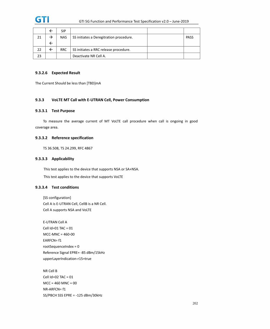
GTI 5G Function and Performance Test Specification v2.0 – June-2019
202
SIP
21
NAS SS initiates a Deregitration procedure. PASS
22 RRC SS initiates a RRC release procedure.
23 Deactivate NR Cell A.
9.3.2.6 Expected Result
The Current Should be less than [TBD]mA
9.3.3 VoLTE MT Call with E-UTRAN Cell, Power Consumption
9.3.3.1 Test Purpose
To measure the average current of MT VoLTE call procedure when call is ongoing in good
coverage area.
9.3.3.2 Reference specification
TS 36.508, TS 24.299, RFC 4867
9.3.3.3 Applicability
This test applies to the device that supports NSA or SA+NSA.
This test applies to the device that supports VoLTE
9.3.3.4 Test conditions
[SS configuration]
Cell A is E-UTRAN Cell, CellB is a NR Cell.
Cell A supports NSA and VoLTE
E-UTRAN Cell A
Cell Id=01 TAC = 01
MCC-MNC = 460-00
EARFCN= f1
rootSequenceIndex = 0
Reference Signal EPRE= -85 dBm/15kHz
upperLayerIndication-r15=true
NR Cell B
Cell Id=02 TAC = 01
MCC = 460 MNC = 00
NR-ARFCN= f1
SS/PBCH SSS EPRE = -125 dBm/30kHz

GTI 5G Function and Performance Test Specification v2.0 – June-2019
203
[UE configuration]
The test UICC with USIM should be inserted
The UE is in AUTOMATIC network selection mode.
UE works in NSA mode.
IMS VoLTE Feature should be enabled on DUT
[Initial conditions]
SS
E-UTRAN Cell A is not active
NR Cell B is not active
The test shall be performed under ideal radio conditions.
UE
UE is powered off
9.3.3.5 Test procedure
Table 5.1.1.5-1: Time of cell power level and parameter changes
Time E-UTRAN Cell A NR Cell C Remark
T0 -85 -90
PREAMBLE
18. Activate E-UTRAN Cell A, NR Cell B.The SS configures the corresponding Master Information
Block and System Information Block broadcast.
19. The SS configures the initial power according to T0 in Table 9.3.3.5-1.
20. The UE is powered ON.
21. The UE performs the registration procedure with activation of the initial default EPS bearer
on Cell A (see 36.508, 4.5.2 ).
22. The SS sends an ue-CapabilityRequest including the RAT type “eutra-nr”.
23. Verify the UE sends UECapabilityInformation message including the RAT type “eutra-nr”.
24. The SS sends an RRCConnectionReconfiguration message containing NR RRCReconfiguration
message to add Cell B as NR PS-Cell with Split DRB.
25. The UE sends an RRCConnectionReconfigurationComplete message containing NR
RRCReconfigurationComplete message.
26. UE inititaes the PDN connectivity procedure for the IMS PDN and Default EPS procedure for
IMS PDN is completed in Cell A.
27. IMS Registration is successful in Cell A
28. Verify that Data tranfer(Ping) perofrmed on NR cell B
MAIN BODY
29. start power consumption tester records the changes of current and voltage and start the MT
VoLTE call from tester
30. Verify the RTP packet flow between UE and SS in both directions and stop the VoLTE call

GTI 5G Function and Performance Test Specification v2.0 – June-2019
204
after 3 minutes
31. Stop the power consumption measurement and calculate the average current for VoLTE call
POSTAMBLE
32. The SS initiates a Detach procedure.
33. The SS initiates a RRC release procedure.
34. Deactivate E-UTRAN Cell A and NR Cell B.
Table 5.1.1.5-2: Message Sequence
Step Message Sequence Verdict
U-S Layer Message Specific Contents
Connect the power consumption tester to
the UE
1 RRC Activate E-UTRAN Cell A and NR Cell B.
2 SS configures the initial power according to
T0 in Table 9.3.3.5-1.
3 UE Switch On UE AT Command
4
NAS
RRC
UE performs the registration procedure with
activation of the initial default EPS bearer on
Cell A (see 36.508, 4.5.2 ).
PASS
5 RRC The SS sends an ue-CapabilityRequest
including the RAT type “eutra-nr”.
6 RRC Verify the UE sends UECapabilityInformation
message including the RAT type “eutra-nr”.
PASS
7 NAS
RRC
SS sends an RRCConnectionReconfiguration
message containing NR RRCReconfiguration
message to add Cell B as NR PS-Cell with Split
DRB.
8 RRC UE sends an
RRCConnectionReconfigurationComplete
message containing NR
RRCReconfigurationComplete message.
PASS
9
UE initiates the PDN Connectivity Procedure
for IMS PDN
10
IMS Registration Procedure is successful in
Cell A
PASS
11 Verify the data transmission is performed
successfully on NR Cell B.
PASS
12
Start the power consumption recorder for
current measurements and Start MT VoLTE
call from SS
13 Verify the RTP packet flow between UE and
SS and stop the VolTE call after 3 minutes
PASS

GTI 5G Function and Performance Test Specification v2.0 – June-2019
205
14 Stop the power consumption and calculte the
average current of the VoLTE call
15
NAS SS initiates a Detach procedure. PASS
16 RRC SS initiates a RRC release procedure.
17 Deactivate E-UTRAN Cell A and NR Cell B.
9.3.3.6 Expected Result
Record the test results of the current9.4 Data Transmission, Power Consumption
9.4 Data Transmission, Power Consumption
9.4.1 UL Data Transmission, Power Consumption,SA
9.4.1.1 Power Consumption with UL Data Transfer, SA (UL Single Tx – 64 QAM)
9.4.1.1.1 Test Purpose
Setup a Data bearer with NR cell with typical transmit level. Measure the power consumption
when UE transmits TCP data with uplink 64QAM
9.4.1.1.2 Reference specification
TS 38.508, TS 38.331, TS 38.300
9.4.1.1.3 Applicability
This test applies to Type 1 and Type 2 devices as described in clause 4.2.
9.4.1.1.4 Test conditions
[SS configuration]
Cell A is a NR Cell.
Cell A supports SA
NR Cell A
Cell Id=01 TAC = 01
MCC = 460 MNC = 00
NR-ARFCN= f1
SS/PBCH SSS EPRE = -125 dBm/30kHz
RB Allocation UL = Full
UL Modulation / Coding = 28
mcs-Table in PUSCH-Config = qam64
P_Max = 3 dBm
[UE configuration]

GTI 5G Function and Performance Test Specification v2.0 – June-2019
206
The test UICC with USIM should be inserted
The UE is in AUTOMATIC network selection mode.
UE works in SA mode.
[Initial conditions]
SS
NR Cell A is not active
UL MCS = 18
The test shall be performed under ideal radio conditions.
UE
UE is powered off
9.4.1.1.5 Test procedure
Table 5.1.1.5-1: Time of cell power level and parameter changes
Time NR Cell A Remark
T0 -90
PREAMBLE
1. Activate NR Cell A.The SS configures the corresponding Master Information Block and System
Information Block broadcast.
2. The SS configures the initial power according to T0 in Table 9.4.1.1.5-1.
3. The UE is powered ON.
4. The UE performs the registration procedure on Cell A (see 38.508, Table 4.5.2.2 till Step 18 ).
MAIN BODY
5. The power consumption tester records the changes of current.
6. Setup a TCP session and verify that UE uploads data correctly. Verify that UE TX power
meeting the requirement in test conditions. Keep the service for 5 minutes.
7. Get the value of power consumption tester during step 6 and calculate the average TCP
throughput
8. Repeat Step 6 and 7 for one more time
9. Calculate the overall average power consumption and TCP throughput
POSTAMBLE
10. The SS initiates a Deregistration procedure.
11. The SS initiates a RRC release procedure.
12. Deactivate NR Cell A.
Table 5.1.1.5-2: Message Sequence
Step Message Sequence Verdict
U-S Layer Message Specific Contents
Connect the power consumption tester to

GTI 5G Function and Performance Test Specification v2.0 – June-2019
207
the UE
1 RRC Activate NR Cell A.
2 SS configures the initial power according to
T0 in Table 9.4.1.1.5-1.
3 UE Switch On UE AT Command
4
NAS
RRC
UE performs the registration procedure (see
38.508, Table 4.5.2.2 till Step 18).
PASS
5 Power consumption tester records the
chnages of current and voltage
6 UE UE uploads the data correctly in NR Cell A.
Keep services for 5 minutes
PASS
7 Get the power concumption tester values
and note down the TCP throughput value
8 Repeat step 6 and 7 for one more time
9 Calculate the overall average power
consumption value and TCP Data throughput
value
10
NAS SS initiates a Deregistration procedure. PASS
11 RRC SS initiates a RRC release procedure.
12 Deactivate NR Cell A.
9.4.1.1.6 Expected Result
Record the average TCP throughput and current in the following Table. The Current Should be less
than [TBD]mA
Table 9.4.1.1.6-1: Average throughput and current
UL TCP Throughput(Mbps) Average Current(mA)
9.4.1.2 Power Consumption with UL Data Transfer, SA (UL 2 Tx – 64 QAM)
9.4.1.2.1 Test Purpose
Setup a Data bearer with NR cell with typical transmit level. Measure the power consumption
when UE transmits TCP data with uplink 64QAM and 2X2 MIMO
9.4.1.2.2 Reference specification
TS 38.508, TS 38.331, TS 38.300
9.4.1.2.3 Applicability
This test applies to Type 1 and Type 2 devices as described in clause 4.2.
9.4.1.2.4 Test conditions

GTI 5G Function and Performance Test Specification v2.0 – June-2019
208
[SS configuration]
Cell A is a NR Cell.
Cell A supports SA
NR Cell A
Cell Id=01 TAC = 01
MCC = 460 MNC = 00
NR-ARFCN= f1
SS/PBCH SSS EPRE = -125 dBm/30kHz
RB Allocation UL = Full
UL Modulation / Coding = 28
mcs-Table in PUSCH-Config = qam64
P_Max = 0 dBm
UL MIMO = 2X2
[UE configuration]
The test UICC with USIM should be inserted
The UE is in AUTOMATIC network selection mode.
UE works in SA mode.
[Initial conditions]
SS
NR Cell A is not active
The test shall be performed under ideal radio conditions.
UE
UE is powered off
9.4.1.2.5 Test procedure
Table 5.1.1.5-1: Time of cell power level and parameter changes
Time NR Cell A Remark
T0 -90
PREAMBLE
1. Activate NR Cell A.The SS configures the corresponding Master Information Block and System
Information Block broadcast.
2. The SS configures the initial power according to T0 in Table 9.4.1.2.5-1.
3. The UE is powered ON.
4. The UE performs the registration procedure on Cell A (see 38.508, Table 4.5.2.2 till Step 18 ).
MAIN BODY
5. The power consumption tester records the changes of current.
6. Setup a TCP session and verify that UE uploads data correctly. Verify that UE TX power
meeting the requirement in test conditions. Keep the service for 5 minutes

GTI 5G Function and Performance Test Specification v2.0 – June-2019
209
7. Get the value of power consumption tester during step 6 and calculate the average TCP
throughput
8. Repeat Step 6 and 7 for one more time
9. Calculate the overall average power consumption and TCP throughput
POSTAMBLE
10. The SS initiates a Deregistration procedure.
11. The SS initiates a RRC release procedure.
12. Deactivate NR Cell A.
Table 5.1.1.5-2: Message Sequence
Step Message Sequence Verdict
U-S Layer Message Specific Contents
Connect the power consumption tester to
the UE
1 RRC Activate NR Cell A.
2 SS configures the initial power according to
T0 in Table 9.4.1.2.5-1.
3 UE Switch On UE AT Command
4
NAS
RRC
UE performs the registration procedure (see
38.508, Table 4.5.2.2 till Step 18).
PASS
5 Power consumption tester records the
chnages of current and voltage
6 UE UE uploads the data correctly in NR Cell A.
Keep services for 5 minutes
PASS
7 Get the power concumption tester values
and note down the TCP throughput value
8 Repeat step 6 and 7 for one more times
9 Calculate the overall average power
consumption value and TCP Data throughput
value
10
NAS SS initiates a Deregistration procedure. PASS
11 RRC SS initiates a RRC release procedure.
12 Deactivate NR Cell A.
9.4.1.2.6 Expected Result
Record the average TCP throughput and current in the following Table. The Current Should be less
than [TBD]mA
Table 9.4.1.2.6-1: Average throughput and current
UL TCP Throughput(Mbps) Average Current(mA)

GTI 5G Function and Performance Test Specification v2.0 – June-2019
210
9.4.1.3 Power Consumption with UL Data Transfer, SA (UL Single Tx – 256 QAM)
9.4.1.3.1 Test Purpose
Setup a Data bearer with NR cell with maximum transmit level at UE. Measure the power
consumption when UE transmits TCP data with uplink 256QAM
9.4.1.3.2 Reference specification
TS 38.508, TS 38.331, TS 38.300
9.4.1.3.3 Applicability
This test applies to Type 1 and Type 2 devices as described in clause 4.2.
9.4.1.3.4 Test conditions
[SS configuration]
Cell A is a NR Cell.
Cell A supports SA
NR Cell A
Cell Id=01 TAC = 01
MCC = 460 MNC = 00
NR-ARFCN= f1
SS/PBCH SSS EPRE = -125 dBm/30kHz
RB Allocation UL = Full
UL Modulation / Coding = 27
mcs-Table in PUSCH-Config = qam256
P_Max = 26 dBm
[UE configuration]
The test UICC with USIM should be inserted
The UE is in AUTOMATIC network selection mode.
UE works in SA mode.
[Initial conditions]
SS
NR Cell A is not active
The test shall be performed under ideal radio conditions.
UE
UE is powered off
9.4.1.3.5 Test procedure

GTI 5G Function and Performance Test Specification v2.0 – June-2019
211
Table 5.1.1.5-1: Time of cell power level and parameter changes
Time NR Cell A Remark
T0 -90
PREAMBLE
1. Activate NR Cell A.The SS configures the corresponding Master Information Block and System
Information Block broadcast.
2. The SS configures the initial power according to T0 in Table 9.4.1.3.5-1.
3. The UE is powered ON.
4. The UE performs the registration procedure on Cell A (see 38.508, Table 4.5.2.2 till Step 18).
MAIN BODY
5. The power consumption tester records the changes of current.
6. Setup a TCP session and verify that UE uploads data correctly. Verify that UE TX power
meeting the requirement in test conditions. Keep the service for 5 minutes
7. Get the value of power consumption tester during step 6 and calculate the average TCP
throughput
8. Repeat Step 6 and 7 for one more time
9. Calculate the overall average power consumption and TCP throughput
POSTAMBLE
10. The SS initiates a Deregistration procedure.
11. The SS initiates a RRC release procedure.
12. Deactivate NR Cell A.
Table 9.4.1.3.55.1.1.5-2: Message Sequence
Step Message Sequence Verdict
U-S Layer Message Specific Contents
Connect the power consumption tester to
the UE
1 RRC Activate NR Cell A.
2 SS configures the initial power according to
T0 in Table 9.4.1.3.5-1.
3 UE Switch On UE AT Command
4
NAS
RRC
UE performs the registration procedure (see
38.508, Table 4.5.2.2 till Step 18).
PASS
5 Power consumption tester records the
chnages of current and voltage
6 UE UE uploads the data correctly in NR Cell A.
Keep services for 5 minutes
PASS
7 Get the power concumption tester values
and note down the TCP throughput value
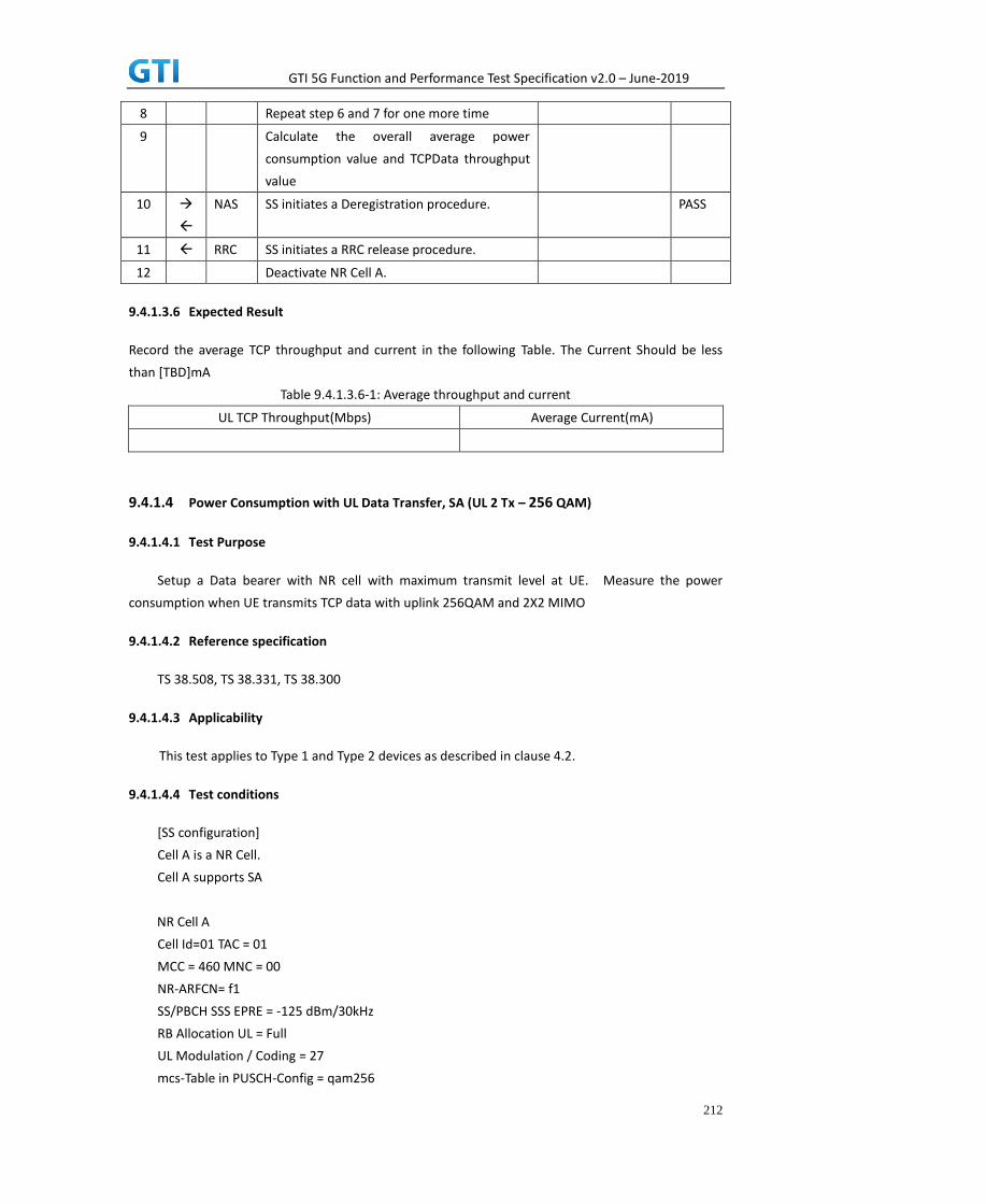
GTI 5G Function and Performance Test Specification v2.0 – June-2019
212
8 Repeat step 6 and 7 for one more time
9 Calculate the overall average power
consumption value and TCPData throughput
value
10
NAS SS initiates a Deregistration procedure. PASS
11 RRC SS initiates a RRC release procedure.
12 Deactivate NR Cell A.
9.4.1.3.6 Expected Result
Record the average TCP throughput and current in the following Table. The Current Should be less
than [TBD]mA
Table 9.4.1.3.6-1: Average throughput and current
UL TCP Throughput(Mbps) Average Current(mA)
9.4.1.4 Power Consumption with UL Data Transfer, SA (UL 2 Tx – 256 QAM)
9.4.1.4.1 Test Purpose
Setup a Data bearer with NR cell with maximum transmit level at UE. Measure the power
consumption when UE transmits TCP data with uplink 256QAM and 2X2 MIMO
9.4.1.4.2 Reference specification
TS 38.508, TS 38.331, TS 38.300
9.4.1.4.3 Applicability
This test applies to Type 1 and Type 2 devices as described in clause 4.2.
9.4.1.4.4 Test conditions
[SS configuration]
Cell A is a NR Cell.
Cell A supports SA
NR Cell A
Cell Id=01 TAC = 01
MCC = 460 MNC = 00
NR-ARFCN= f1
SS/PBCH SSS EPRE = -125 dBm/30kHz
RB Allocation UL = Full
UL Modulation / Coding = 27
mcs-Table in PUSCH-Config = qam256

GTI 5G Function and Performance Test Specification v2.0 – June-2019
213
P_Max = 23 dBm
UL MIMO = 2X2
[UE configuration]
The test UICC with USIM should be inserted
The UE is in AUTOMATIC network selection mode.
UE works in SA mode.
[Initial conditions]
SS
NR Cell A is not active
The test shall be performed under ideal radio conditions.
UE
UE is powered off
9.4.1.4.5 Test procedure
Table 5.1.1.5-1: Time of cell power level and parameter changes
Time NR Cell A Remark
T0 -90
PREAMBLE
1. Activate NR Cell A.The SS configures the corresponding Master Information Block and System
Information Block broadcast.
2. The SS configures the initial power according to T0 in Table 9.4.1.4.5-1.
3. The UE is powered ON.
4. The UE performs the registration procedure on Cell A (see 38.508, Table 4.5.2.2 till Step 18).
MAIN BODY
5. The power consumption tester records the changes of current.
6. Setup a TCP session and verify that UE uploads data correctly. Verify that UE TX power
meeting the requirement in test conditions. Keep the service for 5 minutes
7. Get the value of power consumption tester during step 6 and calculate the average TCP
throughput
8. Repeat Step 6 and 7 for one more time
9. Calculate the overall average power consumption and TCP throughput
POSTAMBLE
10. The SS initiates a Deregistration procedure.
11. The SS initiates a RRC release procedure.
12. Deactivate NR Cell A.
Table 5.1.1.5-2: Message Sequence
Step Message Sequence Verdict

GTI 5G Function and Performance Test Specification v2.0 – June-2019
214
U-S Layer Message Specific Contents
Connect the power consumption tester to
the UE
1 RRC Activate NR Cell A.
2 SS configures the initial power according to
T0 in Table 9.4.1.4.5-1.
3 UE Switch On UE AT Command
4
NAS
RRC
UE performs the registration procedure (see
38.508, Table 4.5.2.2 till Step 18).
PASS
5 Power consumption tester records the
chnages of current and voltage
6 UE UE uploads the data correctly in NR Cell A.
Keep services for 5 minutes
PASS
7 Get the power concumption tester values
and note down the TCP throughput value
8 Repeat step 6 and 7 for one more time
9 Calculate the overall average power
consumption value and TCP Data throughput
value
10
NAS SS initiates a Deregistration procedure. PASS
11 RRC SS initiates a RRC release procedure.
12 Deactivate NR Cell A.
9.4.1.4.6 Expected Result
Record the average TCP throughput and current in the following Table. The Current Should be
less than [TBD]mA
Table 9.4.1.4.6-1: Average throughput and current
UL TCP Throughput(Mbps) Average Current(mA)
9.4.2 DL Data Transmission, Power Consumption, SA
9.4.2.1 Power Consumption with DL Data Transfer, SA (64 QAM)
9.4.2.1.1 Test Purpose
Setup a Data bearer with NR cell with typical transmit level. Measure the power consumption
when UE receives TCP data with downlink 64QAM
9.4.2.1.2 Reference specification
TS 38.508, TS 38.331, TS 38.300

GTI 5G Function and Performance Test Specification v2.0 – June-2019
215
9.4.2.1.3 Applicability
This test applies to Type 1 and Type 2 devices as described in clause 4.2.
9.4.2.1.4 Test conditions
[SS configuration]
Cell A is a NR Cell.
Cell A supports SA
NR Cell A
Cell Id=01 TAC = 01
MCC = 460 MNC = 00
NR-ARFCN= f1
SS/PBCH SSS EPRE = -125 dBm/30kHz
RB Allocation DL = Full
DL Modulation / Coding= 28
mcs-Table in PDSCH-Config = qam64
P_Max = 0 dBm
DL MIMO = 4*4
[UE configuration]
The test UICC with USIM should be inserted
The UE is in AUTOMATIC network selection mode.
UE works in SA mode.
[Initial conditions]
SS
NR Cell A is not active
The test shall be performed under ideal radio conditions.
UE
UE is powered off
9.4.2.1.5 Test procedure
Table 5.1.1.5-1: Time of cell power level and parameter changes
Time NR Cell A Remark
T0 -90
PREAMBLE
1. Activate NR Cell A.The SS configures the corresponding Master Information Block and System
Information Block broadcast.
2. The SS configures the initial power according to T0 in Table 9.4.2.1.5-1.
3. The UE is powered ON.

GTI 5G Function and Performance Test Specification v2.0 – June-2019
216
4. The UE performs the registration procedure on Cell A (see 38.508, Table 4.5.2.2 till Step 18 ).
MAIN BODY
5. The power consumption tester records the changes of current.
6. Setup a TCP session and verify that UE downloads data correctly. Keep the service for 5
minutes
7. Get the value of power consumption tester during step 6 and calculate the average TCP
throughput
8. Repeat Step 6 and 7 for one more time
9. Calculate the overall average power consumption and TCP throughput
POSTAMBLE
10. The SS initiates a Deregistration procedure.
11. The SS initiates a RRC release procedure.
12. Deactivate NR Cell A.
Table 5.1.1.5-2: Message Sequence
Step Message Sequence Verdict
U-S Layer Message Specific Contents
Connect the power consumption tester to
the UE
1 RRC Activate NR Cell A.
2 SS configures the initial power according to
T0 in Table 9.4.2.1.5-1.
3 UE Switch On UE AT Command
4
NAS
RRC
UE performs the registration procedure (see
38.508, Table 4.5.2.2 till Step 18).
PASS
5 Power consumption tester records the
chnages of current
6 UE UE downloads the data correctly in NR Cell A.
Keep services for 5 minutes
PASS
7 Get the power concumption tester values
and note down the TCP throughput value
8 Repeat step 6 and 7 for one more time
9 Calculate the overall average power
consumption value and TCP Data throughput
value
10
NAS SS initiates a Deregistration procedure. PASS
11 RRC SS initiates a RRC release procedure.
12 Deactivate NR Cell A.
9.4.2.1.6 Expected Result

GTI 5G Function and Performance Test Specification v2.0 – June-2019
217
Record the average TCP throughput and current in the following Table. The Current Should be less
than [TBD]mA
Table 9.4.2.1.6-1: Average throughput and current
DL TCP Throughput(Mbps) Average Current(mA)
9.4.2.2 Power Consumption with DL Data Transfer, SA (256 QAM)
9.4.2.2.1 Test Purpose
Setup a Data bearer with NR cell with typical transmit level. Measure the power consumption
when UE receives TCP data with downlink 256QAM
9.4.2.2.2 Reference specification
TS 38.508, TS 38.331, TS 38.300
9.4.2.2.3 Applicability
This test applies to Type 1 and Type 2 devices as described in clause 4.2.
9.4.2.2.4 Test conditions
[SS configuration]
Cell A is a NR Cell.
Cell A supports SA
NR Cell A
Cell Id=01 TAC = 01
MCC = 460 MNC = 00
NR-ARFCN= f1
SS/PBCH SSS EPRE = -125 dBm/30kHz
RB Allocation DL = Full
DL Modulation / Coding= 27
mcs-Table in PDSCH-Config = qam256
P_Max = 0 dBm
DL MIMO = 4X4
[UE configuration]
The test UICC with USIM should be inserted
The UE is in AUTOMATIC network selection mode.
UE works in SA mode.
[Initial conditions]
SS
NR Cell A is not active
The test shall be performed under ideal radio conditions.

GTI 5G Function and Performance Test Specification v2.0 – June-2019
218
UE
UE is powered off
9.4.2.2.5 Test procedure
Table 5.1.1.5-1: Time of cell power level and parameter changes
Time NR Cell A Remark
T0 -90
PREAMBLE
1. Activate NR Cell A.The SS configures the corresponding Master Information Block and System
Information Block broadcast.
2. The SS configures the initial power according to T0 in Table 9.4.2.2.5-1.
3. The UE is powered ON.
4. The UE performs the registration procedure on Cell A (see 38.508, Table 4.5.2.2 till Step 18).
MAIN BODY
5. The power consumption tester records the changes of current.
6. Setup a TCPsession and verify that UE downloads data correctly. Keep the service for 5
minutes
7. Get the value of power consumption tester during step 6 and calculate the average TCP
throughput
8. Repeat Step 6 and 7 for one more time
9. Calculate the overall average power consumption and TCP throughput
POSTAMBLE
10. The SS initiates a Deregistration procedure.
11. The SS initiates a RRC release procedure.
12. Deactivate NR Cell A.
Table 5.1.1.5-2: Message Sequence
Step Message Sequence Verdict
U-S Layer Message Specific Contents
Connect the power consumption tester to
the UE
1 RRC Activate NR Cell A.
2 SS configures the initial power according to
T0 in Table 9.4.2.2.5-1.
3 UE Switch On UE AT Command
4
NAS
RRC
UE performs the registration procedure (see
38.508, Table 4.5.2.2 till Step 18).
PASS
5 Power consumption tester records the
chnages of current and voltage
6 UE UE downloads the data correctly in NR Cell A. PASS

GTI 5G Function and Performance Test Specification v2.0 – June-2019
219
Keep services for 5 minutes
7 Get the power concumption tester values
and note down the TCP throughput value
8 Repeat step 6 and 7 for one more time
9 Calculate the overall average power
consumption value and TCP Data throughput
value
10
NAS SS initiates a Deregistration procedure. PASS
11 RRC SS initiates a RRC release procedure.
12 Deactivate NR Cell A.
9.4.2.2.6 Expected Result
Record the average TCP throughput and current in the following Table. The Current Should be
less than [TBD]mA
Table 9.4.2.2.6-1: Average throughput and current
DL TCP Throughput(Mbps) Average Current(mA)
9.4.3 Bi-direction Data Transmission, Power Consumption, SA
9.4.3.1 Power Consumption with Bidirectional Data Transfer, SA (UL Single Tx – 64 QAM)
9.4.3.1.1 Test Purpose
Setup a Data bearer with NR cell with typical transmit level. Measure the power consumption
when UE transmits and receives TCP data simultaneously with 64QAM
9.4.3.1.2 Reference specification
TS 38.508, TS 38.331, TS 38.300
9.4.3.1.3 Applicability
This test applies to Type 1 and Type 2 devices as described in clause 4.2.
9.4.3.1.4 Test conditions
[SS configuration]
Cell A is a NR Cell.
Cell A supports SA
NR Cell A
Cell Id=01 TAC = 01
MCC = 460 MNC = 00

GTI 5G Function and Performance Test Specification v2.0 – June-2019
220
NR-ARFCN= f1
SS/PBCH SSS EPRE = -125 dBm/30kHz
RB Allocation UL = Full
RB Allocation DL = Full
UL Modulation / Coding = 28
mcs-Table in PUSCH-Config = qam64
DL Modulation / Coding = 28
mcs-Table in PDSCH-Config = qam64
P_Max = 3 dBm
DL MIMO = 4X4
[UE configuration]
The test UICC with USIM should be inserted
The UE is in AUTOMATIC network selection mode.
UE works in SA mode.
[Initial conditions]
SS
NR Cell A is not active
The test shall be performed under ideal radio conditions.
UE
UE is powered off
9.4.3.1.5 Test procedure
Table 5.1.1.5-1: Time of cell power level and parameter changes
Time NR Cell A Remark
T0 -90
PREAMBLE
1. Activate NR Cell A.The SS configures the corresponding Master Information Block and System
Information Block broadcast.
2. The SS configures the initial power according to T0 in Table 9.4.3.1.5-1.
3. The UE is powered ON.
4. The UE performs the registration procedure on Cell A (see 38.508, Table 4.5.2.2 till Step 18 ).
MAIN BODY
5. The power consumption tester records the changes of current.
6. Setup a TCP session and verify that UE downloads and uploads the data simultaneously.
Verify that UE TX power meeting the requirement in test conditions. Keep the service for 5
minutes
7. Get the value of power consumption tester during step 6 and calculate the average TCP
throughput
8. Repeat Step 6 and 7 for onemore time
9. Calculate the overall average power consumption and TCP throughput

GTI 5G Function and Performance Test Specification v2.0 – June-2019
221
POSTAMBLE
10. The SS initiates a Deregistration procedure.
11. The SS initiates a RRC release procedure.
12. Deactivate NR Cell A.
Table 5.1.1.5-2: Message Sequence
Step Message Sequence Verdict
U-S Layer Message Specific Contents
Connect the power consumption tester to
the UE
1 RRC Activate NR Cell A.
2 SS configures the initial power according to
T0 in Table 9.4.3.1.5-1.
3 UE Switch On UE AT Command
4
NAS
RRC
UE performs the registration procedure (see
38.508, Table 4.5.2.2 till Step 18).
PASS
5 Power consumption tester records the
chnages of current
6 UE UE donwloads/uploads the data correctly in
NR Cell A. Keep services for 5 minutes
PASS
7 Get the power concumption tester values
and note down the TCP throughput value
8 Repeat step 6 and 7 for one more time
9 Calculate the overall average power
consumption value and TCP Data throughput
value
10
NAS SS initiates a Deregistration procedure. PASS
11 RRC SS initiates a RRC release procedure.
12 Deactivate NR Cell A.
9.4.3.1.6 Expected Result
Record the average TCP throughput and current in the following Table. The Current Should be less
than [TBD]mA
Table 9.4.3.1.6-1: Average throughput and current
UL TCP Throughput (Mbps) DL TCP Throughput (Mbps) Average Current (mA)
9.4.3.2 Power Consumption with Bidirectional Data Transfer, SA (UL 2 Tx – 64 QAM)
9.4.3.2.1 Test Purpose
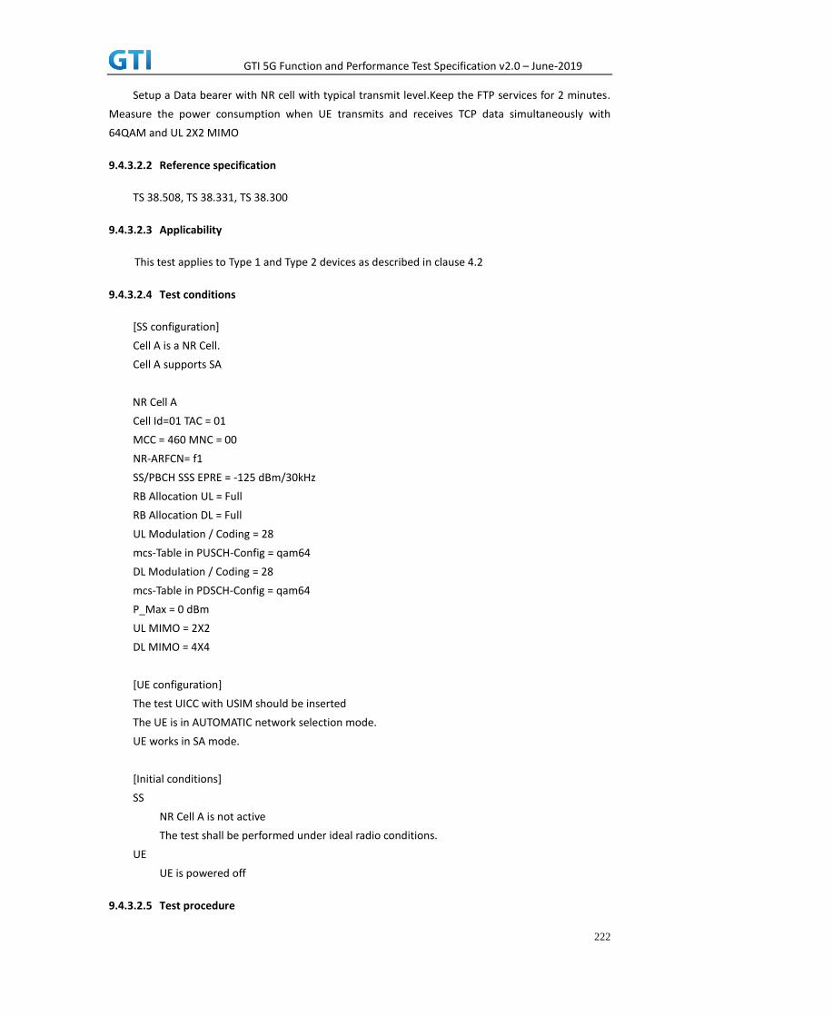
GTI 5G Function and Performance Test Specification v2.0 – June-2019
222
Setup a Data bearer with NR cell with typical transmit level.Keep the FTP services for 2 minutes.
Measure the power consumption when UE transmits and receives TCP data simultaneously with
64QAM and UL 2X2 MIMO
9.4.3.2.2 Reference specification
TS 38.508, TS 38.331, TS 38.300
9.4.3.2.3 Applicability
This test applies to Type 1 and Type 2 devices as described in clause 4.2
9.4.3.2.4 Test conditions
[SS configuration]
Cell A is a NR Cell.
Cell A supports SA
NR Cell A
Cell Id=01 TAC = 01
MCC = 460 MNC = 00
NR-ARFCN= f1
SS/PBCH SSS EPRE = -125 dBm/30kHz
RB Allocation UL = Full
RB Allocation DL = Full
UL Modulation / Coding = 28
mcs-Table in PUSCH-Config = qam64
DL Modulation / Coding = 28
mcs-Table in PDSCH-Config = qam64
P_Max = 0 dBm
UL MIMO = 2X2
DL MIMO = 4X4
[UE configuration]
The test UICC with USIM should be inserted
The UE is in AUTOMATIC network selection mode.
UE works in SA mode.
[Initial conditions]
SS
NR Cell A is not active
The test shall be performed under ideal radio conditions.
UE
UE is powered off
9.4.3.2.5 Test procedure
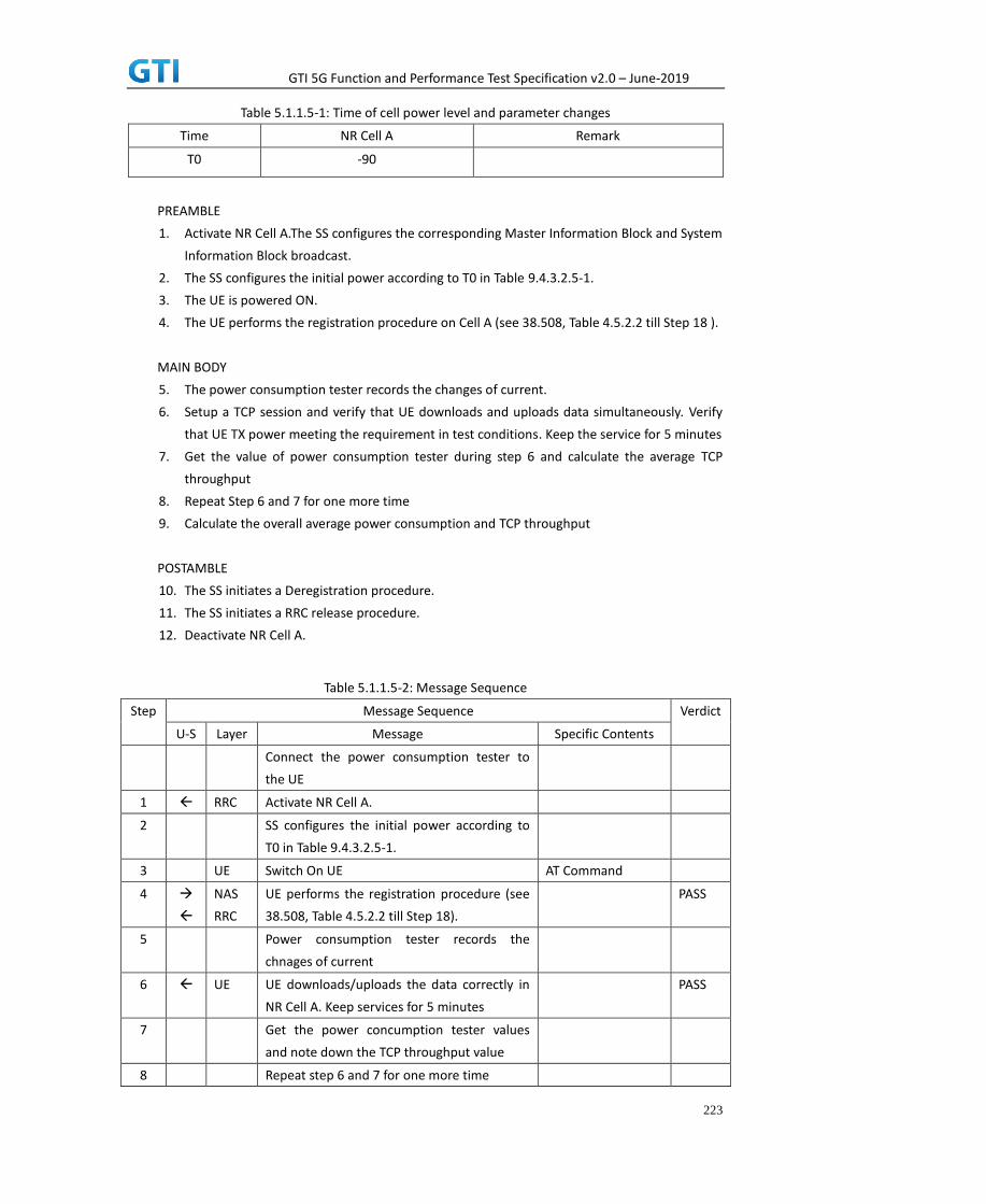
GTI 5G Function and Performance Test Specification v2.0 – June-2019
223
Table 5.1.1.5-1: Time of cell power level and parameter changes
Time NR Cell A Remark
T0 -90
PREAMBLE
1. Activate NR Cell A.The SS configures the corresponding Master Information Block and System
Information Block broadcast.
2. The SS configures the initial power according to T0 in Table 9.4.3.2.5-1.
3. The UE is powered ON.
4. The UE performs the registration procedure on Cell A (see 38.508, Table 4.5.2.2 till Step 18 ).
MAIN BODY
5. The power consumption tester records the changes of current.
6. Setup a TCP session and verify that UE downloads and uploads data simultaneously. Verify
that UE TX power meeting the requirement in test conditions. Keep the service for 5 minutes
7. Get the value of power consumption tester during step 6 and calculate the average TCP
throughput
8. Repeat Step 6 and 7 for one more time
9. Calculate the overall average power consumption and TCP throughput
POSTAMBLE
10. The SS initiates a Deregistration procedure.
11. The SS initiates a RRC release procedure.
12. Deactivate NR Cell A.
Table 5.1.1.5-2: Message Sequence
Step Message Sequence Verdict
U-S Layer Message Specific Contents
Connect the power consumption tester to
the UE
1 RRC Activate NR Cell A.
2 SS configures the initial power according to
T0 in Table 9.4.3.2.5-1.
3 UE Switch On UE AT Command
4
NAS
RRC
UE performs the registration procedure (see
38.508, Table 4.5.2.2 till Step 18).
PASS
5 Power consumption tester records the
chnages of current
6 UE UE downloads/uploads the data correctly in
NR Cell A. Keep services for 5 minutes
PASS
7 Get the power concumption tester values
and note down the TCP throughput value
8 Repeat step 6 and 7 for one more time

GTI 5G Function and Performance Test Specification v2.0 – June-2019
224
9 Calculate the overall average power
consumption value and TCP Data throughput
value
10
NAS SS initiates a Deregistration procedure. PASS
11 RRC SS initiates a RRC release procedure.
12 Deactivate NR Cell A.
9.4.3.2.6 Expected Result
Record the average TCP throughput and current in the following Table. The Current Should be less
than [TBD]mA
Table 9.4.3.2.6-1: Average throughput and current
UL TCP Throughput (Mbps) DL TCP Throughput (Mbps) Average Current (mA)
9.4.3.3 Power Consumption with Bidirectional Data Transfer, SA (UL Single Tx – 256
QAM)
9.4.3.3.1 Test Purpose
Setup a Data bearer with NR cell with maximum transmit level at UE. Measure the power
consumption when UE transmits and receives TCP data simultaneously with 256QAM
9.4.3.3.2 Reference specification
TS 38.508, TS 38.331, TS 38.300
9.4.3.3.3 Applicability
This test applies to Type 1 and Type 2 devices as described in clause 4.2.
9.4.3.3.4 Test conditions
[SS configuration]
Cell A is a NR Cell.
Cell A supports SA
NR Cell A
Cell Id=01 TAC = 01
MCC = 460 MNC = 00
NR-ARFCN= f1
SS/PBCH SSS EPRE = -125 dBm/30kHz
RB Allocation UL = Full
RB Allocation DL = Full
UL Modulation / Coding = 27

GTI 5G Function and Performance Test Specification v2.0 – June-2019
225
mcs-Table in PUSCH-Config = qam256
DL Modulation / Coding = 27
mcs-Table in PDSCH-Config = qam256
P_Max = 26 dBm
DL MIMO = 4X4
[UE configuration]
The test UICC with USIM should be inserted
The UE is in AUTOMATIC network selection mode.
UE works in SA mode.
[Initial conditions]
SS
NR Cell A is not active
The test shall be performed under ideal radio conditions.
UE
UE is powered off
9.4.3.3.5 Test procedure
Table 5.1.1.5-1: Time of cell power level and parameter changes
Time NR Cell A Remark
T0 -90
PREAMBLE
1. Activate NR Cell A.The SS configures the corresponding Master Information Block and System
Information Block broadcast.
2. The SS configures the initial power according to T0 in Table 9.4.3.3.5-1.
3. The UE is powered ON.
4. The UE performs the registration procedure on Cell A (see 38.508, Table 4.5.2.2 till Step 18).
MAIN BODY
5. The power consumption tester records the changes of current.
6. Setup a TCP session and verify that UE downloads and uploads the data simultaneously.
Verify that UE TX power meeting the requirement in test conditions. Keep the service for 5
minutes
7. Get the value of power consumption tester during step 6 and calculate the average TCP
throughput
8. Repeat Step 6 and 7 for one more time
9. Calculate the overall average power consumption and TCP throughput
POSTAMBLE
10. The SS initiates a Deregistration procedure.
11. The SS initiates a RRC release procedure.
12. Deactivate NR Cell A.
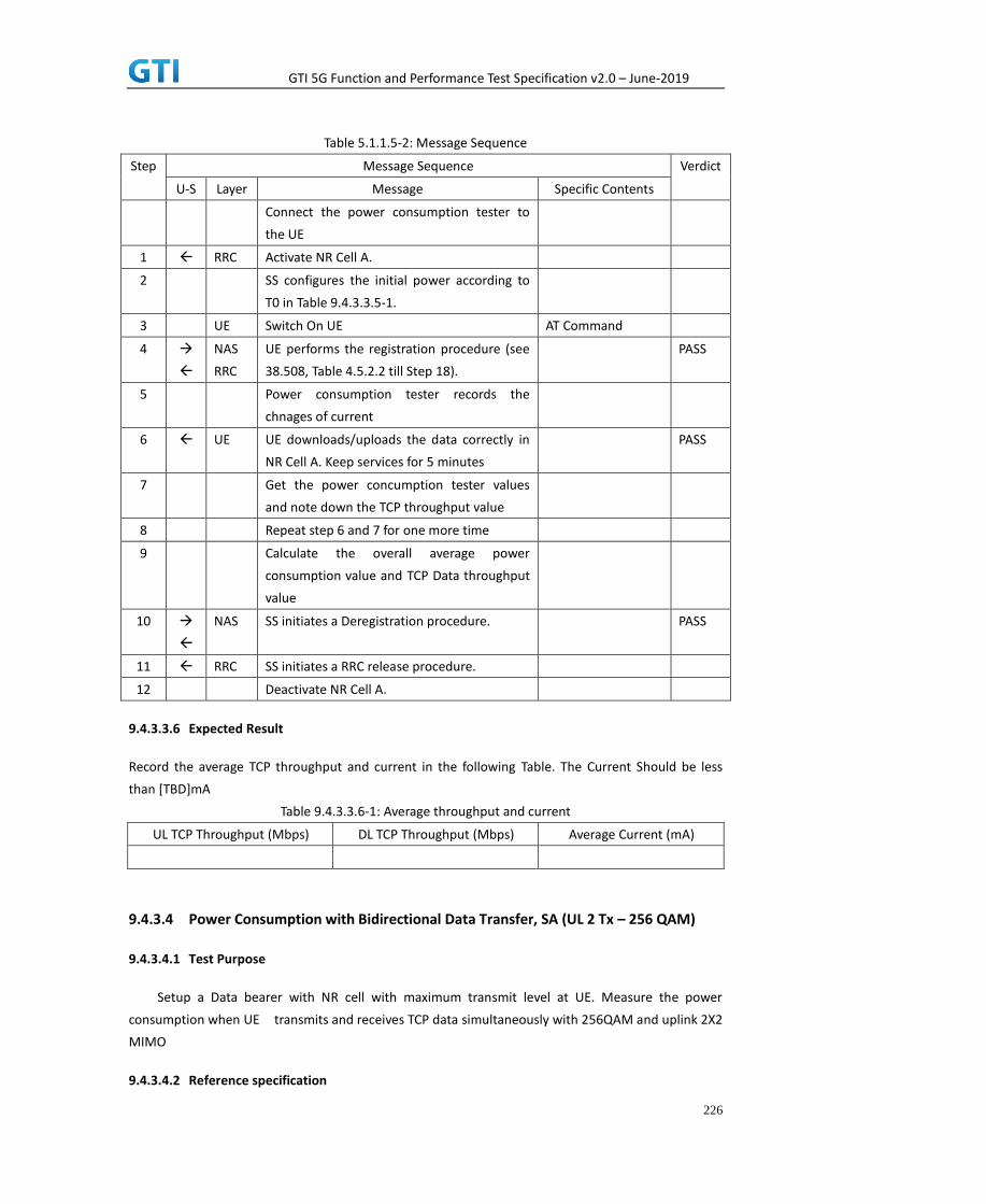
GTI 5G Function and Performance Test Specification v2.0 – June-2019
226
Table 5.1.1.5-2: Message Sequence
Step Message Sequence Verdict
U-S Layer Message Specific Contents
Connect the power consumption tester to
the UE
1 RRC Activate NR Cell A.
2 SS configures the initial power according to
T0 in Table 9.4.3.3.5-1.
3 UE Switch On UE AT Command
4
NAS
RRC
UE performs the registration procedure (see
38.508, Table 4.5.2.2 till Step 18).
PASS
5 Power consumption tester records the
chnages of current
6 UE UE downloads/uploads the data correctly in
NR Cell A. Keep services for 5 minutes
PASS
7 Get the power concumption tester values
and note down the TCP throughput value
8 Repeat step 6 and 7 for one more time
9 Calculate the overall average power
consumption value and TCP Data throughput
value
10
NAS SS initiates a Deregistration procedure. PASS
11 RRC SS initiates a RRC release procedure.
12 Deactivate NR Cell A.
9.4.3.3.6 Expected Result
Record the average TCP throughput and current in the following Table. The Current Should be less
than [TBD]mA
Table 9.4.3.3.6-1: Average throughput and current
UL TCP Throughput (Mbps) DL TCP Throughput (Mbps) Average Current (mA)
9.4.3.4 Power Consumption with Bidirectional Data Transfer, SA (UL 2 Tx – 256 QAM)
9.4.3.4.1 Test Purpose
Setup a Data bearer with NR cell with maximum transmit level at UE. Measure the power
consumption when UE transmits and receives TCP data simultaneously with 256QAM and uplink 2X2
MIMO
9.4.3.4.2 Reference specification

GTI 5G Function and Performance Test Specification v2.0 – June-2019
227
TS 38.508, TS 38.331, TS 38.300
9.4.3.4.3 Applicability
This test applies to Type 1 and Type 2 devices as described in clause 4.2.
9.4.3.4.4 Test conditions
[SS configuration]
Cell A is a NR Cell.
Cell A supports SA
NR Cell A
Cell Id=01 TAC = 01
MCC = 460 MNC = 00
NR-ARFCN= f1
SS/PBCH SSS EPRE = -125 dBm/30kHz
RB Allocation UL = Full
RB Allocation DL = Full
UL Modulation / Coding = 27
mcs-Table in PUSCH-Config = qam256
DL Modulation / Coding = 27
mcs-Table in PDSCH-Config = qam256
P_Max = 23 dBm
DL MIMO = 4X4
UL MIMO = 2X2
[UE configuration]
The test UICC with USIM should be inserted
The UE is in AUTOMATIC network selection mode.
UE works in SA mode.
[Initial conditions]
SS
NR Cell A is not active
The test shall be performed under ideal radio conditions.
UE
UE is powered off
9.4.3.4.5 Test procedure
Table 5.1.1.5-1: Time of cell power level and parameter changes
Time NR Cell A Remark
T0 -90

GTI 5G Function and Performance Test Specification v2.0 – June-2019
228
PREAMBLE
1. Activate NR Cell A.The SS configures the corresponding Master Information Block and System
Information Block broadcast.
2. The SS configures the initial power according to T0 in Table 9.4.3.4.5-1.
3. The UE is powered ON.
4. The UE performs the registration procedure on Cell A (see 38.508, Table 4.5.2.2 till Step 18).
MAIN BODY
5. The power consumption tester records the changes of current and voltage.
6. Setup a TCP session and verify that UE uploads data correctly. Verify that UE TX power
meeting the requirement in test conditions. Keep the service for 5 minutes
7. Get the value of power consumption tester during step 6 and calculate the average TCP
throughput
8. Repeat Step 6 and 7 for one more time
9. Calculate the overall average power consumption and TCP throughput
POSTAMBLE
10. The SS initiates a Deregistration procedure.
11. The SS initiates a RRC release procedure.
12. Deactivate NR Cell A.
Table 5.1.1.5-2: Message Sequence
Step Message Sequence Verdict
U-S Layer Message Specific Contents
Connect the power consumption tester to
the UE
1 RRC Activate NR Cell A.
2 SS configures the initial power according to
T0 in Table 9.4.3.4.5-1.
3 UE Switch On UE AT Command
4
NAS
RRC
UE performs the registration procedure (see
38.508, Table 4.5.2.2 till Step 18).
PASS
5 Power consumption tester records the
chnages of current
6 UE UE uploads the data correctly in NR Cell A.
Keep services for 5 minutes
PASS
7 Get the power concumption tester values
and note down the TCP throughput value
8 Repeat step 6 and 7 for one more time
9 Calculate the overall average power
consumption value and TCP Data throughput
value
10 NAS SS initiates a Deregistration procedure. PASS

GTI 5G Function and Performance Test Specification v2.0 – June-2019
229
11 RRC SS initiates a RRC release procedure.
12 Deactivate NR Cell A.
9.4.3.4.6 Expected Result
Record the average TCP throughput and current in the following Table. The Current Should be
less than [TBD]mA
Table 9.4.3.4.6-1: Average throughput and current
UL TCP Throughput (Mbps) DL TCP Throughput (Mbps) Average Current (mA)
9.4.4 UL Data Transmission, Power Consumption,NSA
9.4.4.1 Power Consumption with UL Data Transfer, NSA (SCG – 64 QAM)
9.4.4.1.1 Test Purpose
Setup a SCG bearer with NR as UL data path with typical transmit level. Measure the power
consumption when UE transmits TCP data with a TX power of 0 dBm
9.4.4.1.2 Reference specification
TS 36.508, TS 38.331, TS 38.300
9.4.4.1.3 Applicability
This test applies to Type 1 and Type 3 devices as described in clause 4.2.
9.4.4.1.4 Test conditions
[SS configuration]
Cell A is E-UTRAN Cell, CellB is a NR Cell.
Cell A supports NSA
E-UTRAN Cell A
Cell Id=01 TAC = 01
MCC-MNC = 460-00
EARFCN= f1
rootSequenceIndex = 0
Reference Signal EPRE= -85 dBm/15kHz
upperLayerIndication-r15=true
NR Cell B
Cell Id=02 TAC = 01
MCC = 460 MNC = 00

GTI 5G Function and Performance Test Specification v2.0 – June-2019
230
NR-ARFCN= f1
SS/PBCH SSS EPRE = -125 dBm/30kHz
RB Allocation UL = Full
UL_Modulation / Coding = 28
mcs-Table in PUSCH-Config = qam64
P_Max = 0 dBm
[UE configuration]
The test UICC with USIM should be inserted
The UE is in AUTOMATIC network selection mode.
UE works in NSA mode.
[Initial conditions]
SS
E-UTRAN Cell A is not active
NR Cell B is not active
The test shall be performed under ideal radio conditions.
UE
UE is powered off
9.4.4.1.5 Test procedure
Table 5.1.1.5-1: Time of cell power level and parameter changes
Time E-UTRAN Cell A NR Cell B Remark
T0 -85 -90
PREAMBLE
1. Activate E-UTRAN Cell A, NR Cell B.The SS configures the corresponding Master Information
Block and System Information Block broadcast.
2. The SS configures the initial power according to T0 in Table 9.4.4.1.5-1.
3. The UE is powered ON.
4. The UE performs the registration procedure with activation of the initial default EPS bearer
on Cell A (see 36.508, 4.5.2 ).
5. The SS sends an ue-CapabilityRequest including the RAT type “eutra-nr”.
6. Verify the UE sends UECapabilityInformation message including the RAT type “eutra-nr”.
7. The SS sends an RRCConnectionReconfiguration message containing NR RRCReconfiguration
message to add Cell B as NR PS-Cell with SCG DRB.
8. The UE sends an RRCConnectionReconfigurationComplete message containing NR
RRCReconfigurationComplete message.
MAIN BODY
9. The power consumption tester records the changes of current.
10. Setup a TCP session and verify that UE uploads data correctly. Verify that data transfer
happening in NR data path. Verify that UE TX power meeting the requirement in test
conditions. Keep the service for 5 minutes.

GTI 5G Function and Performance Test Specification v2.0 – June-2019
231
11. Get the value of power consumption tester during step 10 and calculate the average
throughput at transport layer
12. Repeat Step 9 to 11 for two more time
13. Calculate the overall average power consumption and throughput at the transport layer
POSTAMBLE
14. The SS initiates a Detach procedure.
15. The SS initiates a RRC release procedure.
16. Deactivate E-UTRAN Cell A and NR Cell B.
Table 5.1.1.5-2: Message Sequence
Step Message Sequence Verdict
U-S Layer Message Specific Contents
Connect the power consumption tester to
the UE
1 RRC Activate E-UTRAN Cell A and NR Cell B.
2 SS configures the initial power according to
T0 in Table 9.4.4.1.5-1.
3 UE Switch On UE AT Command
4
NAS
RRC
UE performs the registration procedure with
activation of the initial default EPS bearer on
Cell A (see 36.508, 4.5.2 ).
PASS
5 RRC The SS sends an ue-CapabilityRequest
including the RAT type “eutra-nr”.
6 RRC Verify the UE sends UECapabilityInformation
message including the RAT type “eutra-nr”.
PASS
7 NAS
RRC
SS sends an RRCConnectionReconfiguration
message containing NR RRCReconfiguration
message to add Cell B as NR PS-Cell with SCG
DRB.
8 RRC UE sends an
RRCConnectionReconfigurationComplete
message containing NR
RRCReconfigurationComplete message.
PASS
9 Power consumption tester records the
chnages of current
10 UE UE uploads the TCP data correctly in NR data
path. Keep services for 5 minutes
PASS
11 Get the power concumption tester values
and note down the throughput put value at
application layer level
12 Repeat step 9 to 11 for two times
13 Calculate the overall average power

GTI 5G Function and Performance Test Specification v2.0 – June-2019
232
consumption value and TCP Data throughput
14
NAS SS initiates a Detach procedure. PASS
15 RRC SS initiates a RRC release procedure.
16 Deactivate E-UTRAN Cell A and NR Cell B.
9.4.4.1.6 Expected Result
Record the average TCP throughput and current in the Table 错误!未找到引用源。-1. The Current
Should be less than [TBD]mA
Table 错误!未找到引用源。-1: Average throughput and current
UL TCP Throughput (Mbps) Average Current (mA)
[TBD] [TBD]
9.4.4.2 Power Consumption with UL Data Transfer, NSA (MCG & SCG – 64 QAM)
9.4.4.2.1 Test Purpose
Setup a MCG & SCG data bearer with with typical transmit level in a NSA cell. Measure the power
consumption when UE transmits TCP data with total TX power of 0 dBm for both LTE and NR cell
9.4.4.2.2 Reference specification
TS 36.508, TS 38.331, TS 38.300
9.4.4.2.3 Applicability
This test applies to Type 1 and Type 3 devices as described in clause 4.2.
9.4.4.2.4 Test conditions
[SS configuration]
Cell A is E-UTRAN Cell, CellB is a NR Cell.
Cell A supports NSA
E-UTRAN Cell A
Cell Id=01 TAC = 01
MCC-MNC = 460-00
EARFCN= f1
rootSequenceIndex = 0
Reference Signal EPRE= -85 dBm/15kHz
RB Allocation UL = Full
UL Modulation / Coding = 27
UL 64QAM=TRUE
P_Max = 0 dBm
upperLayerIndication-r15=true

GTI 5G Function and Performance Test Specification v2.0 – June-2019
233
NR Cell B
Cell Id=02 TAC = 01
MCC = 460 MNC = 00
NR-ARFCN= f1
SS/PBCH SSS EPRE = -125 dBm/30kHz
RB Allocation UL = Full
UL Modulation / Coding = 28
mcs-Table in PUSCH-Config = qam64
P_Max = 0 dBm
[UE configuration]
The test UICC with USIM should be inserted
The UE is in AUTOMATIC network selection mode.
UE works in NSA mode.
[Initial conditions]
SS
E-UTRAN Cell A is not active
NR Cell B is not active
The test shall be performed under ideal radio conditions.
UE
UE is powered off
9.4.4.2.5 Test procedure
Table 5.1.1.5-1: Time of cell power level and parameter changes
Time E-UTRAN Cell A NR Cell C Remark
T0 -85 -90
PREAMBLE
1. Activate E-UTRAN Cell A, NR Cell B.The SS configures the corresponding Master Information
Block and System Information Block broadcast.
2. The SS configures the initial power according to T0 in Table 9.4.4.2.5-1.
3. The UE is powered ON.
4. The UE performs the registration procedure with activation of the initial default EPS bearer
on Cell A (see 36.508, 4.5.2 ).
5. The SS sends an ue-CapabilityRequest including the RAT type “eutra-nr”.
6. Verify the UE sends UECapabilityInformation message including the RAT type “eutra-nr”.
7. The SS sends an RRCConnectionReconfiguration message containing NR RRCReconfiguration
message to add Cell B as NR PS-Cell with SCG DRB in addition with MCG bearer.
8. The UE sends an RRCConnectionReconfigurationComplete message containing NR
RRCReconfigurationComplete message.

GTI 5G Function and Performance Test Specification v2.0 – June-2019
234
MAIN BODY
9. The power consumption tester records the changes of current.
10. Setup a FTP session and verify that UE uploads data correctly. Verify that data transfer
happening in both MCG and SCG bearers. Verify that UE TX power meeting the requirement
in test conditions. Keep the service for 5 minutes
11. Get the value of power consumption tester during step 10 and calculate the average
throughput at transport layer
12. Repeat Step 9 to 11 for two more time
13. Calculate the overall average power consumption and throughput at the transport layer
POSTAMBLE
14. The SS initiates a Detach procedure.
15. The SS initiates a RRC release procedure.
16. Deactivate E-UTRAN Cell A and NR Cell B.
Table 5.1.1.5-2: Message Sequence
Step Message Sequence Verdict
U-S Layer Message Specific Contents
Connect the power consumption tester to
the UE
1 RRC Activate E-UTRAN Cell A and NR Cell B.
2 SS configures the initial power according to
T0 in Table 9.4.4.2.5-1.
3 UE Switch On UE AT Command
4
NAS
RRC
UE performs the registration procedure with
activation of the initial default EPS bearer on
Cell A (see 36.508, 4.5.2 ).
PASS
5 RRC The SS sends an ue-CapabilityRequest
including the RAT type “eutra-nr”.
6 RRC Verify the UE sends UECapabilityInformation
message including the RAT type “eutra-nr”.
PASS
7 NAS
RRC
SS sends an RRCConnectionReconfiguration
message containing NR RRCReconfiguration
message to add Cell B as NR PS-Cell with SCG
DRB in addition with existing MCG DRB
8 RRC UE sends an
RRCConnectionReconfigurationComplete
message containing NR
RRCReconfigurationComplete message.
PASS
9 Power consumption tester records the
changes of current
10 UE UE uploads the data correctly in both MCG
and SCG data path. Keep services for 5
PASS

GTI 5G Function and Performance Test Specification v2.0 – June-2019
235
minutes
11 Get the power concumption tester values
and note down the throughput put value at
transport layer level
12 Repeat step 9 to 11 for two times
13 Calculate the overall average power
consumption value and TCP Data throughput
value
14
NAS SS initiates a Detach procedure. PASS
15 RRC SS initiates a RRC release procedure.
16 Deactivate E-UTRAN Cell A and NR Cell B.
9.4.4.2.6 Expected Result
Record the average TCP throughput and current in the Table 错误!未找到引用源。-1.The Current
Should be less than [TBD]mA
Table 错误!未找到引用源。-1: Average throughput and current
Throughput (Mbps) Average
Current(mA) UL TCP Throughput UL MAC Throughput in MCG UL MAC Throughput in SCG
[TBD] [TBD] [TBD] [TBD]
9.4.4.3 Power Consumption with UL Data Transfer, NSA (SCG – 256 QAM)
9.4.4.3.1 Test Purpose
Setup a SCG bearer with NR as UL data path with maximum transmit level. Measure the power
consumption when UE transmits TCP data with a power of 23 dBm
9.4.4.3.2 Reference specification
TS 36.508, TS 38.331, TS 38.300
9.4.4.3.3 Applicability
This test applies to Type 1 and Type 3 devices as described in clause 4.2.
9.4.4.3.4 Test conditions
[SS configuration]
Cell A is E-UTRAN Cell, CellB is a NR Cell.
Cell A supports NSA
E-UTRAN Cell A
Cell Id=01 TAC = 01

GTI 5G Function and Performance Test Specification v2.0 – June-2019
236
MCC-MNC = 460-00
EARFCN= f1
rootSequenceIndex = 0
Reference Signal EPRE= -85 dBm/15kHz
upperLayerIndication-r15=true
NR Cell B
Cell Id=02 TAC = 01
MCC = 460 MNC = 00
NR-ARFCN= f1
SS/PBCH SSS EPRE = -125 dBm/30kHz
RB Allocation UL = Full
UL Modulation / Coding= 27
mcs-Table in PUSCH-Config = qam256
P_Max = 23 dBm
[UE configuration]
The test UICC with USIM should be inserted
The UE is in AUTOMATIC network selection mode.
UE works in NSA mode.
[Initial conditions]
SS
E-UTRAN Cell A is not active
NR Cell B is not active
The test shall be performed under ideal radio conditions.
UE
UE is powered off
9.4.4.3.5 Test procedure
Table 5.1.1.5-1: Time of cell power level and parameter changes
Time E-UTRAN Cell A NR Cell C Remark
T0 -85 -90
PREAMBLE
1. Activate E-UTRAN Cell A, NR Cell B.The SS configures the corresponding Master Information
Block and System Information Block broadcast.
2. The SS configures the initial power according to T0 in Table 9.4.4.3.5-1.
3. The UE is powered ON.
4. The UE performs the registration procedure with activation of the initial default EPS bearer
on Cell A (see 36.508, 4.5.2 ).
5. The SS sends an ue-CapabilityRequest including the RAT type “eutra-nr”.

GTI 5G Function and Performance Test Specification v2.0 – June-2019
237
6. Verify the UE sends UECapabilityInformation message including the RAT type “eutra-nr”.
7. The SS sends an RRCConnectionReconfiguration message containing NR RRCReconfiguration
message to add Cell B as NR PS-Cell with SCG DRB.
8. The UE sends an RRCConnectionReconfigurationComplete message containing NR
RRCReconfigurationComplete message.
MAIN BODY
9. The power consumption tester records the changes of current.
10. Setup a TCP session and verify that UE uploads data correctly. Verify that data transfer
happening in NR data path. Verify that UE TX power meeting the requirement in test
conditions. Keep the service for 5 minutes
11. Get the value of power consumption tester during step 10 and calculate the average
throughput at application layer
12. Repeat Step 9 to 11 for two more time
13. Calculate the overall average power consumption and throughput at the transpport layer
POSTAMBLE
14. The SS initiates a Detach procedure.
15. The SS initiates a RRC release procedure.
16. Deactivate E-UTRAN Cell A and NR Cell B.
Table 5.1.1.5-2: Message Sequence
Step Message Sequence Verdict
U-S Layer Message Specific Contents
Connect the power consumption tester to
the UE
1 RRC Activate E-UTRAN Cell A and NR Cell B.
2 SS configures the initial power according to
T0 in Table 9.4.4.3.5-1.
3 UE Switch On UE AT Command
4
NAS
RRC
UE performs the registration procedure with
activation of the initial default EPS bearer on
Cell A (see 36.508, 4.5.2 ).
PASS
5 RRC The SS sends an ue-CapabilityRequest
including the RAT type “eutra-nr”.
6 RRC Verify the UE sends UECapabilityInformation
message including the RAT type “eutra-nr”.
PASS
7 NAS
RRC
SS sends an RRCConnectionReconfiguration
message containing NR RRCReconfiguration
message to add Cell B as NR PS-Cell with SCG
DRB.
8 RRC UE sends an PASS

GTI 5G Function and Performance Test Specification v2.0 – June-2019
238
RRCConnectionReconfigurationComplete
message containing NR
RRCReconfigurationComplete message.
9 Power consumption tester records the
chnages of current
10 UE UE uploads the data correctly in NR data
path. Keep services for 5 minutes
PASS
11 Get the power concumption tester values
and note down the throughput put value at
transport layer level
12 Repeat step 9 to 11 for four times
13 Calculate the overall average power
consumption value and Application Data
throughput value
14
NAS SS initiates a Detach procedure. PASS
15 RRC SS initiates a RRC release procedure.
16 Deactivate E-UTRAN Cell A and NR Cell B.
9.4.4.3.6 Expected Result
Record the average TCP throughput and current in the Table 错误!未找到引用源。-1. The Current
Should be less than [TBD]mA
Table 错误!未找到引用源。-1: Average throughput and current
UL TCP Throughput (Mbps) Average Current (mA)
[TBD] [TBD]
9.4.4.4 Power Consumption with UL Data Transfer, NSA (MCG & SCG – 256 QAM)
9.4.4.4.1 Test Purpose
Setup a MCG & SCG data bearer with with typical transmit level in a NSA cell. Measure the power
consumption when UE transmits TCP data with a power of 23 dBm for both LTE and NR cell
9.4.4.4.2 Reference specification
TS 36.508, TS 38.331, TS 38.300
9.4.4.4.3 Applicability
This test applies to the device that supports NSA or SA+NSA.
9.4.4.4.4 Test conditions
[SS configuration]
Cell A is E-UTRAN Cell, CellB is a NR Cell.

GTI 5G Function and Performance Test Specification v2.0 – June-2019
239
Cell A supports NSA
E-UTRAN Cell A
Cell Id=01 TAC = 01
MCC-MNC = 460-00
EARFCN= f1
rootSequenceIndex = 0
Reference Signal EPRE= -85 dBm/15kHz
RB Allocation UL = Full
UL Modulation / Coding = 27
P_Max = 23 dBm
UL 64QAM = TRUE
upperLayerIndication-r15=true
NR Cell B
Cell Id=02 TAC = 01
MCC = 460 MNC = 00
NR-ARFCN= f1
SS/PBCH SSS EPRE = -125 dBm/30kHz
RB Allocation UL = Full
UL Modulation / Coding = 27
mcs-Table in PUSCH-Config = qam256
P_Max = 23 dBm
[UE configuration]
The test UICC with USIM should be inserted
The UE is in AUTOMATIC network selection mode.
UE works in NSA mode.
[Initial conditions]
SS
E-UTRAN Cell A is not active
NR Cell B is not active
The test shall be performed under ideal radio conditions.
UE
UE is powered off
9.4.4.4.5 Test procedure
Table 5.1.1.5-1: Time of cell power level and parameter changes
Time E-UTRAN Cell A NR Cell C Remark
T0 -85 -90
PREAMBLE

GTI 5G Function and Performance Test Specification v2.0 – June-2019
240
1. Activate E-UTRAN Cell A, NR Cell B.The SS configures the corresponding Master Information
Block and System Information Block broadcast.
2. The SS configures the initial power according to T0 in Table 9.4.4.4.5-1.
3. The UE is powered ON.
4. The UE performs the registration procedure with activation of the initial default EPS bearer
on Cell A (see 36.508, 4.5.2 ).
5. The SS sends an ue-CapabilityRequest including the RAT type “eutra-nr”.
6. Verify the UE sends UECapabilityInformation message including the RAT type “eutra-nr”.
7. The SS sends an RRCConnectionReconfiguration message containing NR RRCReconfiguration
message to add Cell B as NR PS-Cell with SCG DRB in addition with MCG bearer.
8. The UE sends an RRCConnectionReconfigurationComplete message containing NR
RRCReconfigurationComplete message.
MAIN BODY
9. The power consumption tester records the changes of current.
10. Setup a TCP session and verify that UE uploads data correctly. Verify that data transfer
happening in both MCG and SCG bearers. Verify that UE TX power meeting the requirement
in test conditions. Keep the service for 5 minutes
11. Get the value of power consumption tester during step 10 and calculate the average
throughput at transpport layer
12. Repeat Step 9 to 11 for two more time
13. Calculate the overall average power consumption and throughput at the transport level
POSTAMBLE
14. The SS initiates a Detach procedure.
15. The SS initiates a RRC release procedure.
16. Deactivate E-UTRAN Cell A and NR Cell B.
Table 5.1.1.5-2: Message Sequence
Step Message Sequence Verdict
U-S Layer Message Specific Contents
Connect the power consumption tester to
the UE
1 RRC Activate E-UTRAN Cell A and NR Cell B.
2 SS configures the initial power according to
T0 in Table 9.4.4.4.5-1.
3 UE Switch On UE AT Command
4
NAS
RRC
UE performs the registration procedure with
activation of the initial default EPS bearer on
Cell A (see 36.508, 4.5.2 ).
PASS
5 RRC The SS sends an ue-CapabilityRequest
including the RAT type “eutra-nr”.
6 RRC Verify the UE sends UECapabilityInformation
message including the RAT type “eutra-nr”.
PASS

GTI 5G Function and Performance Test Specification v2.0 – June-2019
241
7 NAS
RRC
SS sends an RRCConnectionReconfiguration
message containing NR RRCReconfiguration
message to add Cell B as NR PS-Cell with SCG
DRB in addition with existing MCG DRB
8 RRC UE sends an
RRCConnectionReconfigurationComplete
message containing NR
RRCReconfigurationComplete message.
PASS
9 Power consumption tester records the
changes of current
10 UE UE uploads the data correctly in both MCG
and SCG data path. Keep services for 5
minutes
PASS
11 Get the power concumption tester values
and note down the throughput put value at
transpoprt layer level
12 Repeat step 9 to 11 for two times
13 Calculate the overall average power
consumption value and transpport Data
throughput value
14
NAS SS initiates a Detach procedure. PASS
15 RRC SS initiates a RRC release procedure.
16 Deactivate E-UTRAN Cell A and NR Cell B.
9.4.4.4.6 Expected Result
Record the average TCP throughput and current in the Table 错误!未找到引用源。-1. The Current
Should be less than [TBD]mA
Table 错误!未找到引用源。-1: Average throughput and current
Throughput (Mbps) Average
Current(mA) UL TCP Throughput UL MAC Throughput in MCG UL MAC Throughput in SCG
9.4.5 DL Data Transmission, Power Consumption, NSA
9.4.5.1 Power Consumption with DL Data Transfer, NSA (SCG – 64 QAM)
9.4.5.1.1 Test Purpose
Setup a SCG bearer with NR as DL data path with typical transmit level. Measure the power
consumption when UE receives TCP data
9.4.5.1.2 Reference specification

GTI 5G Function and Performance Test Specification v2.0 – June-2019
242
TS 36.508, TS 38.331, TS 38.300
9.4.5.1.3 Applicability
This test applies to Type 1 and Type 3 devices as described in clause 4.2.
9.4.5.1.4 Test conditions
[SS configuration]
Cell A is E-UTRAN Cell, CellB is a NR Cell.
Cell A supports NSA
E-UTRAN Cell A
Cell Id=01 TAC = 01
MCC-MNC = 460-00
EARFCN= f1
rootSequenceIndex = 0
Reference Signal EPRE= -85 dBm/15kHz
upperLayerIndication-r15=true
NR Cell B
Cell Id=02 TAC = 01
MCC = 460 MNC = 00
NR-ARFCN= f1
SS/PBCH SSS EPRE = -125 dBm/30kHz
RB Allocation DL = Full
DL Modulation / Coding= 28
mcs-Table in PDSCH-Config = qam64
P_Max = 0 dBm
DL MIMO = 4X4
[UE configuration]
The test UICC with USIM should be inserted
The UE is in AUTOMATIC network selection mode.
UE works in NSA mode.
[Initial conditions]
SS
E-UTRAN Cell A is not active
NR Cell B is not active
The test shall be performed under ideal radio conditions.
UE
UE is powered off
9.4.5.1.5 Test procedure

GTI 5G Function and Performance Test Specification v2.0 – June-2019
243
Table 5.1.1.5-1: Time of cell power level and parameter changes
Time E-UTRAN Cell A NR Cell C Remark
T0 -85 -90
PREAMBLE
1. Activate E-UTRAN Cell A, NR Cell B.The SS configures the corresponding Master Information
Block and System Information Block broadcast.
2. The SS configures the initial power according to T0 in Table 9.4.5.1.5-1.
3. The UE is powered ON.
4. The UE performs the registration procedure with activation of the initial default EPS bearer
on Cell A (see 36.508, 4.5.2 ).
5. The SS sends an ue-CapabilityRequest including the RAT type “eutra-nr”.
6. Verify the UE sends UECapabilityInformation message including the RAT type “eutra-nr”.
7. The SS sends an RRCConnectionReconfiguration message containing NR RRCReconfiguration
message to add Cell B as NR PS-Cell with SCG DRB.
8. The UE sends an RRCConnectionReconfigurationComplete message containing NR
RRCReconfigurationComplete message.
MAIN BODY
9. The power consumption tester records the changes of current.
10. Setup a TCP session and verify that UE downloads data correctly. Verify that data transfer
happening in NR data path. Keep the service for 5 minutes
11. Get the value of power consumption tester during step 10 and calculate the average
throughput at transpport layer
12. Repeat Step 9 to 11 for two more time
13. Calculate the overall average power consumption and throughput at the transport layer
POSTAMBLE
14. The SS initiates a Detach procedure.
15. The SS initiates a RRC release procedure.
16. Deactivate E-UTRAN Cell A and NR Cell B.
Table 5.1.1.5-2: Message Sequence
Step Message Sequence Verdict
U-S Layer Message Specific Contents
Connect the power consumption tester to
the UE
1 RRC Activate E-UTRAN Cell A and NR Cell B.
2 SS configures the initial power according to
T0 in Table 9.4.5.1.5-1.
3 UE Switch On UE AT Command
4
NAS
RRC
UE performs the registration procedure with
activation of the initial default EPS bearer on
PASS

GTI 5G Function and Performance Test Specification v2.0 – June-2019
244
Cell A (see 36.508, 4.5.2 ).
5 RRC The SS sends an ue-CapabilityRequest
including the RAT type “eutra-nr”.
6 RRC Verify the UE sends UECapabilityInformation
message including the RAT type “eutra-nr”.
PASS
7 NAS
RRC
SS sends an RRCConnectionReconfiguration
message containing NR RRCReconfiguration
message to add Cell B as NR PS-Cell with SCG
DRB.
8 RRC UE sends an
RRCConnectionReconfigurationComplete
message containing NR
RRCReconfigurationComplete message.
PASS
9 Power consumption tester records the
chnages of current
10 UE UE downloads the data correctly in NR data
path. Keep services for 5 minutes
PASS
11 Get the power concumption tester values
and note down the throughput put value at
transpport layer level
12 Repeat step 9 to 11 for two times
13 Calculate the overall average power
consumption value and TCP Data throughput
14
NAS SS initiates a Detach procedure. PASS
15 RRC SS initiates a RRC release procedure.
16 Deactivate E-UTRAN Cell A and NR Cell B.
9.4.5.1.6 Expected Result
Record the average TCP throughput and current in the Table 错误!未找到引用源。-1. The Current
Should be less than [TBD]mA
Table 错误!未找到引用源。-1: Average throughput and current
DL TCP Throughput (Mbps) Average Current (mA)
[TBD] [TBD]
9.4.5.2 Power Consumption with DL Data Transfer, NSA (MCG & SCG – 64 QAM)
9.4.5.2.1 Test Purpose
Setup a MCG & SCG data bearer with with typical transmit level in a NSA cell. Measure the power
consumption when UE receives TCP data
9.4.5.2.2 Reference specification

GTI 5G Function and Performance Test Specification v2.0 – June-2019
245
TS 36.508, TS 38.331, TS 38.300
9.4.5.2.3 Applicability
This test applies to Type 1 and Type 3 devices as described in clause 4.2.
9.4.5.2.4 Test conditions
[SS configuration]
Cell A is E-UTRAN Cell, CellB is a NR Cell.
Cell A supports NSA
E-UTRAN Cell A
Cell Id=01 TAC = 01
MCC-MNC = 460-00
EARFCN= f1
rootSequenceIndex = 0
Reference Signal EPRE= -85 dBm/15kHz
RB Allocation DL = Full
DL Modulation / Coding = 27
DL 256 QAM = FALSE
P_Max = 0 dBm
upperLayerIndication-r15=true
DL MIMO = 2X2
NR Cell B
Cell Id=02 TAC = 01
MCC = 460 MNC = 00
NR-ARFCN= f1
SS/PBCH SSS EPRE = -125 dBm/30kHz
RB Allocation DL = Full
DL Modulation / Coding = 28
mcs-Table in PDSCH-Config = qam64
P_Max = 0 dBm
DL MIMO = 4X4
[UE configuration]
The test UICC with USIM should be inserted
The UE is in AUTOMATIC network selection mode.
UE works in NSA mode.
[Initial conditions]
SS
E-UTRAN Cell A is not active
NR Cell B is not active

GTI 5G Function and Performance Test Specification v2.0 – June-2019
246
The test shall be performed under ideal radio conditions.
UE
UE is powered off
9.4.5.2.5 Test procedure
Table 9.4.5.2.55.1.1.5-1: Time of cell power level and parameter changes
Time E-UTRAN Cell A NR Cell C Remark
T0 -85 -90
PREAMBLE
1. Activate E-UTRAN Cell A, NR Cell B.The SS configures the corresponding Master Information
Block and System Information Block broadcast.
2. The SS configures the initial power according to T0 in Table 9.4.5.2.5-1.
3. The UE is powered ON.
4. The UE performs the registration procedure with activation of the initial default EPS bearer
on Cell A (see 36.508, 4.5.2 ).
5. The SS sends an ue-CapabilityRequest including the RAT type “eutra-nr”.
6. Verify the UE sends UECapabilityInformation message including the RAT type “eutra-nr”.
7. The SS sends an RRCConnectionReconfiguration message containing NR RRCReconfiguration
message to add Cell B as NR PS-Cell with SCG DRB in addition with MCG bearer.
8. The UE sends an RRCConnectionReconfigurationComplete message containing NR
RRCReconfigurationComplete message.
MAIN BODY
9. The power consumption tester records the changes of current.
10. Setup a TCP session and verify that UE downloads data correctly. Verify that data transfer
happening in both MCG and SCG bearers. Keep the service for 5 minutes
11. Get the value of power consumption tester during step 10 and calculate the average
throughput at transport layer
12. Repeat Step 9 to 11 for two more time
13. Calculate the overall average power consumption and throughput at the transport layer
POSTAMBLE
14. The SS initiates a Detach procedure.
15. The SS initiates a RRC release procedure.
16. Deactivate E-UTRAN Cell A and NR Cell B.
Table 5.1.1.5-2: Message Sequence
Step Message Sequence Verdict
U-S Layer Message Specific Contents
Connect the power consumption tester to
the UE

GTI 5G Function and Performance Test Specification v2.0 – June-2019
247
1 RRC Activate E-UTRAN Cell A and NR Cell B.
2 SS configures the initial power according to
T0 in Table 9.4.5.2.5-1.
3 UE Switch On UE AT Command
4
NAS
RRC
UE performs the registration procedure with
activation of the initial default EPS bearer on
Cell A (see 36.508, 4.5.2 ).
PASS
5 RRC The SS sends an ue-CapabilityRequest
including the RAT type “eutra-nr”.
6 RRC Verify the UE sends UECapabilityInformation
message including the RAT type “eutra-nr”.
PASS
7 NAS
RRC
SS sends an RRCConnectionReconfiguration
message containing NR RRCReconfiguration
message to add Cell B as NR PS-Cell with SCG
DRB in addition with existing MCG DRB
8 RRC UE sends an
RRCConnectionReconfigurationComplete
message containing NR
RRCReconfigurationComplete message.
PASS
9 Power consumption tester records the
changes of current
10 UE UE downloads the data correctly in both
MCG and SCG data path. Keep services for 5
minutes
PASS
11 Get the power concumption tester values
and note down the throughput put value at
transport layer level
12 Repeat step 9 to 11 for two times
13 Calculate the overall average power
consumption value and TCP Data throughput
14
NAS SS initiates a Detach procedure. PASS
15 RRC SS initiates a RRC release procedure.
16 Deactivate E-UTRAN Cell A and NR Cell B.
9.4.5.2.6 Expected Result
Record the average TCP throughput and current in the Table 错误!未找到引用源。-1. The Current
Should be less than [TBD]mA
Table 错误!未找到引用源。-1: Average throughput and current
Throughput (Mbps) Average
Current(mA) DL TCP Throughput DL MAC Throughput in MCG DL MAC Throughput in SCG
[TBD] [TBD] [TBD] [TBD]

GTI 5G Function and Performance Test Specification v2.0 – June-2019
248
9.4.5.3 Power Consumption with DL Data Transfer, NSA (SCG – 256 QAM)
9.4.5.3.1 Test Purpose
Setup a SCG bearer with NR as DL data path. Measure the power consumption when UE
receives TCP data
9.4.5.3.2 Reference specification
TS 36.508, TS 38.331, TS 38.300
9.4.5.3.3 Applicability
This test applies to Type 1 and Type 3 devices as described in clause 4.2.
9.4.5.3.4 Test conditions
[SS configuration]
Cell A is E-UTRAN Cell, CellB is a NR Cell.
Cell A supports NSA
E-UTRAN Cell A
Cell Id=01 TAC = 01
MCC-MNC = 460-00
EARFCN= f1
rootSequenceIndex = 0
Reference Signal EPRE= -85 dBm/15kHz
upperLayerIndication-r15=true
NR Cell B
Cell Id=02 TAC = 01
MCC = 460 MNC = 00
NR-ARFCN= f1
SS/PBCH SSS EPRE = -125 dBm/30kHz
RB Allocation DL = Full
DL Modulation / Coding = 27
mcs-Table in PDSCH-Config = qam256
P_Max = 0 dBm
DL MIMO = 4X4
[UE configuration]
The test UICC with USIM should be inserted
The UE is in AUTOMATIC network selection mode.
UE works in NSA mode.
[Initial conditions]

GTI 5G Function and Performance Test Specification v2.0 – June-2019
249
SS
E-UTRAN Cell A is not active
NR Cell B is not active
The test shall be performed under ideal radio conditions.
UE
UE is powered off
9.4.5.3.5 Test procedure
Table 5.1.1.5-1: Time of cell power level and parameter changes
Time E-UTRAN Cell A NR Cell C Remark
T0 -85 -90
PREAMBLE
1. Activate E-UTRAN Cell A, NR Cell B.The SS configures the corresponding Master Information
Block and System Information Block broadcast.
2. The SS configures the initial power according to T0 in Table 9.4.5.3.5-1.
3. The UE is powered ON.
4. The UE performs the registration procedure with activation of the initial default EPS bearer
on Cell A (see 36.508, 4.5.2 ).
5. The SS sends an ue-CapabilityRequest including the RAT type “eutra-nr”.
6. Verify the UE sends UECapabilityInformation message including the RAT type “eutra-nr”.
7. The SS sends an RRCConnectionReconfiguration message containing NR RRCReconfiguration
message to add Cell B as NR PS-Cell with SCG DRB.
8. The UE sends an RRCConnectionReconfigurationComplete message containing NR
RRCReconfigurationComplete message.
MAIN BODY
9. The power consumption tester records the changes of current.
10. Setup a TCP session and verify that UE downloads data correctly. Verify that data transfer
happening in NR data path. Keep the service for 5 minutes
11. Get the value of power consumption tester during step 10 and calculate the average
throughput at transport layer
12. Repeat Step 9 to 11 for two more time
13. Calculate the overall average power consumption and throughput at the transport layer
POSTAMBLE
14. The SS initiates a Detach procedure.
15. The SS initiates a RRC release procedure.
16. Deactivate E-UTRAN Cell A and NR Cell B.
Table 5.1.1.5-2: Message Sequence
Step Message Sequence Verdict
U-S Layer Message Specific Contents
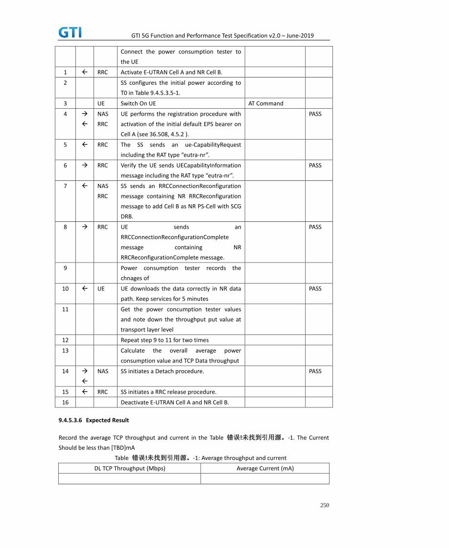
GTI 5G Function and Performance Test Specification v2.0 – June-2019
250
Connect the power consumption tester to
the UE
1 RRC Activate E-UTRAN Cell A and NR Cell B.
2 SS configures the initial power according to
T0 in Table 9.4.5.3.5-1.
3 UE Switch On UE AT Command
4
NAS
RRC
UE performs the registration procedure with
activation of the initial default EPS bearer on
Cell A (see 36.508, 4.5.2 ).
PASS
5 RRC The SS sends an ue-CapabilityRequest
including the RAT type “eutra-nr”.
6 RRC Verify the UE sends UECapabilityInformation
message including the RAT type “eutra-nr”.
PASS
7 NAS
RRC
SS sends an RRCConnectionReconfiguration
message containing NR RRCReconfiguration
message to add Cell B as NR PS-Cell with SCG
DRB.
8 RRC UE sends an
RRCConnectionReconfigurationComplete
message containing NR
RRCReconfigurationComplete message.
PASS
9 Power consumption tester records the
chnages of
10 UE UE downloads the data correctly in NR data
path. Keep services for 5 minutes
PASS
11 Get the power concumption tester values
and note down the throughput put value at
transport layer level
12 Repeat step 9 to 11 for two times
13 Calculate the overall average power
consumption value and TCP Data throughput
14
NAS SS initiates a Detach procedure. PASS
15 RRC SS initiates a RRC release procedure.
16 Deactivate E-UTRAN Cell A and NR Cell B.
9.4.5.3.6 Expected Result
Record the average TCP throughput and current in the Table 错误!未找到引用源。-1. The Current
Should be less than [TBD]mA
Table 错误!未找到引用源。-1: Average throughput and current
DL TCP Throughput (Mbps) Average Current (mA)

GTI 5G Function and Performance Test Specification v2.0 – June-2019
251
9.4.5.4 Power Consumption with DL Data Transfer, NSA (MCG & SCG – 256 QAM)
9.4.5.4.1 Test Purpose
Setup a MCG & SCG data bearer with with typical transmit level in a NSA cell. Measure the power
consumption when UE receives TCP data
9.4.5.4.2 Reference specification
TS 36.508, TS 38.331, TS 38.300
9.4.5.4.3 Applicability
This test applies to Type 1 and Type 3 devices as described in clause 4.2.
9.4.5.4.4 Test conditions
[SS configuration]
Cell A is E-UTRAN Cell, CellB is a NR Cell.
Cell A supports NSA
E-UTRAN Cell A
Cell Id=01 TAC = 01
MCC-MNC = 460-00
EARFCN= f1
rootSequenceIndex = 0
Reference Signal EPRE= -85 dBm/15kHz
RB Allocation DL = Full
DL Modulation / Coding = 27
P_Max = 0 dBm
DL 256 QAM = TRUE
upperLayerIndication-r15=true
DL MIMO = 2X2
NR Cell B
Cell Id=02 TAC = 01
MCC = 460 MNC = 00
NR-ARFCN= f1
SS/PBCH SSS EPRE = -125 dBm/30kHz
RB Allocation DL = Full
DL Modulation / Coding = 27
mcs-Table in PDSCH-Config = qam256
P_Max = 0 dBm
DL MIMO = 4X4
[UE configuration]

GTI 5G Function and Performance Test Specification v2.0 – June-2019
252
The test UICC with USIM should be inserted
The UE is in AUTOMATIC network selection mode.
UE works in NSA mode.
[Initial conditions]
SS
E-UTRAN Cell A is not active
NR Cell B is not active
The test shall be performed under ideal radio conditions.
UE
UE is powered off
9.4.5.4.5 Test procedure
Table 9.4.5.4.5-1: Time of cell power level and parameter changes
Time E-UTRAN Cell A NR Cell C Remark
T0 -85 -90
PREAMBLE
1. Activate E-UTRAN Cell A, NR Cell B.The SS configures the corresponding Master Information
Block and System Information Block broadcast.
2. The SS configures the initial power according to T0 in Table 9.4.5.4.5-1.
3. The UE is powered ON.
4. The UE performs the registration procedure with activation of the initial default EPS bearer
on Cell A (see 36.508, 4.5.2 ).
5. The SS sends an ue-CapabilityRequest including the RAT type “eutra-nr”.
6. Verify the UE sends UECapabilityInformation message including the RAT type “eutra-nr”.
7. The SS sends an RRCConnectionReconfiguration message containing NR RRCReconfiguration
message to add Cell B as NR PS-Cell with SCG DRB in addition with MCG bearer.
8. The UE sends an RRCConnectionReconfigurationComplete message containing NR
RRCReconfigurationComplete message.
MAIN BODY
9. The power consumption tester records the changes of current.
10. Setup a TCP session and verify that UE uploads data correctly. Verify that data transfer
happening in both MCG and SCG bearers. Keep the service for 5 minutes
11. Get the value of power consumption tester during step 10 and calculate the average
throughput at transport layer
12. Repeat Step 9 to 11 for two more time
13. Calculate the overall average power consumption and throughput at the transpport layer
POSTAMBLE
14. The SS initiates a Detach procedure.
15. The SS initiates a RRC release procedure.

GTI 5G Function and Performance Test Specification v2.0 – June-2019
253
16. Deactivate E-UTRAN Cell A and NR Cell B.
Table 5.1.1.5-2: Message Sequence
Step Message Sequence Verdict
U-S Layer Message Specific Contents
Connect the power consumption tester to
the UE
1 RRC Activate E-UTRAN Cell A and NR Cell B.
2 SS configures the initial power according to
T0 in Table 9.4.5.4.5-1.
3 UE Switch On UE AT Command
4
NAS
RRC
UE performs the registration procedure with
activation of the initial default EPS bearer on
Cell A (see 36.508, 4.5.2 ).
PASS
5 RRC The SS sends an ue-CapabilityRequest
including the RAT type “eutra-nr”.
6 RRC Verify the UE sends UECapabilityInformation
message including the RAT type “eutra-nr”.
PASS
7 NAS
RRC
SS sends an RRCConnectionReconfiguration
message containing NR RRCReconfiguration
message to add Cell B as NR PS-Cell with SCG
DRB in addition with existing MCG DRB
8 RRC UE sends an
RRCConnectionReconfigurationComplete
message containing NR
RRCReconfigurationComplete message.
PASS
9 Power consumption tester records the
changes of current
10 UE UE downloads the data correctly in both
MCG and SCG data path. Keep services for 5
minutes
PASS
11 Get the power concumption tester values
and note down the throughput put value at
transport layer level
12 Repeat step 9 to 11 for two times
13 Calculate the overall average power
consumption value and TCP Data throughput
14
NAS SS initiates a Detach procedure. PASS
15 RRC SS initiates a RRC release procedure.
16 Deactivate E-UTRAN Cell A and NR Cell B.
9.4.5.4.6 Expected Result

GTI 5G Function and Performance Test Specification v2.0 – June-2019
254
Record the average TCP throughput and current in the Table 错误!未找到引用源。-1. Current Should
be less than [TBD]mA
Table 错误!未找到引用源。-1: Average throughput and current
Throughput (Mbps) Average
Current(mA) DL TCP Throughput DL MAC Throughput in MCG DL MAC Throughput in SCG
[TBD] [TBD] [TBD] [TBD]
9.4.6 Bi-direction Data Transmission, Power Consumption, NSA
9.4.6.1 Power Consumption with Bidirectional Data Transfer, NSA (SCG – 64 QAM)
9.4.6.1.1 Test Purpose
Setup a SCG bearer with NR as DL/UL data path with typical transmit level.. Measure the power
consumption when UE transmits and receives TCP data simultaneously with a power of 0 dBm
9.4.6.1.2 Reference specification
TS 36.508, TS 38.331, TS 38.300
9.4.6.1.3 Applicability
This test applies to Type 1 and Type 3 devices as described in clause 4.2.
9.4.6.1.4 Test conditions
[SS configuration]
Cell A is E-UTRAN Cell, CellB is a NR Cell.
Cell A supports NSA
E-UTRAN Cell A
Cell Id=01 TAC = 01
MCC-MNC = 460-00
EARFCN= f1
rootSequenceIndex = 0
Reference Signal EPRE= -85 dBm/15kHz
upperLayerIndication-r15=true
NR Cell B
Cell Id=02 TAC = 01
MCC = 460 MNC = 00
NR-ARFCN= f1
SS/PBCH SSS EPRE = -125 dBm/30kHz
RB Allocation UL = Full
RB Allocation DL = Full
UL Modulation / Coding = 28

GTI 5G Function and Performance Test Specification v2.0 – June-2019
255
mcs-Table in PUSCH-Config = qam64
DL Modulation / Coding = 28
mcs-Table in PDSCH-Config = qam64
P_Max = 0 dBm
DL MIMO = 4X4
[UE configuration]
The test UICC with USIM should be inserted
The UE is in AUTOMATIC network selection mode.
UE works in NSA mode.
[Initial conditions]
SS
E-UTRAN Cell A is not active
NR Cell B is not active
The test shall be performed under ideal radio conditions.
UE
UE is powered off
9.4.6.1.5 Test procedure
Table 9.4.6.1.55.1.1.5-1: Time of cell power level and parameter changes
Time E-UTRAN Cell A NR Cell C Remark
T0 -85 -90
PREAMBLE
1. Activate E-UTRAN Cell A, NR Cell B.The SS configures the corresponding Master Information
Block and System Information Block broadcast.
2. The SS configures the initial power according to T0 in Table 9.4.6.1.5-1.
3. The UE is powered ON.
4. The UE performs the registration procedure with activation of the initial default EPS bearer
on Cell A (see 36.508, 4.5.2 ).
5. The SS sends an ue-CapabilityRequest including the RAT type “eutra-nr”.
6. Verify the UE sends UECapabilityInformation message including the RAT type “eutra-nr”.
7. The SS sends an RRCConnectionReconfiguration message containing NR RRCReconfiguration
message to add Cell B as NR PS-Cell with SCG DRB.
8. The UE sends an RRCConnectionReconfigurationComplete message containing NR
RRCReconfigurationComplete message.
MAIN BODY
9. The power consumption tester records the changes of current.
10. Setup a TCP session and verify that UE downloads/uploads data simultaneously. Verify that
data transfer happening in NR data path. Verify that UE TX power meeting the requirement
in test conditions. Keep the service for 5 minutes
11. Get the value of power consumption tester during step 10 and calculate the average

GTI 5G Function and Performance Test Specification v2.0 – June-2019
256
throughput at transport layer
12. Repeat Step 9 to 11 for two more time
13. Calculate the overall average power consumption and throughput at the transport layer
POSTAMBLE
14. The SS initiates a Detach procedure.
15. The SS initiates a RRC release procedure.
16. Deactivate E-UTRAN Cell A and NR Cell B.
Table 5.1.1.5-2: Message Sequence
Step Message Sequence Verdict
U-S Layer Message Specific Contents
Connect the power consumption tester to
the UE
1 RRC Activate E-UTRAN Cell A and NR Cell B.
2 SS configures the initial power according to
T0 in Table 9.4.6.1.5-1.
3 UE Switch On UE AT Command
4
NAS
RRC
UE performs the registration procedure with
activation of the initial default EPS bearer on
Cell A (see 36.508, 4.5.2 ).
PASS
5 RRC The SS sends an ue-CapabilityRequest
including the RAT type “eutra-nr”.
6 RRC Verify the UE sends UECapabilityInformation
message including the RAT type “eutra-nr”.
PASS
7 NAS
RRC
SS sends an RRCConnectionReconfiguration
message containing NR RRCReconfiguration
message to add Cell B as NR PS-Cell with SCG
DRB.
8 RRC UE sends an
RRCConnectionReconfigurationComplete
message containing NR
RRCReconfigurationComplete message.
PASS
9 Power consumption tester records the
chnages of current a
10 UE UE downloads/uploads the data correctly in
NR data path. Keep services for 5 minutes
PASS
11 Get the power concumption tester values
and note down the throughput value at
transport layer
12 Repeat step 9 to 11 for two times
13 Calculate the overall average power
consumption value and TCP Data throughput

GTI 5G Function and Performance Test Specification v2.0 – June-2019
257
14
NAS SS initiates a Detach procedure. PASS
15 RRC SS initiates a RRC release procedure.
16 Deactivate E-UTRAN Cell A and NR Cell B.
9.4.6.1.6 Expected Result
Record the average TCP throughput and current in the Table 错误!未找到引用源。-1. The Current
Should be less than [TBD]mA.
Table 错误!未找到引用源。-1: Average throughput and current
UL TCP Throughput (Mbps) DL TCP Throughput (Mbps) Average Current (mA)
[TBD] [TBD] [TBD]
9.4.6.2 Power Consumption with Bidirectional Data Transfer, NSA (MCG & SCG – 64
QAM)
9.4.6.2.1 Test Purpose
Setup a MCG & SCG data bearer with with typical transmit level in a NSA cell. Measure the power
consumption when UE transmits and receives TCP data simultaneously with a power of 0 dBm for
both LTE and NR cell
9.4.6.2.2 Reference specification
TS 36.508, TS 38.331, TS 38.300
9.4.6.2.3 Applicability
This test applies to Type 1 and Type 3 devices as described in clause 4.2.
9.4.6.2.4 Test conditions
[SS configuration]
Cell A is E-UTRAN Cell, CellB is a NR Cell.
Cell A supports NSA
E-UTRAN Cell A
Cell Id=01 TAC = 01
MCC-MNC = 460-00
EARFCN= f1
rootSequenceIndex = 0
Reference Signal EPRE= -85 dBm/15kHz
RB Allocation UL = Full
RB Allocation DL = Full
UL Modulation / Coding = 27
DL Modulation / Coding = 27

GTI 5G Function and Performance Test Specification v2.0 – June-2019
258
UL 64QAM = TRUE
DL 256QAM = FALSE
P_Max = 0 dBm
upperLayerIndication-r15=true
DL MIMO = 2X2
NR Cell B
Cell Id=02 TAC = 01
MCC = 460 MNC = 00
NR-ARFCN= f1
SS/PBCH SSS EPRE = -125 dBm/30kHz
RB Allocation UL = Full
RB Allocation DL = Full
UL Modulation / Coding = 28
mcs-Table in PUSCH-Config = qam64
DL Modulation / Coding = 28
mcs-Table in PDSCH-Config = qam64
P_Max = 0 dBm
DL MIMO = 4X4
[UE configuration]
The test UICC with USIM should be inserted
The UE is in AUTOMATIC network selection mode.
UE works in NSA mode.
[Initial conditions]
SS
E-UTRAN Cell A is not active
NR Cell B is not active
DL MCS = 22
UL MCS = 18
The test shall be performed under ideal radio conditions.
UE
UE is powered off
9.4.6.2.5 Test procedure
Table 5.1.1.5-1: Time of cell power level and parameter changes
Time E-UTRAN Cell A NR Cell C Remark
T0 -85 -90
PREAMBLE
1. Activate E-UTRAN Cell A, NR Cell B.The SS configures the corresponding Master Information
Block and System Information Block broadcast.
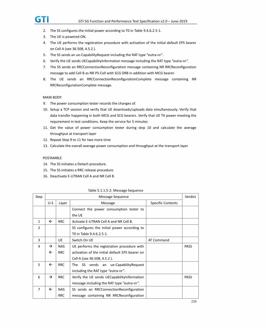
GTI 5G Function and Performance Test Specification v2.0 – June-2019
259
2. The SS configures the initial power according to T0 in Table 9.4.6.2.5-1.
3. The UE is powered ON.
4. The UE performs the registration procedure with activation of the initial default EPS bearer
on Cell A (see 36.508, 4.5.2 ).
5. The SS sends an ue-CapabilityRequest including the RAT type “eutra-nr”.
6. Verify the UE sends UECapabilityInformation message including the RAT type “eutra-nr”.
7. The SS sends an RRCConnectionReconfiguration message containing NR RRCReconfiguration
message to add Cell B as NR PS-Cell with SCG DRB in addition with MCG bearer.
8. The UE sends an RRCConnectionReconfigurationComplete message containing NR
RRCReconfigurationComplete message.
MAIN BODY
9. The power consumption tester records the changes of.
10. Setup a TCP session and verify that UE downloads/uploads data simultaneously. Verify that
data transfer happening in both MCG and SCG bearers. Verify that UE TX power meeting the
requirement in test conditions. Keep the service for 5 minutes
11. Get the value of power consumption tester during step 10 and calculate the average
throughput at transport layer
12. Repeat Step 9 to 11 for two more time
13. Calculate the overall average power consumption and throughput at the transport layer
POSTAMBLE
14. The SS initiates a Detach procedure.
15. The SS initiates a RRC release procedure.
16. Deactivate E-UTRAN Cell A and NR Cell B.
Table 5.1.1.5-2: Message Sequence
Step Message Sequence Verdict
U-S Layer Message Specific Contents
Connect the power consumption tester to
the UE
1 RRC Activate E-UTRAN Cell A and NR Cell B.
2 SS configures the initial power according to
T0 in Table 9.4.6.2.5-1.
3 UE Switch On UE AT Command
4
NAS
RRC
UE performs the registration procedure with
activation of the initial default EPS bearer on
Cell A (see 36.508, 4.5.2 ).
PASS
5 RRC The SS sends an ue-CapabilityRequest
including the RAT type “eutra-nr”.
6 RRC Verify the UE sends UECapabilityInformation
message including the RAT type “eutra-nr”.
PASS
7 NAS
RRC
SS sends an RRCConnectionReconfiguration
message containing NR RRCReconfiguration

GTI 5G Function and Performance Test Specification v2.0 – June-2019
260
message to add Cell B as NR PS-Cell with SCG
DRB in addition with existing MCG DRB
8 RRC UE sends an
RRCConnectionReconfigurationComplete
message containing NR
RRCReconfigurationComplete message.
PASS
9 Power consumption tester records the
changes of current
10 UE UE downloads/uploads the data correctly in
both MCG and SCG data path. Keep services
for 5 minutes
PASS
11 Get the power concumption tester values
and note down the throughput value at
transport layer
12 Repeat step 9 to 11 for two times
13 Calculate the overall average power
consumption value and TCP Data throughput
14
NAS SS initiates a Detach procedure. PASS
15 RRC SS initiates a RRC release procedure.
16 Deactivate E-UTRAN Cell A and NR Cell B.
9.4.6.2.6 Expected Result
Record the average TCP throughput and current in the Table 错误!未找到引用源。-1. The Current
Should be less than [TBD]mA
Table 错误!未找到引用源。-1: Average throughput and current
UL TCP Throughput (Mbps) DL TCP Throughput (Mbps) Average Current (mA)
9.4.6.3 Power Consumption with Bidirectional Data Transfer, NSA (SCG – 256 QAM)
9.4.6.3.1 Test Purpose
Setup a SCG bearer with NR as DL/UL data path with maximum transmit level. Measure the
power consumption when UE transmits and receives TCP data simultaneously with a power of 23 dBm
9.4.6.3.2 Reference specification
TS 36.508, TS 38.331, TS 38.300
9.4.6.3.3 Applicability
This test applies to Type 1 and Type 3 devices as described in clause 4.2.
9.4.6.3.4 Test conditions

GTI 5G Function and Performance Test Specification v2.0 – June-2019
261
[SS configuration]
Cell A is E-UTRAN Cell, CellB is a NR Cell.
Cell A supports NSA
E-UTRAN Cell A
Cell Id=01 TAC = 01
MCC-MNC = 460-00
EARFCN= f1
rootSequenceIndex = 0
Reference Signal EPRE= -85 dBm/15kHz
upperLayerIndication-r15=true
NR Cell B
Cell Id=02 TAC = 01
MCC = 460 MNC = 00
NR-ARFCN= f1
SS/PBCH SSS EPRE = -125 dBm/30kHz
RB Allocation UL = Full
RB Allocation DL = Full
UL Modulation / Coding = 27
mcs-Table in PUSCH-Config = qam256
DL Modulation / Coding = 27
mcs-Table in PDSCH-Config = qam256
P_Max = 23 dBm
DL MIMO = 4X4
[UE configuration]
The test UICC with USIM should be inserted
The UE is in AUTOMATIC network selection mode.
UE works in NSA mode.
[Initial conditions]
SS
E-UTRAN Cell A is not active
NR Cell B is not active
The test shall be performed under ideal radio conditions.
UE
UE is powered off
9.4.6.3.5 Test procedure
Table 5.1.1.5-1: Time of cell power level and parameter changes
Time E-UTRAN Cell A NR Cell C Remark
T0 -85 -90
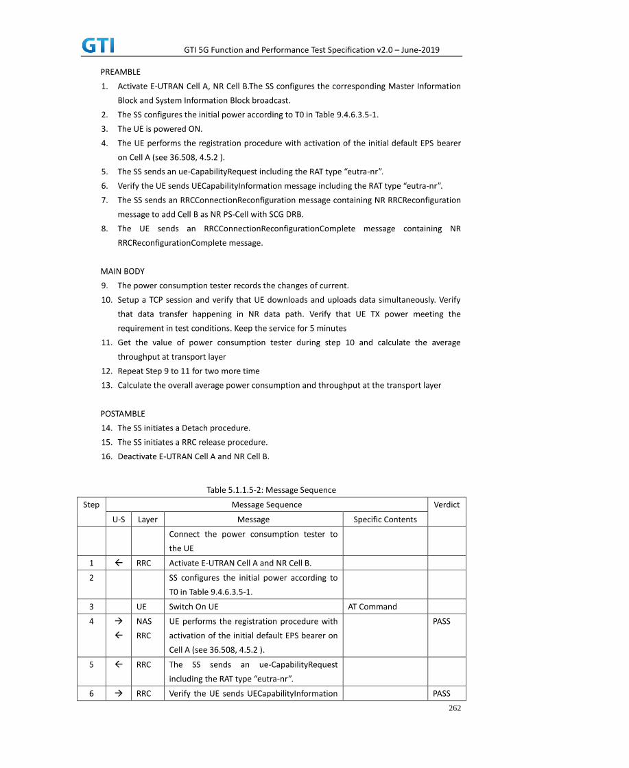
GTI 5G Function and Performance Test Specification v2.0 – June-2019
262
PREAMBLE
1. Activate E-UTRAN Cell A, NR Cell B.The SS configures the corresponding Master Information
Block and System Information Block broadcast.
2. The SS configures the initial power according to T0 in Table 9.4.6.3.5-1.
3. The UE is powered ON.
4. The UE performs the registration procedure with activation of the initial default EPS bearer
on Cell A (see 36.508, 4.5.2 ).
5. The SS sends an ue-CapabilityRequest including the RAT type “eutra-nr”.
6. Verify the UE sends UECapabilityInformation message including the RAT type “eutra-nr”.
7. The SS sends an RRCConnectionReconfiguration message containing NR RRCReconfiguration
message to add Cell B as NR PS-Cell with SCG DRB.
8. The UE sends an RRCConnectionReconfigurationComplete message containing NR
RRCReconfigurationComplete message.
MAIN BODY
9. The power consumption tester records the changes of current.
10. Setup a TCP session and verify that UE downloads and uploads data simultaneously. Verify
that data transfer happening in NR data path. Verify that UE TX power meeting the
requirement in test conditions. Keep the service for 5 minutes
11. Get the value of power consumption tester during step 10 and calculate the average
throughput at transport layer
12. Repeat Step 9 to 11 for two more time
13. Calculate the overall average power consumption and throughput at the transport layer
POSTAMBLE
14. The SS initiates a Detach procedure.
15. The SS initiates a RRC release procedure.
16. Deactivate E-UTRAN Cell A and NR Cell B.
Table 5.1.1.5-2: Message Sequence
Step Message Sequence Verdict
U-S Layer Message Specific Contents
Connect the power consumption tester to
the UE
1 RRC Activate E-UTRAN Cell A and NR Cell B.
2 SS configures the initial power according to
T0 in Table 9.4.6.3.5-1.
3 UE Switch On UE AT Command
4
NAS
RRC
UE performs the registration procedure with
activation of the initial default EPS bearer on
Cell A (see 36.508, 4.5.2 ).
PASS
5 RRC The SS sends an ue-CapabilityRequest
including the RAT type “eutra-nr”.
6 RRC Verify the UE sends UECapabilityInformation PASS

GTI 5G Function and Performance Test Specification v2.0 – June-2019
263
message including the RAT type “eutra-nr”.
7 NAS
RRC
SS sends an RRCConnectionReconfiguration
message containing NR RRCReconfiguration
message to add Cell B as NR PS-Cell with SCG
DRB.
8 RRC UE sends an
RRCConnectionReconfigurationComplete
message containing NR
RRCReconfigurationComplete message.
PASS
9 Power consumption tester records the
chnages of current
10 UE UE downloads/uploads the data correctly in
NR data path. Keep services for 5 minutes
PASS
11 Get the power concumption tester values
and note down the throughput value at
transport layer
12 Repeat step 9 to 11 for two times
13 Calculate the overall average power
consumption value and TCP Data throughput
14
NAS SS initiates a Detach procedure. PASS
15 RRC SS initiates a RRC release procedure.
16 Deactivate E-UTRAN Cell A and NR Cell B.
9.4.6.3.6 Expected Result
Record the average TCP throughput and current in the Table 错误!未找到引用源。-1. The Current
Should be less than [TBD]mA
Table 错误!未找到引用源。-1: Average throughput and current
UL TCP Throughput (Mbps) DL TCP Throughput (Mbps) Average Current (mA)
[TBD] [TBD] [TBD]
9.4.6.4 Power Consumption with UL Data Transfer, NSA (MCG & SCG – 256 QAM)
9.4.6.4.1 Test Purpose
Setup a MCG & SCG data bearer with with typical transmit level in a NSA cell. Measure the power
consumption when UE transmits and receives TCP data simultaneously with a power of 23 dBm for
both LTE and NR cell
9.4.6.4.2 Reference specification
TS 36.508, TS 38.331, TS 38.300
9.4.6.4.3 Applicability

GTI 5G Function and Performance Test Specification v2.0 – June-2019
264
This test applies to Type 1 and Type 3 devices as described in clause 4.2.
9.4.6.4.4 Test conditions
[SS configuration]
Cell A is E-UTRAN Cell, CellB is a NR Cell.
Cell A supports NSA
E-UTRAN Cell A
Cell Id=01 TAC = 01
MCC-MNC = 460-00
EARFCN= f1
rootSequenceIndex = 0
Reference Signal EPRE= -85 dBm/15kHz
RB Allocation UL = Full
RB Allocation DL = Full
UL Modulation / Coding = 27
DL Modulation / Coding = 27
UL 64QAM = TRUE
DL 256QAM = TRUE
P_Max = 23 dBm
upperLayerIndication-r15=true
DL MIMO = 2X2
NR Cell B
Cell Id=02 TAC = 01
MCC = 460 MNC = 00
NR-ARFCN= f1
SS/PBCH SSS EPRE = -125 dBm/30kHz
RB Allocation UL = Full
RB Allocation DL = Full
UL Modulation / Coding = 27
mcs-Table in PUSCH-Config = qam256
DL Modulation / Coding = 27
mcs-Table in PDSCH-Config = qam256
P_Max = 23 dBm
DL MIMO = 4X4
[UE configuration]
The test UICC with USIM should be inserted
The UE is in AUTOMATIC network selection mode.
UE works in NSA mode.
[Initial conditions]
SS

GTI 5G Function and Performance Test Specification v2.0 – June-2019
265
E-UTRAN Cell A is not active
NR Cell B is not active
The test shall be performed under ideal radio conditions.
UE
UE is powered off
9.4.6.4.5 Test procedure
Table 5.1.1.5-1: Time of cell power level and parameter changes
Time E-UTRAN Cell A NR Cell C Remark
T0 -85 -90
PREAMBLE
1. Activate E-UTRAN Cell A, NR Cell B.The SS configures the corresponding Master Information
Block and System Information Block broadcast.
2. The SS configures the initial power according to T0 in Table 9.4.6.4.5-1.
3. The UE is powered ON.
4. The UE performs the registration procedure with activation of the initial default EPS bearer
on Cell A (see 36.508, 4.5.2 ).
5. The SS sends an ue-CapabilityRequest including the RAT type “eutra-nr”.
6. Verify the UE sends UECapabilityInformation message including the RAT type “eutra-nr”.
7. The SS sends an RRCConnectionReconfiguration message containing NR RRCReconfiguration
message to add Cell B as NR PS-Cell with SCG DRB in addition with MCG bearer.
8. The UE sends an RRCConnectionReconfigurationComplete message containing NR
RRCReconfigurationComplete message.
MAIN BODY
9. The power consumption tester records the changes of current.
10. Setup a TCP session and verify that UE downloads and uploads data simultaneously. Verify
that data transfer happening in both MCG and SCG bearers. Verify that UE TX power meeting
the requirement in test conditions. Keep the service for 5 minutes
11. Get the value of power consumption tester during step 10 and calculate the average
throughput at transport layer
12. Repeat Step 9 to 11 for two more time
13. Calculate the overall average power consumption and throughput at the transport layer
POSTAMBLE
14. The SS initiates a Detach procedure.
15. The SS initiates a RRC release procedure.
16. Deactivate E-UTRAN Cell A and NR Cell B.
Table 5.1.1.5-2: Message Sequence
Step Message Sequence Verdict
U-S Layer Message Specific Contents

GTI 5G Function and Performance Test Specification v2.0 – June-2019
266
Connect the power consumption tester to
the UE
1 RRC Activate E-UTRAN Cell A and NR Cell B.
2 SS configures the initial power according to
T0 in Table 9.4.6.4.5-1.
3 UE Switch On UE AT Command
4
NAS
RRC
UE performs the registration procedure with
activation of the initial default EPS bearer on
Cell A (see 36.508, 4.5.2 ).
PASS
5 RRC The SS sends an ue-CapabilityRequest
including the RAT type “eutra-nr”.
6 RRC Verify the UE sends UECapabilityInformation
message including the RAT type “eutra-nr”.
PASS
7 NAS
RRC
SS sends an RRCConnectionReconfiguration
message containing NR RRCReconfiguration
message to add Cell B as NR PS-Cell with SCG
DRB in addition with existing MCG DRB
8 RRC UE sends an
RRCConnectionReconfigurationComplete
message containing NR
RRCReconfigurationComplete message.
PASS
9 Power consumption tester records the
changes of current
10 UE UE downloads/uploads the data correctly in
both MCG and SCG data path. Keep services
for 5 minutes
PASS
11 Get the power concumption tester values
and note down the throughput value at
transport layer
12 Repeat step 9 to 11 for two times
13 Calculate the overall average power
consumption value and TCP Data throughput
14
NAS SS initiates a Detach procedure. PASS
15 RRC SS initiates a RRC release procedure.
16 Deactivate E-UTRAN Cell A and NR Cell B.
9.4.6.4.6 Expected Result
Record the average TCP throughput and current in the Table 错误!未找到引用源。-1. The Current
Should be less than [TBD]mA
Table 错误!未找到引用源。-1: Average throughput and current
UL TCP Throughput (Mbps) DL TCP Throughput (Mbps) Average Current (mA)
[TBD] [TBD] [TBD]

GTI 5G Function and Performance Test Specification v2.0 – June-2019
267
9.5 Power Consumption - Inactive Mode
9.5.1 RRC Inactive Mode, Power Consumption, SA
9.5.1.1 Test Purpose
When UE enters RRC_Inactive State after Registering in NR cell, Measure the power consumption.
9.5.1.2 Reference specification
TS 38.304, TS 38.331, TS 38.300
9.5.1.3 Applicability
This test applies to the device that supports SA or SA+NSA.
9.5.1.4 Test conditions
[SS configuration]
Cell A is a NR Cell.
Cell A supports only SA
NR Cell A
Cell Id=01 TAC = 01
MCC = 460 MNC = 00
NR Band = n41
NR-ARFCN= f1
Bandwidth = 100 MHz
SS/PBCH SSS EPRE = -125 dBm/30kHz
t380 = min10
[UE configuration]
The test UICC with USIM should be inserted
The UE is in AUTOMATIC network selection mode.
UE works in SA mode.
[Initial conditions]
SS
NR Cell A is not active
The test shall be performed under ideal radio conditions.
UE
UE is powered off
9.5.1.5 Test procedure
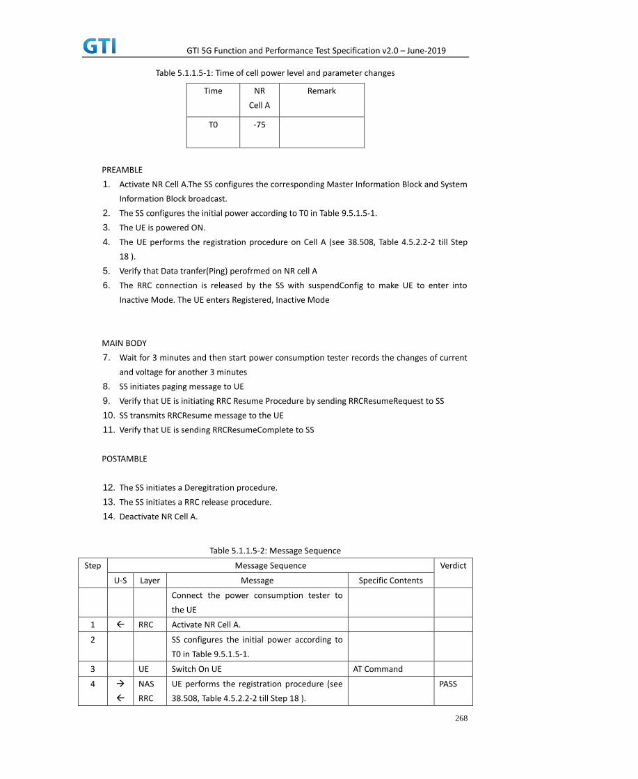
GTI 5G Function and Performance Test Specification v2.0 – June-2019
268
Table 5.1.1.5-1: Time of cell power level and parameter changes
Time NR
Cell A
Remark
T0 -75
PREAMBLE
1. Activate NR Cell A.The SS configures the corresponding Master Information Block and System
Information Block broadcast.
2. The SS configures the initial power according to T0 in Table 9.5.1.5-1.
3. The UE is powered ON.
4. The UE performs the registration procedure on Cell A (see 38.508, Table 4.5.2.2-2 till Step
18 ).
5. Verify that Data tranfer(Ping) perofrmed on NR cell A
6. The RRC connection is released by the SS with suspendConfig to make UE to enter into
Inactive Mode. The UE enters Registered, Inactive Mode
MAIN BODY
7. Wait for 3 minutes and then start power consumption tester records the changes of current
and voltage for another 3 minutes
8. SS initiates paging message to UE
9. Verify that UE is initiating RRC Resume Procedure by sending RRCResumeRequest to SS
10. SS transmits RRCResume message to the UE
11. Verify that UE is sending RRCResumeComplete to SS
POSTAMBLE
12. The SS initiates a Deregitration procedure.
13. The SS initiates a RRC release procedure.
14. Deactivate NR Cell A.
Table 5.1.1.5-2: Message Sequence
Step Message Sequence Verdict
U-S Layer Message Specific Contents
Connect the power consumption tester to
the UE
1 RRC Activate NR Cell A.
2 SS configures the initial power according to
T0 in Table 9.5.1.5-1.
3 UE Switch On UE AT Command
4
NAS
RRC
UE performs the registration procedure (see
38.508, Table 4.5.2.2-2 till Step 18 ).
PASS

GTI 5G Function and Performance Test Specification v2.0 – June-2019
269
5 Verify the data transmission is performed
successfully on NR Cell A.
PASS
6 RRC The RRC connection is released by the SS
with suspendConfig.
7 Wait for 3 minutes and then start power
consumption tester records the changes of
current and voltage for another 3 minutes
8 RRC Paging
9 RRC RRCResumeRequest PASS
10 RRC RRCResume
11 RRC RRCResumeComplete PASS
12
NAS SS initiates a Deregitration procedure. PASS
13 RRC SS initiates a RRC release procedure.
14 Deactivate NR Cell A.
9.5.1.6 Expected Result
The Current Should be less than [TBD]mA
9.5.2 RRC Inactive Mode – RNA Update Timer Expiry, Power Consumption
9.5.2.1 Test Purpose
When RNA Update timer expires in RRC Inactive Mode verify that UE initiates RRC Connection
Resume Procedure for RNA Update and measure the power consumption
9.5.2.2 Reference specification
TS 38.304, TS 38.331, TS 38.300
9.5.2.3 Applicability
This test applies to the device that supports SA or SA+NSA.
9.5.2.4 Test conditions
[SS configuration]
Cell A is a NR Cell.
Cell A supports only SA
NR Cell A
Cell Id=01 TAC = 01
MCC = 460 MNC = 00

GTI 5G Function and Performance Test Specification v2.0 – June-2019
270
NR Band = n41
NR-ARFCN= f1
Bandwidth = 100 MHz
SS/PBCH SSS EPRE = -125 dBm/30kHz
T380 = min5
[UE configuration]
The test UICC with USIM should be inserted
The UE is in AUTOMATIC network selection mode.
UE works in SA mode.
[Initial conditions]
SS
NR Cell A is not active
The test shall be performed under ideal radio conditions.
UE
UE is powered off
9.5.2.5 Test procedure
Table 5.1.1.55-1: Time of cell power level and parameter changes
Time NR
Cell A
Remark
T0 -75
PREAMBLE
1. Activate NR Cell A.The SS configures the corresponding Master Information Block and System
Information Block broadcast.
2. The SS configures the initial power according to T0 in Table 9.5.2.5-1.
3. The UE is powered ON.
4. The UE performs the registration procedure on Cell A (see 38.508, Table 4.5.2.2-2 till Step
18 ).
5. Verify that Data tranfer(Ping) perofrmed on NR cell A
MAIN BODY
6. The RRC connection is released by the SS with suspendConfig. The UE enters Registered,
Inactive Mode
7. Start the power consumption tester which records the changes of current and Voltage Wait
for t380 timer duration expiry

GTI 5G Function and Performance Test Specification v2.0 – June-2019
271
8. After t380 expiry Verify that UE is initiating RRC Resume Procedure by sending
RRCResumeRequest with resume cause set as ‘rna-Update’ to SS
9. SS transmits RRCResume message to the UE
10. Verify that UE is sending RRCResumeComplete to SS
11. Get the value of power consumption tester during Step 8 to Step 9
12. Verify that Data tranfer(Ping) perofrmed on NR cell A
POSTAMBLE
13. The SS initiates a Deregitration procedure.
14. The SS initiates a RRC release procedure.
15. Deactivate NR Cell A.
Table 5.1.1.5-2: Message Sequence
Step Message Sequence Verdict
U-S Layer Message Specific Contents
Connect the power consumption tester to
the UE
1 RRC Activate NR Cell A.
2 SS configures the initial power according to
T0 in Table 9.5.2.5-1.
3 UE Switch On UE AT Command
4
NAS
RRC
UE performs the registration procedure (see
38.508, Table 4.5.2.2-2 till Step 18 ).
PASS
5 Verify the data transmission is performed
successfully on NR Cell A.
PASS
6 RRC The RRC connection is released by the SS
with suspendConfig.
7 Start Power consumption tester to record the
chnages of current and voltage and Wait for
t380 timer duration to expire
8 RRC RRCResumeRequest with resume cause
rna-update
PASS
9 RRC RRCResume
10 RRC RRCResumeComplete PASS
11 Verify the data transmission is performed
successfully on NR Cell A.
PASS
12
NAS SS initiates a Deregitration procedure. PASS
13 RRC SS initiates a RRC release procedure.
14 Deactivate NR Cell A.
9.5.2.6 Expected Result

GTI 5G Function and Performance Test Specification v2.0 – June-2019
272
The Current Should be less than [TBD]mA
9.6 BWP, Power Consumption
9.6.1 Downlink Data Transmission with different BWP, Power Consumption, SA
9.6.1.1 Test Purpose
To measure UE power consumption of donwlink data transmission with different BWP
configuration in SA mode.
9.6.1.2 Reference specification
TS 38.321, clause 5.15
TS 38.331, clause 5.2.1, clause 5.3.5.3
9.6.1.3 Applicability
This test applies to Type 1 and Type 2 devices as described in clause 4.2
9.6.1.4 Test conditions
[SS configuration]
Cell A is a NR Cell.
Cell A supports only SA
NR Cell A
Cell Id=01 TAC = 01
MCC = 460 MNC = 00
NR-ARFCN= f1
SS/PBCH SSS EPRE = -80 dBm/30kHz
DL Modulation / Coding= 20
DL RB=50
mcs-Table in PDSCH-Config = qam64
UL TX Power=0dBm
[UE configuration]
The test UICC with USIM should be inserted
The UE is in AUTOMATIC network selection mode.
UE works in SA mode.
[Initial conditions]
SS
NR Cell A is not active
The test shall be performed under ideal radio conditions.

GTI 5G Function and Performance Test Specification v2.0 – June-2019
273
UE
UE is powered off
9.6.1.5 Test procedure
PREAMBLE
1. Activate NR Cell A. The SS configures the corresponding Master Information Block and
System Information Block broadcast.
2. The SS configures the initial power according to test conditions.
3. The UE is powered ON.
4. The UE performs the registration procedure on Cell A (see 38.508, Table 4.5.2.2-2 till Step
15 ).
MAIN BODY
5. SS transmits NR RRCConnectionReconfiguration to configure DL BWP and UL BWP with
BWP-ID=1 and bandwidth=100MHz. Refer to Table 9.6.1.5-1 and Table 9.6.1.5-2 for BWP
parameters
6. UE transmits RRCConnectionReconfigurationComplete
7. Setup donwlink TCP session and verify that UE downloads data correctly by using BWP-ID =
1.
8. Start power consumption tester records the changes of current for 3 minutes
9. Stop power consumption measurement. Stop data transmission
10. SS sends RRCRelease. UE returns to Idle mode.
11. Wait for 2 minutes. The SS transmits a Paging message. UE is in RRCConnected mode.
12. SS transmits NR RRCConnectionReconfiguration to configure DL BWP and UL BWP with
BWP-ID=1 and bandwidth=20MHz. Refer to Table 9.6.1.5-1 and Table 9.6.1.5-3 for BWP
parameters.
13. Setup downlink TCP session and verify that UE downloads data correctly by using BWP-ID =
1.
14. Start power consumption tester records the changes of current for 3 minutes
15. Stop power consumption measurement. Stop data transmission
POSTAMBLE
16. The SS initiates a Deregitration procedure.
17. The SS initiates a RRC release procedure.
18. Deactivate NR Cell A.
Table 9.6.1.5-1: BWP configuration
Derivation Path: TS 38.508-1 [4], Table 4.6.3-167
Information Element Value/remark Comment
ServingCellConfig ::= SEQUENCE {
…….. ……..
downlinkBWP-ToReleaseList Not Present
downlinkBWP-ToAddModList SEQUENCE (SIZE (1))
OF BWP-Downlink
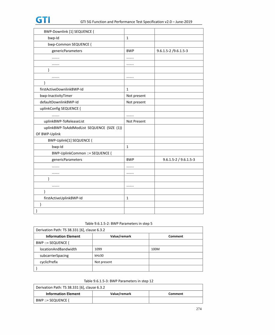
GTI 5G Function and Performance Test Specification v2.0 – June-2019
274
BWP-Downlink [1] SEQUENCE {
bwp-Id 1
bwp-Common SEQUENCE {
genericParameters BWP 9.6.1.5-2 /9.6.1.5-3
…….. ……..
…….. ……..
}
…….. ……..
}
firstActiveDownlinkBWP-Id 1
bwp-InactivityTimer Not present
defaultDownlinkBWP-Id Not present
uplinkConfig SEQUENCE {
…….. ……..
uplinkBWP-ToReleaseList Not Present
uplinkBWP-ToAddModList SEQUENCE (SIZE (1))
OF BWP-Uplink
BWP-Uplink[1] SEQUENCE {
bwp-Id 1
BWP-UplinkCommon ::= SEQUENCE {
genericParameters BWP 9.6.1.5-2 / 9.6.1.5-3
…….. ……..
…….. ……..
}
…….. ……..
}
firstActiveUplinkBWP-Id 1
}
}
Table 9.6.1.5-2: BWP Parameters in step 5
Derivation Path: TS 38.331 [6], clause 6.3.2
Information Element Value/remark Comment
BWP ::= SEQUENCE {
locationAndBandwidth 1099 100M
subcarrierSpacing kHz30
cyclicPrefix Not present
}
Table 9.6.1.5-3: BWP Parameters in step 12
Derivation Path: TS 38.331 [6], clause 6.3.2
Information Element Value/remark Comment
BWP ::= SEQUENCE {

GTI 5G Function and Performance Test Specification v2.0 – June-2019
275
locationAndBandwidth 13750 20M
subcarrierSpacing kHz30
cyclicPrefix Not present
}
9.6.1.6 Expected Result
Record the average current in step 8 and step 14.
Table 9.2.1.2.6-1: Test Results
Test Step Average Current(mA)
Step 8: BWP=100MHz
Step 14: BWP=20MHz
9.6.2 Uplink Data Transmission with different BWP, Power Consumption, SA
9.6.2.1 Test Purpose
To measure UE power consumption of uplink data transmission with different BWP configuration
in SA mode.
9.6.2.2 Reference specification
TS 38.321, clause 5.15
TS 38.331, clause 5.2.1, clause 5.3.5.3
9.6.2.3 Applicability
This test applies to Type 1 and Type 2 devices as described in clause 4.2
9.6.2.4 Test conditions
[SS configuration]
Cell A is a NR Cell.
Cell A supports only SA
NR Cell A
Cell Id=01 TAC = 01
MCC = 460 MNC = 00
NR-ARFCN= f1
SS/PBCH SSS EPRE = -80 dBm/30kHz
UL Modulation / Coding= 20
UL RB=50
mcs-Table in PUSCH-Config = qam64

GTI 5G Function and Performance Test Specification v2.0 – June-2019
276
UL TX Power=0dBm
[UE configuration]
The test UICC with USIM should be inserted
The UE is in AUTOMATIC network selection mode.
UE works in SA mode.
[Initial conditions]
SS
NR Cell A is not active
The test shall be performed under ideal radio conditions.
UE
UE is powered off
9.6.2.5 Test procedure
PREAMBLE
1. Activate NR Cell A. The SS configures the corresponding Master Information Block and
System Information Block broadcast.
2. The SS configures the initial power according to test conditions.
3. The UE is powered ON.
4. The UE performs the registration procedure on Cell A (see 38.508, Table 4.5.2.2-2 till Step
15 ).
MAIN BODY
5. SS transmits NR RRCConnectionReconfiguration to configure DL BWP and UL BWP with
BWP-ID=1 and bandwidth=100MHz. Refer to Table 9.6.1.5-1 and Table 9.6.1.5-2 for BWP
parameters
6. UE transmits RRCConnectionReconfigurationComplete
7. Setup uplink TCP session and verify that UE transmits data correctly by using BWP-ID = 1.
8. Start power consumption tester records the changes of current for 3 minutes
9. Stop power consumption measurement. Stop data transmission
10. SS sends RRC Release. UE returns to Idle mode.
11. Wait for 2 minutes. The SS transmits a Paging message. UE is in RRCConnected mode.
12. SS transmits NR RRCConnectionReconfiguration to configure DL BWP and UL BWP with
BWP-ID=1 and bandwidth=20MHz. Refer to Table 9.6.1.5-1 and Table 9.6.1.5-3 for BWP
parameters.
13. Setup uplink TCP session and verify that UE transmits data correctly by using BWP-ID = 1.
14. Start power consumption tester records the changes of current for 3 minutes
15. Stop power consumption measurement. Stop data transmission
POSTAMBLE
16. The SS initiates a Deregitration procedure.
17. The SS initiates a RRC release procedure.
18. Deactivate NR Cell A.

GTI 5G Function and Performance Test Specification v2.0 – June-2019
277
9.6.2.6 Expected Result
Record the average current in step 8 and step 14.
Table 9.2.1.2.6-1: Test Results
Test Step Average Current(mA)
Step 8: BWP=100MHz
Step 14: BWP=20MHz
9.6.3 Downlink Data Transmission with different BWP, Power Consumption, NSA
9.6.3.1 Test Purpose
To measure UE power consumption of donwlink data transmission with different BWP
configuration in NSA mode.
9.6.3.2 Reference specification
TS 38.321, clause 5.15
TS 38.331, clause 5.2.1, clause 5.3.5.3
9.6.3.3 Applicability
This test applies to Type 1 and Type 3 devices as described in clause 4.2
9.6.3.4 Test conditions
[SS configuration]
Cell A is E-UTRAN Cell, CellB is a NR Cell.
Cell A supports NSA
E-UTRAN Cell A
Cell Id=01 TAC = 01
MCC-MNC = 460-00
EARFCN= f1
rootSequenceIndex = 0
Reference Signal EPRE= -85 dBm/15kHz
upperLayerIndication-r15=true
NR Cell B
Cell Id=02 TAC = 01
NR-ARFCN= f1
SS/PBCH SSS EPRE = -80 dBm/30kHz
DL Modulation / Coding= 20
DL RB=50
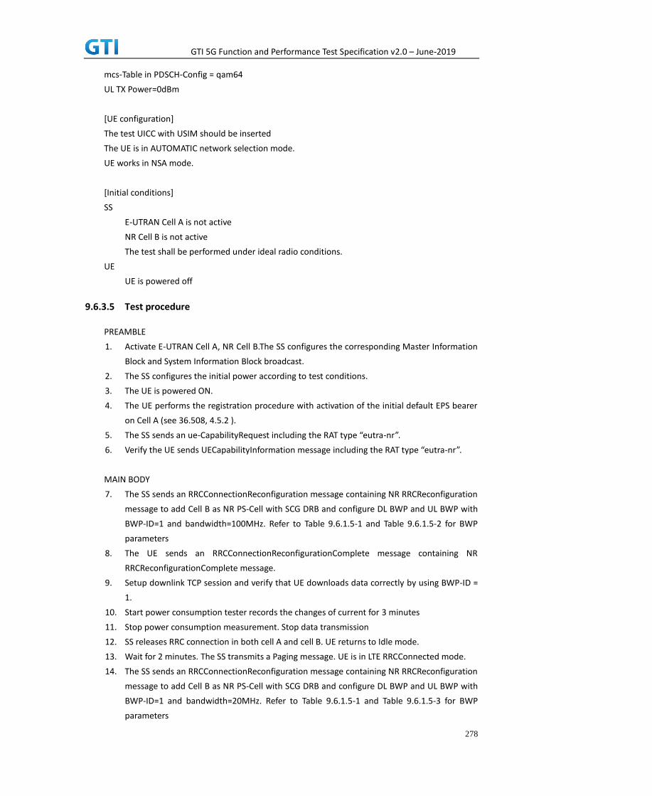
GTI 5G Function and Performance Test Specification v2.0 – June-2019
278
mcs-Table in PDSCH-Config = qam64
UL TX Power=0dBm
[UE configuration]
The test UICC with USIM should be inserted
The UE is in AUTOMATIC network selection mode.
UE works in NSA mode.
[Initial conditions]
SS
E-UTRAN Cell A is not active
NR Cell B is not active
The test shall be performed under ideal radio conditions.
UE
UE is powered off
9.6.3.5 Test procedure
PREAMBLE
1. Activate E-UTRAN Cell A, NR Cell B.The SS configures the corresponding Master Information
Block and System Information Block broadcast.
2. The SS configures the initial power according to test conditions.
3. The UE is powered ON.
4. The UE performs the registration procedure with activation of the initial default EPS bearer
on Cell A (see 36.508, 4.5.2 ).
5. The SS sends an ue-CapabilityRequest including the RAT type “eutra-nr”.
6. Verify the UE sends UECapabilityInformation message including the RAT type “eutra-nr”.
MAIN BODY
7. The SS sends an RRCConnectionReconfiguration message containing NR RRCReconfiguration
message to add Cell B as NR PS-Cell with SCG DRB and configure DL BWP and UL BWP with
BWP-ID=1 and bandwidth=100MHz. Refer to Table 9.6.1.5-1 and Table 9.6.1.5-2 for BWP
parameters
8. The UE sends an RRCConnectionReconfigurationComplete message containing NR
RRCReconfigurationComplete message.
9. Setup downlink TCP session and verify that UE downloads data correctly by using BWP-ID =
1.
10. Start power consumption tester records the changes of current for 3 minutes
11. Stop power consumption measurement. Stop data transmission
12. SS releases RRC connection in both cell A and cell B. UE returns to Idle mode.
13. Wait for 2 minutes. The SS transmits a Paging message. UE is in LTE RRCConnected mode.
14. The SS sends an RRCConnectionReconfiguration message containing NR RRCReconfiguration
message to add Cell B as NR PS-Cell with SCG DRB and configure DL BWP and UL BWP with
BWP-ID=1 and bandwidth=20MHz. Refer to Table 9.6.1.5-1 and Table 9.6.1.5-3 for BWP
parameters

GTI 5G Function and Performance Test Specification v2.0 – June-2019
279
15. Setup downlink TCP session and verify that UE downloads data correctly by using BWP-ID =
1.
16. Start power consumption tester records the changes of current for 3 minutes
17. Stop power consumption measurement. Stop data transmission
POSTAMBLE
18. The SS initiates a Detach procedure.
19. The SS initiates a RRC release procedure.
20. Deactivate E-UTRAN Cell A and NR Cell B.
9.6.3.6 Expected Result
Record the average current in step 8 and step 14.
Table 9.2.1.2.6-1: Test Results
Test Step Average Current(mA)
Step 10: BWP=100MHz
Step 16: BWP=20MHz
9.6.4 Uplink Data Transmission with different BWP, Power Consumption, NSA
9.6.4.1 Test Purpose
To measure UE power consumption of uplink data transmission with different BWP configuration
in NSA mode.
9.6.4.2 Reference specification
TS 38.321, clause 5.15
TS 38.331, clause 5.2.1, clause 5.3.5.3
9.6.4.3 Applicability
This test applies to Type 1 and Type 3 devices as described in clause 4.2
9.6.4.4 Test conditions
[SS configuration]
Cell A is E-UTRAN Cell, CellB is a NR Cell.
Cell A supports NSA
E-UTRAN Cell A
Cell Id=01 TAC = 01
MCC-MNC = 460-00
EARFCN= f1
rootSequenceIndex = 0
Reference Signal EPRE= -85 dBm/15kHz
upperLayerIndication-r15=true

GTI 5G Function and Performance Test Specification v2.0 – June-2019
280
NR Cell B
Cell Id=02 TAC = 01
NR-ARFCN= f1
SS/PBCH SSS EPRE = -80 dBm/30kHz
UL Modulation / Coding= 20
UL RB=50
mcs-Table in PUSCH-Config = qam64
UL TX Power=0dBm
[UE configuration]
The test UICC with USIM should be inserted
The UE is in AUTOMATIC network selection mode.
UE works in NSA mode.
[Initial conditions]
SS
E-UTRAN Cell A is not active
NR Cell B is not active
The test shall be performed under ideal radio conditions.
UE
UE is powered off
9.6.4.5 Test procedure
PREAMBLE
1. Activate E-UTRAN Cell A, NR Cell B.The SS configures the corresponding Master Information
Block and System Information Block broadcast.
2. The SS configures the initial power according to test conditions.
3. The UE is powered ON.
4. The UE performs the registration procedure with activation of the initial default EPS bearer
on Cell A (see 36.508, 4.5.2 ).
5. The SS sends an ue-CapabilityRequest including the RAT type “eutra-nr”.
6. Verify the UE sends UECapabilityInformation message including the RAT type “eutra-nr”.
MAIN BODY
7. The SS sends an RRCConnectionReconfiguration message containing NR RRCReconfiguration
message to add Cell B as NR PS-Cell with SCG DRB and configure DL BWP and UL BWP with
BWP-ID=1 and bandwidth=100MHz. Refer to Table 9.6.1.5-1 and Table 9.6.1.5-2 for BWP
parameters
8. The UE sends an RRCConnectionReconfigurationComplete message containing NR
RRCReconfigurationComplete message.
9. Setup uplink TCP session and verify that UE transmits data correctly by using BWP-ID = 1.
10. Start power consumption tester records the changes of current for 3 minutes
11. Stop power consumption measurement. Stop data transmission

GTI 5G Function and Performance Test Specification v2.0 – June-2019
281
12. SS releases RRC connection in both cell A and cell B. UE returns to Idle mode.
13. Wait for 2 minutes. The SS transmits a Paging message. UE is in LTE RRCConnected mode.
14. The SS sends an RRCConnectionReconfiguration message containing NR RRCReconfiguration
message to add Cell B as NR PS-Cell with SCG DRB and configure DL BWP and UL BWP with
BWP-ID=1 and bandwidth=20MHz. Refer to Table 9.6.1.5-1 and Table 9.6.1.5-3 for BWP
parameters
15. Setup uplink TCP session and verify that UE downloads data correctly by using BWP-ID = 1.
16. Start power consumption tester records the changes of current for 3 minutes
17. Stop power consumption measurement. Stop data transmission
POSTAMBLE
18. The SS initiates a Detach procedure.
19. The SS initiates a RRC release procedure.
20. Deactivate E-UTRAN Cell A and NR Cell B.
9.6.4.6 Expected Result
Record the average current in step 8 and step 14.
Table 9.2.1.2.6-1: Test Results
Test Step Average Current(mA)
Step 10: BWP=100MHz
Step 16: BWP=20MHz
10 Data Throughput
10.1 Downlink TCP Throughput
10.1.1 DL Throughput under static channel, DL 256QAM, DL4*4 MIMO
10.1.1.1 Test Purpose
To measure the UE application layer downlink performance while downloading TCP based data in
Conducted, Static Channel, SA Option2, 100 MHz BW, Full Resource Allocation,256QAM, DL 4*4 MIMO
10.1.1.2 Reference specification
3GPP TS 38.331, 3GPP TS 38.508, 3GPP TS 38.521-1
10.1.1.3 Applicability
This test applies to Type 2 UEs.
10.1.1.4 Test conditions
[SS configuration]

GTI 5G Function and Performance Test Specification v2.0 – June-2019
282
NR-RAN Cell A
Cell Id=01 TAC = 01
MCC = 460 MNC = 00
NR-ARFCN= f1
rootSequenceIndex = 0
DL Modulation / Coding = 27
RB Allocation UL= Full
RB Allocation DL = Full
simultaneousAckNackAndCQI = TRUE
enable4x4MIMO = TRUE
enable256QAM = TRUE
CPConfig = UL: Normal CP/DL: Normal CP
subcarrierSpacing=30kHz
Dl/UL switch period=5ms
[Common conditions]
Common conditions include a set of test points the UE needs to be tested in and the common
test parameters for each transmission mode.
Table 10.1.1.4-1: Test Points Configuration
Test Point Propagation
Conditions
Correlation
Matrices
NR-1 Static N/A
Table 10.1.1.4-2: Test Parameters for Testing
Parameter Unit Value
Downlink power
allocation
dB -3
dB -3(Note 1)
at antenna port dBm/30kHz -98
Reporting mode
PUCCH 1-0
Note 1:
[UE configuration]
The test USIM shall be inserted.
The UE is in AUTOMATIC network selection mode.
[Initial conditions]
SS
Initial conditions are a set of test configurations the UE needs to be tested in and the steps
for the SS to take with the UE to reach the correct measurement state.
Configurations of PDSCH and PDCCH before measurement are specified in Annex C.2 of TS
A
B
ocN
1BP

GTI 5G Function and Performance Test Specification v2.0 – June-2019
283
38.521-1.
Test Environment: Normal, as defined in TS 38.508-1 clause 4.1.
Frequencies to be tested: Mid Range, as defined in TS 38.508-1.
1. Connect the SS to the UE antenna connectors as shown in TS 36.508-1 Annex A, Figure
A.3.2.1.5 for antenna configuration 4x4.
2. Connect an application server to the IP output of the SS configured with a FTP server.
3. Downlink signals are initially set up according to Annex C0, C.1 and Annex C.3.1 in TS
38.521-1 and uplink signals according to Annex G.1 and G.3.2 in TS 38.521-1.
4. Propagation conditions are set according to Annex B.0 in TS 38.521-1.
UE
UE is powered off
10.1.1.5 Test procedure
PREAMBLE
1. SS Activates NR-RAN Cell A configures the corresponding Master Information Block and
System Information Block broadcast.
2. SS transmits PDSCH via PDCCH DCI format 1_0 for C_RNTI to transmit the DL data using the
fixed transport format and transport block size.
3. Set the parameters of the propagation condition, the correlation matrix, antenna
configuration according to Table 10.1.1.4-1 & Table 10.1.1.4-2.
MAIN BODY
4. The UE is powered ON.
5. UE performs a Registration procedure on NR-RAN Cell A to register for PS services. The UE
establishes the default MCG bearer during the registration according to TS 38.508 subclause
4.5.2.
6. The SS transmits an RRC Connection Reconfiguration.
7. UE transmit an RRC Connection Reconfiguration Complete message to SS.
8. Using the FTP client, begin FTP download from the application server for [90] seconds and
record Throughput result.
9. Repeat step 10 for one more iteration.
10. Calculate the average throughput at the application layer on the downlink channel during
the file transfer over all iterations.
11. Switch Off UE, UE initiates a Detach procedure.
POSTAMBLE
12. Deactivate Cell.
Table 10.1.1.5-1: Message Sequence
Step Message Sequence Verdict
U-S Layer Message Specific Contents

GTI 5G Function and Performance Test Specification v2.0 – June-2019
284
1
RRC The SS Activates NR-RAN Cell A configures
the corresponding Master Information Block
and System Information Block broadcast
2 SS SS transmits PDSCH via PDCCH DCI format
1-0 for C_RNTI
3
SS Set the parameters of the bandwidth,
propagation condition, correlation matrix,
Special subframe configuration and antenna
configuration
4 Cell Power is set
5 UE Switch On UE AT Command
6 NAS
RRC
UE performs Registration procedure on
NR-RAN Cell A
PASS
7 RRC SS sends RRC Connection Reconfiguration
message
8 RRC The UE transmits RRC Connection
Reconfiguration Complete message
PASS
9 Using FTP Client begin FTP Download PASS
10 Repeat Step 10
11 SS Calculate Average Throughput PASS
12 Switch Off UE AT Command
13 SS Deactivate Cell A
10.1.1.6 Expected Result
1. Calculate and record the average throughput.
2. Count and record the overall number of ACK and NACK/DTX on the PUSCH/PUCCH during the test
interval.
3. The average downlink throughput at the application layer shall meet or exceed the value in
following table.
Table 10.1.1.6-1: Expected Result
Test Point Expected DL Result [Mbit/s]
NR-1 FFS
10.1.2 DL Throughput under fading channel, DL 256QAM, DL4*4 MIMO
10.1.2.1 Test Purpose
To measure the UE application layer downlink performance while downloading TCP based data in
Conducted, Fading Channel, SA Option2, 100 MHz BW, Full Resource Allocation,256QAM, DL 4*4
MIMO
10.1.2.2 Reference specification
3GPP TS 38.331, 3GPP TS 38.508, 3GPP TS 38.521-1

GTI 5G Function and Performance Test Specification v2.0 – June-2019
285
10.1.2.3 Applicability
This test applies to Type 2 UEs.
10.1.2.4 Test conditions
[SS configuration]
NR-RAN Cell A
Cell Id=01 TAC = 01
MCC = 460 MNC = 00
NR-ARFCN= f1
rootSequenceIndex = 0
DL Modulation / Coding = 27
RB Allocation UL= Full
RB Allocation DL = Full
simultaneousAckNackAndCQI = TRUE
enable4x4MIMO = TRUE
enable256QAM = TRUE
CPConfig = UL: Normal CP/DL: Normal CP
subcarrierSpacing=30kHz
Dl/UL switch period=5ms
[Common conditions]
Common conditions include a set of test points the UE needs to be tested in and the common
test parameters for each transmission mode.
Table 10.1.2.4-1: Test Points Configuration
Test Point Propagation
Conditions
Correlation
Matrices
NR-1 Fading Profile : FFS FFS
Table 10.1.2.4-2: Test Parameters for Testing
Parameter Unit Value
Downlink power
allocation
dB -3
dB -3(Note 1)
at antenna port dBm/30kHz -98
Reporting mode
PUCCH 1-0
Note 1:
[UE configuration]
The test USIM shall be inserted.
The UE is in AUTOMATIC network selection mode.
A
B
ocN
1BP

GTI 5G Function and Performance Test Specification v2.0 – June-2019
286
[Initial conditions]
SS
Initial conditions are a set of test configurations the UE needs to be tested in and the steps
for the SS to take with the UE to reach the correct measurement state.
Configurations of PDSCH and PDCCH before measurement are specified in Annex C.2 of TS
38.521-1.
Test Environment: Normal, as defined in TS 38.508-1 clause 4.1.
Frequencies to be tested: Mid Range, as defined in TS 38.508-1.
1. Connect the SS, the faders and AWGN noise sources to the UE antenna connectors as
shown in TS 38.508-1 Annex A, Figure A.3.2.1.5 for antenna configuration 4x4.
2. Connect an application server to the IP output of the SS configured with a FTP server.
3. Downlink signals are initially set up according to Annex C0, C.1 and Annex C.3.1 in TS
38.521-1 and uplink signals according to Annex G.1 and G.3.2 in TS 38.521-1.
4. Propagation conditions are set according to Annex B.0 in TS 38.521-1.
UE
UE is powered off
10.1.2.5 Test procedure
PREAMBLE
1. SS Activates NR-RAN Cell A configures the corresponding Master Information Block and
System Information Block broadcast.
2. SS transmits PDSCH via PDCCH DCI format 1_0 for C_RNTI to transmit the DL data using the
fixed transport format and transport block size.
3. Set the parameters of the propagation condition, the correlation matrix, antenna
configuration according to Table 10.1.2.4-1 & Table 10.1.2.4-2.
MAIN BODY
4. The UE is powered ON.
5. UE performs a Registration procedure on NR-RAN Cell A to register for PS services. The UE
establishes the default MCG bearer during the registration according to TS 38.508 subclause
4.5.2.
6. The SS transmits an RRC Connection Reconfiguration.
7. UE transmit an RRC Connection Reconfiguration Complete message to SS.
8. Using the FTP client, begin FTP download from the application server for [90] seconds and
record Throughput result.
9. Repeat step 10 for one more iteration.
10. Calculate the average throughput at the application layer on the downlink channel during
the file transfer over all iterations.
11. Switch Off UE, UE initiates a Detach procedure.
POSTAMBLE
12. Deactivate Cell.

GTI 5G Function and Performance Test Specification v2.0 – June-2019
287
Table 10.1.2.5-1: Message Sequence
Step Message Sequence Verdict
U-S Layer Message Specific Contents
1
RRC The SS Activates NR-RAN Cell A configures
the corresponding Master Information Block
and System Information Block broadcast
2 SS SS transmits PDSCH via PDCCH DCI format
1-0 for C_RNTI
3
SS Set the parameters of the bandwidth,
propagation condition, correlation matrix,
Special subframe configuration and antenna
configuration
4 Cell Power is set
5 UE Switch On UE AT Command
6 NAS
RRC
UE performs Registration procedure on
NR-RAN Cell A
PASS
7 RRC SS sends RRC Connection Reconfiguration
message
8 RRC The UE transmits RRC Connection
Reconfiguration Complete message
PASS
9 Using FTP Client begin FTP Download PASS
10 Repeat Step 10
11 SS Calculate Average Throughput PASS
12 Switch Off UE AT Command
13 SS Deactivate Cell A
10.1.2.6 Expected Result
1. Calculate and record the average throughput.
2. Count and record the overall number of ACK and NACK/DTX on the PUSCH/PUCCH during the
test interval.
3. The average downlink throughput at the application layer shall meet or exceed the value in
following table.
Table 10.1.2.6-1: Expected Result
Test Point Expected DL Result [Mbit/s]
NR-1 FFS
10.2 Uplink TCP Throughput
10.2.1 UL Throughput under static channel, UL 64QAM, DL2*2 MIMO
10.2.1.1 Test Purpose
To measure the UE application layer uplink performance while uploading TCP based data in

GTI 5G Function and Performance Test Specification v2.0 – June-2019
288
Conducted, Static Channel, SA Option2, 100 MHz BW, Full Resource Allocation, UL 64QAM, UL 2*2
MIMO
10.2.1.2 Reference specification
3GPP TS 38.331, 3GPP TS 38.508, 3GPP TS 38.521-1
10.2.1.3 Applicability
This test applies to Type 2 UEs.
10.2.1.4 Test conditions
[SS configuration]
NR-RAN Cell A
Cell Id=01 TAC = 01
MCC = 460 MNC = 00
NR-ARFCN= f1
rootSequenceIndex = 0
UL Modulation / Coding = 27
RB Allocation UL= Full
RB Allocation DL = Full
simultaneousAckNackAndCQI = TRUE
enableUL2x2MIMO = TRUE
enableUL64QAM = TRUE
CPConfig = UL: Normal CP/DL: Normal CP
subcarrierSpacing=30kHz
Dl/UL switch period=5ms
[Common conditions]
Common conditions include a set of test points the UE needs to be tested in and the common
test parameters for each transmission mode.
Table 10.2.1.4-1: Test Points Configuration
Test Point Propagation
Conditions
Correlation
Matrices
NR-1 Static N/A
Table 10.2.1.4-2: Test Parameters for Testing
Parameter Unit Value
Downlink power
allocation
dB -3
dB -3(Note 1)
A
B
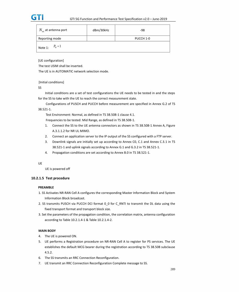
GTI 5G Function and Performance Test Specification v2.0 – June-2019
289
at antenna port dBm/30kHz -98
Reporting mode
PUCCH 1-0
Note 1:
[UE configuration]
The test USIM shall be inserted.
The UE is in AUTOMATIC network selection mode.
[Initial conditions]
SS
Initial conditions are a set of test configurations the UE needs to be tested in and the steps
for the SS to take with the UE to reach the correct measurement state.
Configurations of PUSCH and PUCCH before measurement are specified in Annex G.2 of TS
38.521-1.
Test Environment: Normal, as defined in TS 38.508-1 clause 4.1.
Frequencies to be tested: Mid Range, as defined in TS 38.508-1.
1. Connect the SS to the UE antenna connectors as shown in TS 38.508-1 Annex A, Figure
A.3.1.1.2 for NR UL MIMO.
2. Connect an application server to the IP output of the SS configured with a FTP server.
3. Downlink signals are initially set up according to Annex C0, C.1 and Annex C.3.1 in TS
38.521-1 and uplink signals according to Annex G.1 and G.3.2 in TS 38.521-1.
4. Propagation conditions are set according to Annex B.0 in TS 38.521-1.
UE
UE is powered off
10.2.1.5 Test procedure
PREAMBLE
1. SS Activates NR-RAN Cell A configures the corresponding Master Information Block and System
Information Block broadcast.
2. SS transmits PUSCH via PUCCH DCI format 0_0 for C_RNTI to transmit the DL data using the
fixed transport format and transport block size.
3. Set the parameters of the propagation condition, the correlation matrix, antenna configuration
according to Table 10.2.1.4-1 & Table 10.2.1.4-2.
MAIN BODY
4. The UE is powered ON.
5. UE performs a Registration procedure on NR-RAN Cell A to register for PS services. The UE
establishes the default MCG bearer during the registration according to TS 38.508 subclause
4.5.2.
6. The SS transmits an RRC Connection Reconfiguration.
7. UE transmit an RRC Connection Reconfiguration Complete message to SS.
ocN
1BP

GTI 5G Function and Performance Test Specification v2.0 – June-2019
290
8. Using the FTP client, begin FTP upload from the application server for [90] seconds and
record Throughput result.
9. Repeat step 10 for one more iteration.
10. Calculate the average throughput at the application layer on the uplink channel during the
file transfer over all iterations.
11. Switch Off UE, UE initiates a Detach procedure.
POSTAMBLE
12. Deactivate Cell.
Table 10.2.1.5-1: Message Sequence
Step Message Sequence Verdict
U-S Layer Message Specific Contents
1
RRC The SS Activates NR-RAN Cell A configures
the corresponding Master Information Block
and System Information Block broadcast
2 SS SS transmits PUSCH via PUCCH DCI format
0-0 for C_RNTI
3
SS Set the parameters of the bandwidth,
propagation condition, correlation matrix,
Special subframe configuration and antenna
configuration
4 Cell Power is set
5 UE Switch On UE AT Command
6 NAS
RRC
UE performs Registration procedure on
NR-RAN Cell A
PASS
7 RRC SS sends RRC Connection Reconfiguration
message
8 RRC The UE transmits RRC Connection
Reconfiguration Complete message
PASS
9 Using FTP Client begin FTP Upload PASS
10 Repeat Step 10
11 SS Calculate Average Throughput PASS
12 Switch Off UE AT Command
13 SS Deactivate Cell A
10.2.1.6 Expected Result
1. Calculate and record the average throughput.
2. Count and record the overall number of ACK and NACK/DTX on the PUSCH/PUCCH during the
test interval.
3. The average uplink throughput at the application layer shall meet or exceed the value in
following table.
Table 10.2.1.6-1: expected result

GTI 5G Function and Performance Test Specification v2.0 – June-2019
291
Test Point Expected UL Result [Mbit/s]
NR-1 FFS
10.2.2 UL Throughput under static channel, UL 256QAM, Single TX, HPUE
10.2.2.1 Test Purpose
To measure the UE application layer uplink performance while uploading TCP based data in
Conducted, Static Channel, SA Option2, 100 MHz BW, Full Resource Allocation, UL 256QAM, Single TX,
HPUE
10.2.2.2 Reference specification
3GPP TS 38.331, 3GPP TS 38.508, 3GPP TS 38.521-1
10.2.2.3 Applicability
This test applies to Type 2 UEs.
10.2.2.4 Test conditions
[SS configuration]
NR-RAN Cell A
Cell Id=01 TAC = 01
MCC = 460 MNC = 00
NR-ARFCN= f1
rootSequenceIndex = 0
UL Modulation / Coding = 27
RB Allocation UL= Full
RB Allocation DL = Full
simultaneousAckNackAndCQI = TRUE
enableUL256QAM = TRUE
CPConfig = UL: Normal CP/DL: Normal CP
subcarrierSpacing=30kHz
Dl/UL switch period=5ms
[Common conditions]
Common conditions include a set of test points the UE needs to be tested in and the common
test parameters for each transmission mode.
Table 10.2.2.4-1: Test Points Configuration
Test Point Propagation
Conditions
Correlation
Matrices
NR-1 Static N/A
Table 10.2.2.4-2: Test Parameters for Testing

GTI 5G Function and Performance Test Specification v2.0 – June-2019
292
Parameter Unit Value
Downlink power
allocation
dB -3
dB -3(Note 1)
at antenna port dBm/30kHz -98
Reporting mode
PUCCH 1-0
Note 1:
[UE configuration]
The test USIM shall be inserted.
The UE is in AUTOMATIC network selection mode.
[Initial conditions]
SS
Initial conditions are a set of test configurations the UE needs to be tested in and the steps
for the SS to take with the UE to reach the correct measurement state.
Configurations of PUSCH and PUCCH before measurement are specified in Annex G.2 of TS
38.521-1.
Test Environment: Normal, as defined in TS 38.508-1 clause 4.1.
Frequencies to be tested: Mid Range, as defined in TS 38.508-1.
1. Connect the SS to the UE antenna connectors as shown in TS 36.508-1 Annex A, Figure
A.3.1.1.1 for basic single cell.
2. Connect an application server to the IP output of the SS configured with a FTP server.
3. Downlink signals are initially set up according to Annex C0, C.1 and Annex C.3.1 in TS
38.521-1 and uplink signals according to Annex G.1 and G.3.2 in TS 38.521-1.
4. Propagation conditions are set according to Annex B.0 in TS 38.521-1.
UE
UE is powered off
10.2.2.5 Test procedure
PREAMBLE
1. SS Activates NR-RAN Cell A configures the corresponding Master Information Block and
System Information Block broadcast.
2. SS transmits PUSCH via PUCCH DCI format 0_0 for C_RNTI to transmit the UL data using the
fixed transport format and transport block size.
3. Set the parameters of the propagation condition, the correlation matrix, antenna
configuration according to Table 10.2.2.4-1 & Table 10.2.2.4-2.
MAIN BODY
4. The UE is powered ON.
5. UE performs a Registration procedure on NR-RAN Cell A to register for PS services. The UE
A
B
ocN
1BP

GTI 5G Function and Performance Test Specification v2.0 – June-2019
293
establishes the default MCG bearer during the registration according to TS 38.508 subclause
4.5.2.
6. The SS transmits an RRC Connection Reconfiguration.
7. UE transmit an RRC Connection Reconfiguration Complete message to SS.
8. Using the FTP client, begin FTP upload from the application server for [90] seconds and
record Throughput result.
9. Repeat step 10 for one more iteration.
10. Calculate the average throughput at the application layer on the uplink channel during the
file transfer over all iterations.
11. Switch Off UE, UE initiates a Detach procedure.
POSTAMBLE
12. Deactivate Cell.
Table 10.2.2.5-1: Message Sequence
Step Message Sequence Verdict
U-S Layer Message Specific Contents
1
RRC The SS Activates NR-RAN Cell A configures
the corresponding Master Information Block
and System Information Block broadcast
2 SS SS transmits PUSCH via PUCCH DCI format
0-0 for C_RNTI
3
SS Set the parameters of the bandwidth,
propagation condition, correlation matrix,
Special subframe configuration and antenna
configuration
4 Cell Power is set
5 UE Switch On UE AT Command
6 NAS
RRC
UE performs Registration procedure on
NR-RAN Cell A
PASS
7 RRC SS sends RRC Connection Reconfiguration
message
8 RRC The UE transmits RRC Connection
Reconfiguration Complete message
PASS
9 Using FTP Client begin FTP Upload PASS
10 Repeat Step 10
11 SS Calculate Average Throughput PASS
12 Switch Off UE AT Command
13 SS Deactivate Cell A
10.2.2.6 Expected Result
1. Calculate and record the average throughput.

GTI 5G Function and Performance Test Specification v2.0 – June-2019
294
2. Count and record the overall number of ACK and NACK/DTX on the PUSCH/PUCCH during the
test interval.
3. The average uplink throughput at the application layer shall meet or exceed the value in
following table.
Table 10.2.2.6-1: expected result
Test Point Expected UL Result [Mbit/s]
NR-1 FFS
10.2.3 UL Throughput under static channel, UL 256QAM, UL2*2 MIMO
10.2.3.1 Test Purpose
To measure the UE application layer uplink performance while uploading TCP based data in
Conducted, Static Channel, SA Option2, 100 MHz BW, Full Resource Allocation, UL 256QAM, UL2*2
MIMO
10.2.3.2 Reference specification
3GPP TS 38.331, 3GPP TS 38.508, 3GPP TS 38.521-1
10.2.3.3 Applicability
This test applies to Type 2 UEs.
10.2.3.4 Test conditions
[SS configuration]
NR-RAN Cell A
Cell Id=01 TAC = 01
MCC = FFS MNC = FFS
NR-ARFCN= f1
rootSequenceIndex = 0
UL Modulation / Coding = 27
RB Allocation UL= Full
RB Allocation DL = Full
simultaneousAckNackAndCQI = TRUE
enableUL256QAM = TRUE
CPConfig = UL: Normal CP/DL: Normal CP
subcarrierSpacing=30kHz
Dl/UL switch period=5ms
[Common conditions]
Common conditions include a set of test points the UE needs to be tested in and the common
test parameters for each transmission mode.

GTI 5G Function and Performance Test Specification v2.0 – June-2019
295
Table 10.2.3.4-1: Test Points Configuration
Test Point Propagation
Conditions
Correlation
Matrices
NR-1 Static N/A
Table 10.2.3.4-2: Test Parameters for Testing
Parameter Unit Value
Downlink power
allocation
dB -3
dB -3(Note 1)
at antenna port dBm/30kHz -98
Reporting mode
PUCCH 1-0
Note 1:
[UE configuration]
The test USIM shall be inserted.
The UE is in AUTOMATIC network selection mode.
[Initial conditions]
SS
Initial conditions are a set of test configurations the UE needs to be tested in and the steps
for the SS to take with the UE to reach the correct measurement state.
Configurations of PUSCH and PUCCH before measurement are specified in Annex G.2 of TS
38.521-1.
Test Environment: Normal, as defined in TS 38.508-1 clause 4.1.
Frequencies to be tested: Mid Range, as defined in TS 38.508-1.
1. Connect the SS to the UE antenna connectors as shown in TS 38.508-1 Annex A, Figure
A.3.1.1.2 for NR UL MIMO.
2. Connect an application server to the IP output of the SS configured with a FTP server.
3. Downlink signals are initially set up according to Annex C0, C.1 and Annex C.3.1 in TS
38.521-1 and uplink signals according to Annex G.1 and G.3.2 in TS 38.521-1.
4. Propagation conditions are set according to Annex B.0 in TS 38.521-1.
UE
UE is powered off
10.2.3.5 Test procedure
PREAMBLE
1. SS Activates NR-RAN Cell A configures the corresponding Master Information Block and
System Information Block broadcast.
2. SS transmits PUSCH via PUCCH DCI format 0_0 for C_RNTI to transmit the UL data using the
A
B
ocN
1BP
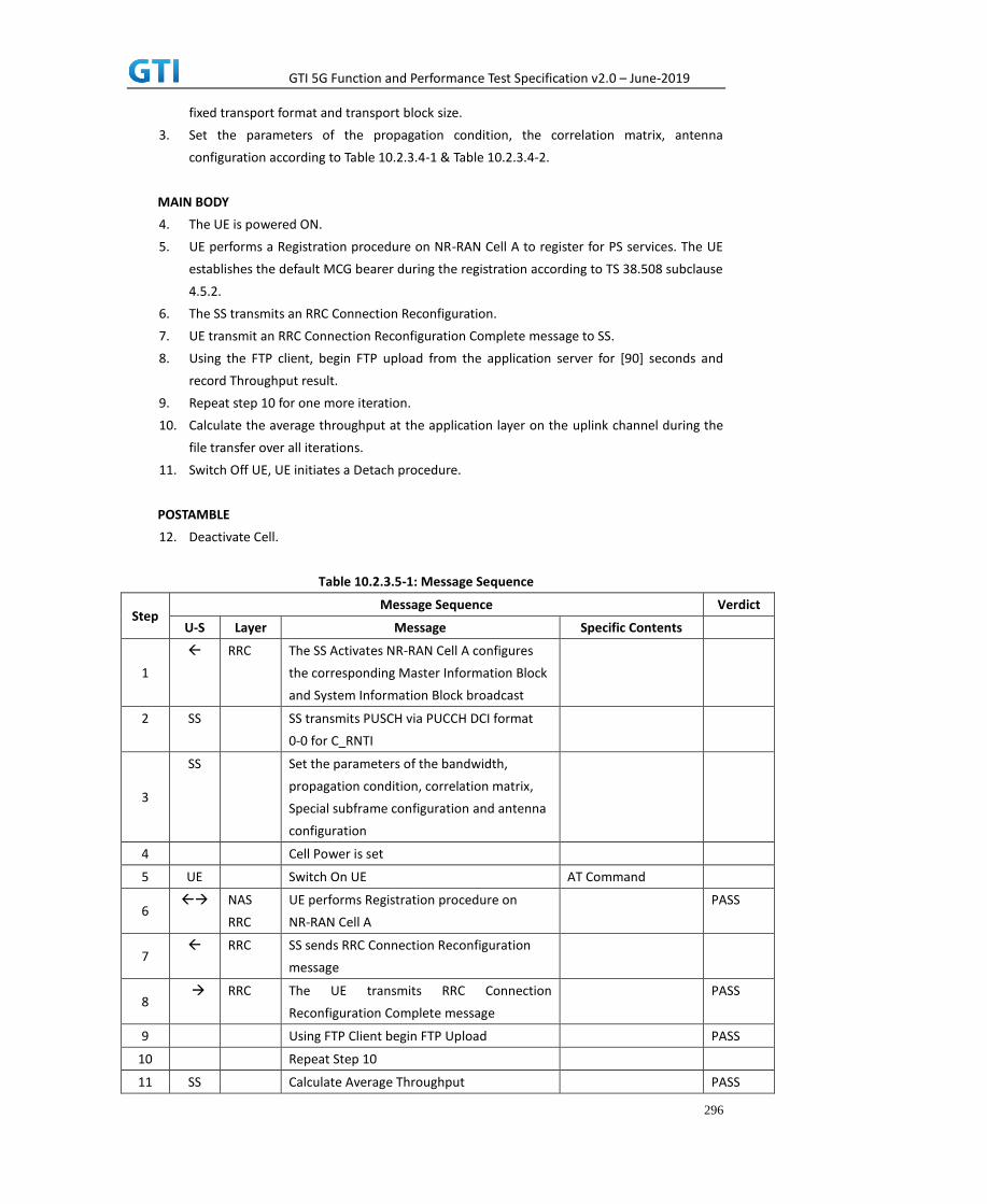
GTI 5G Function and Performance Test Specification v2.0 – June-2019
296
fixed transport format and transport block size.
3. Set the parameters of the propagation condition, the correlation matrix, antenna
configuration according to Table 10.2.3.4-1 & Table 10.2.3.4-2.
MAIN BODY
4. The UE is powered ON.
5. UE performs a Registration procedure on NR-RAN Cell A to register for PS services. The UE
establishes the default MCG bearer during the registration according to TS 38.508 subclause
4.5.2.
6. The SS transmits an RRC Connection Reconfiguration.
7. UE transmit an RRC Connection Reconfiguration Complete message to SS.
8. Using the FTP client, begin FTP upload from the application server for [90] seconds and
record Throughput result.
9. Repeat step 10 for one more iteration.
10. Calculate the average throughput at the application layer on the uplink channel during the
file transfer over all iterations.
11. Switch Off UE, UE initiates a Detach procedure.
POSTAMBLE
12. Deactivate Cell.
Table 10.2.3.5-1: Message Sequence
Step Message Sequence Verdict
U-S Layer Message Specific Contents
1
RRC The SS Activates NR-RAN Cell A configures
the corresponding Master Information Block
and System Information Block broadcast
2 SS SS transmits PUSCH via PUCCH DCI format
0-0 for C_RNTI
3
SS Set the parameters of the bandwidth,
propagation condition, correlation matrix,
Special subframe configuration and antenna
configuration
4 Cell Power is set
5 UE Switch On UE AT Command
6 NAS
RRC
UE performs Registration procedure on
NR-RAN Cell A
PASS
7 RRC SS sends RRC Connection Reconfiguration
message
8 RRC The UE transmits RRC Connection
Reconfiguration Complete message
PASS
9 Using FTP Client begin FTP Upload PASS
10 Repeat Step 10
11 SS Calculate Average Throughput PASS

GTI 5G Function and Performance Test Specification v2.0 – June-2019
297
12 Switch Off UE AT Command
13 SS Deactivate Cell A
10.2.3.6 Expected Result
1. Calculate and record the average throughput.
2. Count and record the overall number of ACK and NACK/DTX on the PUSCH/PUCCH during the
test interval.
3. The average downlink throughput at the application layer shall meet or exceed the value in
following table.
Table 10.2.3.6-1: expected result
Test Point Expected UL Result [Mbit/s]
NR-1 FFS
10.3 Bidirectional UDP Throughput
10.3.1 Bidirectional Throughput under static channel,256QAM, DL 4*4 and UL 2*2
MIMO
10.3.1.1 Test Purpose
To measure the UE application layer Bidirectional performance while downloading & uploading
simultaneously UDP based data in Conducted, Static Channel, SA Option2, 100 MHz BW, Full Resource
Allocation, 256QAM, DL 4*4 and UL 2*2 MIMO
10.3.1.2 Reference specification
3GPP TS 38.331, 3GPP TS 38.508, 3GPP TS 38.521-1
10.3.1.3 Applicability
This test applies to Type 2 UEs.
10.3.1.4 Test conditions
[SS configuration]
NR-RAN Cell A
Cell Id=01 TAC = 01
MCC = 460 MNC = 00
NR-ARFCN= f1
rootSequenceIndex = 0
DL Modulation / Coding = 27
UL Modulation / Coding = 27
RB Allocation UL= Full
RB Allocation DL = Full
simultaneousAckNackAndCQI = TRUE

GTI 5G Function and Performance Test Specification v2.0 – June-2019
298
enableDL4x4MIMO = TRUE
enableDL256QAM = TRUE
enableUL2x2MIMO = TRUE
enableUL64QAM = TRUE
CPConfig = UL: Normal CP/DL: Normal CP
subcarrierSpacing=30kHz
Dl/UL switch period=5ms
[Common conditions]
Common conditions include a set of test points the UE needs to be tested in and the common
test parameters for each transmission mode.
Table 10.3.1.4-1: Test Points Configuration
Test Point Propagation
Conditions
Correlation
Matrices
NR-1 Static N/A
Table 10.3.1.4-2: Test Parameters for Testing
Parameter Unit Value
Downlink power
allocation
dB -3
dB -3(Note 1)
at antenna port dBm/30kHz -98
Reporting mode
PUCCH 1-0
Note 1:
[UE configuration]
The test USIM shall be inserted.
The UE is in AUTOMATIC network selection mode.
[Initial conditions]
SS
Initial conditions are a set of test configurations the UE needs to be tested in and the steps for the
SS to take with the UE to reach the correct measurement state.
Configurations of PDSCH and PDCCH before measurement are specified in Annex C.2 of TS
Configurations of PUSCH and PUCCH before measurement are specified in Annex G.2 of TS
38.521-1.
38.521-1.
Test Environment: Normal, as defined in TS 38.508-1 clause 4.1.
Frequencies to be tested: Mid Range, as defined in TS 38.508-1.
A
B
ocN
1BP

GTI 5G Function and Performance Test Specification v2.0 – June-2019
299
1. Connect the SS to the UE antenna connectors as shown in TS 36.508-1 Annex A, Figure
A.3.2.1.5 for antenna configuration 4x4.
2. Connect an application server to the IP output of the SS configured with a FTP server.
3. Downlink signals are initially set up according to Annex C0, C.1 and Annex C.3.1 in TS
38.521-1 and uplink signals according to Annex G.1 and G.3.2 in TS 38.521-1.
4. Propagation conditions are set according to Annex B.0 in TS 38.521-1.
UE
UE is powered off
10.3.1.5 Test procedure
PREAMBLE
1. SS Activates NR-RAN Cell A configures the corresponding Master Information Block and
System Information Block broadcast.
2. SS transmits PDSCH via PDCCH DCI format 1_0 for C_RNTI to transmit the DL data using the
fixed transport format and transport block size.
3. Set the parameters of the propagation condition, the correlation matrix, antenna
configuration according to Table 10.3.1.4-1 & Table 10.3.1.4-2.
MAIN BODY
4. The UE is powered ON.
5. UE performs a Registration procedure on NR-RAN Cell A to register for PS services. The UE
establishes the default MCG bearer during the registration according to TS 38.508 subclause
4.5.2.
6. The SS transmits an RRC Connection Reconfiguration.
7. UE transmit an RRC Connection Reconfiguration Complete message to SS.
8. Using the FTP client, begin FTP download from the application server for [90] seconds and
record Throughput result.
9. Repeat step 10 for one more iteration.
10. Calculate the average throughput at the application layer on the downlink channel during
the file transfer over all iterations.
11. Switch Off UE, UE initiates a Detach procedure.
POSTAMBLE
12. Deactivate Cell.
Table 10.3.1.5-1: Message Sequence
Step Message Sequence Verdict
U-S Layer Message Specific Contents
1
RRC The SS Activates NR-RAN Cell A configures
the corresponding Master Information Block
and System Information Block broadcast
2 SS SS transmits PDSCH via PDCCH DCI format
1-0 for C_RNTI

GTI 5G Function and Performance Test Specification v2.0 – June-2019
300
3
SS Set the parameters of the bandwidth,
propagation condition, correlation matrix,
Special subframe configuration and antenna
configuration
4 Cell Power is set
5 UE Switch On UE AT Command
6
NAS
RRC
UE performs Registration procedure on
NR-RAN Cell A
PASS
7 RRC SS sends RRC Connection Reconfiguration
message
8 RRC The UE transmits RRC Connection
Reconfiguration Complete message
PASS
9 Using FTP Client begin FTP Download PASS
10 Repeat Step 10
11 SS Calculate Average Throughput PASS
12 Switch Off UE AT Command
13 SS Deactivate Cell A
10.3.1.6 Expected Result
1. Calculate and record the average throughput.
2. Count and record the overall number of ACK and NACK/DTX on the PUSCH/PUCCH during the
test interval.
3. The average downlink throughput at the application layer shall meet or exceed the value in
following table.
Table 10.3.1.6-1: expected result
Test Point Expected DL
Result [Mbit/s]
NR-1 FFS
10.3.2 Bidirectional Throughput under fading channel,256QAM, DL 4*4 and UL 2*2
MIMO
10.3.2.1 Test Purpose
To measure the UE application layer Bidirectional performance while downloading & uploading
simultaneously UDP based data in Conducted, Fading Channel, SA Option2, 100 MHz BW, Full
Resource Allocation, 256QAM, DL 4*4 and UL 2*2 MIMO
10.3.2.2 Reference specification
3GPP TS 38.331, 3GPP TS 38.508, 3GPP TS 38.521-1
10.3.2.3 Applicability

GTI 5G Function and Performance Test Specification v2.0 – June-2019
301
This test applies to Type 2 UEs.
10.3.2.4 Test conditions
[SS configuration]
NR-RAN Cell A
Cell Id=01 TAC = 01
MCC = 460 MNC = 00
NR-ARFCN= f1
rootSequenceIndex = 0
DL Modulation / Coding = 27
UL Modulation / Coding = 27
RB Allocation UL= Full
RB Allocation DL = Full
simultaneousAckNackAndCQI = TRUE
enableDL4x4MIMO = TRUE
enableDL256QAM = TRUE
enableUL2x2MIMO = TRUE
enableUL64QAM = TRUE
CPConfig = UL: Normal CP/DL: Normal CP
subcarrierSpacing=30kHz
Dl/UL switch period=5ms
[Common conditions]
Common conditions include a set of test points the UE needs to be tested in and the common
test parameters for each transmission mode.
Table 10.3.2.4-1: Test Points Configuration
Test Point Propagation
Conditions
Correlation
Matrices
NR-1 Fading Profile : FFS FFS
Table 10.3.2.4-2: Test Parameters for Testing
Parameter Unit Value
Downlink power
allocation
dB -3
dB -3(Note 1)
at antenna port dBm/30kHz -98
Reporting mode
PUCCH 1-0
Note 1:
[UE configuration]
A
B
ocN
1BP

GTI 5G Function and Performance Test Specification v2.0 – June-2019
302
The test USIM shall be inserted.
The UE is in AUTOMATIC network selection mode.
[Initial conditions]
SS
Initial conditions are a set of test configurations the UE needs to be tested in and the steps for the
SS to take with the UE to reach the correct measurement state.
Configurations of PDSCH and PDCCH before measurement are specified in Annex C.2 of TS
38.521-1.
Test Environment: Normal, as defined in TS 38.508-1 clause 4.1.
Frequencies to be tested: Mid Range, as defined in TS 38.508-1.
1. Connect the SS to the UE antenna connectors as shown in TS 36.508-1 Annex A, Figure A.3.2.1.5
for antenna configuration 4x4.
2. Connect an application server to the IP output of the SS configured with a FTP server.
3. Downlink signals are initially set up according to Annex C0, C.1 and Annex C.3.1 in TS 38.521-1
and uplink signals according to Annex G.1 and G.3.2 in TS 38.521-1.
4. Propagation conditions are set according to Annex B.0 in TS 38.521-1.
UE
UE is powered off
10.3.2.5 Test procedure
PREAMBLE
1. SS Activates NR-RAN Cell A configures the corresponding Master Information Block and
System Information Block broadcast.
2. SS transmits PDSCH via PDCCH DCI format 1_0 for C_RNTI to transmit the DL data using the
fixed transport format and transport block size.
3. Set the parameters of the propagation condition, the correlation matrix, antenna
configuration according to Table 10.3.2.4-1 & Table 10.3.2.4-2.
MAIN BODY
4. The UE is powered ON.
5. UE performs a Registration procedure on NR-RAN Cell A to register for PS services. The UE
establishes the default MCG bearer during the registration according to TS 38.508 subclause
4.5.2.
6. The SS transmits an RRC Connection Reconfiguration.
7. UE transmit an RRC Connection Reconfiguration Complete message to SS.
8. Using the FTP client, begin FTP download from the application server for [90] seconds and
record Throughput result.
9. Repeat step 10 for one more iteration.
10. Calculate the average throughput at the application layer on the downlink channel during
the file transfer over all iterations.
11. Switch Off UE, UE initiates a Detach procedure.

GTI 5G Function and Performance Test Specification v2.0 – June-2019
303
POSTAMBLE
12. Deactivate Cell.
Table 10.3.2.5-1: Message Sequence
Step Message Sequence Verdict
U-S Layer Message Specific Contents
1
RRC The SS Activates NR-RAN Cell A configures
the corresponding Master Information Block
and System Information Block broadcast
2 SS SS transmits PDSCH via PDCCH DCI format
1-0 for C_RNTI
3
SS Set the parameters of the bandwidth,
propagation condition, correlation matrix,
Special subframe configuration and antenna
configuration
4 Cell Power is set
5 UE Switch On UE AT Command
6 NAS
RRC
UE performs Registration procedure on
NR-RAN Cell A
PASS
7 RRC SS sends RRC Connection Reconfiguration
message
8 RRC The UE transmits RRC Connection Reconfiguration Complete message
PASS
9 Using FTP Client begin FTP Download PASS
10 Repeat Step 10
11 SS Calculate Average Throughput PASS
12 Switch Off UE AT Command
13 SS Deactivate Cell A
10.3.2.6 Expected Result
1. Calculate and record the average throughput.
2. Count and record the overall number of ACK and NACK/DTX on the PUSCH/PUCCH during the
test interval.
3. The average downlink throughput at the application layer shall meet or exceed the value in
following table.
Table 10.3.2.6-1: expected result
Test Point Expected DL Result [Mbit/s]
NR-1 FFS
10.4 Downlink TCP Throughput, NSA
10.4.1 DL Throughput under static channel, NSA

GTI 5G Function and Performance Test Specification v2.0 – June-2019
304
10.4.1.1 Test Purpose
To measure the UE application layer downlink performance while downloading TCP based data in
Conducted, Static Channel, NSA Option3, 100 MHz BW, Full Resource Allocation, 256QAM, DL NR
4*4 MIMO + LTE 2*2 MIMO, data transmission on MCG and SCG simultaneously
10.4.1.2 Reference specification
3GPP TS 36.331, 3GPP TS 36.508, 3GPP TS 36.521-1, 3GPP TS 38.331, 3GPP TS 38.508, 3GPP TS
38.521-1
10.4.1.3 Applicability
This test applies to Type 1 and Type 3 devices as described in clause 4.2.
10.4.1.4 Test conditions
[SS configuration]
E-UTRAN Cell A,
NR-RAN Cell B
E-UTRAN Cell A,
Cell Id=01 TAC = 01
MCC = 460 MNC = 00
EARFCN= f1
rootSequenceIndex = 0
DL Modulation / Coding = 27
RB Allocation UL= Full
RB Allocation DL = Full
simultaneousAckNackAndCQI = TRUE
enable256QAM = TRUE
CPConfig = UL: Normal CP/DL: Normal CP
NR-RAN Cell B,
Cell Id=02 TAC = 01
NR-ARFCN= f1
rootSequenceIndex = 0
DL Modulation / Coding = 27
RB Allocation UL= Full
RB Allocation DL = Full
simultaneousAckNackAndCQI = TRUE
enable4x4MIMO = TRUE
enable256QAM = TRUE
CPConfig = UL: Normal CP/DL: Normal CP
[Common conditions]
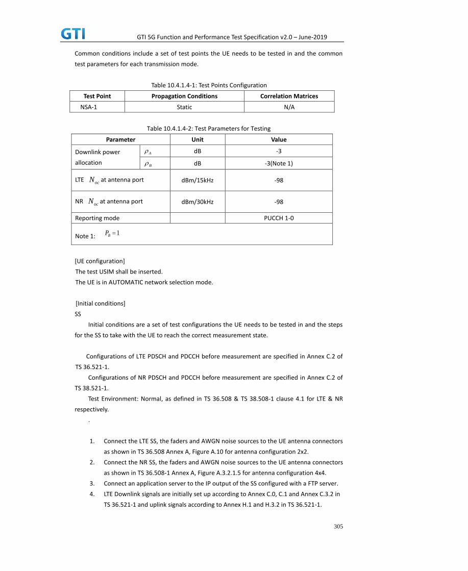
GTI 5G Function and Performance Test Specification v2.0 – June-2019
305
Common conditions include a set of test points the UE needs to be tested in and the common
test parameters for each transmission mode.
Table 10.4.1.4-1: Test Points Configuration
Test Point Propagation Conditions Correlation Matrices
NSA-1 Static N/A
Table 10.4.1.4-2: Test Parameters for Testing
Parameter Unit Value
Downlink power
allocation
dB -3
dB -3(Note 1)
LTE at antenna port dBm/15kHz -98
NR at antenna port
dBm/30kHz -98
Reporting mode
PUCCH 1-0
Note 1:
[UE configuration]
The test USIM shall be inserted.
The UE is in AUTOMATIC network selection mode.
[Initial conditions]
SS
Initial conditions are a set of test configurations the UE needs to be tested in and the steps
for the SS to take with the UE to reach the correct measurement state.
Configurations of LTE PDSCH and PDCCH before measurement are specified in Annex C.2 of
TS 36.521-1.
Configurations of NR PDSCH and PDCCH before measurement are specified in Annex C.2 of
TS 38.521-1.
Test Environment: Normal, as defined in TS 36.508 & TS 38.508-1 clause 4.1 for LTE & NR
respectively.
.
1. Connect the LTE SS, the faders and AWGN noise sources to the UE antenna connectors
as shown in TS 36.508 Annex A, Figure A.10 for antenna configuration 2x2.
2. Connect the NR SS, the faders and AWGN noise sources to the UE antenna connectors
as shown in TS 36.508-1 Annex A, Figure A.3.2.1.5 for antenna configuration 4x4.
3. Connect an application server to the IP output of the SS configured with a FTP server.
4. LTE Downlink signals are initially set up according to Annex C.0, C.1 and Annex C.3.2 in
TS 36.521-1 and uplink signals according to Annex H.1 and H.3.2 in TS 36.521-1.
A
B
ocN
ocN
1BP
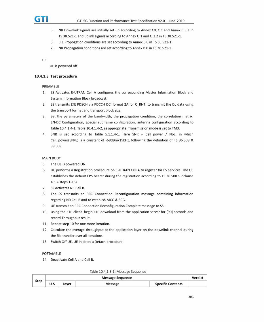
GTI 5G Function and Performance Test Specification v2.0 – June-2019
306
5. NR Downlink signals are initially set up according to Annex C0, C.1 and Annex C.3.1 in
TS 38.521-1 and uplink signals according to Annex G.1 and G.3.2 in TS 38.521-1.
6. LTE Propogation conditions are set according to Annex B.0 in TS 36.521-1.
7. NR Propagation conditions are set according to Annex B.0 in TS 38.521-1.
UE
UE is powered off
10.4.1.5 Test procedure
PREAMBLE
1. SS Activates E-UTRAN Cell A configures the corresponding Master Information Block and
System Information Block broadcast.
2. SS transmits LTE PDSCH via PDCCH DCI format 2A for C_RNTI to transmit the DL data using
the transport format and transport block size.
3. Set the parameters of the bandwidth, the propagation condition, the correlation matrix,
EN-DC Configuration, Special subframe configuration, antenna configuration according to
Table 10.4.1.4-1, Table 10.4.1.4-2, as appropriate. Transmission mode is set to TM3.
4. SNR is set according to Table 5.1.1.4-1. Here SNR = Cell_power / Noc, in which
Cell_power(EPRE) is a constant of -68dBm/15kHz, following the definition of TS 36.508 &
38.508.
MAIN BODY
5. The UE is powered ON.
6. UE performs a Registration procedure on E-UTRAN Cell A to register for PS services. The UE
establishes the default EPS bearer during the registration according to TS 36.508 subclause
4.5.2(steps 1-16).
7. SS Activates NR Cell B.
8. The SS transmits an RRC Connection Reconfiguration message containing information
regarding NR Cell B and to establish MCG & SCG.
9. UE transmit an RRC Connection Reconfiguration Complete message to SS.
10. Using the FTP client, begin FTP download from the application server for [90] seconds and
record Throughput result.
11. Repeat step 10 for one more iteration.
12. Calculate the average throughput at the application layer on the downlink channel during
the file transfer over all iterations.
13. Switch Off UE, UE initiates a Detach procedure.
POSTAMBLE
14. Deactivate Cell A and Cell B.
Table 10.4.1.5-1: Message Sequence
Step Message Sequence Verdict
U-S Layer Message Specific Contents

GTI 5G Function and Performance Test Specification v2.0 – June-2019
307
1
RRC The SS Activates E-UTRAN Cell A configures
the corresponding Master Information Block
and System Information Block broadcast
2 SS SS transmits PDSCH via PDCCH DCI format 2A
for C_RNTI
3
SS Set the parameters of the bandwidth,
propagation condition, correlation matrix,
EN-DC Configuration, Special subframe
configuration and antenna configuration
4 Cell Power is set
5 UE Switch On UE AT Command
6 NAS
RRC
UE performs Registration procedure on
E-UTRAN Cell A
PASS
7 The SS activates NR Cell B
8 RRC SS sends RRC Connection Reconfiguration
message
9 RRC The UE transmits RRC Connection
Reconfiguration Complete message
PASS
10 Using FTP Client begin FTP Download PASS
11 Repeat Step 10
12 SS Calculate Average Throughput PASS
13 Switch Off UE AT Command
14 SS Deactivate Cell A & Cell B
10.4.1.6 Expected Result
1. Calculate and record the average downlink TCP throughput
2. Calculate and record the average downlink throughput in MAC layer in SCG cell and MCG
cell respectively
3. Count and record the overall number of ACK and NACK/DTX on the PUSCH/PUCCH during
the test interval.
4. The average downlink throughput at the application layer shall meet or exceed the value in
following table.
Table 10.4.1.6-1: Expected Result for EN-DC FDD LTE Band + NR Band
Expected DL TCP Throughput Expected DL MAC
Throughput in MCG
Expected DL MAC
Throughput in SCG
[1.8 Gbps] [100 Mbps] [1.7 Gbps]
10.4.2 DL Throughput under fading channel, NSA
10.4.2.1 Test Purpose
To measure the UE application layer downlink performance while downloading TCP based data in
Conducted, fading Channel, NSA Option3, 100 MHz BW, Full Resource Allocation, dynamic
scheduling based on channel condition, data transmission on MCG and SCG simultaneously
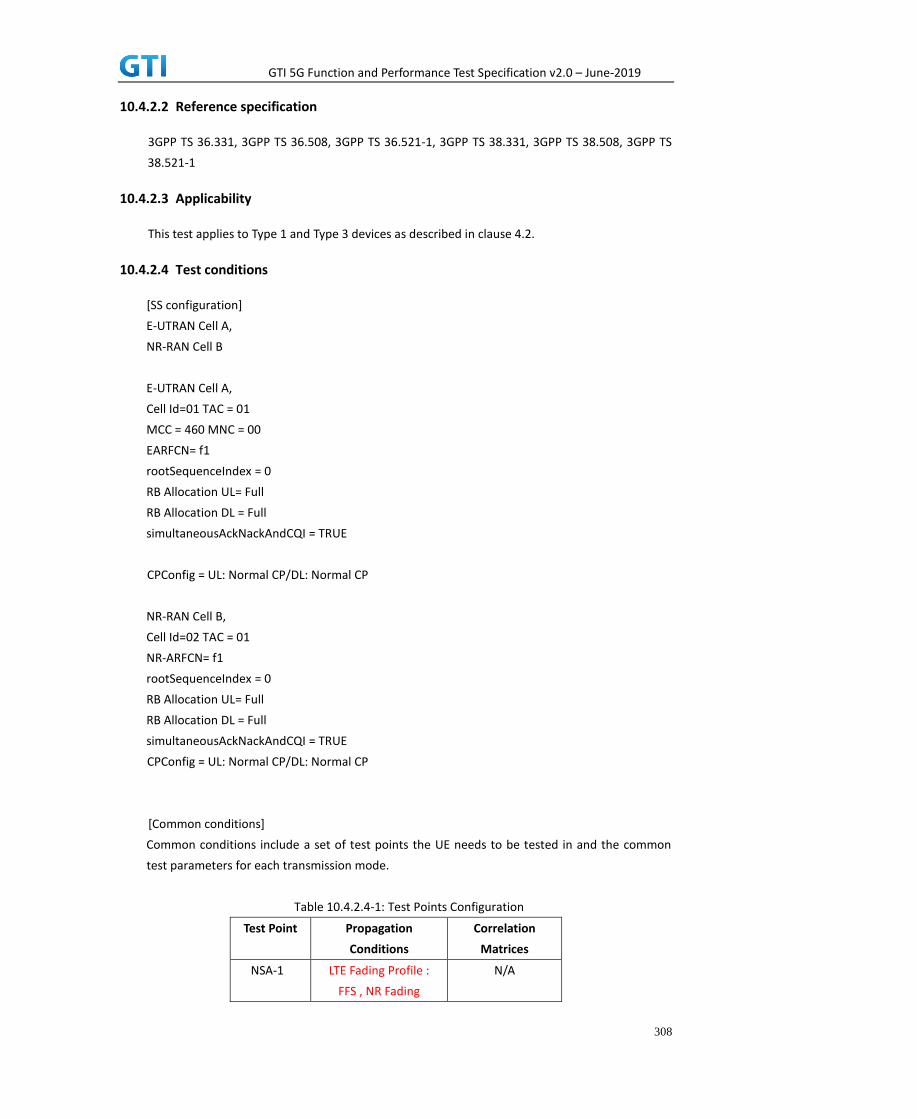
GTI 5G Function and Performance Test Specification v2.0 – June-2019
308
10.4.2.2 Reference specification
3GPP TS 36.331, 3GPP TS 36.508, 3GPP TS 36.521-1, 3GPP TS 38.331, 3GPP TS 38.508, 3GPP TS
38.521-1
10.4.2.3 Applicability
This test applies to Type 1 and Type 3 devices as described in clause 4.2.
10.4.2.4 Test conditions
[SS configuration]
E-UTRAN Cell A,
NR-RAN Cell B
E-UTRAN Cell A,
Cell Id=01 TAC = 01
MCC = 460 MNC = 00
EARFCN= f1
rootSequenceIndex = 0
RB Allocation UL= Full
RB Allocation DL = Full
simultaneousAckNackAndCQI = TRUE
CPConfig = UL: Normal CP/DL: Normal CP
NR-RAN Cell B,
Cell Id=02 TAC = 01
NR-ARFCN= f1
rootSequenceIndex = 0
RB Allocation UL= Full
RB Allocation DL = Full
simultaneousAckNackAndCQI = TRUE
CPConfig = UL: Normal CP/DL: Normal CP
[Common conditions]
Common conditions include a set of test points the UE needs to be tested in and the common
test parameters for each transmission mode.
Table 10.4.2.4-1: Test Points Configuration
Test Point Propagation
Conditions
Correlation
Matrices
NSA-1 LTE Fading Profile :
FFS , NR Fading
N/A

GTI 5G Function and Performance Test Specification v2.0 – June-2019
309
Profile : FFS
Table 10.4.2.4-2: Test Parameters for Testing
Parameter Unit Value
Downlink power
allocation
dB -3
dB -3(Note 1)
LTE at antenna port dBm/15kHz -98
NR at antenna port
dBm/30kHz -98
Reporting mode
PUCCH 1-0
Note 1:
[UE configuration]
The test USIM shall be inserted.
The UE is in AUTOMATIC network selection mode.
[Initial conditions]
SS
Initial conditions are a set of test configurations the UE needs to be tested in and the steps
for the SS to take with the UE to reach the correct measurement state.
Configurations of LTE PDSCH and PDCCH before measurement are specified in Annex C.2 of
TS 36.521-1.
Configurations of NR PDSCH and PDCCH before measurement are specified in Annex C.2 of
TS 38.521-1.
Test Environment: Normal, as defined in TS 36.508 & TS 38.508-1 clause 4.1 for LTE & NR
respectively.
Frequencies to be tested: Mid Range, as defined in TS 36.508 & TS 38.508-1 for LTE & NR
respectively.
1. Connect the LTE SS, the faders and AWGN noise sources to the UE antenna connectors
as shown in TS 36.508 Annex A, Figure A.10 for antenna configuration 2x2.
2. Connect the NR SS, the faders and AWGN noise sources to the UE antenna connectors
as shown in TS 38.508-1 Annex A, Figure A.3.2.1.5 for antenna configuration 4x4.
3. Connect an application server to the IP output of the SS configured with a FTP server.
4. LTE Downlink signals are initially set up according to Annex C.0, C.1 and Annex C.3.2 in
TS 36.521-1 and uplink signals according to Annex H.1 and H.3.2 in TS 36.521-1.
5. NR Downlink signals are initially set up according to Annex C0, C.1 and Annex C.3.1 in
TS 38.521-1 and uplink signals according to Annex G.1 and G.3.2 in TS 38.521-1.
6. LTE Propogation conditions are set according to Annex B.0 in TS 36.521-1.
7. NR Propagation conditions are set according to Annex B.0 in TS 38.521-1.
A
B
ocN
ocN
1BP

GTI 5G Function and Performance Test Specification v2.0 – June-2019
310
UE
UE is powered off
10.4.2.5 Test procedure
PREAMBLE
1. SS Activates E-UTRAN Cell A configures the corresponding Master Information Block and
System Information Block broadcast.
2. SS transmits LTE PDSCH via PDCCH DCI format 2A for C_RNTI to transmit the DL data using
the transport format and transport block size.
3. Set the parameters of the bandwidth, the propagation condition, the correlation matrix,
EN-DC Configuration, Special subframe configuration, antenna configuration according to
Table 10.4.2.4-1, Table 10.4.2.4-2, as appropriate. Transmission mode is set to TM3.
4. SNR is set according to Table 10.4.1.4-1. Here SNR = Cell_power / Noc, in which
Cell_power(EPRE) is a constant of -68dBm/15kHz, following the definition of TS 36.508 &
38.508.
MAIN BODY
5. The UE is powered ON.
6. UE performs a Registration procedure on E-UTRAN Cell A to register for PS services. The UE
establishes the default EPS bearer during the registration according to TS 36.508 subclause
4.5.2(steps 1-16).
7. SS Activates NR Cell B.
8. The SS transmits an RRC Connection Reconfiguration message containing information
regarding NR Cell B and to establish MCG & SCG.
9. UE transmit an RRC Connection Reconfiguration Complete message to SS.
10. Using the FTP client, begin FTP download from the application server for [90] seconds and
record Throughput result.
11. Repeat step 10 for one more iteration.
12. Calculate the average throughput at the application layer on the downlink channel during
the file transfer over all iterations.
13. Switch Off UE, UE initiates a Detach procedure.
POSTAMBLE
14. Deactivate Cell A and Cell B.
Table 10.4.2.5-1: Message Sequence
Step Message Sequence Verdict
U-S Layer Message Specific Contents
1
RRC The SS Activates E-UTRAN Cell A configures
the corresponding Master Information Block
and System Information Block broadcast
2 SS SS transmits PDSCH via PDCCH DCI format 2A
for C_RNTI

GTI 5G Function and Performance Test Specification v2.0 – June-2019
311
3
SS Set the parameters of the bandwidth,
propagation condition, correlation matrix,
EN-DC Configuration, Special subframe
configuration and antenna configuration
4 Cell Power is set
5 UE Switch On UE AT Command
6 NAS
RRC
UE performs Registration procedure on
E-UTRAN Cell A
PASS
7 The SS activates NR Cell B
8 RRC SS sends RRC Connection Reconfiguration
message
9 RRC The UE transmits RRC Connection
Reconfiguration Complete message
PASS
10 Using FTP Client begin FTP Download PASS
11 Repeat Step 10
12 SS Calculate Average Throughput PASS
13 Switch Off UE AT Command
14 SS Deactivate Cell A & Cell B
10.4.2.6 Expected Result
1. Calculate and record the average downlink TCP throughput.
2. Calculate and record the average downlink throughput in MAC layer in SCG cell and MCG
cell respectively
3. Count and record the overall number of ACK and NACK/DTX on the PUSCH/PUCCH during
the test interval.
4. The average downlink throughput at the application layer shall meet or exceed the value in
following table.
Table 10.4.2.6-1: Expected Result for EN-DC FDD LTE Band + NR Band
Expected DL TCP Throughput Expected DL MAC
Throughput in MCG
Expected DL MAC
Throughput in SCG
FFS FFS FFS
10.4.3 DL Throughput under static channel on SCG, DL 256QAM, NSA
10.4.3.1 Test Purpose
To measure the UE application layer downlink performance while downloading TCP based data in
Conducted, Static Channel, NSA Option3x, 100 MHz BW, Full Resource Allocation, 256QAM, DL
NR 4*4 MIMO, data transmission on SCG
10.4.3.2 Reference specification
3GPP TS 36.331, 3GPP TS 36.508, 3GPP TS 36.521-1, 3GPP TS 38.331, 3GPP TS 38.508, 3GPP TS
38.521-1

GTI 5G Function and Performance Test Specification v2.0 – June-2019
312
10.4.3.3 Applicability
This test applies to Type 1 and Type 3 devices as described in clause 4.2.
10.4.3.4 Test conditions
[SS configuration]
E-UTRAN Cell A,
NR-RAN Cell B
E-UTRAN Cell A,
Cell Id=01 TAC = 01
MCC = 460 MNC = 00
EARFCN= f1
rootSequenceIndex = 0
DL Modulation / Coding = 27
RB Allocation UL= Full
RB Allocation DL = Full
simultaneousAckNackAndCQI = TRUE
enable256QAM = TRUE
CPConfig = UL: Normal CP/DL: Normal CP
NR-RAN Cell B,
Cell Id=02 TAC = 01
NR-ARFCN= f1
rootSequenceIndex = 0
DL Modulation / Coding = 27
RB Allocation UL= Full
RB Allocation DL = Full
simultaneousAckNackAndCQI = TRUE
enable4x4MIMO = TRUE
enable256QAM = TRUE
CPConfig = UL: Normal CP/DL: Normal CP
[Common conditions]
Common conditions include a set of test points the UE needs to be tested in and the common
test parameters for each transmission mode.
Table 10.4.3.4-1: Test Points Configuration
Test Point Propagation Conditions Correlation Matrices
NSA-1 Static N/A
Table 10.4.3.4-2: Test Parameters for Testing

GTI 5G Function and Performance Test Specification v2.0 – June-2019
313
Parameter Unit Value
Downlink power
allocation
dB -3
dB -3(Note 1)
LTE at antenna port dBm/15kHz -98
NR at antenna port
dBm/30kHz -98
Reporting mode
PUCCH 1-0
Note 1:
[UE configuration]
The test USIM shall be inserted.
The UE is in AUTOMATIC network selection mode.
[Initial conditions]
SS
Initial conditions are a set of test configurations the UE needs to be tested in and the steps
for the SS to take with the UE to reach the correct measurement state.
Configurations of LTE PDSCH and PDCCH before measurement are specified in Annex C.2 of
TS 36.521-1.
Configurations of NR PDSCH and PDCCH before measurement are specified in Annex C.2 of
TS 38.521-1.
Test Environment: Normal, as defined in TS 36.508 & TS 38.508-1 clause 4.1 for LTE & NR
respectively.
.
1. Connect the LTE SS, the faders and AWGN noise sources to the UE antenna connectors
as shown in TS 36.508 Annex A, Figure A.10 for antenna configuration 2x2.
2. Connect the NR SS, the faders and AWGN noise sources to the UE antenna connectors
as shown in TS 36.508-1 Annex A, Figure A.3.2.1.5 for antenna configuration 4x4.
3. Connect an application server to the IP output of the SS configured with a FTP server.
4. LTE Downlink signals are initially set up according to Annex C.0, C.1 and Annex C.3.2 in
TS 36.521-1 and uplink signals according to Annex H.1 and H.3.2 in TS 36.521-1.
5. NR Downlink signals are initially set up according to Annex C0, C.1 and Annex C.3.1 in
TS 38.521-1 and uplink signals according to Annex G.1 and G.3.2 in TS 38.521-1.
6. LTE Propogation conditions are set according to Annex B.0 in TS 36.521-1.
7. NR Propagation conditions are set according to Annex B.0 in TS 38.521-1.
UE
UE is powered off
10.4.3.5 Test procedure
A
B
ocN
ocN
1BP
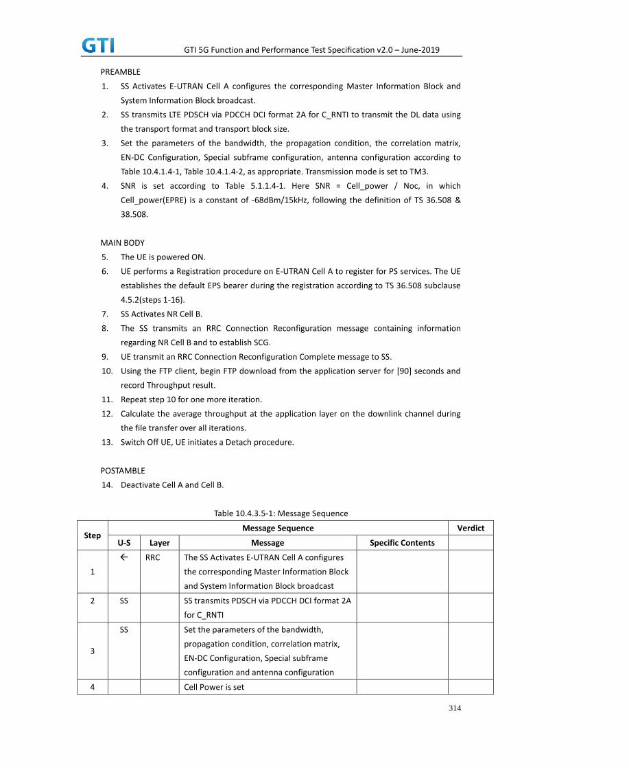
GTI 5G Function and Performance Test Specification v2.0 – June-2019
314
PREAMBLE
1. SS Activates E-UTRAN Cell A configures the corresponding Master Information Block and
System Information Block broadcast.
2. SS transmits LTE PDSCH via PDCCH DCI format 2A for C_RNTI to transmit the DL data using
the transport format and transport block size.
3. Set the parameters of the bandwidth, the propagation condition, the correlation matrix,
EN-DC Configuration, Special subframe configuration, antenna configuration according to
Table 10.4.1.4-1, Table 10.4.1.4-2, as appropriate. Transmission mode is set to TM3.
4. SNR is set according to Table 5.1.1.4-1. Here SNR = Cell_power / Noc, in which
Cell_power(EPRE) is a constant of -68dBm/15kHz, following the definition of TS 36.508 &
38.508.
MAIN BODY
5. The UE is powered ON.
6. UE performs a Registration procedure on E-UTRAN Cell A to register for PS services. The UE
establishes the default EPS bearer during the registration according to TS 36.508 subclause
4.5.2(steps 1-16).
7. SS Activates NR Cell B.
8. The SS transmits an RRC Connection Reconfiguration message containing information
regarding NR Cell B and to establish SCG.
9. UE transmit an RRC Connection Reconfiguration Complete message to SS.
10. Using the FTP client, begin FTP download from the application server for [90] seconds and
record Throughput result.
11. Repeat step 10 for one more iteration.
12. Calculate the average throughput at the application layer on the downlink channel during
the file transfer over all iterations.
13. Switch Off UE, UE initiates a Detach procedure.
POSTAMBLE
14. Deactivate Cell A and Cell B.
Table 10.4.3.5-1: Message Sequence
Step Message Sequence Verdict
U-S Layer Message Specific Contents
1
RRC The SS Activates E-UTRAN Cell A configures
the corresponding Master Information Block
and System Information Block broadcast
2 SS SS transmits PDSCH via PDCCH DCI format 2A
for C_RNTI
3
SS Set the parameters of the bandwidth,
propagation condition, correlation matrix,
EN-DC Configuration, Special subframe
configuration and antenna configuration
4 Cell Power is set

GTI 5G Function and Performance Test Specification v2.0 – June-2019
315
5 UE Switch On UE AT Command
6 NAS
RRC
UE performs Registration procedure on
E-UTRAN Cell A
PASS
7 The SS activates NR Cell B
8 RRC SS sends RRC Connection Reconfiguration
message
9 RRC The UE transmits RRC Connection
Reconfiguration Complete message
PASS
10 Using FTP Client begin FTP Download PASS
11 Repeat Step 10
12 SS Calculate Average Throughput PASS
13 Switch Off UE AT Command
14 SS Deactivate Cell A & Cell B
10.4.3.6 Expected Result
1. Calculate and record the average downlink TCP throughput
2. Calculate and record the average downlink throughput in MAC layer in SCG cell
3. Count and record the overall number of ACK and NACK/DTX on the PUSCH/PUCCH during
the test interval.
4. The average downlink throughput at the application layer shall meet or exceed the value in
following table.
Table 10.4.3.6-1: Expected Result for EN-DC FDD LTE Band + NR Band
Expected DL TCP Throughput Expected DL MAC Throughput in SCG
[1.7Gbps] [1.7Gbps]
10.4.4 DL Throughput under fading channel on SCG, NSA
10.4.4.1 Test Purpose
To measure the UE application layer downlink performance while downloading TCP based data in
Conducted, fading Channel, NSA Option3x, 100 MHz BW, Full Resource Allocation, dynamic
scheduling based on channel condition, data transmission on SCG
10.4.4.2 Reference specification
3GPP TS 36.331, 3GPP TS 36.508, 3GPP TS 36.521-1, 3GPP TS 38.331, 3GPP TS 38.508, 3GPP TS
38.521-1
10.4.4.3 Applicability
This test applies to Type 1 and Type 3 devices as described in clause 4.2.
10.4.4.4 Test conditions
[SS configuration]

GTI 5G Function and Performance Test Specification v2.0 – June-2019
316
E-UTRAN Cell A,
NR-RAN Cell B
E-UTRAN Cell A,
Cell Id=01 TAC = 01
MCC = 460 MNC = 00
EARFCN= f1
rootSequenceIndex = 0
RB Allocation UL= Full
RB Allocation DL = Full
simultaneousAckNackAndCQI = TRUE
CPConfig = UL: Normal CP/DL: Normal CP
NR-RAN Cell B,
Cell Id=02 TAC = 01
NR-ARFCN= f1
rootSequenceIndex = 0
RB Allocation UL= Full
RB Allocation DL = Full
simultaneousAckNackAndCQI = TRUE
CPConfig = UL: Normal CP/DL: Normal CP
[Common conditions]
Common conditions include a set of test points the UE needs to be tested in and the common
test parameters for each transmission mode.
Table 10.4.4.4-1: Test Points Configuration
Test Point Propagation
Conditions
Correlation
Matrices
NSA-1 LTE Fading Profile :
FFS , NR Fading
Profile : FFS
N/A
Table 10.4.4.4-2: Test Parameters for Testing
Parameter Unit Value
Downlink power
allocation
dB -3
dB -3(Note 1)
A
B

GTI 5G Function and Performance Test Specification v2.0 – June-2019
317
LTE at antenna port dBm/15kHz -98
NR at antenna port
dBm/30kHz -98
Reporting mode
PUCCH 1-0
Note 1:
[UE configuration]
The test USIM shall be inserted.
The UE is in AUTOMATIC network selection mode.
[Initial conditions]
SS
Initial conditions are a set of test configurations the UE needs to be tested in and the steps
for the SS to take with the UE to reach the correct measurement state.
Configurations of LTE PDSCH and PDCCH before measurement are specified in Annex C.2 of
TS 36.521-1.
Configurations of NR PDSCH and PDCCH before measurement are specified in Annex C.2 of
TS 38.521-1.
Test Environment: Normal, as defined in TS 36.508 & TS 38.508-1 clause 4.1 for LTE & NR
respectively.
1. Connect the LTE SS, the faders and AWGN noise sources to the UE antenna connectors
as shown in TS 36.508 Annex A, Figure A.10 for antenna configuration 2x2.
2. Connect the NR SS, the faders and AWGN noise sources to the UE antenna connectors
as shown in TS 38.508-1 Annex A, Figure A.3.2.1.5 for antenna configuration 4x4.
3. Connect an application server to the IP output of the SS configured with a FTP server.
4. LTE Downlink signals are initially set up according to Annex C.0, C.1 and Annex C.3.2 in
TS 36.521-1 and uplink signals according to Annex H.1 and H.3.2 in TS 36.521-1.
5. NR Downlink signals are initially set up according to Annex C0, C.1 and Annex C.3.1 in
TS 38.521-1 and uplink signals according to Annex G.1 and G.3.2 in TS 38.521-1.
6. LTE Propogation conditions are set according to Annex B.0 in TS 36.521-1.
7. NR Propagation conditions are set according to Annex B.0 in TS 38.521-1.
UE
UE is powered off
10.4.4.5 Test procedure
PREAMBLE
1. SS Activates E-UTRAN Cell A configures the corresponding Master Information Block and
System Information Block broadcast.
ocN
ocN
1BP

GTI 5G Function and Performance Test Specification v2.0 – June-2019
318
2. SS transmits LTE PDSCH via PDCCH DCI format 2A for C_RNTI to transmit the DL data using
the transport format and transport block size.
3. Set the parameters of the bandwidth, the propagation condition, the correlation matrix,
EN-DC Configuration, Special subframe configuration, antenna configuration according to
Table 10.4.2.4-1, Table 10.4.2.4-2, as appropriate. Transmission mode is set to TM3.
4. SNR is set according to Table 10.4.1.4-1. Here SNR = Cell_power / Noc, in which
Cell_power(EPRE) is a constant of -68dBm/15kHz, following the definition of TS 36.508 &
38.508.
MAIN BODY
5. The UE is powered ON.
6. UE performs a Registration procedure on E-UTRAN Cell A to register for PS services. The UE
establishes the default EPS bearer during the registration according to TS 36.508 sub clause
4.5.2(steps 1-16).
7. SS Activates NR Cell B.
8. The SS transmits an RRC Connection Reconfiguration message containing information
regarding NR Cell B and to establish SCG.
9. UE transmit an RRC Connection Reconfiguration Complete message to SS.
10. Using the FTP client, begin FTP download from the application server for [90] seconds and
record Throughput result.
11. Repeat step 10 for one more iteration.
12. Calculate the average throughput at the application layer on the downlink channel during
the file transfer over all iterations.
13. Switch Off UE, UE initiates a Detach procedure.
POSTAMBLE
14. Deactivate Cell A and Cell B.
Table 10.4.4.5-1: Message Sequence
Step Message Sequence Verdict
U-S Layer Message Specific Contents
1
RRC The SS Activates E-UTRAN Cell A configures
the corresponding Master Information Block
and System Information Block broadcast
2 SS SS transmits PDSCH via PDCCH DCI format 2A
for C_RNTI
3
SS Set the parameters of the bandwidth,
propagation condition, correlation matrix,
EN-DC Configuration, Special subframe
configuration and antenna configuration
4 Cell Power is set
5 UE Switch On UE AT Command
6 NAS
RRC
UE performs Registration procedure on
E-UTRAN Cell A
PASS
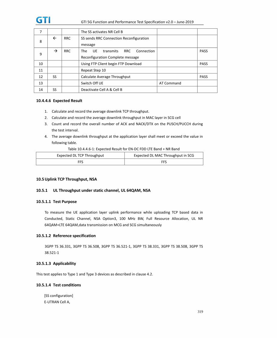
GTI 5G Function and Performance Test Specification v2.0 – June-2019
319
7 The SS activates NR Cell B
8 RRC SS sends RRC Connection Reconfiguration
message
9 RRC The UE transmits RRC Connection
Reconfiguration Complete message
PASS
10 Using FTP Client begin FTP Download PASS
11 Repeat Step 10
12 SS Calculate Average Throughput PASS
13 Switch Off UE AT Command
14 SS Deactivate Cell A & Cell B
10.4.4.6 Expected Result
1. Calculate and record the average downlink TCP throughput.
2. Calculate and record the average downlink throughput in MAC layer in SCG cell
3. Count and record the overall number of ACK and NACK/DTX on the PUSCH/PUCCH during
the test interval.
4. The average downlink throughput at the application layer shall meet or exceed the value in
following table.
Table 10.4.4.6-1: Expected Result for EN-DC FDD LTE Band + NR Band
Expected DL TCP Throughput Expected DL MAC Throughput in SCG
FFS FFS
10.5 Uplink TCP Throughput, NSA
10.5.1 UL Throughput under static channel, UL 64QAM, NSA
10.5.1.1 Test Purpose
To measure the UE application layer uplink performance while uploading TCP based data in
Conducted, Static Channel, NSA Option3, 100 MHz BW, Full Resource Allocation, UL NR
64QAM+LTE 64QAM,data transmission on MCG and SCG simultaneously
10.5.1.2 Reference specification
3GPP TS 36.331, 3GPP TS 36.508, 3GPP TS 36.521-1, 3GPP TS 38.331, 3GPP TS 38.508, 3GPP TS
38.521-1
10.5.1.3 Applicability
This test applies to Type 1 and Type 3 devices as described in clause 4.2.
10.5.1.4 Test conditions
[SS configuration]
E-UTRAN Cell A,

GTI 5G Function and Performance Test Specification v2.0 – June-2019
320
NR-RAN Cell B
E-UTRAN Cell A,
Cell Id=01 TAC = 01
MCC = 460 MNC = 00
EARFCN= f1
rootSequenceIndex = 0
UL Modulation / Coding = 28
RB Allocation UL= Full
RB Allocation DL = Full
simultaneousAckNackAndCQI = TRUE
enableUl64QAM = TRUE
CPConfig = UL: Normal CP/DL: Normal CP
NR-RAN Cell B,
Cell Id=02 TAC = 01
NR-ARFCN= f1
rootSequenceIndex = 0
UL Modulation / Coding = 28
RB Allocation UL= Full
RB Allocation DL = Full
simultaneousAckNackAndCQI = TRUE
enableUl64QAM = TRUE
CPConfig = UL: Normal CP/DL: Normal CP
[Common conditions]
Common conditions include a set of test points the UE needs to be tested in and the common
test parameters for each transmission mode.
Table 10.5.1.4-1: Test Points Configuration
Test Point Propagation Conditions Correlation Matrices
NR-1 Static N/A
Table 10.5.1.4-2: Test Parameters for Testing
Parameter Unit Value
Downlink power
allocation
dB -3
dB -3(Note 1)
A
B

GTI 5G Function and Performance Test Specification v2.0 – June-2019
321
LTE at antenna port dBm/15kHz -98
NR at antenna port
dBm/30kHz -98
Reporting mode
PUCCH 1-0
Note 1:
[UE configuration]
The test USIM shall be inserted.
The UE is in AUTOMATIC network selection mode.
[Initial conditions]
SS
Initial conditions are a set of test configurations the UE needs to be tested in and the steps
for the SS to take with the UE to reach the correct measurement state.
Configurations of LTE PUSCH and PUCCH before measurement are specified in Annex H.2 of
TS 36.521-1.
Configurations of NR PUSCH and PUCCH before measurement are specified in Annex G.2 of
TS 38.521-1.
Test Environment: Normal, as defined in TS 36.508 & TS 38.508-1 clause 4.1 for LTE & NR
respectively.
1. Connect the SS to the UE antenna connectors as shown in TS 38.508-1 Annex A, Figure
A.3.1.1.1.
2. Connect an application server to the IP output of the SS configured with a FTP server.
3. LTE Downlink signals are initially set up according to Annex C.0, C.1 and Annex C.3.2 in
TS 36.521-1 and uplink signals according to Annex H.1 and H.3.2 in TS 36.521-1.
4. NR Downlink signals are initially set up according to Annex C0, C.1 and Annex C.3.1 in
TS 38.521-1 and uplink signals according to Annex G.1 and G.3.2 in TS 38.521-1.
5. LTE Propogation conditions are set according to Annex B.0 in TS 36.521-1.
6. NR Propagation conditions are set according to Annex B.0 in TS 38.521-1.
UE
UE is powered off
10.5.1.5 Test procedure
PREAMBLE
1. SS Activates E-UTRAN Cell A configures the corresponding Master Information Block and
System Information Block broadcast.
2. SS transmits LTE PUSCH via PUCCH DCI format 0 for C_RNTI to transmit the UL data using
the transport format and transport block size. SS transmits PUSCH via PUCCH DCI format
ocN
ocN
1BP

GTI 5G Function and Performance Test Specification v2.0 – June-2019
322
0_0 for C_RNTI to transmit the UL data using the fixed transport format and transport block
size.
3. Set the parameters of the bandwidth, the propagation condition, the correlation matrix,
EN-DC Configuration, Special subframe configuration, antenna configuration according to
Table 10.5.1.4-1, Table 10.5.1.4-2, as appropriate. Transmission mode is set to TM3.
4. SNR is set according to Table 10.5.1.4-1. Here SNR = Cell_power / Noc, in which
Cell_power(EPRE) is a constant of -68dBm/15kHz, following the definition of TS 36.508 &
38.508.
MAIN BODY
5. The UE is powered ON.
6. UE performs a Registration procedure on E-UTRAN Cell A to register for PS services. The UE
establishes the default EPS bearer during the registration according to TS 36.508 subclause
4.5.2(steps 1-16).
7. SS Activates NR Cell B.
8. The SS transmits an RRC Connection Reconfiguration message containing information
regarding NR Cell B and to establish MCG & SCG.
9. UE transmit an RRC Connection Reconfiguration Complete message to SS.
10. Using the FTP client, begin FTP upload from the application server for [90] seconds and
record Throughput result.
11. Repeat step 10 for one more iteration.
12. Calculate the average throughput at the application layer on the uplink channel during the
file transfer over all iterations.
13. Switch Off UE, UE initiates a Detach procedure.
POSTAMBLE
14. Deactivate Cell A and Cell B.
Table 10.5.1.5-1: Message Sequence
Step Message Sequence Verdict
U-S Layer Message Specific Contents
1
RRC The SS Activates E-UTRAN Cell A configures
the corresponding Master Information Block
and System Information Block broadcast
2 SS SS transmits LTE PUSCH via PUCCH DCI
format 0 for C_RNTI to transmit the UL data
using the transport format and transport
block size. SS transmits PUSCH via PUCCH
DCI format 0_0_for C_RNTI to transmit the
DL data using the fixed transport format and
transport block size.

GTI 5G Function and Performance Test Specification v2.0 – June-2019
323
3
SS Set the parameters of the bandwidth,
propagation condition, correlation matrix,
EN-DC Configuration, Special subframe
configuration and antenna configuration
4 Cell Power is set
5 UE Switch On UE AT Command
6 NAS
RRC
UE performs Registration procedure on
E-UTRAN Cell A
PASS
7 The SS activates Cell B
8 RRC SS sends RRC Connection Reconfiguration
message
9 RRC The UE transmits RRC Connection
Reconfiguration Complete message
PASS
10 Using FTP Client begin FTP Upload PASS
11 Repeat Step 10
12 SS Calculate Average Throughput PASS
13 Switch Off UE AT Command
14 SS Deactivate Cell A
10.5.1.6 Expected Result
1. Calculate and record the average uplink TCP throughput.
2. Calculate and record the average uplink throughput in MAC layer in SCG cell and MCG cell
respectively
3. Count and record the overall number of ACK and NACK/DTX on the PUSCH/PUCCH during
the test interval.
4. The average uplink throughput at the application layer shall meet or exceed the value in
following table.
Table 10.5.1.6-1: Expected Result for EN-DC FDD LTE Band + NR Band
Expected UL TCP Throughput Expected UL MAC
Throughput in MCG
Expected UL MAC
Throughput in SCG
[130 Mbps] [37 Mbps] [ 95 Mbps]
10.5.2 UL Throughput under static channel, UL 256QAM, NSA
10.5.2.1 Test Purpose
To measure the UE application layer uplink performance while uploading TCP based data in
Conducted, Static Channel, NSA Option3, 100 MHz BW, Full Resource Allocation, UL NR
256QAM+LTE 64QAM,data transmission on MCG and SCG simultaneously
10.5.2.2 Reference specification
3GPP TS 36.331, 3GPP TS 36.508, 3GPP TS 36.521-1, 3GPP TS 38.331, 3GPP TS 38.508, 3GPP TS
38.521-1

GTI 5G Function and Performance Test Specification v2.0 – June-2019
324
10.5.2.3 Applicability
This test applies to Type 1 and Type 3 devices as described in clause 4.2.
10.5.2.4 Test conditions
[SS configuration]
E-UTRAN Cell A,
NR-RAN Cell B
E-UTRAN Cell A,
Cell Id=01 TAC = 01
MCC = 460 MNC = 00
EARFCN= f1
rootSequenceIndex = 0
UL Modulation / Coding = 28
RB Allocation UL= Full
RB Allocation DL = Full
simultaneousAckNackAndCQI = TRUE
enableUl64QAM = TRUE
CPConfig = UL: Normal CP/DL: Normal CP
NR-RAN Cell B,
Cell Id=02 TAC = 01
NR-ARFCN= f1
rootSequenceIndex = 0
UL Modulation / Coding = 27
RB Allocation UL= Full
RB Allocation DL = Full
simultaneousAckNackAndCQI = TRUE
enableUl256QAM = TRUE
CPConfig = UL: Normal CP/DL: Normal CP
[Common conditions]
Common conditions include a set of test points the UE needs to be tested in and the common
test parameters for each transmission mode.
Table 10.5.2.4-1: Test Points Configuration
Test Point Propagation
Conditions
Correlation
Matrices
NR-1 Static N/A
Table 10.5.2.4-2: Test Parameters for Testing

GTI 5G Function and Performance Test Specification v2.0 – June-2019
325
Parameter Unit Value
Downlink power
allocation
dB -3
dB -3(Note 1)
LTE at antenna port dBm/15kHz -98
LTE at antenna port
dBm/30kHz -98
Reporting mode
PUCCH 1-0
Note 1:
[UE configuration]
The test USIM shall be inserted.
The UE is in AUTOMATIC network selection mode.
[Initial conditions]
SS
Initial conditions are a set of test configurations the UE needs to be tested in and the steps
for the SS to take with the UE to reach the correct measurement state.
Configurations of LTE PUSCH and PUCCH before measurement are specified in Annex H.2 of
TS 36.521-1.
Configurations of NR PUSCH and PUCCH before measurement are specified in Annex G.2 of
TS 38.521-1.
Test Environment: Normal, as defined in TS 36.508 & TS 38.508-1 clause 4.1 for LTE & NR
respectively.
1. Connect the SS to the UE antenna connectors as shown in TS 38.508-1 Annex A, Figure
A.3.1.1.1.
2. Connect an application server to the IP output of the SS configured with a FTP server.
3. LTE Downlink signals are initially set up according to Annex C.0, C.1 and Annex C.3.2 in
TS 36.521-1 and uplink signals according to Annex H.1 and H.3.2 in TS 36.521-1.
4. NR Downlink signals are initially set up according to Annex C0, C.1 and Annex C.3.1 in
TS 38.521-1 and uplink signals according to Annex G.1 and G.3.2 in TS 38.521-1.
5. LTE Propogation conditions are set according to Annex B.0 in TS 36.521-1.
6. NR Propagation conditions are set according to Annex B.0 in TS 38.521-1.
UE
UE is powered off
10.5.2.5 Test procedure
PREAMBLE
1. SS Activates E-UTRAN Cell A configures the corresponding Master Information Block and
A
B
ocN
ocN
1BP

GTI 5G Function and Performance Test Specification v2.0 – June-2019
326
System Information Block broadcast.
2. SS transmits LTE PUSCH via PUCCH DCI format 0 for C_RNTI to transmit the DL data using
the transport format and transport block size. SS transmits PUSCH via PUCCH DCI format
0_0 for C_RNTI to transmit the UL data using the fixed transport format and transport block
size.
3. Set the parameters of the bandwidth, the propagation condition, the correlation matrix,
EN-DC Configuration, Special subframe configuration, antenna configuration according to
Table 10.5.2.4-1, Table 10.5.2.4-2, as appropriate. Transmission mode is set to TM3.
4. SNR is set according to Table 10.5.2.4-1. Here SNR = Cell_power / Noc, in which
Cell_power(EPRE) is a constant of -68dBm/15kHz, following the definition of TS 36.508 &
38.508.
MAIN BODY
5. The UE is powered ON.
6. UE performs a Registration procedure on E-UTRAN Cell A to register for PS services. The UE
establishes the default EPS bearer during the registration according to TS 36.508 subclause
4.5.2(steps 1-16).
7. SS Activates NR Cell B.
8. The SS transmits an RRC Connection Reconfiguration message containing information
regarding NR Cell B and to establish MCG & SCG.
9. UE transmit an RRC Connection Reconfiguration Complete message to SS.
10. Using the FTP client, begin FTP upload from the application server for [90] seconds and
record Throughput result.
11. Repeat step 10 for one more iteration.
12. Calculate the average throughput at the application layer on the downlink channel during
the file transfer over all iterations.
13. Switch Off UE, UE initiates a Detach procedure.
POSTAMBLE
14. Deactivate Cell A and Cell B.
Table 10.5.2.5-1: Message Sequence
Step Message Sequence Verdict
U-S Layer Message Specific Contents
1
RRC The SS Activates E-UTRAN Cell A configures
the corresponding Master Information Block
and System Information Block broadcast

GTI 5G Function and Performance Test Specification v2.0 – June-2019
327
2 SS SS transmits LTE PUSCH via PUCCH DCI
format 0 for C_RNTI to transmit the UL data
using the transport format and transport
block size. SS transmits PUSCH via PUCCH
DCI format 0_0 for C_RNTI to transmit the DL
data using the fixed transport format and
transport block size.
3
SS Set the parameters of the bandwidth,
propagation condition, correlation matrix,
EN-DC Configuration, Special subframe
configuration and antenna configuration
4 Cell Power is set
5 UE Switch On UE AT Command
6 NAS
RRC
UE performs Registration procedure on
E-UTRAN Cell A
PASS
7 The SS activates Cell B
8 RRC SS sends RRC Connection Reconfiguration
message
9 RRC The UE transmits RRC Connection
Reconfiguration Complete message
PASS
10 Using FTP Client begin FTP Upload PASS
11 Repeat Step 10
12 SS Calculate Average Throughput PASS
13 Switch Off UE AT Command
14 SS Deactivate Cell A
10.5.2.6 Expected Result
1. Calculate and record the average UL TCP throughput.
2. Calculate and record the average uplink throughput in MAC layer in SCG cell and MCG cell
respectively
3. Count and record the overall number of ACK and NACK/DTX on the PUSCH/PUCCH during
the test interval.
4. The average uplink throughput at the application layer shall meet or exceed the value in
following table.
Table 10.5.2.6-1: Expected Result for EN-DC FDD LTE Band + NR Band
Expected UL TCP Throughput Expected UL MAC
Throughput in MCG
Expected UL MAC
Throughput in SCG
[162 Mbps] [37 Mbps] [ 125 Mbps]
10.5.3 UL Throughput under static channel on SCG, UL 64QAM, NSA
10.5.3.1 Test Purpose

GTI 5G Function and Performance Test Specification v2.0 – June-2019
328
To measure the UE application layer uplink performance while uploading TCP based data in
Conducted, Static Channel, NSA Option3, 100 MHz BW, Full Resource Allocation, UL NR 64QAM
,data transmission on SCG
10.5.3.2 Reference specification
3GPP TS 36.331, 3GPP TS 36.508, 3GPP TS 36.521-1, 3GPP TS 38.331, 3GPP TS 38.508, 3GPP TS
38.521-1
10.5.3.3 Applicability
This test applies to Type 1 and Type 3 devices as described in clause 4.2.
10.5.3.4 Test conditions
[SS configuration]
E-UTRAN Cell A,
NR-RAN Cell B
E-UTRAN Cell A,
Cell Id=01 TAC = 01
MCC = 460 MNC = 00
EARFCN= f1
rootSequenceIndex = 0
UL Modulation / Coding = 10
RB Allocation UL= Full
RB Allocation DL = Full
simultaneousAckNackAndCQI = TRUE
CPConfig = UL: Normal CP/DL: Normal CP
NR-RAN Cell B,
Cell Id=02 TAC = 01
NR-ARFCN= f1
rootSequenceIndex = 0
UL Modulation / Coding = 28
RB Allocation UL= Full
RB Allocation DL = Full
simultaneousAckNackAndCQI = TRUE
enableUl64QAM = TRUE
CPConfig = UL: Normal CP/DL: Normal CP
[Common conditions]
Common conditions include a set of test points the UE needs to be tested in and the common
test parameters for each transmission mode.

GTI 5G Function and Performance Test Specification v2.0 – June-2019
329
Table 10.5.3.4-1: Test Points Configuration
Test Point Propagation Conditions Correlation Matrices
NR-1 Static N/A
Table 10.5.3.4-2: Test Parameters for Testing
Parameter Unit Value
Downlink power
allocation
dB -3
dB -3(Note 1)
LTE at antenna port dBm/15kHz -98
NR at antenna port
dBm/30kHz -98
Reporting mode
PUCCH 1-0
Note 1:
[UE configuration]
The test USIM shall be inserted.
The UE is in AUTOMATIC network selection mode.
[Initial conditions]
SS
Initial conditions are a set of test configurations the UE needs to be tested in and the steps
for the SS to take with the UE to reach the correct measurement state.
Configurations of LTE PUSCH and PUCCH before measurement are specified in Annex H.2 of
TS 36.521-1.
Configurations of NR PUSCH and PUCCH before measurement are specified in Annex G.2 of
TS 38.521-1.
Test Environment: Normal, as defined in TS 36.508 & TS 38.508-1 clause 4.1 for LTE & NR
respectively.
1. Connect the SS to the UE antenna connectors as shown in TS 38.508-1 Annex A, Figure
A.3.1.1.1.
2. Connect an application server to the IP output of the SS configured with a FTP server.
3. LTE Downlink signals are initially set up according to Annex C.0, C.1 and Annex C.3.2 in
TS 36.521-1 and uplink signals according to Annex H.1 and H.3.2 in TS 36.521-1.
4. NR Downlink signals are initially set up according to Annex C0, C.1 and Annex C.3.1 in
TS 38.521-1 and uplink signals according to Annex G.1 and G.3.2 in TS 38.521-1.
5. LTE Propogation conditions are set according to Annex B.0 in TS 36.521-1.
6. NR Propagation conditions are set according to Annex B.0 in TS 38.521-1.
UE
A
B
ocN
ocN
1BP

GTI 5G Function and Performance Test Specification v2.0 – June-2019
330
UE is powered off
10.5.3.5 Test procedure
PREAMBLE
1. SS Activates E-UTRAN Cell A configures the corresponding Master Information Block and
System Information Block broadcast.
2. SS transmits LTE PUSCH via PUCCH DCI format 0 for C_RNTI to transmit the UL data using
the transport format and transport block size. SS transmits PUSCH via PUCCH DCI format
0_0 for C_RNTI to transmit the UL data using the fixed transport format and transport block
size.
3. Set the parameters of the bandwidth, the propagation condition, the correlation matrix,
EN-DC Configuration, Special subframe configuration, antenna configuration according to
Table 10.5.1.4-1, Table 10.5.1.4-2, as appropriate. Transmission mode is set to TM3.
4. SNR is set according to Table 10.5.1.4-1. Here SNR = Cell_power / Noc, in which
Cell_power(EPRE) is a constant of -68dBm/15kHz, following the definition of TS 36.508 &
38.508.
MAIN BODY
5. The UE is powered ON.
6. UE performs a Registration procedure on E-UTRAN Cell A to register for PS services. The UE
establishes the default EPS bearer during the registration according to TS 36.508 subclause
4.5.2(steps 1-16).
7. SS Activates NR Cell B.
8. The SS transmits an RRC Connection Reconfiguration message containing information
regarding NR Cell B and to establish SCG.
9. UE transmit an RRC Connection Reconfiguration Complete message to SS.
10. Using the FTP client, begin FTP upload from the application server for [90] seconds and
record Throughput result.
11. Repeat step 10 for one more iteration.
12. Calculate the average throughput at the application layer on the downlink channel during
the file transfer over all iterations.
13. Switch Off UE, UE initiates a Detach procedure.
POSTAMBLE
14. Deactivate Cell A and Cell B.
Table 10.5.3.5-1: Message Sequence
Step Message Sequence Verdict
U-S Layer Message Specific Contents
1
RRC The SS Activates E-UTRAN Cell A configures
the corresponding Master Information Block
and System Information Block broadcast

GTI 5G Function and Performance Test Specification v2.0 – June-2019
331
2 SS SS transmits LTE PUSCH via PUCCH DCI format 0
for C_RNTI to transmit the UL data using the
transport format and transport block size. SS
transmits PUSCH via PUCCH DCI format 0_0 for
C_RNTI to transmit the DL data using the fixed
transport format and transport block size.
3
SS Set the parameters of the bandwidth,
propagation condition, correlation matrix,
EN-DC Configuration, Special subframe
configuration and antenna configuration
4 Cell Power is set
5 UE Switch On UE AT Command
6 NAS
RRC
UE performs Registration procedure on
E-UTRAN Cell A
PASS
7 The SS activates Cell B
8 RRC SS sends RRC Connection Reconfiguration
message
9 RRC The UE transmits RRC Connection
Reconfiguration Complete message
PASS
10 Using FTP Client begin FTP Upload PASS
11 Repeat Step 10
12 SS Calculate Average Throughput PASS
13 Switch Off UE AT Command
14 SS Deactivate Cell A
10.5.3.6 Expected Result
1. Calculate and record the average uplink TCP throughput.
2. Calculate and record the average uplink throughput in MAC layer in SCG cell.
3. Count and record the overall number of ACK and NACK/DTX on the PUSCH/PUCCH during
the test interval.
4. The average uplink throughput at the application layer shall meet or exceed the value in
following table.
Table 10.5.3.6-1: Expected Result for EN-DC FDD LTE Band + NR Band
Expected UL TCP Throughput Expected UL MAC Throughput in SCG
[95Mbps] [95Mbps]
10.5.4 UL Throughput under static channel on SCG, UL 256QAM, NSA
10.5.4.1 Test Purpose
To measure the UE application layer uplink performance while uploading TCP based data in
Conducted, Static Channel, NSA Option3, 100 MHz BW, Full Resource Allocation, UL NR 256QAM
data transmission on SCG

GTI 5G Function and Performance Test Specification v2.0 – June-2019
332
10.5.4.2 Reference specification
3GPP TS 36.331, 3GPP TS 36.508, 3GPP TS 36.521-1, 3GPP TS 38.331, 3GPP TS 38.508, 3GPP TS
38.521-1
10.5.4.3 Applicability
This test applies to Type 1 and Type 3 devices as described in clause 4.2.
10.5.4.4 Test conditions
[SS configuration]
E-UTRAN Cell A,
NR-RAN Cell B
E-UTRAN Cell A,
Cell Id=01 TAC = 01
MCC = 460 MNC = 00
EARFCN= f1
rootSequenceIndex = 0
UL Modulation / Coding = 10
RB Allocation UL= Full
RB Allocation DL = Full
simultaneousAckNackAndCQI = TRUE
CPConfig = UL: Normal CP/DL: Normal CP
NR-RAN Cell B,
Cell Id=02 TAC = 01
NR-ARFCN= f1
rootSequenceIndex = 0
UL Modulation / Coding = 27
RB Allocation UL= Full
RB Allocation DL = Full
simultaneousAckNackAndCQI = TRUE
enableUl256QAM = TRUE
CPConfig = UL: Normal CP/DL: Normal CP
[Common conditions]
Common conditions include a set of test points the UE needs to be tested in and the common
test parameters for each transmission mode.
Table 10.5.4.4-1: Test Points Configuration
Test Point Propagation
Conditions
Correlation
Matrices
NR-1 Static N/A

GTI 5G Function and Performance Test Specification v2.0 – June-2019
333
Table 10.5.4.4-2: Test Parameters for Testing
Parameter Unit Value
Downlink power
allocation
dB -3
dB -3(Note 1)
LTE at antenna port dBm/15kHz -98
NR at antenna port
dBm/30kHz -98
Reporting mode
PUCCH 1-0
Note 1:
[UE configuration]
The test USIM shall be inserted.
The UE is in AUTOMATIC network selection mode.
[Initial conditions]
SS
Initial conditions are a set of test configurations the UE needs to be tested in and the steps
for the SS to take with the UE to reach the correct measurement state.
Configurations of LTE PUSCH and PUCCH before measurement are specified in Annex H.2 of
TS 36.521-1.
Configurations of NR PUSCH and PUCCH before measurement are specified in Annex G.2 of
TS 38.521-1.
Test Environment: Normal, as defined in TS 36.508 & TS 38.508-1 clause 4.1 for LTE & NR
respectively.
1. Connect the SS to the UE antenna connectors as shown in TS 38.508-1 Annex A, Figure
A.3.1.1.1.
2. Connect an application server to the IP output of the SS configured with a FTP server.
3. LTE Downlink signals are initially set up according to Annex C.0, C.1 and Annex C.3.2 in
TS 36.521-1 and uplink signals according to Annex H.1 and H.3.2 in TS 36.521-1.
4. NR Downlink signals are initially set up according to Annex C0, C.1 and Annex C.3.1 in
TS 38.521-1 and uplink signals according to Annex G.1 and G.3.2 in TS 38.521-1.
5. LTE Propogation conditions are set according to Annex B.0 in TS 36.521-1.
6. NR Propagation conditions are set according to Annex B.0 in TS 38.521-1.
UE
UE is powered off
10.5.4.5 Test procedure
A
B
ocN
ocN
1BP

GTI 5G Function and Performance Test Specification v2.0 – June-2019
334
PREAMBLE
1. SS Activates E-UTRAN Cell A configures the corresponding Master Information Block and
System Information Block broadcast.
2. SS transmits LTE PUSCH via PUCCH DCI format 0 for C_RNTI to transmit the UL data using
the transport format and transport block size. SS transmits PUSCH via PUCCH DCI format
0_0 for C_RNTI to transmit the UL data using the fixed transport format and transport block
size.
3. Set the parameters of the bandwidth, the propagation condition, the correlation matrix,
EN-DC Configuration, Special subframe configuration, antenna configuration according to
Table 10.5.2.4-1, Table 10.5.2.4-2, as appropriate. Transmission mode is set to TM3.
4. SNR is set according to Table 10.5.2.4-1. Here SNR = Cell_power / Noc, in which
Cell_power(EPRE) is a constant of -68dBm/15kHz, following the definition of TS 36.508 &
38.508.
MAIN BODY
5. The UE is powered ON.
6. UE performs a Registration procedure on E-UTRAN Cell A to register for PS services. The UE
establishes the default EPS bearer during the registration according to TS 36.508 subclause
4.5.2(steps 1-16).
7. SS Activates NR Cell B.
8. The SS transmits an RRC Connection Reconfiguration message containing information
regarding NR Cell B and to establish SCG.
9. UE transmit an RRC Connection Reconfiguration Complete message to SS.
10. Using the FTP client, begin FTP upload from the application server for [90] seconds and
record Throughput result.
11. Repeat step 10 for one more iteration.
12. Calculate the average throughput at the application layer on the downlink channel during
the file transfer over all iterations.
13. Switch Off UE, UE initiates a Detach procedure.
POSTAMBLE
14. Deactivate Cell A and Cell B.
Table 10.5.4.5-1: Message Sequence
Step Message Sequence Verdict
U-S Layer Message Specific Contents
1
RRC The SS Activates E-UTRAN Cell A configures
the corresponding Master Information Block
and System Information Block broadcast

GTI 5G Function and Performance Test Specification v2.0 – June-2019
335
2 SS SS transmits LTE PUSCH via PUCCH DCI format 0
for C_RNTI to transmit the UL data using the
transport format and transport block size. SS
transmits PUSCH via PUCCH DCI format 0_0 for
C_RNTI to transmit the DL data using the fixed
transport format and transport block size.
3
SS Set the parameters of the bandwidth,
propagation condition, correlation matrix,
EN-DC Configuration, Special subframe
configuration and antenna configuration
4 Cell Power is set
5 UE Switch On UE AT Command
6 NAS
RRC
UE performs Registration procedure on
E-UTRAN Cell A
PASS
7 The SS activates Cell B
8 RRC SS sends RRC Connection Reconfiguration
message
9 RRC The UE transmits RRC Connection
Reconfiguration Complete message
PASS
10 Using FTP Client begin FTP Upload PASS
11 Repeat Step 10
12 SS Calculate Average Throughput PASS
13 Switch Off UE AT Command
14 SS Deactivate Cell A
10.5.4.6 Expected Result
1. Calculate and record the average UL TCP throughput.
2. Calculate and record the average uplink throughput in MAC layer in SCG cell
3. Count and record the overall number of ACK and NACK/DTX on the PUSCH/PUCCH during
the test interval.
4. The average uplink throughput at the application layer shall meet or exceed the value in
following table.
Table 10.5.4.6-1: Expected Result for EN-DC FDD LTE Band + NR Band
Expected UL TCP Throughput Expected UL MAC Throughput in SCG
[125Mbps] [125Mbps]
10.6 Bidirectional UDP Throughput, NSA
10.6.1 Bidirectional Throughput under static channel, 256QAM, NSA
10.6.1.1 Test Purpose
To measure the UE application layer Bidirectional performance while downloading & uploading

GTI 5G Function and Performance Test Specification v2.0 – June-2019
336
simultaneously UDP based data in Conducted, Static Channel, NSA Option3, 100 MHz BW, Full
Resource Allocation, DL NR 4*4 MIMO+ LTE2*2 MIMO, DL NR 256QAM+ LTE 256QAM, UL NR
256QAM+LTE 64QAM, data transmission on MCG and SCG simultaneously
10.6.1.2 Reference specification
3GPP TS 36.331, 3GPP TS 36.508, 3GPP TS 36.521-1, 3GPP TS 38.331, 3GPP TS 38.508, 3GPP TS
38.521-1
10.6.1.3 Applicability
This test applies to Type 1 and Type 3 devices as described in clause 4.2.
10.6.1.4 Test conditions
[SS configuration]
E-UTRAN Cell A,
NR-RAN Cell B
E-UTRAN Cell A,
Cell Id=01 TAC = 01
MCC = 460 MNC = 00
EARFCN= f1
rootSequenceIndex = 0
DL Modulation / Coding = 27
UL Modulation / Coding = 28RB Allocation UL= Full
RB Allocation DL = Full
simultaneousAckNackAndCQI = TRUE
enableDL256QAM= TRUE
enableUL64QAM = TRUE
CPConfig = UL: Normal CP/DL: Normal CP
NR-RAN Cell B,
Cell Id=02 TAC = 01
NR-ARFCN= f1
rootSequenceIndex = 0
DL Modulation / Coding = 27
UL Modulation / Coding = 27
RB Allocation UL= Full
RB Allocation DL = Full
simultaneousAckNackAndCQI = TRUE
enable4x4MIMO = TRUE
enableDL256QAM = TRUE
enableUL256QAM = TRUE
CPConfig = UL: Normal CP/DL: Normal CP

GTI 5G Function and Performance Test Specification v2.0 – June-2019
337
[Common conditions]
Common conditions include a set of test points the UE needs to be tested in and the common
test parameters for each transmission mode.
Table 10.6.1.4-1: Test Points Configuration
Test Point Propagation Conditions Correlation Matrices
NSA-1 Static N/A
Table 10.6.1.4-2: Test Parameters for Testing
Parameter Unit Value
Downlink power
allocation
dB -3
dB -3(Note 1)
LTE at antenna port dBm/15kHz -98
NR at antenna port dBm/30kHz -98
Reporting mode
PUCCH 1-0
Note 1:
[UE configuration]
The test USIM shall be inserted.
The UE is in AUTOMATIC network selection mode.
[Initial conditions]
SS
Initial conditions are a set of test configurations the UE needs to be tested in and the steps
for the SS to take with the UE to reach the correct measurement state.
Configurations of LTE PDSCH and PDCCH before measurement are specified in Annex C.2 of
TS 36.521-1.
Configurations of NR PDSCH and PDCCH before measurement are specified in Annex C.2 of
TS 38.521-1.
Test Environment: Normal, as defined in TS 36.508 & TS 38.508-1 clause 4.1 for LTE & NR
respectively.
Frequencies to be tested: Mid Range, as defined in TS 36.508 & TS 38.508-1 for LTE & NR
respectively.
1. Connect the LTE SS, the faders and AWGN noise sources to the UE antenna connectors
as shown in TS 36.508 Annex A, Figure A.10 for antenna configuration 2x2.
2. Connect the NR SS, the faders and AWGN noise sources to the UE antenna connectors
as shown in TS 36.508-1 Annex A, Figure A.3.2.1.5 for antenna configuration 4x4.
3. Connect an application server to the IP output of the SS configured with a UDP server.
4. LTE Downlink signals are initially set up according to Annex C.0, C.1 and Annex C.3.2 in
TS 36.521-1 and uplink signals according to Annex H.1 and H.3.2 in TS 36.521-1.
A
B
ocN
ocN
1BP

GTI 5G Function and Performance Test Specification v2.0 – June-2019
338
5. NR Downlink signals are initially set up according to Annex C0, C.1 and Annex C.3.1 in
TS 38.521-1 and uplink signals according to Annex G.1 and G.3.2 in TS 38.521-1.
6. LTE Propogation conditions are set according to Annex B.0 in TS 36.521-1.
7. NR Propagation conditions are set according to Annex B.0 in TS 38.521-1.
UE
UE is powered off
10.6.1.5 Test procedure
PREAMBLE
1. SS Activates E-UTRAN Cell A configures the corresponding Master Information Block and
System Information Block broadcast.
2. SS transmits LTE PDSCH via PDCCH DCI format 2A for C_RNTI to transmit the DL data using
the transport format and transport block size.
3. Set the parameters of the bandwidth, the propagation condition, the correlation matrix,
EN-DC Configuration, Special subframe configuration, antenna configuration according to
Table 10.6.1.4-1, Table 10.6.1.4-2, as appropriate. Transmission mode is set to TM3.
4. SNR is set according to Table 10.6.1.4-1. Here SNR = Cell_power / Noc, in which
Cell_power(EPRE) is a constant of -68dBm/15kHz, following the definition of TS 36.508 &
38.508.
MAIN BODY
5. The UE is powered ON.
6. UE performs a Registration procedure on E-UTRAN Cell A to register for PS services. The UE
establishes the default EPS bearer during the registration according to TS 36.508 subclause
4.5.2(steps 1-16).
7. SS Activates NR Cell B.
8. The SS transmits an RRC Connection Reconfiguration message containing information
regarding NR Cell B and to establish MCG & SCG.
9. UE transmit an RRC Connection Reconfiguration Complete message to SS.
10. Using the UDP client, begin UDP download from the application server for [90] seconds and
record Throughput result.
11. Repeat step 10 for one more iteration.
12. Calculate the average throughput at the application layer on the downlink and uplink
channel during the file transfer over all iterations.
13. Switch Off UE, UE initiates a Detach procedure.
POSTAMBLE
14. Deactivate Cell A and Cell B.
Table 10.6.1.5-1: Message Sequence
Step Message Sequence Verdict
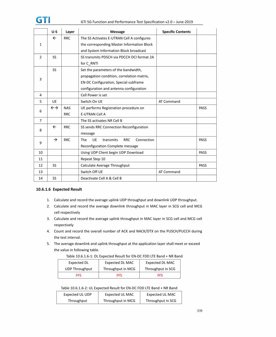
GTI 5G Function and Performance Test Specification v2.0 – June-2019
339
U-S Layer Message Specific Contents
1
RRC The SS Activates E-UTRAN Cell A configures
the corresponding Master Information Block
and System Information Block broadcast
2 SS SS transmits PDSCH via PDCCH DCI format 2A
for C_RNTI
3
SS Set the parameters of the bandwidth,
propagation condition, correlation matrix,
EN-DC Configuration, Special subframe
configuration and antenna configuration
4 Cell Power is set
5 UE Switch On UE AT Command
6 NAS
RRC
UE performs Registration procedure on
E-UTRAN Cell A
PASS
7 The SS activates NR Cell B
8 RRC SS sends RRC Connection Reconfiguration
message
9 RRC The UE transmits RRC Connection
Reconfiguration Complete message
PASS
10 Using UDP Client begin UDP Download PASS
11 Repeat Step 10
12 SS Calculate Average Throughput PASS
13 Switch Off UE AT Command
14 SS Deactivate Cell A & Cell B
10.6.1.6 Expected Result
1. Calculate and record the average uplink UDP throughput and downlink UDP throughput.
2. Calculate and record the average downlink throughput in MAC layer in SCG cell and MCG
cell respectively
3. Calculate and record the average uplink throughput in MAC layer in SCG cell and MCG cell
respectively
4. Count and record the overall number of ACK and NACK/DTX on the PUSCH/PUCCH during
the test interval.
5. The average downlink and uplink throughput at the application layer shall meet or exceed
the value in following table.
Table 10.6.1.6-1: DL Expected Result for EN-DC FDD LTE Band + NR Band
Expected DL
UDP Throughput
Expected DL MAC
Throughput in MCG
Expected DL MAC
Throughput in SCG
FFS FFS FFS
Table 10.6.1.6-2: UL Expected Result for EN-DC FDD LTE Band + NR Band
Expected UL UDP
Throughput
Expected UL MAC
Throughput in MCG
Expected UL MAC
Throughput in SCG

GTI 5G Function and Performance Test Specification v2.0 – June-2019
340
FFS FFS FFS
10.6.2 Bidirectional Throughput under fading channel, NSA
10.6.2.1 Test Purpose
To measure the UE application layer Bidirectional performance while downloading & uploading
simultaneously UDP based data in Conducted, fading Channel, NSA Option3, 100 MHz BW, Full
Resource Allocation, dynamic scheduling based on channel condition, data transmission on
MCG and SCG simultaneously
10.6.2.2 Reference specification
3GPP TS 36.331, 3GPP TS 36.508, 3GPP TS 36.521-1, 3GPP TS 38.331, 3GPP TS 38.508, 3GPP TS
38.521-1
10.6.2.3 Applicability
This test applies to Type 1 and Type 3 devices as described in clause 4.2..
10.6.2.4 Test conditions
[SS configuration]
E-UTRAN Cell A,
NR-RAN Cell B
E-UTRAN Cell A,
Cell Id=01 TAC = 01
MCC = 460 MNC = 00
EARFCN= f1
rootSequenceIndex = 0
RB Allocation UL= Full
RB Allocation DL = Full
simultaneousAckNackAndCQI = TRUE
CPConfig = UL: Normal CP/DL: Normal CP
NR-RAN Cell B,
Cell Id=02 TAC = 01
NR-ARFCN= f1
rootSequenceIndex = 0
RB Allocation UL= Full
RB Allocation DL = Full
simultaneousAckNackAndCQI = TRUE
CPConfig = UL: Normal CP/DL: Normal CP
[Common conditions]

GTI 5G Function and Performance Test Specification v2.0 – June-2019
341
Common conditions include a set of test points the UE needs to be tested in and the common
test parameters for each transmission mode.
Table 10.6.2.4-1: Test Points Configuration
Test Point Propagation
Conditions
Correlation
Matrices
NSA-1 Fading Profile : FFS N/A
Table 10.6.2.4-2: Test Parameters for Testing
Parameter Unit Value
Downlink power
allocation
dB -3
dB -3(Note 1)
LTE at antenna port dBm/15kHz -98
NR at antenna port
dBm/30kHz -98
Reporting mode
PUCCH 1-0
Note 1:
[UE configuration]
The test USIM shall be inserted.
The UE is in AUTOMATIC network selection mode.
[Initial conditions]
SS
Initial conditions are a set of test configurations the UE needs to be tested in and the steps
for the SS to take with the UE to reach the correct measurement state.
Configurations of LTE PDSCH and PDCCH before measurement are specified in Annex C.2 of
TS 36.521-1.
Configurations of NR PDSCH and PDCCH before measurement are specified in Annex C.2 of
TS 38.521-1.
Test Environment: Normal, as defined in TS 36.508 & TS 38.508-1 clause 4.1 for LTE & NR
respectively.
Frequencies to be tested: Mid Range, as defined in TS 36.508 & TS 38.508-1 for LTE & NR
respectively.
1. Connect the LTE SS, the faders and AWGN noise sources to the UE antenna connectors
as shown in TS 36.508 Annex A, Figure A.10 for antenna configuration 2x2.
2. Connect the NR SS, the faders and AWGN noise sources to the UE antenna connectors
as shown in TS 38.508-1 Annex A, Figure A.3.2.1.5 for antenna configuration 4x4.
3. Connect an application server to the IP output of the SS configured with a UDP server.
A
B
ocN
ocN
1BP
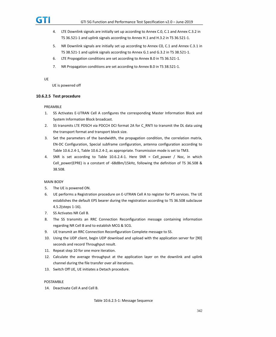
GTI 5G Function and Performance Test Specification v2.0 – June-2019
342
4. LTE Downlink signals are initially set up according to Annex C.0, C.1 and Annex C.3.2 in
TS 36.521-1 and uplink signals according to Annex H.1 and H.3.2 in TS 36.521-1.
5. NR Downlink signals are initially set up according to Annex C0, C.1 and Annex C.3.1 in
TS 38.521-1 and uplink signals according to Annex G.1 and G.3.2 in TS 38.521-1.
6. LTE Propogation conditions are set according to Annex B.0 in TS 36.521-1.
7. NR Propagation conditions are set according to Annex B.0 in TS 38.521-1.
UE
UE is powered off
10.6.2.5 Test procedure
PREAMBLE
1. SS Activates E-UTRAN Cell A configures the corresponding Master Information Block and
System Information Block broadcast.
2. SS transmits LTE PDSCH via PDCCH DCI format 2A for C_RNTI to transmit the DL data using
the transport format and transport block size.
3. Set the parameters of the bandwidth, the propagation condition, the correlation matrix,
EN-DC Configuration, Special subframe configuration, antenna configuration according to
Table 10.6.2.4-1, Table 10.6.2.4-2, as appropriate. Transmission mode is set to TM3.
4. SNR is set according to Table 10.6.2.4-1. Here SNR = Cell_power / Noc, in which
Cell_power(EPRE) is a constant of -68dBm/15kHz, following the definition of TS 36.508 &
38.508.
MAIN BODY
5. The UE is powered ON.
6. UE performs a Registration procedure on E-UTRAN Cell A to register for PS services. The UE
establishes the default EPS bearer during the registration according to TS 36.508 subclause
4.5.2(steps 1-16).
7. SS Activates NR Cell B.
8. The SS transmits an RRC Connection Reconfiguration message containing information
regarding NR Cell B and to establish MCG & SCG.
9. UE transmit an RRC Connection Reconfiguration Complete message to SS.
10. Using the UDP client, begin UDP download and upload with the application server for [90]
seconds and record Throughput result.
11. Repeat step 10 for one more iteration.
12. Calculate the average throughput at the application layer on the downlink and uplink
channel during the file transfer over all iterations.
13. Switch Off UE, UE initiates a Detach procedure.
POSTAMBLE
14. Deactivate Cell A and Cell B.
Table 10.6.2.5-1: Message Sequence

GTI 5G Function and Performance Test Specification v2.0 – June-2019
343
Step Message Sequence Verdict
U-S Layer Message Specific Contents
1
RRC The SS Activates E-UTRAN Cell A configures
the corresponding Master Information Block
and System Information Block broadcast
2 SS SS transmits PDSCH via PDCCH DCI format 2A
for C_RNTI
3
SS Set the parameters of the bandwidth,
propagation condition, correlation matrix,
EN-DC Configuration, Special subframe
configuration and antenna configuration
4 Cell Power is set
5 UE Switch On UE AT Command
6 NAS
RRC
UE performs Registration procedure on
E-UTRAN Cell A
PASS
7 The SS activates NR Cell B
8 RRC SS sends RRC Connection Reconfiguration
message
9 RRC The UE transmits RRC Connection
Reconfiguration Complete message
PASS
10 Using UDP Client begin UDP Download PASS
11 Repeat Step 10
12 SS Calculate Average Throughput PASS
13 Switch Off UE AT Command
14 SS Deactivate Cell A & Cell B
10.6.2.6 Expected Result
1. Calculate and record the average uplink UDP throughput and downlink UDP throughput.
2. Calculate and record the average downlink throughput in MAC layer in SCG cell and MCG
cell respectively
3. Calculate and record the average uplink throughput in MAC layer in SCG cell and MCG cell
respectively
4. Count and record the overall number of ACK and NACK/DTX on the PUSCH/PUCCH during
the test interval.
5. The average downlink and uplink throughput at the application layer shall meet or exceed
the value in following table.
Table 10.6.2.6-1: DL Expected Result for EN-DC FDD LTE Band + NR Band
Expected DL
UDP Throughput
Expected DL MAC
Throughput in MCG
Expected DL MAC
Throughput in SCG
FFS FFS FFS
Table 10.6.2.6-2: UL Expected Result for EN-DC FDD LTE Band + NR Band
Expected UL UDP Expected UL MAC Expected UL MAC

GTI 5G Function and Performance Test Specification v2.0 – June-2019
344
Throughput Throughput in MCG Throughput in SCG
FFS FFS FFS
10.6.3 Bidirectional Throughput under static channel on SCG, UL 64QAM, NSA
10.6.3.1 Test Purpose
To measure the UE application layer Bidirectional performance while downloading & uploading
simultaneously UDP based data in Conducted, Static Channel, NSA Option3, 100 MHz BW, Full
Resource Allocation, DL NR 256QAM+4*4 MIMO, UL NR 64QAM,data transmission on SCG
10.6.3.2 Reference specification
3GPP TS 36.331, 3GPP TS 36.508, 3GPP TS 36.521-1, 3GPP TS 38.331, 3GPP TS 38.508, 3GPP TS
38.521-1
10.6.3.3 Applicability
This test applies to Type 1 and Type 3 devices as described in clause 4.2.
10.6.3.4 Test conditions
[SS configuration]
E-UTRAN Cell A,
NR-RAN Cell B
E-UTRAN Cell A,
Cell Id=01 TAC = 01
MCC = 460 MNC = 00
EARFCN= f1
rootSequenceIndex = 0
DL Modulation / Coding = 10
RB Allocation UL= Full
RB Allocation DL = Full
simultaneousAckNackAndCQI = TRUE
CPConfig = UL: Normal CP/DL: Normal CP
NR-RAN Cell B,
Cell Id=02 TAC = 01
NR-ARFCN= f1
rootSequenceIndex = 0
DL Modulation / Coding = 27
UL Modulation / Coding = 28
RB Allocation UL= Full
RB Allocation DL = Full
simultaneousAckNackAndCQI = TRUE

GTI 5G Function and Performance Test Specification v2.0 – June-2019
345
enable4x4MIMO = TRUE
enableDL256QAM = TRUE
enableUL64QAM = TRUE
CPConfig = UL: Normal CP/DL: Normal CP
[Common conditions]
Common conditions include a set of test points the UE needs to be tested in and the common
test parameters for each transmission mode.
Table 10.6.3.4-1: Test Points Configuration
Test Point Propagation Conditions Correlation Matrices
NSA-1 Static N/A
Table 10.6.3.4-2: Test Parameters for Testing
Parameter Unit Value
Downlink power
allocation
dB -3
dB -3(Note 1)
LTE at antenna port dBm/15kHz -98
NR at antenna port dBm/30kHz -98
Reporting mode
PUCCH 1-0
Note 1:
[UE configuration]
The test USIM shall be inserted.
The UE is in AUTOMATIC network selection mode.
[Initial conditions]
SS
Initial conditions are a set of test configurations the UE needs to be tested in and the steps
for the SS to take with the UE to reach the correct measurement state.
Configurations of LTE PDSCH and PDCCH before measurement are specified in Annex C.2 of
TS 36.521-1.
Configurations of NR PDSCH and PDCCH before measurement are specified in Annex C.2 of
TS 38.521-1.
Test Environment: Normal, as defined in TS 36.508 & TS 38.508-1 clause 4.1 for LTE & NR
respectively.
8. Connect the LTE SS, the faders and AWGN noise sources to the UE antenna connectors
as shown in TS 36.508 Annex A, Figure A.10 for antenna configuration 2x2.
9. Connect the NR SS, the faders and AWGN noise sources to the UE antenna connectors
as shown in TS 36.508-1 Annex A, Figure A.3.2.1.5 for antenna configuration 4x4.
A
B
ocN
ocN
1BP
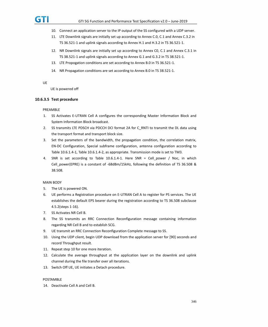
GTI 5G Function and Performance Test Specification v2.0 – June-2019
346
10. Connect an application server to the IP output of the SS configured with a UDP server.
11. LTE Downlink signals are initially set up according to Annex C.0, C.1 and Annex C.3.2 in
TS 36.521-1 and uplink signals according to Annex H.1 and H.3.2 in TS 36.521-1.
12. NR Downlink signals are initially set up according to Annex C0, C.1 and Annex C.3.1 in
TS 38.521-1 and uplink signals according to Annex G.1 and G.3.2 in TS 38.521-1.
13. LTE Propogation conditions are set according to Annex B.0 in TS 36.521-1.
14. NR Propagation conditions are set according to Annex B.0 in TS 38.521-1.
UE
UE is powered off
10.6.3.5 Test procedure
PREAMBLE
1. SS Activates E-UTRAN Cell A configures the corresponding Master Information Block and
System Information Block broadcast.
2. SS transmits LTE PDSCH via PDCCH DCI format 2A for C_RNTI to transmit the DL data using
the transport format and transport block size.
3. Set the parameters of the bandwidth, the propagation condition, the correlation matrix,
EN-DC Configuration, Special subframe configuration, antenna configuration according to
Table 10.6.1.4-1, Table 10.6.1.4-2, as appropriate. Transmission mode is set to TM3.
4. SNR is set according to Table 10.6.1.4-1. Here SNR = Cell_power / Noc, in which
Cell_power(EPRE) is a constant of -68dBm/15kHz, following the definition of TS 36.508 &
38.508.
MAIN BODY
5. The UE is powered ON.
6. UE performs a Registration procedure on E-UTRAN Cell A to register for PS services. The UE
establishes the default EPS bearer during the registration according to TS 36.508 subclause
4.5.2(steps 1-16).
7. SS Activates NR Cell B.
8. The SS transmits an RRC Connection Reconfiguration message containing information
regarding NR Cell B and to establish SCG.
9. UE transmit an RRC Connection Reconfiguration Complete message to SS.
10. Using the UDP client, begin UDP download from the application server for [90] seconds and
record Throughput result.
11. Repeat step 10 for one more iteration.
12. Calculate the average throughput at the application layer on the downlink and uplink
channel during the file transfer over all iterations.
13. Switch Off UE, UE initiates a Detach procedure.
POSTAMBLE
14. Deactivate Cell A and Cell B.

GTI 5G Function and Performance Test Specification v2.0 – June-2019
347
Table 10.6.3.5-1: Message Sequence
Step Message Sequence Verdict
U-S Layer Message Specific Contents
1
RRC The SS Activates E-UTRAN Cell A configures
the corresponding Master Information Block
and System Information Block broadcast
2 SS SS transmits PDSCH via PDCCH DCI format 2A
for C_RNTI
3
SS Set the parameters of the bandwidth,
propagation condition, correlation matrix,
EN-DC Configuration, Special subframe
configuration and antenna configuration
4 Cell Power is set
5 UE Switch On UE AT Command
6 NAS
RRC
UE performs Registration procedure on
E-UTRAN Cell A
PASS
7 The SS activates NR Cell B
8 RRC SS sends RRC Connection Reconfiguration
message
9 RRC The UE transmits RRC Connection
Reconfiguration Complete message
PASS
10 Using UDP Client begin UDP Download PASS
11 Repeat Step 10
12 SS Calculate Average Throughput PASS
13 Switch Off UE AT Command
14 SS Deactivate Cell A & Cell B
10.6.3.6 Expected Result
1. Calculate and record the average uplink UDP throughput and downlink UDP throughput.
2. Calculate and record the average downlink throughput in MAC layer in SCG cell
3. Calculate and record the average uplink throughput in MAC layer in SCG cell
4. Count and record the overall number of ACK and NACK/DTX on the PUSCH/PUCCH during
the test interval.
5. The average downlink and uplink throughput at the application layer shall meet or exceed
the value in following table.
Table 10.6.3.6-1: DL Expected Result for EN-DC FDD LTE Band + NR Band
Expected DL UDP Throughput Expected DL MAC Throughput in SCG
[1.7Gbps] [1.7Gbps]
Table 10.6.3.6-2: UL Expected Result for EN-DC FDD LTE Band + NR Band
Expected UL UDP Throughput Expected UL MAC Throughput in SCG
[95Mbps] [95Mbps]

GTI 5G Function and Performance Test Specification v2.0 – June-2019
348
10.6.4 Bidirectional Throughput under static channel on SCG, UL 256QAM, NSA
10.6.4.1 Test Purpose
To measure the UE application layer Bidirectional performance while downloading & uploading
simultaneously UDP based data in Conducted, Static Channel, NSA Option3, 100 MHz BW, Full
Resource Allocation, DL NR 256QAM+4*4 MIMO, UL NR 256QAM,data transmission on SCG
10.6.4.2 Reference specification
3GPP TS 36.331, 3GPP TS 36.508, 3GPP TS 36.521-1, 3GPP TS 38.331, 3GPP TS 38.508, 3GPP TS
38.521-1
10.6.4.3 Applicability
This test applies to Type 1 and Type 3 devices as described in clause 4.2.
10.6.4.4 Test conditions
[SS configuration]
E-UTRAN Cell A,
NR-RAN Cell B
E-UTRAN Cell A,
Cell Id=01 TAC = 01
MCC = 460 MNC = 00
EARFCN= f1
rootSequenceIndex = 0
DL Modulation / Coding = 10
RB Allocation UL= Full
RB Allocation DL = Full
simultaneousAckNackAndCQI = TRUE
CPConfig = UL: Normal CP/DL: Normal CP
NR-RAN Cell B,
Cell Id=02 TAC = 01
NR-ARFCN= f1
rootSequenceIndex = 0
DL Modulation / Coding = 27
UL Modulation / Coding = 27
RB Allocation UL= Full
RB Allocation DL = Full
simultaneousAckNackAndCQI = TRUE
enable4x4MIMO = TRUE
enableDL256QAM = TRUE
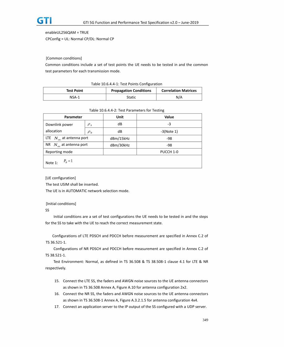
GTI 5G Function and Performance Test Specification v2.0 – June-2019
349
enableUL256QAM = TRUE
CPConfig = UL: Normal CP/DL: Normal CP
[Common conditions]
Common conditions include a set of test points the UE needs to be tested in and the common
test parameters for each transmission mode.
Table 10.6.4.4-1: Test Points Configuration
Test Point Propagation Conditions Correlation Matrices
NSA-1 Static N/A
Table 10.6.4.4-2: Test Parameters for Testing
Parameter Unit Value
Downlink power
allocation
dB -3
dB -3(Note 1)
LTE at antenna port dBm/15kHz -98
NR at antenna port dBm/30kHz -98
Reporting mode
PUCCH 1-0
Note 1:
[UE configuration]
The test USIM shall be inserted.
The UE is in AUTOMATIC network selection mode.
[Initial conditions]
SS
Initial conditions are a set of test configurations the UE needs to be tested in and the steps
for the SS to take with the UE to reach the correct measurement state.
Configurations of LTE PDSCH and PDCCH before measurement are specified in Annex C.2 of
TS 36.521-1.
Configurations of NR PDSCH and PDCCH before measurement are specified in Annex C.2 of
TS 38.521-1.
Test Environment: Normal, as defined in TS 36.508 & TS 38.508-1 clause 4.1 for LTE & NR
respectively.
15. Connect the LTE SS, the faders and AWGN noise sources to the UE antenna connectors
as shown in TS 36.508 Annex A, Figure A.10 for antenna configuration 2x2.
16. Connect the NR SS, the faders and AWGN noise sources to the UE antenna connectors
as shown in TS 36.508-1 Annex A, Figure A.3.2.1.5 for antenna configuration 4x4.
17. Connect an application server to the IP output of the SS configured with a UDP server.
A
B
ocN
ocN
1BP

GTI 5G Function and Performance Test Specification v2.0 – June-2019
350
18. LTE Downlink signals are initially set up according to Annex C.0, C.1 and Annex C.3.2 in
TS 36.521-1 and uplink signals according to Annex H.1 and H.3.2 in TS 36.521-1.
19. NR Downlink signals are initially set up according to Annex C0, C.1 and Annex C.3.1 in
TS 38.521-1 and uplink signals according to Annex G.1 and G.3.2 in TS 38.521-1.
20. LTE Propogation conditions are set according to Annex B.0 in TS 36.521-1.
21. NR Propagation conditions are set according to Annex B.0 in TS 38.521-1.
UE
UE is powered off
10.6.4.5 Test procedure
PREAMBLE
15. SS Activates E-UTRAN Cell A configures the corresponding Master Information Block and
System Information Block broadcast.
16. SS transmits LTE PDSCH via PDCCH DCI format 2A for C_RNTI to transmit the DL data using
the transport format and transport block size.
17. Set the parameters of the bandwidth, the propagation condition, the correlation matrix,
EN-DC Configuration, Special subframe configuration, antenna configuration according to
Table 10.6.1.4-1, Table 10.6.1.4-2, as appropriate. Transmission mode is set to TM3.
18. SNR is set according to Table 10.6.1.4-1. Here SNR = Cell_power / Noc, in which
Cell_power(EPRE) is a constant of -68dBm/15kHz, following the definition of TS 36.508 &
38.508.
MAIN BODY
19. The UE is powered ON.
20. UE performs a Registration procedure on E-UTRAN Cell A to register for PS services. The UE
establishes the default EPS bearer during the registration according to TS 36.508 subclause
4.5.2(steps 1-16).
21. SS Activates NR Cell B.
22. The SS transmits an RRC Connection Reconfiguration message containing information
regarding NR Cell B and to establish SCG.
23. UE transmit an RRC Connection Reconfiguration Complete message to SS.
24. Using the UDP client, begin UDP download from the application server for [90] seconds and
record Throughput result.
25. Repeat step 10 for one more iteration.
26. Calculate the average throughput at the application layer on the downlink and uplink
channel during the file transfer over all iterations.
27. Switch Off UE, UE initiates a Detach procedure.
POSTAMBLE
28. Deactivate Cell A and Cell B.

GTI 5G Function and Performance Test Specification v2.0 – June-2019
351
Table 10.6.4.5-1: Message Sequence
Step Message Sequence Verdict
U-S Layer Message Specific Contents
1
RRC The SS Activates E-UTRAN Cell A configures
the corresponding Master Information Block
and System Information Block broadcast
2 SS SS transmits PDSCH via PDCCH DCI format 2A
for C_RNTI
3
SS Set the parameters of the bandwidth,
propagation condition, correlation matrix,
EN-DC Configuration, Special subframe
configuration and antenna configuration
4 Cell Power is set
5 UE Switch On UE AT Command
6 NAS
RRC
UE performs Registration procedure on
E-UTRAN Cell A
PASS
7 The SS activates NR Cell B
8 RRC SS sends RRC Connection Reconfiguration
message
9 RRC The UE transmits RRC Connection
Reconfiguration Complete message
PASS
10 Using UDP Client begin UDP Download PASS
11 Repeat Step 10
12 SS Calculate Average Throughput PASS
13 Switch Off UE AT Command
14 SS Deactivate Cell A & Cell B
10.6.4.6 Expected Result
1. Calculate and record the average uplink UDP throughput and downlink UDP throughput.
2. Calculate and record the average downlink throughput in MAC layer in SCG cell
3. Calculate and record the average uplink throughput in MAC layer in SCG cell
4. Count and record the overall number of ACK and NACK/DTX on the PUSCH/PUCCH during
the test interval.
5. The average downlink and uplink throughput at the application layer shall meet or exceed
the value in following table.
Table 10.6.4.6-1: DL Expected Result for EN-DC FDD LTE Band + NR Band
Expected DL UDP Throughput Expected DL MAC Throughput in SCG
[1.7Gbps] [1.7Gbps]
Table 10.6.4.6-2: UL Expected Result for EN-DC FDD LTE Band + NR Band
Expected UL UDP Throughput Expected UL MAC Throughput in SCG
[125Mbps] [125Mbps]

GTI 5G Function and Performance Test Specification v2.0 – June-2019
352
10.6.5 Bidirectional Throughput under fading channel on SCG, NSA
10.6.5.1 Test Purpose
To measure the UE application layer Bidirectional performance while downloading & uploading
simultaneously UDP based data in Conducted, Static Channel, NSA Option3, 100 MHz BW, Full
Resource Allocation, dynamic scheduling based on channel condition, data transmission on SCG
10.6.5.2 Reference specification
3GPP TS 36.331, 3GPP TS 36.508, 3GPP TS 36.521-1, 3GPP TS 38.331, 3GPP TS 38.508, 3GPP TS
38.521-1
10.6.5.3 Applicability
This test applies to Type 1 and Type 3 devices as described in clause 4.2..
10.6.5.4 Test conditions
[SS configuration]
E-UTRAN Cell A,
NR-RAN Cell B
E-UTRAN Cell A,
Cell Id=01 TAC = 01
MCC = 460 MNC = 00
EARFCN= f1
rootSequenceIndex = 0
RB Allocation UL= Full
RB Allocation DL = Full
simultaneousAckNackAndCQI = TRUE
CPConfig = UL: Normal CP/DL: Normal CP
NR-RAN Cell B,
Cell Id=02 TAC = 01
NR-ARFCN= f1
rootSequenceIndex = 0
RB Allocation UL= Full
RB Allocation DL = Full
simultaneousAckNackAndCQI = TRUE
CPConfig = UL: Normal CP/DL: Normal CP
[Common conditions]
Common conditions include a set of test points the UE needs to be tested in and the common
test parameters for each transmission mode.

GTI 5G Function and Performance Test Specification v2.0 – June-2019
353
Table 10.6.5.4-1: Test Points Configuration
Test Point Propagation
Conditions
Correlation
Matrices
NSA-1 Fading Profile : FFS N/A
Table 10.6.5.4-2: Test Parameters for Testing
Parameter Unit Value
Downlink power
allocation
dB -3
dB -3(Note 1)
LTE at antenna port dBm/15kHz -98
NR at antenna port
dBm/30kHz -98
Reporting mode
PUCCH 1-0
Note 1:
[UE configuration]
The test USIM shall be inserted.
The UE is in AUTOMATIC network selection mode.
[Initial conditions]
SS
Initial conditions are a set of test configurations the UE needs to be tested in and the steps
for the SS to take with the UE to reach the correct measurement state.
Configurations of LTE PDSCH and PDCCH before measurement are specified in Annex C.2 of
TS 36.521-1.
Configurations of NR PDSCH and PDCCH before measurement are specified in Annex C.2 of
TS 38.521-1.
Test Environment: Normal, as defined in TS 36.508 & TS 38.508-1 clause 4.1 for LTE & NR
respectively.
Frequencies to be tested: Mid Range, as defined in TS 36.508 & TS 38.508-1 for LTE & NR
respectively.
8. Connect the LTE SS, the faders and AWGN noise sources to the UE antenna connectors
as shown in TS 36.508 Annex A, Figure A.10 for antenna configuration 2x2.
9. Connect the NR SS, the faders and AWGN noise sources to the UE antenna connectors
as shown in TS 38.508-1 Annex A, Figure A.3.2.1.5 for antenna configuration 4x4.
10. Connect an application server to the IP output of the SS configured with a UDP server.
11. LTE Downlink signals are initially set up according to Annex C.0, C.1 and Annex C.3.2 in
TS 36.521-1 and uplink signals according to Annex H.1 and H.3.2 in TS 36.521-1.
A
B
ocN
ocN
1BP

GTI 5G Function and Performance Test Specification v2.0 – June-2019
354
12. NR Downlink signals are initially set up according to Annex C0, C.1 and Annex C.3.1 in
TS 38.521-1 and uplink signals according to Annex G.1 and G.3.2 in TS 38.521-1.
13. LTE Propogation conditions are set according to Annex B.0 in TS 36.521-1.
14. NR Propagation conditions are set according to Annex B.0 in TS 38.521-1.
UE
UE is powered off
10.6.5.5 Test procedure
PREAMBLE
15. SS Activates E-UTRAN Cell A configures the corresponding Master Information Block and
System Information Block broadcast.
16. SS transmits LTE PDSCH via PDCCH DCI format 2A for C_RNTI to transmit the DL data using
the transport format and transport block size.
17. Set the parameters of the bandwidth, the propagation condition, the correlation matrix,
EN-DC Configuration, Special subframe configuration, antenna configuration according to
Table 10.6.2.4-1, Table 10.6.2.4-2, as appropriate. Transmission mode is set to TM3.
18. SNR is set according to Table 10.6.2.4-1. Here SNR = Cell_power / Noc, in which
Cell_power(EPRE) is a constant of -68dBm/15kHz, following the definition of TS 36.508 &
38.508.
MAIN BODY
19. The UE is powered ON.
20. UE performs a Registration procedure on E-UTRAN Cell A to register for PS services. The UE
establishes the default EPS bearer during the registration according to TS 36.508 subclause
4.5.2(steps 1-16).
21. SS Activates NR Cell B.
22. The SS transmits an RRC Connection Reconfiguration message containing information
regarding NR Cell B and to establish SCG.
23. UE transmit an RRC Connection Reconfiguration Complete message to SS.
24. Using the UDP client, begin UDP download and upload with the application server for [90]
seconds and record Throughput result.
25. Repeat step 10 for one more iteration.
26. Calculate the average throughput at the application layer on the downlink and uplink
channel during the file transfer over all iterations.
27. Switch Off UE, UE initiates a Detach procedure.
POSTAMBLE
28. Deactivate Cell A and Cell B.
Table 10.6.5.5-1: Message Sequence
Step Message Sequence Verdict
U-S Layer Message Specific Contents

GTI 5G Function and Performance Test Specification v2.0 – June-2019
355
1
RRC The SS Activates E-UTRAN Cell A configures
the corresponding Master Information Block
and System Information Block broadcast
2 SS SS transmits PDSCH via PDCCH DCI format 2A
for C_RNTI
3
SS Set the parameters of the bandwidth,
propagation condition, correlation matrix,
EN-DC Configuration, Special subframe
configuration and antenna configuration
4 Cell Power is set
5 UE Switch On UE AT Command
6 NAS
RRC
UE performs Registration procedure on
E-UTRAN Cell A
PASS
7 The SS activates NR Cell B
8 RRC SS sends RRC Connection Reconfiguration
message
9 RRC The UE transmits RRC Connection
Reconfiguration Complete message
PASS
10 Using UDP Client begin UDP Download PASS
11 Repeat Step 10
12 SS Calculate Average Throughput PASS
13 Switch Off UE AT Command
14 SS Deactivate Cell A & Cell B
10.6.5.6 Expected Result
6. Calculate and record the average uplink UDP throughput and downlink UDP throughput.
7. Calculate and record the average downlink throughput in MAC layer in SCG cell
8. Calculate and record the average uplink throughput in MAC layer in SCG cell
9. Count and record the overall number of ACK and NACK/DTX on the PUSCH/PUCCH during
the test interval.
10. The average downlink and uplink throughput at the application layer shall meet or exceed
the value in following table.
Table 10.6.5.6-1: DL Expected Result for EN-DC FDD LTE Band + NR Band
Expected DL
UDP Throughput
Expected DL MAC
Throughput in SCG
FFS FFS
Table 10.6.5.6-2: UL Expected Result for EN-DC FDD LTE Band + NR Band
Expected UL UDP
Throughput
Expected UL MAC
Throughput in SCG
FFS FFS

GTI 5G Function and Performance Test Specification v2.0 – June-2019
356
11 Latency
11.1 Latency Basic Tests
11.1.1 Control Plane Latency – Basic Test
11.1.1.1 Test Purpose
Calculate the latency for different signaling messages exchange between SS and UE
11.1.1.2 Reference specification
TS 38.304, TS 38.331, TS 38.300
11.1.1.3 Applicability
This test applies to the device that supports SA or SA+NSA.
11.1.1.4 Test conditions
[SS configuration]
Cell A is a NR Cell.
Cell A supports only SA
NR Cell A
Cell Id=01 TAC = 01
MCC = 460 MNC = 00
NR Band = n41
NR-ARFCN= f1
Bandwidth = 100 MHz
SS/PBCH SSS EPRE = -125 dBm/30kHz
[UE configuration]
The test UICC with USIM should be inserted
The UE is in AUTOMATIC network selection mode.
UE works in SA mode.
[Initial conditions]
SS
NR Cell A is not active
The test shall be performed under ideal radio conditions.
UE
UE is powered off

GTI 5G Function and Performance Test Specification v2.0 – June-2019
357
11.1.1.5 Test procedure
Table 5.1.1.5-1: Time of cell power level and parameter changes
Time NR
Cell A
Remark
T0 -75
PREAMBLE
1. Activate NR Cell A.The SS configures the corresponding Master Information Block and System
Information Block broadcast.
2. The SS configures the initial power according to T0 in Table 11.1.5-1.
3. The UE is powered ON.
4. The UE performs the registration procedure on Cell A (see 38.508, Table 4.5.2.2-2 till Step
20a1 ).
MAIN BODY
5. SS initiates paging message to UE
6. UE initiates the Rach Procedure to start the service request procedure
7. Calculte the time taken between the Rach Request to Msg4
8. SS transmits RRC Setup message to UE
9. UE sends RRC Setup Complete with Service Request NAS message
10. SS sends the Access stratum Security Mode Command to the UE
11. UE responds with AS Security Mode Complete to the SS
12. Calculate the time taken between Security Mode Command and Security Mode Complete
13. SS Transmits RRC Reconfiguration to establish SRB2 and DRB with a Service accept NAS
message
14. UE sends RRC Reconfiguration Complete to the SS
15. The RRC connection is released by the SS. The UE enters Registered, Idle Mode
16. Repeat Steps 5 to 15 for 4 times(on 4th
iteration skip 15th
step for initiating Deregistration –
POSTAMBLE step)
17. Calculate the average time taken at step 7 and step 12
POSTAMBLE
18. The SS initiates a Deregitration procedure.
19. The SS initiates a RRC release procedure.
20. Deactivate NR Cell A.
Table 5.1.1.5-2: Message Sequence
Step Message Sequence Verdict
U-S Layer Message Specific Contents
Connect the power consumption tester to

GTI 5G Function and Performance Test Specification v2.0 – June-2019
358
the UE
1 RRC Activate NR Cell A.
2 SS configures the initial power according to
T0 in Table 11.1.5-1.
3 UE Switch On UE AT Command
4
NAS
RRC
UE performs the registration procedure (see
38.508, Table 4.5.2.2-2 till Step 20a1 ).
PASS
5 RRC Paging
6
RRC/
MAC
Rach Procedure to start the Service Request
Procedure till msg4
PASS
7 Calculate the time taken between Rach
Request to Msg4
8 RRC RRCSetup
9 NAS
RRC
RRCSetupComplete with Service Request NAS
message
10 RRC AS Security Mode Command
11 RRC AS Security Mode Complete
12 Calculate the time taken between Step 10
and Step 11
13 NAS
RRC
RRCReconfiguration with Service Accept NAS
message
14 RRC RRCReconfigurationComplete PASS
15 RRC RRCRelease
16 Repeat Steps 5 to Step 15 for 4 times(on 4th
iteration skip Step 15)
17 Calculate the average time taken at Step 7
and Step 12
18
NAS SS initiates a Deregitration procedure. PASS
19 RRC SS initiates a RRC release procedure.
20 Deactivate NR Cell A.
11.1.1.6 Expected Result
The Average time taken for RACH procedure should be less than [TBD]ms.
The Average time taken for RRC Signaling message pair should be less than [TBD]ms.
11.1.2 User Plane Latency – Basic Test
11.1.2.1 Test Purpose
Calculate the latency of User plane data exchange between SS and UE

GTI 5G Function and Performance Test Specification v2.0 – June-2019
359
11.1.2.2 Reference specification
TS 38.304, TS 38.331, TS 38.300
11.1.2.3 Applicability
This test applies to the device that supports SA or SA+NSA.
11.1.2.4 Test conditions
[SS configuration]
Cell A is a NR Cell.
Cell A supports only SA
NR Cell A
Cell Id=01 TAC = 01
MCC = 460 MNC = 00
NR Band = n41
NR-ARFCN= f1
Bandwidth = 100 MHz
SS/PBCH SSS EPRE = -125 dBm/30kHz
[UE configuration]
The test UICC with USIM should be inserted
The UE is in AUTOMATIC network selection mode.
UE works in SA mode.
[Initial conditions]
SS
NR Cell A is not active
The test shall be performed under ideal radio conditions.
UE
UE is powered off
11.1.2.5 Test procedure
Table 5.1.1.55-1: Time of cell power level and parameter changes
Time NR
Cell A
Remark
T0 -75
PREAMBLE
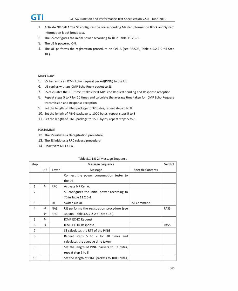
GTI 5G Function and Performance Test Specification v2.0 – June-2019
360
1. Activate NR Cell A.The SS configures the corresponding Master Information Block and System
Information Block broadcast.
2. The SS configures the initial power according to T0 in Table 11.2.5-1.
3. The UE is powered ON.
4. The UE performs the registration procedure on Cell A (see 38.508, Table 4.5.2.2-2 till Step
18 ).
MAIN BODY
5. SS Transmits an ICMP Echo Request packet(PING) to the UE
6. UE replies with an ICMP Echo Reply packet to SS
7. SS calculates the RTT time it takes for ICMP Echo Request sending and Response reception
8. Repeat steps 5 to 7 for 10 times and calculate the average time taken for ICMP Echo Requese
transmission and Response reception
9. Set the length of PING package to 32 bytes, repeat steps 5 to 8
10. Set the length of PING package to 1000 bytes, repeat steps 5 to 8
11. Set the length of PING package to 1500 bytes, repeat steps 5 to 8
POSTAMBLE
12. The SS initiates a Deregitration procedure.
13. The SS initiates a RRC release procedure.
14. Deactivate NR Cell A.
Table 5.1.1.5-2: Message Sequence
Step Message Sequence Verdict
U-S Layer Message Specific Contents
Connect the power consumption tester to
the UE
1 RRC Activate NR Cell A.
2 SS configures the initial power according to
T0 in Table 11.2.5-1.
3 UE Switch On UE AT Command
4
NAS
RRC
UE performs the registration procedure (see
38.508, Table 4.5.2.2-2 till Step 18 ).
PASS
5 ICMP ECHO Request
6 ICMP ECHO Response PASS
7 SS calculates the RTT of the PING
8 Repeat steps 5 to 7 for 10 times and
calculates the average time taken
9 Set the length of PING packets to 32 bytes,
repeat step 5 to 8
10 Set the length of PING packets to 1000 bytes,

GTI 5G Function and Performance Test Specification v2.0 – June-2019
361
repeat step 5 to 8
11 Set the length of PING packets to 1500 bytes,
repeat step 5 to 8
12
NAS SS initiates a Deregitration procedure. PASS
13 RRC SS initiates a RRC release procedure.
14 Deactivate NR Cell A.
11.1.2.6 Expected Result
The RTT for the ICMP Echo Request and Response should be less than [TBD]ms
12 High Speed Train
13 Beam Management
Appendix A Test Channel Parameters
Appendix B Document Change Record

GTI 5G Function and Performance Test Specification v2.0 – June-2019
362
Date Meeting # Version Revision Contents
27-Nov-2018 NA 0.1 First draft release to task members to be used as
starting template.
04-Jan-2019 NA 0.2 Incorporated the following CRs:-
Anritsu-20181221-01
Anritsu-20181221-02
CMCC-20181217-01
DTG-20190101-01
Keysight-20181223-01-NSA
Keysight-20181223-02-SA
RNS-20181217-01
RNS-20181217-02
RNS-20181217-03
RNS-20181224-01
RNS-20181224-02
RNS-20181224-03
23-Jan-2019 NA 0.3 CMCC-20190120-01
23-Jan-2019 NA 0.4 Anritsu-20190115-01
Anritsu-20190115-02
Anritsu-20190115-03
Anritsu-20190115-04
DTG-20190115-01
Keysight-20190116-01
31-Jan-2019 NA 0.5 Anritsu-20190130-01
Anritsu-20190131-01
CMCC-20190130-02
DTG-20190129-01
Keysight-20190129-01
12-Feb-2019 NA 1.0 Anritsu-20190201-01
Anritsu-20190208-01
RNS-20190212-01
08-Mar-2019 NA 1.0.1 CMCC-20190304-01
DTG-20190304-01
DTG-20190306-01
22-Mar-2019 NA 1.0.2 CMCC-20190321-01
R&S-20190311-01
DTG-20190308-01
DTG-20190320-01
08-Apr-2019 NA 1.5.0 DTG-20190329-01
Keysight-20190402-01
StarPoint-20190401-01
6-May-2019 NA 1.5.1 CMCC-20190422-01
RS-20190410-01
RS-20190410-02r1

GTI 5G Function and Performance Test Specification v2.0 – June-2019
363
RS-20190412-03
30-May-2019 NA 1.5.2 CMCC-20190426-01
CMCC-20190510-01r2
CMCC-20190513-01
CMCC-20190522-01
16-Jun-2019 NA 2.0 Post GTI members review.
Updated document version number only.