Embed Size (px)
Citation preview

GTConfigLite
User’s Guide
About XantrexXantrex Technology Inc. is a world-leading supplier of advanced power electronics and controls with products from 50 watt mobile units to one MW utility-scale systems for wind, solar, batteries, fuel cells, microturbines, and backup power applications in both grid-connected and stand-alone systems. Xantrex products include inverters, battery chargers, programmable power supplies, and variable speed drives that convert, supply, control, clean, and distribute electrical power.
TrademarksGTConfigLite is a trademark of Xantrex International. Xantrex is a registered trademark of Xantrex International.Other trademarks, registered trademarks, and product names are the property of their respective owners and are used herein for identification purposes only.
Notice of CopyrightGTConfigLite User’s Guide© July 2007 Xantrex International. All rights reserved.
DisclaimerUNLESS SPECIFICALLY AGREED TO IN WRITING, XANTREX TECHNOLOGY INC. (“XANTREX”)(a) MAKES NO WARRANTY AS TO THE ACCURACY, SUFFICIENCY OR SUITABILITY OF ANY TECHNICAL OR OTHER INFORMATION PROVIDED IN ITS MANUALS OR OTHER DOCUMENTATION.(b) ASSUMES NO RESPONSIBILITY OR LIABILITY FOR LOSS OR DAMAGE, WHETHER DIRECT, INDIRECT, CONSEQUENTIAL OR INCIDENTAL, WHICH MIGHT ARISE OUT OF THE USE OF SUCH INFORMATION. THE USE OF ANY SUCH INFORMATION WILL BE ENTIRELY AT THE USER’S RISK.
Date and RevisionJuly 2007 Revision B
Part Number975-0260-01-01
Contact InformationTelephone: 1 800 670 0707 (toll free North America)
1 360 925 5097 (direct)Fax: 1 360 925 5143Email: [email protected]: www.xantrex.com
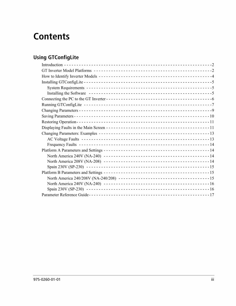
Contents
Using GTConfigLiteIntroduction - - - - - - - - - - - - - - - - - - - - - - - - - - - - - - - - - - - - - - - - - - - - - - - - - - - - - - - - - - - -2GT Inverter Model Platforms - - - - - - - - - - - - - - - - - - - - - - - - - - - - - - - - - - - - - - - - - - - - - - - -2How to Identify Inverter Models - - - - - - - - - - - - - - - - - - - - - - - - - - - - - - - - - - - - - - - - - - - - - -4Installing GTConfigLite - - - - - - - - - - - - - - - - - - - - - - - - - - - - - - - - - - - - - - - - - - - - - - - - - - - -5
System Requirements - - - - - - - - - - - - - - - - - - - - - - - - - - - - - - - - - - - - - - - - - - - - - - - - - - -5Installing the Software - - - - - - - - - - - - - - - - - - - - - - - - - - - - - - - - - - - - - - - - - - - - - - - - - -5
Connecting the PC to the GT Inverter - - - - - - - - - - - - - - - - - - - - - - - - - - - - - - - - - - - - - - - - - - -6Running GTConfigLite - - - - - - - - - - - - - - - - - - - - - - - - - - - - - - - - - - - - - - - - - - - - - - - - - - - -7Changing Parameters - - - - - - - - - - - - - - - - - - - - - - - - - - - - - - - - - - - - - - - - - - - - - - - - - - - - - -9Saving Parameters - - - - - - - - - - - - - - - - - - - - - - - - - - - - - - - - - - - - - - - - - - - - - - - - - - - - - - - 10Restoring Operation- - - - - - - - - - - - - - - - - - - - - - - - - - - - - - - - - - - - - - - - - - - - - - - - - - - - - - 11Displaying Faults in the Main Screen - - - - - - - - - - - - - - - - - - - - - - - - - - - - - - - - - - - - - - - - - - 11Changing Parameters: Examples - - - - - - - - - - - - - - - - - - - - - - - - - - - - - - - - - - - - - - - - - - - - - 13
AC Voltage Faults - - - - - - - - - - - - - - - - - - - - - - - - - - - - - - - - - - - - - - - - - - - - - - - - - - - - 13Frequency Faults - - - - - - - - - - - - - - - - - - - - - - - - - - - - - - - - - - - - - - - - - - - - - - - - - - - - - 14
Platform A Parameters and Settings - - - - - - - - - - - - - - - - - - - - - - - - - - - - - - - - - - - - - - - - - - - 14North America 240V (NA-240) - - - - - - - - - - - - - - - - - - - - - - - - - - - - - - - - - - - - - - - - - - - 14North America 208V (NA-208) - - - - - - - - - - - - - - - - - - - - - - - - - - - - - - - - - - - - - - - - - - - 14Spain 230V (SP-230) - - - - - - - - - - - - - - - - - - - - - - - - - - - - - - - - - - - - - - - - - - - - - - - - - - 15
Platform B Parameters and Settings - - - - - - - - - - - - - - - - - - - - - - - - - - - - - - - - - - - - - - - - - - - 15North America 240/208V (NA-240/208) - - - - - - - - - - - - - - - - - - - - - - - - - - - - - - - - - - - - - 15North America 240V (NA-240) - - - - - - - - - - - - - - - - - - - - - - - - - - - - - - - - - - - - - - - - - - - 16Spain 230V (SP-230) - - - - - - - - - - - - - - - - - - - - - - - - - - - - - - - - - - - - - - - - - - - - - - - - - - 16
Parameter Reference Guide- - - - - - - - - - - - - - - - - - - - - - - - - - - - - - - - - - - - - - - - - - - - - - - - - 17
975-0260-01-01 iii

iv
Using GTConfigLite
This guide contains information and procedures to configure and operate GTConfigLite, a PC-based application for modifying disconnect parameters for the Xantrex GT Solar Inverter.
Using GTConfigLite
IntroductionGTConfigLite is a software tool that allows you to change the factory settings of your GT Solar Inverter. These voltage and frequency disconnect settings form a vital part of the GT Inverter islanding protection.Since the GT Inverter feeds power to the utility grid shared by other users, it is paramount that the GT Inverter follows strict guidelines imposed by agencies and utility companies. When a fault on the grid occurs, the inverter must stop feeding power to the grid to ensure no person working on the grid is harmed by a distributed energy source. The process of preventing a device from feeding power to a disabled utility grid is called “anti-islanding.” Islanding protection is an essential GT Inverter safety feature. Default software settings are programmed into each GT Inverter at the factory to ensure it does not “island” according to relevant safety regulations (UL1741, RD1663, etc.).In some instances it may be desirable from both a utility and customer point of view to adjust these default settings. For example, the GT Inverter may experience “nuisance trips” (taking the inverter “offline”) if the grid is weak and the voltage falls outside the allowable range specified in the regulations. It may be difficult for a utility to upgrade the grid to eliminate this problem. With permission from the utility, the factory settings may be changed to allow the GT Inverter to operate over a wider grid voltage range.
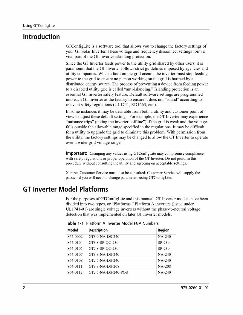
GT Inverter Model PlatformsFor the purposes of GTConfigLite and this manual, GT Inverter models have been divided into two types, or “Platforms.” Platform A inverters (listed under UL1741-01) are single voltage inverters without the phase-to-neutral voltage detection that was implemented on later GT Inverter models.
Important: Changing any values using GTConfigLite may compromise compliance with safety regulations or proper operation of the GT Inverter. Do not perform this procedure without consulting the utility and agreeing on acceptable settings.
Xantrex Customer Service must also be consulted. Customer Service will supply the password you will need to change parameters using GTConfigLite.
Table 1-1 Platform A Inverter Model FGA Numbers
Model Description Region
864-0002 GT3.0-NA-DS-240 NA-240864-0104 GT3.8-SP-QC-230 SP-230864-0105 GT2.8-SP-QC-230 SP-230864-0107 GT3.3-NA-DS-240 NA-240864-0108 GT2.5-NA-DS-240 NA-240864-0111 GT3.3-NA-DS-208 NA-208864-0112 GT2.5-NA-DS-240-POS NA-240
2 975-0260-01-01
GT Inverter Model Platforms
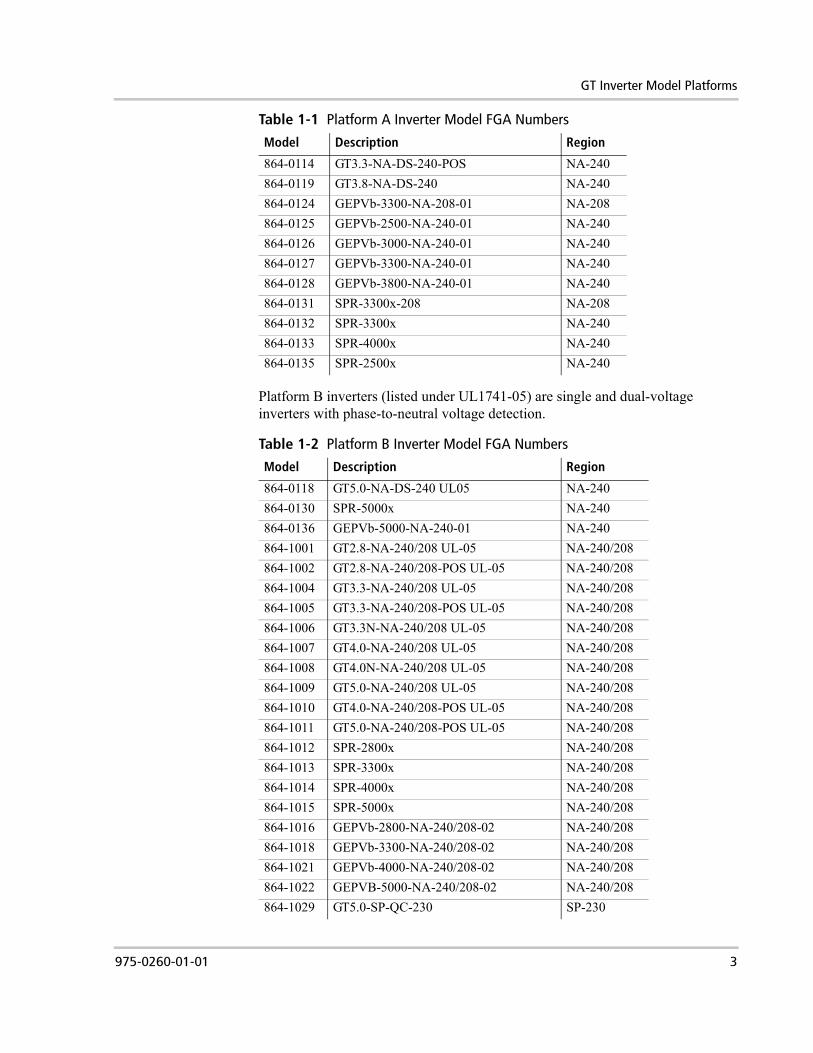
Platform B inverters (listed under UL1741-05) are single and dual-voltage inverters with phase-to-neutral voltage detection.
864-0114 GT3.3-NA-DS-240-POS NA-240864-0119 GT3.8-NA-DS-240 NA-240864-0124 GEPVb-3300-NA-208-01 NA-208864-0125 GEPVb-2500-NA-240-01 NA-240864-0126 GEPVb-3000-NA-240-01 NA-240864-0127 GEPVb-3300-NA-240-01 NA-240864-0128 GEPVb-3800-NA-240-01 NA-240864-0131 SPR-3300x-208 NA-208864-0132 SPR-3300x NA-240864-0133 SPR-4000x NA-240864-0135 SPR-2500x NA-240
Table 1-1 Platform A Inverter Model FGA Numbers
Model Description Region
Table 1-2 Platform B Inverter Model FGA Numbers
Model Description Region
864-0118 GT5.0-NA-DS-240 UL05 NA-240864-0130 SPR-5000x NA-240864-0136 GEPVb-5000-NA-240-01 NA-240864-1001 GT2.8-NA-240/208 UL-05 NA-240/208864-1002 GT2.8-NA-240/208-POS UL-05 NA-240/208864-1004 GT3.3-NA-240/208 UL-05 NA-240/208864-1005 GT3.3-NA-240/208-POS UL-05 NA-240/208864-1006 GT3.3N-NA-240/208 UL-05 NA-240/208864-1007 GT4.0-NA-240/208 UL-05 NA-240/208864-1008 GT4.0N-NA-240/208 UL-05 NA-240/208864-1009 GT5.0-NA-240/208 UL-05 NA-240/208864-1010 GT4.0-NA-240/208-POS UL-05 NA-240/208864-1011 GT5.0-NA-240/208-POS UL-05 NA-240/208864-1012 SPR-2800x NA-240/208864-1013 SPR-3300x NA-240/208864-1014 SPR-4000x NA-240/208864-1015 SPR-5000x NA-240/208864-1016 GEPVb-2800-NA-240/208-02 NA-240/208864-1018 GEPVb-3300-NA-240/208-02 NA-240/208864-1021 GEPVb-4000-NA-240/208-02 NA-240/208864-1022 GEPVB-5000-NA-240/208-02 NA-240/208864-1029 GT5.0-SP-QC-230 SP-230
975-0260-01-01 3
Using GTConfigLite
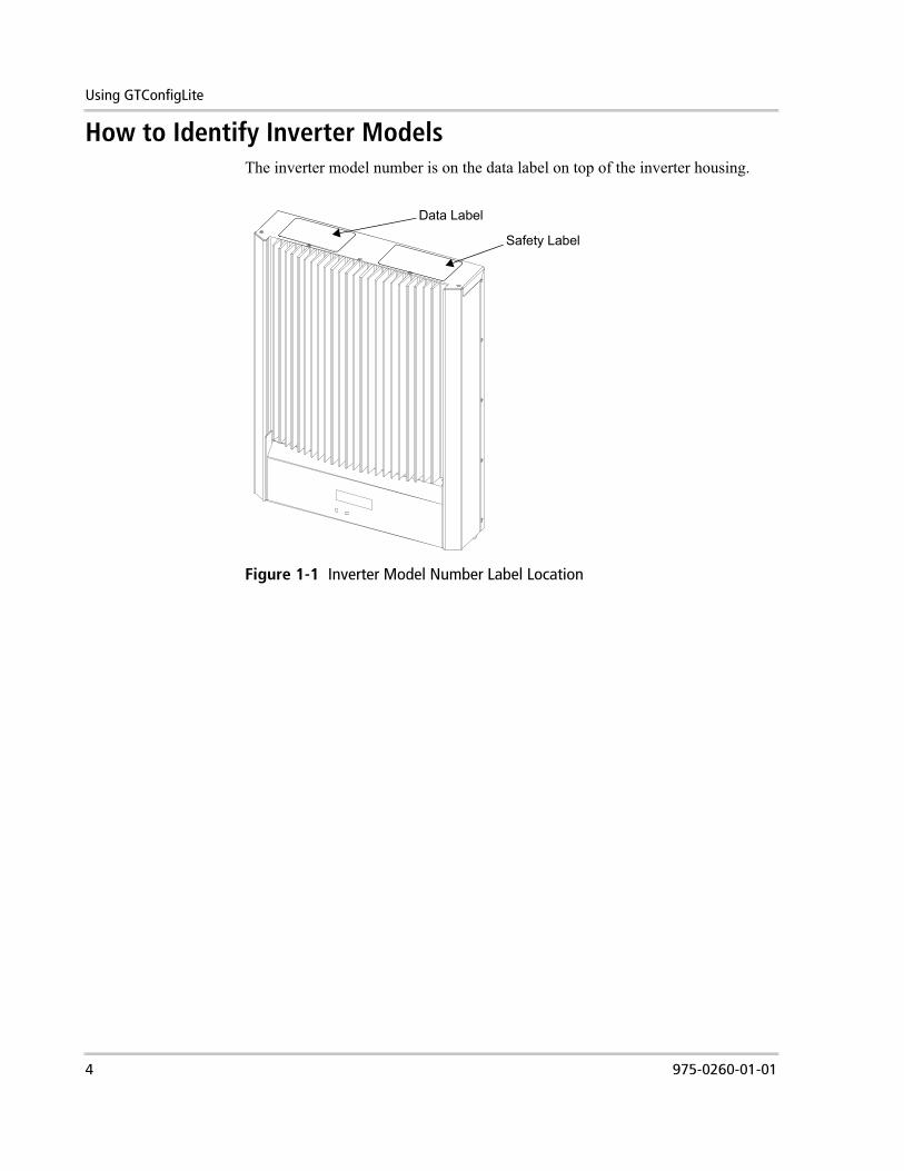
How to Identify Inverter ModelsThe inverter model number is on the data label on top of the inverter housing.
Figure 1-1 Inverter Model Number Label Location
Safety Label
Data Label
4 975-0260-01-01

Installing GTConfigLite
Installing GTConfigLite
System Requirements
The following items are required to operate GTConfigLite:• GTConfigLite software• A PC running Microsoft Windows (XP is recommended).
The PC should have a 9-pin serial port (or a USB port with USB-to-serial dongle).
• A short straight through 9-pin serial cable to interface the PC Computer to the System Control Board
The software has been fully tested on Windows XP Operating System and partially tested on Windows VISTA.
Installing the Software
To install GTConfigLite:1. Extract the contents of the GTConfigLite WinZip file.2. Double-click setup.exe and follow the Setup Wizard.
The Setup Wizard installs the program GTConfigLite.exe into the default folder.
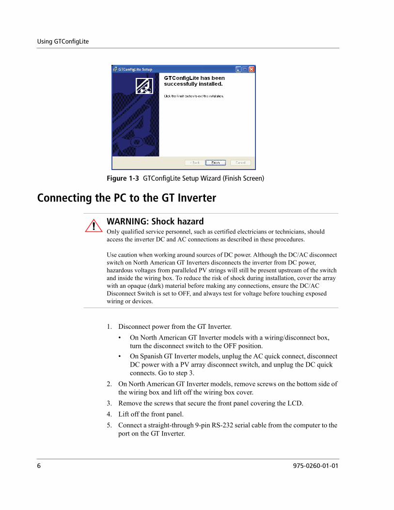
After installation is complete, the screen shown in Figure 1-3 is displayed.
Figure 1-2 GTConfigLite Setup Wizard (Destination Folder)
975-0260-01-01 5
Using GTConfigLite
Connecting the PC to the GT Inverter
1. Disconnect power from the GT Inverter.• On North American GT Inverter models with a wiring/disconnect box,
turn the disconnect switch to the OFF position.• On Spanish GT Inverter models, unplug the AC quick connect, disconnect
DC power with a PV array disconnect switch, and unplug the DC quick connects. Go to step 3.
2. On North American GT Inverter models, remove screws on the bottom side of the wiring box and lift off the wiring box cover.
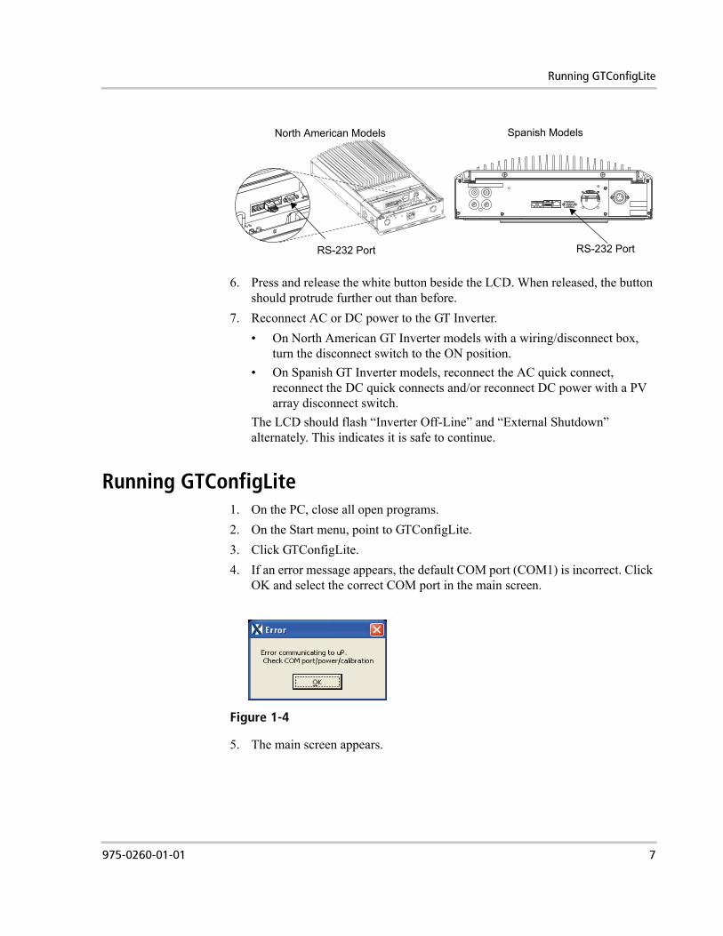
3. Remove the screws that secure the front panel covering the LCD.4. Lift off the front panel.5. Connect a straight-through 9-pin RS-232 serial cable from the computer to the
port on the GT Inverter.
Figure 1-3 GTConfigLite Setup Wizard (Finish Screen)
WARNING: Shock hazardOnly qualified service personnel, such as certified electricians or technicians, should access the inverter DC and AC connections as described in these procedures.
Use caution when working around sources of DC power. Although the DC/AC disconnect switch on North American GT Inverters disconnects the inverter from DC power, hazardous voltages from paralleled PV strings will still be present upstream of the switch and inside the wiring box. To reduce the risk of shock during installation, cover the array with an opaque (dark) material before making any connections, ensure the DC/AC Disconnect Switch is set to OFF, and always test for voltage before touching exposed wiring or devices.
6 975-0260-01-01
Running GTConfigLite
6. Press and release the white button beside the LCD. When released, the button should protrude further out than before.
7. Reconnect AC or DC power to the GT Inverter.• On North American GT Inverter models with a wiring/disconnect box,
turn the disconnect switch to the ON position.• On Spanish GT Inverter models, reconnect the AC quick connect,
reconnect the DC quick connects and/or reconnect DC power with a PV array disconnect switch.
The LCD should flash “Inverter Off-Line” and “External Shutdown” alternately. This indicates it is safe to continue.
Running GTConfigLite1. On the PC, close all open programs.2. On the Start menu, point to GTConfigLite.3. Click GTConfigLite.4. If an error message appears, the default COM port (COM1) is incorrect. Click
OK and select the correct COM port in the main screen.
5. The main screen appears.
RS-232 Port
North American Models
RS-232 Port
Spanish Models
Figure 1-4
975-0260-01-01 7
Using GTConfigLite
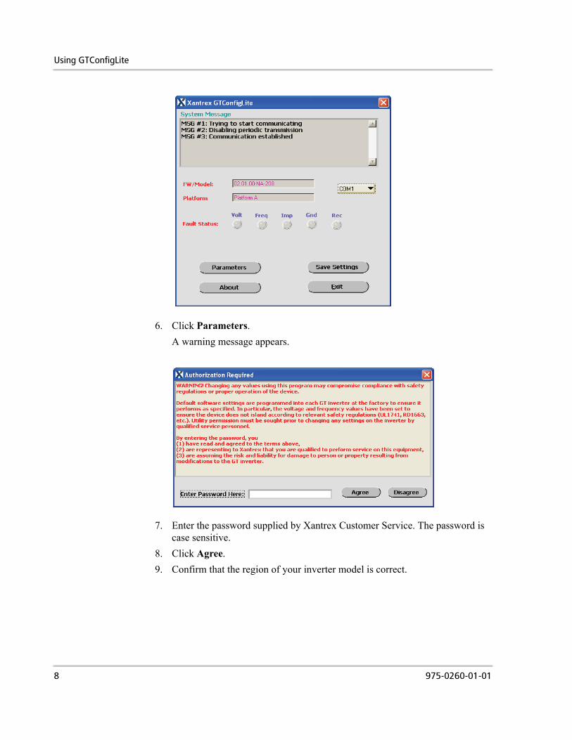
6. Click Parameters.A warning message appears.
7. Enter the password supplied by Xantrex Customer Service. The password is case sensitive.
8. Click Agree.9. Confirm that the region of your inverter model is correct.
8 975-0260-01-01

Changing Parameters
If the region is correct, click Yes. The GT Parameters window opens.
Changing ParametersTo change parameters:1. In the GT Parameters window, double click the desired cell in the Write
column.2. Enter a new value.
You can only enter values within the minimum and maximum range of the parameter.
3. If you want to change another parameter, go to step 1.4. Click Program.5. Verify that the new values appear in the Read column.6. To return to the main screen, click Exit.If you make an error while changing parameters, you can restore the default settings at any time.
Figure 1-5 GT Parameters Window
975-0260-01-01 9
Using GTConfigLite
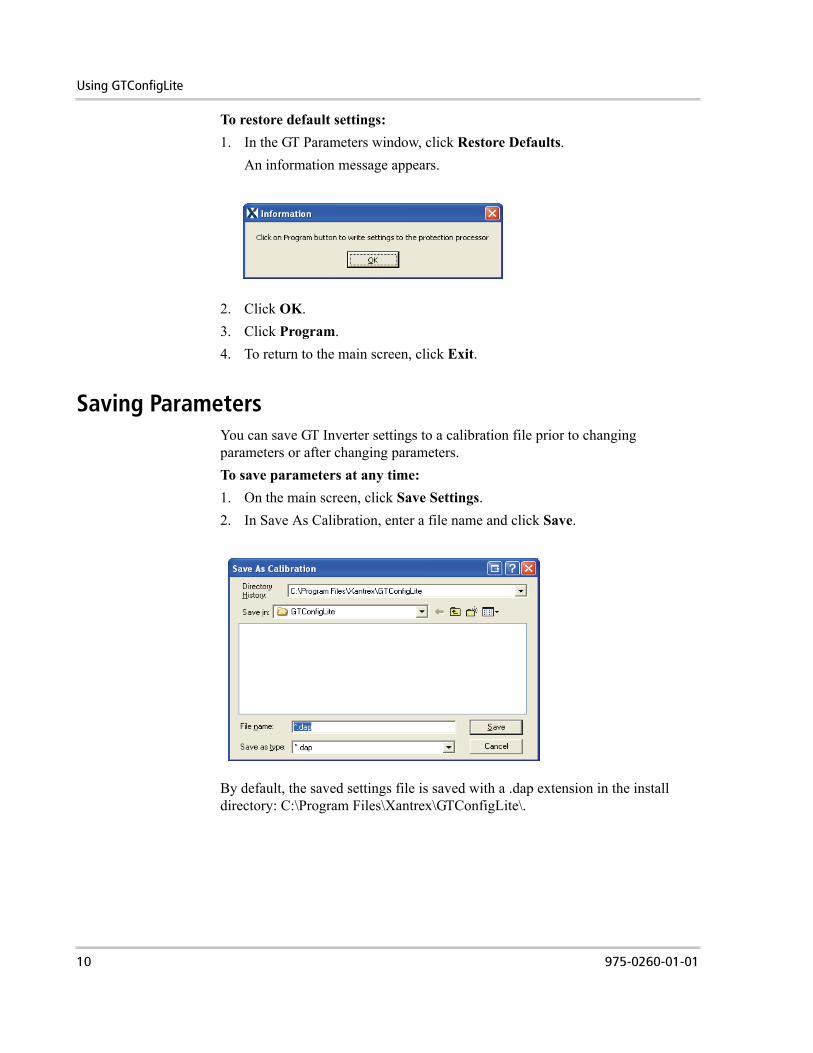
To restore default settings:1. In the GT Parameters window, click Restore Defaults.
An information message appears.
2. Click OK.3. Click Program.4. To return to the main screen, click Exit.
Saving ParametersYou can save GT Inverter settings to a calibration file prior to changing parameters or after changing parameters.To save parameters at any time:1. On the main screen, click Save Settings.2. In Save As Calibration, enter a file name and click Save.
By default, the saved settings file is saved with a .dap extension in the install directory: C:\Program Files\Xantrex\GTConfigLite\.
10 975-0260-01-01
Restoring Operation
Restoring OperationAfter the new settings have been entered:1. Disconnect power from the inverter again. (For model-specific procedures,
see “Connecting the PC to the GT Inverter” on page 1–6.)2. Press the switch beside the LCD in so that it stays in.3. Remove the RS-232 cable from the GT Inverter.4. Replace all panels and covers you removed earlier.5. Restart the GT Inverter.
• To restart North American models with a wiring/disconnect box, turn the disconnect switch to the ON position for 10 seconds, turn the switch OFF, then turn it ON again.
• For models without a disconnect switch, reconnect all AC and DC quick connects (carefully observing correct polarity), and switch on DC and AC power.
6. When the inverter restarts, you can verify changed voltage or frequency parameters by looking at the third startup screen. For more information on startup screens, see Chapter 5 in the GT Inverter Owner's Manual.
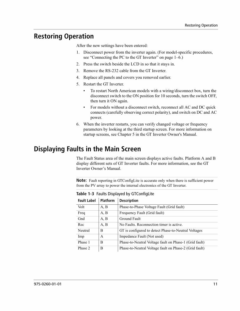
Displaying Faults in the Main ScreenThe Fault Status area of the main screen displays active faults. Platform A and B display different sets of GT Inverter faults. For more information, see the GT Inverter Owner’s Manual.
Note: Fault reporting in GTConfigLite is accurate only when there is sufficient power from the PV array to power the internal electronics of the GT Inverter.
Table 1-3 Faults Displayed by GTConfigLite
Fault Label Platform Description
Volt A, B Phase-to-Phase Voltage Fault (Grid fault)Freq A, B Frequency Fault (Grid fault)Gnd A, B Ground FaultRec A, B No Faults. Reconnection timer is active.Neutral B GT is configured to detect Phase-to-Neutral VoltagesImp A Impedance Fault (Not used)Phase 1 B Phase-to-Neutral Voltage fault on Phase-1 (Grid fault)Phase 2 B Phase-to-Neutral Voltage fault on Phase-2 (Grid fault)
975-0260-01-01 11
Using GTConfigLite
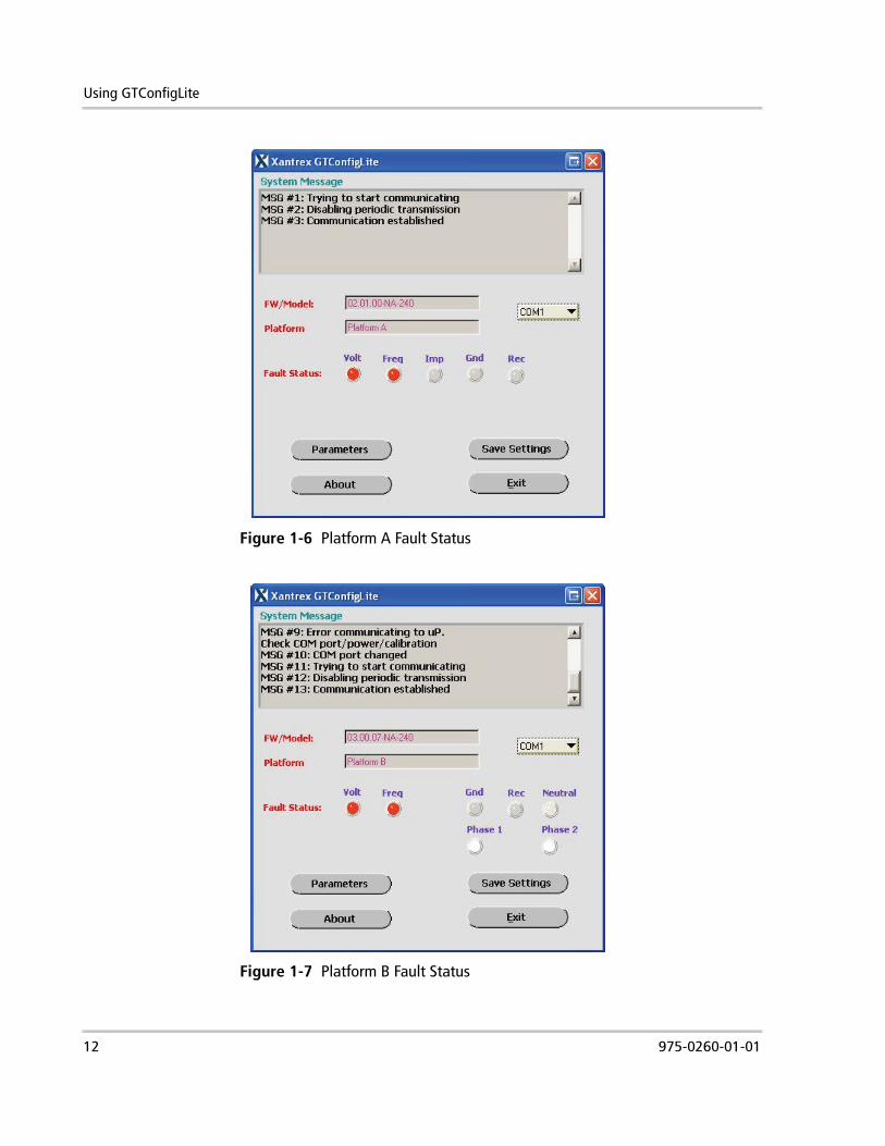
Figure 1-6 Platform A Fault Status
Figure 1-7 Platform B Fault Status
12 975-0260-01-01
Changing Parameters: Examples
Changing Parameters: ExamplesIf you find that the inverter is frequently disconnecting from the grid due to a utility fault—which the inverter displays as an AC Voltage Fault or a Frequency Fault flashing alternately with “Inverter Offline” on the LCD—you may have to adjust the default GT parameters to meet the specifications of your local power utility.
AC Voltage Faults
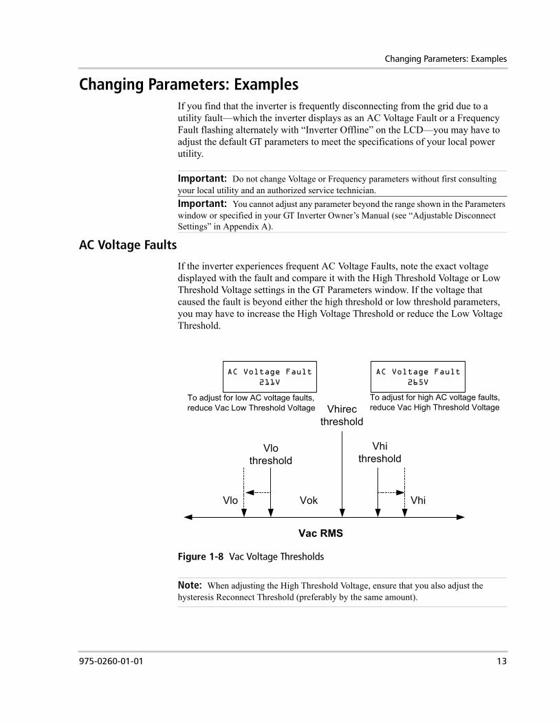
If the inverter experiences frequent AC Voltage Faults, note the exact voltage displayed with the fault and compare it with the High Threshold Voltage or Low Threshold Voltage settings in the GT Parameters window. If the voltage that caused the fault is beyond either the high threshold or low threshold parameters, you may have to increase the High Voltage Threshold or reduce the Low Voltage Threshold.
Important: Do not change Voltage or Frequency parameters without first consulting your local utility and an authorized service technician.Important: You cannot adjust any parameter beyond the range shown in the Parameters window or specified in your GT Inverter Owner’s Manual (see “Adjustable Disconnect Settings” in Appendix A).
Figure 1-8 Vac Voltage Thresholds
Note: When adjusting the High Threshold Voltage, ensure that you also adjust the hysteresis Reconnect Threshold (preferably by the same amount).
Vhirecthreshold
Vhithreshold
VhiVlo
Vlothreshold
Vok
AC Voltage Fault211V
AC Voltage Fault265V
Vac RMS
To adjust for low AC voltage faults, reduce Vac Low Threshold Voltage
To adjust for high AC voltage faults, reduce Vac High Threshold Voltage
975-0260-01-01 13
Using GTConfigLite
Frequency Faults
If the inverter often experiences Frequency Faults, note the exact frequency displayed with the fault and compare it with the Frequency High Threshold or Frequency Low Threshold settings in the GT Parameters window. If it is beyond either of those parameters, you may have to increase the Frequency High Threshold or reduce the Frequency Low Threshold.
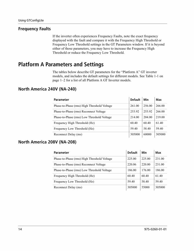
Platform A Parameters and SettingsThe tables below describe GT parameters for the “Platform A” GT inverter models, and includes the default settings for different models. See Table 1-1 on page 1–2 for a list of all Platform A GT Inverter models.
North America 240V (NA-240)
North America 208V (NA-208)
Parameter Default Min Max
Phase-to-Phase (rms) High Threshold Voltage 261.00 256.00 266.00
Phase-to-Phase (rms) Reconnect Voltage 253.92 253.92 266.00
Phase-to-Phase (rms) Low Threshold Voltage 214.00 204.00 219.00
Frequency High Threshold (Hz) 60.40 60.40 61.40
Frequency Low Threshold (Hz) 59.40 58.40 59.40
Reconnect Delay (ms) 305000 60000 305000
Parameter Default Min Max
Phase-to-Phase (rms) High Threshold Voltage 225.00 225.00 231.00
Phase-to-Phase (rms) Reconnect Voltage 220.06 220.00 231.00
Phase-to-Phase (rms) Low Threshold Voltage 186.00 176.00 186.00
Frequency High Threshold (Hz) 60.40 60.40 61.40
Frequency Low Threshold (Hz) 59.40 58.40 59.40
Reconnect Delay (ms) 305000 55000 305000
14 975-0260-01-01
Platform B Parameters and Settings
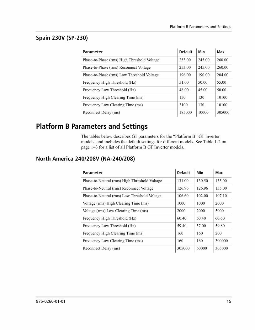
Spain 230V (SP-230)
Platform B Parameters and SettingsThe tables below describes GT parameters for the “Platform B” GT inverter models, and includes the default settings for different models. See Table 1-2 on page 1–3 for a list of all Platform B GT Inverter models.
North America 240/208V (NA-240/208)
Parameter Default Min Max
Phase-to-Phase (rms) High Threshold Voltage 253.00 245.00 260.00
Phase-to-Phase (rms) Reconnect Voltage 253.00 245.00 260.00
Phase-to-Phase (rms) Low Threshold Voltage 196.00 190.00 204.00
Frequency High Threshold (Hz) 51.00 50.00 55.00
Frequency Low Threshold (Hz) 48.00 45.00 50.00
Frequency High Clearing Time (ms) 150 130 10100
Frequency Low Clearing Time (ms) 3100 130 10100
Reconnect Delay (ms) 185000 10000 305000
Parameter Default Min Max
Phase-to-Neutral (rms) High Threshold Voltage 131.00 130.50 135.00
Phase-to-Neutral (rms) Reconnect Voltage 126.96 126.96 135.00
Phase-to-Neutral (rms) Low Threshold Voltage 106.60 102.00 107.10
Voltage (rms) High Clearing Time (ms) 1000 1000 2000
Voltage (rms) Low Clearing Time (ms) 2000 2000 5000
Frequency High Threshold (Hz) 60.40 60.40 60.60
Frequency Low Threshold (Hz) 59.40 57.00 59.80
Frequency High Clearing Time (ms) 160 160 200
Frequency Low Clearing Time (ms) 160 160 300000
Reconnect Delay (ms) 305000 60000 305000
975-0260-01-01 15
Using GTConfigLite
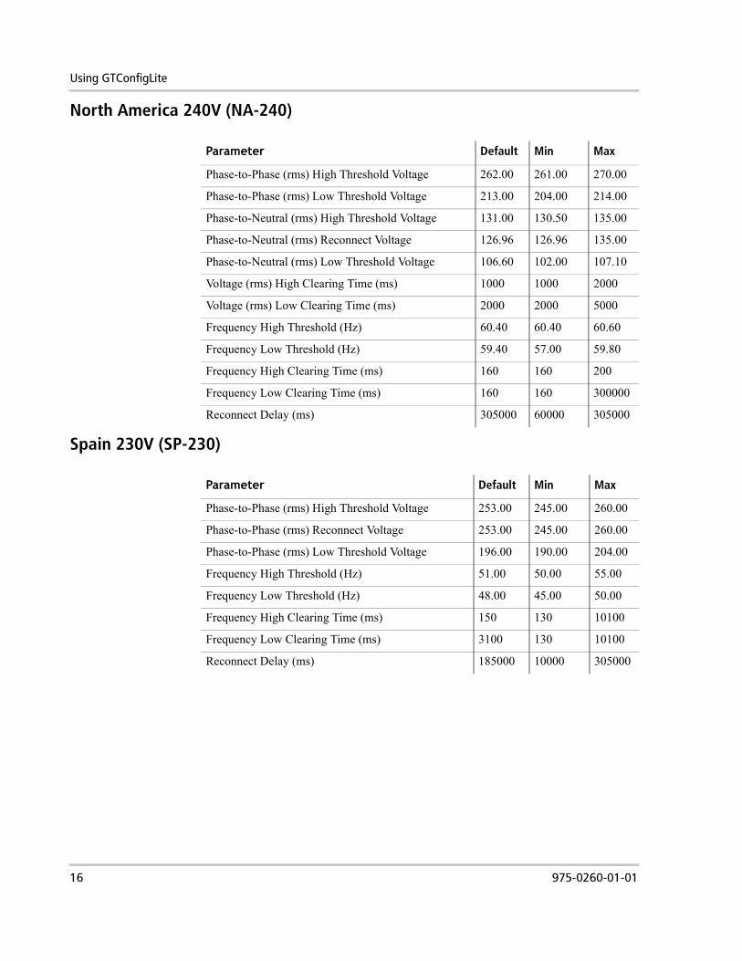
North America 240V (NA-240)
Spain 230V (SP-230)
Parameter Default Min Max
Phase-to-Phase (rms) High Threshold Voltage 262.00 261.00 270.00
Phase-to-Phase (rms) Low Threshold Voltage 213.00 204.00 214.00
Phase-to-Neutral (rms) High Threshold Voltage 131.00 130.50 135.00
Phase-to-Neutral (rms) Reconnect Voltage 126.96 126.96 135.00
Phase-to-Neutral (rms) Low Threshold Voltage 106.60 102.00 107.10
Voltage (rms) High Clearing Time (ms) 1000 1000 2000
Voltage (rms) Low Clearing Time (ms) 2000 2000 5000
Frequency High Threshold (Hz) 60.40 60.40 60.60
Frequency Low Threshold (Hz) 59.40 57.00 59.80
Frequency High Clearing Time (ms) 160 160 200
Frequency Low Clearing Time (ms) 160 160 300000
Reconnect Delay (ms) 305000 60000 305000
Parameter Default Min Max
Phase-to-Phase (rms) High Threshold Voltage 253.00 245.00 260.00
Phase-to-Phase (rms) Reconnect Voltage 253.00 245.00 260.00
Phase-to-Phase (rms) Low Threshold Voltage 196.00 190.00 204.00
Frequency High Threshold (Hz) 51.00 50.00 55.00
Frequency Low Threshold (Hz) 48.00 45.00 50.00
Frequency High Clearing Time (ms) 150 130 10100
Frequency Low Clearing Time (ms) 3100 130 10100
Reconnect Delay (ms) 185000 10000 305000
16 975-0260-01-01
Parameter Reference Guide
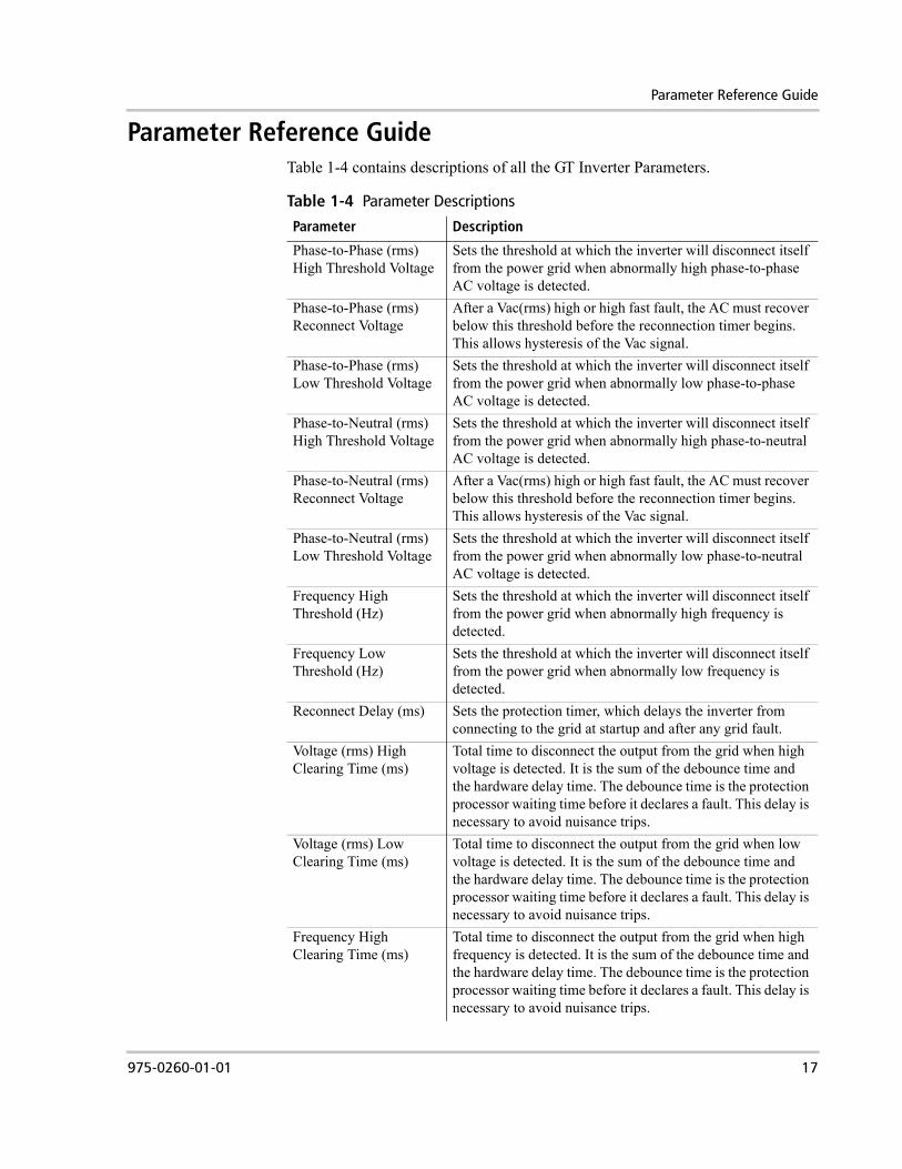
Parameter Reference GuideTable 1-4 contains descriptions of all the GT Inverter Parameters.
Table 1-4 Parameter Descriptions
Parameter Description
Phase-to-Phase (rms) High Threshold Voltage
Sets the threshold at which the inverter will disconnect itself from the power grid when abnormally high phase-to-phase AC voltage is detected.
Phase-to-Phase (rms) Reconnect Voltage
After a Vac(rms) high or high fast fault, the AC must recover below this threshold before the reconnection timer begins. This allows hysteresis of the Vac signal.
Phase-to-Phase (rms) Low Threshold Voltage
Sets the threshold at which the inverter will disconnect itself from the power grid when abnormally low phase-to-phase AC voltage is detected.
Phase-to-Neutral (rms) High Threshold Voltage
Sets the threshold at which the inverter will disconnect itself from the power grid when abnormally high phase-to-neutral AC voltage is detected.
Phase-to-Neutral (rms) Reconnect Voltage
After a Vac(rms) high or high fast fault, the AC must recover below this threshold before the reconnection timer begins. This allows hysteresis of the Vac signal.
Phase-to-Neutral (rms) Low Threshold Voltage
Sets the threshold at which the inverter will disconnect itself from the power grid when abnormally low phase-to-neutral AC voltage is detected.
Frequency High Threshold (Hz)
Sets the threshold at which the inverter will disconnect itself from the power grid when abnormally high frequency is detected.
Frequency Low Threshold (Hz)
Sets the threshold at which the inverter will disconnect itself from the power grid when abnormally low frequency is detected.
Reconnect Delay (ms) Sets the protection timer, which delays the inverter from connecting to the grid at startup and after any grid fault.
Voltage (rms) High Clearing Time (ms)
Total time to disconnect the output from the grid when high voltage is detected. It is the sum of the debounce time and the hardware delay time. The debounce time is the protection processor waiting time before it declares a fault. This delay is necessary to avoid nuisance trips.
Voltage (rms) Low Clearing Time (ms)
Total time to disconnect the output from the grid when low voltage is detected. It is the sum of the debounce time and the hardware delay time. The debounce time is the protection processor waiting time before it declares a fault. This delay is necessary to avoid nuisance trips.
Frequency High Clearing Time (ms)
Total time to disconnect the output from the grid when high frequency is detected. It is the sum of the debounce time and the hardware delay time. The debounce time is the protection processor waiting time before it declares a fault. This delay is necessary to avoid nuisance trips.
975-0260-01-01 17
Using GTConfigLite
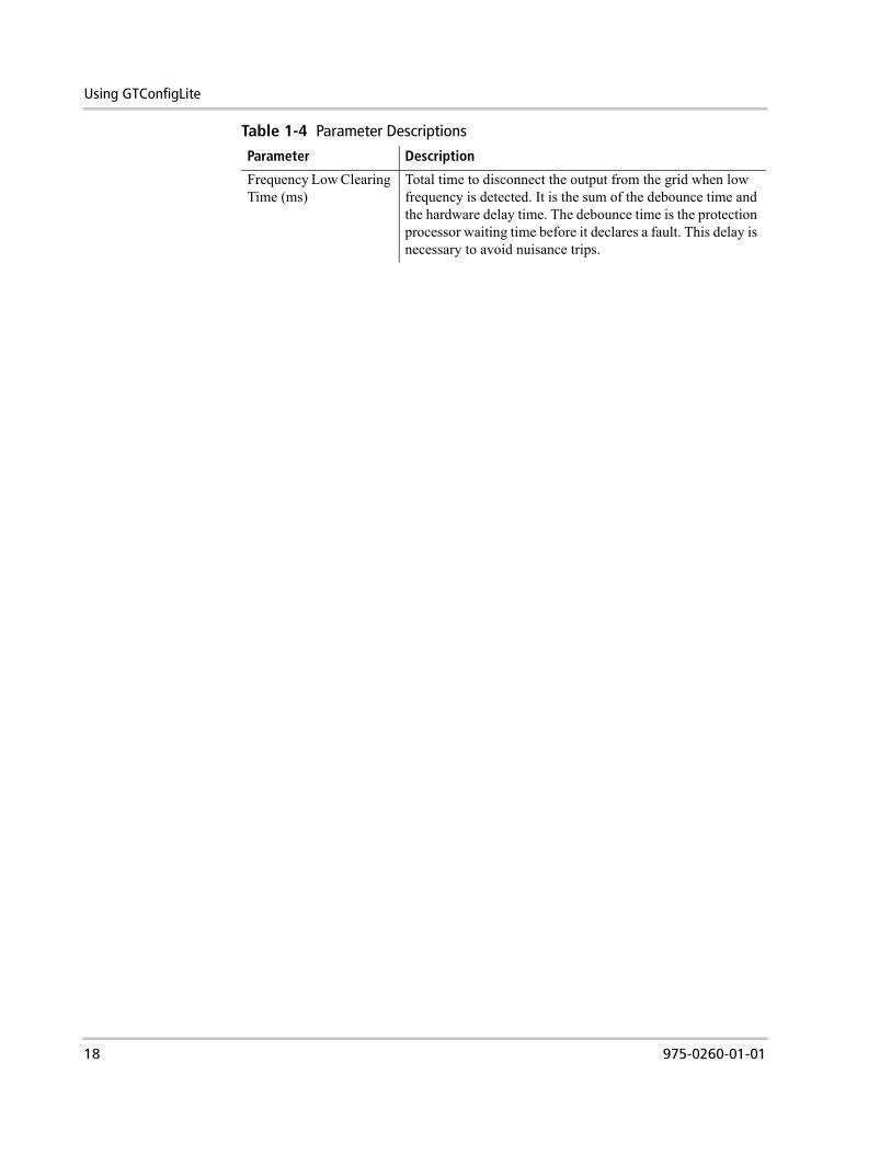
Frequency Low Clearing Time (ms)
Total time to disconnect the output from the grid when low frequency is detected. It is the sum of the debounce time and the hardware delay time. The debounce time is the protection processor waiting time before it declares a fault. This delay is necessary to avoid nuisance trips.
Table 1-4 Parameter Descriptions
Parameter Description
18 975-0260-01-01

Xantrex Technology Inc.
1 800 670 0707 Tel toll free NA1 360 925 5097 Tel direct(+34) 93 470 5330 (Europe)1 360 925 5143 Fax direct(+34) 93 473 6093 (Europe)[email protected]@xantrex.com (Europe)www.xantrex.com
975-0260-01-01