Embed Size (px)
Citation preview

GT SoftGOT Version5
Operating ManualOperating Manual
MITSUBISHI Graphic Operation Terminal
GT SoftGOT Version5
MELSOFT SW5D5C-GTWORKS-EIntegrated Software
When exported from Japan, this manual does not require application to theMinistry of International Trade and Industry for service transaction permission.
Specifications subject to change without notice.
HEAD OFFICE : MITSUBISHI DENKI BLDG MARUNOUCHI TOKYO 100-8310 TELEX : J24532 CABLE MELCO TOKYONAGOYA WORKS : 1-14 , YADA-MINAMI 5 , HIGASHI-KU, NAGOYA , JAPAN
SW5-GTSIM-O-E
13JU09
SH(NA)-080156-A(0102)MEE
MODEL
MODELCODE
O
GT
So
ftGO
T V
ers
ion
5 O
pe
ratin
g M
an
ua
l

A - 1 A - 1
• SAFETY PRECAUTIONS •(Always read these instructions before using this equipment.)
Before using this product, please read this manual and the relevant manuals introduced in this manual
carefully and pay full attention to safety to handle the product correctly.
The instructions given in this manual are concerned with this product. For the safety instructions of the
programmable controller system, please read the CPU module user's manual.
In this manual, the safety instructions are ranked as "DANGER" and "CAUTION".
! DANGER
CAUTION!
Indicates that incorrect handling may cause hazardous conditions,resulting in death or severe injury.
Indicates that incorrect handling may cause hazardous conditions, resulting in medium or slight personal injury or physical damage.
Note that the ! CAUTION level may lead to a serious consequence according to the circumstances.
Always follow the instructions of both levels because they are important to personal safety.
Please save this manual to make it accessible when required and always forward it to the end user.
[Test Operation Instructions]
! DANGER
• Before performing test operation (bit device on/off, word device's present value changing,
timer/counter's set value and present value changing, buffer memory's present value changing)
for a user-created monitor screen, system monitoring, special module monitoring or ladder
monitoring, read the manual carefully to fully understand how to operate the equipment.
During test operation, never change the data of the devices which are used to perform
significant operation for the system.
False output or malfunction can cause an accident.

A - 2 A - 2
Precautions for using this software (important)
1. Memory of the personal computer usedProcessing may be terminated by Windows® on some personal computer models having main memory ofnot more than 64M bytes. Therefore, use them after increasing the main memory to 64M bytes or more.
2. Free space on the hard diskWhile this software is running, free space of at least 50M byte is required on the hard disk.Since free space of 50M byte is required by Windows® as the swap area, Windows® may forcibly terminatethe program if that free space is used up while the this software is running. Produce a sufficient amount offree space on the hard disk before using the this software.
3. Instructions for displaying any line other than a continuous line (such as a dotted line) in boldface typeWhen any line other than a continuous line is drawn in boldface type, the personal computer screen may notdisplay the line type properly. However, it is displayed properly on the GOT and there are no problems in data.

A - 3 A - 3
REVISIONS* The manual number is given on the bottom left of the back cover.
Print Date * Manual Number RevisionFeb., 2001 SH (NA)-080156-A First editionMay, 2001 SH (NA)-080156-B Partial corrections
Section 2.3.1, Section 2.3.2, Section 5.3.1 Partial additions Section 5.3.3
Jun., 2001 SH (NA)-080156-C Partial corrections Section 2.1.1, Section 2.1.2, Section 2.2, Section 2.3.1, Section 2.3.2,Section 2.4.1, Section 3.1, Section 3.2, Section 3.3.2, Section 5.1,Section 5.3.1, Section 5.3.2, Section 5.3.3 Partial additions Section 5.2, Section 7.1 Additions Section 2.5.3, Appendix 1
Aug., 2001 SH (NA)-080156-D Partial corrections Section 5.1, Section 5.6, Section 5.7, Section 5.8, Section 5.9, Section5.11 Partial additions Section 2.1, Section 2.2, Section 2.3, Section 2.4, Section 2.5, Section3.1, Section 3.2, Section 4.1, Section 4.2, Section 5.5, Appendix 1 Additions
Section 5.4, Section 6.5May, 2002 SH (NA)-080156-E Partial corrections
Section 2.1.2, Section 3.1, Section 3.2, Section 5.5, Section 5.6,Section 5.7, Section 5.9, Section 6.4.4 Partial additions Section 2.3.1, Section 2.3.2, Section 4.2, Section 5.3, Section 5.10,Section 5.11, Section 6.3, Section 6.4.3, Section 6.4.5, Section 6.5,Section 7.3, Appendix 1 Additions
Section 6.6, Section 6.7Oct., 2002 SH (NA)-080156-F Partial corrections
Section 2.5.3, Section 5.3.1, Section 5.3.2, Section 5.3.3, Section 5.5,Section 5.5.1 Partial additions Section 2.2, Section 3.2, Section 3.3.2, Appendix 1 Additions
Section 2.3.4, Section 2.4.4, Section 2.5.4
Jun., 2004 SH (NA)-080156-G Partial corrections Manuals MODEL CODE change Changed from 13JU12 to 1DM193
Japanese Manual Version SH-080131-I
This manual confers no industrial property rights or any rights of any other kind, nor does it confer any patentlicenses. Mitsubishi Electric Corporation cannot be held responsible for any problems involving industrial propertyrights which may occur as a result of using the contents noted in this manual.
2001 MITSUBISHI ELECTRIC CORPORATION

A - 4 A - 4
INTRODUCTION
Thank you for choosing the Mitsubishi Graphic Operation Terminal.Before using the equipment, please read this manual carefully to use the equipment to its optimum.
CONTENTS
About manuals ................................................................................................................................................A- 7
Abbreviations and generic terms in this manual ............................................................................................A- 8
1. OVERVIEW 1- 1 to 1- 2
1.1 Features .................................................................................................................................................... 1- 1
2. SYSTEM CONFIGURATION 2- 1 to 2-15
2.1 System Configuration at Installation of GT SoftGOT............................................................................... 2- 1
2.1.1 System configuration ........................................................................................................................................2- 1
2.1.2 Operation environment.....................................................................................................................................2- 1
2.2 System Configuration for GT SoftGOT Execution ................................................................................... 2- 2
2.3 Equipment that can Be Used Together with GT SoftGOT ...................................................................... 2- 4
2.3.1 PLC CPUs that can be connected ..................................................................................................................2- 4
2.3.2 Ethernet units and Ethernet boards/cards that can be used........................................................................2- 5
2.3.3 Computer link units and serial communication units that can be used.......................................................2- 5
2.3.4 Network units and network boards that can be connected ..........................................................................2- 6
2.4 About the cable ......................................................................................................................................... 2- 7
2.4.1 Cables used for connecting directly to CPUs.................................................................................................2- 7
2.4.2 Cables used for connecting via Ethernet........................................................................................................2- 7
2.4.3 Cable used for connecting Computer link connection ..................................................................................2- 8
2.4.4 Cables used for connecting MELSECNET connection ...............................................................................2-12
2.5 Access range for monitoring.................................................................................................................... 2-13
2.5.1 Access range that can be monitored when CPU direct connection/computer link connection...............2-13
2.5.2 Access range that can be monitored when connecting via Ethernet .........................................................2-13
2.5.3 Access range that can be monitored for Q bus connection (only when PC CPU module is used)........2-14
2.5.4 Access ranges that can be monitored for MELSECNET connection.........................................................2-15
3. SPECIFICATIONS 3- 1 to 3- 5
3.1 Specifications of the GT SoftGOT ............................................................................................................ 3- 1
3.2 Functions that cannot be Used................................................................................................................. 3- 2
3.3 Restrictions on and Instructions for use of GT SoftGOT ......................................................................... 3- 4
3.3.1 Restrictions on and instructions for GT SoftGOT..........................................................................................3- 4
3.3.2 Restrictions on and instructions for PLC CPU connection ...........................................................................3- 5
4. SCREEN CONFIGURATION OF GT SOFTGOT 4- 1 to 4- 4
4.1 Screen Configuration and Various Tools of GT SoftGOT ....................................................................... 4- 1
4.2 Menu Configuration................................................................................................................................... 4- 3

A - 5 A - 5
5. GT SOFTGOT OPERATING METHOD 5- 1 to 5-29
5.1 General Procedure for Monitoring with GT SoftGOT............................................................................... 5- 1
5.2 How to Use the License Key/License Key FD ......................................................................................... 5- 2
5.3 How to set up Ethernet connection .......................................................................................................... 5- 6
5.3.1 When using E71................................................................................................................................................5- 6
5.3.2 When using QE71............................................................................................................................................5-11
5.3.3 When using Q Series Compatible E71..........................................................................................................5-14
5.3.4 How to Set Devices Using GT Designer .......................................................................................................5-17
5.4 How to set up the Computer link connection .......................................................................................... 5-18
5.4.1 When using A Series .......................................................................................................................................5-18
5.4.2 When using QnA Series..................................................................................................................................5-19
5.4.3 When using Q Series.......................................................................................................................................5-20
5.4.4 Transmission specifications ............................................................................................................................5-20
5.5 Option Setting........................................................................................................................................... 5-21
5.5.1 Option Setting Dialog Box ...............................................................................................................................5-22
5.6 Execution of monitor ................................................................................................................................ 5-24
5.7 Opening the Project ................................................................................................................................. 5-25
5.7.1 Description of the monitor data reading dialog box......................................................................................5-27
5.8 Operation at Monitoring ........................................................................................................................... 5-28
5.9 Stopping Monitoring ................................................................................................................................. 5-28
5.10 Exiting from GT SoftGOT....................................................................................................................... 5-28
5.11 Automatic Startup................................................................................................................................... 5-29
6. FUNCTIONS OF GT SOFTGOT 6- 1 to 6-20
6.1 Snap Shot Function .................................................................................................................................. 6- 1
6.1.1 Operating procedure.........................................................................................................................................6- 1
6.2 Print Function ............................................................................................................................................ 6- 2
6.2.1 Operating procedure.........................................................................................................................................6- 2
6.2.2 Print preview ......................................................................................................................................................6- 2
6.2.3 Page setup.........................................................................................................................................................6- 2
6.3 Data Reference Function.......................................................................................................................... 6- 3
6.4 Mail Function ............................................................................................................................................. 6- 4
6.4.1 Mail function overview.......................................................................................................................................6- 4
6.4.2 Operation flow when using the mail function..................................................................................................6- 5
6.4.3 How to set up the mail function........................................................................................................................6- 6
6.4.4 Sending e-mail..................................................................................................................................................6-11
6.4.5 Mail history ........................................................................................................................................................6-13
6.5 Keyboard input function ........................................................................................................................... 6-14
6.5.1 Keyboard Input Enabling/Disabling Procedure.............................................................................................6-14
6.5.2 When operating the numerical input function or the ASCII input function from the keyboard of a PC
...........................................................................................................................................................................6-14
6.5.3 How to Use the Function Keys .......................................................................................................................6-15
6.5.4 Precautions for Use..........................................................................................................................................6-15

A - 6 A - 6
6.6 Full Screen Mode Function...................................................................................................................... 6-16
6.6.1 Full screen mode function types.....................................................................................................................6-16
6.6.2 Setting method..................................................................................................................................................6-18
6.6.3 Precautions for use ..........................................................................................................................................6-19
6.7 Disable/Enable of Popupmenu................................................................................................................ 6-20
6.7.1 Setting method..................................................................................................................................................6-20
6.7.2 Precautions for use ..........................................................................................................................................6-20
7. TROUBLESHOOTING 7- 1 to 7- 4
7.1 Error messages......................................................................................................................................... 7- 1
7.2 Troubleshooting Related to the License Key ........................................................................................... 7- 3
7.3 Troubleshooting Related to Mail Transmission........................................................................................ 7- 4
APPENDIX App- 1 to App- 3
Appendix1 List of Functions Added to Update GT SoftGOT.....................................................................App- 1
INDEX Index- 1 to Index- 2

A - 7 A - 7
Manuals
The following manuals are relevant to this product.
Refer to the following list and order the required manuals.
• Detailed manual
Manual name Manual number (Model code)
A985GOT/A975GOT/A970GOT/A960GOT User’s ManualExplains the specifications, general system configuration, component devices, part names, optionunit loading methods, installation and wiring methods, maintenance and inspection methods, anderror codes of A985GOT/A975GOT/A970GOT/A960GOT unit.
(Available as option)
SH-4005(1DM099)
A950GOT/A951GOT/A953GOT/A956GOT User’s ManualExplains the specifications, general system configuration, component devices, part names, optionunit loading methods, installation and wiring methods, maintenance and inspection methods, anderror codes of A950GOT/A951GOT/A953GOT/A956GOT unit.
(Available as option)
SH-080018(1DM103)
• Relevant Manual
For relevant manual, refer to the PDF manual stored within the drawing software.

A - 8 A - 8
Abbreviations and generic terms in this manual
Abbreviations, generic terms and special terms used in this manual are described as
follows:
Abbreviations, generic termsand special terms
Description
A985GOT-V Generic term of A985GOT-TBA-V and A985GOT-TBD-VA985GOT Generic term of A985GOT-TBA, A985GOT-TBD and A985GOT-TBA-EU
A975GOT Generic term of A975GOT-TBA-B, A975GOT-TBD-B, A975GOT-TBA, A975GOT-TBD andA975GOT-TBA-EU
A970GOTGeneric term of A970GOT-TBA-B A970GOT-TBD-B, A970GOT-TBA, A970GOT-TBD,A970GOT-SBA, A970GOT-SBD, A970GOT-LBA, A970GOT-LBD, A970GOT-TBA-EU andA970GOT-SBA-EU
A97*GOT Generic term of A975GOT and A970GOTA960GOT Generic term of A960GOT-EBA, A960GOT-EBD and A960GOT-EBA-EUA956WGOT Abbreviation of A956WGOT-TBD
A956GOT Generic term of A956GOT-TBD, A956GOT-SBD, A956GOT-LBD, A956GOT-TBD-M3,A956GOT-SBD-M3 and A956GOT-LBD-M3
A953GOT Generic term of A953GOT-TBD, A953GOT-SBD, A953GOT-LBD, A953GOT-TBD-M3,A953GOT-SBD-M3 and A953GOT-LBD-M3
A951GOT Generic term of A951GOT-TBD, A951GOT-SBD, A951GOT-LBD, A951GOT-TBD-M3,A951GOT-SBD-M3 and A951GOT-LBD-M3
A951GOT-Q Generic term of A951GOT-QTBD, A951GOT-QSBD, A951GOT-QLBD, A951GOT-QTBD-M3,A951GOT-QSBD-M3 and A951GOT-QLBD-M3
A950GOT Generic term of A950GOT-TBD, A950GOT-SBD, A950GOT-LBD, A950GOT-TBD-M3,A950GOT-SBD-M3 and A950GOT-LBD-M3
A950 handy GOT Generic term of A953GOT-SBD-M3-H and A953GOT-LBD-M3-H
A95*GOT Generic term of A956GOT, A953GOT, A951GOT, A951GOT-Q, A950GOT and A950 handyGOT
F940GOT Generic term of F940GOT-SWD-E, F940GOT-LWD-E, ET-940BH(-L) and ET-940PH(-L)F930GOT Abbreviation of F930GOT-BWD-E
F940 handy GOT Generic term of F940GOT-SBD-H, F940GOT-LBD-H, F943GOT-SBD-H, F943GOT-LBD-H,F940GOT-SBD-RH, F940GOT-LBD-RH, F943GOT-SBD-RH and F943GOT-LBD-RH
F940WGOT Abbreviation of F940WGOT-TWDGOT-A900 series Generic term of A985GOT-V, A985GOT, A975GOT, A970GOT, A960GOT and A95*GOT
GOT
GOT-F900 series Generic term of F940GOT, F930GOT, F940 handyGOT and F940WGOTGT Works Version 5 Abbreviation of SW5D5C-GTWORKS-E software package
GT Designer Version 5 Generic term of SW5D5C-GOTR-PACKE software package and SW5D5C-GOTR-PACKEVsoftware package
GT Designer Abbreviation of image creation software GT Designer for GOT900GT Simulator Abbreviation of GT Simulator screen simulator GOT900GT Converter Abbreviation of data conversion software GT Converter for GOT900GT Debugger Abbreviation of debugging software GT DebuggerGT Manager Abbreviation of GT Manager data editing software for GOT900GT SoftGOT Abbreviation of monitoring software GT SoftGOT
Software
GX Developer Generic term of SW D5C-GPPW-E/SW D5F-GPPW-E software packages
QCPU (Q Mode)Generic term of Q00JCPU, Q00CPU, Q01CPU, Q02CPU, Q02HCPU, Q06HCPU,Q12HCPU, Q25HCPU, Q12PHCPU and Q25PHCPU CPU units
QCPU (A Mode) Generic term of Q02CPU-A, Q02HCPU-A and Q06HCPU-A CPU unitsQCPU Generic term of QCPU (Q Mode) and QCPU (A Mode)QnACPU (Large Type) Generic term of Q2ACPU, Q2ACPU-S1, Q3ACPU, Q4ACPU and Q4ARCPU CPU unitsQnACPU (Small Type) Generic term of Q2ASCPU, Q2ASCPU-S1, Q2ASHCPU and Q2ASHCPU-S1 CPU units
CPU
QnACPU Generic term of QnACPU (Large Type) and QnACPU (Small Type)

A - 9 A - 9
Abbreviations, generic terms and special terms
Description
AnUCPU Generic term of A2UCPU, A2UCPU-S1, A3UCPU and A4UCPU CPU unitsAnACPU Generic term of A2ACPU, A2ACPU-S1 and A3ACPU CPU unitsAnNCPU Generic term of A1NCPU, A2NCPU, A2NCPU-S1 and A3NCPU CPU unitsACPU (Large Type) Generic term of AnUCPU, AnACPU and AnNCPU CPU unitsA2US(H)CPU Generic term of A2USCPU, A2USCPU-S1 and A2USHCPU-S1 CPU unitsAnS(H)CPU Generic term of A1SCPU, A1SHCPU, A2SCPU and A2SHCPU CPU unitsA1SJ(H)CPU Generic term of A1SJCPU-S3 and A1SJHCPU CPU unitsACPU (Small Type) Generic term of A2US(H)CPU, AnS(H)CPU and A1SJ(H)CPU CPU unitsACPU Generic term of ACPU (Large Type), ACPU (Small Type) and A1FXCPU CPU units
FXCPUGeneric term of FX0 series, FX0N series, FX0S series, FX1 series, FX1N series, FX1NC
series, FX1S series, FX2 series, FX2C series, FX2N series, FX2NC series CPU unit
Motion controller CPUGeneric term of A273UCPU, A273UHCPU, A273UHCPU-S3, A171SCPU-S3,A171SHCPUN, A172SHCPUN, A173UHCPU, A173UHCPU-S1 CPU unit
CPU
FA controller Generic term of LM610, LM7600, LM8000 CPU unit
E71Generic term of AJ71E71-S3, A1SJ71E71-B2-S3, A1SJ71E71-B5-S3, AJ71E71N-B2,AJ71E71N-B5T, A1SJ71E71-B2 and A1SJ71E71N-B5T
QE71Generic term of AJ71QE71, A1SJ71QE71-B2, AJ71QE71-B5, A1SJ71QE71-B5,AJ71QE71N-B2, AJ71QE71N-B5T, A1SJ71QE71-B2 and A1SJ71QE71N-B5T
Ethernet unit
Q series-compatible E71 Generic term of QJ71E71, QJ71E71-B2 and QJ71E71-100
Omron PLCGeneric term of C200HS, C200H, C200Hα Series (C200HX, C200HG, C200HE), CQM1,C1000H, C2000H, CV500, CV1000, CV2000, CVM1-CPU11, CVM1-CPU21, CS1, CJ1CPU unit
Yasukawa PLCGeneric term of GL60S, GL60H, GL70H, GL120, GL130, CP-9200SH, CP-9300MS, MP-920,MP-930, MP-940, CP-9200(H) and PROGIC-8 CPU unit
SLC500 SeriesGeneric term of SLC500-20, SLC500-30, SLC500-40, SLC5/01 SLC5/02, SLC5/03,SLC5/04 SLC5/05
MicroLogix1000 SeriesGeneric term of 1761-L10BWA, 1761-L10BWB, 1761-L16AWA, 1761-L16BWA, 1761-L16BWB, 1761-L16BBB, 1761-L32AWA, 1761-L32BWA, 1761-L32BWB, 1761-L32BBB,1761-L32AAA, 1761-L20AWA-5A, 1761-L20BWA-5A, 1761-L20BWB-5A
MicroLogix1500 Series Abbreviation of 1764-LSPAllen-Bradley PLC Generic term of SLC 500 Series, MicroLogix1000 Series, MicroLogix1500 Series
Sharp PLCGeneric term of JW-21CU, JW-22CU, JW-31CUH, JW-32CUH, JW-33CUH, JW-50CUH,JW-70CUH, JW-100CUH CPU unit
PROSEC T Series Generic term of T2(PU224type), T2E, T2N, T3, T3H CPU unitPROSEC V Series Abbreviation of Model3000(S3) CPU unitToshiba PLC Generic term of PROSEC T Series and PROSEC V SeriesSIEMENS PLC Generic term of SIMATIC S7-300 Series and SIMATIC S7-400 Series CPU unit
Large type H seriesGeneric term of H-302(CPU2-03H), H-702(CPU2-07H), H-1002(CPU2-10H), H-2002(CPU2-20H), H-4010(CPU3-40H),.J-300(CPU-03Ha), H-700(CPU-07Ha), H-2000(CPU-20Ha)
H200 to 252 SeriesGeneric term of H-200(CPU-02H, CPE-02H), H-250(CPU21-02H), H-252(CPU22-02H), H-252B(CPU22-02HB), H-252C(CPU22-02HC, CPE22-02HC)
H Series board typeGeneric term of H-20DR, H-28DR, H-40DR, H-64DR, H-20DT, H-28DT, H-40DT, H-64DT,HL-40DR, HL-64DR
EH-150 Series Generic term of EH-CPU104, EH-CPU208, EH-CPU308, EH-CPU316HITACHI PLC(HIDIC H Series)
Generic term of large type H series,H-200 to 252 Series H Series board type, EH-150 Series
Matsushita PLC Abbreviation of FP Series
Other PLC
Matsushita Electric WorksPLC
Generic term of FP0-C16CT, FP0-C32CT, FP1-C24C, FP1-C40C, FP2, FP3, FP5, FP10(S),FP10SH, FP-M(C20TC) and FP-M(C32TC)
Memory abbreviation of memory (flash memory) in the GOTOS Abbreviation of GOT system softwareObject Setting data for dynamic imageLicense key Abbreviation of A9GTSOFT-LKEY-P license key (for DOS/V personal computer)License key FD Abbreviation of SW5D5F-SGLKEY-E (license registration package for PC CPU module)
DOS/V personal computer IBM PC/AT® or its compatible DOS/V personal computerPC CPU module Abbreviation for MELSEC-Q series compatible PC CPU module (CONTEC CO., LTD. make)
Others
Personal Computer Generic term of IBM PC/AT® and compatible DOS/V personal computer
In this manual, the following products are called by new names.Old Name New Name Remarks
GPPW GX Developer Generic term of SW D5C-GPPW-E/SW D5F-GPPW-E software packages

1 - 1 1 - 1
MELSOFT1 OVERVIEW
Chapter 1 OVERVIEW
This manual explains the system configuration, specifications, screen structure, andoperating method of monitoring software GT SoftGOT (hereinafter abbreviated as GTSoftGOT).GT SoftGOT is used to display lamps, data, and messages on personal computersand panel controllers.
POINTRefer to the GT Works Version 5/GT Designer Version 5 Operating Manual (Start
up Manual) for how to install and start up GT SoftGOT.
1.1 Features
(1) The monitor screen data used in the GOT-A900 Series can beused without changes.Since GT SoftGOT uses the monitor screen data created with GT Designerwithout any modifications, it is possible to use the monitor screen data used inthe GOT-A900 Series without any modifications.GT SoftGOT uses the same screens and operations as GOT. Therefore, therewill be no discomfort or confusion for the operators and maintenance personnel.
GOT GT SoftGOT
There is no need for conversion.The monitor screen data is compatible.
(2) Support for various screen sizesGT SoftGOT supports XGA (1024 x 768 dots, equivalent to type 15) and SXGA(1280 x 1024 dots, equivalent to type 18); it is thus possible to design screens ingreater detail than with conventional software. In addition, it is possible to use thesame screen sizes as A97*GOT (640 x 480 dots, equivalent to type 10) andA985GOT (800 x 600 dots, equivalent to type 12); the screen size can beselected according to the application.
1

1 - 2 1 - 2
MELSOFT1 OVERVIEW
MEMO 1

2 - 1 2 - 1
MELSOFT2 SYSTEM CONFIGURATION
Chapter 2 SYSTEM CONFIGURATION
2.1 System Configuration at Installation of GT SoftGOT
2.1.1 System configuration
GT Works Version 5
Personal computer
2.1.2 Operation environment
The following table indicates the operating environment of the personal computerwhere GT SoftGOT is installed.
DescriptionItem
DOS/V personal computer PC CPU module
Computer main unit
Pentium® 200MHz or higher (Pentium II® 300MHz or higherrecommended) basedPersonal computer that are compaible with windous operatingsystem
Contec's MELSEC-Qseries-compatible PCCPU module
Main memory 64M bytes or more (96M bytes or more recommended)For installation At the time of installation : 150M bytes or moreHard
diskspace
For operation At the time of operation : 50M bytes or more
Disk drive CD-ROM drive is mandatory.3.5 inch (1.44MB) floppydisk drive
Monitor Resolution of 800×600 dots or more
Operating system
Microsoft® Windows® 98 operating system,Microsoft® Windows® Millennium Edition operating system,Microsoft® WindowsNT® Workstation 4.0 operating system 1,Microsoft® Windows® 2000 Professional operating system
WindowsNT®
Workstation 4.0 1,
Windows®
2000
Necessary software GT Designer (SW5D5C-GOTR-PAKE Version D or later.)Necessary License key/License key FD
A9GTSOFT-LKEY-P 2 SW5D5F-SGLKEY-E
Mouse, keyboard,printer, CD-ROM drive
Ones that can be used with any of the above operating systems
1 When using GT SoftGOT, use a computer where WindowsNT® Workstation 4.0 of Service Pack 3 or later is installed.2 When using A9GTSOFT-LKEY-P, a parallel port (Centronix/printer connector) is required in an IBM-PC/AT compatible
personal computer.
POINTDepending on the language of your Operating System, this software may not start.In such a case, start this software after setting the Regional Settings within ControlPanel of Windows® to "English".
2

2 - 2 2 - 2
MELSOFT2 SYSTEM CONFIGURATION
2.2 System Configuration for GT SoftGOT Execution
(1) When GT SoftGOT is used on DOS/V personal computer
2
Computer link unit/Serial communicationunit
Connection cable3Computer link connection
2
GT Works Version5(GT SoftGOT Version5)
2
DOS/V Personal computer
LicenceKey
1
Printer cable Printer
Speech outputdevice
PLC CPU
Ethernet unit
Direct connection to CPU
Ethernet connection
Connection cable3
Ethernet board 2
Commercially availableEthernet board
Driver
Driver supplied withcommercially availableEthernet board
3
Connection cable
(A9GTSOFT-LKEY-P)
2
Network unit
MELSECNET connection
MELSECNET/10 board
MELSECNET/H board2
DriverDriver supplied withMELSECNET/10 boardor MELSECNET/Hboard
3
Connection cable
6
2

2 - 3 2 - 3
MELSOFT2 SYSTEM CONFIGURATION
(2) When GT SoftGOT is used on PC CPU module
Network unit onanother base
Connection cable
2MELSECNET connection 6
Q bus connectionPLC CPU on the same base
4
Ethernet module on another base
Ethernet connection
Connection cable
32
PLC CPU on another base
Direct connection to CPU
Connection cable
3 2
Computer link unit/Serial communication unit on another base
Connection cable
3Computer link connection
2
PC CPU module
License key FD(SW5D5F-SGLKEY-E)
GT Works Version5(GT SoftGOT Version5)
1 5
5
3
1 If the license key / license key FD is required, contact your nearest Mitsubishi branch office or dealer.2 Refer to Section 2.3 for usable unit.3 Refer to Section 2.4 for cables for connection of the unit.4 When making Q bus connection, use Version 1.02 or later of the "PC module setting utility" of the PC CPU module.
(The version of the PC module setting utility is displayed in "Version".)5 When installing GT Works Version 5 or a license key FD in a PC CPU module, a CD-ROM drive and a floppy disk drive
dedicated for the PC CPU module are required. To purchase a PC CPU module and its related products, contactContec Co., Ltd.
6 MELSECNET(II)/B connection cannot be made.

2 - 4 2 - 4
MELSOFT2 SYSTEM CONFIGURATION
2.3 Equipment that can Be Used Together with GT SoftGOT
2.3.1 PLC CPUs that can be connected
The following table indicates the PLC CPUs that may be connected to GT SoftGOT
(personal computer).
Variety Type
QCPU (Q Mode)Q00JCPU, Q00CPU, Q01CPU, Q02CPU, Q02HCPU, Q06HCPU,
Q12HCPU, Q25HCPU, Q12PHCPU, Q25PHCPUMELSEC-QCPU
QCPU (A Mode) Q02CPU-A, Q02HCPU-A, Q06HCPU-A
QnACPU (Large type) Q2ACPU (S1), Q2AHCPU (S1), Q3ACPU, Q4ACPU, Q4ARCPUMELSEC-QnACPU
QnACPU (Small type) Q2ASCPU (S1), Q2ASHCPU (S1)
ACPU (Large type)
A2UCPU (S1), A3UCPU, A4UCPU,
A2ACPU (S1), A3ACPU,
A1NCPU, A2NCPU (S1), A3NCPU
(Version L or later for the one with link, version H or later for the one without
link of AnN (S1))
MELSEC-ACPU
ACPU (Small type)
A2USCPU (S1), A2USHCPU-S1,
A1SCPU (S1), A1SHCPU,
A2SCPU (S1) (Version C or later), A2SHCPU (S1),
A1SJCPU, A1SJHCPU,
A0J2HCPU (Version E or later) 5
A2CCPU (Version H or later) 5, A2CCPUC24, A2CJCPU 5
A1FXCPU
Motion controller CPUA171SHCPU 2, A172SHCPU 3,
A173UHCPU (S1) 4, A273UHCPU (S3) 4
MELSEC-FXCPU 5 FX0,FX0N, FX0S, FX1, FX1N, FX1S, FX2, FX2C, FX2N, FX2NC
1 Monitoring is allowed in the A1SHCPU range only.
2 Monitoring is allowed in the A2SHCPU range only.
3 Monitoring is allowed in the A3UCPU range only.
4 The clock display function is unusable.
5 For Q bus connection, only the QCPU compatible with a multiple PLC system can be monitored.
POINT About the clock display function
GT SoftGOT displays the clock data of the personal computer, not the clock data
of the PLC CPU, while GOT reads and displays the clock data of the PLC CPU.
The clock data of the PLC CPU and the personal computer must be set equal
when performing control using the clock data.

2 - 5 2 - 5
MELSOFT2 SYSTEM CONFIGURATION
2.3.2 Ethernet units and Ethernet boards/cards that can be used
(1) Ethernet UnitsThe table below lists the Ethernet units that can be used together with GT
SoftGOT.
Item Type Connection CPU
Q series compatible E71 QJ71E71, QJ71E71-B2, QJ71E71-100 QCPU (Q mode)
QE71
AJ71QE71, A1SJ71QE71-B2, AJ71QE71-B5, A1SJ71QE71-B5,
AJ71QE71N-B2, AJ71QE71N-B5T, A1SJ71QE71N-B2,
A1SJ71QE71N-B5T
QnACPU
E71 1, 2
AJ71E71-S3, A1SJ71-B2-S3, A1SJ71E71-B5-S3,
AJ71E71N-B2, AJ71E71N-B5T, A1SJ71E71N-B2,
A1SJ71E71N-B5T
QCPU (A mode),
ACPU
1 Monitoring is allowed in the AnACPU range only.
2 GT SoftGOT does not allow connection of the AJ71E71, A1SJ71E71-B2 or A1SJ71E71-B5.
(2) Ethernet board/cardThe following Ethernet boards/cards have been confirmed by Mitsubishi Electric
to operate properly.
Maker Name Type Remarks
3COM make EthernetLink III Lan PC Card
CenterCOM LA-PCM Ethernet PC Card LAN AdapterEthernet board/card
Allied Telesis makeRE2000 (ISA) Ethernet board
POINTWhen GT SoftGOT is used on the PC CPU module, access is made from
the Ethernet module communication port provided as standard for the personal
computer CPU module.
2.3.3 Computer link units and serial communication units that can be used
The following table indicates the Computer link units and the serial communication
units that may be connected to GT SoftGOT
Connection via RS-422 communication cannot be used.
Item RS-232C Communication
MELSEC-Q Series (Q mode) QJ71C24(-R2) QJ71CMO
MELSEC-Q Series (A mode) A1SJ71C24-R2 A1SJ71UC24-R2
MELSEC-QnA SeriesAJ71QC24(-R2) AJ71QC24N(-R2)
A1SJ71QC24(-R2) A1SJ71QC24N(-R2)
MELSEC-A Series
AJ71C24-S8 AJ71UC24
A1SJ71C24-R2 A1SJ71UC24-R2
A1SCPUC24-R2 A2CCPUC24

2 - 6 2 - 6
MELSOFT2 SYSTEM CONFIGURATION
2.3.4 Network units and network boards that can be connected
(1) Network unitsThe following table indicates the network units that can be connected with GT
SoftGOT.
Network Type Driver Compatible OS
MELSECNET/H
QJ71LP21,QJ71LP21G,
QJ71LP21-25,
QJ71LP21S-25,
QJ71BR11
PPC-DRV-01WindowsNT R Workstation 4.0,
Windows R 2000 Professional
(2) Network boardsThe following table indicates the network boards that can be connected with GT
SoftGOT.
Network TypeBus
FormatDriver Compatible OS
MELSECNET/10
A70BD-J71QLP23,
A70BD-J71QLP23G,
A70BD-J71QLR23G,
A70BD-J71QBR13
ISA SW3DNF-MNET10Windows R 98,
WindowsNT R Workstation 4.0
MELSECNET/H
Q80BD-J71BR11,
Q80BD-J71LP21-25,
Q80BD-J71LP21G
PCI SW0DNC-MNETH10
Windows R 98,
WindowsNT R Workstation 4.0,
Windows R 2000 Professional

2 - 7 2 - 7
MELSOFT2 SYSTEM CONFIGURATION
2.4 About the cable
2.4.1 Cables used for connecting directly to CPUs
The following cables/converter have been confirmed by us that proper operation can
be performed.
(1) QCPU(a) Using the cable of Mitsubishi Electric make
RS-232 cable
QC30R2 (when peripheral device connector is D-sub, 9-pin)
(2) QnACPU, ACPU, Motion controller CPU, FXCPU(a) Using the product of Mitsubishi Electric make
Peripheral Device Side(RS-232C cable)
RS-232C/RS-422Converter
PLC CPU Side(RS-422 cable)
For ACPU, Motion controller CPU, QnACPU,
FX1/FX2CPU/FX2CCPU
FX-422CAB (0.3m)
FX-422CAB-150 (1.5m)
F2-232CAB-1
(when peripheral device
connector is D-sub, 9-pin)FX-232AW(C)
For FX0/FX0S/FX0N/FX1S/FX1N/FX2N/FX2NCCPU
FX-422CABO (1.5m)
When using the F2-232CAB or F2-232CAB-1 cable, use a compatible product.
You cannot use an incompatible product.
Check the type label indication on the cable to see if it is compatible or not.
F2- 232CABY990C*****
F2- 232CAB- 1Y990C*****
F2- 232CAB(F/FX/A) Y990C*****
F2- 232CAB- 1(F/FX/A) Y990C*****
Incompatible products Compatible products (with indication of F/FX/A)
REMARK
• The cables/converter used with GT SoftGOT are the same as the cables/converter
used with GX Developer.
• When GT SoftGOT is used on the PC CPU module, the converter/cables used with
the DOS/V personal computer are usable.
2.4.2 Cables used for connecting via Ethernet
Make sure to use cables compatible with the Ethernet unit and Ethernet
board/card to be used if the connection is made via Ethernet.

2 - 8 2 - 8
MELSOFT2 SYSTEM CONFIGURATION
2.4.3 Cable used for connecting Computer link connection
The user needs to fabricate the RS-232C cable which is used to connect the GT
SoftGOT and Computer link unit/serial Communication unit.
The cables connection diagram indicated below.
(1) For Q SeriesThe connector specifications are indicated below.
Pin No. Signal code Signal name Signal directionQ computible C24 GT SoftGOT
1 CD Receive carrier detection2 RD(RXD) Receive data3 SD(TXD) Send data4 DTR(ER) Data terminal ready5 SG Send ground6 DSR(DR) Data set ready7 RS(RTS) Request to send8 CS(CTS) Clear to send9 RI(CI) Call indication
1) Connection example which can turn ON/OFF CD signal (No. 1 pin)
Serial communication unitside
GT SoftGOT (Personalcomputer) side
Signal code Pin No.
Cable Connection and Signal Direction(Connection example for full duplex/half duplex
communication) Signal code
CD 1 CD
RD(RXD) 2 RD(RXD)
SD(TXD) 3 SD(TXD)
DTR(ER) 4 DTR(ER)
SG 5 SG
DSR(DR) 6 DSR(DR)
RS(RTS) 7 RS(RTS)
CS(CTS) 8 CS(CTS)
RI(CI) 9
2) Connection example which cannot turn ON/OFF CD signal (No. 1 pin)Connection example for exercising DC code control or DTR/DSRcontrol
Serial communication unitside
GT SoftGOT (Personalcomputer) side
Signal code Pin No.
Cable Connection and Signal Direction(Connection example for full duplex
communication) Signal code
CD 1 CD
RD(RXD) 2 RD(RXD)
SD(TXD) 3 SD(TXD)
DTR(ER) 4 DTR(ER)
SG 5 SG
DSR(DR) 6 DSR(DR)
RS(RTS) 7 RS(RTS)
CS(CTS) 8 CS(CTS)
RI(CI) 9

2 - 9 2 - 9
MELSOFT2 SYSTEM CONFIGURATION
(2) For QnA Series (large-scale QC24(N))1) Example of connection to an external device that allows the CD signal
(No.8 pin) to be turned ON/OFF
Serial communication unitside
GT SoftGOT (Personalcomputer) side
Signal code Pin No.
Cable Connection and Signal Direction(Connection example for full duplex/half duplex
communication) Signal code
FG 1 FG
SD(TXD) 2 SD(TXD)
RD(RXD) 3 RD(RXD)
RS 4 RS
CS(CTS) 5 CS(CTS)
DSR(DR) 6 DSR(DR)
SG 7 SG
CD 8 CD
DTR(ER) 20 DTR(ER)
DC code control or DTR/DSR control is enabled by connecting the QC24 (N) to an
external device as shown above.
2) Example of connection to an external device that does not allow the CDsignal (No. 8 pin) to be turned ON/OFF
Serial communication unitside
GT SoftGOT (Personalcomputer) side
Signal code Pin No.
Cable Connection and Signal Direction(Connection example for full duplex
communication) Signal code
FG 1 FG
SD(TXD) 2 SD(TXD)
RD(RXD) 3 RD(RXD)
RS 4 RS
CS(CTS) 5 CS(CTS)
DSR(DR) 6 DSR(DR)
SG 7 SG
CD 8 CD
DTR(ER) 20 DTR(ER)
DC code control or DTR/DSR control is enabled by connecting the QC24 (N) to an
external device as shown above.

2 - 10 2 - 10
MELSOFT2 SYSTEM CONFIGURATION
(3) For QnA Series (compact-scale QC24(N))1) Example of connection to an external device that allows the CD signal
(No.1 pin) to be turned ON/OFF
Serial communication unitside
GT SoftGOT (Personalcomputer) sode
Signal code Pin No.
Cable Connection and Signal Direction(Connection example for full duplex/half duplex
communication) Signal code
CD 1 CD
RD(RXD) 2 RD(RXD)
SD(TXD) 3 SD(TXD)
DTR(ER) 4 DTR(ER)
SG 5 SG
DSR(DR) 6 DSR(DR)
RS(RTS) 7 RS(RTS)
CS(CTS) 8 CS(CTS)
DC code control or DTR/DSR control is enabled by connecting the QC24 (N) to an
external device as shown above.
2) Example of connection to an external device that does not allow the CDsignal (No. 1 pin) to be turned ON/OFF
Serial communication unitside
GT SoftGOT (Personalcomputer) sode
Signal code Pin No.
Cable Connection and Signal Direction(Connection example for full duplex
communication) Signal code
CD 1 CD
RD(RXD) 2 RD(RXD)
SD(TXD) 3 SD(TXD)
DTR(ER) 4 DTR(ER)
SG 5 SG
DSR(DR) 6 DSR(DR)
RS(RTS) 7 RS(RTS)
CS(CTS) 8 CS(CTS)
DC code control or DTR/DSR control is enabled by connecting the QC24 (N) to an
external device as shown above.
(4) For A Series1) Connection example 1 when the C24 (computer link unit) has a 25-pin
connector
Computer link unit sideGT SoftGOT (Personal
computer) sideSignal code Pin No.
Cable Connection and Signal DirectionSignal code
FG 1 FG
SD(TXD) 2 SD(TXD)
RD(RXD) 3 RD(RXD)
RS 4 RS
CS(CTS) 5 CS(CTS)
DSR(DR) 6 DSR(DR)
SG 7 SG
CD 8 CD
DTR(ER) 20 DTR(ER)

2 - 11 2 - 11
MELSOFT2 SYSTEM CONFIGURATION
2) Connection example 2 when the C24 (computer link unit) has a 25-pinconnector
Computer link unit sideGT SoftGOT (Personal
computer) sideSignal code Pin No.
Cable Connection and Signal DirectionSignal code
FG 1 FG
SD(TXD) 2 SD(TXD)
RD(RXD) 3 RD(RXD)
RS 4 RS
CS(CTS) 5 CS(CTS)
DSR(DR) 6 DSR(DR)
SG 7 SG
CD 8 CD
DTR(ER) 20 DTR(ER)
If the connection between the computer link module and the GPPW is made in themanner shown above, designate "without CD terminal check".
3) Connection example 1 when the C24 (computer link unit) has a 9-pinconnector
Computer link unit sideGT SoftGOT (Personal
computer) sideSignal code Pin No.
Cable Connection and Signal DirectionSignal code
CD 1 CD
RD(RXD) 2 RD(RXD)
SD(TXD) 3 SD(TXD)
DTR(ER) 4 DTR(ER)
SG 5 SG
DSR(DR) 6 DSR(DR)
RS(RTS) 7 RS(RTS)
CS(CTS) 8 CS(CTS)
4) Connection example 2 when the C24 (computer link unit) has a 9-pinconnector
Computer link unit sideGT SoftGOT (Personal
computer) side
Signal code Pin No.
Cable Connection and Signal Direction
Signal code
CD 1 CD
RD(RXD) 2 RD(RXD)
SD(TXD) 3 SD(TXD)
DTR(ER) 4 DTR(ER)
SG 5 SG
DSR(DR) 6 DSR(DR)
RS(RTS) 7 RS(RTS)
CS(CTS) 8 CS(CTS)
1 DC code control or DTR/DSR control is enabled by connecting the DTR and DSRsignals of the computer link module to an external device as shown above.
2 If the connection between the computer link module and the GPPW is made in themanner shown above, designate "without CD terminal check".

2 - 12 2 - 12
MELSOFT2 SYSTEM CONFIGURATION
2.4.4 Cables used for MELSECNET connection
The cables used for MELSECNET connection are the same as the fiber-optic cables
and coaxial cables used in the MELSECNET/10 or MELSECNET/H system.
For cable details, refer to the MELSECNET/10 Network System Reference Manual or
MELSECNET/H Network System Reference Manual.

2 - 13 2 - 13
MELSOFT2 SYSTEM CONFIGURATION
2.5 Access range for monitoring
2.5.1 Access range that can be monitored when CPU direct connection/computer linkconnection
When GT SoftGOT is connected to a QnACPU, other stations besides the QnACPU
cannot be monitored. In all other cases the access range that can be monitored is the
same as for the GOT-A900 Series. Refer to the GOT-A900 Series User's Manual (GT
Works Version5/GT Designer Version5 compatible Connection System Manual) for the
access range of CPUs that can be monitored.
2.5.2 Access range that can be monitored when connecting via Ethernet
By using the GT Designer's Ethernet setting, the designated Ethernet module can be
monitored.
Communications cannot be made via the MELSECNET/B, MELSECNET(II),
MELSECNET/10
Communication via a router or a gateway can be performed only with the QCPU (Q
mode).
e.g. MELSECNET/10
GT SoftGOT
router orgateway
POINTRefer to Section 5.3 for how to establish an Ethernet connection.

2 - 14 2 - 14
MELSOFT2 SYSTEM CONFIGURATION
2.5.3 Access range that can be monitored for Q bus connection (only when PC CPU moduleis used)
In a multiple PLC system configuration, access can be made from the personal
computer CPU module to the other CPU via the Q bus.
Access to the other station cannot be made from the PC CPU module via CC-Link.
Powersupply
PC CPU module(GT SoftGOT)
QCPU(Q mode)
1) : CPU No. 12) : CPU No. 23) : CPU No. 3
1) 2) 3)

2 - 15 2 - 15
MELSOFT2 SYSTEM CONFIGURATION
2.5.4 Access ranges that can be monitored for MELSECNET connection
(1) Host access rangeWhen access is made to the host, all devices of the MELSECNET/10 or
MELSECNET/H board can be monitored.
Device MELSECNET/H Board (in MELSECNERT/H Mode) MELSECNET/H Board (in MELSECNERT/10 Mode)MELSECNET/10 Board
X (LX) X0 to X1FFF (8192 points)Y (LY) X0 to X1FFF (8192 points)B (LB) B0 to B3FFF (16384 points) B0 to B1FFF (8192 points)
W (LW) W0 to W3FFF (16384 points) W0 to W1FFF (8192 points)SB SB0 to SB1FF (512 points)SW SW0 to SW1FF (512 points)
(2) Other station access rangeWhen access is made to the other station, all devices of the accessed CPU can
be monitored.
(3) Access to other networkWhen access is made to the other network via the CPU, the CPU on the
MELSECNET/10, MELSECNET/H or Ethernet network can be accessed.
(The CPUs that can be accessed on the Ethernet network are the QCPU (Q
mode) and QnACPU only.)
POINTTo monitor the other network, the routing parameters of the MELSECNET/10 board
or MELSECNET/H board utility must be set.
For the setting of the routing parameters, refer to the MELSECNET/10 Interface
Board User's Manual or MELSECNET/H Interface Board User's Manual.
REMARK
• The access ranges of GT SoftGOT are the same as those of GX Developer.
• GT SoftGOT differs from GOT in some specifications.
The following table indicates the differences between GT SoftGOT and GOT.
Item GT SoftGOT GOT
QCPU (Q mode),
QnACPU monitor rangeAll devices Within AnACPU range
Multi PLC monitor Possible Impossible
Other network monitor Possible Impossible

3 - 1 3 - 1
MELSOFT3 SPECIFICATIONS
Chapter 3 SPECIFICATIONS
3.1 Specifications of the GT SoftGOT
The following specifications of the GT SoftGOT.
Item Specifications
Resolution (dots) 640×480, 800×600, 1024×768, 1280×1024
Display color (color) 256
Memory capacity (byte) 9M
Connection formDirect connection to CPU, Ethernet connection, Q bus connection 2,
Computer link connection
1 Usable only when GT SoftGOT is used on the PC CPU module.
POINT If the resolution of the personal computer used is the same as that of GT
SoftGOT, it is recommended to hide the frame and menu part using the full screen
mode function (refer to Section 6.7).
If the full screen mode function is not used, the top/bottom and left/right parts of
the display will be off screen slightly depending on the frame and menu part.
The resolution of the monitor data created in GT Designer and the resolution of
GT SoftGOT must be the same.
If they are different, the screen will be displayed in the following manner:
1) If the resolution of the monitor data is higher than the resolution of GT SoftGOT
Graphics that are off-screen will not be displayed.
2) If the resolution of the monitor data is lower than the resolution of GT SoftGOT
The resolution of GT SoftGOT has the priority in the moving range of window
screens, position of messages displayed in the alarm flow function, and display
of the superimposed window.
Graphics not defined within the resolution set in the monitor data are not
refreshed. (Out-of-date graphics may remain in the parts outside the area
defined within the resolution.) This can be prevented in the following way:
(a) When using monitor data created with resolutions of 640 x 400 dots or 320
x 240 dots in GT SoftGOT, change the GOT type (resolution) of the monitor
data created in GT Designer to the resolution used in GT SoftGOT.
(b) Use the mouse to change the screen size of GT SoftGOT to the size of the
monitor data created in GT Designer.
3

3 - 2 3 - 2
MELSOFT3 SPECIFICATIONS
3.2 Functions that cannot be Used
Note that the following functions cannot be used on GT SoftGOT.
Function category Function name
Test function, Barcode function, Operation Panel function 5Object functions 1
Touch key function (part of extension) 6
Extension function 2 System monitor function 3
Option functions 2Ladder monitor function 3,
Network monitor function 3,
Special unit monitor function,
Motion monitor function,
List editor function 3,
Servo amplifier monitor function
Other functionsTransparent function,
Sound function 4,
Human sensor function,
Gateway function
Brightness adjustment function,
1 For function details, refer to the GT Works Version 5/GT Designer Version 5 Reference
Manual.
2 For function details, refer to the GOT-A900 Series Operating Manual (GT Works Version
5/GT Designer Version 5 compatible Extended Option Functions Manual).
3 The equivalent functions can be obtained by using GT SoftGOT and GX Developer on the
same personal computer.
4 Unusable when GT SoftGOT is used on the PC CPU module.
5 By using the keyboard function, an equivalent function can be used.
6 The following touch keys (extension) are unusable.
Ladder monitor System monitor Special module monitor
Clock setting Screen clean-up Network monitor
Brightness adjustment List editing Motion monitor
Servo amplifier monitor
POINT About the clock display function
While GOT reads and displays the clock data of the PLC CPU, GT SoftGOT
displays the clock data of the personal computer, not the clock data of the PLC
CPU.
When performing clock data-based control, etc., match the clock data of the PLC
CPU and personal computer.
3

3 - 3 3 - 3
MELSOFT3 SPECIFICATIONS
(1) About utility functions(a) About display of utility screen
GT SoftGOT does allow two points on the display section to be touched
together.
To display the utility screen, therefore, you need to preset the touch key for
displaying the utility screen at the time of screen creation.
(b) Usability of utility functions
When using the utility functions on GT SoftGOT, not that some functions are
unusable.
The following table indicates whether the utility functions are usable or not
on GT SoftGOT.
: Usable : Unusable
Item Usability
System monitor
Network monitor
List editor
Ladder monitor
Motion monitor
Special unit monitor
Servo amplifier monitor
Memory information
Screen & OS copy
Set up
Clock
Screen clean up
Password
Self-test
POINT In the setup of the utility functions, some functions are inoperative if set.
The following table indicates whether they are operative or not on GT SoftGOT.
: Operative : Partly restricted : Inoperative
Item Operability Description
Buzzer volume
When Microsoft® Windows® 98 operating system /
Microsoft® Windows® Millennium Edition operating
system is used, "LONG" and "SHORT" of the buzzer
volume are not reflected.
Outside speaker 1 Operates.
Screen save time May be set but does not function.
Screen save light May be set but does not function.
Language Operates.
1 Unusable when GT SoftGOT is used on the PC CPU module.

3 - 4 3 - 4
MELSOFT3 SPECIFICATIONS
3.3 Restrictions on and Instructions for use of GT SoftGOT
3.3.1 Restrictions on and instructions for GT SoftGOT
(1) Restriction on starting up GT SoftGOT More than one GT SoftGOT cannot be started up on one personal computer.
(2) Monitor data that may be monitored If you use on GT SoftGOT the monitor data of GT Designer earlier or the
monitor data converted with GT Converter, proper operation may not be
performed.
The monitor data created with GT Designer earlier or the monitor data
converted with GT Converter should be read once on GT Designer later and
saved.
(3) About object functions If you perform a memory card save with the alarm history function or the recipe
function, data is saved on the hard disk.
Also, data can not be output directly to the printer using the report function, hard
copy function, etc.
A print image (TXT/CSV/BMP format file) is saved to the personal computer's
hard disk, so output each file to the printer separately.
The saving folder will vary according to the GOT type setting in the option
settings, so take care.
Each bit of data is stored in the folder listed below on the personal computer's
hard disk.
Melsec
SoftGOTMemCard
Alarmhst......
Hardcopy.....
Recipe.........
Report..........Report function data is stored.
Recipe function data is stored.
Hard copy function data is stored.
Alarm history function data is stored.
With the recipe function, if there is a recipe file present in the PC card, a new
recipe file will not be created as with the actual GOT.
Because of that, if there is a recipe file in the MemCard or Recipe folder that
differs from the read monitor data's recipe function settings, reading data from or
writing data to the recipe file may not operate normally.
In these cases, delete the recipe files in the MemCard or Recipe folder before
reading the monitor data.

3 - 5 3 - 5
MELSOFT3 SPECIFICATIONS
A file saved as a printing image will not be deleted even if GT SoftGOT is
exited. Because of that, files saved as printing images will accumulate on the
personal computer's hard disk, and the GT SoftGOT may not operate due to a
lack of available open space on the hard disk.
If the printing trigger is frequently set to ON and monitor data is used, check
that there is enough available open space on the personal computer's hard
disk, and delete printing files if necessary.
If Wordpad or Memopad were used to open saved printing image files (TXT
files), the display of the character spacing may be slightly out of line. If the
character spacing is out of line, adjust the character font or font size.
When setting the odd point of 16-bit data as the first device with the recipe
function at the time of FXCPU connection, use the device of CN199 or earlier.
3.3.2 Restrictions on and instructions for PLC CPU connection
GT SoftGOT supports only the following connection forms.
Connection form Description
CPU direct connectionCommunication with the QCPU, QnACPU, ACPU, motion
controller CPU or FXCPU can be made.
Ethernet connectionCommunication via the Ethernet module set on GT Designer
can be made.
Q bus connection
Communication with the other CPU on the base loaded with
the personal CPU module can be made (Allowed only when
GT SoftGOT is used on the personal computer CPU.)
Computer link
connection
Communication via a computer link unit or a serial
communication unit can be made.
MELSECNET/10,
MELSECNET/H
connection
Communication via a network module can be made.
Bus connection, CC-Link connection and third party PLC connection are not
allowed.
Refer to Section 2.3 for the CPU that can be connected with GT SoftGOT.
When connecting GT SoftGOT to FX0, FX0S, FX1, FX1S, FX2 or FX2C via 2PIF,
use 2PIF of Ver 3.01A or later.
When connecting GT SoftGOT to the function extension board of the FXCPU,
you must make the following settings on the FXCPU side.
1) On GX Developer, choose "PLC parameter"-"PLC System setting (2)" and
click the checked "Communication setting" check box.
2) Set "0" in device "D8120".
When GT SoftGOT is connected to the QnACPU, note that any other station
than the QnACPU cannot be monitored.
The access ranges of the other network systems that can be monitored are the
same as those of the GOT.

4 - 1 4 - 1
MELSOFT4 SCREEN CONFIGURATION OF GT SOFTGOT
Chapter 4 SCREEN CONFIGURATION OF GT SOFTGOT
4.1 Screen Configuration and Various Tools of GT SoftGOT
This section describes configuration and various tools of GT SoftGOT.
Title bar
Menu bar
Tool bar
MonitorScreen
Status bar
Dropdown menu
1 For the explanations of the title bar, menu bar and drop-down menu, refer to the
GT Works Version 5/GT Designer Version 5 Reference Manual.
4

4 - 2 4 - 2
MELSOFT4 SCREEN CONFIGURATION OF GT SOFTGOT
(1) Tool barItems allocated on the menu bar are displayed in buttons.Move the cursor to the tool button and click it. The function starts.
1) 2) 3) 4) 5) 6) 7) 8) 9) 10) 11) 12)
Tool button names
Number Name Description
1) Open project Opens the project data created on GT Designer.
2) Start of monitoring Starts monitoring.
3) End of monitoring Ends monitoring.
4) Refer to Recipe data References recipe data/print file.
5)Refer to AlarmHistory data
References alarm history data/print file.
6) Refer to Report data References report logging data/print file.
7) Option Setup Sets the option functions.
8) Mail Setup Sets the mail transmission destination.
9) Mail ConditionEnables/disables the mail transmission setting definedwith GT Designer.
10) Mail History References the mail transmission history.
11) KeyBoard EnableEnables input using the keyboard function whenselected.
12) KeyBoard DisableDisables input using the keyboard function whenselected.
(2) Status barThe communication setting of GT SoftGOT defined in the option setting isdisplayed here.
1) 2) 3)
Description of each status bar
Number Description
1) Type of CPU defined in the option setting
2) Communication port on the personal computer side defined in the option setting
3) Transmission speed of GT SoftGOT and the CPU defined in the option setting
POINTYou can make selection to display or hide the toolbar and status bar.Choosing "View" - "Toolbar" or "Status bar" on the menu bar displays or hides thetoolbar or status bar.
Checked : The toolbar/status bar is displayed.Unchecked : The toolbar/status bar is hidden.
4

4 - 3 4 - 3
MELSOFT4 SCREEN CONFIGURATION OF GT SOFTGOT
4.2 Menu Configuration
(1) Menu barThis section lists and describes the commands assigned to the menu bar.
Project Open Chooses the project data created on GT Designer and reads themonitor data.
Snap Shot Saves the monitor data being simulated into any file in BMP format.
Print Prints the monitor data being simulated.
Print Preview Shows the printing image.
Print Setup Sets the printer.
Page Setup Sets the page.
GT SoftGOT Exits from GT SoftGOT.
Mail Mail setup Sets the mail transmission destination.
Mail History
Enables/disables (send/not to send) the mail transmission setting defined with GT Designer.
Mail Condition
References the mail transmission history.
View Display/hides the tool bar
Status bar Display/hides the status bar
Tool bar
Help About GT SoftGOT Shows the software version of GT SoftGOT installed.
MELFANSweb Connects to MELFANSweb.
Online Monitor Start Starts monitoring.
Online after starting
Stops monitoring.Monior Stop
If this item is checked, starts up GT SoftGOT in online mode from the next time.
Comm. Error dialogue Selects whether to display or hide the error dialogue box when a communication error occurred.
Tool Recipe References recipe data/print file.
Report
References alarm history data/print file.Alarm History
References report logging data/print file.
Hard copy References hardcopy data/print file.
Option Sets the type of CPU to be connected to, screen size (resolution) etc.
Key Board Disable Disables input using the keyboard function when selected.
Key Board Enable Enables input using the keyboard function when selected.
Displays GT SoftGOT on a full screen.
Full screen mode Cancel Cancels the full screen mode.
Full screen mode
Popupmenu ineffective Choosing this function invalidates the operation performed using the right-click menu.
Popupmenu effectiove Choosing this function validates the operation performed using the right-click menu.

4 - 4 4 - 4
MELSOFT4 SCREEN CONFIGURATION OF GT SOFTGOT
(2) Right-clicking the mouseThe list of the commands assigned to the mouse right-click menu will be
explained.
The functions of the commands are the same as those of the commands in (1)
Menu bar.
Open
Monitor Start/Stop
Online after starting
Comm. Error dialogue
Option
View Tool barStatus bar
Set Mail setupMail ConditionMail History
Popupmenu ineffectivePopupmenu effective
Key Board DisableKey Board Enable
Tool
Help
GT SoftGOT Exit
RecipeAlarm HistoryReportHard copy
About GT SoftGOTMELFANSweb
Full Screen modeFull Screen mode Cancel

5 - 1 5 - 1
MELSOFT5 GT SOFTGOT OPERATING METHOD
Chapter 5 GT SOFTGOT OPERATING METHOD
5.1 General Procedure for Monitoring with GT SoftGOT
The following shows a general procedure for monitoring with GT SoftGOT after
installation of GT SoftGOT.
Start
Start GT SoftGOT.
Install GT SoftGOT. Refer to the GT Works Version 5/GT Designer Version 5 Operating Manual (Startup).
....
GT SoftGOT is used on PC CPU module.
Install the system driver into the DOS/V personal computer.
Attach the license key (A9GTSOFT-LKEY-P) to the DOS/V personal computer.
Register the license to the PC CPU module withthe license key FD (SW5D5F-SGLKEY-E).
Refer to the GT Works Version 5/GT Designer Version 5 Operating Manual (Startup).
....
Refer to Section 5.2 (1).
....
GT SoftGOT is used on DOS/V personal computer
Refer to the GT Works Version 5/GT Designer Version 5 Operating Manual (Startup).
....
Set the options of GT SoftGOT. Refer to Section 5.5.....
Open the project created using GT Designer*1. Refer to Section 5.7.....
Refer to Section 5.8.....
Refer to Section 5.9.....
Perform monitoring operation with GT SoftGOT.
Stop monitoring.
Refer to Section 5.10.....Exit from GT SoftGOT.
End
Where was GT SoftGOT installed?
Monitoring is started if the previously opened project is already open. (Refer to Section 5.5)
Refer to Section 5.2 (2).
....
1
POINTIt is also possible to start up GT SoftGOT automatically when Windows® is started up.
Refer to Section 5.9 for how to start up GT SoftGOT automatically.
5

5 - 2 5 - 2
MELSOFT5 GT SOFTGOT OPERATING METHOD
5.2 How to Use the License Key/License Key FD
When using GT SoftGOT, you must always use the following license key/license key
FD to make the license right of GT SoftGOT recognized.
• DOS/V personal computer : License key (A9GTSOFT-LKEY-P)
• PC CPU module : License key FD (SW5D5F-SGLKEY-E)
How to use the license key/license key FD will be described.
(1) When using GT SoftGOT on DOS/V personal computerWhen using GT SoftGOT on the DOS/V personal computer, always attach the
license key (A9GTSOFT-LKEY-P) to the DOS/V personal computer.
If monitoring with GT SoftGOT is performed without attaching the license key to
the personal computer, GT SoftGOT will automatically be terminated after
approximately 10 minutes.
Moreover, if the system driver has not been installed on the DOS/V personal
computer, GT SoftGOT does not recognize that the license key is attached.
Therefore, make sure to install the system driver as well.
Refer to the GT Works Version5/GT Designer Version5 Operating Manual (Start
up Manual) for how to install the system driver.
Attach the license key in the following manner:
1) Attach the license key to the parallel port
(Centro/printer connector) of the DOS/V personal
computer.
DOS/V Personal computer
License key
Printer cable
1) 2)
2) Connect the printer cable to the license key when
a printer is used.
POINT Fasten the license key securely to ensure that it will not come off.If the license key comes off while monitoring is performed with GT SoftGOT, GTSoftGOT will automatically be terminated in about 10 minutes as in the casewhere monitoring is executed without the license key being attached.
If a printer switch is used, connect the license key before the printer switch (on theDOS/V personal computer side).
If a parallel port is not provided as standard equipment, as in the case of notebookpersonal computers, an external option compatible with the notebook personalcomputer used is required.
The following devices cannot be used at the same port as the license key:1) SCSI interface for printer port2) FDD/HDD/CD-ROM/ZIP drive connected to printer port3) Devices that use a data transmission method other than the standard network
specification, including printer port communication type Interlink and Centroprinter interface
If the DOS/V personal computer used is a Fujitsu-made FM/V Series computer,make sure to shut off the power supply to the DOS/V personal computer afterinstalling the system driver, and then restart the DOS/V personal computer to useGT SoftGOT.
5

5 - 3 5 - 3
MELSOFT5 GT SOFTGOT OPERATING METHOD
(2) When using GT SoftGOT on PC CPU moduleWhen using GT SoftGOT on the PC CPU module, always register the license
with the license key FD (SW5D5F-SGLKEY-E/license registration package for
PC CPU module).
If you execute monitoring using GT SoftGOT without attaching the license key
FD to the personal computer, GT SoftGOT will automatically be terminated in
about 10 minutes.
(a) Registering the license
1) Start Explorer and click the drive where the license key
FD is inserted.
Double-click "SGLKEY.exe".
To display Explorer, choose [Start]-[Programs]-[Explorer].
2) Click the picture of the key.
As the license registration confirmation dialog box
appears, click the [Yes] button.
3) Click the [Close] button.

5 - 4 5 - 4
MELSOFT5 GT SOFTGOT OPERATING METHOD
(b) Canceling the licenseWhen uninstalling GT SoftGOT, cancel the license with the license key FD.
1) Start Explorer and click the drive where the license key
FD is inserted.
Double-click "SGLKEY.exe".
To display Explorer, choose [Start]-[Programs]-[Explorer].
2) Click the picture of the key.
As the license cancellation confirmation dialog box
appears, click the [Yes] button.
3) Click the [Close] button.
In this status, the license of the product is canceled and
the license right is held by the license key FD.

5 - 5 5 - 5
MELSOFT5 GT SOFTGOT OPERATING METHOD
POINT(1) The license is not made valid if you attach the license key designed for DOS/V
personal computer (A9GTSOFT-LKEY-P) to the PC CPU module.
(2) About the license key FD (SW5D5F-SGLKEY-E)
(a) Use the license key FD as purchased.
(You cannot use the license key FD that was created by copying.)
(b) Save the license key FD carefully.
(c) Never perform any of the following operations for the license key FD.
Performing any of such operations will damage the license key FD.
1) FD formatting
2) Write of file to FD
3) Copying of file from/to FD (to/from other drive)
4) Deletion of file on FD, changing of file name, changing of file attributes
5) Running of analyzing tool (e.g. SCANDISK) for FD
(d) When canceling the license with the license key FD, use the license key FD
that was used to register the license.

5 - 6 5 - 6
MELSOFT5 GT SOFTGOT OPERATING METHOD
5.3 How to set up the Ethernet connection
POINT Read the manual for the Ethernet unit to be used thoroughly and understand itfully before proceeding with setting up the Ethernet connection.
If many devices (including GT SoftGOT) are connected, line traffic may becomedense, causing a time-out error. If a time-out error occurs, reduce the number ofconnected devices or increase the time-out value in the option setting of GTSoftGOT.
5.3.1 When using E71
For communication from GT SoftGOT via the E71, there are the following setting itemsand precautions. The explanations in this section will be made for the following systemconfiguration.
<E71>N/W No. : 1PC No. : 1IP address : 192. 168. 0. 1Port No. : 5001
<GT SoftGOT>N/W No. : 1PC No. : 3IP address : 192. 168. 0. 3Port No. : 5001
<E71>N/W No. : 1PC No. : 2IP address : 192. 168. 0. 2Port No. : 5001
POINTThe "N/W No." and "PLC No." to be specified for Ethernet connection to the E71should be those set as desired on GT Designer.Refer to item (6) in this section for how to set up the Ethernet unit, network numberof GT SoftGOT, personal computer number, IP address, and port number.
Procedure for communications via E71
Restrictions(a) Communications cannot be made via the MELSECNET/B, MELSECNET(II),
MELSECNET/10(b) Communications can be made only within the same segment.
Communication cannot be made via the router or gateway.
(1) Compatible modelsAJ71E71-S3, A1SJ71E71-B2-S3, A1SJ71E71-B5-S3, AJ71E71N-B2,AJ71E71N-B5T, A1SJ71E71-B2, A1SJ71E71N-B5T
(2) E71 switch settingsAJ71E71-S3,
AJ71E71N-B2, AJ71E71N-B5T,A1SJ71E71N-B2, A1SJ71E71N-B5T
A1SJ71E71-B2-S3, A1SJ71E71-B5-S3
Operation mode setting switch 0 (online mode) 0 (online mode)Communications condition settingswitch
SW2 OFF (BIN code) SW2 OFF (BIN code)
CPU communications timingsetting switch
SW7 ON (online program correctionenabled)
SW3 ON (online program correctionenabled)

5 - 7 5 - 7
MELSOFT5 GT SOFTGOT OPERATING METHOD
(3) Sequence programsInitial processing and communication line open processing sequence programs
are needed. Necessary communication parameters and sequence program
examples will be given below.
(a) Communication parametersThe following are the communication parameter setting examples.
Setting item Set value
Application setting*1 100H
IP address of E71 192.168.0.2
E71 port number 5001
IP address of other node FFFFFFFF
Other node port number FFFF*2
*1: Value specified for application setting
The user can change the settings of 1), 2) and 3).
4), 5) and 6) are fixed settings.
The following shows details of the application setting.
b12b15 b14 b13 b11 b10 b9 b8 b7 b6 b5 b4 b3 b2 b1 b0
0 0 0 0 0 0 0 1 0 0 0 0 0 0 0 0
6)5) 4) 3) 2) 1)
1): Fixed buffer application
0: For send/no communication
1: For receive
2): Existence check
0: No
1: Yes
3): Paring open
0: No
1: Yes
4): Communication system (Set to 1: UDP/IP)
5): Fixed buffer communication (Set to 0: With procedure)
0: With procedure
1: Without procedure
6): Open system (Set to 00: Active, UDP/IP)
*2: The other node port number is a fixed setting.
The user can change the other settings.

5 - 8 5 - 8
MELSOFT5 GT SOFTGOT OPERATING METHOD
(b) Sequence program

5 - 9 5 - 9
MELSOFT5 GT SOFTGOT OPERATING METHOD
In a communications-ready status, the E71's RUN LED comes on and RDY LED
flickers.
(4) Setting on the personal computerSet the IP address.
(5) Communications checkWhen the preparations for communications via the E71 are complete, executethe Ping command in the MS prompt of Windows®.
When connections are OK
C:\>ping 192. 168. 0. 2
Reply from 192. 168. 0. 2:bytes=32 time<10ms TTL=32
When connections are not good
C:\>ping 192. 168. 0. 2
Request timed out.
If ping does not pass through, check the cable and unit connections andWindows® side IP address and other settings.
POINTIt is also possible to perform the Ping test using GX Developer (SW6D5C-GPPW
6.01B or later).
Refer to the Operating Manual of GX Developer for more details on the Ping test.

5 - 10 5 - 10
MELSOFT5 GT SOFTGOT OPERATING METHOD
(6) Settings with GT Designer and GT SoftGOT(a) Make the following settings for the E71 to be monitored in "Ethernet Setting"
of GT Designer.
Refer to the Help function of GT Designer for details of Ethernet setting.
Setting Item Description
N/W No. Set any number.
PLC No. Set any number.
IP address Set the IP address assigned to the connected E71.
Port No.Set the port No. of the connection target E71 set in the
sequence program.
(b) Define the settings of GT SoftGOT in "Option Setting" of GT SoftGOT.
Refer to Section 5.4 for Option setting.

5 - 11 5 - 11
MELSOFT5 GT SOFTGOT OPERATING METHOD
5.3.2 When using QE71
For communication from GX Developer via the QE71, there are the following setting
items and precautions. The explanations in this section will be made for the following
system configuration.
<QE71>N/W No. : 1PC No. : 1IP address : 192. 168. 0. 1Port No. : 5001
<GT SoftGOT>N/W No. : 1PC No. : 3IP address : 192. 168. 0. 3Port No. : 5001
<QE71>N/W No. : 1PC No. : 2IP address : 192. 168. 0. 2Port No. : 5001
POINTThe "port No." specified for Ethernet connection to the QE71 is fixed at "5001".
Refer to item (5) in this section for how to set up the Ethernet unit, network number
of GT SoftGOT, personal computer number, IP address, and port number.
Procedure for communications via QE71
Restrictions
(a) Communications cannot be made via the MELSECNET/B, MELSECNET(II),
MELSECNET/10.
(b) Communication cannot be made via the router or gateway.
(1) Compatible modelsUse the QE71 and PLC whose function version is B or later.
(2) QE71 switch settingsOperation mode setting switch ............................. 0 (online)
Automatic start mode............................................SW3 ON
When SW3 is ON, initial processing is performed independently of Y19 (initial
processing request). Communications are also enabled if the CPU module is
STOPped.
For the way to perform initial processing using Y19 (initial processing request),
refer to the AJ71QE71 User's Manual and create an initial processing program.

5 - 12 5 - 12
MELSOFT5 GT SOFTGOT OPERATING METHOD
(3) Parameter setting (Setting with GX Developer)On the MELSECNET/Ethernet network parameter setting screen, set the network
type, starting I/O No., network No., group No., station number and IP address.
Item Setting Screen Examples
Ethernet Parameters
IP Address Setting
(4) Setting on the personal computerSet the IP address.
(5) Communications checkRefer to Section 5.3.1 (5) for communications check.

5 - 13 5 - 13
MELSOFT5 GT SOFTGOT OPERATING METHOD
(6) Settings with GT Designer and GT SoftGOT(a) Make the following settings for the QE71 to be monitored in "Ethernet
Setting" of GT Designer.
Refer to the Help function of GT Designer for details of Ethernet setting.
Setting Item Description
N/W No. Set the Network No. assigned to the connected QE71.
PLC No. Set the Station No. assigned to the connected QE71.
IP address Set the IP address assigned to the connected QE71.
Port No. Fixed at "5001".
(b) Define the settings of GT SoftGOT in "Option Setting" of GT SoftGOT.
Refer to Section 5.4 for Option setting.

5 - 14 5 - 14
MELSOFT5 GT SOFTGOT OPERATING METHOD
5.3.3 When using Q Series Compatible E71
For communication from GX Developer via the Q-compatible E71, there are the
following setting items and precautions. The explanations in this section will be made
for the following system configuration.
<Q Series Compatible E71>N/W No. : 1PC No. : 1IP address : 192. 168. 0. 1Port No. : 5001
<GT SoftGOT>N/W No. : 1PC No. : 3IP address : 192. 168. 0. 3Port No. : 5001
<Q Series Compatible E71>N/W No. : 1PC No. : 2IP address : 192. 168. 0. 2Port No. : 5001
POINTThe "port No." specified for Ethernet connection to the Q series-compatible E71
is fixed at "5001".
Refer to item (4) in this section for how to set up the Ethernet unit, network number
of GT SoftGOT, personal computer number, IP address, and port number.
Procedure for and restrictions on communications via Q-compatible E71
Restrictions
(a) Communications cannot be made via the MELSECNET/B, MELSECNET(II),
MELSECNET/10.
(1) Compatible modelsQJ71E71, QJ71E71-B2, QJ71E71-100

5 - 15 5 - 15
MELSOFT5 GT SOFTGOT OPERATING METHOD
(2) Network parameter setting (Setting with GX Developer)Parameter setting can be made from the MELSECNET/ETHERNET network
parameter setting screen.
Set the network type, first I/O No., network No., group No., station number, mode
and operation setting.
Item Setting Screen Examples
Ethernet Parameters
Operation Setting
: Operation settings
To make communications with GX Developer, ask the person in charge of the
network about the IP address setting to confirm, and set the IP address.
Since "any" values may be set to the other items, set them according to the
specifications of the other node and application connected to the Q series-
compatible E71.
The following are the operation setting items that may be set to "any" values on GX
Developer.(1) Communication data code
Either "Binary code" or "ASCII code" may be specified.
(2) Initial TimingIndependently of this setting, communications can be made from GX Developer if
the PLC CPU is at a STOP.
(3) Enable Write at RUN timeIndependently of this setting, online program correction or device test can be
performed from GX Developer.

5 - 16 5 - 16
MELSOFT5 GT SOFTGOT OPERATING METHOD
(4) Setting on the personal computerSet the IP address.
(5) Communications checkRefer to Section 5.3.1 (5) for communications check.
(6) Settings with GT Designer and GT SoftGOT(a) Make the following settings for the Q series-compatible E71 to be monitored
in "Ethernet Setting" of GT Designer.
Refer to the Help function of GT Designer for details of Ethernet setting.
Setting Item Description
N/W No.Set the Network No. assigned to the connected Q series-
compatible E71.
PLC No.Set the Station No. assigned to the connected Q series-
compatible E71.
IP addressSet the IP address assigned to the connected Q series-
compatible E71.
Port No. Fixed at "5001".
(b) Define the settings of GT SoftGOT in "Option Setting" of GT SoftGOT.
Refer to Section 5.4 for Option setting.

5 - 17 5 - 17
MELSOFT5 GT SOFTGOT OPERATING METHOD
5.3.4 How to Set Devices Using GT Designer
The following explains how to set devices defined with GT Designer when connected
via Ethernet.
1)2)
(1) If Ethernet unit 1) (an Ethernet unit set as local station) is monitored by GT
SoftGOT, set the network setting to the local station when the device is set with
GT Designer.
<Setting example with GT Designer>
(2) If Ethernet unit 2) (an Ethernet unit that is not set as local station) is monitored by
GT SoftGOT, set the network setting to other station (network No. "1", personal
computer station No. "2") when the device is set with GT Designer.
<Setting example with GT Designer>

5 - 18 5 - 18
MELSOFT5 GT SOFTGOT OPERATING METHOD
5.4 How to set up the Computer link connection
When connecting the GOT and the computer link unit and serial communication unit
and modem interface unit for monitoring, set the switches of the computer link unit and
serial communication unit as follows.
5.4.1 When using A Series
(1) When connecting with an AJ71C24-S8The following shows the settings when connecting with an AJ71C24-S8.
Baud rate (Transmission speed)Switch
9600bps 19200bps
Station number switch 0
Mode switch 1
SW11 OFF
SW12 ON
SW13 ON OFF
SW14 OFF ON
SW15 ON ON
SW16 ON
SW17 OFF
SW18 OFF
SW21 ON
SW22 ON
SW23 OFF
SW24 OFF
(2) When connecting with an AJ71UC24The following shows the settings when connecting with an AJ71UC24.
Baud rate (Transmission speed)Switch
9600bps 19200bps
Station number switch 0
Mode switch 1
SW11 OFF
SW12 ON
SW13 ON OFF
SW14 OFF ON
SW15 ON ON
SW16 ON
SW17 OFF
SW18 OFF
SW21 ON
SW22 ON
SW23 ON
SW24 OFF

5 - 19 5 - 19
MELSOFT5 GT SOFTGOT OPERATING METHOD
(3) When connecting with an A1SJ71UC24-R2 and A1SJ71C24-R2.The following shows the settings when connecting with an A1SJ71UC24-R2 and
A1SJ71C24-R2.
Baud rate (Transmission speed)Switch
9600bps 19200bps
Station number switch No applicable switch
Mode switch 1
SW01 No applicable switch
SW02 No applicable switch
SW03 OFF
SW04 ON
SW05 ON OFF
SW06 OFF ON
SW07 OFF ON
SW08 ON
SW09 ON
SW10 OFF
SW11 OFF
SW12 ON
5.4.2 When using QnA Series
The following shows the settings when connecting with a QnA series
(AJ71QC24(-R2), AJ71QC24N(-R2), A1SJ71QC24(-R2) and A1SJ71QC24N(-R2)).
Baud rate (Transmission speed)Switch
9600bps 19200bps 38400bps 57600bps 115200bps
Station number switch 0
Mode switch 5
SW01 OFF
SW02 ON
SW03 ON
SW04 OFF
SW05 OFF
SW06 ON
SW07 ON
SW08 OFF
SW09 ON OFF ON OFF ON
SW10 OFF ON ON ON ON
SW11 ON ON ON OFF OFF
SW12 OFF OFF OFF ON ON
38400 bps, 57600 bps and 115200 bps can be set only for the following units.
• AJ71QC24N (-R2) • A1SJ71QC24N (-R2)

5 - 20 5 - 20
MELSOFT5 GT SOFTGOT OPERATING METHOD
5.4.3 When using Q Series
Use I/O assignment setting of GX Developer to set the QJ71C24(-R2) switches.For details of the setting method, refer to GX Developer Operating Manual.Settings depend on the channel (interface number) of the unit to which the GTSoftGOT is connected.Set the switches as indicated below according to the channel where the GT SoftGOTis connected.However, when the GT SoftGOT is connected with the QJ71CMO, only CH2 is usable.
Channel Where GT
SoftGOT Is ConnectedSettings
CH1
CH2
POINTWhen using the GT SoftGOT connected to the serial communication unit of functionversion B, you can use CH1 and CH2 of the serial communication unit together.Hence, you can use the GT SoftGOT and GX Developer or similar peripheraldevice or two GT SoftGOTs connected to one serial communication unit.Note that the above connections cannot be made on the serial communication unitof function version A.
5.4.4 Transmission specifications
The following transmission specifications apply to the case where communication ismade between the GT SoftGOT and computer link or serial communication module.
Settings
Q Series QnA Series A SeriesItem
QJ71C24(-R2)
QJ71CMO
AJ71QC24N(-R2),
A1SJ71QC24N(-R2)
AJ71QC24(-R2),
A1SJ71QC24(-R2)
AJ71C24-S8, AJ71UC24
A1SJ71UC24-R2, A1SJ71C24-R2
Transmission
speed9600bps/19200bps/38400bps/57600bps/115200bps 9600bps/19200bps
Data length 8 bits
Stop bit 1 bits
Parity bit Yes (odd)
Sum check Yes

5 - 21 5 - 21
MELSOFT5 GT SOFTGOT OPERATING METHOD
5.5 Option Setting
In Option Setting, it is possible to set the type of the PLC CPU to be connected to and
the screen size to be monitored (resolution), etc.
POINTMake option setting before startling monitor.
After start of monitor on GT SoftGOT, option setting cannot be made.
Choose any
[Tool bar]
1) When making option setting, choose any of the
following.
"Online" - "Option"
"Option" on toolbar
"Option" by right-clicking the mouse
(Refer to Section 4.2 for right-clicking the mouse)
2) As the Option setting dialog box appears, make
settings. (Refer to Section 5.5.1.)After setting, press Apply to update the
information.Clicking the OK button closes the dialog
box.

5 - 22 5 - 22
MELSOFT5 GT SOFTGOT OPERATING METHOD
5.5.1 Option Setting Dialog Box
1)
2)
4)
5)
9) 10) 11)
6)
7)
8)
3)
Number Item Description
Connection
Select the connection method of GT SoftGOT.
"CPU" : Select this option when direct connection to CPU is used.
"C24" : Select this option when computer link connection is used.
"NET/H" : Select this when using the MELSECNET/H board.
(Also select "NET/H" when using the MELSECNET/H board in the NET/10 mode.)
"NET/10" : Select this when using the MELSECNET/10 board.
"Ethernet" : Select this option when Ethernet connection is used.
"Q-BUS" : Select this option when Q bus connection is used. (May be set only when the PC CPU
module is used.)
(The default is "CPU".)
1)
——
If "CPU"/"C24"/"NET/H"/"NET/10" is selected as the connection method, designate the connection
destination.
When "CPU" is selected: Selects the type of CPU to be connected.
When "C24" is selected: Selects the type of computer link unit or serial communication unit to be connected.
When "NET/H" or "NET/10" is selected: select the board to be used (board mounted to the personal
computer).
CPU/C24 When you selected "CPU"/"C24" in the connection method, the following items are set.
Comm. port Choose the communication port on the personal computer side.
"COM1" to "COM6" (The default is "COM1".)
2) Baud rate Set the transmission speed to/from the CPU.
Set the baud rate to be used.
When connecting a QnA/A series computer link, set the same baud rate as the one set in the computer
link/serial communication unit to be used.
Timeout Set the timeout period and retry count.
Host Set the timeout period for host monitor.
"3" to "90" (seconds)
Other station Set the timeout period for other station monitor.
"3" to "90" (seconds)
3)
Retry Set the number of retries.
"0" to "10" (times)
GT SoftGOT operates even with the default settings.

5 - 23 5 - 23
MELSOFT5 GT SOFTGOT OPERATING METHOD
Number Item Description
Ethernet When you selected "Ethernet" in the connection method, the following items are set.
NET No. Set the network number of GT SoftGOT.
"1" to "239" (The default is "1.")
PC No.
Set the station number of GT SoftGOT.
The station number must be different from the personal computers personal computer number of the
Ethernet unit to be monitored. "1" to "64" (The default is "1.")
Port No. Set the port number of GT SoftGOT.
"1024" to "65535" (The default is "5001.")
4)
Comm. Wait Set the transmission wait time in order to reduce the load on the network and target PLC.
"0" to "10000" (x 10 ms) (The default is "0.")
5)Comm. Error
dialogue
Enable this check box to display the error dialogue box in GT SoftGOT when a communication error
occurred.
(The check box is enabled by default.)
6) Resolution
Select the screen size (resolution: dots) to be monitored.
"640 x 480," "800 x 600," "1024 x 768," "1280 x 1024"
(The default is "640 x 480.")
Print dataSelect the format of the data saved in the "Memcard" folder in the alarm history function, etc.
(The default is "Text file.")
Text file Saves data in text file format.7)
CSV file Saves data in CSV file format.
8) Online after starting
Enable this check box if it is desired to start up GT SoftGOT in online mode. If this check boxis enabled, GT SoftGOT starts up in online mode from the next time.
(The check box is disabled by default.)
9) OK Used to update the settings and close the dialog box.
10) Cancel Used to cancel the settings and close the dialog box.
11) Apply Used to update the settings.
GT SoftGOT operates even with the default settings.

5 - 24 5 - 24
MELSOFT5 GT SOFTGOT OPERATING METHOD
5.6 Execution of monitor
Choose any
[Tool bar]
1) To start monitor, choose any of the following.
"Online" - "Monitor start"
"Start of Monitoring" on toolbar
"Monitor start" by right-clicking the mouse
(Refer to Section 4.2 for right-clicking the mouse)
2) Monitor of the project monitored previously
starts.
POINT When monitor is performed for the first time on GT SoftGOT, choosing "Start"
causes GT SoftGOT to show the utility screen.
In this case, choose "Open" (refer to Section 5.7) and read the monitor data to
start monitor.
For details of the utility function, refer to the GOT-A900 Series Operating Manual
(GT Works Version5/GT Designer Version5 compatible Extended Option
Functions Manual)

5 - 25 5 - 25
MELSOFT5 GT SOFTGOT OPERATING METHOD
5.7 Opening the Project
Choose any
[Tool bar]
1) To open a project, choose any of the following.
"Project" - "Open"
"Open project" on toolbar
"Open" by right-clicking the mouse
(Refer to Section 4.2 for right-clicking the mouse)
2) Choose the project where the monitor data
created on GT Designer is stored.
(To the following page)
3) The left dialog box appears.
(The dialogue box is not displayed if GT
SoftGOT is already in online mode.)Select Yes to start monitoring the project
monitored previously.
(Display the Utility screen in order to open a
project for the first time.)
Turn the power supply to the PLC off or
disconnect the communication cable that
connects the personal computer and PLC in
advance if it is not desired to go into online mode
with the previous monitor data or if it is desired to
open a project in off-line mode.

5 - 26 5 - 26
MELSOFT5 GT SOFTGOT OPERATING METHOD
(From the previous page)
4) As the "Reading data" dialog box appears, make
settings. (Refer to Section 5.7.1)Choosing Reading reads the monitor data of
the selected project.
Go to step 5) if the power supply to the PLC is
turned off or the communication cable is
disconnected in step 3).
Otherwise, go to step 6).
5) The message shown to the left is displayed. Turn
the power supply to the PLC on or connect thecommunication cable, and then select OK .
6) The monitoring of the selected project starts.

5 - 27 5 - 27
MELSOFT5 GT SOFTGOT OPERATING METHOD
5.7.1 Description of the monitor data reading dialog box
1)
2)
3)
5) 6) 6)5)
4)
Number Item Description
1) Object
"All data"Check when reading all monitor data of the selected project.
"Select data"Check when reading some monitor data of the selected project.
2)Delete all old monitor
data
Turn on the check box when reading the monitor data of the selected project after deletion ofthe already read monitor data.
3)
Project title
Project ID
GOT type
Trans size
The settings and data size of the monitor data to be read appear.
4)
"Base"
"Window"
"Others"
Tab
Turn on the read data check boxes when you chose "Select data" in Object."Base"/"Window" tab
Turn on the screen number and screen title check boxes of the screen to be read."Others" tab
Turn on the read data (part data, comment, common settings, high-quality font, soundWAVE) check boxes.Common settings are always read.
5) Reading Used to read the monitor data of the selected project.
6) Cancel Used to cancel reading the monitor data of the selected project.

5 - 28 5 - 28
MELSOFT5 GT SOFTGOT OPERATING METHOD
5.8 Operation at Monitoring
On GT SoftGOT, touching the touch keys is performed by pressing the mouse button.
Touching is indicated by "beep".
POINTWhen the sound card is fitted, the sound set in "Default sound" after choosing"Control Panel"-"Sounds" beeps on Windows® 98, Windows® Me.
5.9 Stopping Monitoring
Choose any
[Tool bar]
4) To stop monitoring, choose any of the following:
"Online" - "Monitor stop"
"End of monitoring" on toolbar
"Monitor Stop" by right-clicking the mouse
(Refer to Section 4.2 for right-clicking the mouse)
5.10 Exiting from GT SoftGOT
Choose any
1) To exit from GT SoftGOT, choose any of the
following.
"Project" - "GT SoftGOT Exit"
"Close" in system menu
"GT SoftGOT Exit" by right-clicking the mouse
(Refer to Section 4.2 for right-clicking the mouse)

5 - 29 5 - 29
MELSOFT5 GT SOFTGOT OPERATING METHOD
5.11 Automatic Startup
The following explains how to start up GT SoftGOT automatically when Windows® is
started up by using "Online after starting."
1) After starting up GT SoftGOT, the monitor data
for which the monitoring should be automatically
started up is read and monitored by GT
SoftGOT.
2) Choose any of the following.
"Online" - "Online after Starting."
Online after starting by right-clicking the
mouse.
(Refer to Section 4.2 for right-clicking the
mouse)
3) Close GT SoftGOT.
[Example of Windows® 98 screen] 4) Start up Windows Explorer and copy the GT
SoftGOT icon in "MELSOFT application" to
"Startup" in Windows.
5) GT SoftGOT automatically starts up when
Windows® is started up from the next time, and
automatically begins monitoring.
POINTMake sure that the power supply to the connected PLC CPU is turned on beforestarting up Windows® when performing automatic startup.
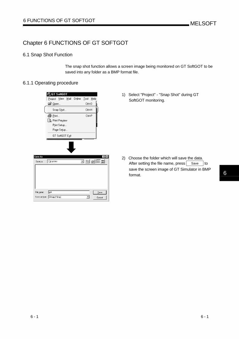
6 - 1 6 - 1
MELSOFT6 FUNCTIONS OF GT SOFTGOT
Chapter 6 FUNCTIONS OF GT SOFTGOT
6.1 Snap Shot Function
The snap shot function allows a screen image being monitored on GT SoftGOT to be
saved into any folder as a BMP format file.
6.1.1 Operating procedure
1) Select "Project" - "Snap Shot" during GT
SoftGOT monitoring.
2) Choose the folder which will save the data.After setting the file name, press Save to
save the screen image of GT Simulator in BMP
format. 6

6 - 2 6 - 2
MELSOFT6 FUNCTIONS OF GT SOFTGOT
6.2 Print Function
The print function allows a screen image being monitored on GT SoftGOT to be output
to a printer.
6.2.1 Operating procedure
1) Select "Project" - "Print" during GT SoftGOT
monitoring to start printing.
Note that printing cannot be done if the printer is
not specified.
6.2.2 Print preview
Selecting Print preview shows a printing image.
6.2.3 Page setup
Selecting Page setup shows the following dialog box.
1)
2)
Number Item Description
1) Image dataChoose "Reverse" to print the screen in reverse video.
(Defaults to "Normal".)
2) Margin
Set the margins on a page to be printed.When margins have been set, the screen to be printed is reduced according to the specifiedvalues.The reduction image of the screen can also be checked in Print preview.
6

6 - 3 6 - 3
MELSOFT6 FUNCTIONS OF GT SOFTGOT
6.3 Data Reference Function
It is possible to reference data of the following object functions stored on the hard diskof the personal computer:
Recipe function............................... References recipe data stored as CSV format files.Alarm history display function ........ References print image data of alarm history stored
as text format files or as CSV format files.Report function ............................... References print image data of reports stored as
text format files or as CSV format files.Hardcopy function .......................... References screen image data stored as BMP
format files.
Choose any
[Tool bar]
1) Choose any of the following.
"Tool" - "Recipe/Alarm History/Report/Hard
Copy"
Click the corresponding button on the tool bar.
(Only for Recipe, Alarm History, and Report)
"Tool" - "Recipe/Alarm History/Report/Hard
Copy" by right-clicking the mouse.
(Refer to Section 4.2 for right-clicking the mouse)
2) Select a file to be referenced.
Select the type of file to be referenced for
reference alarm history data or report data.
POINT Data cannot be updated while being referenced. (The data is held during thistime.)(The held data is reflected when the print data is updated after the data referenceis over.)
Use the format shown in Example 1 if tables are created in the alarm historydisplay function or report function.Tables with the format shown in Example 2 cannot be properly displayed in CSVfiles.
A B
X
Y
1 2
3 4
A B
X
Y
1 2
3 4
A B
X
Y
1 2
3 4
A B
X
Y
1 2
3 4
(Example 1) Table created with GT Designer
(Example 2) Table created with GT Designer
CSV file table
CSV file table

6 - 4 6 - 4
MELSOFT6 FUNCTIONS OF GT SOFTGOT
6.4 Mail Function
POINT If the mail function is used, e-mail is sent from GT SoftGOT, so mail software is
not required on the sending side.
In order to use the mail function, it is necessary to make a contract with a service
provider and set up the environment so that e-mail can be sent.
6.4.1 Mail function overview
It is possible to send messages from GT SoftGOT to personal computers and mobile
phones.
The mail function can only be used in the following object functions:
Alarm history display function
Time action function
(1) Using the alarm history display functionIt is possible to send error and recovery information at error/recovery of stations
using the alarm history display function.
Personal computer(GT SoftGOT)
Personal computer
Error occurrence or recovery
E-mail is sent.
E-mail is sent.
Mobile phone
(2) Using the time action functionIt is possible to send alarm history data, recipe data, and screen images stored in
"Memcard" at the specified date and time using the time action function.
Personal computer(GT SoftGOT)
Personal computer
Date and time set by the time action function
E-mail is sent.

6 - 5 6 - 5
MELSOFT6 FUNCTIONS OF GT SOFTGOT
6.4.2 Operation flow when using the mail function
The following flowchart shows operations involved in using the mail function of GT
SoftGOT.
Start
Refer to GT Designer Help function
Refer to GT Works Version5/GT Designer Version5Operating Manual (Start up Manual).
Refer to section 6. 4. 3.
Refer to section 5. 7.
Create the monitor screen data using GT Designer (Define the mail transmission settings by each object function).
Start up GT SoftGOT.
Set the mail destination.
Test the mail transmission.
Check the mail transmission conditions as necessary.
Read in the monitor screen data and start monitoring.
End(E-mail is sent to personal computers or mobile phones
when the conditions are met.)

6 - 6 6 - 6
MELSOFT6 FUNCTIONS OF GT SOFTGOT
6.4.3 How to set up the mail function
The following explains how to set up the mail function to send e-mail using GT
SoftGOT.
Mail Setup.......... Used to set the mail destination and perform a mail transmission test.
Mail Condition ... Used to set the mail transmission conditions.
Choose any
[Tool bar]
1) Choose any of the following to set up the mail
function:
"Mail" - "Mail Setup/Mail Condition"
"Mail Setup/Mail Condition" in the tool bar
"Mail" - "Mail Setup/Mail Condition" by right-
clicking the mouse.
(Refer to Section 4.2 for right-clicking the mouse)
(Send Mail setup dialog box) 2) As the Send Mail setup dialog box or Mail
Condition dialog box appears.make settings.
(Refer to Section 6.4.3 (1), (2))Clicking the OK button closes the dialog
box.

6 - 7 6 - 7
MELSOFT6 FUNCTIONS OF GT SOFTGOT
(1) Contents of the mail setup dialogue boxThe settings necessary to send e-mail from GT SoftGOT to the target device are
defined below.
In addition, it is possible to perform mail transmission tests from this dialogue
box.
1)
2)
3)
4)
5)
6) 7) 8)
Number Item Description
Dialup Set whether or not to send e-mail via dialup. (The default is "Manual.")
Auto
Check this radio button to send e-mail via dialup.If "Auto" is checked, a connection to the mail server is made and e-mail is sent when the mail conditionsare established. The connection to the server is canceled after e-mail is sent.It is necessary to set "Entry," "Retry," and "Interval."
Manual(No dialup)
Check this radio button to send e-mail without using dialup.If "Manual" is set, the connection to the mail server is always active when e-mail is sent.The connection to the server is not canceled even after e-mail is sent.
EntrySelect the dialup connection entry name in Windows®.
Refer to the Help function in Windows® for how to create a dial up entry.
RetrySet the number of retries made if a dialup fails."0" to "10" (The default is "1.")
1)
IntervalSet the interval between retries."1" to "10" (minutes) (The default is "1.")
Mail Address Enter the origin, destination, server name, and title of mail.
FROM Enter the address of the mail origin.
TO Enter the address of the mail destination.
CC Enter the address of the mail destination (copy). (E-mail can be sent even this field is blank.)
BCC Enter the address of the mail destination (blind copy). (E-mail can be sent even this field is blank.)
SMTP Enter the mail server name.
2)
Subject Enter the title of the mail.
POP3 authenticationEnable the check box and enter the necessary information if POP3 authentication is required whensending e-mail. (The check box is disabled by default.)
POP3 Enter the POP3 server name.
User name Enter the user name.3)
Password Enter the password corresponding to the user name.

6 - 8 6 - 8
MELSOFT6 FUNCTIONS OF GT SOFTGOT
Number Item Description
4) Create mail historyEnable this check box to create a mail transmission history.
(The check box is disabled by default.)
5) Mail Test Test e-mail is sent to the destination by clicking the "Send" button.
6) OK Used to update the settings and close the dialog box.
7) Cancel Used to cancel the settings and close the dialog box.
8) Apply Used to update the settings.
If more than one address is entered, they should be separated with a space or a comma.
It is possible to enter up to 32 addresses per setting.
Up to 64 characters can be used for one address.

6 - 9 6 - 9
MELSOFT6 FUNCTIONS OF GT SOFTGOT
(a) Performing dialup (automatic)The following explains an outline of how to make the necessary settings inorder to perform dialup (automatically) by GT SoftGOT.
POINTRefer to the manual of the service provider and the Help function in Windows® for
how to set the dialup network connection.
1) Set up the modem to be used.
2) Double-click "My Computer" - "Dial-up Networking" in Windows®.
A wizard for creating dialup network connection is displayed. Followthe instructions on the screen to make the settings.
3) After creating the dialup network connection, double-click the iconcreated.
4) In the screen shown below, enter the user name and passwordspecified by the service provider and enable the "Save password"check box.When the setting is complete, click "Connect" and connect to theservice provider.If the connection is established successfully, cancel the connectionand close the dialogue box.
<Example of Windows® 98 screen>
Be sure to check
5) After making the settings mentioned above, it becomes possible toselect the entry set in "Entry" of the mail setting by GT SoftGOT.
REMARK
If you run "Dialup (Auto)," be sure to log on when you start Windows®.
If you do not log on, you can not check "Save password" in step 4) above.

6 - 10 6 - 10
MELSOFT6 FUNCTIONS OF GT SOFTGOT
(b) Mail test
It is possible to check whether e-mail can be sent properly before starting
monitoring by GT SoftGOT.
In the mail test, the following sample massage of GT SoftGOT is sent to the
destination based on the definition set in the Mail Setup dialogue box.
1) GT SoftGOT sample message displayed at the destination.
SoftGOT TEST MAIL
This is testmail.
POINTIf "Create mail history" is checked in the Mail Setup dialogue box, the status of the
mail test is saved as one of the history data items.
Refer to Section 6.4.5 for a description of the mail history.
(2) Mail Condition Setup dialogue boxIf the mail transmission is set with GT Designer, it is possible to set not to send e-
mail for certain functions without modifying the monitor screen data.
Disable the functions for which e-mail is not to be sent.
(Check boxes are enabled by default.)
POINTIf the mail function is not set by each object function, this setting is ignored for that
function (e-mail is not sent even if the check boxes are checked).
Refer to the Help function of GT Designer for how to set objects.

6 - 11 6 - 11
MELSOFT6 FUNCTIONS OF GT SOFTGOT
6.4.4 Sending e-mail
When e-mail is sent from GT SoftGOT to the target device, the reception header part
shown at the destination displays a message that shows that the e-mail is from GT
SoftGOT.
(a) Example of display in the reception header part at the destination
From : *****************To : ********************Cc : ********************Subject : GT SoftGOT
X-Mailer : GT SoftGOT (Version5)
POINT The format and contents of the display of e-mail sent vary depending on the mailerspecifications used at the destination.
When e-mail is sent to a mobile phone, the display may vary depending on thespecifications (screen size) of the mobile phone.
GT SoftGOT can send up to 64 e-mail at one time. If alarms occur 65 times ormore, the 65th e-mail and subsequent are not sent.
(1) When sending e-mail using the alarm history display functionIf an alarm occurs in GT SoftGOT, the time and information of the alarm are sentto the destination by e-mail.Moreover, if the alarm recovers, the time and information of the alarm recoveryare sent to the destination by e-mail.For the details of the alarm history display functions, refer to the GT Designerhelp function.
(a) Example of display at the destination (when an alarm occurred)
[Alarm history occurred information][Occur Time] 2001/01/15 13:29:22[Occur Information] Line A supply conveyor stopped.[Detailed Information]Alarm history: A-line supply converter stopped. Check the power source.
1)
2)
1) The comment entered in the alarm history display function is displayed.2) The content of detailed display entered in the alarm history display
function is displayed."Detailed In formation" is not displayed if the details of the alarm historydisplay function are set to be displayed in the base screen or windowscreen.[Detailed Information] is not displayed if the detail display setting of thealarm history display function has not been made or if it has been madeto the base screen or window screen."detail comment nothing" appears under [Detailed Information].Set the details to be displayed in the comment window in order todisplay the "Detailed In formation".

6 - 12 6 - 12
MELSOFT6 FUNCTIONS OF GT SOFTGOT
(b) Example of display at destination (when an alarm recovered)
[Alarm history repaired information][repair Time] 2001/01/15 13:40:59[repair Information] Alarm "Line A supply conveyor stopped." recovered.
(2) When sending e-mail using the time action functionE-mail with the following data attached is sent to the destination at the day of the
week/time set with GT designer.
Alarm history data.......... CSV format file
Recipe data.................... CSV format file
Display image ................ BMP format file
For the details of the time action functions, refer to the GT Designer help
function.
(a) Example of display at destination (when alarm history data is sent)
[Time Action][Attribute]Daily SUN,FRI[Start time] 12:20:00Attached file Alarm history data
Alarmhst.csv
POINTOwing to the specification of the mobile phone to use, the e-mail with data may not
be sent.
For the details, refer to the manual of the mobile phone to use.

6 - 13 6 - 13
MELSOFT6 FUNCTIONS OF GT SOFTGOT
6.4.5 Mail history
It is possible to reference the operation history data of the e-mail sent from GT
SoftGOT.
It is also possible to reference the errors generated at the time e-mail was sent.The mail history data can be displayed using Notepad or a similar editor in Windows®.
(1) How to reference mail historyThe following explains how to reference the mail history data.
Choose any
[Tool bar]
1) Choose any of the following to reference mail
history:
"Mail" - "Mail History"
"Mail History" in the tool bar
"Mail" - "Mail History" by right-clicking the
mouse.
(Refer to Section 4.2 for right-clicking the mouse)
(a) Example of mail history data display
2000/12/23 13:40:57 SMTP:***** Serch...2000/12/23 13:40:58 SMTP:***** Connect...2000/12/23 13:40:58 SMTP:***** Connect Complete.2000/12/23 13:40:58 Sendmail Complete.2000/12/23 14:01:23 SMTP:***** Serch...2000/12/23 14:01:29 SMTP:***** is not found.2000/12/23 14:01:29 Sendmail can not Complete.2000/12/23 14:01:29 <ErrCode:***> *******************
POINT The mail history cannot be referenced if the data does not exist.
In order to create a mail history, enable "Create mail history" in the Mail Setup
dialogue box.
Refer to Section 6.4.4 for a description of the Mail Setup dialogue box.
The mail history data is not deleted even if GT SoftGOT is closed.
The user should delete any history data that is no longer necessary.

6 - 14 6 - 14
MELSOFT6 FUNCTIONS OF GT SOFTGOT
6.5 Keyboard input function
The following operations can be performed using the keyboard input function.
• Input operations using the numerical input function and the ASCII input function can
be performed from the keyboard.
• The numerical input function, ASCII input function, data list display function, alarm list
display function and alarm history display function can be executed from the
keyboard by assigning key codes to function keys (F1 to F8, [Shift]+F1 to [Shift]+F8).
6.5.1 Keyboard Input Enabling/Disabling Procedure
Choose any
[Tool bar]
2) KeyBoard Disable1) KeyBoard Enable
1) Input from the keyboard is disabled by default.
Therefore, if you want to input from the
keyboard, select one of the following.
• "Set" - "KeyBoard Enable"
• "KeyBoard Enable" on tool bar
• "Mail" - "KeyBoard Enable" by right-clicking the
mouse.
(Refer to Section 4.2 for right-clicking the mouse)
2) If you want to disable keyboard input again,
select one of the following.
• "Set" - "KeyBoard Disable"
• "KeyBoard Disable" on tool bar
• "Mail" - "KeyBoard Disable" by right-clicking the
mouse.
(Refer to Section 4.2 for right-clicking the mouse)
6.5.2 When operating the numerical input function or the ASCII input function from thekeyboard of a PC
When using the numerical input function or the ASCII input function, numeric
values/ASCII codes can be entered from the keyboard of a PC.
The following lists the operation when each key is pressed.
Type of keyOperation when entering a
numeric value
Operation when entering ASCII
code
[Back Space] keyErases the least significant digit and shifts the entire content one
digit to the right.
[Enter] keyConfirms the current operation, writes to a device, and closes the
current dialog box.
[Esc] key Displays/erases the cursor.
[-] key Inputs a minus sign.
[.] key Inputs a decimal point.
Numeric key Inputs numeric values (0 to 9).
Alphabetic key Input alphabetic letters (A to F).
Inputs ASCII code, shift JIS
code, and letters.
Arrow key Moves the cursor.
[Delete] key Erases a character being input.

6 - 15 6 - 15
MELSOFT6 FUNCTIONS OF GT SOFTGOT
6.5.3 How to Use the Function Keys
The numerical input function, ASCII input function, data list display function, alarm list
display function and alarm history display function can be executed from the keyboard
by assigning key codes to function keys (F1 to F8, [Shift]+F1 to [Shift]+F8).
For more information about the key codes of each function, refer to the GT Works
Version 5/GT Designer Version 5 Reference Manual.
(1) Assigning the key codesAssign key codes to the Edit Operation panel dialog box of GT Designer.
F1
F2
F3
F4
F5
F6
F7
F8
Assign Shift + F1 to Shift + F8 .
Assign F1 to F8 .
6.5.4 Precautions for Use
(1) When a window screen is displayed over a base screen, and the alarm list display
function or the alarm history display function has been set up on both the screens,
key input is enabled for the alarm list display function or the alarm history display
function on the base screen.
(2) Do not set up multiple alarm list display functions or do not set up both the alarm list
display function and the alarm history display function on a single base screen.
If set up, the operations assigned to the function keys may not be performed
properly.
(3) No operation is performed even if a key is pressed while the touch switch to prohibit
simultaneous key pressing is ON.
(4) If any key input is performed while executing screen save, the screen save is
cancelled. (The key entered does not operate as the key input function.)
(5) If both key code “000D” (Enter key) and operation setting are specified to a function
key using the numerical input function or the ASCII input function, the operation
specified by the operation setting will not be performed.

6 - 16 6 - 16
MELSOFT6 FUNCTIONS OF GT SOFTGOT
6.6 Full Screen Mode Function
You can display the full monitor screen of GT SoftGOT on the personal computer
screen.
When the full screen modefunction is not used
When the full screen mode function is used
When the full screen mode function is not used, the frame part is displayed.
When the full screen mode function is used, the frame part is hidden and the full monitor screen can be displayed on the personal computer.
POINT• When using the full screen mode function, you cannot perform such operations as
exiting from GT SoftGOT, since the menu bar, toolbar and status bar of GTSoftGOT are hidden.To perform operations of the menu bar and toolbar, use the mouse right-clickmenu.
• If the full screen mode function is canceled, the toolbar and status bar remainhidden.To display them, perform menu operation or right-click the mouse.
6.6.1 Full screen mode function types
There are the following full screen mode function types.
(1) Full screen 1Only a monitor screen is displayed fully on the screen.
Use this function with the personal computer or panel computer where a mouse
and keyboard are connected.
<Operation procedure>
1) The operations performed on the menu bar and
toolbar can be performed by right-clicking the
mouse.
2) Hold down the [Shift] key and double-click on the
monitor screen to minimize the screen.
3) Press the F12 key (function key) to exit from GT
SoftGOT.

6 - 17 6 - 17
MELSOFT6 FUNCTIONS OF GT SOFTGOT
(2) Full screen 2A monitor screen is displayed fully on the screen with a small dialog. GT
SoftGOT can be minimized/exited in the small dialog.
Since GT SoftGOT can be exited on the monitor screen, it can be used on the
panel computer where a mouse and keyboard are not connected.
<Operation procedure>
1) The following operations can be performed in the
small dialog.
• Min: Minimizes GT SoftGOT.
• Exit: Exits GT SoftGOT.
2) The operations performed on the menu bar and
toolbar can be performed by right-clicking the
mouse.
3) Hold down the [Shift] key and double-click on the
monitor screen to minimize the screen.
4) Press the F12 key (function key) to exit from GT
SoftGOT.
(3) Full screen 3A monitor screen is displayed fully on the screen with a small dialog. GT
SoftGOT can be opened/monitored/minimized/exited in the small dialog.
Since GT SoftGOT can be exited on the monitor screen, it can be used on the
panel computer where a mouse and keyboard are not connected.
<Operation procedure>
1) The following operations can be performed in the
small dialog.
• Open: Opens a project.
• Online: Starts monitoring.
(Cannot be selected during
monitoring.)
• Min: Minimizes GT SoftGOT.
• Exit: Exits GT SoftGOT.
2) The operations performed on the menu bar and
toolbar can be performed by right-clicking the
mouse.
3) Hold down the [Shift] key and double-click on the
monitor screen to minimize the screen.
4) Press the F12 key (function key) to exit from GT
SoftGOT.
POINTTurning ON the GOT internal device (system information area of GT SoftGOT:GS500.b0) exits GT SoftGOT.By setting the above device as a touch switch, you can exit GT SoftGOT withoutusing a mouse and keyboard.For details of the GOT internal device, refer to the GT Works Version5/GT DesignerVersion5 Reference Manual.

6 - 18 6 - 18
MELSOFT6 FUNCTIONS OF GT SOFTGOT
6.6.2 Setting method
The full screen mode can either be set before or after starting GT SoftGOT.
(1) Method of setting before starting GT SoftGOT
1) Choose the GT SoftGOT icon in the
C:/Windows/startmenu/program/MELSOFT
application and right-click the mouse to select
the [Properties] menu.
(If the GT SoftGOT starting icon was not
registered at the time of installation, create the
shortcut of the GT SoftGOT execution file
(.EXE).)
<For display in full screen 1 mode>
Add " -NOFRAME" at the end.
One space
2) As the GT SoftGOT properties appear, choose
the shortcut tab and add the keyword of the
mode to be used to "Target".
• Full screen 1: " -NOFRAME"
• Full screen 2: " -NOFRAMEDLG"
• Full screen 3: " -NOFRAMEDLGMENU"
3) After addition, click the [OK] button.
4) When GT SoftGOT is started next, GT
SoftGOT is started in the full screen mode.
5) When you want to cancel the full screen
mode, delete the keyword added to "Target".

6 - 19 6 - 19
MELSOFT6 FUNCTIONS OF GT SOFTGOT
(2) Method of setting after starting GT SoftGOT
POINT This setting is also made valid when you exit and restart GT SoftGOT.
When the full screen mode is set after the start of GT SoftGOT, GT SoftGOT is
displayed in the full screen 1 mode.
When you want to display GT SoftGOT in the full screen 2 or 3 mode, set the full
screen mode in the method (1).
When you have set the full screen mode in the method (1), you cannot cancel the
full screen mode in this method.
To cancel the full screen mode, delete the keyword that was added to the link
destination in (1).
1) Choose either of the following.
• "View" - "Full screen mode"
• "View" - "Full screen mode" by right-clicking the
mouse.
(Refer to Section 4.2 for right-clicking the mouse)
2) GT SoftGOT is displayed in the full screen 1
mode.
3) To cancel the full screen mode, right-click the
mouse and select "View" - "Full screen mode
cancel".
6.6.3 Precautions for use
(1) The small dialog is movable but cannot be closed.
It is always displayed in the front position.

6 - 20 6 - 20
MELSOFT6 FUNCTIONS OF GT SOFTGOT
6.7 Disable/Enable of Popupmenu
The right-click of the mouse can be disabled (the menu can be hidden).
When the Popupmenu is set to be disabled, the menu is not displayed if you right-click
the mouse.
This setting is also enabled when you exit and then restart GT SoftGOT.
6.7.1 Setting method
1) Choose either of the following.
• "Set" - "Popupmenu ineffective"
• "Set" - "Popupmenu ineffective" by right-clicking
the mouse.
(Refer to Section 4.2 for right-clicking the mouse)
2) The right-click of the mouse is disabled.
3) When you want to enable the right-click of the
mouse again, choose "Set" - "Popupmenu
effective".
6.7.2 Precautions for use
(1) When the full screen mode and Poppuppmenu disable are set, the operations of
the menu bar and mouse right-click menu cannot be performed. Therefore, the
pop-up menu cannot be enabled until the full screen mode is canceled.
When you want to enable the pop-up menu, cancel the full screen mode in the
following method.
(a) When the keyword of the full screen mode was added to the property of the
GT SoftGOT icon.
After exiting GT SoftGOT (pressing the [F12] key or turning ON the GOT
internal device GS500.b0), delete the added keyword.
(b) When the full screen mode was executed from the menu.
As the full screen mode is canceled by pressing the [Alt] + [F9] key, enable
the Popupmenu from the menu.

7 - 1 7 - 1
MELSOFT7 TROUBLESHOOTING
Chapter 7 TROUBLESHOOTING
7.1 Error messages
The following table indicates the error messages displayed during use of GT SoftGOT,
their definitions and causes, and corrective actions.
Type Error message Definition and cause Corrective action
GOT type of the project is not correct.
GOT type of the read project is otherthan the GOT-A900 series (GOT-F900series). The project's GOT type has beenselected to GOT with resolution of 640 x480 dots or less.
Change the GOT type of the projectcreated on GT Designer to the GOT-A900 series.Change the GOT type of projects createdwith GT Designer to GOT with aresolution of 640 x 480 dots or more.
PLC type of the project is different fromsetting 'GT SoftGOT'.
PLC type of the read project is differentfrom the setting on GT SoftGOT.
Make correction so that the PLC type ofthe project created on GT Designer is thesame as the CPU type of GT SoftGOT.
Cannot access the project file.Access to the specified project file couldnot be made.
Check the access right of the project file(e.g. a9gotp.got).
Screen data size is too large.Check to see if the screen data size is notmore than 9M bytes.
Hard disk is short of free space.Increase the free space of hard disk tomore than 50M bytes.
Since the message such as "This functioncan't be used now." is displayed on thescreen, read cannot be performed.
After choosing "OK" in the dialog box toerase the on-screen message, performread again.
Waiting for the end processing of thescript function.(Waiting for offline mode)
After the message "Off-Line processingexecution" appears on the screen,perform read again.
Dow
nloa
d
Failed in reading.Please retry after checking the following. Data size and number of the data. Capacity of free disk. Please close Dialogue if it is displayed. Waiting for 'Offline mode'. Please wait atseveral seconds. File access privilege of the project file.
Access to the project file cannot be made.Check the access right of the project file(e.g. a9gotp.got).
Since the message such as "This functioncan't be used now." is displayed on thescreen, you cannot exit from GT SoftGOTproperly.
After choosing "OK" in the dialog box toerase the on-screen message, exit fromGT SoftGOT again.
The simulation cannot be ended.Please retry after shutting Dialogue on thesimulation screen There is the other internal cause than the
above that does not allow you to exit fromthe software.
After choosing "OK" in the dialog box, waitfor some time and exit from GT SoftGOTagain.
Please do logoff/the termination ofWindows after ending 'GT SoftGOT'.
Logoff/exit processing of Windows wasexecuted before exiting from GTSoftGOT.
After exiting from GT SoftGOT, executelogoff/exit processing of Windows.
Onl
ine
This function can’t be used now.You selected the function unusable withGT SoftGOT.
Press "OK".
Cable is disconnected.
Cable is open.Check the cable.
Transmission speed (baudrate) is
incorrect.
Check the transmission speed (baudrate)
of the CPU.check communication
Connection target PLC differs from the
PLC type of the project.Check the connection target PLC.
Cable is disconnected.Cable is open.
Transmission speed (baudrate) isincorrect.
Com
mun
icat
ion
Communication error occurred. Retry : Communication begins again. Cancel : Communication is interrupted.
Please reexecute 'GTSoftGOT', if communicateagin. Connection target PLC differs from the
PLC type of the project.
After checking for the left causes, choosethe button in the displayed dialog box."Retry"
Restarts communication."Cancel"
After Cancel is selected, allcommunications will not be made.When performing monitor, restart GTSoftGOT.
7

7 - 2 7 - 2
MELSOFT7 TROUBLESHOOTING
Type Error message Definition and cause Corrective action
The license key is necessary to operate
GT SoftGOT ends at about 10 minutes
when executing without installing the
license key.
License
key
(for
DOS/V
personal
computer)
The license key is not installed.
GT SoftGOT is ended.
The license key is not installed. Check that the license key is installed.
This License key floppy disk is only for
PPC-CPU.
The license registration destination is not
the PC CPU module.
Register the license to the PC CPU
module with the license key FD.
This is a illegal License key floppy disk.
Please insert the master floppy disk.
The floppy disk of the copied license key
FD is inserted.
Register the license with the regular
license key floppy disk.
Failed to disable the product. Please use
the License key floppy disk which you
used to enable the product for disabling
too.
An attempt was made to register a new
license to the personal computer CPU
module where the license has already
been registered.
Register a new license after canceling the
license with the license key FD that was
used to register the license.
Failed to enable the product, because this
License key floppy disk has no license.
An attempt was made to register the
license with the license key FD that does
not hold the license.
Register the license using the license key
FD that holds the license.
License
key FD
(for PC
CPU
module)
Failed to write on floppy disk. Please
remove the write protect of floppy disk.The license key FD is write-protected.
Write-enable the write-protected license
key FD.
System
driver
The system driver to access the license
key is not installed.
Please install the system driver.
The system driver has not been installed. Install the system driver.
POINTRegarding the communication time-out (system alarm 402) during Ethernet
connection.
If a part of communication is in the condition of time-out error, “402 communication
time-out” is displayed on the system alarm. (The dialog of communication will not
be displayed.)
When the above error occurs, confirm the following.• N/W No, PC No and IP address are correctly set for Ethernet setting.• All of the other stations specified for Device setting are available.• If the heavy load of PLC prevents the communication from completing within the
time-out value set in advance, set the value larger.
7

7 - 3 7 - 3
MELSOFT7 TROUBLESHOOTING
7.2 Troubleshooting Related to the License Key
Check the following items if the license key is not recognized even if it has been
installed on the DOS/V personal computer or the printer does not operate properly
after being connected on the external side of the license key.
Problem Definition and cause Corrective action
The license key is connected to the
personal computer’s serial port.Connect the license key to the printer port.
The license key is installed on the DOS/V
personal computer via the printer switch
(the devices are installed in the order from
the DOS/V personal computer, then the
printer switch, and then the license key).
Install the license key closer to the DOS/V
personal computer than the printer switch
(i.e., install the devices in the order from
the DOS/V personal computer, then the
license key, and then the printer switch.)
It is possible that the power supply to the
printer port is shut off via setting of the
DOS/V personal computer.
Change the settings so that the printer port
can be used.
The system driver is not installed. Install the system driver.
The parallel port may not be used unless
the printer driver is set for each local portwhen using the Microsoft® Windows NT®
Workstation 4.0 operating system.
Install the necessary printer drivers.
(Complete the printer settings even if a
printer is not used.)
The license key cannot be recognized
In the case of a Fujitsu-made FM/V Series
computer
Install the system driver and restart the
DOS/V personal computer.
Cannot print
If a printer cable that is 5 m or longer is
used, the printing may be disturbed by
noise from the surroundings.
Check the cable length.
(Check the overall cable length when a
switch is used.)

7 - 4 7 - 4
MELSOFT7 TROUBLESHOOTING
7.3 Troubleshooting Related to Mail Transmission
(1) TroubleshootingNo dialogue boxes are displayed by GT SoftGOT for errors related to mail
transmission and dialup.
Problem Definition and cause Corrective action
The mail send setting of GT SoftGOT has
not been made.
Mail send setting has been made on GT
Designer.
Make the mail send setting of GT SoftGOT.
(Refer to Section 6.4.)Mail is not sent.
The mail send setting method is wrong.Reexamine the mail send setting of GT
SoftGOT.
(2) Error codeNo dialogue boxes are displayed by GT SoftGOT for errors related to mail
transmission and dialup.
Refer to the mail history data for error codes and error messages.
Refer to Section 6.4.5 for how to reference the mail history data.
The following table lists the error codes related to mail transmission and dialup,
their definitions and causes, and the corrective actions to take:
Error code Definition and cause Corrective action
600 to 750sSetting errors of personal computers and
peripheral devices (e.g., modem)Refer to the Help function in Windows®.
POINT"SMTP Error Report : ************" is displayed in the mail history data if an error is
reported from the mail server.
Consult the server administrator if this type of error occurs.

App - 1 App - 1
MELSOFTAPPENDIX
APPENDIX
Appendix1 List of Functions Added to Update GT SoftGOT
The following indicates the functions added to up to Version 29F of GT SoftGOT
Version 5.
: Allowed for use
: Not allowed for use
POINTIn addition to the functions given in the following table, GT SoftGOT is also
compatible with an update to GT Designer. For details of a GT Designer update,
refer to the GT Works Version 5/GT Designer Version 5 Reference Manual.
(1) Connection forms added
Version5Item
J K P R U 26C 29F
Ethernet Connection
Q Buss Connection
Computer link Connection
Connection with multiple PLC system
Connection with MELSEC-Q Series Q00J/Q00/Q01CPU
Connection with MELSEC-Q Series Q12PHCPU/Q25PHCPU
MELSECNET/10, MELSECNET/H connection
(2) GT SoftGOT forms added
Version5Item Description
J K P R U 26C 29F
Alarm occurrence or recovery from alarm is sent by e-
mail using the alarm history display function.Mail
The alarm history data/recipe file/screen image is sent
by e-mail using the time action function.
Keyboard inputThe numerical input function or ASCII input function is
entered from the keyboard of the personal computer.
Full screen mode Full screen is displayed on the personal computer.
PopupmenuSetting of whether the mouse right-click menu is
disabled or enabled.
APP

App - 2 App - 2
MELSOFTAPPENDIX
(3) Object functions added
Version5Item
J K P R U 26C 29F
Hard copyCompatible with the JPEG format when saving to the
PC card
(4) Other functions added
Version5Item Description
J K P R U 26C 29F
GT SoftGOT is used in the PC CPU module.
Operating
environment
Compatible with Microsoft® Windows® Millennium
Edition operating system or Microsoft® Windows®
2000 Professional operating system.
App

App - 3 App - 3
MELSOFTAPPENDIX
MEMO

Index - 1 Index - 1
INDEX
[A]Access range................................................. 2-13
Automatic Startup.......................................... 5-29
[C]Cable................................................................ 2-7
Clock display function ..................................... 2-4
Computer link units.......................................... 2-5
Converter ......................................................... 2-7
[D]Data Reference function ................................. 6-3
Description of the monitor data reading dialog box
....................................................................... 5-24
Disable/Enable of Popupmenu ..................... 6-20
[E]Error messages ............................................... 7-1
Ethernet units and Ethernet boards/cards...... 2-5
Execution of monitor ..................................... 5-21
Exiting from GT SoftGOT.............................. 5-25
[F]Full screen mode function............................. 6-16
Function that cannot be Used......................... 3-2
[H]How to Attach the License Key....................... 5-2
How to set up the Computer link connection
....................................................................... 5-18
How to set up the Ethernet connection .......... 5-3
How to set up the mail function....................... 6-6
[I]Install the system driver .................................. 5-2
[K]KeyBoard input function................................ 6-14
[L]List of functions added to updated GT SoftGOT
Version5..............................................Appendix-1
[M]Mail function .....................................................6-4
Mail function overview .....................................6-4
Mail history .....................................................6-13
MELFANSweb .................................................4-3
Memory card save ...........................................3-4
Menu configuration ..........................................4-3
Monitor data that may be monitored ...............3-4
[N]Network units, Network boards .......................2-6
[O]Opening the project .......................................5-22
Operating procedure overview ........................5-1
Operation at Monitoring .................................5-25
Operation environment ....................................2-1
Operation at monitoring .................................5-25
Operation flow when using the mail function ..6-5
Option Setting ................................................5-18
Option Setting Dialog Box .............................5-19
[P]Page setup .......................................................6-2
PLC CPUs........................................................2-4
Print Function ...................................................6-2
Print preview ....................................................6-2
[Q]Q bus connection...........................................2-14
[R]Restrictions on and instructions for use of GT
SoftGOT ...........................................................3-4
Restrictions on and instructions for PLC CPU
connection........................................................3-5
Ind

Index - 2 Index - 2
[S]Screen Configuration
Title bar ........................................................ 4-1
Menu bar...................................................... 4-1
Dropdown menu .......................................... 4-1
Monitor screen............................................. 4-1
Tool bar........................................................ 4-2
Status bar..................................................... 4-2
Sending e-mail............................................... 6-11
Serial communication units ............................. 2-5
Snap shot function........................................... 6-1
Specifications of the GT SoftGOT .................. 3-1
System configuration
System configuration at installation of GT
SoftGOT....................................................... 2-1
System configuration for GT SoftGOT Excution
..................................................................... 2-2
System monitor function ................................. 3-2
[T]Troubleshooting............................................... 7-2
Troubleshooting Related to Mail Transmission7-3
Troubleshooting Related to the License Key . 7-2
[U]Utility function .................................................. 3-3
Ind

Microsoft Windows, Microsoft Windows NT are registered trademarks of Microsoft Corporation in theUnited States and other countries.Pentium is a registered trademark of Intel Corporation in the United States and other countries.Other company and product names herein are either trademarks or registered trademarks of theirrespective owners.SPREADCopyright (C) 1998 Farpoint Technologies, Inc.

GT SoftGOT Version5
Operating ManualOperating Manual
MITSUBISHI Graphic Operation Terminal
GT SoftGOT Version5
MELSOFT SW5D5C-GTWORKS-EIntegrated Software
SW5-SOFTGOT-O-E
1DM193
SH(NA)-080156-G(0406)MEE
MODEL
MODELCODE
O
GT
SoftG
OT
Version5 O
perating Manual
MONO
Specifications subject to change without notice.
When exported from Japan, this manual does not require application to theMinistry of Economy, Trade and Industry for service transaction permission.
HEAD OFFICE : 1-8-12, OFFICE TOWER Z 14F HARUMI CHUO-KU 104-6212,JAPANNAGOYA WORKS : 1-14 , YADA-MINAMI 5-CHOME , HIGASHI-KU, NAGOYA , JAPAN


![GT Simulator Version5 Operating Manual...Please save this manual to make it accessible when required and always forward it to the end user. [Test Operation Precautions]! DANGER •](https://img.dokumen.tips/doc/110x75/60b1f26cd600551afd230b8c/gt-simulator-version5-operating-manual-please-save-this-manual-to-make-it-accessible.jpg)


![Medeia Informatica Version5 0 [1]](https://img.dokumen.tips/doc/110x75/5596104b1a28ab5c678b4820/medeia-informatica-version5-0-1-559647c8f00e4.jpg)