Embed Size (px)
DESCRIPTION
This GSM Modem can accept any GSM network operator SIM cardand act just like a mobile phone with its own unique phone number. Ad-vantage of using this modem will be that you can use its RS232 port tocommunicate and develop embedded applications. Applications like SMSControl, data transfer, remote control and logging can be developed easily.
Citation preview

ELEMENTZ ENGINEERS GUILD PVT LTD
Embedded Module Manufacturers and Distributors
SIM900A GSM MODEM
USER GUIDE
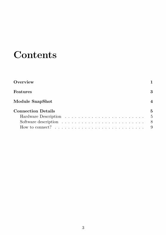
Contents
Overview 1
Features 3
Module SnapShot 4
Connection Details 5Hardware Description . . . . . . . . . . . . . . . . . . . . . . . . 5Software description . . . . . . . . . . . . . . . . . . . . . . . . . 8How to connect? . . . . . . . . . . . . . . . . . . . . . . . . . . . 9
3

CONTENTS CONTENTS
4

Overview
This GSM Modem can accept any GSM network operator SIM cardand act just like a mobile phone with its own unique phone number. Ad-vantage of using this modem will be that you can use its RS232 port tocommunicate and develop embedded applications. Applications like SMSControl, data transfer, remote control and logging can be developed easily.
The modem can either be connected directly to the PC serial port or toany microcontroller through MAX232. It can be used to send and receiveSMS or to make/receive voice calls. It can also be used in GPRS modeto connect to the internet and do many applications for data logging andcontrol. In GPRS mode you can also connect to any remote FTP serverand upload files for data logging.
1
USER MANUAL GSM MODEM
www.elementzonline.com 2
Features
• Dual-Band GSM/GPRS 900/1800 MHz
• Configurable baud rate ( 9600 to 115200 )
• SIM Card holder.
• Built in Network Status LED
• Inbuilt Powerful TCP/IP protocol stack for internet data transferover GPRS.
• Normal operation temperature: −20 ◦C to +55 ◦C
• Single supply voltage 9V to 12V (DC).
• RS232 output to connect directly to computer
3
USER MANUAL GSM MODEM
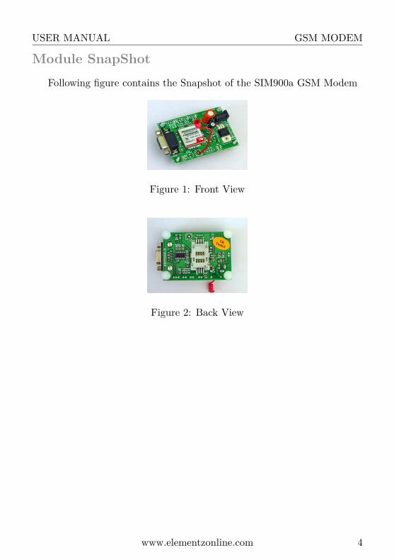
Module SnapShotFollowing figure contains the Snapshot of the SIM900a GSM Modem
Figure 1: Front View
Figure 2: Back View
www.elementzonline.com 4

Connection Details
To connect the GSM modem with the pc, we have to know about thehardware and the software section used in this type of modem.
Hardware DescriptionThe hardware section consists of a SIM900A IC, RS232, MAX232,
LM317, DC jack, red and blue LEDs, a SIM slot and an antenna.
SIM900A IC
The SIM900A is a Dual-band (900/1800MHz) GSM/GPRS modem. Ithas low power consumption and is cost-effective.
Figure 3: SIM900 IC
RS232
The information transferred between data processing equipment andperipherals is in the form of digital data which is transmitted in either aserial or parallel mode. Parallel communication is used mainly for connect-ing test instruments or printers with the computer, while serial is often usedbetween computers and other peripherals. Serial transmission involves the
5
USER MANUAL GSM MODEM
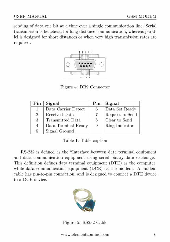
sending of data one bit at a time over a single communication line. Serialtransmission is beneficial for long distance communication, whereas paral-lel is designed for short distances or when very high transmission rates arerequired.
Figure 4: DB9 Connector
Pin Signal Pin Signal1 Data Carrier Detect 6 Data Set Ready2 Received Data 7 Request to Send3 Transmitted Data 8 Clear to Send4 Data Terminal Ready 9 Ring Indicator5 Signal Ground
Table 1: Table caption
RS-232 is defined as the “Interface between data terminal equipmentand data communication equipment using serial binary data exchange.”This definition defines data terminal equipment (DTE) as the computer,while data communication equipment (DCE) as the modem. A modemcable has pin-to-pin connection, and is designed to connect a DTE deviceto a DCE device.
Figure 5: RS232 Cable
www.elementzonline.com 6
USER MANUAL GSM MODEM
TRANSMITTED SIGNAL VOLTAGE LEVELS:→ Binary 0: +5 to +15 Vdc (called a “space” or “on”)→ Binary 1: -5 to -15 Vdc (called a “mark” or “off”)
RECEIVED SIGNAL VOLTAGE LEVELS:→ Binary 0: +3 to +13 Vdc→ Binary 1: -3 to -13 Vdc
MAX232
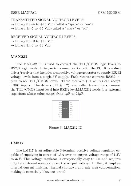
The MAX232 IC is used to convert the TTL/CMOS logic levels toRS232 logic levels during serial communication with the PC. It is a dualdriver/receiver that includes a capacitive voltage generator to supply RS232voltage levels from a single 5V supply. Each receiver converts RS232 in-puts to 5V TTL/CMOS levels. These receivers (R1 & R2) can accept±30V inputs. The drivers (T1 & T2), also called transmitters, convertthe TTL/CMOS input level into RS232 level.MAX232 needs four externalcapacitors whose value ranges from 1µF to 22µF.
Figure 6: MAX232 IC
LM317
The LM317 is an adjustable 3-terminal positive voltage regulator ca-pable of supplying in excess of 1.5A over an output voltage range of 1.2Vto 37V. This voltage regulator is exceptionally easy to use and requiresonly two external resistors to set the output voltage. Further, it employsinternal current limiting, thermal shutdown and safe area compensation,making it essentially blow-out proof.
www.elementzonline.com 7

USER MANUAL GSM MODEM
Figure 7: LM317
DC Jack
It is used to connect the external power supply.
Figure 8: DC Jack
Red and Blue LED
These are SMD LEDs, were red LED is used to indicate the ON-OFFstatus of the GSM modem and blue LED is used to know whether theGSM modem is connected to its network or not.
SIM slot
The SIM card is inserted in this slot.
Antenna
It is used to communicate between networks.
Software description
To communicate with the network we use putty software. It is an exe-cutable file which supports serial data transmission and reception similarto HyperTerminal in Windows XP.
www.elementzonline.com 8

USER MANUAL GSM MODEM
How to connect?
Connect the GSM modem to the pc using RS232 cable. Make sure thatthe SIM card is inserted before the connection was made. When the 12Vpower supply is connected to the GSM board, LM317 regulates the voltageup to 3.6V. Then a red LED will glow. It shows that the modem got theexternal DC power. At the same time, a blue LED will blink with a delayof approximately 5 sec. That means the SIM card has connected to thenetwork. If there is no SIM card in the modem, the blue LED blinks witha delay approximately 1 sec, i.e. lower than the delay with SIM card.
The steps required for connecting the modem to the PC is shown below:
Right click My Computer → select the Device manager
Figure 9: Computer Management
Double click ‘putty.exe’→ select serial bullet→ change the com portnumber to the number shown earlier in the device manager → click open.
Remarks Note that the default Baudrate configuration for SIM900A is9600.
Then a new window is opened and we give the commands in the windowto communicate with the GSM modem and the other network through
www.elementzonline.com 9
USER MANUAL GSM MODEM
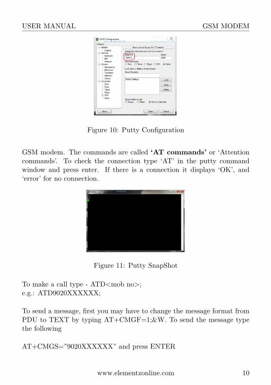
Figure 10: Putty Configuration
GSM modem. The commands are called ‘AT commands’ or ‘Attentioncommands’. To check the connection type ‘AT’ in the putty commandwindow and press enter. If there is a connection it displays ‘OK’, and‘error’ for no connection.
Figure 11: Putty SnapShot
To make a call type - ATD<mob no>;e.g.: ATD9020XXXXXX;
To send a message, first you may have to change the message format fromPDU to TEXT by typing AT+CMGF=1;&W. To send the message typethe following
AT+CMGS=”9020XXXXXX” and press ENTER
www.elementzonline.com 10
USER MANUAL GSM MODEM
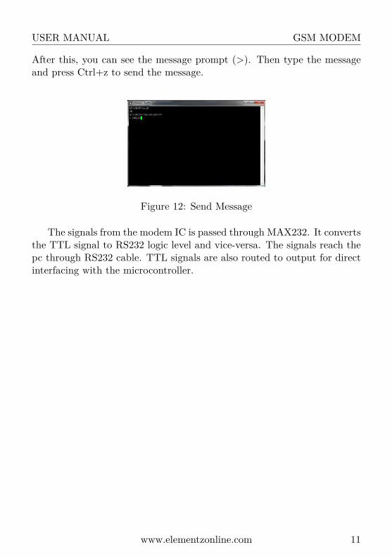
After this, you can see the message prompt (>). Then type the messageand press Ctrl+z to send the message.
Figure 12: Send Message
The signals from the modem IC is passed through MAX232. It convertsthe TTL signal to RS232 logic level and vice-versa. The signals reach thepc through RS232 cable. TTL signals are also routed to output for directinterfacing with the microcontroller.
www.elementzonline.com 11