Embed Size (px)
DESCRIPTION
GSM - Detailed information about logical channels and frames
Citation preview

2.1
BITS, Pilani Goa Campus
GSM – Logical Channels and Frame Structure
Mobile CommunicationsGSM
• Logical Channels and Frame Structure

2.2
BITS, Pilani Goa Campus
GSM – Logical Channels and Frame Structure
Logical Channels
• Large amount of data is constantly moved between MS and BTS – voice/data & signalling data
• Depending of the required information, different logical channels are used. These logical channels are mapped onto the physical channels -> time slots
• Digital speech is carried out in logical channel called traffic channel which during the transmission is allocated in certain time slot(s)
• Pre-allocation of time slots is not done -> just about any time slot / RF carrier can be used to number of tasks
• Two basic channles used for carrying user data or encoded speech data, both UL & DL directions.• Traffic Channel(s) • Control Channel(s)
• Cell Broadcast CHannel is defined in GSM standard but is not mandatory for the opertators to deploy

2.3
BITS, Pilani Goa Campus
GSM – Logical Channels and Frame Structure
Logical Channels

2.4
BITS, Pilani Goa Campus
GSM – Logical Channels and Frame Structure
Logical Channels
• Control CHannel (CCH) is divided to (3)• (1) Broadcast CHannel (BCH) -> DL channels
• Broadcast Contorl CHannel (BCCH)- contains specific parameters needed by a mobile in order that it can
identify the network and gain access to it. Typical information includes the LAC (Location Area Code) and RAC (Routing Area Code) and MNC (Mobile Network Code) – broadcasted continuously with ‘full’ power
• Frequency Correction CHannel (FCCH)- sends all-zero-burst to represent unmodulated carrier for MS to tune
accurately to BS.
• Synchronation CHannel (SCH)- The purpose of the SCH is to allow the mobile station (handset) to quickly
identify a nearby cell (a BTS and synchronize to that BTS's TDMA structures. Each radio burst on the SCH contains, the current frame clock of the serving BTS & the Base Station Identity Code (BSIC)
• (2) Common Control CHannel (CCCH) >used before DCCH assign• Paging CHannel (PCH) – DL• Acess Grant CHannel (AGCH) – DL• Random Access CHannel (RACH) – UL (DCCH req.)

2.5
BITS, Pilani Goa Campus
GSM – Logical Channels and Frame Structure
Logical Channels
• (3) Dedicated Control CHannel• Stand-alone Dedicated Control CHannel (SDCCH)
- Authnetication, location updates & TCH assignment- SDCCH can chare a channel with BCH and CCCH. So there can be 4
SDCCHs (SDCCH/4) mapped onto same phyical channel or there can be 8 SDCCHs (SDCCH/8) saring a physical channel
• Assiosiated Control CHannel (ACCH)- Slow Assiosiated Control CHannel (SACCH)> Used for most short transactions, including initial call setup step and
SMS transfer> SACCH can be sent along with Full or Half rate TCHs (SACCH/TF or
SACCH/TH) and it can be also sent along with SDCCH/4 and SDCCH/8 (SACCH/C4 & SACCH/C8)
- Fast Assiosiated Contorl CHannel (FACCH)> Call disconnect & Handove> FACCH is also used along with Full or Half rate TCHs (FACCH/F &
FACCH/H)
-

2.6
BITS, Pilani Goa Campus
GSM – Logical Channels and Frame Structure
Logical Channels
• Cell Broadcast CHannel
• Cell Broadcast (CB) A.K.A Short Message Service - Cell Broadcast (SMS-CB). Cell Broadcast service is designed for simultaneous delivery of messages to multiple users in a specified area. Whereas the SMS - Point to Point is a one-to-one & one-to-a-few service, Cell Broadcast is a one-to-many geographically focused messaging service. Also supported by UMTS, as defined by 3GPP.
• Can be used for nationwide or citywide alerting, weather reports, mass messaging, location based news, etc. All operators are not using the feature, and many handsets do not have the capability to support cell broadcast.
• Allows message distribution to all mobile terminals connected to a set of cells, messages > are sent point-to-area, Cell Broadcast messages are directed to radio cells, rather than to a specific terminal. CB is unconfirmed push service, meaning that the originator of the message does not know who has received the message, allowing for services based on anonymity.
• Cell Broadcast messaging has a number of features that make it particularly appropriate for emergency purposes:
• It is not as affected by traffic load; therefore, it may be usable during a disaster when load spikes tend to crash networks. Used for example in:
• 7 July 2005 London bombings - to send information to mobile users in the area• During the Tsunami catastrophe in Asia. Dialog GSM, an operator in Sri Lanka was able to provide
ongoing emergency information to its subscribers, to warn of incoming waves, to give news updates, to direct people to supply and distribution centres, and even to arrange donation collections
• Broadcast range can be varied, from a single cell to the entire network.

2.7
BITS, Pilani Goa Campus
GSM – Logical Channels and Frame Structure
1 2 3 4 5 6 7 8
higher GSM frame structures
935-960 MHz124 channels (200 kHz)downlink
890-915 MHz124 channels (200 kHz)uplink
frequ
ency
time
GSM TDMA frame
GSM time-slot (normal burst)
4.615 ms
546.5 µs577 µs
tail user data TrainingSguardspace S user data tail
guardspace
3 bits 57 bits 26 bits 57 bits1 1 3
GSM – Frame Structure

2.8
BITS, Pilani Goa Campus
GSM – Logical Channels and Frame Structure
GSM hierarchy of frames
0 1 2 2045 2046 2047...
hyperframe
0 1 2 48 49 50...
0 1 24 25...
superframe
0 1 24 25...
0 1 2 48 49 50...
0 1 6 7...
multiframe
frame
burst
slot
577 µs
4.615 ms
120 ms
235.4 ms
6.12 s
3 h 28 min 53.76 s

2.9
BITS, Pilani Goa Campus
GSM – Logical Channels and Frame Structure
Bursts
• ARFCN (Absolute Radio Frequency Channel Number)
• specifies a pair of physical radio carriers and channels used for transmission and reception on the Um Interface in GSM cellular networks, one for the uplink signal and one for the downlink signal.
• Each of the 8 users (of Frequency Channel) utilizes the same ARFCN and occupies an unique time slot per frame.

2.10
BITS, Pilani Goa Campus
GSM – Logical Channels and Frame Structure
Bursts
• Normal burst• 57 bits of data or speech• One bit ’ stealing flag’ -> whether the burst was stolen from
FACCH• Training sequence for creating the channel model• Tail bits (0,0,0) to provide start & stop bit patterns• Guard period to prevent overlap

2.11
BITS, Pilani Goa Campus
GSM – Logical Channels and Frame Structure
Bursts
• Synchronization Burst• Used for time synch for mobile• MS will know whatk kind of channel is being transmitted on
the CCH time slot 0
• Frequency correction Channel Burst• Zero burst to frequency correction of MS (unmodulated)
• Access Burst• Used for random access • Has longer guard time (MS might not know the timing)
• Dummy Burst• Used for sending synchonization info• No user data is sent

2.12
BITS, Pilani Goa Campus
GSM – Logical Channels and Frame Structure
Mobility Management
• GSM Networks are divided in to GPA - GSM PLMN Areas
• GPA’s consist of Location Areas (LA)• LA -> cluster of cells (A.K.A Routing Area)• MS registers it self to new LA and is free to move inside
without more registrations• When call is to be delivered to MS only the particular LA is
paged where the mobile is situated
• LA Indentification (LAI) code includes• Mobile Country Code (MCC)• Mobile Network Code (MNC)• LA Code (LAC)
• Global Cell identification includes LAI + Cell Indentity (CI)
• MSC covers 1 or more LAs, LA covers 1 or more BSS, BSS covers 1 or more cell areas

2.13
BITS, Pilani Goa Campus
GSM – Logical Channels and Frame Structure
LA & Cell Indentification
MCC MNC LAC
MCC = Mobile Country CodeMNC = Mobile Network CodeLA = Location Area CodeCI = Cell Identity
MCC MNC LAC CI
LAI
’Global Cell Indetification’

2.14
BITS, Pilani Goa Campus
GSM – Logical Channels and Frame Structure
Location Registration
• Geographical • BSS’s broadcast LAC, MS compares the new LAC with the last
LAC and registration is taken in place if change is detected.• When a mobile finds that the LAC is different from its last update, it
sends a location update request, together with its previous location
• Time based• MS registers periodically• Update intervals are proadcasted by BS (6 min -> 25 hours)• MS initiates update when time expires
• MS power on/off• MS power up is attach operation and causes registration• Power off is detach causes deregistration
• Delete VLR entry• Leave VLR entry, but flag detached
2.15
BITS, Pilani Goa Campus
GSM – Logical Channels and Frame Structure
MS identification
• International Mobile Subscriber Identity (IMSI) is a unique number associated with all GSM and UMTS network mobile phone users. • Stored in the SIM and is sent by the phone to the network. It
is also used to acquire other details of the mobile in the Home Location Register (HLR)
• IMSI is 15 digits long. The first 3 digits are the Mobile Country Code (MCC), and is followed by the Mobile Network Code (MNC). The remaining digits are the Mobile Subscriber Integrated Services Digital Network Number MSISDN.• MSISDN = CC + NDC + SN• CC = Country Code• NDC = National Destination Code• SN = Subscriber Number

2.16
BITS, Pilani Goa Campus
GSM – Logical Channels and Frame Structure
MS identification
• IMSI is sent as rarely as possible and a randomly-generated TMSI is sent instead.
• Temporary Mobile Subscriber Identity (TMSI) is the identity that is most commonly sent between the mobile and the network. TMSI is randomly assigned by the VLR to every mobile in the area, the moment it is switched on. The number is local to a location area, and so it has to be updated each time the mobile moves to a new geographical area.
• The network can also change the TMSI of the mobile at any time. And it normally does so, in order to avoid the subscriber from being identified, and tracked by eavesdroppers on the radio interface. This makes it difficult to trace which mobile is which, except briefly, when the mobile is just switched on. At that point, IMSI must be sent to the network.
• A key use of the TMSI is in paging a mobile. "Paging" is the one-to-one communication between the mobile and the base station. The most important use of broadcast information is to set up channels for "paging".

2.17
BITS, Pilani Goa Campus
GSM – Logical Channels and Frame Structure
MS identification - IMSI

2.18
BITS, Pilani Goa Campus
GSM – Logical Channels and Frame Structure
Signaling System 7
• In-Band Signalling• In telecommunications, in-band signaling is the sending of
metadata and control information in the same band, on the same channel, as used for data.
• In-band signaling is insecure because it exposes control signals, protocols and management systems to the user(s), which may result in falsing. -> blue boxes were popular in the 1960s and 1970s
• Falsing -> decoder assuming that it is detecting a valid input when one is not present.
• telephone answering machine detecting dial pulses from a rotary dial as ringing voltage. The result being that the answering machine answers in response to dialing.
• telephone circuit drops calls because it sees distorted waveform as a valid "on-hook" signal

2.19
BITS, Pilani Goa Campus
GSM – Logical Channels and Frame Structure
SS7
• Out-of-band signalling• Common data channel is used to convey signalling
information (between trunks)
• Signalling in ISDN• Signalling between user and network node – access
signalling• Digital Subscriber Signalling System No.1 (DSSS1)
• Signalling between network nodes – network signalling• Signalling System 7
• Common Channel Signaling protocols have been developed by major telephone companies and the ITU-T since 1975 and the first international Common Channel Signaling protocol was defined by the ITU-T as Signalling System No. 6 in 1977. Signalling System No. 7 was defined as an international standard by ITU-T in its 1980 (Yellow Book) Q.7XX-series recommendations. SS7 was designed to replace Signalling System No. 6, which had a restricted 28-bit signal unit that was both limited in function and not amenable to digital systems.

2.20
BITS, Pilani Goa Campus
GSM – Logical Channels and Frame Structure
SS7
• Signaling System Number 7 (SS7) is a set of telephony signaling protocols which are used to set up most of the world's PSTN calls.
• The main purpose is to set up and tear down telephone calls. • Number translation, prepaid billing mechanisms & short
message service (SMS)
• It is usually abbreviated as Signaling System No. 7, Signaling System #7, or just SS7. In North America it is often referred to as CCSS7 "Common Channel Signaling System 7". In UK it is sometimes called C7.
• There is only one international SS7 protocol defined by ITU-T in its Q.700-series recommendations. There are however, many national variants of the SS7 protocols. Most national variants are based on two widely deployed national variants as standardized by ANSI and ETSI

2.21
BITS, Pilani Goa Campus
GSM – Logical Channels and Frame Structure
SS7 Network modes
• Assiciated mode• ’Directly interconnected singnalling relation’ – two signalling
points are in signalling reation in ’direct link’
• Nonassociated mode• Two nodes are in signalling realtion over two or more link
sets & pass through one or more signalling points
• Quasi-associated mode• Nonassiciated mode where the path is predetermined and
fixed• Quasi structure is designed for 100% redundancy
• In single point of failure, the traffic can be diverted to alternative paths that do not increace the number of transfer points
• Network elements can handle 2 times the traffic peak load

2.22
BITS, Pilani Goa Campus
GSM – Logical Channels and Frame Structure
SS7
• Quasi structure in SS7 signalling network

2.23
BITS, Pilani Goa Campus
GSM – Logical Channels and Frame Structure
SS7
• SS7 has also performace related requirements specified in the ITU-T recommendations to• Limit the delay in signalling connections between networks• To achieve a high level of availability of signalling connections
• Also national and international signalling networks are specified. • Each national network must have atleast one Signalling Point
providing international SS7 traffic functions (optimizd provision of international SS7 traffic)
• National singalling uses average and large size country specifig parameters
• Average size country specs has max 1000km destance in network between subscriber and international switch & max 10 million subscribers
• Number of recommended SP’s and STP’s are given
2.24
BITS, Pilani Goa Campus
GSM – Logical Channels and Frame Structure
SS7 – Network Service Part
• SS7 is divided to User Part (UP) and Network Service Part (NSP)
• Besides signalling SS7 is used in GSM network for • OAM&P - Operations, Administration, Maintenance, &
Provisioning.• Operations encompass automatic monitoring of environment,
detecting and determining faults and alerting admins.• Administration typically involves collecting performance stats,
accounting data for the purpose of billing, capacity planning using usage data and maintaining system reliability. It can also involve maintaining the service databases which are used to determine periodic billing.
• Maintenance involves upgrades, fixes, new feature enablement, backup and restore and monitoring the media health. The major task is Diagnostics and troubleshooting.
• Provisioning is the setting up of the User accounts, devices and services.
• SMS Short Message Service

2.25
BITS, Pilani Goa Campus
GSM – Logical Channels and Frame Structure
SS7
• Delay is one principal measures of SS7• Max post dial delay is 2.2 seconds for 95% of calls
• STP are limited for this reason
• SS7 has 4 layer system in Network Service Part: 3 MTP levels and Signalling Connection Control Part – SCCP• Level 1 - Data Link Functional Level (Data Link Level).
• MTP1 represents the physical layer, the layer that is responsible for the connection of SS7 Signaling Points into the transmission network. Primarily, this involves the conversion of messaging into electrical signal and the maintenance of the physical links through which these pass.
• Level 2 - Link Functional Level (Link Level).• MTP2 provides error detection and sequence checking, and
retransmits unacknowledged messages
• Level 3 - Network Functional Level (Network Level).• MTP3 provides routing functionality to transport signaling messages
through the SS7 network to the requested endpoint.

2.26
BITS, Pilani Goa Campus
GSM – Logical Channels and Frame Structure
SS7
• Signaling Connection Control Part (SCCP) is a network layer protocol that provides extended routing, flow control, segmentation, connection-orientation, and error correction facilities in SS7 telecommunications networks. SCCP relies on the services of MTP for basic routing and error detection.
• SCCP is MTP ’user part’ and upper part of MTP3• Although MTP provides routing capabilities based upon the
Point Code, SCCP allows routing using a Point Code and Subsystem number or a Global Title.• A Point Code is used to address a particular node on the
network, whereas a Subsystem number addresses a specific application available on that node.
• SCCP employs a process called Global Title Translation to determine Point Codes from Global Titles so as to instruct MTP on where to route messages

2.27
BITS, Pilani Goa Campus
GSM – Logical Channels and Frame Structure
SS7

2.28
BITS, Pilani Goa Campus
GSM – Logical Channels and Frame Structure
SS7
• ISDN User Part (ISUP)• Defines the messages and protocol used in the
establishment and tear down of voice and data calls over the public switched network (PSN), and to manage the trunk network on which they rely. Despite its name, ISUP is used for both ISDN and non–ISDN calls.
• Transaction Capabilities Application Part (TCAP)• Defines the messages and protocol used to communicate
between applications (deployed as subsystems) in nodes. It is used for database services such as calling card, 800, as well as switch-to-switch services including repeat dialing. Because TCAP messages must be delivered to individual applications within the nodes they address, they use the SCCP for transport.

2.29
BITS, Pilani Goa Campus
GSM – Logical Channels and Frame Structure
SS7
• Operations, Maintenance, and Administration Part (OMAP)• Defines messages and protocol designed to assist
administrators of the SS7 network. To date, the most fully developed and deployed of these capabilities are procedures for validating network routing tables and for diagnosing link troubles. OMAP includes messages that use both the MTP and SCCP for routing.

2.30
BITS, Pilani Goa Campus
GSM – Logical Channels and Frame Structure
SS7 interface protocols
• The Mobile Application Part (MAP) is an SS7 protocol which provides an application layer for GSM and UMTS mobile core networks and GPRS core networks. MAP is the protocol used to access the Home Location Register, Visitor Location Register, Mobile Switching Center, Equipment Identity Register, Authentication Centre, Short message service center and Serving GPRS Support Node.
• The primary facilities provided by MAP are:• Mobility Services: location management (roaming), authentication,
managing service subscription information• Operation and Maintenance: subscriber tracing, retrieving a
subscriber's IMSI• Call Handling: routing, managing calls (roaming), checking that a
subscriber is available to receive calls• Short Message Service• Location Service Management Services: obtaining the location of
subscribers• The Mobile Application Part specifications were originally
defined by the GSM Association, but are now controlled by ETSI/3GPP.
2.31
BITS, Pilani Goa Campus
GSM – Logical Channels and Frame Structure
SS7 – MAP Protocols

2.32
BITS, Pilani Goa Campus
GSM – Logical Channels and Frame Structure
SS7 – MAP Protocols
• Implementation• MAP is a Transaction Capabilities Application Part (TCAP) user,
and as such can be transported using 'traditional' SS7 protocols or over IP
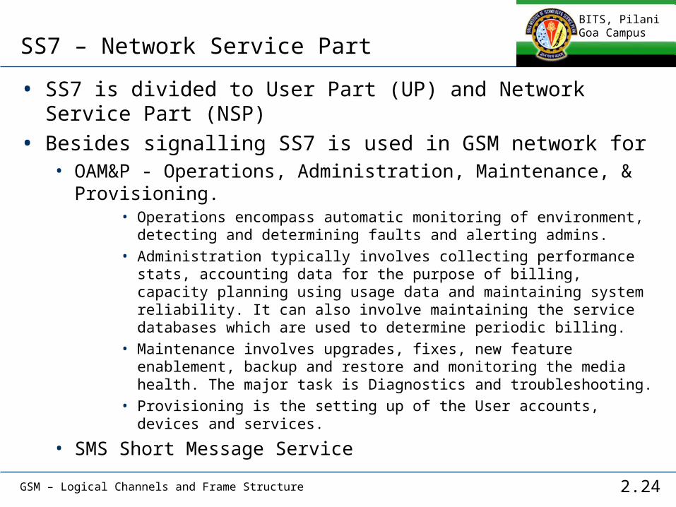
• Some of the GSM/UMTS Core Switched interfaces in the Mobile Switching Center (MSC) transported over SS7 include the following:
• B -> VLR (uses MAP/B). Most MSCs are associated with a Visitor Location Register (VLR), making the B interface "internal".
• C -> HLR (uses MAP/C) Messages between MSC to HLR handled by C Interface
• D -> HLR (uses MAP/D) for attaching to the Circuit Switched network and location update
• E -> MSC (uses MAP/E) for inter-MSC handover• F -> EIR (uses MAP/F) for equipment identity check• H -> SMS-G (uses MAP/H) for Short Message Service (SMS)


![TS-3GA-32.450(Rel10)v10.1.0 Telecommunication …Rel... · 5.作成専門委員会 [Working Group] ... Performance measurements - GSM". ... E.g. a success rate KPI’s logical](https://img.dokumen.tips/doc/110x75/5aad7db27f8b9a59658e5ee8/ts-3ga-32450rel10v1010-telecommunication-rel5.jpg)