Embed Size (px)
Citation preview

8/8/2019 Gsm Concepts
http://slidepdf.com/reader/full/gsm-concepts 1/54
GSM Concepts

8/8/2019 Gsm Concepts
http://slidepdf.com/reader/full/gsm-concepts 2/54
2
GSM
Various subsystems1. Network Subsystem includes the equipments
and functions related to end-to-end call.
2. Radio Subsystem includes the equipments andfunctions related to the management of theconnections on the radio path.
3. Operations and Maintenance subsystemincludes the operation and maintenance of GSMequipment for the radio and network interface.

8/8/2019 Gsm Concepts
http://slidepdf.com/reader/full/gsm-concepts 3/54
3
Network Architecture
BT
S
MSC VLR
HLR
PSTNISDN
Data
Networks
Air interface
OSS
B
T
S
B
T
S
MSC VLR
BSC
BSC

8/8/2019 Gsm Concepts
http://slidepdf.com/reader/full/gsm-concepts 4/54
4
GSM
Interfaces AUC
MSC
BSC
BTS
MS
OMC
ISDN
PSPDN
CSPDN
PSTN
PLMN A - Interface
BSS
A-bit interface Access to different
services
Base station system
Information transmission
Call connections and information transmission
SS
X.25
VLR EIRHLR
X.25

8/8/2019 Gsm Concepts
http://slidepdf.com/reader/full/gsm-concepts 5/54
5
GSM
Network Structure
GSM Service Area
PLMN Service Area MSC Service Area
Location Area Cells

8/8/2019 Gsm Concepts
http://slidepdf.com/reader/full/gsm-concepts 6/54
6
GSMPLMN Service Area
V
MSC
MSC
MSC
MSC
VLR
VLR
VLR
I II
IVIII
I
VLR

8/8/2019 Gsm Concepts
http://slidepdf.com/reader/full/gsm-concepts 7/54
7
GSMMSC Service Area
MSC
VLR LA1
LA2
LA3
LA6LA4 LA5

8/8/2019 Gsm Concepts
http://slidepdf.com/reader/full/gsm-concepts 8/54
8
GSMCells
MSC
VLR LA1
LA2
LA3
LA6LA4 LA5
C1C2 C3
C6 C5C4
C=CELL

8/8/2019 Gsm Concepts
http://slidepdf.com/reader/full/gsm-concepts 9/54
9
GSMRelation between areas in GSM
Cell
( Area served by one BTS )
Location Area
PLMN Service Area
( one per operator )
MSC Service Area
GSM Service Area

8/8/2019 Gsm Concepts
http://slidepdf.com/reader/full/gsm-concepts 10/54
10
GSM
LA Coding
MCC
LAI
LACMNC
3 digit 3 digit 2 Octets

8/8/2019 Gsm Concepts
http://slidepdf.com/reader/full/gsm-concepts 11/54
11
GSMMobile Station
Portable, vehicle mounted, hand held MS identified by unique IMEI
Shall display at least last ten received, dialledand missed calls
Minimum talk time of 1hr 30 min. andstandby time of 80 hrs

8/8/2019 Gsm Concepts
http://slidepdf.com/reader/full/gsm-concepts 12/54
12
GSM
Functions of Mobile Station Voice and data transmission
Frequency and time synchronization
Monitoring of power and signal quality of thesurrounding cells for optimum handover
Provision of location updates even duringinactive state
Equalization of multi path distortions
160 characters long SMS

8/8/2019 Gsm Concepts
http://slidepdf.com/reader/full/gsm-concepts 13/54
13
GSM
Mobile Station - Power LevelsPower
Class
Max. Peak
Power
Tolerance (dB)
Normal Extreme
1 20W
(43 dBm)
+/- 2 +/- 2.5
2 8W
(39 dBm)
+/- 2 +/- 2.5
3 5W
(37 dBm)
+/- 2 +/- 2.5
4 2W
(33 dBm)
+/- 2 +/- 2.5
5 0.8W
(29 dBm)
+/- 2 +/- 2.5

8/8/2019 Gsm Concepts
http://slidepdf.com/reader/full/gsm-concepts 14/54
14
GSM
SIM Card
SIM Module
Unique Subscribers ID IMSI and ISDN PIN
Key Ki, Kc and A3,A5 and A8 algorithms
SIM has CPU, ROM, RAM and EPROM

8/8/2019 Gsm Concepts
http://slidepdf.com/reader/full/gsm-concepts 15/54
15
GSM
Mobile Identification Numbers IMEI
MSISDN
IMSI
TMSI
MSRN
8/8/2019 Gsm Concepts
http://slidepdf.com/reader/full/gsm-concepts 16/54
16
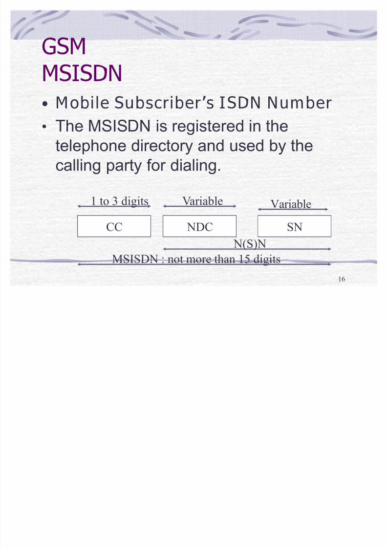
GSM
MSISDN Mobile Subscribers ISDN Number
The MSISDN is registered in the
telephone directory and used by the
calling party for dialing.
CC NDC SN
1 to 3 digits Variable Variable
MSISDN : not more than 15 digits
N(S)N

8/8/2019 Gsm Concepts
http://slidepdf.com/reader/full/gsm-concepts 17/54
17
GSM
IMSI International mobile
subscribers Identity The IMSI is an unique identity which is
used internationally and used within thenetwork to identify the mobile
subscribers. The IMSI is stored on thesubscriber identity module (SIM), theHLR, VLR and AC database.

8/8/2019 Gsm Concepts
http://slidepdf.com/reader/full/gsm-concepts 18/54
18
GSM
IMSI
MCC MNC MSIN
3 digits 3 digits Not more than 9 digits
NMSI
IMSI : Not more than 15 digits

8/8/2019 Gsm Concepts
http://slidepdf.com/reader/full/gsm-concepts 19/54
19
GSM
TMSI Temporary Mobile subscribers
Identity The TMSI is an identity whichguarantees the integrity of the mobilesubscribers on the radio interface. The
VLR assigns a TMSI to each mobilesubscribers entering the VLR area.

8/8/2019 Gsm Concepts
http://slidepdf.com/reader/full/gsm-concepts 20/54
20
MSRN ± Mobile Subscriber Roaming Number
It is a temporary number used for routing the call to MS.
Format : MSRN = CC + NDC + SN
CC = Country Code
NDC = Network Destination Code
For example for Patna MSC in IMPCS network MSRN looks
like 91 98750 00100.
SN = Subscriber Number

8/8/2019 Gsm Concepts
http://slidepdf.com/reader/full/gsm-concepts 21/54
21
PSTN GMSC
HLR
MSC VLR
MSISDN
1
MSISDN2
IMSI
3
IMSI MSRN4
MSRN
5
MSRN 6
MSRN
7

8/8/2019 Gsm Concepts
http://slidepdf.com/reader/full/gsm-concepts 22/54
22
GSM
MSRNMobile Station Roaming
Number
The MSRN is used in the GMSC to set up aconnection to the visited MSC/VLR.

8/8/2019 Gsm Concepts
http://slidepdf.com/reader/full/gsm-concepts 23/54
23
GSM
IMEI International Mobile Equipment
Identity
The IMEI is an unique code allocated to eachmobile equipment. It is checked in the EIR.
IMEI check
y
White List y Grey List
y Black List

8/8/2019 Gsm Concepts
http://slidepdf.com/reader/full/gsm-concepts 24/54
24
RADIO SUB SYSTEM (RSS)RADIO SUB SYSTEM (RSS)
n BTS n BTS
BSC
BSC
BSC
MSC/VLR
RSS

8/8/2019 Gsm Concepts
http://slidepdf.com/reader/full/gsm-concepts 25/54
25
GSMFUNCTION OF BTS -I
Encodes, encrypts, multiplexes, modulatesand feeds the RF signals to the antenna
Transcoding and rate adaption Functionality
Time and frequency synchronisation signalstransmission.
Communication on full or half rate channel
11 power classes from .01 watts (Micro cell)
to 320 watts (Umbrella cell)

8/8/2019 Gsm Concepts
http://slidepdf.com/reader/full/gsm-concepts 26/54
26
GSMFUNCTION OF BTS -II
Frequency hopping
Random access detection
Uplink radio channel measurements
BTS mainly consists of a set of transceivers(TRX)

8/8/2019 Gsm Concepts
http://slidepdf.com/reader/full/gsm-concepts 27/54
27
GSMFUNCTIONS OF BSC-I
Radio resource management
Assigns the frequency and timeslots for allMSs in its area.
Inter-cell handover
Power control

8/8/2019 Gsm Concepts
http://slidepdf.com/reader/full/gsm-concepts 28/54
28
GSMFUNCTIONS OF BSC-II
Time delay measurement of the receivedsignals from MS with respect to BTS clock.
Performs traffic concentration to reduce thenumber of lines from BSC to MSC.
Provide interface TCP/IP X.25 to the OMS
8/8/2019 Gsm Concepts
http://slidepdf.com/reader/full/gsm-concepts 29/54
29
GSMFUNCTIONS OF BSC-III
BSC performs call processing
TRAU are generally located at the site of MSC.
BSC- BTS configurations as per requirement.
Data from OMC and can be down loaded to
BSC

8/8/2019 Gsm Concepts
http://slidepdf.com/reader/full/gsm-concepts 30/54
30
GSM
MSC-BSS Configurations
BTSBTS
BTS
BTS BTS
BTS
A-bis
BSC
BSS
Configuration -6 Multi - cell site =multi--BTS site
Many single
cell sites
BSS
MSC
BTS
A A
A
Single - cell site
Configuration -1
Multi - cell site (sector CellsConfiguration -5
MCC: Mobile Switching Centre
BSS: Base Station System
BSC: Base Station Controller
BTS: Base Transceiver Station
A-bis

8/8/2019 Gsm Concepts
http://slidepdf.com/reader/full/gsm-concepts 31/54
31
GSM
Transcoder ConfigurationsBTS TRAU BSC MSCTo MS To fixed
networks
BSC TRAUBTS MSCTo MS To fixednetworks
TRAU MSCBTS BSCTo MS To fixednetworks
RF Air Interface
A-bis
Interface
AInterface
13 kbps encoded voice/ 12 kbps data16 kbps transmission
64 kbps transmission
Transcoder (XC) configurations
8/8/2019 Gsm Concepts
http://slidepdf.com/reader/full/gsm-concepts 32/54
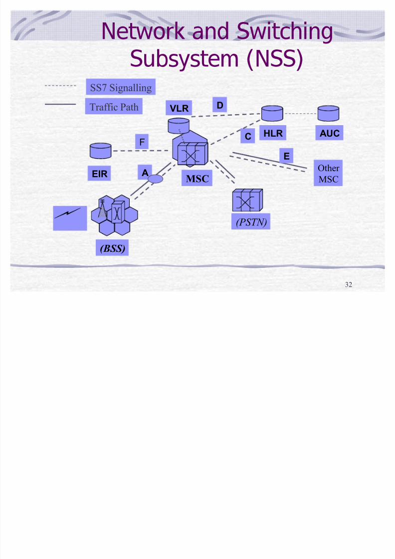
32
Network and Switching
Subsystem (NSS)
MSC
(PSTN)
VLR
HLR AUC
EIR
D
C
SS7 Signalling
Traffic Path
F
( BSS)
A
E
Other
MSC

8/8/2019 Gsm Concepts
http://slidepdf.com/reader/full/gsm-concepts 33/54
33
GSMMSC ( MOBILE SWITCHING CENTRE)
Manages communication between GSM &
other network
Call setup functions, basic switching are done
MSC takes into account the RR allocation in
addition to normal exchange functions
MSC does gateway function while its customers
roams to other network by using HLR /VLR

8/8/2019 Gsm Concepts
http://slidepdf.com/reader/full/gsm-concepts 34/54
34
GSM
MSC Functions - I Paging, specifically call handling
Dynamic allocation of resources in coordination withBSS
± MSC decides what type of channel and when to beused
± BSS decides channel identity and radio parameters
Location registration
Handover management Billing for all subscribers based in its area
Reallocation of frequencies to BTSs in its area to meetheavy demands

8/8/2019 Gsm Concepts
http://slidepdf.com/reader/full/gsm-concepts 35/54
35
GSM
MSC Functions - II Echo canceller operation control
Signaling interface to databases like HLR, VLR.
Gateway to SMS between SMS centers andsubscribers
Handle interworking function while working asGMSC

8/8/2019 Gsm Concepts
http://slidepdf.com/reader/full/gsm-concepts 36/54
36
GSM VISITOR LOCATION REGISTER (VLR)-I
It controls those mobiles roaming in its area.
Main task of VLR is to reduce the number ofqueries to HLR
One VLR may be incharge of one or more LA.
VLR is a database and gets updated whenevera new MS enters its area, by HLR database.

8/8/2019 Gsm Concepts
http://slidepdf.com/reader/full/gsm-concepts 37/54
37
GSM VISITOR LOCATION REGISTER (VLR)-II
Authentication along with HLR and AUC.
Relays ciphering key from HLR to BSS.
VLR is responsible for assigning TMSIand can be periodically changed to
secure the subscribers identity.
IMSI detach and attach operation

8/8/2019 Gsm Concepts
http://slidepdf.com/reader/full/gsm-concepts 38/54
38
GSMData in VLR IMSI & TMSI
MSISDN
MSRN.
Location Area
Supplementary service parameters
MS category Authentication Key

8/8/2019 Gsm Concepts
http://slidepdf.com/reader/full/gsm-concepts 39/54
39
GSM
Home Location Register(HLR)-I
Reference store for subscribers parameters,numbers, authentication & Encryption values.
Current subscriber status and associated VLR.
one PLMN may contain one or several HLR.
Logically there is only one HLR per PLMN.

8/8/2019 Gsm Concepts
http://slidepdf.com/reader/full/gsm-concepts 40/54
40
GSM
Home Location Register(HLR)-II Permanent data in HLR Data stored is changed only by man-machine.
IMSI, MS-ISDN number.
Category of MS ( whether pay phone or not )
Roaming restriction ( allowed or not ).
Supplementary services like call forwarding

8/8/2019 Gsm Concepts
http://slidepdf.com/reader/full/gsm-concepts 41/54
41
GSM
Home Location Register(HLR)-III Temporary data in HLR The data changes from call to call & is dynamic
MSRN
RAND /SRES and Kc
VLR address , MSC address.
Messages waiting data used for SMS

8/8/2019 Gsm Concepts
http://slidepdf.com/reader/full/gsm-concepts 42/54
42
GSM AUTHENTICATION CENTRE (AUC )-I
Protect against intruders in air interface
Authentication and ciphering key arestored securely in this data base.
Ki Kc keys are never transmitted to MSon air

8/8/2019 Gsm Concepts
http://slidepdf.com/reader/full/gsm-concepts 43/54
43
GSM AUTHENTICATION CENTRE (AUC )-II
Only calculated response are sent overthe air interface
Cipher key is transmitted over SS7 linkbetween home HLR and AUC
Random key and cipher key changesrandomly with each phone call
AUC is a separate entity and physicallyincluded in HLR

8/8/2019 Gsm Concepts
http://slidepdf.com/reader/full/gsm-concepts 44/54
44
GSMEQUIPMENT IDENTITY REGISTER ( EIR )
This data base stores IMEI for all registeredmobile equipments and is unique to every ME.
Only one EIR per PLMN.
White list : IMEI, assigned to valid ME.
Black list : IMEI reported stolen Gray list : IMEI having problems like faulty
software, wrong make of equipment etc.

8/8/2019 Gsm Concepts
http://slidepdf.com/reader/full/gsm-concepts 45/54
45
Architecture For Mobile Originated Call
BSS-AMS
VLR-A
MSC-A
PLMN
A- I/F
Signaling
IAM ( ISUP )Radio I/F
Signaling
Send Info
for o/g call
/ ACK
A hit t F M bil T i t d C ll

8/8/2019 Gsm Concepts
http://slidepdf.com/reader/full/gsm-concepts 46/54
46
Architecture For Mobile Terminated Call
GMSC- B BSS-B
MS
VLR-B
MSC-B
VISITING PLMN
A- Interface
Air Interface
HLR-B
IAM ( ISUP )

8/8/2019 Gsm Concepts
http://slidepdf.com/reader/full/gsm-concepts 47/54
47
The centralized operation of the various units inthe system and functions needed to maintain thesubsystems.
Dynamic monitoring and controlling of thenetwork
Separate OMC-S and OMC-R for NSS and RSS
Operations and Maintenance Centre
OMC
Operations and Maintenance Centre
OMC

8/8/2019 Gsm Concepts
http://slidepdf.com/reader/full/gsm-concepts 48/54
48
functions
-O&M data function
-Configuration management
--Fault report and alarm handling
-Performance supervision/management
-Storage of system software and data
-Support GUI for operation and Maintenance
-Collect and store data for a minimum 1 year.
Functions Of OMCFunctions Of OMC
8/8/2019 Gsm Concepts
http://slidepdf.com/reader/full/gsm-concepts 49/54

8/8/2019 Gsm Concepts
http://slidepdf.com/reader/full/gsm-concepts 50/54
50
GSM
Encryption Process
Encryption
ProcessKEY
Plain Text
Cipher-text
GSM

8/8/2019 Gsm Concepts
http://slidepdf.com/reader/full/gsm-concepts 51/54
51
GSMGeneric Authentication
Process
A3 A3
Ki KiRAND
RAND
CompareSRES
SRES
Response
IMSIIMSI
Yes/No
Radio Path

8/8/2019 Gsm Concepts
http://slidepdf.com/reader/full/gsm-concepts 52/54
52
AUTHENTICATION & ENCRIPTION AUC
Database
Generation
of Random Number
RANDRAND
IMSI1
IMSI3
IMSI2
ki1
ki2
ki3
RANDSRESKc
Algorithm for Ciphering
A8
Algorithm for
Authentication
A3
Kc
64 bits
SRES32 bits
HLR

8/8/2019 Gsm Concepts
http://slidepdf.com/reader/full/gsm-concepts 53/54
53
AUTHENTICATION & ENCRIPTION
HLR SRES=
SRESc
A3Sim
Card
Key Pad
A8
Store
Kc
AccessGranted
RAND
Yes
MSC/VLR RAND Ki
SRESc
(128)
SRES
(32)
Kc
Cipher
Key Transfer Kc to
BTS
no

8/8/2019 Gsm Concepts
http://slidepdf.com/reader/full/gsm-concepts 54/54
54
THANK THANKS !
ALT CENTRE
ALTTC
![Sieci GSM - cygnus.tele.pw.edu.plcygnus.tele.pw.edu.pl/~zkotulsk/seminarium/prezentacjaGSM.pdfSystem GSM 400 GSM 850 GSM 900 GSM 1800 GSM 1900 Uplink [MHz] 450.4 - 457.6 ... Odpowiedź](https://img.dokumen.tips/doc/110x75/5ae024237f8b9a97518cdd37/sieci-gsm-zkotulskseminariumprezentacjagsmpdfsystem-gsm-400-gsm-850-gsm-900.jpg)