Embed Size (px)
Citation preview

GSftwPti I t:rc
OPERATION MANUAL FOR
HACKSAW MACHINE MODEL G7016
'• .. Capacity 160mm Serial No ~:;,/
ESAWPH-716
CONTENTS
I. General View ··· ··· ·;·· ··· ··· ··· ··· ··· ··· ··· ··· ··· ··· ··· ··· ··· ··· ··· ··· ··· ··· 1
II. Technical Specifications ··· ··· ··· ··· ··· ··· ··· ··· ··· ··· ··· ··· ··· ··· ··· ··· 1
ITT. Application ... -... ··· ··· ··· ··· ··· ··· ··· ··· ··· ··· •·· ··· ··· ··· ··· ··· •·· ··· ·•• ·•• 2
IV. Construction···································································· 2
·y. Transmission_ System ··· ··· ·· · ··· ... ··· ··· ··· ··~ •·· ··· ··· ·_·· ··· ··· ·•· ··· ··• 3
1. Transmission diagram ••• •·· •·• •· · ·•• ••• ••• •·• ·•• ••• ·•· ••• .~. ···-··· ••• 3
2. Main driv-e ••• ••• ••• ••• · •·. ••• •• • ·~· ·· · • •• • •· · ·• · · • · ·•· • • ·•• · • • ... ••• ••• ••• 3
3. Feeding········•······ .......... · • ···· ··· ··· ··· ··• .... ··· ··· ··· · ·· ··· ···-··-····-··· 4
4. Withdrawal of saw blade· .. ·•······· ... ··· ............ ·•• ........ .- 4
VI. Electric Equipme11t ............................... ··· ··· ··• ··• ···•·• ··· •·• •·· •·· ••· 4
1. Electrical circuit diagram ........................... · .........•••.•..••••••• 4
2. Desc~iption ··· ··· ··· ~-·· '0 •••••• • •• ••••••• •••••••• •••• ••• ••• ••• ••• ••• ••• ••••••• •••• .5 3. Parts. list .................................................................. 5
VII. Hydraulic SJ·stem ··· ...... , ··· ··· ··· ··· ··· ··· ··· ··· ··· ··· ··· .... ··· ···•·· ··· ··· 5
VIII. Cooling System ··· ............................................................................. 7
IX. <;::lamping Dev.ice ···· ···· ···· ···· ···· ···· ···· ···· ···• ···· ···· ... ~ ···· ··-·· •··· ···· ···· ···· ···i · ·· 7
X. Handling and Installation ........................ ~ ................. , ................... 7
XI. Lubrication ········ ···· ············ ············ ···· ···· ········ ···· ················ ···· ···· ···· ···· ·· · 7
-XII. Operation and Adjustment ............................................................ ··· 8

Hacksaw Machine Model ·G701-6
Certificate of Conformity
The machine is. qualified to leave factory with its
precision verified.
Ex factory N~mber: :>o/0 >>'/
Examiner:

I. General View
4
1. Stock s.top a\tachm&nt 2. Machine bep . . 3. Vice
·.5 ·-~~
6
4. Saw frame 5. Saw arm 6.· Hydr.ciulic pump·
7. Supp0 rt 8. Coolant pump. ·9 •. Electric :equipment
Il . Techilkal · Specifications
.l. Capacity:
Ro.und bar diaqieter.
Square bar. side
Other rolled steel
I60mm. 160mm. - .. No. 16
~1-

2. Hacksaw blade
3. Transmission:
(a) Reciprocating motion:
( 1) No. of strokes
(2 > Average linear speed
<3) Blade stroke
. (p) Raising and descencing motions:
350x 2-Sxl. 25mm'
85/min.
l 7;..,31rn/min.
100--180mm .
( 1) Manual blade lifting with upper -limiter.
(2) Automatic f ~eding witb lower limiter.
<3) Raising and withdrawal for .blade by hydraulic system.
4. Electric motor: Model C07124, (A06334) 220V (380V), 370W 50Hz,
1400rpm.
5. Coolant pump: CB-K 1.21 Gear pump.
6. Dimensions: 914X380X696mm
7. Net weight: 160kg:
III. Appiication
This machine is used for cold-cutting of round, square or other sections
metals of up to 160mm. in diameter or side. The ma.chine adopts single
phase electricity for users' convenience. Since the machine is ~simple in
construction, light in weight anb easy in operc.tion, it is especially suitable
for the frequent moving :needed.
IV. Construction
The reciprocation motion of the blade is imparted by an elebtric
·motor through belt and gears. The feeding is given by tbe gravity of saw
frame and saw arm. For t~e composition of the machine, ref er . to the
chapter I "General view" . <fig. 1)
-2-
V, Transmission System
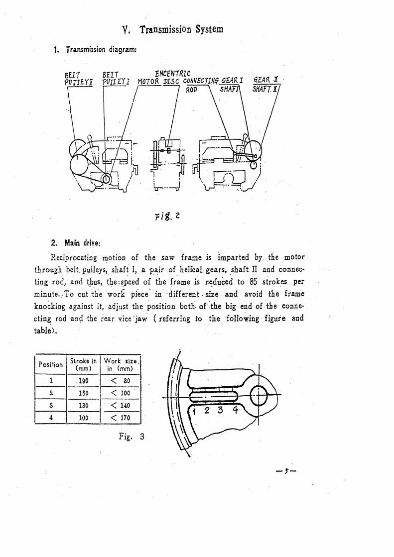
1. Transmission diagram:
BfI1 PT!JIEYI
.\
2. Main drive:
-- M+ ·.~ i-1 I . ~ •• -J
rig. z
Reciprocatin.g ~otion of the saw frame is imparted· by .. the motor·.
through belt. p·ulleys, shaft I, a ·pair of helfoaL gears, shaft II and connec·
ting rod, ~n:d :~~us, "_t~e:~p.ee.d o(the fr~me iS i:~du_ced to 85 °Strok.es per
minute~ .. To .cu.t :the wo.rk piece·· in ·different: size and avoid· the frame
knocking against it, adjust the position both- of :the big end or"tbe conne-. · . .
ctin~. rod ·an~ the rear vice ·ja~ (referring to. the. ·foHowlng · figui:e and
table>.
I . Work size. PosT Stroke in
1 ion (mm) in (mm)
1 .19"0 <. 80
2 160 I < 100 I
~ 130 I ·< 140
100 I < 170
Fig. ·3
_,._

3. ·Feeding:
The Feeding is ~arried out by tbe gravity of saw· _frame and saw arm.
For each feeding, oil is discharged to the. oil reservoir through a small
hole on the ~ide of the plunger pump body.
4. Wlthdqa '."~I·· of. hacksa v/ blade: . .
Duirng return stroke, the frame and arm are raised hydraulically by.
the plunge.r pump, which is actuated by the en.centric bisc on shaft II
through a rocker· iever.
VI..· Electric Equipment
t ." Electric~t·circuit dia-gram:
-.f.-
SlNGI.E PHASE CIRCUIT
SU!~L! PHASE CJP.CUIT
A07!24
1f\I- PHASE C!RCTJ!T
n-'l . . · : b/ ..... : __ ~OT· t<EA.DY gy VSER HIHSC:Lr
'·~·_4T_~i9""' ~CJ . t9~f I· --~~- L.Ji_filj;<l\ -~-I I \l}I I ----------------=::::-----. ?:::..::! .H' ~~i l lCJ ~ --.ii (®) ,. 1"}.-"
?E _ffiD •.:.O 71 '-'"'t //I V::.J 570 w

2. Description: This _machine works Oil :a power of single phas~ A •. c. ·22ov. 50Hz.
Currint is ~aken in from the socket through A: C .. contactor (CJY~ ~OA·~r<?l button CAT,AQ). to th·e motor. When a .tri-pha.se power is adopted,· t~~ motor should be replaced_ with a tri-phase one. The J11achine is pro;;ided.
with a protectio~ device ·for oved9ad and short circuit .. Op.er~tion proc
_edure as follows: Raise the saw. arm, depress the button AT, so make th~ niotor ·and
the ·coolant pump begins working. While the work piece _is cut up,· the
but~on XK will _be de_pressed by .the limit scr~w on th~ support .rod, . so
the limit switch turned off and the -machine stopped itself. When. the fr~me is in its lowest position, inching can be done by (JepreSsing the ·shut bu.jto.~.·
3. Part List:
' .. - ,----__,--,-·-M-0-D-EL-" .-. -,- SP~·FICATION ... ·_._···.·.·.QTY.. ., SYNBOLI NAME
I . 1-Phase.! 3-phase I I-phase" I 3-phase l-phasel3 .. phasej ., : I I I I j D ! Jvfotor · ' I C07124 ! ~.t\.071241 370W: 501-Iz, 1400rpm. . 1 '1----1 c 1 · CJlO-'"" A f CQil voltage Coil vo~tage 1 I . -_~j A contactor L o 1 __ ?_2_o_v __ . 380v · !-----' Ii\. T AQI P h b t+ I LA20 2H - 1 I us - u .on I I • -,
I Limit switch I •' I
I
I XK 1 I I . -· I RL 1· Fus~ cartridge lOA 3 A· 2 3
I , __
BLX i I I 3 I Fuse case · I 2 !
. '
VU. Hydraulic· System
The Hydraulic system is located at the rear part of the machine bed. . ' . . .
When thh encentric disc on shast II rotates. the rocker lever deoresses . . . ~Q.e plunger to close the throttle hoie first, then supplies oil to its main
oil cylinder, thus raising the sa'\v arm and withdrawing the blade. The
amount of the blade raising can be varied by adjusting the bolt on the

rear end of the rocker lever. In order to advoid jammed, a definite extent
of compression for the plunger and spring should be retained after adjus·
tment. When checking the machine accuracy, turn down the boit az" on
the pump body, so as to control the frame lowering speed and make it
descend slowly. When cutting is carried out, turn down the adjusting bolt
to raise. the pressure of the whole hydraulic system to assure the cutting
speed.
Under the normal conditions, oil is replaced every three months.
Adjustment of the relieve: The bolt u2J: is used for regulating the
spring "3" , it makes the hydraulic syscem maintain a definite pressure
and range for blade raising during return stroke and prevent damage from
overload.
'When adjusting the valve, screw out the fastening bolt "1 'J first, ti.rm
dow~ or turn up for raising or lowering the pressure and then fasten
the bolt. PLUNGER 1'1.S TON
DIAtrRAM
. ADJUSTING SCREW P.OCKER
i-IYJJPJ.ifL IC IRAN.SMISS!ON :DIA~i'iAN -6-

VIII. Cooling System
The CB- .l .2J gear pump is used for this system, it .mounted at the
Ief t of the machine bed. The cooling pipe is fixed on the mach_ine bed. The
water tank is provided with isolating plates cleaning hole, and it has to
be rinsed frequently together with the strainer. The rust-preventive liquid
is recommended as a coolant for cutting and it shonld be replaced twice
weekly.
lX. Clamping Device
A Jlc.t jc.w vice with inner taper is served as a clamping device. A. vertical
compO'nent force is resulted from it while clamping. The - front vice is
provided with scale. The work of a certain size can be cut slantwise up
to 45 c. f.-foving the rear vice position, the job size slant cutting can be
· extei1ded arid the local wear on biade also may be reduced. Adjust the
rear vic-2 to a proper position to prevent the pallets f ro::n striking when
cutting the lilrg.::r works.
X. Handling a·nd· Inst;tllation
The net weight of the machine is lGOkg. When it is hoisted, to pad
with wood blocks below both sides of the rear bracket. There are two
wheels under the rea:·. bracket, only by lifting the fro11t of the machine bed
XI. Lubrication
Refer to the following chart and table for lubricating points and intervals:
-i-

1 2 3 2 5 "6 .
IN . I I
~ o., 1n1· Jubricating 1 Interval f" · j · · Lubr!c.atin9 Point
method Lubricant r .
1-~1---- . i -~oa.cl~.iie oil lrwice every shift I 1 · j Bearing o! shaft T oil :!\Jan;.:al
I 1, cup.
2 I Bearing of shaft II. oil cup .. . - do- I -do-I
I 3 I Encentric disc, face - do- I - do·-.. I
I Guideways, oil i
4 cup " -do- I · - do -I I
5 ·Connecting rod pin, small end, " - do- I - do-
oil hole l 6 Connecting rod bearing
Ca. base I At time of I
"' grease No. 11 overhaul ..
XII. Operation and Adjustment
·A. Preparation for operating
1. Full the oil cylinder with machine oil No. 20 up to the level.
2. Add coolant into the .water tank up to the sight glass.
3 .. Apply oil to every lubrication point.
4. Lower down the arm. to a position where the work piece is to be
-8-

cut off and make sure the limit screw on the support handle press
down the limit switch while the-work p_iece is cut .off ... 5. Adjust the stroke according to the work size.
6. Turn on the main! B. Adjustment and Cautions.:
1. For cutting solid. round and square bars, ~et the fixing. screw: on the
encentric disc to coincide 'with the red · markline on the ·retainer. . . . . . . .
Mount the sawblace with its te'eth towards the .. front. ·when the
hollow dr thin ·wall workpiece is .~ut, the blade has to be mounted
oppositely, arid make sure the screw coincide with the 'blue markline ..
2. When the guideways have been worn to a certain extent; adjust
the gibs and scrape both upper and lower pallets to -maintain ·
prper clearan~e.
. INDICATION ECCcN1RIC §_HA_'"F..,._1 _l~_D 1_AR_K~~\~·_NEB._
7_p_1s_~.- 7
\ I
REAR··~- FRONT
WORN PARTS LIST
Serial Mo. I Chart No.1 Name Material Oty. · Remark
l 227 Upper liner HT20-4QI~ Shown in fig •. 1
-----~--
2 2 3 2 I Lower Hner I HT 20-40 I 2 I Shown in fig. 1

~I {!'ll
~·
I j
~i_~.r::.:F===::::==t::~~:r~. ~.O_'o_.o·' i
Oll <fROCVE THREAV
-10-
L_ A
~ o!o.oc=>;
CHAMFE.R. f X-4 5 •
L-1 ·::-i ··"¢.,.-!7 .i.1t.;...r1 V 1 I C.(\
A ! vEP1H
L. A .
· -'l"C.?", 1HE c i rli-f\ ....
, :11 · - ... ~

1
2
PACKING LIST
ARTICLE: Hacksaw Machine Model G7016 Max.Cutting diameter l60mm.
Serial No.
Case No.
Overall dimensions (1 xbxh)cm 104X43X84
Net weight 160kg
Gross weight 190kg
r Name ~ Model of specification
vise G701.6-500. On the machine
3 Colling equipment CB K 1.2J Gear pump, on the machine
4 Chip Container
5 Stock stop Attachment
6 Hacksaw blade
7 Technical Documents:
Operation Manual
Test Certificate
Packing List
G70J6-I22
G7o16-116/117
350 x2s Xi. 25(14"' )mm
Quantity
1 set
1 set
1 set
1 pice
1 set
1 pica
1 copy
1 copy
1 copy