Embed Size (px)
Citation preview

Vertical MultistageCentrifugal Pumps
50 Hz
CR, CRN
TM
01 2
151
1298

2
General DataCR, CRN Performance Range Page 3Product Range Page 4Overview of Applications Page 5CR 2, CR 4, CR 8 and CR 16 Page 6CR 32, CR 45, CR 64 and CR 90 Page 7CRN 2, CRN 4, CRN 8 and CRN 16 Page 8CRN 32, CRN 45, CRN 64 Page 9CRN-S Page 10CRN-SF Page 11Pumped Liquids Page 12Motor Page 12Shaft Seals Page 12Maximum Operating Pressure Page 13Maximum Inlet Pressure Page 13Type Key Page 14Codes Page 14Performance Curves Page 15Selection of CR, CRN pumps Page 16List of Pump Liquids Page 64List - continued Page 65
Performance Curves/Technical DataCR 2 Page 18CRN 2 Page 20CRN 2-S Page 22CRN 2-SF Page 24CR 4 Page 26CRN 4 Page 28CRN 4-S Page 30CRN 4-SF Page 32CR 8 Page 34CRN 8 Page 36CRN 8-S Page 38CRN 8-SF Page 40CR 16 Page 42CRN 16 Page 44CRN 16-S Page 46CRN 16-SF Page 48CR 32 Page 50CRN 32 Page 52CR 45 Page 54CRN 45 Page 56CR 64 Page 58CRN 64 Page 60CR 90 Page 62
AccessoriesAccessories Page 66
Contents
3
General Data Vertical Multistage Centrifugal Pumps
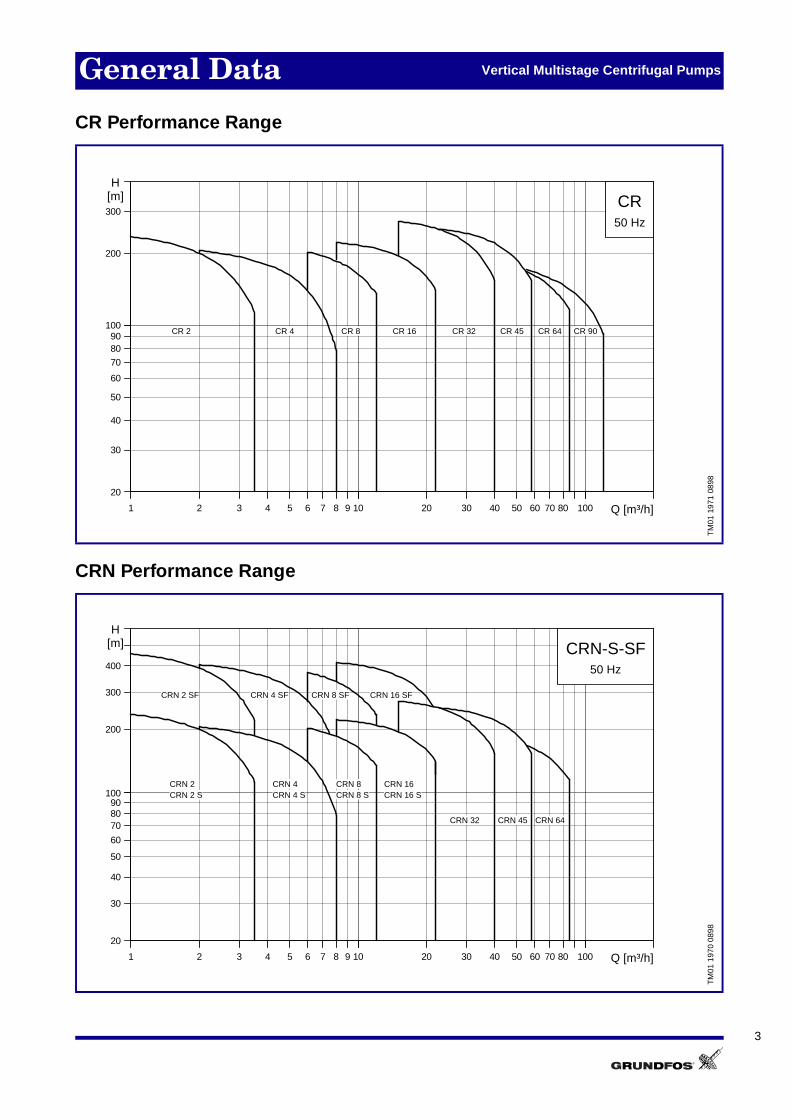
CR Performance Range
CRN Performance Range
TM
01 1
971
0898
1 2 3 4 5 6 7 8 9 1010 20 30 40 50 60 70 80 100100 Q [m³/h]
20
30
40
50
60
70
8090
100100
200
300
H[m] CR
50 Hz
CR 90CR 64CR 45 CR 32CR 16CR 8CR 4CR 2
TM
01 1
970
0898
1 2 3 4 5 6 7 8 9 1010 20 30 40 50 60 70 80 100100 Q [m³/h]
20
30
40
50
60
708090
100100
200
300
400
H[m] CRN-S-SF
50 Hz
CRN 16 SFCRN 8 SFCRN 4 SFCRN 2 SF
CRN 64CRN 45CRN 32
CRN 16CRN 8CRN 4CRN 2CRN 2 S CRN 4 S CRN 8 S CRN 16 S

4
General Data Vertical Multistage Centrifugal Pump
Product Range
� depending on temperature, see page 13 �� depending on shaft seal, see page 12
Description CR 2 CR 4 CR 8 CR 16 CR 32 CR 45 CR 64 CR 90
Range
Nominal flow rate [m3/h] 2 4 8 16 32 45 64 90
Flow range [m3/h] 1 - 3.5 2 - 8 6 - 12 8 - 22 15 - 40 22 - 60 30 - 85 50 - 120
Max. pressure [bar]� 45 44 42 44 28 26 20 19
Motor power [kW] 0.37 - 3 0.37 - 4 0.37 - 7.5 2.2 - 15 1.5 - 30 3 - 37 4 - 37 5.5 - 45
Temperature range [°C]�� –20 to +120 –20 to +120 –20 to +120 –20 to +120 –30 to +150 –30 to +150 –30 to +150 –30 to +150
Max. efficiency [%] 48 59 64 70 78 79 80 81
Version
CR ● ● ● ● ● ● ● ●
CRN ● ● ● ● ● ● ●
CRN-S ● ● ● ●
CRN-SF ● ● ● ●
Material Variant
CR: Cast iron GG20/Stainless Steel AISI 304/DIN 1.4301
● ● ● ●
CR: Cast iron GGG50/Stainless SteelAISI 304/DIN 1.4301
● ● ● ●
CRN: Stainless steelAISI 316/DIN 1.4401 ● ● ● ● ● ● ●
CR Pipe Connection
BSP (Oval flange) 1" 1¼" 1½" and 2"
DIN flange DN25 DN32 DN40 DN50
Flexible DIN flange DN65 DN80 DN100 DN100
DIN flange on request DN80 DN100 DN125 DN125
CRN Pipe Connection
DIN flange DN25 DN32 DN40 DN50
Flexible DIN flange DN65 DN80 DN100
DIN flange on request DN80 DN100 DN125
PJE coupling ● ● ● ●
Clamp coupling ● ● ● ●
Union (+GF+) ● ● ● ●
Shaft Seal
DIN standard seal ● ● ● ●
DIN Cartridge seal ● ● ● ●
Long coupling (>7,5 kW) ● ● ● ●
Hybrid seal surface �� ● ● ● ●
Miscellaneous Features
Prepared for sensors ● ● ● ●
Sleeve sealed by O-ring ● ● ● ●
Sleeve sealed by gasket ● ● ● ●
Impeller locked by spline ● ● ● ●
Impeller locked by split cone ● ● ● ●
Variable speed motor (≤ 7,5 kW) ● ● ● ● ● ● ● ●
Service by standard tools ● ● ● ● ● ● ● ●
5
General Data Vertical Multistage Centrifugal Pumps
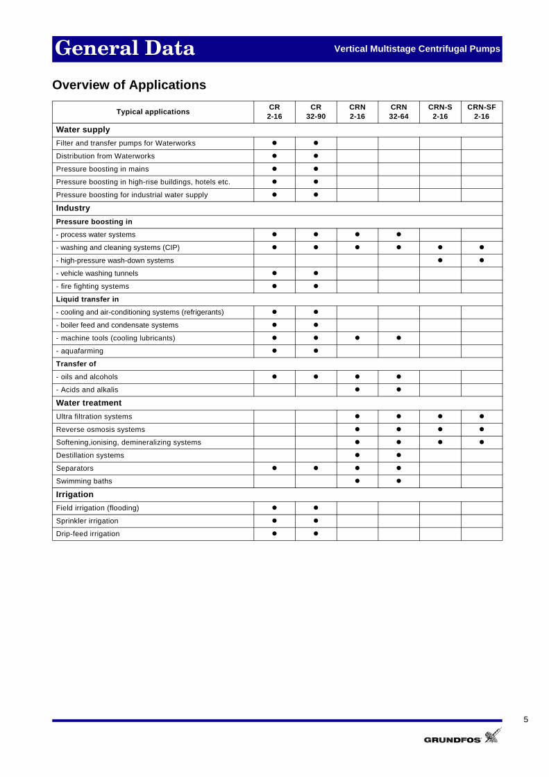
Overview of Applications
Typical applicationsCR
2-16CR
32-90CRN2-16
CRN32-64
CRN-S2-16
CRN-SF2-16
Water supply
Filter and transfer pumps for Waterworks z z
Distribution from Waterworks z z
Pressure boosting in mains z z
Pressure boosting in high-rise buildings, hotels etc. z z
Pressure boosting for industrial water supply z z
Industry
Pressure boosting in
- process water systems z z z z
- washing and cleaning systems (CIP) z z z z z z
- high-pressure wash-down systems z z
- vehicle washing tunnels z z
- fire fighting systems z z
Liquid transfer in
- cooling and air-conditioning systems (refrigerants) z z
- boiler feed and condensate systems z z
- machine tools (cooling lubricants) z z z z
- aquafarming z z
Transfer of
- oils and alcohols z z z z
- Acids and alkalis z z
Water treatment
Ultra filtration systems z z z z
Reverse osmosis systems z z z z
Softening,ionising, demineralizing systems z z z z
Destillation systems z z
Separators z z z z
Swimming baths z z
Irrigation
Field irrigation (flooding) z z
Sprinkler irrigation z z
Drip-feed irrigation z z
6
General Data Vertical Multistage Centrifugal Pumps
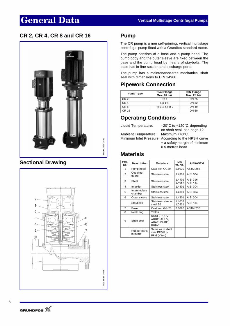
CR 2, CR 4, CR 8 and CR 16
Sectional Drawing
PumpThe CR pump is a non self-priming, vertical multistagecentrifugal pump fitted with a Grundfos standard motor.
The pump consists of a base and a pump head. Thepump body and the outer sleeve are fixed between thebase and the pump head by means of staybolts. Thebase has in-line suction and discharge ports.
The pump has a maintenance-free mechanical shaftseal with dimensions to DIN 24960.
Pipework Connection
Operating ConditionsLiquid Temperature: –20°C to +120°C, depending
on shaft seal, see page 12.Ambient Temperature: Maximum +40°C.Minimum Inlet Pressure: According to the NPSH curve
+ a safety margin of minimum0.5 metres head
MaterialsTM
00 3
685
2496
TM
01 1
834
0498
6
9
2
1
8
3
4
5 7
Pump Type Oval FlangeMax. 16 bar
DIN FlangeMax. 25 bar
CR 2 Rp 1 DN 25
CR 4 Rp 1¼ DN 32 CR 8 Rp 1½ & Rp 2 DN 40 CR 16 DN 50
Pos.no. Description Materials DIN
W.-No. AISI/ASTM
1 Pump head Cast iron GG20 0.6020 ASTM 25B
2 Coupling guard Stainless steel 1.4301 AISI 304
3 Shaft Stainless steel 1.44011.4057
AISI 316AISI 431
4 Impeller Stainless steel 1.4301 AISI 304
5 Intermediatechamber
Stainless steel 1.4301 AISI 304
6 Outer sleeve Stainless steel 1.4301 AISI 304
Staybolts Stainless steel orsteel 50
1.40571.0531 AISI 431
7 Base Cast iron GG 20 0.6020 ASTM 25B
8 Neck ring Teflon
9 Shaft seal
RUUE, RUUV,AUUE, AUUV, AUAE, BUBE,BUBV
Rubber partsin pump
Same as in shaft seal EPDM or FPM (Viton)

7
General Data Vertical Multistage Centrifugal Pumps
CR 32, CR 45, CR 64 and CR 90
Sectional Drawing
PumpThe CR pump is a non self-priming, vertical multistagecentrifugal pump fitted with a Grundfos standard motor.
The pump consists of a base, a motor stool and a pumphead. The chamber stack and the outer sleeve are se-cured between the pump head and the base by meansof staybolts. The base has suction and discharge portson the same level (in-line). The motor stool houses thepump-motor coupling.
The pump is equipped with a maintenance-free mecha-nical shaft seal of the cartridge type.
Pipework Connection
Operating ConditionsLiquid Temperature: –30°C to +150°C, depending
on shaft seal, see page 12.Ambient Temperature: Maximum +40°C.Minimum Inlet Pressure: According to the NPSH curve
+ a safety margin of minimum0.5 metres head.
Materials
� TC= Tungsten Carbide
TM
01 2
150
1298
TM
01 1
836
0498
2
3
4
1
6
8
5
7
10
11
9
12
13
Pump Type FlexibleDIN flange
DIN FlangeOption
CR 32 DN 65 DN 80CR 45 DN 80 DN 100CR 64 DN 100 DN 125
CR 90 DN 100 DN 125
Pos.no. Description Materials DIN
W. -No. AISI/ASTM
1 Pump head Cast ironGGG50 0.7050 ASTM 80-55-06
2 Motor stool Cast ironGG20 0.6020 ASTM 25B
3 Coupling guard Stainless steel 1.4016 AISI 430
4 Shaft Stainless steel 1.4057 AISI 4315 Impeller Stainless steel 1.4301 AISI 304
6Intermediatechamber Stainless steel 1.4301 AISI 304
7 Outer sleeve Stainless steel 1.4301 AISI 304
8 Staybolts Steel ETG 25 AISI 304
9 Base Cast ironGGG50
0.7050 ASTM 80-55-06
10 Neckring Acoflon 21511 Bearing Bronze
12 BottomBearing TC/TC�
13 Shaft seal
EUUE, EUUV, EUHE, EUHV, EUBV, EUBE, HUBE, HUBV
Rubber parts in pump
Same as in shaft seal EPDM or FPM (Viton)
8
General Data Vertical Multistage Centrifugal Pumps
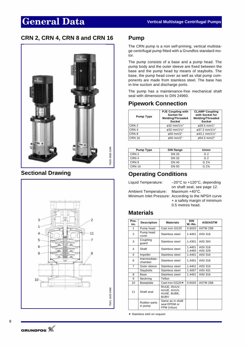
CRN 2, CRN 4, CRN 8 and CRN 16
Sectional Drawing
PumpThe CRN pump is a non self-priming, vertical multista-ge centrifugal pump fitted with a Grundfos standard mo-tor.
The pump consists of a base and a pump head. Thepump body and the outer sleeve are fixed between thebase and the pump head by means of staybolts. Thebase, the pump head cover as well as vital pump com-ponents are made from stainless steel. The base hasin-line suction and discharge ports.
The pump has a maintenance-free mechanical shaftseal with dimensions to DIN 24960.
Pipework Connection
Operating ConditionsLiquid Temperature: –20°C to +120°C, depending
on shaft seal, see page 12.Ambient Temperature: Maximum +40°C.Minimum Inlet Pressure: According to the NPSH curve
+ a safety margin of minimum0.5 metres head.
Materials
� Stainless stell on request
TM
00 3
686
2496
TM
01 1
835
0498
3
1
2
7
4
5
6
89
10
11
Pump Type
PJE Coupling with Socket for
Welding/Threaded Socket
CLAMP Coupling with Socket for
Welding/Threaded Socket
CRN 2 ø32 mm/1¼" ø28.5 mm/1"CRN 4 ø32 mm/1¼" ø37.2 mm/1¼"CRN 8 ø50 mm/2" ø43.1 mm/1½"
CRN 16 ø50 mm/2" ø54.5 mm/2"
Pump Type DIN flange UnionCRN 2 DN 25 G 2CRN 4 DN 32 G 2CRN 8 DN 40 G 2¾
CRN 16 DN 50 G 2¾
Pos.no. Description Materials DIN
W.-No. AISI/ASTM
1 Pump head Cast iron GG20 0.6020 ASTM 25B
2 Pump head cover
Stainless steel 1.4401 AISI 316
3 Coupling guard
Stainless steel 1.4301 AISI 304
4 Shaft Stainless steel 1.44011.4460
AISI 316AISI 329
5 Impeller Stainless steel 1.4401 AISI 316
6Intermediate-chamber Stainless steel 1.4401 AISI 316
7 Outer sleeve Stainless steel 1.4401 AISI 316
Staybolts Stainless steel 1.4057 AISI 4318 Base Stainless steel 1.4401 AISI 3169 Neckring Teflon
10 Baseplate Cast iron GG20� 0.6020 ASTM 25B
11 Shaft seal
RUUE, RUUV,AUUE, AUUV, AUAE, BUBE,BUBV
Rubber partsin pump
Same as in shaft seal EPDM or FPM (Viton)

9
General Data Vertical Multistage Centrifugal Pumps
CRN 32, CRN 45 and CRN 64
Sectional Drawing
PumpThe CRN pump is a non self-priming, vertical multista-ge centrifugal pump fitted with a Grundfos standard mo-tor.
The pump consists of a base, a motor stool and a pumphead. The chamber stack and the outer sleeve are se-cured between the pump head and the base by meansof staybolts. The base, the pump head cover and allcomponents in contact with the pumped liquid are madeof stainless steel. The base has suction and dischargeports on the same level (in-line). The motor stoolhouses the pump-motor coupling.
The pump is equipped with a maintenance-free mecha-nical shaft seal of the cartridge type.
Pipework Connection
Operating ConditionsLiquid Temperature: –30°C to +150°C, depending
on shaft seal, see page 12.Ambient Temperature: Maximum +40°C.Minimum Inlet Pressure: According to the NPSH curve
+ a safety margin of minimum0.5 metres head.
Materials
� TC= Tungsten Carbide�� Stainless stell on request
TM
01 2
149
1298
TM
01 1
837
0498
11
10
13
12
14
2
3
4
1
6
8
5
7
9
Pump Type FlexibleDIN flange
DIN flangeOption
CRN 32 DN 65 DN 80CRN 45 DN 80 DN 100
CRN 64 DN 100 DN 125
Pos.no. Description Materials DIN
W- No. AISI/ASTM
1 Pump head Stainless steel 1.4408 AISI 316 LN
2 Motor stool Cast ironGG20
0.6020 ASTM 25B
3 Coupling guard
Stainless steel 1.4016 AISI 314
4 Shaft Stainless steel 1.44625 Impeller Stainless steel 1.4401 AISI 316
6 Intermediatechamber Stainless steel 1.4401 AISI 316
7 Outer sleeve Stainless steel 1.4401 AISI 3168 Staybolts Stainless steel 1.4057 AISI 4319 Base Stainless steel 1.4401 AISI 316
10 Neckring Acoflon 21511 Bearing HY 49
12BottomBearing TC/TC�
13 BaseplateCast ironGGG50��
0.7050 ASTM 80-55-06
14 Shaft seal
EUUE, EUUV, EUHE, EUHV, EUBV, EUBE, HUBE, HUBV
Rubber partsin pump
Same as in shaft seal EPDM or FPM (Viton)

10
General Data Vertical Multistage Centrifugal Pumps
CRN-S
Sectional Drawing
PumpThe CRN-S pump is a non self-priming, vertical multi-stage centrifugal pump fitted with a Grundfos standardmotor.
The pump consists of a base and a pump head. Thepump body and the outer sleeve are fixed between thebase and the pump head by means of clamping plates.The base, the pump head cover as well as vital pumpcomponents are made from stainless steel. The basehas in-line suction and discharge ports.
The pump has a maintenance-free mechanical shaftseal with dimensions to DIN 24960.
Pipework Connection
Operating ConditionsLiquid Temperature: –20°C to +120°C, depending
on shaft seal, see page 12.Ambient Temperature: Maximum +40°C.Minimum Inlet Pressure: According to the NPSH curve
+ a safety margin of minimum0.5 metres head.
Materials
� Stainless steel on request
TM
00 3
687
2496
TM
00 3
167
0798
5
6
7
3
1
9
8
4
2
12
10
11
Pump Type PJE Coupling with Socket for Welding/
Threaded Socket DIN Flange
CRN 2-S ø32 mm/1¼" DN 25
CRN 4-S ø32 mm/1¼" DN 32
CRN 8-S ø50 mm/2" DN 40
CRN 16-S ø50 mm/2" DN 50
Pos.no. Description Materials DIN
W- No. AISI/ASTM
1 Pump head Cast iron GG20 0.6020 ASTM 25B
2 Pump head cover
Stainless steel 1.4401 AISI 316
3 Coupling guard
Stainless steel 1.4301 AISI 304
4 Shaft Stainless steel 1.44011.4460
AISI 316AISI 329
5 Impeller Stainless steel 1.4401 AISI 316
6Intermediate-chamber Stainless steel 1.4401 AISI 316
7 Outer sleeve Stainless steel 1.4401 AISI 316
8 Clamping plate
Cast iron 37-2 1.0037
9 Base Stainless steel 1.4401 AISI 316
10 Neckring Teflon
11 Baseplate Cast iron GG20� 0.6020 ASTM 25B
12 Shaft seal
RUUE, RUUV,AUUE, AUUV, AUAE, BUBE,BUBV
Rubber partsin pump
Same as in shaft seal EPDM or FPM (Viton)

11
General Data Vertical Multistage Centrifugal Pumps
CRN-SF
Sectional Drawing
PumpThe CRN-SF pump is a non self-priming, vertical multi-stage centrifugal pump fitted with a Grundfos standardmotor.
The pump consists of a base and a pump head. Thepump body and the outer sleeve are fixed between thebase and the pump head by means of clamping plates.
The direction of rotation is opposite to that of the otherpumps, and the pump body is upside-down, thus givingthe opposite direction of flow of liquid.
The base, the pump head cover as well as vital pumpcomponents are made from stainless steel. The basehas in-line suction and discharge ports.
The pump has a maintenance-free mechanical shaftseal with dimensions to DIN 24960.
Pipework Connection
Operating ConditionsLiquid Temperature: –15°C to +90°C, depending
on shaft seal, see page 12.Ambient Temperature: Maximum +40°C.Minimum Inlet Pressure: 2 bar during operation.
Materials
TM
00 3
688
2496
TM
00 3
170
0798
5
6
7
3
1
9
8
4
2
10
11
12
Pump Type
PJE Coupling
with Threaded Socket
with Socket for Welding
CRN 2-SF 1¼" ø32 mm
CRN 4-SF 1¼" ø32 mm
CRN 8-SF 2" ø50 mm
CRN 16-SF 2" ø50 mm
Pos.no. Description Materials DIN
W.- No. AISI/ASTM
1 Pump head Cast iron GG20 0.6020 ASTM 25B
2 Pump head cover Stainless steel 1.4401 AISI 316
3 Coupling guard Stainless steel 1.4301 AISI 304
4 Shaft Stainless steel 1.44011.4460
AISI 316AISI 329
5 Impeller Stainless steel 1.4401 AISI 316
6 Intermediate-chamber
Stainless steel 1.4401 AISI 316
7 Outer sleeve Stainless steel 1.4401 AISI 316
8Clamping plate Steel 37-2 1.0037
9 Base Stainless steel 1.4401 AISI 316
10 Neckring Acoflon 215
11 Baseplate Cast iron GG20� 0.6020 ASTM 25B
12 Shaft seal
RUUE, RUUV,AUUE, AUUV, AUAE, BUBE,BUBV
Rubber parts in pump
Same as in shaft seal EPDM or FPM (Viton)
12
General Data Vertical Multistage Centrifugal Pumps
Pumped LiquidsThin, non-explosive liquids, not containing solid parti-cles or fibres. The liquid must not attack the pump ma-terials chemically.
When pumping liquids with a density and/or viscosityhigher than that of water, motors with correspondinglyhigher outputs must be used, if required.
Whether a pump is suitable for a particular liquid de-pends on a number of factors of which the most impor-tant are chloride content, pH value, temperature andcontent of solvents, oils etc.
Please note that aggressive liquids (e.g. sea water)may destroy the oxide film which protects the stainlesssteel and thus cause corrosion.
CR, CRNFor liquid transfer, circulation and pressure boosting ofcold or hot clean water.
CRN In systems where all parts in contact with the liquidmust be made of stainless steel, CRN pumps must beused.
MotorThe motor is a totally enclosed, fan-cooled, 2-poleGrundfos standard motor with principal dimensions inaccordance with the IEC and DIN standards.
Electrical tolerances according to IEC 34/EN 60034.
Mounting:– up to 4 kW: V 18,– from 5.5 kW: V 1
Insulation Class: F.Enclosure Class: IP 55, On request: IP 44 and IP 54.50 Hz Standard-Voltages: 3 x 200/346 V,
3 x 200-220/346-380V,3 x 220-240/380-415V,3 x 380-415∆ V,1 x 220-230/240 V,1 x 110/220 V.
Motors for other voltages are available on request.
Single-phase motors have a built-in thermal overloadswitch.
Three-phase motors must be connected to a motorstarter in accordance with local regulations.
Three-phase Grundfos motors from 3 kW upwards havea built-in thermistor (PTC) according to DIN 44082.
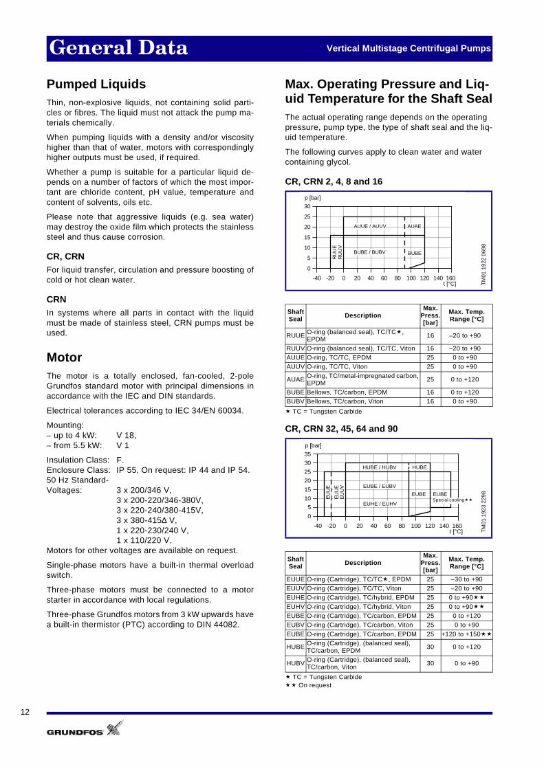
Max. Operating Pressure and Liq-uid Temperature for the Shaft SealThe actual operating range depends on the operating pressure, pump type, the type of shaft seal and the liq-uid temperature.
The following curves apply to clean water and water containing glycol.
CR, CRN 2, 4, 8 and 16
� TC = Tungsten Carbide
CR, CRN 32, 45, 64 and 90
� TC = Tungsten Carbide�� On request
TM
01 1
922
0698
Shaft Seal Description
Max. Press.[bar]
Max. Temp. Range [°C]
RUUE O-ring (balanced seal), TC/TC�, EPDM 16 –20 to +90
RUUV O-ring (balanced seal), TC/TC, Viton 16 –20 to +90AUUE O-ring, TC/TC, EPDM 25 0 to +90AUUV O-ring, TC/TC, Viton 25 0 to +90
AUAE O-ring, TC/metal-impregnated carbon, EPDM 25 0 to +120
BUBE Bellows, TC/carbon, EPDM 16 0 to +120BUBV Bellows, TC/carbon, Viton 16 0 to +90
TM
01 1
923
2298
Shaft Seal Description
Max. Press.[bar]
Max. Temp. Range [°C]
EUUE O-ring (Cartridge), TC/TC�, EPDM 25 –30 to +90EUUV O-ring (Cartridge), TC/TC, Viton 25 –20 to +90EUHE O-ring (Cartridge), TC/hybrid, EPDM 25 0 to +90��
EUHV O-ring (Cartridge), TC/hybrid, Viton 25 0 to +90��
EUBE O-ring (Cartridge), TC/carbon, EPDM 25 0 to +120EUBV O-ring (Cartridge), TC/carbon, Viton 25 0 to +90
EUBE O-ring (Cartridge), TC/carbon, EPDM 25 +120 to +150��
HUBE O-ring (Cartridge), (balanced seal),TC/carbon, EPDM
30 0 to +120
HUBV O-ring (Cartridge), (balanced seal),TC/carbon, Viton
30 0 to +90
-40 -20 0 20 40 60 80 100 120 140 160
0
5
10
15
20
25
30
p [bar]
AUUE / AUUV AUAE
BUBEBUBE / BUBV
RU
UE
RU
UV
t [°C]
-40 -20 0 20 40 60 80 100 120 140 160
0
5
10
15
20
25
30
35
p [bar]
EUHE / EUHV
EUBE
HUBE / HUBV HUBE
EU
UE
EU
UE
EU
UV
EUBE
EUBE / EUBV
t [°C]
Special cooling��
13
General Data Vertical Multistage Centrifugal Pumps
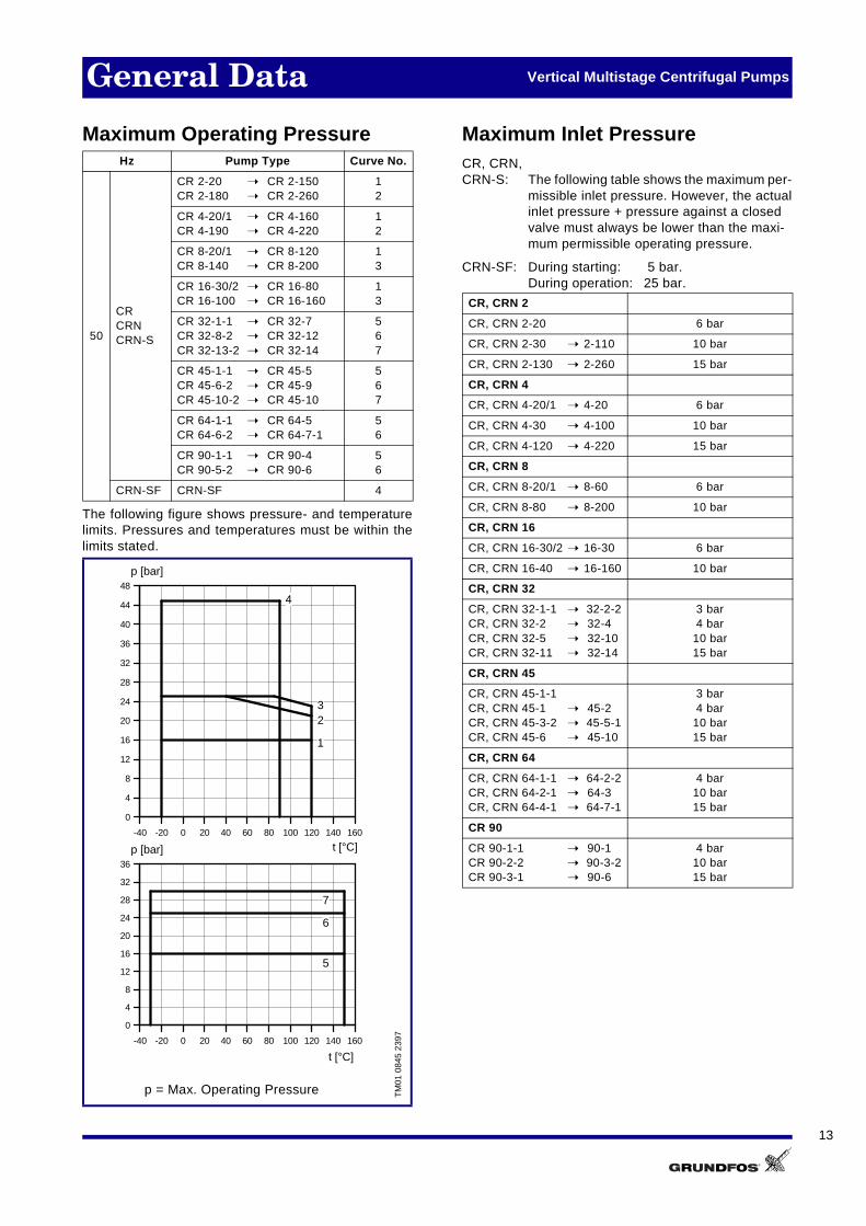
Maximum Operating Pressure
The following figure shows pressure- and temperaturelimits. Pressures and temperatures must be within thelimits stated.
Maximum Inlet PressureCR, CRN, CRN-S: The following table shows the maximum per-
missible inlet pressure. However, the actualinlet pressure + pressure against a closedvalve must always be lower than the maxi-mum permissible operating pressure.
CRN-SF: During starting: 5 bar.During operation: 25 bar.
Hz Pump Type Curve No.
50
CRCRNCRN-S
CR 2-20 ➝ CR 2-150CR 2-180 ➝ CR 2-260
12
CR 4-20/1 ➝ CR 4-160CR 4-190 ➝ CR 4-220
12
CR 8-20/1 ➝ CR 8-120CR 8-140 ➝ CR 8-200
13
CR 16-30/2 ➝ CR 16-80CR 16-100 ➝ CR 16-160
13
CR 32-1-1 ➝ CR 32-7CR 32-8-2 ➝ CR 32-12CR 32-13-2 ➝ CR 32-14
567
CR 45-1-1 ➝ CR 45-5CR 45-6-2 ➝ CR 45-9CR 45-10-2 ➝ CR 45-10
567
CR 64-1-1 ➝ CR 64-5CR 64-6-2 ➝ CR 64-7-1
56
CR 90-1-1 ➝ CR 90-4CR 90-5-2 ➝ CR 90-6
56
CRN-SF CRN-SF 4
TM
01 0
845
2397
p = Max. Operating Pressure
-40 -20 0 20 40 60 80 100 120 140 160
t [°C]
0
4
8
12
16
20
24
28
32
36
40
44
48
p [bar]
1
23
4
-40 -20 0 20 40 60 80 100 120 140 160
t [°C]
0
4
8
12
16
20
24
28
32
36
p [bar]
5
6
7
CR, CRN 2
CR, CRN 2-20 6 bar
CR, CRN 2-30 ➝ 2-110 10 bar
CR, CRN 2-130 ➝ 2-260 15 bar
CR, CRN 4
CR, CRN 4-20/1 ➝ 4-20 6 bar
CR, CRN 4-30 ➝ 4-100 10 bar
CR, CRN 4-120 ➝ 4-220 15 bar
CR, CRN 8
CR, CRN 8-20/1 ➝ 8-60 6 bar
CR, CRN 8-80 ➝ 8-200 10 bar
CR, CRN 16
CR, CRN 16-30/2 ➝ 16-30 6 bar
CR, CRN 16-40 ➝ 16-160 10 bar
CR, CRN 32
CR, CRN 32-1-1 ➝ 32-2-2CR, CRN 32-2 ➝ 32-4CR, CRN 32-5 ➝ 32-10CR, CRN 32-11 ➝ 32-14
3 bar4 bar
10 bar15 bar
CR, CRN 45
CR, CRN 45-1-1 CR, CRN 45-1 ➝ 45-2CR, CRN 45-3-2 ➝ 45-5-1CR, CRN 45-6 ➝ 45-10
3 bar4 bar
10 bar15 bar
CR, CRN 64
CR, CRN 64-1-1 ➝ 64-2-2CR, CRN 64-2-1 ➝ 64-3CR, CRN 64-4-1 ➝ 64-7-1
4 bar10 bar15 bar
CR 90
CR 90-1-1 ➝ 90-1CR 90-2-2 ➝ 90-3-2CR 90-3-1 ➝ 90-6
4 bar10 bar15 bar

14
General Data Vertical Multistage Centrifugal Pumps
Type Key
CR, CRN 2, 4, 8 and 16
CR, CRN 32, 45, 64 and CR 90
Codes
Example CR N 16- 30 /2 A - FJ - G - AUUE
Pump Range
Version with vital parts in stainless steel.DIN W.-No. 1.4401(AISI 316)
Nominal flow rate [m3/h]
Number of stages x 10
Number of impellers(Only used if the pump has fewerimpellers than chambers)
Code for pump version
Code for pipework connection
Code for materials, excl. plastic and rubber parts
Code for shaft seal and plastic/rubber parts, excluding neck ring
Example CR 32 - 2 - 1 - X - X - X - X - XXXX
Pump Range: CR, CRN
Nominal flow rate [m3/h]
Number of stages
Number of reduced impellers
Code for pump version
Code for pipework connection
Code for materials
Code for rubber parts in the pump
Code for shaft seal
Example A - F - A - X - B U B EPump Version
A Basic version
SF High pressure pumpwithout staybolts
S Pump without staybolts
H Horizontal version. Base with horizontal suc-tion port and vertical dis-charge port
R Horizontal version withbearing bracket
B Oversize motor,1 flange size bigger
P Undersize motor,1 flange size smaller
T Oversize motor,2 flanges sizes bigger
Pipework Connection
A Oval flange
C CLAMP coupling
F DIN flange
N Changed diameter of ports
P PJE coupling
O External thread, Union
Materials
A Basic version
G Stainless steel parts in 1.4401 or similar class
J Shaft and/or outer sleeve in 1.4401 or similar class
K Bronze intermediatechamber bearing
Code for rubber parts in pump(Only CR, CRN 32, 45, 64 and CR 90)
E EPDM
V FPM (Viton)
Shaft Seal B U B E
A O-ring seal with fixed driver
H Balanced seal, cartridge
B Rubber bellows seal
D Balanced seal
E Cartridge with O-ring(only CR, CRN 32, 4564 and CR 90)
A Carbon, syntheticmetal-impregnated
B Carbon, syntheticresin-impregnated
U Tungsten carbide(wolfram carbide)
Q Silicon carbide
H Wolfram carbide
E EPDM
V FPM (Viton)
K PFE (Kalrez)

15
General Data Vertical Multistage Centrifugal Pumps
Performance CurvesThe guidelines below apply to the curves shown on thefollowing pages:
1. Tolerances to ISO 2548, Annex B, if indicated.
2. The motors used for the measurements are stan-dard Grundfos motors.
3. Measurements were made with airless water at atemperature of 20°C.
4. The curves apply to a kinematic viscosity of υ = 1 mm2/s (1 cSt).
5. Due to the risk of overheating, the pumps shouldnot be used at a flow below the minimum flow rate.
The curve below shows the minimum flow rate as apercentage of the nominal flow rate in relation tothe liquid temperature.
TM
01 3
122
3498
0 4 8 12 16 20 24 28 32 36 Q [m³/h]
0
5
10
15
20
25
30
40
45
50
55
60
H[m]
0 2 4 6 8 10 Q [l/s]
0.0
0.1
0.2
0.3
0.4
0.5
0.6[MPa]
p
CR 3250 Hz
ISO 2548 Annex B
-2
-2-2
0 4 8 12 16 20 24 28 32 36 Q [m³/h]
0.0
1.0
P2[kW]
020406080100
[%]Eta
0.0
1.0
[hp]P2
eta
1/12/3
0 4 8 12 16 20 24 28 32 36 Q [m³/h]
01020
[m]H
0246
NPSH[m]
0100200
[kPa]p
NPSH1/1
2/3
Pump type and frequency
QH-curve for the individual pump.The bold curves indicate the re-commended performance range. Thethin curves are only a guide .
The NPSH-curve is an averagecurve for all the variants shown. When dimensioning the pumps,add a safety margin of at least0.5 m.
QH-curve per stage. Curves for complete (1/1) and reduced-diameter (2/3) impellers are shown.
The power curves indicatepump input power per sta-ge. Curves are shown forcomplete (1/1) and for re-duced-diameter (2/3) im-pellers.
Number of stages.First figure: number of sta-ges; second figure: number ofreduced-diameter impel-lers
The eta-curve shows pump efficiency. The efficiency for pumps with re-duced-diameter impellers is ap-prox. 2% lower than the eta-curve shown in the chart.
TM
01 2
816
2498
40 60 80 100 120 140 t [°C]
0
10
20
30
Qmin[%]

16
Dimensioning Vertical Multistage Centrifugal Pumps
Selection of CR, CRN PumpPump SizeSelection of pump size should be based on:
• consumption pattern,
• highest possible flow and pressure (peak values),
• economy.
As a rule of thumb pipes should be dimensioned in sucha way that the velocity of the liquid does not exceed 1to 1.5 m/sec.
EfficiencyIf the pump is always to operate in the same duty point,select a pump where this duty point coincides with thehighest efficiency.
In case of controlled operation or varying consumption,select a pump whose highest efficiency falls within theduty range representing the highest power consumpti-on, i.e. typically the duty range covering the greater partof the duty time.
NPSHIf the pressure in the pump is lower than the vapourpressure of the pumped liquid this may cause cavitati-on. To avoid cavitation, make sure that there is a mini-mum pressure on the suction side of the pump. Themaximum suction lift “H” in metres head can be calcu-lated as follows:
H = pb x 10.2 – NPSH – Hf – Hv – Hs
pb = Barometric pressure in bar. (Barometric pressure can be set to 1 bar). In closed systems, pb indicates the system pressure in bar.
NPSH = Net Positive Suction Head in metres head (to be read from the NPSH curve on at thehighest flow the pump will be delivering).
Hf = Friction loss in suction pipe in metres head(at the highest flow the pump will be deliver-ing.)
Hv = Vapour pressure in metres head.
Hs = Safety margin = minimum 0.5 metres head.
If the calculated “H” is positive, the pump can operateat a suction lift of maximum “H” metres head.
If the calculated “H” is negative, an inlet pressure of mi-nimum “H” metres head is required.
The pump must be able to fulfil the flow andpressure requirements.
Check that the highest efficiency falls withinthe marked duty range.
Check that the pump does not have and willnot be exposed to cavitation.
TM
01 2
021
3498
TM
01 2
022
3498
TM
01 1
242
4097
- T
M00
303
7 34
93
0 20 40 60 80 100
0
5
10
15
20
25
30H [m]
Q [m³/h]
0 20 40 60 80 100
0
20
40
60
80
Eta[%] +
÷
÷
Q [m³/h]
Hv
H NPSHPb
Hf
20
15
1210
8,0
6,05,0
4,0
3,0
2,0
1,00,8
0,6
0,40,3
0,2
0,1
1,5
120
110
90
100
80
70
60
50
40
30
20
10
0
Hv(m)
tm(°C)
150
130
140
25
35
4540
30

17
Dimensioning Vertical Multistage Centrifugal Pumps
MaterialThe material variant (CR/CRN) is to be selected on thebasis of the liquid to be pumped. The product rangecovers two basic types.
• CR is suitable for clean, non-aggressive liquids such as potable water, oils, etc.
• CRN is suitable for clean, slightly aggressive liquids such as salt water, acids, etc. (see list of pumped liquids page 64).
Shaft SealThe shaft seal is to be selected on the basis of liquidtemperature and max. pressure.
For other liquids than water, the chemical resistance ofthe materials - incl. seal face, seat and rubber compo-nents of the shaft seal - must be taken into account.
Parallel OperationIt may be an advantage to install a number of pumpsconnected in parallel instead of one big pump. Amongthe advantages are for instance:
• adaptation to the required duty point in systems with varying flow profile,
• increased reliability of supply as only part of the system capacity is affected in case of pump failure.
MiscellaneousIn case of liquid viscosity and relative density differentfrom that of water, motor size and pump performancemust be taken into account.
The material variant must be suitable for thepumped liquid (CR or CRN).
The shaft seal material and variant must besuitable for the pumped liquid.
In case the duty profile varies, consider theinstallation of two or more pumps in parallel.
TM
01 2
100
1198
TM
01 2
024
3498
TM
01 2
023
3498
0
5
10
15
20
25
30
35
90-30 1500
p [bar]
t [°C]
0 20 40 60 80
0
5
10
15
20
25
30
100
H [m]
Q [m³/h]

18
Performance Curves CR 2
TM
00 0
409
3498
0.0 0.2 0.4 0.6 0.8 1.0 1.2 1.4 1.6 1.8 2.0 2.2 2.4 2.6 2.8 3.0 3.2 3.4 Q [m³/h]
0
10
20
30
40
50
60
70
80
90
100
110
120
130
140
150
160
170
180
190
200
210
220
230
240
250
H[m]
0.0 0.1 0.2 0.3 0.4 0.5 0.6 0.7 0.8 0.9 Q [l/s]
0.0
0.1
0.2
0.3
0.4
0.5
0.6
0.7
0.8
0.9
1.0
1.1
1.2
1.3
1.4
1.5
1.6
1.7
1.8
1.9
2.0
2.1
2.2
2.3
2.4
[MPa]p
CR 250 Hz
ISO 2548 Annex B
-110
-130
-150
-180
-20
-220
-260
-30-40-50
-60-70
-90
0.0 0.2 0.4 0.6 0.8 1.0 1.2 1.4 1.6 1.8 2.0 2.2 2.4 2.6 2.8 3.0 3.2 3.4 Q [m³/h]
0.00
0.04
0.08
0.12
0.16
0.20
P2[kW]
0
10
20
30
40
50
[%]Eta
0.00
0.05
0.10
0.15
0.20
0.25
[hp]P2
Eta
P2
0.0 0.2 0.4 0.6 0.8 1.0 1.2 1.4 1.6 1.8 2.0 2.2 2.4 2.6 2.8 3.0 3.2 3.4 Q [m³/h]0
4
8
12[m]H
0
2
4
6
NPSH[m]
0
40
80
120[kPa]
p
QH 2900 rpm
NPSH

19
Technical Data CR 2
Dimensional Sketches Dimensions and Weights
* CR 2 with oval flanges** CR 2 with DIN flanges
Pipework connection:
DIN 2566 with threaded socketDIN 2634 with socket for welding
Electrical Data 3 x 380-415 V, 50 Hz
TM
00 3
091
3397
B2
D2
50
PN25/DN25
ø25
210
Rp 3/8
4 x ø14ø
120
ø85
ø70
4 x ø13180
20
75
22
Rp 1
210
Rp 3/8M10x40
G 1/2
Rp 1/4
4 x ø1375
180
20
147
160
100
B1
250
147
100
G 1/2
G 1/2
D1
Oval
DIN
Pump Type
Dimensions [mm]Net
Weight[kg]
*B1 B2
*B1 + B2
**B1
**B1 + B2 D1 D2 * **
CR 2-20 220 190 410 245 435 140 110 20 25
CR 2-30 240 190 430 265 455 140 110 20 25
CR 2-40 260 190 450 285 475 140 110 20 25
CR 2-50 275 190 465 300 490 140 110 20 25
CR 2-60 300 230 530 325 555 140 110 20 25
CR 2-70 315 230 545 340 570 140 110 25 30
CR 2-90 350 230 580 375 605 140 110 30 35
CR 2-110 385 230 615 410 640 140 110 30 35
CR 2-130 440 280 720 465 745 180 110 30 35
CR 2-150 475 280 755 500 780 180 110 30 35
CR 2-180 280 555 835 180 110 50
CR 2-220 280 625 905 180 110 55
CR 2-260 335 705 1040 180 110 60
Pump TypeMotor Full Load Current
I1/1 [A]Power Factor
Cos ϕ1/1
Motor Efficiencyη[%][kW] [hp]
CR 2-20 0.37 0.50 0.96 0.84-0.76 72 4.8-5.2
CR 2-30 0.37 0.50 0.96 0.84-0.76 72 4.8-5.2
CR 2-40 0.55 0.75 1.44 0.84-0.76 72 4.8-5.2
CR 2-50 0.55 0.75 1.44 0.84-0.76 72 4.8-5.2
CR 2-60 0.75 1.0 1.86 0.86-0.78 74 5.0-5.5
CR 2-70 0.75 1.0 1.86 0.86-0.78 74 5.0-5.5
CR 2-90 1.1 1.5 2.65 0.87-0.79 76 5.2-5.7
CR 2-110 1.1 1.5 2.65 0.87-0.79 76 5.2-5.7
CR 2-130 1.5 2.0 3.40 0.85-0.79 82 6.3-6.9
CR 2-150 1.5 2.0 3.40 0.85-0.79 82 6.3-6.9
CR 2-180 2.2 3.0 4.75 0.87-0.82 84 7.0-7.6
CR 2-220 2.2 3.0 4.75 0.87-0.82 84 7.0-7.6
CR 2-260 3.0 4.0 6.25 0.88-0.82 86 7.8-8.5
Istart
I1 1⁄------------

20
Performance Curves CRN 2
TM
00 0
410
3498
0.0 0.2 0.4 0.6 0.8 1.0 1.2 1.4 1.6 1.8 2.0 2.2 2.4 2.6 2.8 3.0 3.2 3.4 Q [m³/h]
0
10
20
30
40
50
60
70
80
90
100
110
120
130
140
150
160
170
180
190
200
210
220
230
240
250
H[m]
0.0 0.1 0.2 0.3 0.4 0.5 0.6 0.7 0.8 0.9 Q [l/s]
0.0
0.1
0.2
0.3
0.4
0.5
0.6
0.7
0.8
0.9
1.0
1.1
1.2
1.3
1.4
1.5
1.6
1.7
1.8
1.9
2.0
2.1
2.2
2.3
2.4
[MPa]p
CRN 250 Hz
ISO 2548 Annex B
-110
-130
-150
-180
-20
-220
-260
-30-40-50
-60-70
-90
0.0 0.2 0.4 0.6 0.8 1.0 1.2 1.4 1.6 1.8 2.0 2.2 2.4 2.6 2.8 3.0 3.2 3.4 Q [m³/h]
0.00
0.04
0.08
0.12
0.16
0.20
P2[kW]
0
10
20
30
40
50
[%]Eta
0.00
0.05
0.10
0.15
0.20
0.25
[hp]P2
Eta
P2
0.0 0.2 0.4 0.6 0.8 1.0 1.2 1.4 1.6 1.8 2.0 2.2 2.4 2.6 2.8 3.0 3.2 3.4 Q [m³/h]0
4
8
12[m]H
0
2
4
6
NPSH[m]
0
40
80
120[kPa]
p
QH 2900 rpm
NPSH

21
Technical Data CRN 2
Dimensional Sketches Dimensions and Weight
* CRN 2 with PJE or CLAMP couplings or for unions** CRN 2 with DIN flanges
Pipework connection:
DIN 2566 with threaded socketDIN 2634 with socket for welding
Electrical Data 3 x 380-415 V, 50 Hz
TM
00 2
944
1296
G 1/2
G 1/2
100150210
50
42,4
B1
20
210180
4 x ø13
250 ø324 x ø14
ø65
ø85
ø12
5
32
160 ø32
20
PN25-DN25
ø59
75
50
210
50
20
G 2
D1
B2
D2
PJE
CLAMP
UNION
DIN
Pump Type
Dimensions [mm] NetWeight
[kg]*
B1 B2*
B1 + B2**B1
**B1 + B2 D1 D2
CRN 2-20 220 190 410 245 435 140 110 20
CRN 2-30 240 190 430 265 455 140 110 20
CRN 2-40 260 190 450 285 475 140 110 20
CRN 2-50 275 190 465 300 490 140 110 20
CRN 2-60 300 230 530 325 555 140 110 25
CRN 2-70 315 230 545 340 570 140 110 25
CRN 2-90 350 230 580 375 605 140 110 30
CRN 2-110 385 230 615 410 640 140 110 30
CRN 2-130 440 280 720 465 745 180 110 35
CRN 2-150 475 280 755 500 780 180 110 35
CRN 2-180 530 280 810 555 835 180 110 40
CRN 2-220 600 280 880 625 905 180 110 45
CRN 2-260 680 335 1015 705 1040 180 110 50
Pump TypeMotor Full Load Current
I1/1 [A]Power Factor
Cos ϕ1/1
Motor Eficiencyη[%][kW] [hp]
CRN 2-20 0.37 0.50 0.96 0.84-0.76 72 4.8-5.2
CRN 2-30 0.37 0.50 0.96 0.84-0.76 72 4.8-5.2
CRN 2-40 0.55 0.75 1.44 0.84-0.76 72 4.8-5.2
CRN 2-50 0.55 0.75 1.44 0.84-0.76 72 4.8-5.2
CRN 2-60 0.75 1.0 1.86 0.86-0.78 74 5.0-5.5
CRN 2-70 0.75 1.0 1.86 0.86-0.78 74 5.0-5.5
CRN 2-90 1.1 1.5 2.65 0.87-0.79 76 5.2-5.7
CRN 2-110 1.1 1.5 2.65 0.87-0.79 76 5.2-5.7
CRN 2-130 1.5 2.0 3.40 0.85-0.79 82 6.3-6.9
CRN 2-150 1.5 2.0 3.40 0.85-0.79 82 6.3-6.9
CRN 2-180 2.2 3.0 4.75 0.87-0.82 84 7.0-7.6
CRN 2-220 2.2 3.0 4.75 0.87-0.82 84 7.0-7.6
CRN 2-260 3.0 4.0 6.25 0.88-0.82 86 7.8-8.5
Istart
I1 1⁄------------

22
Performance Curves CRN 2-S
TM
00 3
156
3498
0.0 0.2 0.4 0.6 0.8 1.0 1.2 1.4 1.6 1.8 2.0 2.2 2.4 2.6 2.8 3.0 3.2 3.4 Q [m³/h]
0
10
20
30
40
50
60
70
80
90
100
110
120
130
140
150
160
170
180
190
200
210
220
230
240
H[m]
0.0 0.1 0.2 0.3 0.4 0.5 0.6 0.7 0.8 0.9 Q [l/s]
0.0
0.2
0.4
0.6
0.8
1.0
1.2
1.4
1.6
1.8
2.0
2.2
[MPa]p
CRN 2 S 50 Hz
ISO 2548 Annex B
-110 S
-130 S
-150 S
-180 S
-220 S
-260 S
0.0 0.2 0.4 0.6 0.8 1.0 1.2 1.4 1.6 1.8 2.0 2.2 2.4 2.6 2.8 3.0 3.2 3.4 Q [m³/h]
0.00
0.04
0.08
0.12
0.16
P2[kW]
0
10
20
30
40
50[%]Eta
0.0
0.1
0.2
[hp]P2
eta
P2
0.0 0.2 0.4 0.6 0.8 1.0 1.2 1.4 1.6 1.8 2.0 2.2 2.4 2.6 2.8 3.0 3.2 3.4 Q [m³/h]
0
4
8
12
[m]H
0
2
4
NPSH[m]
0
40
80
120[kPa]
p
QH 2900 rpm
NPSH

23
Technical Data CRN 2-S
Dimensional Sketches Dimensions and Weights
* CRN 2 S with PJE couplings** CRN 2 S with DIN flanges
Pipework connection:
DIN 2566 with threaded socketDIN 2634 with socket for welding
Electrical Data 3 x 380-415 V, 50 Hz
TM
00 2
945
1296
G 1/2
100150210
50
42,
4
20
210
180
4 x ø13
250 ø32 4 x ø14
ø12
5
32
PN25-DN25
75
G 1/2
D1
B2
D2
B1
ø65
ø85
PJE
DIN
Pump Type
Dimensions [mm] NetWeight
[kg]*
B1 B2*
B1 + B2**B1
**B1 + B2 D1 D2
CRN 2-110 S 385 230 615 410 640 140 110 35
CRN 2-130 S 440 280 720 465 745 180 110 40
CRN 2-150 S 475 280 755 500 780 180 110 40
CRN 2-180 S 530 280 810 555 835 180 110 45
CRN 2-220 S 600 280 880 625 905 180 110 50
CRN 2-260 S 680 335 1015 705 1040 180 110 55
Pump TypeMotor Full Load Current
I1/1 [A]Power Factor
Cos ϕ1/1
Motor Efficiencyη[%][kW] [hp]
CRN 2-110 S 1.1 1.5 2.65 0.87-0.79 76 5.2-5.7
CRN 2-130 S 1.5 2.0 3.40 0.85-0.79 82 6.3-6.9
CRN 2-150 S 1.5 2.0 3.40 0.85-0.79 82 6.3-6.9
CRN 2-180 S 2.2 3.0 4.75 0.87-0.82 84 7.0-7.6
CRN 2-220 S 2.2 3.0 4.75 0.87-0.82 84 7.0-7.6
CRN 2-260 S 3.0 4.0 6.25 0.88-0.82 86 7.8-8.5
Istart
I1 1⁄------------

24
Performance Curves CRN 2-SF
TM
00 3
689
4098
0.0 0.4 0.8 1.2 1.6 2.0 2.4 2.8 3.2Q [m³/h]
100
120
140
160
180
200
220
240
260
280
300
320
340
360
380
400
420
440
460
H[m]
0.0 0.2 0.4 0.6 0.8 Q [l/s]
1.2
1.6
2.0
2.4
2.8
3.2
3.6
4.0
4.4
[MPa]p
CRN 2-260/24 SF +CRN 2-
50 Hz
CRN 2-260/24 SF
+CRN2-30
+CRN2-40
+CRN2-50
+CRN2-60
+CRN2-70
+CRN2-90
+CRN2-110
+CRN2-130
+CRN2-150
+CRN2-180
+CRN2-220
+CRN2-260 *
*
0.0 0.4 0.8 1.2 1.6 2.0 2.4 2.8 3.2Q [m³/h]
0.00
0.04
0.08
0.12
0.16
P2[kW]
0.0
0.1
0.2
[hp]P2
0
10
20
30
40
50
[%]Eta
P2
eta
25
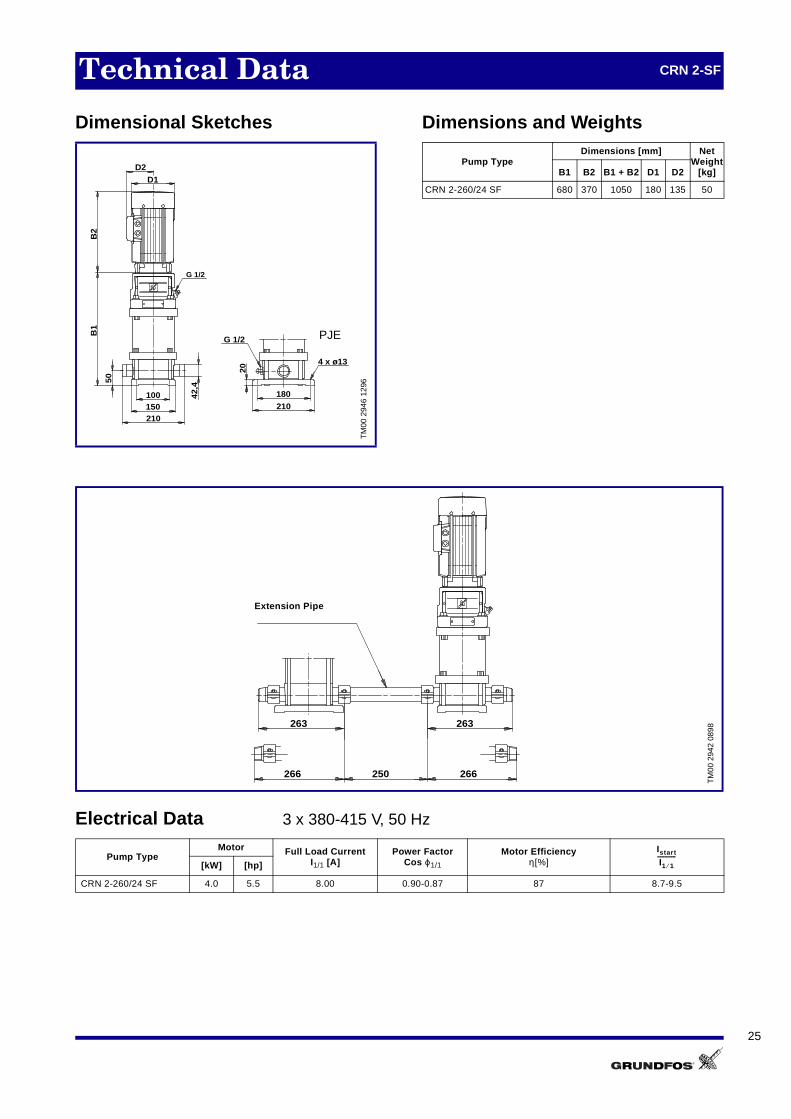
Technical Data CRN 2-SF
Dimensional Sketches Dimensions and Weights
Electrical Data 3 x 380-415 V, 50 Hz
TM
00 2
946
1296
G 1/2
20
210
180
4 x ø13
100150210
50
42,
4
G 1/2
D1
B2
D2
B1
PJE
Pump TypeDimensions [mm] Net
Weight[kg]B1 B2 B1 + B2 D1 D2
CRN 2-260/24 SF 680 370 1050 180 135 50
TM
00 2
942
0898
Pump TypeMotor Full Load Current
I1/1 [A]Power Factor
Cos ϕ1/1
Motor Efficiencyη[%][kW] [hp]
CRN 2-260/24 SF 4.0 5.5 8.00 0.90-0.87 87 8.7-9.5
263 263
266 266250
Extension Pipe
Istart
I1 1⁄------------

26
Performance Curves CR 4
TM
00 0
411
3498
0.0 0.5 1.0 1.5 2.0 2.5 3.0 3.5 4.0 4.5 5.0 5.5 6.0 6.5 7.0 7.5 Q [m³/h]
0
10
20
30
40
50
60
70
80
90
100
110
120
130
140
150
160
170
180
190
200
210
220
H[m]
0.0 0.2 0.4 0.6 0.8 1.0 1.2 1.4 1.6 1.8 2.0 Q [l/s]
0.0
0.2
0.4
0.6
0.8
1.0
1.2
1.4
1.6
1.8
2.0
2.2[MPa]
p
CR 4 50 Hz
ISO 2548 Annex B
-20
-20/1
-30
-40
-50
-60
-80
-80/7
-100
-120
-160/14
-160
-190
-220
0.0 0.5 1.0 1.5 2.0 2.5 3.0 3.5 4.0 4.5 5.0 5.5 6.0 6.5 7.0 7.5 Q [m³/h]
0.00
0.04
0.08
0.12
0.16
0.20
P2[kW]
0
10
20
30
40
50
60[%]Eta
0.0
0.1
0.2
[hp]P2
eta
P2
0.0 0.5 1.0 1.5 2.0 2.5 3.0 3.5 4.0 4.5 5.0 5.5 6.0 6.5 7.0 7.5 Q [m³/h]
0
2
4
6
8
[m]H
0.0
0.4
0.8
1.2
1.6
NPSH[m]
0
40
80
[kPa]p
QH 2900 rpm
NPSH

27
Technical Data CR 4
Dimensional Sketches Dimensions and Weights
* CR 4 with oval flanges** CR 4 with DIN flanges
Pipework connection:
DIN 2566 with threaded socketDIN 2634 with socket for welding
Electrical Data 3 x 380-415 V, 50 Hz
TM
00 3
097
3397
B2
D2
50
ø14
0
ø10
0
ø78
4 x ø18
ø32
PN25/DN32
210
Rp 3/8
4 x ø13180
20
75
22
Rp 1 1/4
210
Rp 3/8M10x40
G 1/2
Rp 1/4
4 x ø1375
180
20
147
160
100
B1
250
147
100
G 1/2
G 1/2
D1
Oval
DIN
Pump Type
Dimensions [mm]Net
Weight[kg]
*B1 B2
*B1 + B2
**B1
**B1 + B2 D1 D2 * **
CR 4-20/1 235 190 425 260 450 140 110 20 25
CR 4-20 235 190 425 260 450 140 110 20 25
CR 4-30 265 190 455 290 480 140 110 20 25
CR 4-40 295 230 525 320 550 140 110 20 25
CR 4-50 325 230 555 350 580 140 110 20 25
CR 4-60 350 230 580 375 605 140 110 20 25
CR 4-80/7 420 280 700 445 720 180 125 25 30
CR 4-80 420 280 700 445 725 180 110 25 30
CR 4-100 475 280 755 500 780 180 110 30 35
CR 4-120 530 280 810 555 835 180 110 30 35
CR 4-160/14 645 335 980 670 1005 180 110 40 45
CR 4-160 645 335 980 670 1005 180 110 45 50
CR 4-190 370 750 1080 180 135 60
CR 4-220 370 830 1200 180 135 65
Pump TypeMotor Full Load Current
I1/1 [A]Power Factor
Cos ϕ1/1
Motor Efficiencyη[%][kW] [hp]
CR 4-20/1 0.37 0.50 0.96 0.84-0.76 72 4.8-5.2
CR 4-20 0.37 0.50 0.96 0.84-0.76 72 4.8-5.2
CR 4-30 0.55 0.75 1.44 0.84-0.76 72 4.8-5.2
CR 4-40 0.75 1.0 1.86 0.86-0.78 74 5.0-5.5
CR 4-50 1.1 1.5 2.65 0.87-0.79 76 5.2-5.7
CR 4-60 1.1 1.5 2.65 0.87-0.79 76 5.2-5.7
CR 4-80/7 1.5 2.0 3.40 0.85-0.79 82 6.3-6.9
CR 4-80 1.5 2.0 3.40 0.85-0.79 82 6.3-6.9
CR 4-100 2.2 3.0 4.75 0.87-0.82 84 7.0-7.6
CR 4-120 2.2 3.0 4.75 0.87-0.82 84 7.0-7.6
CR 4-160/14 3.0 4.0 6.25 0.88-0.82 86 7.8-8.5
CR 4-160 3.0 4.0 6.25 0.88-0.82 86 7.8-8.5
CR 4-190 4.0 5.5 8.00 0.90-0.87 87 8.7-9.5
CR 4-220 4.0 5.5 8.00 0.90-0.87 87 8.7-9.5
Istart
I1 1⁄------------

28
Performance Curves CRN 4
TM
00 0
412
3498
0.0 0.5 1.0 1.5 2.0 2.5 3.0 3.5 4.0 4.5 5.0 5.5 6.0 6.5 7.0 7.5 Q [m³/h]
0
10
20
30
40
50
60
70
80
90
100
110
120
130
140
150
160
170
180
190
200
210
220
H[m]
0.0 0.2 0.4 0.6 0.8 1.0 1.2 1.4 1.6 1.8 2.0 Q [l/s]
0.0
0.2
0.4
0.6
0.8
1.0
1.2
1.4
1.6
1.8
2.0
2.2[MPa]
p
CRN 4 50 Hz
ISO 2548 Annex B
-20
-20/1
-30
-40
-50
-60
-80
-80/7
-100
-120
-160/14
-160
-190
-220
0.0 0.5 1.0 1.5 2.0 2.5 3.0 3.5 4.0 4.5 5.0 5.5 6.0 6.5 7.0 7.5 Q [m³/h]
0.00
0.04
0.08
0.12
0.16
0.20
P2[kW]
0
10
20
30
40
50
60[%]Eta
0.0
0.1
0.2
[hp]P2
eta
P2
0.0 0.5 1.0 1.5 2.0 2.5 3.0 3.5 4.0 4.5 5.0 5.5 6.0 6.5 7.0 7.5 Q [m³/h]
0
2
4
6
8
[m]H
0.0
0.4
0.8
1.2
1.6
NPSH[m]
0
40
80
[kPa]p
QH 2900 rpm
NPSH

29
Technical Data CRN 4
Dimensional Sketches Dimensions and Weights
* CRN 4 with PJE or CLAMP couplings or for unions
** CRN 4 with DIN flanges
Pipework connection:
DIN 2566 with threaded socketDIN 2634 with socket for welding
Electrical Data 3 x 380-415 V, 50 Hz
TM
00 2
947
1296
G 1/2
G 1/2
100150210
50
42,4
B1
20
210180
4 x ø13
250 ø32
32
160 ø32
20
ø59
75
50
210
50
20
G 2
D1
B2
D2
4 x ø19
PN25-DN32
ø75
ø99
ø14
0
DIN
UNION
CLAMP
PJE
Pump Type
Dimensions [mm] NetWeight
[kg]*
B1 B2*
B1 + B2**B1
**B1 + B2 D1 D2
CRN 4-20/1 235 190 425 260 450 140 110 20
CRN 4-20 235 190 425 260 450 140 110 20
CRN 4-30 265 190 455 290 480 140 110 20
CRN 4-40 295 230 525 320 550 140 110 20
CRN 4-50 325 230 555 350 580 140 110 20
CRN 4-60 350 230 580 375 605 140 110 20
CRN 4-80/7 420 280 700 445 725 180 110 25
CRN 4-80 420 280 700 445 725 180 110 25
CRN 4-100 475 280 755 500 780 180 110 30
CRN 4-120 530 280 810 555 835 180 110 30
CRN 4-160/14 645 335 980 670 1005 180 110 35
CRN 4-160 645 335 980 670 1005 180 110 35
CRN 4-190 725 370 1095 750 1120 180 135 35
CRN 4-220 805 370 1175 830 1200 180 135 40
Pump TypeMotor Full Load Current
I1/1 [A]Power Factor
Cos ϕ1/1
Motor Efficiencyη[%][kW] [hp]
CRN 4-20/1 0.37 0.50 0.96 0.84-0.76 72 4.8-5.2
CRN 4-20 0.37 0.50 0.96 0.84-0.76 72 4.8-5.2
CRN 4-30 0.55 0.75 1.44 0.84-0.76 72 4.8-5.2
CRN 4-40 0.75 1.0 1.86 0.86-0.78 74 5.0-5.5
CRN 4-50 1.1 1.5 2.65 0.87-0.79 76 5.2-5.7
CRN 4-60 1.1 1.5 2.65 0.87-0.79 76 5.2-5.7
CRN 4-80/7 1.5 2.0 3.40 0.85-0.79 82 6.3-6.9
CRN 4-80 1.5 2.0 3.40 0.85-0.79 82 6.3-6.9
CRN 4-100 2.2 3.0 4.75 0.87-0.82 84 7.0-7.6
CRN 4-120 2.2 3.0 4.75 0.87-0.82 84 7.0-7.6
CRN 4-160/14 3.0 4.0 6.25 0.88-0.82 86 7.8-8.5
CRN 4-160 3.0 4.0 6.25 0.88-0.82 86 7.8-8.5
CRN 4-190 4.0 5.5 8.00 0.90-0.87 87 8.7-9.5
CRN 4-220 4.0 5.5 8.00 0.90-0.87 87 8.7-9.5
Istart
I1 1⁄------------

30
Performance Curves CRN 4-S
TM
00 3
157
3498
0.0 0.5 1.0 1.5 2.0 2.5 3.0 3.5 4.0 4.5 5.0 5.5 6.0 6.5 7.0 7.5 Q [m³/h]
0
10
20
30
40
50
60
70
80
90
100
110
120
130
140
150
160
170
180
190
200
210
220
H[m]
0.0 0.2 0.4 0.6 0.8 1.0 1.2 1.4 1.6 1.8 2.0 Q [l/s]
0.0
0.2
0.4
0.6
0.8
1.0
1.2
1.4
1.6
1.8
2.0
2.2[MPa]
p
CRN 4 S 50 Hz
ISO 2548 Annex B
-100 S
-120 S
-160/14 S
-160 S
-190 S
-220 S
0.0 0.5 1.0 1.5 2.0 2.5 3.0 3.5 4.0 4.5 5.0 5.5 6.0 6.5 7.0 7.5 Q [m³/h]
0.00
0.04
0.08
0.12
0.16
0.20
P2[kW]
0
10
20
30
40
50
60[%]Eta
0.0
0.1
0.2
[hp]P2
eta
P2
0.0 0.5 1.0 1.5 2.0 2.5 3.0 3.5 4.0 4.5 5.0 5.5 6.0 6.5 7.0 7.5 Q [m³/h]
0
2
4
6
8
[m]H
0.0
0.4
0.8
1.2
1.6
NPSH[m]
0
40
80
[kPa]p
QH 2900 rpm
NPSH

31
Technical Data CRN 4-S
Dimensional Sketches Dimensions and Weights
* CRN 4 S with PJE couplings** CRN 4 S with DIN flanges
Pipework connection:
DIN 2566 with threaded socketDIN 2634 with socket for welding
Electrical Data 3 x 380-415 V, 50 Hz
TM
00 2
948
1296
100150210
50
42,
4
20
210
180
4 x ø13
250 ø32
32
75
D1
B2
D2
B1
ø75
ø99
4 x ø19
ø14
0
PN25-DN25
G 1/2
G 1/2
DIN
PJE
Pump Type
Dimensions [mm] NetWeight
[kg]*
B1 B2*
B1 + B2**B1
**B1 + B2 D1 D2
CRN 4-100 S 475 280 755 500 780 180 110 35
CRN 4-120 S 530 280 810 555 835 180 110 35
CRN 4-160/14 S 645 335 980 670 1005 180 110 40
CRN 4-160 S 645 335 980 670 1005 180 110 40
CRN 4-190 S 725 370 1095 750 1120 180 135 40
CRN 4-220 S 805 370 1175 830 1200 180 135 45
Pump TypeMotor Full Load Current
I1/1 [A]Power Factor
Cos ϕ1/1
Motor Efficiencyη[%][kW] [hp]
CRN 4-100 S 2.2 3.0 4.75 0.87-0.82 84 7.0-7.6
CRN 4-120 S 2.2 3.0 4.75 0.87-0.82 84 7.0-7.6
CRN 4-160/14 S 3.0 4.0 6.25 0.88-0.82 86 7.8-8.5
CRN 4-160 S 3.0 4.0 6.25 0.88-0.82 86 7.8-8.5
CRN 4-190 S 4.0 5.5 8.00 0.90-0.87 87 8.7-9.5
CRN 4-220 S 4.0 5.5 8.00 0.90-0.87 87 8.7-9.5
Istart
I1 1⁄------------

32
Performance Curves CRN 4-SF
TM
00 3
690
4098
0.0 0.5 1.0 1.5 2.0 2.5 3.0 3.5 4.0 4.5 5.0 5.5 6.0 6.5 7.0 7.5 Q [m³/h]
60
80
100
120
140
160
180
200
220
240
260
280
300
320
340
360
380
400
420
H[m]
0.0 0.2 0.4 0.6 0.8 1.0 1.2 1.4 1.6 1.8 2.0 Q [l/s]
0.8
1.2
1.6
2.0
2.4
2.8
3.2
3.6
4.0
[MPa]p
CRN 4-220/21 SF +CRN 4-
50 Hz
CRN 4-220/21 SF
+CRN4-20
+CRN4-30
+CRN4-40
+CRN4-50
+CRN4-60
+CRN4-80/7
+CRN4-80
+CRN4-100
+CRN4-120
+CRN4-160+CRN4-160/14
+CRN4-190
+CRN4-220*
*
0.0 0.5 1.0 1.5 2.0 2.5 3.0 3.5 4.0 4.5 5.0 5.5 6.0 6.5 7.0 7.5 Q [m³/h]
0.00
0.04
0.08
0.12
0.16
0.20
0.24
P2[kW]
0.0
0.1
0.2
0.3
[hp]P2
0
10
20
30
40
50
60[%]Eta
P2
eta

33
Technical Data CRN 4-SF
Dimensional Sketches Dimensions and Weights
Electrical Data 3 x 380-415 V, 50 Hz
TM
00 2
949
1296
100150210
50
42,
4
20
210
180
4 x ø13
D1
B2
D2
B1
G 1/2
G 1/2
PJE
Pump TypeDimensions [mm] Net
Weight[kg]B1 B2 B1 + B2 D1 D2
CRN 4-220/21 SF 805 370 1175 180 135 40
TM
00 2
942
0898
Pump TypeMotor Full Load Current
I1/1 [A]Power Factor
Cos ϕ1/1
Motor Efficiencyη[%][kW] [hp]
CRN 4-220/21 SF 4.0 5.5 8.00 0.90-0.87 87 8.7-9.5
263 263
266 266250
Extension Pipe
Istart
I1 1⁄------------

34
Performance Curves CR 8
TM
00 0
413
3498
0 1 2 3 4 5 6 7 8 9 10 11 Q [m³/h]
0
10
20
30
40
50
60
70
80
90
100
110
120
130
140
150
160
170
180
190
200
210
220
H[m]
0.0 0.4 0.8 1.2 1.6 2.0 2.4 2.8 3.2 Q [l/s]
0.0
0.2
0.4
0.6
0.8
1.0
1.2
1.4
1.6
1.8
2.0
2.2[MPa]
p
CR 850 Hz
ISO 2548 Annex B
-20
-20/1
-30
-40
-50
-60
-80
-100
-120
-140
-160
-180
-200
0 1 2 3 4 5 6 7 8 9 10 11 Q [m³/h]
0.00.10.20.30.40.50.6
P2[kW]
010203040506070
[%]Eta
0.0
0.2
0.4
0.6
0.8
[hp]P2
eta
P2
0 1 2 3 4 5 6 7 8 9 10 11 Q [m³/h]
0
2
4
6
8
10[m]H
0.0
0.4
0.8
1.2
1.6
2.0
2.4
NPSH[m]
0
40
80
[kPa]p
QH 2900 rpm
NPSH

35
Technical Data CR 8
Dimensional Sketches Dimensions and Weights
* CR 8 with oval flanges** CR 8 with DIN flanges
Pipework connection:
DIN 2566 with threaded socketDIN 2634/2635 with socket for welding
Electrical Data 3 x 380-415 V, 50 Hz
TM
00 3
109
3397
D2
D3
Rp 1 1/2 / Rp 2
246
M12x45
ø40
246
4 x ø18ø
15
0
ø1
10
ø8
8
4 x ø13100
215
20
190200
130
4 x ø13215
20
80
G 1/2
PN25/DN40
80
280
130
B2
B1
D1
G 1/2 Rp 1/4
G 1/2
190
* Pipework Connection
A-F-A / A-A-A: Rp 1½A-F-A / A-N-A: Rp 2
Oval
DIN
Pump TypeDimensions [mm]
NetWeight
[kg]
B1 B2 B1 + B2 D1 D2 D3 * **
CR 8-20/1 335 190 525 140 110 30 35
CR 8-20 340 230 570 140 110 30 35
CR 8-30 370 230 600 140 110 30 35
CR 8-40 415 280 695 180 110 40 45
CR 8-50 445 280 725 180 110 45 50
CR 8-60 475 280 755 180 110 45 50
CR 8-80 540 335 875 180 110 50 55
CR 8-100 600 370 970 180 135 50 55
CR 8-120 660 370 1030 180 135 55 60
CR 8-140 740 390 1130 220 135 300 85
CR 8-160 800 390 1190 220 135 300 85
CR 8-180 860 390 1250 220 135 300 90
CR 8-200 920 390 1310 220 135 300 90
Pump TypeMotor Full Load Current
I1/1 [A]Power Factor
Cos ϕ1/1
Motor Efficiencyη[%][kW] [hp]
CR 8-20/1 0.37 0.50 0.96 0.84-0.76 72 4.8-5.2
CR 8-20 0.75 1.0 1.86 0.86-0.78 74 5.0-5.5
CR 8-30 1.1 1.5 2.65 0.87-0.79 76 5.2-5.7
CR 8-40 1.5 2.0 3.40 0.85-0.79 82 6.3-6.9
CR 8-50 2.2 3.0 4.75 0.87-0.82 84 7.0-7.6
CR 8-60 2.2 3.0 4.75 0.87-0.82 84 7.0-7.6
CR 8-80 3.0 4.0 6.25 0.88-0.82 86 7.8-8.5
CR 8-100 4.0 5.5 8.00 0.90-0.87 87 8.7-9.5
CR 8-120 4.0 5.5 8.00 0.90-0.87 87 8.7-9.5
CR 8-140 5.5 7.5 11.0 0.89-0.86 88.5 8.9-9.7
CR 8-160 5.5 7.5 11.0 0.89-0.86 88.5 8.9-9.7
CR 8-180 7.5 10 15.2 0.87-0.81 89 9.1-9.9
CR 8-200 7.5 10 15.2 0.87-0.81 89 9.1-9.9
Istart
I1 1⁄------------

36
Performance Curves CRN 8
TM
00 0
414
3498
0 1 2 3 4 5 6 7 8 9 10 11 Q [m³/h]
0
10
20
30
40
50
60
70
80
90
100
110
120
130
140
150
160
170
180
190
200
210
220
H[m]
0.0 0.4 0.8 1.2 1.6 2.0 2.4 2.8 3.2 Q [l/s]
0.0
0.2
0.4
0.6
0.8
1.0
1.2
1.4
1.6
1.8
2.0
2.2[MPa]
p
CRN 850 Hz
ISO 2548 Annex B
-20
-20/1
-30
-40
-50
-60
-80
-100
-120
-140
-160
-180
-200
0 1 2 3 4 5 6 7 8 9 10 11 Q [m³/h]
0.00.10.20.30.40.50.6
P2[kW]
010203040506070
[%]Eta
0.0
0.2
0.4
0.6
0.8
[hp]P2
eta
P2
0 1 2 3 4 5 6 7 8 9 10 11 Q [m³/h]
0
2
4
6
8
10[m]H
0.0
0.4
0.8
1.2
1.6
2.0
2.4
NPSH[m]
0
40
80
[kPa]p
QH 2900 rpm
NPSH
37
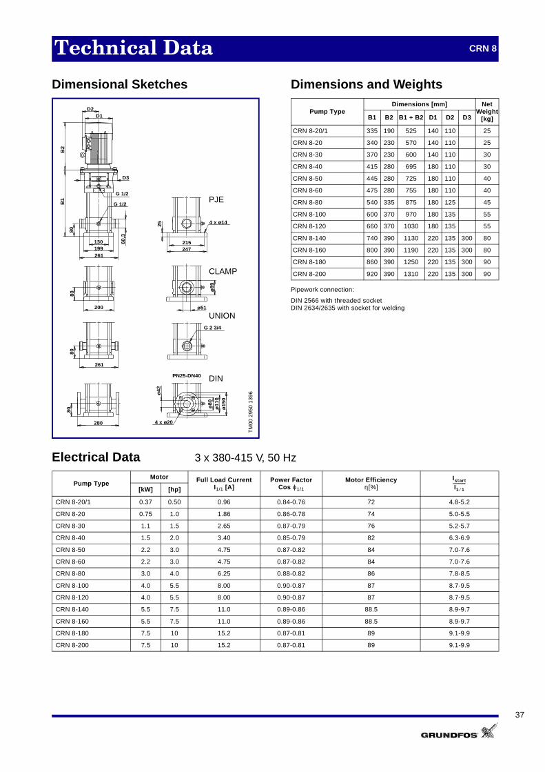
Technical Data CRN 8
Dimensional Sketches Dimensions and Weights
Pipework connection:
DIN 2566 with threaded socket DIN 2634/2635 with socket for welding
Electrical Data 3 x 380-415 V, 50 Hz
TM
00 2
950
1396
D3
G 1/2
130199261
B2
B1
60,3
80
25 4 x ø14
215247
280 4 x ø20
ø42
PN25-DN40
ø80
ø15
0
261
ø51200
G 2 3/4
8080
80
D2D1
G 1/2
ø11
0ø
89
UNION
DIN
CLAMP
PJE
Pump TypeDimensions [mm] Net
Weight[kg]B1 B2 B1 + B2 D1 D2 D3
CRN 8-20/1 335 190 525 140 110 25
CRN 8-20 340 230 570 140 110 25
CRN 8-30 370 230 600 140 110 30
CRN 8-40 415 280 695 180 110 30
CRN 8-50 445 280 725 180 110 40
CRN 8-60 475 280 755 180 110 40
CRN 8-80 540 335 875 180 125 45
CRN 8-100 600 370 970 180 135 55
CRN 8-120 660 370 1030 180 135 55
CRN 8-140 740 390 1130 220 135 300 80
CRN 8-160 800 390 1190 220 135 300 80
CRN 8-180 860 390 1250 220 135 300 90
CRN 8-200 920 390 1310 220 135 300 90
Pump TypeMotor Full Load Current
I1/1 [A]Power Factor
Cos ϕ1/1
Motor Efficiencyη[%][kW] [hp]
CRN 8-20/1 0.37 0.50 0.96 0.84-0.76 72 4.8-5.2
CRN 8-20 0.75 1.0 1.86 0.86-0.78 74 5.0-5.5
CRN 8-30 1.1 1.5 2.65 0.87-0.79 76 5.2-5.7
CRN 8-40 1.5 2.0 3.40 0.85-0.79 82 6.3-6.9
CRN 8-50 2.2 3.0 4.75 0.87-0.82 84 7.0-7.6
CRN 8-60 2.2 3.0 4.75 0.87-0.82 84 7.0-7.6
CRN 8-80 3.0 4.0 6.25 0.88-0.82 86 7.8-8.5
CRN 8-100 4.0 5.5 8.00 0.90-0.87 87 8.7-9.5
CRN 8-120 4.0 5.5 8.00 0.90-0.87 87 8.7-9.5
CRN 8-140 5.5 7.5 11.0 0.89-0.86 88.5 8.9-9.7
CRN 8-160 5.5 7.5 11.0 0.89-0.86 88.5 8.9-9.7
CRN 8-180 7.5 10 15.2 0.87-0.81 89 9.1-9.9
CRN 8-200 7.5 10 15.2 0.87-0.81 89 9.1-9.9
Istart
I1 1⁄------------

38
Performance Curves CRN 8-S
TM
00 3
158
3498
0 1 2 3 4 5 6 7 8 9 10 11 Q [m³/h]
0
10
20
30
40
50
60
70
80
90
100
110
120
130
140
150
160
170
180
190
200
210
220
H[m]
0.0 0.4 0.8 1.2 1.6 2.0 2.4 2.8 3.2 Q [l/s]
0.0
0.2
0.4
0.6
0.8
1.0
1.2
1.4
1.6
1.8
2.0
2.2[MPa]
p
CRN 8 S 50 Hz
ISO 2548 Annex B
-100 S
-120 S
-140 S
-160 S
-180 S
-200 S
0 1 2 3 4 5 6 7 8 9 10 11 Q [m³/h]
0.00.10.20.30.40.5
P2[kW]
010203040506070[%]Eta
0.0
0.2
0.4
0.6
0.8[hp]P2
eta
P2
0 1 2 3 4 5 6 7 8 9 10 11 Q [m³/h]
0
2
4
6
8
10
[m]H
0.0
0.4
0.8
1.2
1.6
2.0
NPSH[m]
0
40
80
[kPa]p
QH 2900 rpm
NPSH

39
Technical Data CRN 8-S
Dimensional Sketches Dimensions and Weights
Pipework connection:
DIN 2566 with threaded socketDIN 2634/2635 with socket for welding
Electrical Data 3 x 380-415 V, 50 Hz
TM
00 2
951
1396
PN25/DN40
D2D1
D3
B2
G 1/2
130199
261
60,3
80
25 4 x ø14
215
247
280 4 x ø20
ø42
ø15
0ø
110
80
G 1/2ø
80
B1
PJE
DIN
Pump TypeDimensions [mm] Net
Weight[kg]B1 B2 B1 + B2 D1 D2 D3
CRN 8-100 S 600 370 970 180 135 60
CRN 8-120 S 660 370 1030 180 135 60
CRN 8-140 S 740 390 1130 220 135 300 85
CRN 8-160 S 800 390 1190 220 135 300 85
CRN 8-180 S 860 390 1250 220 135 300 95
CRN 8-200 S 920 390 1310 220 135 300 95
Pump TypeMotor Full Load Current
I1/1 [A]Power Factor
Cos ϕ1/1
Motor Efficiencyη[%][kW] [hp]
CRN 8-100 S 4.0 5.5 8.00 0.90-0.87 87 8.7-9.5
CRN 8-120 S 4.0 5.5 8.00 0.90-0.87 87 8.7-9.5
CRN 8-140 S 5.5 7.5 11.0 0.89-0.86 88.5 8.9-9.7
CRN 8-160 S 5.5 7.5 11.0 0.89-0.86 88.5 8.9-9.7
CRN 8-180 S 7.5 10 15.2 0.87-0.81 89 9.1-9.9
CRN 8-200 S 7.5 10 15.2 0.87-0.81 89 9.1-9.9
Istart
I1 1⁄------------

40
Performance Curves CRN 8-SF
TM
00 3
691
4098
0 1 2 3 4 5 6 7 8 9 10 11 Q [m³/h]
100
120
140
160
180
200
220
240
260
280
300
320
340
360
380
400
420
H[m]
0.0 0.4 0.8 1.2 1.6 2.0 2.4 2.8 3.2 Q [l/s]
1.2
1.6
2.0
2.4
2.8
3.2
3.6
4.0
[MPa]p
CRN 8-200/19 SF +CRN 8-
50 Hz
CRN 8-200/19 SF
+CRN8-20
+CRN8-30
+CRN8-40
+CRN8-50
+CRN8-60
+CRN8-80
+CRN8-100
+CRN8-120
+CRN8-140
+CRN8-160
+CRN8-180
+CRN8-200 *
*
0 1 2 3 4 5 6 7 8 9 10 11 Q [m³/h]
0.0
0.1
0.2
0.3
0.4
0.5
P2[kW]
0.0
0.2
0.4
0.6
[hp]P2
0
10
20
30
40
50
60[%]Eta
P2
eta
41
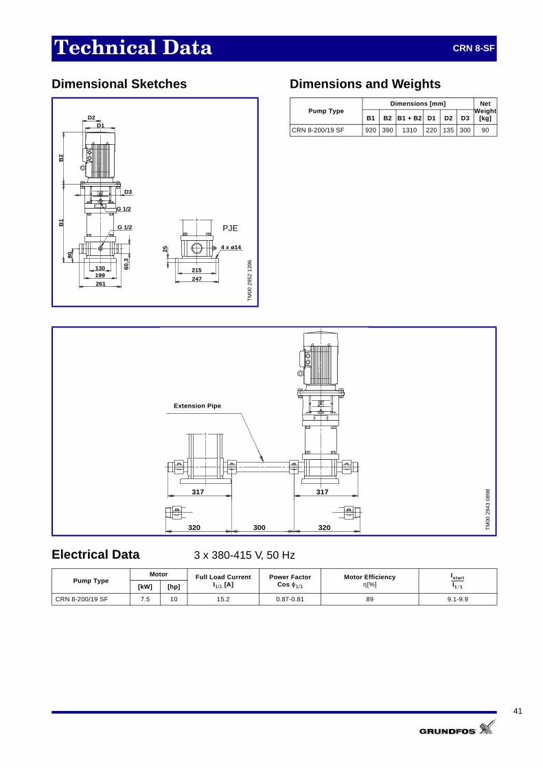
Technical Data CRN 8-SF
Dimensional Sketches Dimensions and Weights
Electrical Data 3 x 380-415 V, 50 Hz
TM
00 2
952
1396
D2D1
D3
B2
G 1/2
130199
261
60,3
80
25 4 x ø14
215
247
G 1/2
B1
PJE
Pump TypeDimensions [mm] Net
Weight[kg]B1 B2 B1 + B2 D1 D2 D3
CRN 8-200/19 SF 920 390 1310 220 135 300 90
TM
00 2
943
0898
Pump TypeMotor Full Load Current
I1/1 [A]Power Factor
Cos ϕ1/1
Motor Efficiencyη[%][kW] [hp]
CRN 8-200/19 SF 7.5 10 15.2 0.87-0.81 89 9.1-9.9
317 317
320 320300
Extension Pipe
Istart
I1 1⁄------------

42
Performance Curves CR 16
TM
00 0
415
5198
0 2 4 6 8 10 12 14 16 18 20 Q [m³/h]
0
10
20
30
40
50
60
70
80
90
100
110
120
130
140
150
160
170
180
190
200
210
220
H[m]
0.0 0.8 1.6 2.4 3.2 4.0 4.8 5.6 Q [l/s]
0.0
0.2
0.4
0.6
0.8
1.0
1.2
1.4
1.6
1.8
2.0
2.2[MPa]
p
CR 1650 Hz
ISO 2548 Annex B
-30/2
-30
-40
-50
-60
-70
-80
-100
-140
-160
-120
0 2 4 6 8 10 12 14 16 18 20 Q [m³/h]
0.0
0.4
0.8
1.2
P2[kW]
0
20
40
60
80[%]Eta
0.0
0.8
1.6
[hp]P2
eta
P2
0 2 4 6 8 10 12 14 16 18 20 Q [m³/h]
0
4
8
12
16[m]H
0
2
4
6
8
NPSH[m]
0
40
80
120
[kPa]p
QH 2900 rpm
NPSH

43
Technical Data CR 16
Dimensional Sketches Dimensions and Weights
Pipework connection:
DIN 2566 with threaded socket DIN 2634 with socket for welding
Electrical Data 3 x 380-415 V, 50 Hz
TM
00 3
112
3397
D2
D3
B2
B1
4 x ø13ø65
246
4 x ø18
ø16
5
ø12
5ø
102
215
20
PN25/DN50
90
300
130
G 1/2 Rp 1/4
G 1/2
190
D1
DIN
Pump TypeDimensions [mm] Net
Weight[kg]B1 B2 B1 + B2 D1 D2 D3
CR 16-30/2 460 280 740 180 110 50
CR 16-30 460 335 795 180 110 55
CR 16-40 505 370 875 180 135 60
CR 16-50 570 390 960 220 135 300 80
CR 16-60 615 390 1005 220 135 300 85
CR 16-70 660 390 1050 220 135 300 90
CR 16-80 705 390 1095 220 135 300 90
CR 16-100 825 465 1290 260 170 350 125
CR 16-120 915 465 1380 260 170 350 130
CR 16-140 1005 505 1510 325 250 350 175
CR 16-160 1095 505 1600 325 250 350 180
Pump TypeMotor Full Load Current
I1/1 [A]Power Factor
Cos ϕ1/1
Motor Efficiencyη[%][kW] [hp]
CR 16-30/2 2.2 3.0 4.75 0.87-0.82 84 7.0-7.6
CR 16-30 3.0 4.0 6.25 0.88-0.82 86 7.8-8.5
CR 16-40 4.0 5.5 8.00 0.90-0.87 87 8.7-9.5
CR 16-50 5.5 7.5 11.0 0.89-0.86 88.5 8.9-9.7
CR 16-60 5.5 7.5 11.0 0.89-0.86 88.5 8.9-9.7
CR 16-70 7.5 10 15.2 0.87-0.81 89 9.1-9.9
CR 16-80 7.5 10 15.2 0.87-0.81 89 9.1-9.9
CR 16-100 11 15 21.5 0.91-0.87 85 7.3-8.0
CR 16-120 11 15 21.5 0.91-0.87 85 7.3-8.0
CR 16-140 15 20 29.4-27.1 0.88 88.2-87.9 7.0-7.8
CR 16-160 15 20 29.4-27.1 0.88 88.2-87.9 7.0-7.8
Istart
I1 1⁄------------
44
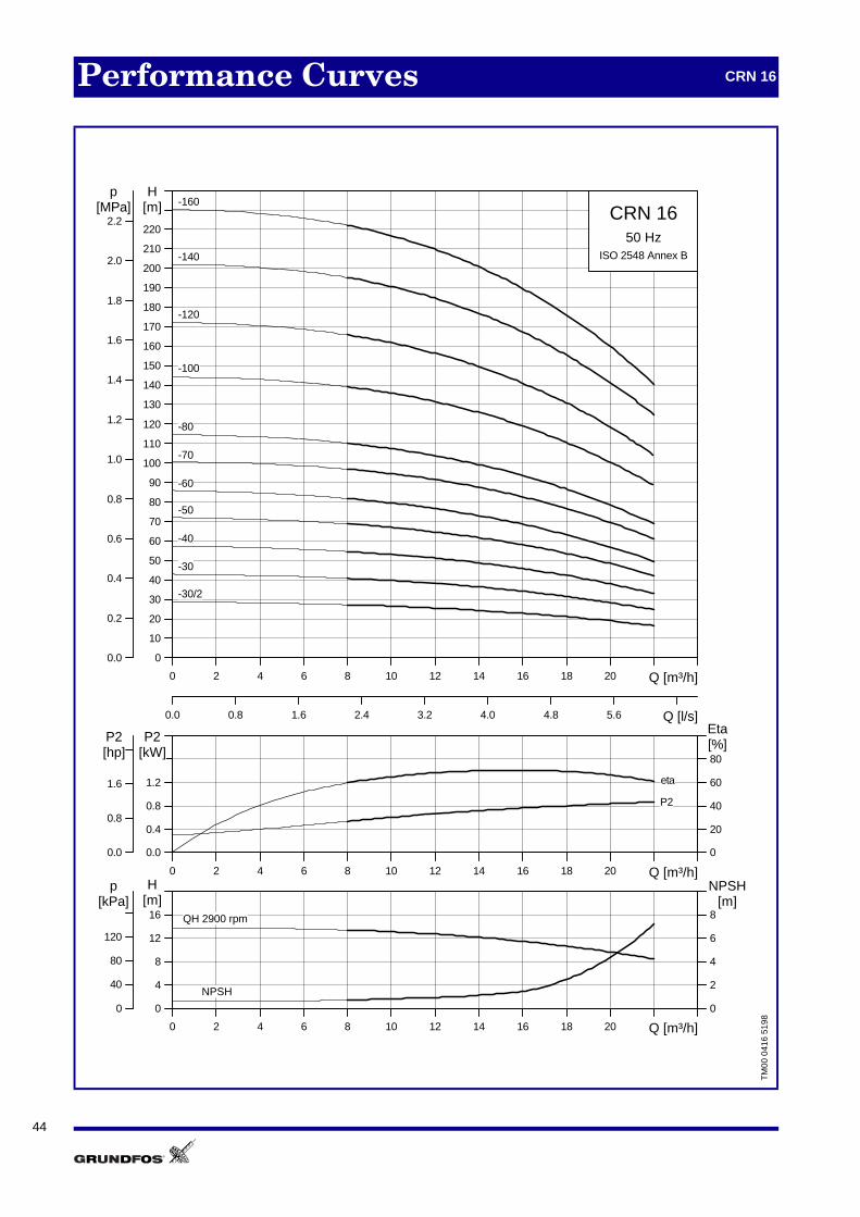
Performance Curves CRN 16
TM
00 0
416
5198
0 2 4 6 8 10 12 14 16 18 20 Q [m³/h]
0
10
20
30
40
50
60
70
80
90
100
110
120
130
140
150
160
170
180
190
200
210
220
H[m]
0.0 0.8 1.6 2.4 3.2 4.0 4.8 5.6 Q [l/s]
0.0
0.2
0.4
0.6
0.8
1.0
1.2
1.4
1.6
1.8
2.0
2.2[MPa]
p
CRN 1650 Hz
ISO 2548 Annex B
-30/2
-30
-40
-50
-60
-70
-80
-100
-140
-160
-120
0 2 4 6 8 10 12 14 16 18 20 Q [m³/h]
0.0
0.4
0.8
1.2
P2[kW]
0
20
40
60
80[%]Eta
0.0
0.8
1.6
[hp]P2
eta
P2
0 2 4 6 8 10 12 14 16 18 20 Q [m³/h]
0
4
8
12
16[m]H
0
2
4
6
8
NPSH[m]
0
40
80
120
[kPa]p
QH 2900 rpm
NPSH
45
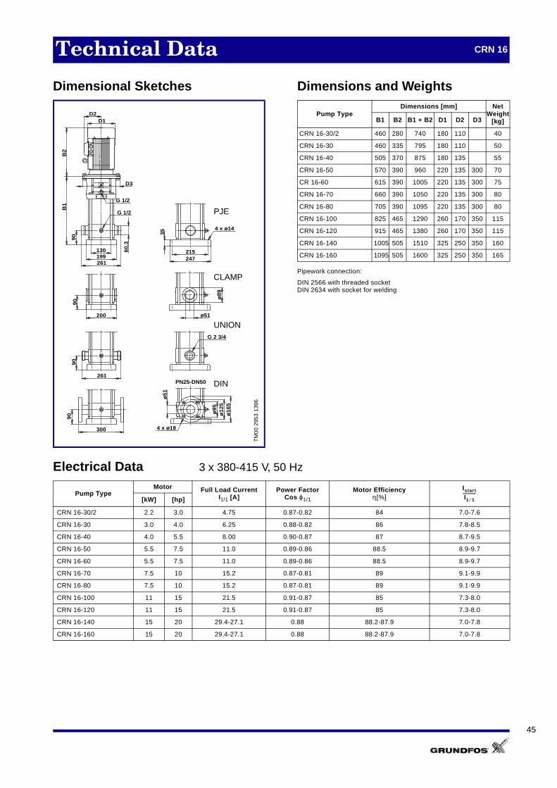
Technical Data CRN 16
Dimensional Sketches Dimensions and Weights
Pipework connection:
DIN 2566 with threaded socketDIN 2634 with socket for welding
Electrical Data 3 x 380-415 V, 50 Hz
TM
00 2
953
1396
60,3
90
G 1/2
130199261
G 1/2
B1
D3
D2D1
B2
35
4 x ø14
215247
90
300
PN25-DN50
ø12
5ø
165
ø95
ø51
4 x ø18
ø89
ø51200
90
261
90
G 2 3/4
UNION
PJE
CLAMP
DIN
Pump TypeDimensions [mm] Net
Weight[kg]B1 B2 B1 + B2 D1 D2 D3
CRN 16-30/2 460 280 740 180 110 40
CRN 16-30 460 335 795 180 110 50
CRN 16-40 505 370 875 180 135 55
CRN 16-50 570 390 960 220 135 300 70
CR 16-60 615 390 1005 220 135 300 75
CRN 16-70 660 390 1050 220 135 300 80
CRN 16-80 705 390 1095 220 135 300 80
CRN 16-100 825 465 1290 260 170 350 115
CRN 16-120 915 465 1380 260 170 350 115
CRN 16-140 1005 505 1510 325 250 350 160
CRN 16-160 1095 505 1600 325 250 350 165
Pump TypeMotor Full Load Current
I1/1 [A]Power Factor
Cos ϕ1/1
Motor Efficiencyη[%][kW] [hp]
CRN 16-30/2 2.2 3.0 4.75 0.87-0.82 84 7.0-7.6
CRN 16-30 3.0 4.0 6.25 0.88-0.82 86 7.8-8.5
CRN 16-40 4.0 5.5 8.00 0.90-0.87 87 8.7-9.5
CRN 16-50 5.5 7.5 11.0 0.89-0.86 88.5 8.9-9.7
CRN 16-60 5.5 7.5 11.0 0.89-0.86 88.5 8.9-9.7
CRN 16-70 7.5 10 15.2 0.87-0.81 89 9.1-9.9
CRN 16-80 7.5 10 15.2 0.87-0.81 89 9.1-9.9
CRN 16-100 11 15 21.5 0.91-0.87 85 7.3-8.0
CRN 16-120 11 15 21.5 0.91-0.87 85 7.3-8.0
CRN 16-140 15 20 29.4-27.1 0.88 88.2-87.9 7.0-7.8
CRN 16-160 15 20 29.4-27.1 0.88 88.2-87.9 7.0-7.8
Istart
I1 1⁄------------

46
Performance Curves CRN 16-S
TM
00 3
159
5198
0 2 4 6 8 10 12 14 16 18 20 Q [m³/h]
0
10
20
30
40
50
60
70
80
90
100
110
120
130
140
150
160
170
180
190
200
210
220
H[m]
0.0 0.8 1.6 2.4 3.2 4.0 4.8 5.6 Q [l/s]
0.0
0.2
0.4
0.6
0.8
1.0
1.2
1.4
1.6
1.8
2.0
2.2[MPa]
p
CRN 16 S 50 Hz
ISO 2548 Annex B
-70 S
-80 S
-100 S
-140 S
-160 S
-120 S
0 2 4 6 8 10 12 14 16 18 20 22Q [m³/h]
0.0
0.4
0.8
1.2
P2[kW]
0
20
40
60
80[%]Eta
0.0
0.8
1.6
[hp]P2
eta
P2
0 2 4 6 8 10 12 14 16 18 20 22Q [m³/h]
0
4
8
12
16[m]H
0
2
4
6
NPSH[m]
0
40
80
120
160[kPa]
p
QH 2900 rpm
NPSH

47
Technical Data CRN 16-S
Dimensional Sketches Dimensions and Weights
Pipework connection:
DIN 2566 with threaded socket DIN 2634 with socket for welding
Electrical Data 3 x 380-415 V, 50 Hz
TM
00 2
954
1396
G 1/2
D2D1
B2
300
ø12
5ø
165
ø95
ø51
4 x ø18
35
4 x ø14
215247199
60,
39090
PN25/DN50
B1
D3
G 1/2
261
130
DIN
PJE
Pump TypeDimensions [mm] Net
Weight[kg]B1 B2 B1 + B2 D1 D2 D3
CRN 16-70 S 660 390 1050 220 135 300 85
CRN 16-80 S 705 390 1095 220 135 300 85
CRN 16-100 S 825 465 1290 260 170 350 120
CRN 16-120 S 915 465 1380 260 170 350 120
CRN 16-140 S 1005 505 1510 325 250 350 165
CRN 16-160 S 1095 505 1600 325 250 350 170
Pump TypeMotor Full Load Current
I1/1 [A]Power Factor
Cos ϕ1/1
Motor Efficiencyη[%][kW] [hp]
CRN 16-70 S 7.5 10 15.2 0.87-0.81 89 9.1-9.9
CRN 16-80 S 7.5 10 15.2 0.87-0.81 89 9.1-9.9
CRN 16-100 S 11 15 21.5 0.91-0.87 85 7.3-8.0
CRN 16-120 S 11 15 21.5 0.91-0.87 85 7.3-8.0
CRN 16-140 S 15 20 29.4-27.1 0.88 88.2-87.9 7.0-7.8
CRN 16-160 S 15 20 29.4-27.1 0.88 88.2-87.9 7.0-7.8
Istart
I1 1⁄------------

48
Performanc Curves CRN 16-SF
TM
00 3
692
4098
0 2 4 6 8 10 12 14 16 18 20 Q [m³/h]
100
120
140
160
180
200
220
240
260
280
300
320
340
360
380
400
420
440
H[m]
0.0 0.8 1.6 2.4 3.2 4.0 4.8 5.6 Q [l/s]
1.2
1.6
2.0
2.4
2.8
3.2
3.6
4.0
[MPa]p
CRN 16-160/15 SF +CRN 16-
50 Hz
CRN16-160/15 SF
+CRN16-30/2
+CRN16-30
+CRN16-40
+CRN16-50
+CRN16-60
+CRN16-70
+CRN16-80
+CRN16-100
+CRN16-120
+CRN16-140
+CRN16-160 *
*
0 2 4 6 8 10 12 14 16 18 20 Q [m³/h]
0.0
0.2
0.4
0.6
0.8
1.0
1.2
P2[kW]
0.0
0.4
0.8
1.2
1.6
[hp]P2
0
10
20
30
40
50
60
70[%]Eta
P2
eta

49
Technical Data CRN 16-SF
Dimensional Sketches Dimensions and Weights
Electrical Data 3 x 380-415 V, 50 Hz
TM
00 2
955
1396
G 1/2
D2D1
B2
35
4 x ø14
215247199
60,
390
B1
D3
G 1/2
261
130
PJE
Pump TypeDimensions [mm] Net
Weight[kg]B1 B2 B1 + B2 D1 D2 D3
CRN 16-160/15 SF 1095 505 1600 325 250 350 165
TM
00 2
943
0898
Pump TypeMotor Full Load Current
I1/1 [A]Power Factor
Cos ϕ1/1
Motor Efficiencyη[%][kW] [hp]
CRN 16-160/15 SF 15 20 29.4-27.1 0.88 88.2-87.9 7.0-7.8
317 317
320 320300
Extension Pipe
Istart
I1 1⁄------------

50
Performance Curves CR 32
TM
01 1
449
3498
0 4 8 12 16 20 24 28 32 36 Q [m³/h]
0
20
40
60
80
100
120
140
160
180
200
220
240
260
280
H[m]
0 2 4 6 8 10 Q [l/s]
0.0
0.4
0.8
1.2
1.6
2.0
2.4
[MPa]p
CR 3250 Hz
ISO 2548 Annex B
-11-11-2
-12-12-2
-13-13-2
-14-14-2
-1-1-1
-10-10-2
-2-2-2
-3-3-2
-4-4-2
-5-5-2
-6-6-2
-7-7-2
-8-8-2
-9-9-2
0 4 8 12 16 20 24 28 32 36 40Q [m³/h]
0.0
0.6
1.2
1.8
P2[kW]
0
20
40
60
80[%]Eta
0.0
0.8
1.6
2.4
[hp]P2
P2 1/1P2 2/3
eta
0 4 8 12 16 20 24 28 32 36 Q [m³/h]
0
4
8
12
16
20
[m]H
0
2
4
6
8
NPSH[m]
0
40
80
120
160
[kPa]p
QH 2900 rpm 1/1
QH 2900 rpm 2/3
NPSH

51
Technical Data CR 32
Dimensional Sketches Dimensions and Weights
Electrical Data 3 x 380-415 V, 50 Hz
TM
01 1
749
5197
ø74240298
ø107
ø145
ø185
D2D1
170223320
B1
B2
G 1/2 8 x ø18
G 1/2
G 1/2
4 x ø14
105
D3
30
PN16-25-40/DN65
Pump TypeDimensions [mm] Net
Weight[kg]B1 B2 B1 + B2 D1 D2 D3
CR 32-1-1 505 281 786 178 110 135 70CR 32-1 505 281 786 178 110 135 79CR 32-2-2 575 335 910 178 110 143 89CR 32-2 575 372 947 220 134 158 98CR 32-3-2 645 391 1036 220 134 298 107CR 32-3 645 391 1036 220 134 298 107CR 32-4-2 715 391 1106 220 134 298 115CR 32-4 715 391 1106 220 134 298 115CR 32-5-2 895 464 1359 260 172 350 156CR 32-5 895 464 1359 260 172 350 156CR 32-6-2 965 464 1429 260 172 350 160CR 32-6 965 464 1429 260 172 350 160CR 32-7-2 1035 478 1513 306 197 350 197CR 32-7 1035 478 1513 306 197 350 197CR 32-8-2 1105 478 1583 306 197 350 201CR 32-8 1105 478 1583 306 197 350 201CR 32-9-2 1175 478 1653 306 197 350 215CR 32-9 1175 478 1653 306 197 350 215CR 32-10-2 1245 478 1723 306 197 350 219CR 32-10 1245 478 1723 306 197 350 219CR 32-11-2 1315 600 1915 364 269 350 276CR 32-11 1315 600 1915 364 269 350 276CR 32-12-2 1385 600 1985 364 269 350 280CR 32-12 1385 600 1985 364 269 350 280CR 32-13-2 1455 667 2122 404 306 400 362CR 32-13 1455 667 2122 404 306 400 362CR 32-14-2 1525 667 2192 404 306 400 366CR 32-14 1525 667 2192 404 306 400 366
Pump TypeMotor Full Load Current
I1/1 [A]Power Factor
Cos ϕ1/1
Motor Efficiencyη[%][kW] [hp]
CR 32-1-1 1.5 2.0 3.40 0.85-0.79 82.0 6.3-6.9CR 32-1 2.2 3.0 4.75 0.87-0.82 84.0 7.0-7.6CR 32-2-2 3.0 4.0 6.25 0.88-0.82 86.0 7.8-8.5CR 32-2 4.0 5.5 8.00 0.90-0.87 87.0 8.7-9.5CR 32-3-2 5.5 7.5 11.0 0.89-0.86 88.5 8.9-9.7CR 32-3 5.5 7.5 11.0 0.89-0.86 88.5 8.9-9.7CR 32-4-2 7.5 10 15.2 0.87-0.81 89.0 9.1-9.9CR 32-4 7.5 10 15.2 0.87-0.81 89.0 9.1-9.9CR 32-5-2 11 15 21.5 0.91-0.87 85.0 7.3-8.0CR 32-5 11 15 21.5 0.91-0.87 85.0 7.3-8.0CR 32-6-2 11 15 21.5 0.91-0.87 85.0 7.3-8.0CR 32-6 11 15 21.5 0.91-0.87 85.0 7.3-8.0CR 32-7-2 15 20 28.7 0.87 86.0 6.0CR 32-7 15 20 28.7 0.87 86.0 6.0CR 32-8-2 15 20 28.7 0.87 86.0 6.0CR 32-8 15 20 28.7 0.87 86.0 6.0CR 32-9-2 18.5 25 35.9-34.1 0.86 87.0 7.2CR 32-9 18.5 25 35.9-34.1 0.86 87.0 7.2CR 32-10-2 18.5 25 35.9-34.1 0.86 87.0 7.2CR 32-10 18.5 25 35.9-34.1 0.86 87.0 7.2CR 32-11-2 22 30 42.0-40.0 0.86 89.2 7.3CR 32-11 22 30 42.0-40.0 0.86 89.2 7.3CR 32-12-2 22 30 42.0-40.0 0.86 89.2 7.3CR 32-12 22 30 42.0-40.0 0.86 89.2 7.3CR 32-13-2 30 40 56.0-52.0 0.88 91.7 7.5CR 32-13 30 40 56.0-52.0 0.88 91.7 7.5CR 32-14-2 30 40 56.0-52.0 0.88 91.7 7.5CR 32-14 30 40 56.0-52.0 0.88 91.7 7.5
Istart
I1 1⁄------------

52
Performance Curves CRN 32
TM
01 1
450
3498
0 4 8 12 16 20 24 28 32 36 Q [m³/h]
0
20
40
60
80
100
120
140
160
180
200
220
240
260
280
H[m]
0 2 4 6 8 10 Q [l/s]
0.0
0.4
0.8
1.2
1.6
2.0
2.4
[MPa]p
CRN 3250 Hz
ISO 2548 Annex B
-11-11-2
-12-12-2
-13-13-2
-14-14-2
-1-1-1
-10-10-2
-2-2-2
-3-3-2
-4-4-2
-5-5-2
-6-6-2
-7-7-2
-8-8-2
-9-9-2
0 4 8 12 16 20 24 28 32 36 Q [m³/h]
0.0
0.6
1.2
1.8
P2[kW]
0
20
40
60
80[%]Eta
0.0
0.8
1.6
2.4
[hp]P2
P2 1/1P2 2/3
eta
0 4 8 12 16 20 24 28 32 36 Q [m³/h]
0
4
8
12
16
20
[m]H
0
2
4
6
8
NPSH[m]
0
40
80
120
160
[kPa]p
QH 2900 rpm 1/1
QH 2900 rpm 2/3
NPSH
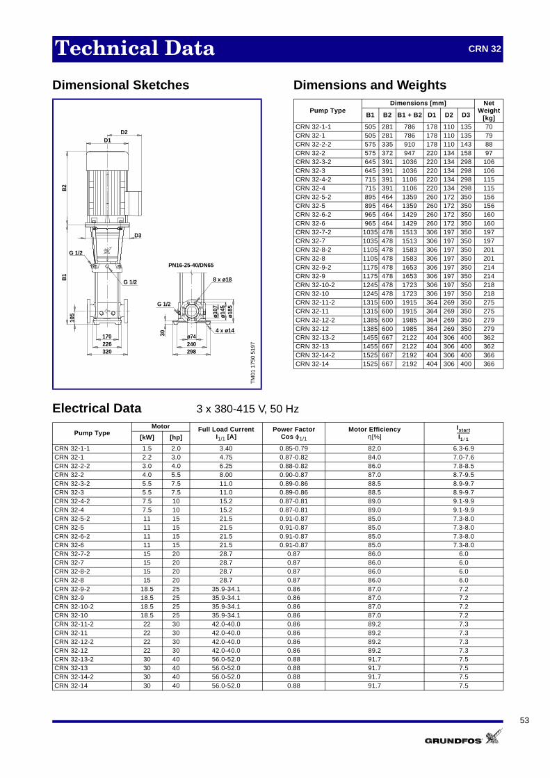
53
Technical Data CRN 32
Dimensional Sketches Dimensions and Weights
Electrical Data 3 x 380-415 V, 50 Hz
TM
01 1
750
5197
8 x ø18
G 1/2
ø74240298
ø107
ø145
ø185
D2D1
170226320
B1
B2
G 1/2
G 1/2
4 x ø14
105
D3
30
PN16-25-40/DN65
Pump TypeDimensions [mm] Net
Weight[kg]B1 B2 B1 + B2 D1 D2 D3
CRN 32-1-1 505 281 786 178 110 135 70CRN 32-1 505 281 786 178 110 135 79CRN 32-2-2 575 335 910 178 110 143 88CRN 32-2 575 372 947 220 134 158 97CRN 32-3-2 645 391 1036 220 134 298 106CRN 32-3 645 391 1036 220 134 298 106CRN 32-4-2 715 391 1106 220 134 298 115CRN 32-4 715 391 1106 220 134 298 115CRN 32-5-2 895 464 1359 260 172 350 156CRN 32-5 895 464 1359 260 172 350 156CRN 32-6-2 965 464 1429 260 172 350 160CRN 32-6 965 464 1429 260 172 350 160CRN 32-7-2 1035 478 1513 306 197 350 197CRN 32-7 1035 478 1513 306 197 350 197CRN 32-8-2 1105 478 1583 306 197 350 201CRN 32-8 1105 478 1583 306 197 350 201CRN 32-9-2 1175 478 1653 306 197 350 214CRN 32-9 1175 478 1653 306 197 350 214CRN 32-10-2 1245 478 1723 306 197 350 218CRN 32-10 1245 478 1723 306 197 350 218CRN 32-11-2 1315 600 1915 364 269 350 275CRN 32-11 1315 600 1915 364 269 350 275CRN 32-12-2 1385 600 1985 364 269 350 279CRN 32-12 1385 600 1985 364 269 350 279CRN 32-13-2 1455 667 2122 404 306 400 362CRN 32-13 1455 667 2122 404 306 400 362CRN 32-14-2 1525 667 2192 404 306 400 366CRN 32-14 1525 667 2192 404 306 400 366
Pump TypeMotor Full Load Current
I1/1 [A]Power Factor
Cos ϕ1/1
Motor Efficiencyη[%][kW] [hp]
CRN 32-1-1 1.5 2.0 3.40 0.85-0.79 82.0 6.3-6.9CRN 32-1 2.2 3.0 4.75 0.87-0.82 84.0 7.0-7.6CRN 32-2-2 3.0 4.0 6.25 0.88-0.82 86.0 7.8-8.5CRN 32-2 4.0 5.5 8.00 0.90-0.87 87.0 8.7-9.5CRN 32-3-2 5.5 7.5 11.0 0.89-0.86 88.5 8.9-9.7CRN 32-3 5.5 7.5 11.0 0.89-0.86 88.5 8.9-9.7CRN 32-4-2 7.5 10 15.2 0.87-0.81 89.0 9.1-9.9CRN 32-4 7.5 10 15.2 0.87-0.81 89.0 9.1-9.9CRN 32-5-2 11 15 21.5 0.91-0.87 85.0 7.3-8.0CRN 32-5 11 15 21.5 0.91-0.87 85.0 7.3-8.0CRN 32-6-2 11 15 21.5 0.91-0.87 85.0 7.3-8.0CRN 32-6 11 15 21.5 0.91-0.87 85.0 7.3-8.0CRN 32-7-2 15 20 28.7 0.87 86.0 6.0CRN 32-7 15 20 28.7 0.87 86.0 6.0CRN 32-8-2 15 20 28.7 0.87 86.0 6.0CRN 32-8 15 20 28.7 0.87 86.0 6.0CRN 32-9-2 18.5 25 35.9-34.1 0.86 87.0 7.2CRN 32-9 18.5 25 35.9-34.1 0.86 87.0 7.2CRN 32-10-2 18.5 25 35.9-34.1 0.86 87.0 7.2CRN 32-10 18.5 25 35.9-34.1 0.86 87.0 7.2CRN 32-11-2 22 30 42.0-40.0 0.86 89.2 7.3CRN 32-11 22 30 42.0-40.0 0.86 89.2 7.3CRN 32-12-2 22 30 42.0-40.0 0.86 89.2 7.3CRN 32-12 22 30 42.0-40.0 0.86 89.2 7.3CRN 32-13-2 30 40 56.0-52.0 0.88 91.7 7.5CRN 32-13 30 40 56.0-52.0 0.88 91.7 7.5CRN 32-14-2 30 40 56.0-52.0 0.88 91.7 7.5CRN 32-14 30 40 56.0-52.0 0.88 91.7 7.5
Istart
I1 1⁄------------
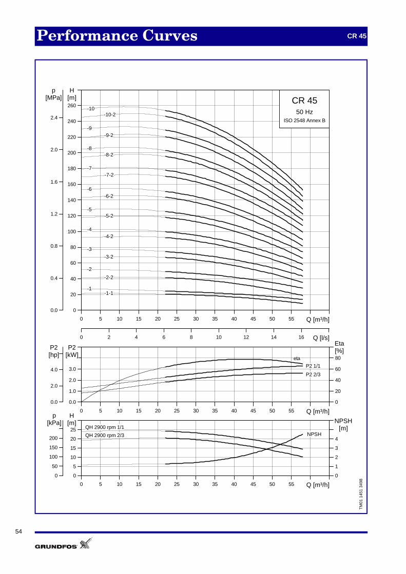
54
Performance Curves CR 45
TM
01 1
451
3498
0 5 10 15 20 25 30 35 40 45 50 55 Q [m³/h]
0
20
40
60
80
100
120
140
160
180
200
220
240
260
H[m]
0 2 4 6 8 10 12 14 16 Q [l/s]
0.0
0.4
0.8
1.2
1.6
2.0
2.4
[MPa]p
CR 4550 Hz
ISO 2548 Annex B
-1-1
-10-10-2
-2
-2-2
-3
-3-2
-4-4-2
-5-5-2
-6-6-2
-7-7-2
-8-8-2
-9-9-2
-1
0 5 10 15 20 25 30 35 40 45 50 55 Q [m³/h]
0.0
1.0
2.0
3.0
P2[kW]
0
20
40
60
80[%]Eta
0.0
2.0
4.0
[hp]P2
P2 1/1
P2 2/3
eta
0 5 10 15 20 25 30 35 40 45 50 55 Q [m³/h]
0
5
10
15
20
25[m]H
0
1
2
3
4
NPSH[m]
0
50
100
150
200
[kPa]p
QH 2900 rpm 1/1
QH 2900 rpm 2/3 NPSH

55
Technical Data CR 45
Dimensional Sketches Dimensions and Weights
Electrical Data 3 x 380-415 V, 50 Hz
TM
01 1
751
5197
8 x ø18
G 1/2
ø80266331
ø120
ø160
ø200
D2D1
190248365
B1
B2
G 1/2
G 1/2
4 x ø14
140
D3
45
PN16-25/DN80
Pump TypeDimensions [mm] Net
Weight[kg]B1 B2 B1 + B2 D1 D2 D3
CR 45-1-1 558 335 893 178 110 135 95
CR 45-1 558 372 930 220 134 158 104
CR 45-2-2 638 391 1029 220 134 298 113
CR 45-2 638 391 1029 220 134 298 118
CR 45-3-2 828 464 1292 260 172 350 159
CR 45-3 828 464 1292 260 172 350 159
CR 45-4-2 908 478 1386 306 197 350 196
CR 45-4 908 478 1386 306 197 350 196
CR 45-5-2 988 478 1466 306 197 350 210
CR 45-5 988 478 1466 306 197 350 210
CR 45-6-2 1068 600 1668 364 269 350 267
CR 45-6 1068 600 1668 364 269 350 267
CR 45-7-2 1148 667 1815 404 306 400 350
CR 45-7 1148 667 1815 404 306 400 350
CR 45-8-2 1228 667 1895 404 306 400 354
CR 45-8 1228 667 1895 404 306 400 354
CR 45-9-2 1308 667 1975 404 306 400 358
CR 45-9 1308 667 1975 404 306 400 358
CR 45-10-2 1388 667 2055 404 306 400 382
CR 45-10 1388 715 2103 404 306 400 382
Pump TypeMotor Full Load Current
I1/1 [A]Power Factor
Cos ϕ1/1
Motor Efficiencyη[%][kW] [hp]
CR 45-1-1 3.0 4.0 6.25 0.88-0.82 86.0 7.8-8.5CR 45-1 4.0 5.5 8.00 0.90-0.87 87.0 8.7-9.5CR 45-2-2 5.5 7.5 11.0 0.89-0.86 88.5 8.9-9.7CR 45-2 7.5 10 15.2 0.87-0.81 89.0 9.1-9.9CR 45-3-2 11 15 21.5 0.91-0.87 85.0 7.3-8.0CR 45-3 11 15 21.5 0.91-0.87 85.0 7.3-8.0CR 45-4-2 15 20 28.7 0.87 86.0 6.0CR 45-4 15 20 28.7 0.87 86.0 6.0CR 45-5-2 18.5 25 35.9-34.1 0.86 87.0 7.2CR 45-5 18.5 25 35.9-34.1 0.86 87.0 7.2CR 45-6-2 22 30 42.0-40.0 0.86 89.2 7.3CR 45-6 22 30 42.0-40.0 0.86 89.2 7.3CR 45-7-2 30 40 56.0-52.0 0.88 91.7 7.5CR 45-7 30 40 56.0-52.0 0.88 91.7 7.5CR 45-8-2 30 40 56.0-52.0 0.88 91.7 7.5CR 45-8 30 40 56.0-52.0 0.88 91.7 7.5CR 45-9-2 30 40 56.0-52.0 0.88 91.7 7.5CR 45-9 37 50 68.0-63.0 0.89 92.4 7.8CR 45-10-2 37 50 68.0-63.0 0.89 92.4 7.8CR 45-10 37 50 68.0-63.0 0.89 92.4 7.8
Istart
I1 1⁄------------

56
Performance Curves CRN 45
TM
01 1
452
3498
0 5 10 15 20 25 30 35 40 45 50 55 Q [m³/h]
0
20
40
60
80
100
120
140
160
180
200
220
240
260
H[m]
0 2 4 6 8 10 12 14 16 Q [l/s]
0.0
0.4
0.8
1.2
1.6
2.0
2.4
[MPa]p
CRN 4550 Hz
ISO 2548 Annex B
-1-1
-10-10-2
-2
-2-2
-3
-3-2
-4-4-2
-5-5-2
-6-6-2
-7-7-2
-8-8-2
-9-9-2
-1
0 5 10 15 20 25 30 35 40 45 50 55 Q [m³/h]
0.0
1.0
2.0
3.0
P2[kW]
0
20
40
60
80[%]Eta
0.0
2.0
4.0
[hp]P2
P2 1/1
P2 2/3
eta
0 5 10 15 20 25 30 35 40 45 50 55 Q [m³/h]
0
5
10
15
20
25[m]H
0
1
2
3
4
NPSH[m]
0
50
100
150
200
[kPa]p
QH 2900 rpm 1/1
QH 2900 rpm 2/3 NPSH

57
Technical Data CRN 45
Dimensional Sketches Dimensions and Weights
Electrical Data 3 x 380-415 V, 50 Hz
TM
01 1
752
5197
ø80266331
ø120
ø160
ø200
D2D1
190251365
B1
B2
G 1/2 8 x ø18
G 1/2
4 x ø14
140
D3
45
G 1/2
PN16-25/DN80
Pump TypeDimensions [mm] Net
Weight[kg]B1 B2 B1 + B2 D1 D2 D3
CRN 45-1-1 558 335 893 178 110 135 94CRN 45-1 558 372 930 220 134 158 103CRN 45-2-2 638 391 1029 220 134 298 112CRN 45-2 638 377 1015 220 148 300 117CRN 45-3-2 828 464 1292 260 172 350 158CRN 45-3 828 464 1292 260 172 350 158CRN 45-4-2 908 478 1386 306 197 350 196CRN 45-4 908 478 1386 306 197 350 196CRN 45-5-2 988 478 1466 306 197 350 209CRN 45-5 988 478 1466 306 197 350 209CRN 45-6-2 1068 600 1668 364 269 350 266CRN 45-6 1068 600 1668 364 269 350 266CRN 45-7-2 1148 667 1815 404 306 400 349CRN 45-7 1148 667 1815 404 306 400 349CRN 45-8-2 1228 667 1895 404 306 400 353CRN 45-8 1228 667 1895 404 306 400 353CRN 45-9-2 1308 667 1975 404 306 400 358CRN 45-9 1308 667 1975 404 306 400 358CRN 45-10-2 1388 667 2055 404 306 400 382CRN 45-10 1388 667 2055 404 306 400 382
Pump TypeMotor Full Load Current
I1/1 [A]Power Factor
Cos ϕ1/1
Motor Efficiencyη[%][kW] [hp]
CRN 45-1-1 3.0 4.0 6.25 0.88-0.82 86.0 7.8-8.5CRN 45-1 4.0 5.5 8.00 0.90-0.87 87.0 8.7-9.5CRN 45-2-2 5.5 7.5 11.0 0.89-0.86 88.5 8.9-9.7CRN 45-2 7.5 10 15.2 0.87-0.81 89.0 9.1-9.9CRN 45-3-2 11 15 21.5 0.91-0.87 85.0 7.3-8.0CRN 45-3 11 15 21.5 0.91-0.87 85.0 7.3-8.0CRN 45-4-2 15 20 28.7 0.87 86.0 6.0CRN 45-4 15 20 28.7 0.87 86.0 6.0CRN 45-5-2 18.5 25 35.9-34.1 0.86 87.0 7.2CRN 45-5 18.5 25 35.9-34.1 0.86 87.0 7.2CRN 45-6-2 22 30 42.0-40.0 0.86 89.2 7.3CRN 45-6 22 30 42.0-40.0 0.86 89.2 7.3CRN 45-7-2 30 40 56.0-52.0 0.88 91.7 7.5CRN 45-7 30 40 56.0-52.0 0.88 91.7 7.5CRN 45-8-2 30 40 56.0-52.0 0.88 91.7 7.5CRN 45-8 30 40 56.0-52.0 0.88 91.7 7.5CRN 45-9-2 30 40 56.0-52.0 0.88 91.7 7.5CRN 45-9 37 50 68.0-63.0 0.89 92.4 7.8CRN 45-10-2 37 50 68.0-63.0 0.89 92.4 7.8CRN 45-10 37 50 68.0-63.0 0.89 92.4 7.8
Istart
I1 1⁄------------
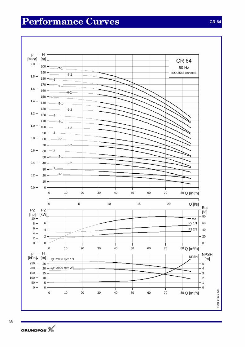
58
Performance Curves CR 64
TM
01 1
453
3498
0 10 20 30 40 50 60 70 80 Q [m³/h]
0
10
20
30
40
50
60
70
80
90
100
110
120
130
140
150
160
170
180
190
200
H[m]
0 5 10 15 20 Q [l/s]
0.0
0.2
0.4
0.6
0.8
1.0
1.2
1.4
1.6
1.8
2.0
[MPa]p
CR 6450 Hz
ISO 2548 Annex B
-1
-2
-2-1
-2-2
-3
-3-1
-3-2
-4
-4-1
-4-2
-5
-5-1
-5-2
-6
-6-1
-6-2
-7-1
-7-2
-1-1
0 10 20 30 40 50 60 70 80 Q [m³/h]
0
2
4
6
P2[kW]
0
20
40
60
80[%]Eta
0
2
4
6
8
10[hp]P2
P2 1/1
P2 2/3
eta
0 10 20 30 40 50 60 70 80 Q [m³/h]
0
5
10
15
20
25
[m]H
0
1
2
3
4
5
NPSH[m]
0
50
100
150
200
250
[kPa]p
QH 2900 rpm 1/1
QH 2900 rpm 2/3
NPSH

59
Technical Data CR 64
Dimensional Sketches Dimensions and Weights
Electrical Data 3 x 380-415 V, 50 Hz
TM
01 1
753
5197
ø100266331
ø150
ø180
ø220
D2D1
190248365
B1
B2
G 1/2 8 x ø18
G 1/2
G 1/2
4 x ø14
140
D3
45
PN16/DN100
PN25/DN10045
4 x ø14
G 1/2
8 x ø22
ø235
ø190
ø150
331266ø100
Pump TypeDimensions [mm] Net
Weight[kg]B1 B2 B1 + B2 D1 D2 D3
CR 64-1-1 561 372 933 220 134 158 107
CR 64-1 561 391 952 220 134 298 112
CR 64-2-2 644 391 1035 220 134 298 121
CR 64-2-1 754 464 1218 260 172 350 158
CR 64-2 754 464 1218 260 172 350 158
CR 64-3-2 836 478 1314 306 197 350 196
CR 64-3-1 836 478 1314 306 197 350 196
CR 64-3 836 478 1314 306 197 350 205
CR 64-4-2 919 478 1397 306 197 350 209
CR 64-4-1 919 600 1519 364 269 350 262
CR 64-4 919 600 1519 364 269 350 262
CR 64-5-2 1001 667 1668 404 306 400 345
CR 64-5-1 1001 667 1668 404 306 400 345
CR 64-5 1001 667 1668 404 306 400 345
CR 64-6-2 1084 667 1751 404 306 400 350
CR 64-6-1 1084 667 1751 404 306 400 370
CR 64-6 1084 667 1751 404 306 400 370
CR 64-7-2 1166 667 1833 404 306 400 374
CR 64-7-1 1166 667 1833 404 306 400 374
Pump TypeMotor Full Load Current
I1/1 [A]Power Factor
Cos ϕ1/1
Motor Efficiencyη[%][kW] [hp]
CR 64-1-1 4.0 5.5 8.00 0.90-0.87 87.0 8.7-9.5CR 64-1 5.5 7.5 11.0 0.89-0.86 88.5 8.9-9.7CR 64-2-2 7.5 10 15.2 0.87-0.81 89.0 9.1-9.9CR 64-2-1 11 15 21.5 0.91-0.87 85.0 7.3-8.0CR 64-2 11 15 21.5 0.91-0.87 85.0 7.3-8.0CR 64-3-2 15 20 28.7 0.87 86.0 6.0CR 64-3-1 15 20 28.7 0.87 86.0 6.0CR 64-3 18.5 25 35.9-34.1 0.86 87.0 7.2CR 64-4-2 18.5 25 35.9-34.1 0.86 87.0 7.2CR 64-4-1 22 30 42.0-40.0 0.86 89.2 7.3CR 64-4 22 30 42.0-40.0 0.86 89.2 7.3CR 64-5-2 30 40 56.0-52.0 0.88 91.7 7.5CR 64-5-1 30 40 56.0-52.0 0.88 91.7 7.5CR 64-5 30 40 56.0-52.0 0.88 91.7 7.5CR 64-6-2 30 40 56.0-52.0 0.88 91.7 7.5CR 64-6-1 37 50 68.0-63.0 0.89 92.4 7.8CR 64-6 37 50 68.0-63.0 0.89 92.4 7.8CR 64-7-2 37 50 68.0-63.0 0.89 92.4 7.8CR 64-7-1 37 50 68.0-63.0 0.89 92.4 7.8
Istart
I1 1⁄------------

60
Performance Curves CRN 64
TM
01 1
454
3498
0 10 20 30 40 50 60 70 80 Q [m³/h]
0
10
20
30
40
50
60
70
80
90
100
110
120
130
140
150
160
170
180
190
200
H[m]
0 5 10 15 20 Q [l/s]
0.0
0.2
0.4
0.6
0.8
1.0
1.2
1.4
1.6
1.8
2.0
[MPa]p
CRN 6450 Hz
ISO 2548 Annex B
-1
-2
-2-1
-2-2
-3
-3-1
-3-2
-4
-4-1
-4-2
-5
-5-1
-5-2
-6
-6-1
-6-2
-7-1
-7-2
-1-1
0 10 20 30 40 50 60 70 80 Q [m³/h]
0
2
4
6
P2[kW]
0
20
40
60
80[%]Eta
0
2
4
6
8
10[hp]P2
P2 1/1
P2 2/3
eta
0 10 20 30 40 50 60 70 80 Q [m³/h]
0
5
10
15
20
25
[m]H
0
1
2
3
4
5
NPSH[m]
0
50
100
150
200
250
[kPa]p
QH 2900 rpm 1/1
QH 2900 rpm 2/3
NPSH

61
Technical Data CRN 64
Dimensional Sketches Dimensions and Weights
Electrical Data 3 x 380-415 V, 50 Hz
TM
01 1
754
5197
ø100266331
ø150
ø180
ø220
D2D1
190251365
B1
B2
G 1/2 8 x ø18
G 1/2
G 1/2
4 x ø14
140
D3
45
PN16/DN100
PN25/DN10045
4 x ø14
G 1/2
8 x ø22
ø220
ø190
ø150
331266ø100
Pump TypeDimensions [mm] Net
Weight[kg]B1 B2 B1 + B2 D1 D2 D3
CRN 64-1-1 561 372 933 220 134 158 106
CRN 64-1 561 391 952 220 134 298 111
CRN 64-2-2 644 391 1035 220 134 298 120
CRN 64-2-1 754 464 1218 260 172 350 157
CRN 64-2 754 464 1218 260 172 350 157
CRN 64-3-2 836 478 1314 306 197 350 194
CRN 64-3-1 836 478 1314 306 197 350 194
CRN 64-3 836 478 1314 306 197 350 205
CRN 64-4-2 919 478 1397 306 197 350 208
CRN 64-4-1 919 600 1519 364 269 350 261
CRN 64-4 919 600 1519 364 269 350 261
CRN 64-5-2 1001 667 1668 404 306 400 344
CRN 64-5-1 1001 667 1668 404 306 400 344
CRN 64-5 1001 667 1668 404 306 400 344
CRN 64-6-2 1084 667 1751 404 306 400 348
CRN 64-6-1 1084 667 1751 404 306 400 368
CRN 64-6 1084 667 1751 404 306 400 368
CRN 64-7-2 1166 667 1833 404 306 400 373
CRN 64-7-1 1166 667 1833 404 306 400 373
Pump TypeMotor Full Load Current
I1/1 [A]Power Factor
Cos ϕ1/1
Motor Efficiencyη[%][kW] [hp]
CRN 64-1-1 4.0 5.5 8.00 0.90-0.87 87 8.7-9.5CRN 64-1 5.5 7.5 11.0 0.89-0.86 88.5 8.9-9.7CRN 64-2-2 7.5 10 15.2 0.87-0.81 89 9.1-9.9CRN 64-2-1 11 15 21.5 0.91-0.87 85 7.3-8.0CRN 64-2 11 15 21.5 0.91-0.87 85 7.3-8.0CRN 64-3-2 15 20 28.7 0.87 86.0 6.0CRN 64-3-1 15 20 28.7 0.87 86.0 6.0CRN 64-3 18.5 25 35.9-34.1 0.86 87.0 7.2CRN 64-4-2 18.5 25 35.9-34.1 0.86 87.0 7.2CRN 64-4-1 22 30 42.0-40.0 0.86 89.2 7.3CRN 64-4 22 30 42.0-40.0 0.86 89.2 7.3CRN 64-5-2 30 40 56.0-52.0 0.88 91.7 7.5CRN 64-5-1 30 40 56.0-52.0 0.88 91.7 7.5CRN 64-5 30 40 56.0-52.0 0.88 91.7 7.5CRNv 64-6-2 30 40 56.0-52.0 0.88 91.7 7.5CRN 64-6-1 37 50 68.0-63.0 0.89 92.4 7.8CRN 64-6 37 50 68.0-63.0 0.89 92.4 7.8CRN 64-7-2 37 50 68.0-63.0 0.89 92.4 7.8CRN 64-7-1 37 50 68.0-63.0 0.89 92.4 7.8
Istart
I1 1⁄------------

62
Performance Curves CR 90
TM
01 1
455
3498
0 10 20 30 40 50 60 70 80 90 100 110 Q [m³/h]
0
10
20
30
40
50
60
70
80
90
100
110
120
130
140
150
160
170
180
190
200
H[m]
0 5 10 15 20 25 30 Q [l/s]
0.0
0.2
0.4
0.6
0.8
1.0
1.2
1.4
1.6
1.8
2.0
[MPa]p
CR 9050 Hz
ISO 2548 Annex B
-1
-1-1
-2
-2-2
-3
-3-2
-4
-4-2
-5
-5-2
-6
-6-2
0 10 20 30 40 50 60 70 80 90 100 110 Q [m³/h]
0
2
4
6
P2[kW]
0
20
40
60
80[%]Eta
0
2
4
6
8
10[hp]P2
P2 1/1
P2 2/3eta
0 10 20 30 40 50 60 70 80 90 100 110 Q [m³/h]
0
10
20
30
40[m]H
0
2
4
6
NPSH[m]
0
100
200
300
400[kPa]
p
QH 2900 rpm 1/1
QH 2900 rpm 2/3NPSH

63
Technical Data CR 90
Dimensional Sketches Dimensions and Weights
Electrical Data 3 x 380-415 V, 50 Hz
TM
01 1
755
5197
ø100280348
ø156
ø180
ø220
D2D1
199261380
B1
B2
G 1/2 8 x ø18
G 1/2
4 x ø14
140
D3
45
G 1/2
PN16/DN100
PN25/DN10045
4 x ø14
G 1/2
8 x ø22
ø235
ø190
ø156
348280ø100
Pump TypeDimensions [mm] Net
Weight[kg]B1 B2 B1 + B2 D1 D2 D3
CR 90-1-1 571 391 962 220 134 350 118CR 90-1 571 391 962 220 134 350 122CR 90-2-2 773 464 1237 260 172 350 164CR 90-2 773 478 1251 306 197 350 197CR 90-3-2 865 478 1343 306 197 350 211CR 90-3 865 600 1465 364 269 350 264CR 90-4-2 957 667 1624 404 306 400 347CR 90-4 957 667 1624 404 306 400 347CR 90-5-2 1049 667 1716 404 306 400 372CR 90-5 1049 667 1716 404 306 400 372CR 90-6-2 1141 715 1856 459 342 450 437CR 90-6 1141 715 1856 459 342 450 437
Pump TypeMotor Full Load Current
I1/1 [A]Power Factor
Cos ϕ1/1
Motor Efficiencyη[%][kW] [hp]
CR 90-1-1 5.5 7.5 11.0 0.89-0.86 88.5 8.9-9.7CR 90-1 7.5 10 15.2 0.87-0.81 89.0 9.1-9.9CR 90-2-2 11 15 21.5 0.91-0.87 85.0 7.3-8.0CR 90-2 15 20 28.7 0.87 86.0 6.0CR 90-3-2 18.5 25 35.9-34.1 0.86 87.0 7.2CR 90-3 22 30 42.0-40.0 0.86 89.2 7.3CR 90-4-2 30 40 56.0-52.0 0.88 91.7 7.5CR 90-4 30 40 56.0-52.0 0.88 91.7 7.5CR 90-5-2 37 50 68.0-63.0 0.89 92.4 7.8CR 90-5 37 50 68.0-63.0 0.89 92.4 7.8CR 90-6-2 45 60 83.0-78.0 0.87 92.1 7.8CR 90-6 45 60 83.0-78.0 0.87 92.1 7.8
Istart
I1 1⁄------------

64
General Data Vertical Mulitstage Centrifugal Pumps
List of Pumped LiquidsA number of typical liquids are listed below.
Other pump versions may be applicable, but thosestated in the list are considered to be the best choices.
The list is to be used as a guide only.
NotesD Often with additives.
E Density and/or viscosity differ from that of water. Al-low for this when calculating motor output and pumpperformance.
F Pump selection depends on many factors. Pleasecontact Grundfos.
G Temperature must be below boiling point.
2 Corrosion. The pumped liquid attacks all standardmetals. Use a shaft seal with no metal componentsin contact with the pumped liquid.
4 Poor lubricating properties. The pumped liquid hasso poor lubricating properties that dry running shouldbe avoided.
7 The pumped liquid is easily ignited.
8 The pumped liquid is flammable.
Continued on next page
Pumped liquids Notes Additional informationShaft seal
CR CRN
Acetic acid CH3COOH Concentration = 5% <20°C AUUE, EUUE
Ammonia hydroxide NH4OH Concentration = 10% <40°C AUUE, EUUE
Ammonium bicarbonate NH4HCO3 E Saturated solution <90°C AUUE, EUUE
Applewine/cider <100°C AUUE, EUUE
Barium hydroxide Ba(OH)2 E Saturated solution <60°C AUUE, EUUE, RUUE
Barium nitrate Ba(NO3)2 E Saturated solution <80°C AUUE, EUUE
Borax Na2B4O7 E Saturated solution <60°C EUBE, BUBE
Boric acid H3BO3 Concentration = 4% <60°C AUUV, EUHE
Calcareous water <90°C BUBE, EUUE
Calcium hydroxide Ca(OH)2 E <50°C AUUE, EUUV, RUUE
Chlorine-containing water F <30°C Max. 500 ppm BUBE, EUUE
Chromic acid H2CrO4 E, F Concentration = <1% <20°C BQQV, HQQV
Citric acid C6H8O7H E Concentration = 5% <50°C AUUE, EUUE
Completely desalinated water(demineralized)
<90°C BUBE, EUUE
90 - 120°C AUUE, BUBE, EUBE
Copper sulphate CuSO4 E <60°C AUUE, BUBE, EUUE
Corn oil E, G Concentration = 100% AUUV, BUBV, EUUV
Diesel oil E, 8 Concentration = 100% AUUV, BUBV, EUUV
Domestic hot water (potable water)
<90°C AUUE, BUBE, EUUE
90°C - 120°C AUUE, BUBE, EUBE
F 120°C - 150°C BUBE, EUBE
Ethylene glycol CH2OHCH2OH E Concentration <50% <90°C AUUE, EUUE, RUUE
Formic acid HCOOH E Concentration = 5% <20°C AUUE, EUUE
Glycerol (glycerine) CH2OHCHOHCH2OH
E <100°C AUUE, EUUE, RUUE
Groundnut oil E Concentration = 100% BUBV, EUUV
Hydraulic oil (based on mineral oil) E Concentration = 100% <80°C AUUV, BUBV, EUUE
Magnesium sulphate MgSO4 E Concentration <26% <100°C AUUE, EUUE
Motor/engine oil E Concentration = 100% BUBV, EUUV
Naphtalene C10H8 Concentration = 100% <80°C AUUV, EUUV
Nitric acid HNO3 E, F, G Concentration = 1% <20°C HQQE, BQQE
Oil-containing water <100°C AUUV, EUUV
Olive oil Concentration = 100% BUBV, EUUV

65
General Data Vertical Multistage Centrifugal Pumps
List - continued
Pumped liquids Notes Additional InformationShaft seal
CR CRN
Oxalic acid (COOH)2 Concentration = 5% <20°C AUUE
Ozone-containing water (O3) <100°C BUBE, EUUE
Paraffin oil (kerosene) 7 Concentration = 100% BUBV, EUUV
Phosphoric acid H3PO4 E Concentration = 1% <50°C AUUE, EUUE
Potassium bicarbonate KHCO3 E <60°C AUUE, EUUE
Potassium carbonate K2CO3 E Concentration <20% <50°C AUUE, EUUE
Potassium hydroxide KOH E, 2, 4 Concentration <20% <50°C AUUE, EUUE, RUUE
Potassium sulphate K2SO4 E Concentration <30% <80°C AUUE, EUUE
Propylene glycol CH2OHCHOHCH3 D Concentration <50% <90°C AUUE, EUUE, RUUE
Rape seed oil E, G Concentration = 100% BUBV, EUUV
Refrigerant with sodium chloride (NaCl) E <5°C Concentration <25%, pH 8 AUUE, EUUE, RUUE
Silicone oil E, G Concentration = 100% BUBV, EUUV
Sodium bicarbonate NaHCO3 E <60°C AUUE, EUUE
Sodium hydroxide NaOH E Concentration <20% <50°C AUUE, EUUE, RUUE
Sodium nitrate NaNO3 E Saturated solution <80°C AUUE, EUUE
Sodium phosphate Na3PO4 E <60°C AUUE, EUUE
Sodium sulphate Na2SO4 E Concentration <30% <80°C EUUE, EUUE
Softened water <90°C AUUE, BUBE, EUUE
90°C - 120°C BUBE, EUBE
Soya bean oil E, G Concentration = 100% AUUV, BUBV, EUUV
Sulphurous acid H2SO3 E, F Concentration = <1% <20°C BQQE, HQQE
Sulpuric acid H2SO4 E, F Concentration < 1% <20°C BQQE, HQQE
Toluene C6H5CH3 7 Concentration = 100% <20°C BUBV, EUUV
Unsalted swimming-pool water Ca. 1 ppm chlorine (Cl2) AUUE, BUBE, EUUE
Xylene C6H4(CH3)2 Concentration = 100% <25°C BUBV, EUUV

66
Accessories Vertical Multistage Centrifugal Pumps
Pipework ConnectionFor pipework connection various sets of counter flan-ges and couplings are available.
Counter flangesA set includes 1 counter flange, 1 gasket and bolts andnuts.
NOTE: The positions of the holes in the dimensionalsketches below cannot be used for dimensioning. Seedimensional sketch for the pump in question.
CR 2 Counter Flanges
CR 4 Counter Flanges
CR 8 Counter Flanges
CR 16 Counter Flanges
CR 32 Counter Flanges
Flange NominalPressure
PipeworkConnection
PartNumber
Threaded 16 barDIN 2566
Rp 1 40 99 01
For welding 25 barDIN 2634
25 mmnominal
40 99 02
TM
00 3
800
1094
Flange Nominal Pres-sure
PipeworkConnection
PartNumber
Threaded16 bar
DIN 2566 Rp 1¼ 41 99 01
For welding25 bar
DIN 263432 mmnominal 41 99 02
TM
00 3
801
1094
ø14
ø115ø85ø68
ø14
ø140ø100ø78
Flange NominalPressure
PipeworkConnection
PartNumber
Threaded16 bar
DIN 2566 Rp 1½ 42 99 02
Threaded16 bar
DIN 2566 Rp 2 42 99 04
For welding25 bar
DIN 263440 mmnominal 42 99 01
For welding40 bar
DIN 263450 mmnominal 42 99 03
TM
00 3
802
1094
Flange NominalPressure
PipeworkConnection
PartNumber
Threaded 16 barDIN 2566 Rp 2 33 99 03
Threaded 16 barSpecial flange Rp 2½ 33 99 04
For welding 25 barDIN 2634
50 mmnominal 33 99 01
For welding 25 barSpecial flange
65 mmnominal 33 99 02
TM
00 3
803
1094
Flange NominalPressure
PipeworkConnection
PartNumber
Threaded16 bar
DIN 2566 Rp 2½ 34 99 02
Threaded16 bar
Special flange Rp 3 34 99 01
For welding16 bar
DIN 263365 mmnominal 34 99 04
For welding40 bar
DIN 263565 mmnominal 34 99 05
For welding16 bar
Special flange80 mmnominal 34 99 03
TM
00 3
804
1094
25 bar/40 bar
ø18
ø150ø110ø88
ø18
ø165ø125ø102
16 bar
ø18
ø165ø125ø102
Rp 3/16 bar 40 bar
ø18
ø185ø145122
ø18
ø190ø145ø126
ø18
ø185ø145ø122
Rp 2½/16 bar

67
Accessories Vertical Multistage Centrifugal Pumps
CR 45 Counter Flanges
CR 64 and 90 Counter Flanges
Flange NominelPressure
PipeworkConnection
PartNumber
Threaded 16 bar Rp 3 35 05 40
For welding 16 bar80mm
nominal 35 05 41
For welding 40 bar80mm
nominal 35 05 42
TM
01 2
162
3498
Flange NominalPressure
PipeworkConnection
PartNumber
Threaded 16 barDIN 2566 Rp 4 36 99 01
For welding 16 barDIN 2633
100 mmnominal 36 99 02
For welding 25 barDIN 2633
100 mmnominal 36 99 05
TM
00 3
806
3498
ø18
ø200ø160
16 bar 25 bar
ø22
ø235ø190ø162
ø18
ø220ø180ø158

68
Accessories Vertical Multistage Centrifugal Pumps
CRN 2, 4, 8 & 16 Counter FlangesSee dimensions CR 2, 4, 8 and 16 counter flanges.
CRN 32 Counter Flanges
CRN 45 Counter Flanges
CRN 64 Counter Flanges
Pump Type Flange Nominal
PressurePipework
ConnectionPart
Number
CRN 2 Threaded16 bar
DIN 2566 Rp 1 40 52 84
CRN 2 For welding25 bar
DIN 263425 mmnominal 40 52 85
CRN 4 Threaded16 bar
DIN 2566 Rp 1¼ 41 53 04
CRN 4 For welding25 bar
DIN 263432 mmnominal 41 53 05
CRN 8 Threaded16 bar
DIN 2566 Rp 1½ 42 52 45
CRN 8 For welding25 bar
DIN 263440 mmnominal 42 52 46
CRN 16 Threaded16 bar
DIN 2566 Rp 2 33 52 54
CRN 16 For welding 25 barDIN 2634
50 mmnominal 33 52 55
Flange NominalPressure
PipeworkConnection
PartNumber
Threaded 16 bar Rp 2½ 34 99 10
Threaded 16 barSpecial flange
Rp 3 34 99 11
For welding 16 bar 65 mmnominal
34 99 06
For welding 40 bar 65 mmnominal
34 99 08
For welding 16 barSpecial flange
80 mmnominal
34 99 07
For welding 25 barSpecial flange
80 mmnominal
34 99 09
TM
00 3
805
1094
40 bar16 bar
ø18
ø145ø121
ø18
ø145ø121
Flange NominalPressure
PipeworkConnection
PartNumber
Threaded 16 bar Rp 3 35 05 43
For welding 16 bar 80mmnominal
35 05 44
For welding 40 bar 80mmnominal
35 05 45
TM
01 2
162
3498
Flange NominalPressure
PipeworkConnection
PartNumber
Threaded 16 bar Rp 4 36 99 04
For welding 16 bar 100 mmnominal 36 99 03
For welding 25 bar 100 mmnominal 36 99 06
TM
00 3
806
3498
ø18
ø200ø160
ø22
ø235ø190ø162
ø18
ø220ø180ø158
16 bar 25 bar
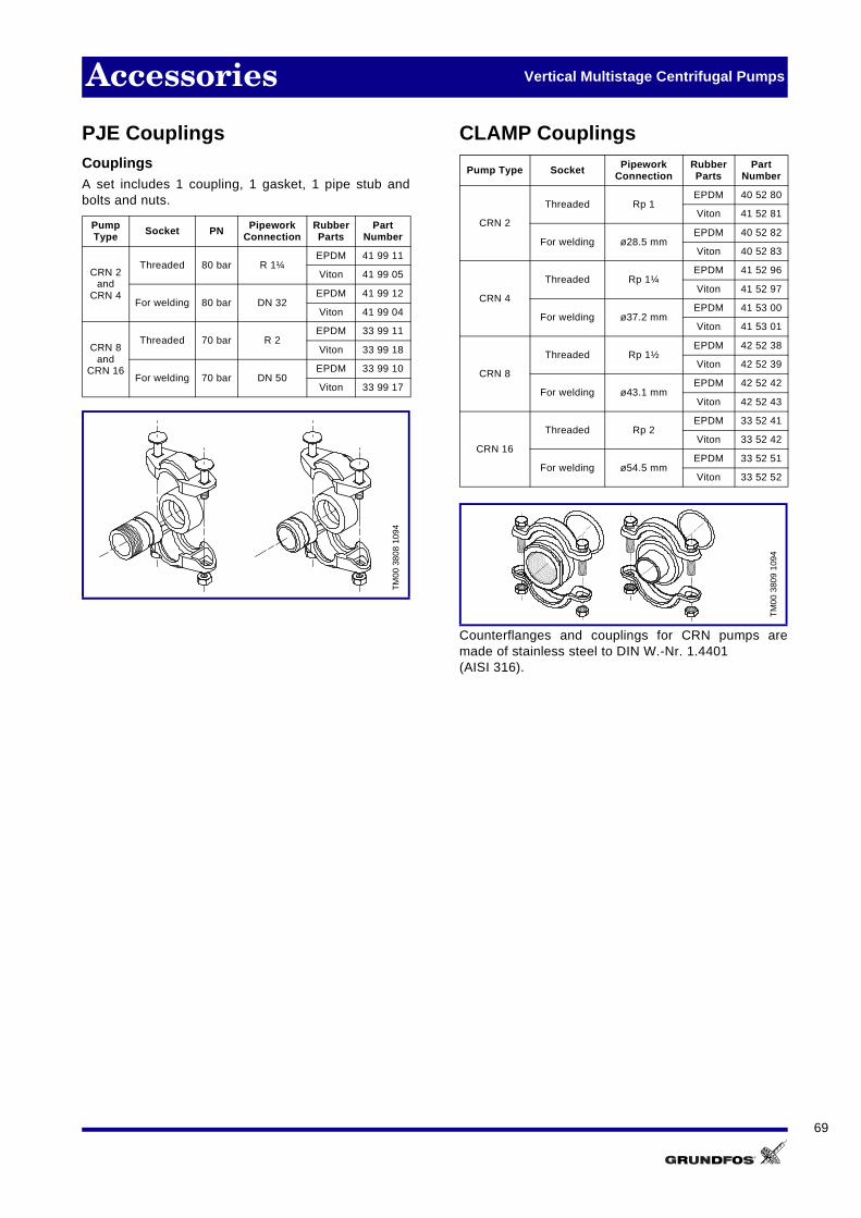
69
Accessories Vertical Multistage Centrifugal Pumps
PJE CouplingsCouplingsA set includes 1 coupling, 1 gasket, 1 pipe stub andbolts and nuts.
CLAMP Couplings
Counterflanges and couplings for CRN pumps aremade of stainless steel to DIN W.-Nr. 1.4401(AISI 316).
PumpType Socket PN Pipework
ConnectionRubberParts
PartNumber
CRN 2and
CRN 4
Threaded 80 bar R 1¼EPDM 41 99 11
Viton 41 99 05
For welding 80 bar DN 32EPDM 41 99 12
Viton 41 99 04
CRN 8and
CRN 16
Threaded 70 bar R 2EPDM 33 99 11
Viton 33 99 18
For welding 70 bar DN 50EPDM 33 99 10
Viton 33 99 17T
M00
380
8 10
94
Pump Type Socket PipeworkConnection
RubberParts
PartNumber
CRN 2
Threaded Rp 1EPDM 40 52 80
Viton 41 52 81
For welding ø28.5 mmEPDM 40 52 82
Viton 40 52 83
CRN 4
Threaded Rp 1¼EPDM 41 52 96
Viton 41 52 97
For welding ø37.2 mmEPDM 41 53 00
Viton 41 53 01
CRN 8
Threaded Rp 1½EPDM 42 52 38
Viton 42 52 39
For welding ø43.1 mmEPDM 42 52 42
Viton 42 52 43
CRN 16
Threaded Rp 2EPDM 33 52 41
Viton 33 52 42
For welding ø54.5 mmEPDM 33 52 51
Viton 33 52 52
TM
00 3
809
1094
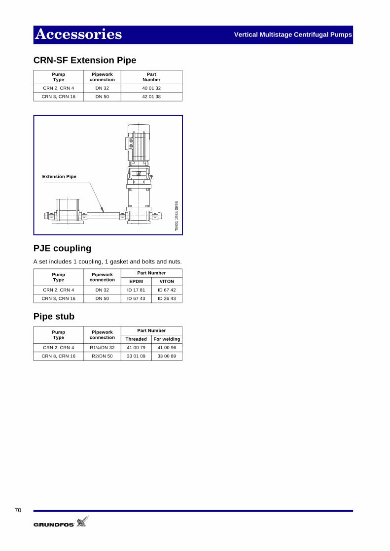
70
Accessories Vertical Multistage Centrifugal Pumps
CRN-SF Extension Pipe
PJE couplingA set includes 1 coupling, 1 gasket and bolts and nuts.
Pipe stub
PumpType
Pipeworkconnection
PartNumber
CRN 2, CRN 4 DN 32 40 01 32
CRN 8, CRN 16 DN 50 42 01 38
TM
01 1
984
0898
PumpType
Pipeworkconnection
Part Number
EPDM VITON
CRN 2, CRN 4 DN 32 ID 17 81 ID 67 42
CRN 8, CRN 16 DN 50 ID 67 43 ID 26 43
PumpType
Pipeworkconnection
Part Number
Threaded For welding
CRN 2, CRN 4 R1¼/DN 32 41 00 79 41 00 96
CRN 8, CRN 16 R2/DN 50 33 01 09 33 00 89
Extension Pipe

71

72

GRUNDFOS A/S . DK-8850 Bjerringbro . DenmarkTelephone: +45 86 68 14 00 . Internet: www.grundfos.com
V7 02 37 51 11 98GBRepl. V7 02 37 51 09 98 Subject to alterations.


