Embed Size (px)
Citation preview
GRUNDFOS PRODUCT GUIDE
DMX
Dosing pumps

2
Contents
Features and benefitsDMX 3
Performance rangeDMX, 1.3 to 166 GPH 4
IdentificationType key 5
FunctionsFunctional overview 6Capacity control 6Functional description, DMX B 7Functional description, DMX AR 7DMX AR 8Control panel 8Connectors 8
ConstructionGeneral description 14DMX model 221 14DMX model 226 15
Technical dataDimensions, DMX model 221 16Dimensions, DMX model 226 17Performance data, DMX model 221 18Performance data, DMX model 226 19Suction lift, DMX model 221 20Suction lift, DMX model 226 21Weights, DMX model 221 22Weights, DMX model 226 22Sound pressure 23Accuracy 23Permissible temperatures of dosing liquid 23
Pump selectionDMX selection (1.3 to 2 x 166 GPH) 24
Pumped liquidsList of pumped liquids 26

DMX
3
Features and benefits
DMXReliable diaphragm dosingfrom 1.3 to 2 x 166 GPH.
DMX 221 and 226 - versatility through choiceThe Grundfos DMX is a series of high-quality mechani-cally actuated diaphragm pumps suitable for many uses, such as drinking water treatment, wastewater treatment, and the pulp/paper and textile industries. This series is designed to be highly versatile, which is reflected in the wide flow range covered and the choice of dosing head sizes, materials, and accessories avail-able. If in doubt, ask us – we will help you configure the DMX that is best for you.
Manual or remote reliable controlDMX B models feature manual stroke length adjust-ment for a 10:1 turndown ratio. For additional control the DMX AR features a micro-processor controller with:
• precise and automatic proportional feed• manual stroke-frequency control• 0(4)-20 mA or pulse control• menu-driven display with user-friendly interface• low-level and empty output• remote on/off control.
Choose the materials – and size – that suit youBoth the DMX 221 and 226 liquid ends are available in PVC, PVDF, polypropylene, and stainless steel. For additional output and flexibility, the DMX 226 is avail-able in a duplex version.
Accessories ensure perfect system integrationA wide range of accessories specially designed for the Grundfos DMX series help optimize performance. This makes commissioning fast and easy. Other accesso-ries are also available to make sure that your Grundfos DMX fits your system exactly, such as:
• back-pressure valves for dosing systems with no or varying back pressure
• servomotor for remote stroke-length control via 4-20 mA input
• DMX AR dosing controller with output to indicate a loss
• DMX AR with leak detection• DMX with integrated pressure relief valve in the
pump head.TM
03 2
134
3705
Fig. 1 DMX

DMX
4
Performance range
DMX, 1.3 to 166 GPH
TM03
477
6 27
06
Fig. 2 Performance range, DMX, 1.3 to 166 GPH
2 5 1010 20 42 61 102 166 200Q [US GPH]
44
87
116
145
232
[psi]p
DMX60 Hz
0
0

DMX
5
Identification
Type keyExample: DMX 115 - 3 B PVC /V /G -X -H 1 A7A7 B
Type range Motor variant
DMX E0 PTC motor for frequency control
Maximum flow [l/h] E1 Motor type EEx de C T3, 3 x 400 V, 50 Hz (only DMX-B or DMX-AT)
Maximum pressure [bar] E2 Motor type EEx de C T4, 3 x 400 V, 50 Hz (only DMX-B or DMX-AT)
Control variant Mains plug
B Standard - manual control X No plugAR Analog/pulse control (Etron Profi) F EU (Schuko)AT0 Prepared for servomotor B USA, Canada
AT3 Servomotor, 1 x 230 V, 50/60 Hz supply, 4-20 mA control
I Australia, New Zealand, TaiwanE Switzerland
AT5 Servomotor, 1 x 115 V, 50/60 Hz supply,4-20 mA control Connection, suction/discharge
AT6 Servomotor, 1 x 230 V, 50/60 Hz supply,4-20 mA control, EEx d II BT 4
4 Tube 6/9 mm6 Tube 9/12 mm
AT7 Servomotor, 1 x 115 V, 50/60 Hz supply,4-20 mA control, EEx d II BT 4
B9 Tube 19/27 mm, PVCQ Tube 19/27 mm and 25/34 mm
AT8 Servomotor, 1x230V 50/60Hz supply, 1KΩ potentiometer control
S Tube 3/8" / 1/2”A Threaded Rp 1/4"
AT9 Servomotor, 1x115V 50/60Hz supply, 1KΩ potentiometer control
A1 Threaded Rp 3/4"A2 Threaded Rp 1 1/4"
Dosing head variantV Threaded NPT 1/4"A9 Threaded NPT 1/2", male
PP Polypropylene A3 Threaded NPT 3/4"PV PVDF (polyvinylidene fluoride) A7 Threaded NPT 3/4", malePVC Polyvinyl chloride A4 Threaded NPT 1 1/4" SS Stainless steel, 316 A8 Threaded NPT 1 1/4", malePV-R PVDF + integrated relief valve K Cementing d. 40 mmPVC-R PVC + integrated relief valve B1 Tube 6/12 mm/cementing d. 12 mmPP-L PP + integrated diaphragm leakage detection B2 Tube 13/20 mm/cementing d. 25 mmPV-L PVDF + integrated diaphragm leakage detection B3 Welding d. 16 mmPVC-L PVC + integrated diaphragm leakage detection B4 Welding d. 25 mmSS-L SS + integrated diaphragm leakage detection B5 Welding d. 40 mm
PV-RL PVDF + integrated relief valve anddiaphragm leakage detection Valve type
PVC-RL PVC + integrated relief valve anddiaphragm leakage detection
1 Standard
2Spring-loaded1.45 psi inlet opening pressure1.45 psi discharge opening pressureGasket material
3Spring-loaded, 0.7 psi inlet opening pressure11.6 psi discharge opening pressureE EPDM (ethylene propylene diene monomer)
V FKM (fluorocarbon) 4 Spring-loaded, discharge side onlyT PTFE (polytetrafluoroethylene, e.g. Teflon®) 5 Valve for abrasive liquids
Valve ball material Supply voltage
C Ceramic 0 Without motor, IEC flangeG Glass G 1 x 230 V, 50/60 HzT PTFE (polytetrafluoroethylene, e.g. Teflon®) H 1 x 120 V, 50/60 HzSS Stainless steel, 316
E 230/400 V, 50/60 Hz or 440/480 V, 60 Hz
Control panel position
F
Without motor, NEMA flange (US)Nema 42C for DMX 221Nema 56C for DMX 226
X No control panel
S Side-mounted
W Wall-mounted J 220-240 V / 380-420 V, 50/60Hz5 3 x 230/460 V, 60 Hz

6
DMXFunctions
Functional overview
Fig. 3 DMX B
Fig. 4 DMX AR
Capacity control
Fig. 5 The capacity is controlled by adjusting the stroke length
Fig. 6 Relation between stroke length and capacity
DMX B DMX ARCapacity controlStroke-frequency controlStroke-length adjustments
Control panelRed light for stopped pump and error signalsGreen light when pump is runningControl-panel lock[Start/Stop] buttonFront-mounted interfaceWall-mounted interface
Operating modesManual controlPulse controlAnalog 0/4-20 mA controlPulse-based batch control
Functions/optionsAlarm outputsDosing controller outputLeak detection (optional diaphragm breakage indication)Dual-level control (requires level controller, available on select sizes) Pulse memory (saves up to 65,000 pulses)Operating-hours counterRemote on/off0/4-20 mA outputAvailable in duplex versions (Check sizing chart for availability)
TM03
213
4 37
05TM
03 6
124
4306
TM03
202
3 35
05TM
03 2
097
3705
l [%]
[l/h]Q
Functions DMX
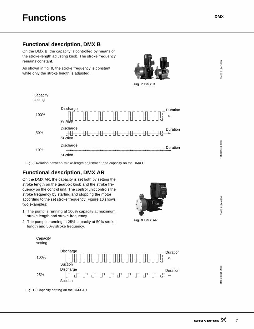
Functional description, DMX BOn the DMX B, the capacity is controlled by means of the stroke-length adjusting knob. The stroke frequency remains constant.
As shown in fig. 8, the stroke frequency is constant while only the stroke length is adjusted.
Fig. 7 DMX B
Fig. 8 Relation between stroke-length adjustment and capacity on the DMX B
Functional description, DMX AROn the DMX AR, the capacity is set both by setting the stroke length on the gearbox knob and the stroke fre-quency on the control unit. The control unit controls the stroke frequency by starting and stopping the motor according to the set stroke frequency. Figure 10 shows two examples:
1. The pump is running at 100% capacity at maximum stroke length and stroke frequency.
2. The pump is running at 25% capacity at 50% stroke length and 50% stroke frequency.
Fig. 9 DMX AR
Fig. 10 Capacity setting on the DMX AR
TM03
213
4 37
05TM
03 2
074
3505
Discharge
Suction
Duration
Discharge
Suction
Duration
Discharge
Suction
Duration
Capacity setting
100%
50%
10%
TM03
612
4 43
06TM
01 8
964
0900
Discharge
Suction
Duration
Discharge
Suction
Duration
100%
25%
Capacity setting
7

Functions DMX
8
DMX AR
Control panel
Fig. 11 Control panel
Legend
Connectors
Fig. 12 Connectors
Legend
Start/stop of pumpStart and stop the pump by means of the [Start/Stop] button. When the pump is stopped, the display shows "stop". If the pump is stopped via an external start/stop signal, the indicator light is permanently yellow.
Operating modesTo select the operating mode, press the [Menu] button. The display indicates the operating mode. To change the mode, use the [Up/Down] buttons, see fig. 11, pos. 4.
Manual controlThe pump is dosing constantly according to the set stroke length. Thanks to its control panel, DMX AR also offers setting of the stroke frequency.
Pulse controlPulse control applies to DMX AR.
The pump is dosing according to an external pulse sig-nal such as a water meter.
The number of pump strokes per pulse (multiplication) can be set between 1:1 and 1:999 and the number of pulses per stroke (division) between 999:1 and 1:1.
Tank-level controlThe tank-level control function applies to DMX AR.
The pump can be fitted with a level-control unit for mon-itoring the chemical level in the tank. The pump can react to two level signals. The following table shows the pump reactions to the sensor signals.
TM03
445
5 21
06
Pos. Component
1
Mode (light-emitting diode):• Red light indicates that the pump has stopped.• Green light indicates that the pump has started; the light is
briefly off during a suction stroke.• Yellow light indicates that the pump is switched off re-
motely.• Red light is flashing in case of an error signal.• Light is off when the pump is in menu mode.
2 Start/Stop (button):• For starting and stopping the pump.
3 Menu (button):• For switching between operating modes.
4 Up/Down (buttons):• For changing the values in the display.
5 LCD display
TM03
722
6 46
06
Socket Description1 Leakage detection2 Current output (indicates the current dosing flow)
3 Output for stroke/pulse signal or empty-tank pre-alert signal and error signal
4Remote on/off Contact inputCurrent input
5 Empty-tank signalEmpty-tank pre-alert and empty-tank signal
Level sensors Pump reaction
Pre-empty sensor activated
• Red indicator light is on.• Empty signature in display is flashing.• Pump running.• Alarm relay activated.
Empty sensor activated
• Red indicator light is on.• Empty signature in display is on.• Pump stopped.• Alarm relay activated.

Functions DMX
Maximum permissible stroke frequencyThe maximum permissible stroke-frequency function applies to DMX-AR.
The maximum stroke frequency of the pump can be lim-ited, for instance to adapt pump operation to an analog 0/4-20 mA signal without reducing the stroke length.
AlarmsThe pump allows to control the metering process. An alarm is indicated visually in the display and forwarded by the alarm relay.
Tank pre-empty alarm signallingThe indicator light flashes, and the pre-empty relay is activated.
Empty-level main alarmThe indicator light is on, and the alarm relay is acti-vated. The pump stops.
Alarm relayThe alarm relay can be set to NO or NC.
Functions of indicator lights and alarm output
* Requires connection to level sensors.
It is possible to programme one relay to pre-empty and another to empty signal.
Diaphragm Breakage Signal and dosing controller
Socket 1Socket 1 can be used for the Diaphragm Breakage Sig-nal (MBS) and/or the dosing controller (DC). The Dia-phragm Breakage Signal and the dosing controller are delivered pre-assembled with an M12 plug for socket 1.
When simultaneously using the diaphragm breakage indication and the dosing controller, both cables must be connected with one plug.
Current output and remote on/offCaution: The current output is not designed for control-ling secondary pumps in master/slave operation.
Socket 2Socket 2 can be used for the remote switching input and current output.
The current output indicates the current dosing flow and can be weighted independently of the selected operat-ing mode.
Stroke signal, pre-empty signal, and error signalNote: Use the stroke signal to control secondary pumps.
Socket 3Socket 3 can be used for electrically isolated output for stroke signal or pre-empty signal and error signal.
Condition Indicator lightPump running Light flashes greenSet to stop Light is permanently redPump fault Light flashes redSupply failure Light is offPump running, low chemical level* Light flashes red/green
Empty tank * Light is permanently redAnalog signal < 2 mA Light flashes red
Pin Assignment
Wire coloursDiaphragm Breakage
SignalDosing
controllerCable, 0.8 metre
Cable, 3 metres
(without plug)1 +12V Brown2 MBS/GND White White3 MBS supply Blue Blue
4 Dosing controller output Blue
5 MBS output Green/yel-low Green
Pin AssignmentCable Used forWire
colour+/- current
outputremote
switching1 +5 V Brown +2 Remote switching input White X3 GND Blue X4 Current output Black -
Pin Assignment
Cable Used for
Wire colour
stroke signal/pre-empty
signalremote
switching
1 Error signal contact Brown X
2 Stroke signal or pre-empty signal contact White X
3 Stroke signal or pre-empty signal contact Blue X
4 Error signal contact Black X
9

Functions DMX
10
Remote on/off, contact input and current inputCaution: The current input is not designed for control-ling a preceding pump in master/slave operation. Instead, use the contact input that controls socket 3.
Socket 4Socket 4 can be used for the remote switching input and contact input or current input. In the event of the simultaneous connection of the remote switching and contact input, wire 1 is assigned twice.
Caution: For the connection of one cable, use a plug adapter with simple cable entry; for the connection of two cables, use a plug adapter with double cable entry. Otherwise, the protection will be lost!
Empty signal, pre-empty and empty signals
Socket 5Socket 5 can be used for the empty signal or pre-empty and empty signal inputs. The suction lines with empty signal or pre-empty and empty signals are delivered pre-assembled with a plug for socket 5.
Menu levelsMenu levels used in the electronics• First function level: This level is used for selecting
and setting the pump operating modes (manual, contact and analog) and starting.
• Second function level: This level is used for setting and viewing additional functions and setting the ac-cess code to protect the pump against unintentional adjustment.
• Service level: This level is used for setting the in-puts and outputs, modifying the version of the Etron Profi Electronics. It is possible to revert to the de-fault settings.
Saving user settingsThe pump settings are automatically saved approxi-mately every 10 minutes. The settings remain after the power supply has been switched off.
General functions of the electronicsDeaeration and suctionIf the [Start/Stop] button is pressed for more than one second, the pump switches to continuous operation. The pump remains in continuous operation as long as the button is pressed (for example for suction or deaer-ation).
This occurs regardless of the selected operating mode.
Locking ‘run’The pump can be locked to avoid manual stopping.
When activating the locking run function (service level), the pump starts running with the present settings and cannot be stopped by means of the [Start/Stop] button.
It is still possible to acknowledge error messages using the [Start/Stop] button.
Pin Assignment
Cable Used for
Wire colour
remote switching
inputcontact
input
+/- current output
1 GND Brown x x -2 Current input White +3 Remote switching Blue x4 Current output Black x
Pin AssignmentUsed for
empty signal pre-empty signal1 Empty signal x2 GND x x3 Pre-empty signal x
Functions DMX
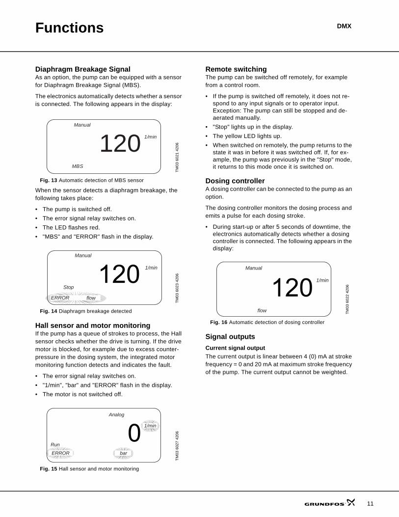
Diaphragm Breakage SignalAs an option, the pump can be equipped with a sensor for Diaphragm Breakage Signal (MBS).
The electronics automatically detects whether a sensor is connected. The following appears in the display:
Fig. 13 Automatic detection of MBS sensor
When the sensor detects a diaphragm breakage, the following takes place:
• The pump is switched off.• The error signal relay switches on.• The LED flashes red.• "MBS" and "ERROR" flash in the display.
Fig. 14 Diaphragm breakage detected
Hall sensor and motor monitoringIf the pump has a queue of strokes to process, the Hall sensor checks whether the drive is turning. If the drive motor is blocked, for example due to excess counter-pressure in the dosing system, the integrated motor monitoring function detects and indicates the fault.
• The error signal relay switches on.• "1/min", "bar" and "ERROR" flash in the display.• The motor is not switched off.
Fig. 15 Hall sensor and motor monitoring
Remote switchingThe pump can be switched off remotely, for example from a control room.
• If the pump is switched off remotely, it does not re-spond to any input signals or to operator input. Exception: The pump can still be stopped and de-aerated manually.
• "Stop" lights up in the display.• The yellow LED lights up.• When switched on remotely, the pump returns to the
state it was in before it was switched off. If, for ex-ample, the pump was previously in the "Stop" mode, it returns to this mode once it is switched on.
Dosing controllerA dosing controller can be connected to the pump as an option.
The dosing controller monitors the dosing process and emits a pulse for each dosing stroke.
• During start-up or after 5 seconds of downtime, the electronics automatically detects whether a dosing controller is connected. The following appears in the display:
Fig. 16 Automatic detection of dosing controller
Signal outputsCurrent signal outputThe current output is linear between 4 (0) mA at stroke frequency = 0 and 20 mA at maximum stroke frequency of the pump. The current output cannot be weighted.
TM03
602
1 42
06TM
03 6
023
4206
TM03
602
7 42
06
Manual
1/min120MBS
Manual
1/min
Stop
ERROR flow
Analog
Run
ERROR
1/min
bar
TM03
602
2 42
06
Manual
1/min
flow
11
Functions DMX
12
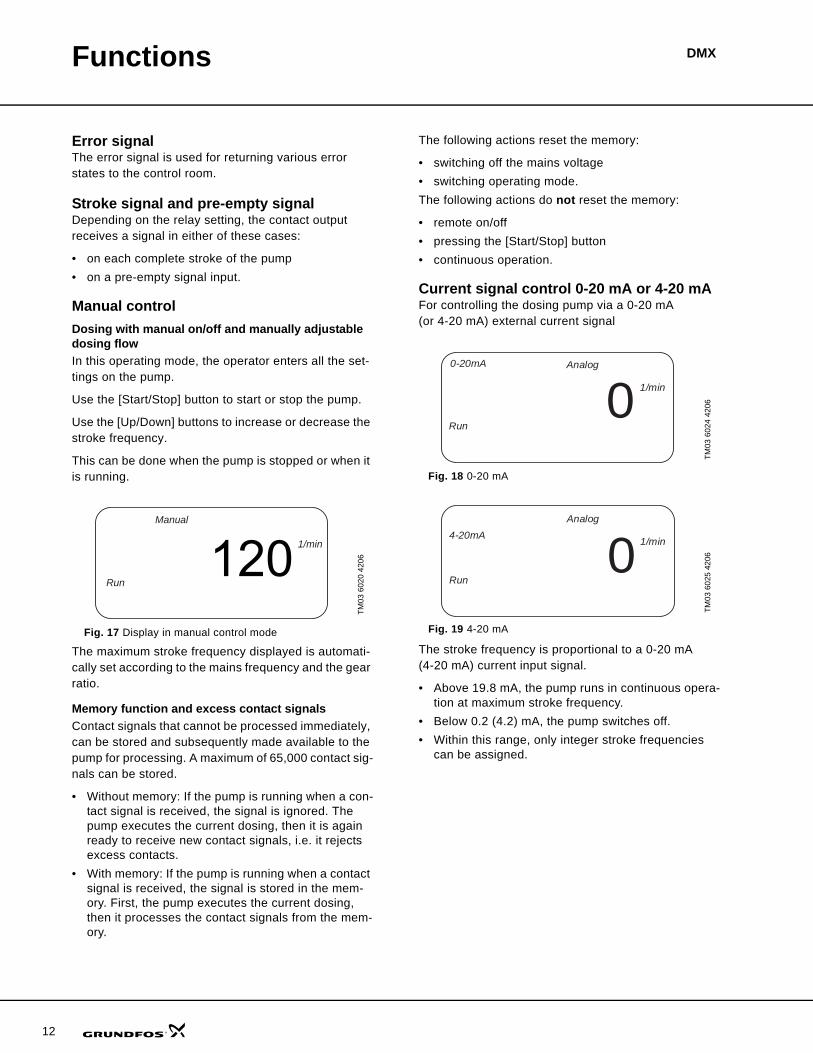
Error signalThe error signal is used for returning various error states to the control room.
Stroke signal and pre-empty signalDepending on the relay setting, the contact output receives a signal in either of these cases:
• on each complete stroke of the pump• on a pre-empty signal input.
Manual controlDosing with manual on/off and manually adjustable dosing flowIn this operating mode, the operator enters all the set-tings on the pump.
Use the [Start/Stop] button to start or stop the pump.
Use the [Up/Down] buttons to increase or decrease the stroke frequency.
This can be done when the pump is stopped or when it is running.
The maximum stroke frequency displayed is automati-cally set according to the mains frequency and the gear ratio.
Memory function and excess contact signalsContact signals that cannot be processed immediately, can be stored and subsequently made available to the pump for processing. A maximum of 65,000 contact sig-nals can be stored.
• Without memory: If the pump is running when a con-tact signal is received, the signal is ignored. The pump executes the current dosing, then it is again ready to receive new contact signals, i.e. it rejects excess contacts.
• With memory: If the pump is running when a contact signal is received, the signal is stored in the mem-ory. First, the pump executes the current dosing, then it processes the contact signals from the mem-ory.
The following actions reset the memory:
• switching off the mains voltage• switching operating mode.The following actions do not reset the memory:
• remote on/off• pressing the [Start/Stop] button• continuous operation.
Current signal control 0-20 mA or 4-20 mAFor controlling the dosing pump via a 0-20 mA (or 4-20 mA) external current signal
Fig. 18 0-20 mA
Fig. 19 4-20 mA
The stroke frequency is proportional to a 0-20 mA (4-20 mA) current input signal.
• Above 19.8 mA, the pump runs in continuous opera-tion at maximum stroke frequency.
• Below 0.2 (4.2) mA, the pump switches off.• Within this range, only integer stroke frequencies
can be assigned.
TM03
602
0 42
06
Fig. 17 Display in manual control mode
Manual
1/min
Run
TM03
602
4 42
06TM
03 6
025
4206
Analog0-20mA
1/min
Run0
Analog
1/min
Run0
4-20mA
Functions DMX
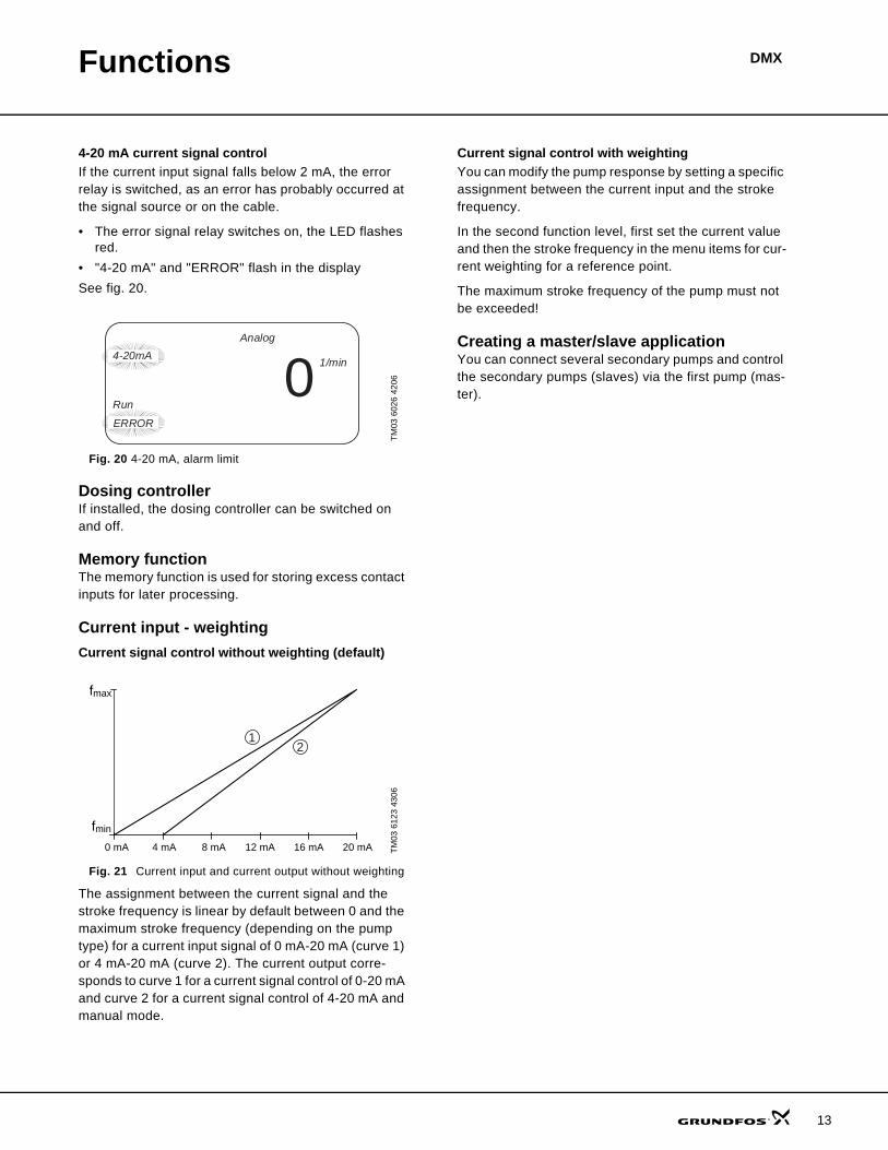
4-20 mA current signal controlIf the current input signal falls below 2 mA, the error relay is switched, as an error has probably occurred at the signal source or on the cable.
• The error signal relay switches on, the LED flashes red.
• "4-20 mA" and "ERROR" flash in the displaySee fig. 20.
Fig. 20 4-20 mA, alarm limit
Dosing controllerIf installed, the dosing controller can be switched on and off.
Memory functionThe memory function is used for storing excess contact inputs for later processing.
Current input - weightingCurrent signal control without weighting (default)
Fig. 21 Current input and current output without weighting
The assignment between the current signal and the stroke frequency is linear by default between 0 and the maximum stroke frequency (depending on the pump type) for a current input signal of 0 mA-20 mA (curve 1) or 4 mA-20 mA (curve 2). The current output corre-sponds to curve 1 for a current signal control of 0-20 mA and curve 2 for a current signal control of 4-20 mA and manual mode.
Current signal control with weightingYou can modify the pump response by setting a specific assignment between the current input and the stroke frequency.
In the second function level, first set the current value and then the stroke frequency in the menu items for cur-rent weighting for a reference point.
The maximum stroke frequency of the pump must not be exceeded!
Creating a master/slave applicationYou can connect several secondary pumps and control the secondary pumps (slaves) via the first pump (mas-ter).
TM03
602
6 42
06TM
03 6
123
4306
Analog
1/min
Run0
ERROR
4-20mA
21
fmax
fmin
0 mA 4 mA 8 mA 12 mA 16 mA 20 mA
13

14
DMXConstruction
General descriptionThe Grundfos DMX pumps are mechanical diaphragm dosing pumps. The strokes are generated by an eccentric which moves the diaphragm by means of a spring-loaded plunger. The discharge stroke is activated by the eccen-tric and the suction stroke by the spring return.
The DMX pumps are designed for capacities between 1.3 and 2 x 166 GPH and a maximum pressure up to 232 psi. The DMX pumps are fitted with a separation chamber. In the event of a diaphragm failure, the separation chamber prevents the pumped liquid from flooding the pump unit or other system components.
DMX model 221
Functional principle• Reciprocating displacement pump with electric mo-
tor and mechanical diaphragm control.• The rotation of the motor is transformed into the re-
ciprocating movement of the dosing diaphragm by the operation of the eccentric and tappet.
• Adjustment of the dosing flow is possible by adjust-ing the stroke length.
Legend:
TM03
218
2 38
05Fig. 22 Sectional drawing, DMX model 221
8
3947
5
6
2
1
Pos. Component1 Motor2 Gears3 Eccentric4 Dosing diaphragm5 Pump head6 Suction valve7 Discharge valve8 Stroke-length adjusting knob9 Tappet
Construction DMX
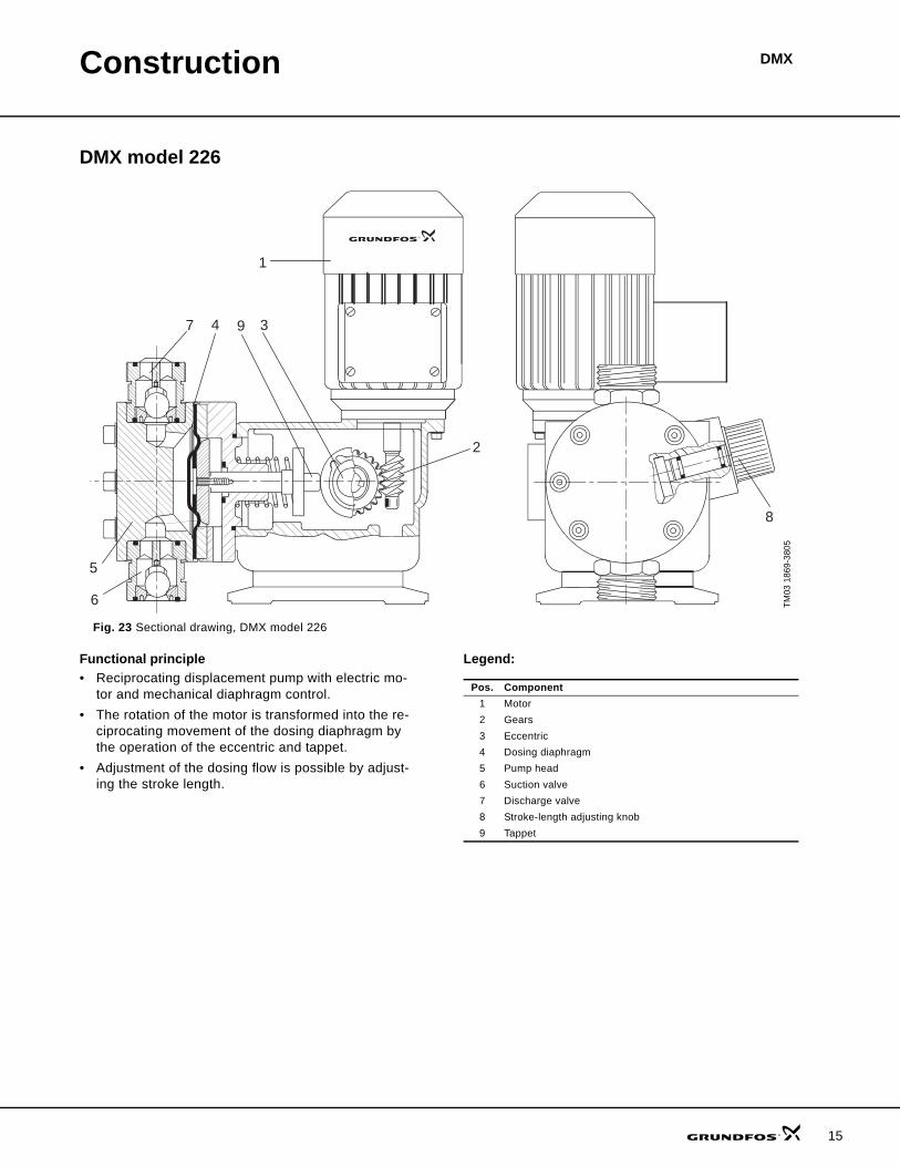
DMX model 226
Functional principle• Reciprocating displacement pump with electric mo-
tor and mechanical diaphragm control.• The rotation of the motor is transformed into the re-
ciprocating movement of the dosing diaphragm by the operation of the eccentric and tappet.
• Adjustment of the dosing flow is possible by adjust-ing the stroke length.
Legend:
TM03
186
9-38
05
Fig. 23 Sectional drawing, DMX model 226
8
3947
5
6
2
1
Pos. Component1 Motor2 Gears3 Eccentric4 Dosing diaphragm5 Pump head6 Suction valve7 Discharge valve8 Stroke-length adjusting knob9 Tappet
15

16
Technical data
Dimensions, DMX model 221
Dimensions in inches (mm)TM
03 1
731
3605
Fig. 24 Dimensions, DMX model 221
Pump Model A B C C1 D D1 D2 E F G I K M N QDMX 4-10 221 10.83
(275)12.56(319)
4.13(105)
0.41(10.5)
6.89(175)
R 5/8 0.26(6.5)
6.02(153)
6.26(159)
4.04(102.5)
0.98(25)
1.26(32)
7.09(180)
4.84(123)
7.05(179)
DMX 7-10 221 10.83(275)
12.56(319)
4.13(105)
0.41(10.5)
6.89(175)
R 5/8 0.26(6.5)
6.02(153)
6.26(159)
4.04(102.5)
0.98(25)
1.26(32)
7.09(180)
4.84(123)
7.05(179)
DMX 7-16 221 10.83(275)
12.56(319)
4.13(105)
0.41(10.5)
6.89(175)
R 5/8 0.26(6.5)
6.02(153)
6.26(159)
4.04(102.5)
0.98(25)
1.26(32)
7.09(180)
4.84(123)
7.05(179)
DMX 8-10 221 10.83(275)
12.56(319)
4.13(105)
0.41(10.5)
6.89(175)
R 5/8 0.26(6.5)
6.02(153)
6.26(159)
4.04(102.5)
0.98(25)
1.26(32)
7.09(180)
4.84(123)
7.05(179)
DMX 9-10 221 10.83(275)
12.56(319)
4.13(105)
0.41(10.5)
6.89(175)
R 5/8 0.26(6.5)
6.02(153)
6.26(159)
4.04(102.5)
0.98(25)
1.26(32)
7.09(180)
4.84(123)
7.05(179)
DMX 12-10 221 10.83(275)
12.56(319)
4.13(105)
0.41(10.5)
6.89(175)
R 5/8 0.26(6.5)
6.02(153)
6.26(159)
4.04(102.5)
0.98(25)
1.26(32)
7.09(180)
4.84(123)
7.05(179)
DMX 14-16 221 10.83(275)
12.56(319)
4.13(105)
0.41(10.5)
6.89(175)
R 5/8 0.26(6.5)
6.02(153)
6.26(159)
4.04(102.5)
0.98(25)
1.26(32)
7.09(180)
4.84(123)
7.05(179)
DMX 14-10 221 10.83(275)
12.56(319)
4.13(105)
0.41(10.5)
6.89(175)
R 5/8 0.26(6.5)
6.02(153)
6.26(159)
4.04(102.5)
0.98(25)
1.26(32)
7.09(180)
4.84(123)
7.05(179)
DMX 16-10 221 10.83(275)
12.56(319)
4.13(105)
0.41(10.5)
6.89(175)
R 5/8 0.26(6.5)
6.02(153)
6.26(159)
4.04(102.5)
0.98(25)
1.26(32)
7.09(180)
4.84(123)
7.05(179)
DMX 17-4 221 12.72(323)
12.56(319)
4.13(105)
0.41(10.5)
6.89(175)
R 1 1/4 0.26(6.5)
6.97(177)
6.26(159)
4.04(102.5)
1.5(38)
2.52(64)
7.09(180)
4.84(123)
7.56(192)
DMX 18-10 221 10.83(275)
12.56(319)
4.13(105)
0.41(10.5)
6.89(175)
R 5/8 0.26(6.5)
6.02(153)
6.26(159)
4.04(102.5)
0.98(25)
1.26(32)
7.09(180)
4.84(123)
7.05(179)
DMX 25-3 221 12.99(330)
12.56(319)
4.13(105)
0.41(10.5)
6.89(175)
R 1 1/4 0.26(6.5)
7.4(188)
6.26(159)
4.04(102.5)
1.57(40)
3.15(80)
7.09(180)
4.84(123)
7.76(197)
DMX 26-10 221 10.83(275)
12.56(319)
4.13(105)
0.41(10.5)
6.89(175)
R 5/8 0.26(6.5)
6.02(153)
6.26(159)
4.04(102.5)
0.98(25)
1.26(32)
7.09(180)
4.84(123)
7.05(179)
DMX 27-10 221 10.83(275)
12.56(319)
4.13(105)
0.41(10.5)
6.89(175)
R 5/8 0.26(6.5)
6.02(153)
6.26(159)
4.04(102.5)
0.98(25)
1.26(32)
7.09(180)
4.84(123)
7.05(179)
DMX 35-10 221 10.83(275)
12.56(319)
4.13(105)
0.41(10.5)
6.89(175)
R 5/8 0.26(6.5)
6.02(153)
6.26(159)
4.04(102.5)
0.98(25)
1.26(32)
7.09(180)
4.84(123)
7.05(179)
DMX 39-4 221 12.72(323)
12.56(319)
4.13(105)
0.41(10.5)
6.89(175)
R 1 1/4 0.26(6.5)
6.97(177)
6.26(159)
4.04(102.5)
1.5(38)
2.52(64)
7.09(180)
4.84(123)
7.56(192)
DMX 50-10 221 10.83(275)
12.56(319)
4.13(105)
0.41(10.5)
6.89(175)
R 5/8 0.26(6.5)
6.02(153)
6.26(159)
4.04(102.5)
0.98(25)
1.26(32)
7.09(180)
4.84(123)
7.05(179)
DMX 60-3 221 12.99(330)
12.56(319)
4.13(105)
0.41(10.5)
6.89(175)
R 1 1/4 0.26(6.5)
7.4(188)
6.26(159)
4.04(102.5)
1.57(40)
3.15(80)
7.09(180)
4.84(123)
7.76(197)
DMX 75-4 221 12.72(323)
12.56(319)
4.13(105)
0.41(10.5)
6.89(175)
R 1 1/4 0.26(6.5)
6.97(177)
6.26(159)
4.04(102.5)
1.5(38)
2.52(64)
7.09(180)
4.84(123)
7.56(192)
DMX 115-3 221 12.99(330)
12.56(319)
4.13(105)
0.41(10.5)
6.89(175)
R 1 1/4 0.26(6.5)
7.4(188)
6.26(159)
4.04(102.5)
1.57(40)
3.15(80)
7.09(180)
4.84(123)
7.76(197)
DMX
Technical data DMX
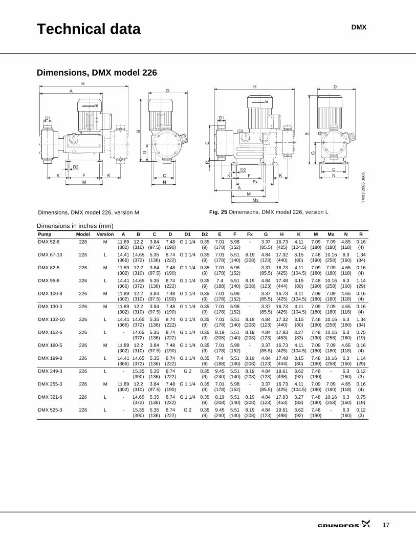
Dimensions, DMX model 226
Dimensions in inches (mm)
TM03
208
6 36
05
Dimensions, DMX model 226, version M Fig. 25 Dimensions, DMX model 226, version L
Pump Model Version A B C D D1 D2 E F Fx G H K M Mx N RDMX 52-8 226 M 11.89
(302)12.2 (310)
3.84 (97.5)
7.48 (190)
G 1 1/4 0.35 (9)
7.01 (178)
5.98 (152)
- 3.37 (85.5)
16.73 (425)
4.11 (104.5)
7.09 (180)
7.09 (180)
4.65 (118)
0.16 (4)
DMX 67-10 226 L 14.41 (366)
14.65 (372)
5.35 (136)
8.74 (222)
G 1 1/4 0.35 (9)
7.01 (178)
5.51 (140)
8.19 (208)
4.84 (123)
17.32 (440)
3.15 (80)
7.48 (190)
10.16 (258)
6.3 (160)
1.34 (34)
DMX 82-5 226 M 11.89 (302)
12.2 (310)
3.84 (97.5)
7.48 (190)
G 1 1/4 0.35 (9)
7.01 (178)
5.98 (152)
- 3.37 (85.5)
16.73 (425)
4.11 (104.5)
7.09 (180)
7.09 (180)
4.65 (118)
0.16 (4)
DMX 95-8 226 L 14.41 (366)
14.65 (372)
5.35 (136)
8.74 (222)
G 1 1/4 0.35 (9)
7.4 (188)
5.51 (140)
8.19 (208)
4.84 (123)
17.48 (444)
3.15 (80)
7.48 (190)
10.16 (258)
6.3 (160)
1.14 (29)
DMX 100-8 226 M 11.89 (302)
12.2 (310)
3.84 (97.5)
7.48 (190)
G 1 1/4 0.35 (9)
7.01 (178)
5.98 (152)
- 3.37 (85.5)
16.73 (425)
4.11 (104.5)
7.09 (180)
7.09 (180)
4.65 (118)
0.16 (4)
DMX 130-3 226 M 11.89 (302)
12.2 (310)
3.84 (97.5)
7.48 (190)
G 1 1/4 0.35 (9)
7.01 (178)
5.98 (152)
- 3.37 (85.5)
16.73 (425)
4.11 (104.5)
7.09 (180)
7.09 (180)
4.65 (118)
0.16 (4)
DMX 132-10 226 L 14.41 (366)
14.65 (372)
5.35 (136)
8.74 (222)
G 1 1/4 0.35 (9)
7.01 (178)
5.51 (140)
8.19 (208)
4.84 (123)
17.32 (440)
3.15 (80)
7.48 (190)
10.16 (258)
6.3 (160)
1.34 (34)
DMX 152-6 226 L - 14.65 (372)
5.35 (136)
8.74 (222)
G 1 1/4 0.35 (9)
8.19 (208)
5.51 (140)
8.19 (208)
4.84 (123)
17.83 (453)
3.27 (83)
7.48 (190)
10.16 (258)
6.3 (160)
0.75 (19)
DMX 160-5 226 M 11.89 (302)
12.2 (310)
3.84 (97.5)
7.48 (190)
G 1 1/4 0.35 (9)
7.01 (178)
5.98 (152)
- 3.37 (85.5)
16.73 (425)
4.11 (104.5)
7.09 (180)
7.09 (180)
4.65 (118)
0.16 (4)
DMX 199-8 226 L 14.41 (366)
14.65 (372)
5.35 (136)
8.74 (222)
G 1 1/4 0.35 (9)
7.4 (188)
5.51 (140)
8.19 (208)
4.84 (123)
17.48 (444)
3.15 (80)
7.48 (190)
10.16 (258)
6.3 (160)
1.14 (29)
DMX 249-3 226 L - 15.35 (390)
5.35 (136)
8.74 (222)
G 2 0.35 (9)
9.45 (240)
5.51 (140)
8.19 (208)
4.84 (123)
19.61 (498)
3.62 (92)
7.48 (190)
- 6.3 (160)
0.12 (3)
DMX 255-3 226 M 11.89 (302)
12.2 (310)
3.84 (97.5)
7.48 (190)
G 1 1/4 0.35 (9)
7.01 (178)
5.98 (152)
- 3.37 (85.5)
16.73 (425)
4.11 (104.5)
7.09 (180)
7.09 (180)
4.65 (118)
0.16 (4)
DMX 321-6 226 L - 14.65 (372)
5.35 (136)
8.74 (222)
G 1 1/4 0.35 (9)
8.19 (208)
5.51 (140)
8.19 (208)
4.84 (123)
17.83 (453)
3.27 (83)
7.48 (190)
10.16 (258)
6.3 (160)
0.75 (19)
DMX 525-3 226 L - 15.35 (390)
5.35 (136)
8.74 (222)
G 2 0.35 (9)
9.45 (240)
5.51 (140)
8.19 (208)
4.84 (123)
19.61 (498)
3.62 (92)
7.48 (190)
- 6.3 (160)
0.12 (3)
17

Technical data
18
DMX
Performance data, DMX model 221
1) The maximum flow is measured at maximum back pressure.2) Maximum back pressure.3) Motor for frequency control.*) Operation at a back pressure of 232 psi reduces diaphragm life.
The values in the table above are based on the follow-ing conditions:
• dosing liquid: water• flooded suction: 1.6 ft.• fully vented dosing head• 400 V motor, 3-phase.
Minimum back pressure: 14.5 psi.
The back pressure refers to the pressure at the pump discharge valve. Pressure losses in the line to the injec-tion point are not taken into account.
Pump ModelVstroke[cm3]
60 Hz Motor power
Capacity 1) [GPH (l/hr)]
Max. pressure 2) [psi (bar)]
Stroke rate[n/min]
Standard[kW]
PTC 3)
[kW] DMX 4-10 221 2.2 1.3 (5) 145 (10) 35 0.09 0.09DMX 7-10 221 3.8 2.1 (8) 145 (10) 35 0.09 0.09DMX 7-16* 221 1.9 2.6 (10) 232 (16) 75 0.09 0.18DMX 8-10 221 2.2 2.6 (10) 145 (10) 75 0.09 0.09DMX 9-10 221 4.9 2.9 (11) 145 (10) 35 0.09 0.09DMX 12-10 221 6.9 3.7 (14) 145 (10) 35 0.09 0.18DMX 14-16* 221 1.9 5.0 (19) 232 (16) 144 0.09 0.18DMX 14-10 221 3.8 4.5 (17) 145 (10) 75 0.09 0.09DMX 16-10 221 2.2 5.0 (19) 145 (10) 144 0.09 -DMX 17-4 221 10.4 5.3 (20) 58 (4) 35 0.09 0.18DMX 18-10 221 4.9 5.8 (22) 145 (10) 75 0.09 0.09DMX 25-3 221 16.0 8.5 (32) 44 (3) 35 0.09 0.18DMX 26-10 221 6.9 8.2 (31) 145 (10) 75 0.09 0.18DMX 27-10 221 3.8 8.5 (32) 145 (10) 144 0.09 -DMX 35-10 221 4.9 11.1 (42) 145 (10) 144 0.09 -DMX 39-4 221 10.4 12.4 (47) 58 (4) 75 0.09 0.18DMX 50-10 221 6.9 15.9 (60) 116 (8) 144 0.09 -DMX 60-3 221 16.0 19.0 (72) 44 (3) 75 0.09 0.18DMX 75-4 221 10.4 23.8 (90) 51 (3.5) 144 0.09 -DMX 115-3 221 16.0 36.5 (138) 36 (2.5) 144 0.09 -

Technical data DMX
Performance data, DMX model 226
1) The maximum flow is measured at maximum back pressure.2) The capacity is per dosing head.
(Twin-head pumps have double the flow rate of single-head versions.)3) Maximum back pressure.4) Motor for frequency control.
The values in the table above are based on the follow-ing conditions:
• maximum back pressure• dosing liquid: water• flooded suction: 1.6 ft.• fully vented dosing head• 400 V, 3-phase motor.
Pump ModelVstroke[cm3]
60 Hz Motor power If delivered without motor
Capacity 1) 2)
[GPH (l/hr)]
Max. pressure 3)
3-phase[psi (bar)]
Max. pressure 3)
1-phase[psi (bar)]
Stroke rate[n/min]
Standard[kW]
PTC 4)
[kW]
Recommended motor power
[hp]
DMX 52-8 226 13.8 16.4 (62) 116 (8) 116 (8) 75.6 0.18 - 0.25
DMX 67-10 226 18.5 21.1 (80) 145 (10) 145 (10) 68.4 0.37 0.55 0.5
DMX 82-5 226 22.0 25.9 (98) 73 (5) 73 (5) 75.6 0.18 - 0.25DMX 95-8 226 27.8 30.1 (114) 116 (8) 116 (8) 68.4 0.37 0.55 0.5
DMX 100-8 226 13.8 31.7 (120) 116 (8) 116 (8) 144 0.18 - 0.25
DMX 130-3 226 36.0 41.2 (156) 44 (3) 44 (3) 75.6 0.18 - 0.25DMX 132-10 226 18.5 41.7 (158) 145 (10) 145 (10) 144 0.37 0.55 0.5
DMX 152-6 226 44.6 48.1 (182) 87 (6) 87 (6) 68.4 0.37 0.55 0.5
DMX 160-5 226 22.0 50.7 (192) 73 (5) 73 (5) 144 0.18 - 0.25DMX 199-8 226 27.8 63.1 (239) 116 (8) 116 (8) 144 0.37 0.55 0.5
DMX 249-3 226 73.0 79.0 (299) 44 (3) 44 (3) 68.4 0.37 0.55 0.5
DMX 255-3 226 36.0 80.8 (306) 44 (3) 44 (3) 144 0.18 - 0.25DMX 321-6 226 44.6 101.7 (385) 87 (6) 58 (4) 144 0.37 0.55 0.5
DMX 525-3 226 73.0 166.4 (630) 44 (3) 44 (3) 144 0.37 0.55 0.5
19
Technical data
20
DMX
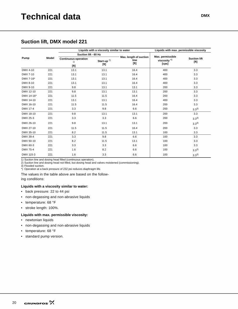
Suction lift, DMX model 221
1) Suction line and dosing head filled (continuous operation).2) Suction line and dosing head not filled, but dosing head and valves moistened (commissioning).3) Flooded suction.*) Operation at a back pressure of 232 psi reduces diaphragm life.
The values in the table above are based on the follow-ing conditions:
Liquids with a viscosity similar to water:• back pressure: 22 to 44 psi• non-degassing and non-abrasive liquids• temperature: 68 °F• stroke length: 100%.
Liquids with max. permissible viscosity:• newtonian liquids• non-degassing and non-abrasive liquids• temperature: 68 °F• standard pump version.
Pump Model
Liquids with a viscosity similar to water Liquids with max. permissible viscositySuctíon lift - 60 Hz
Max. length of suction line[ft]
Max. permissible viscosity 4)
[cps]
Suction lift [ft]
Continuous operation 1)
[ft]Start-up 2)
[ft]
DMX 4-10 221 13.1 13.1 16.4 400 3.3DMX 7-10 221 13.1 13.1 16.4 400 3.3DMX 7-16* 221 13.1 13.1 16.4 400 3.3DMX 8-10 221 13.1 13.1 16.4 400 3.3DMX 9-10 221 9.8 13.1 13.1 200 3.3DMX 12-10 221 9.8 13.1 13.1 200 3.3DMX 14-16* 221 11.5 11.5 16.4 200 3.3DMX 14-10 221 13.1 13.1 16.4 400 3.3DMX 16-10 221 11.5 11.5 16.4 200 3.3DMX 17-4 221 3.3 9.8 6.6 200 3.33)
DMX 18-10 221 9.8 13.1 13.1 200 3.3DMX 25-3 221 3.3 3.3 6.6 200 3.33)
DMX 26-10 221 9.8 13.1 13.1 200 3.33)
DMX 27-10 221 11.5 11.5 16.4 200 3.3DMX 35-10 221 8.2 11.5 13.1 100 3.3DMX 39-4 221 3.3 9.8 6.6 100 3.3DMX 50-10 221 8.2 11.5 13.1 100 3.3DMX 60-3 221 3.3 3.3 6.6 100 3.3DMX 75-4 221 1.6 8.2 6.6 100 3.33)
DMX 115-3 221 1.6 3.3 6.6 100 3.33)

Technical data DMX
Suction lift, DMX model 226
1) Suction line and dosing head filled (continuous operation).2) Suction line and dosing head not filled, but dosing head and valves moistened (commissioning).3) Greater viscosity may be available with special check valve configuration.
The values in the table above are based on the follow-ing conditions:
Liquids with a viscosity similar to water:• back pressure: 22 to 44 psi• non-degassing and non-abrasive liquids• temperature: 68 °F• stroke length: 100%• standard pump version.
Liquids with max. permissible viscosity:• newtonian liquids• non-degassing and non-abrasive liquids• temperature: 68 °F• standard pump version.
Pump Model
Liquids with a viscosity similar to water Liquids with max. permissible viscositySuctíon lift - 60 Hz Max. length of suction
line[ft]
Max. permissible viscosity 3)
[cps]
Suction lift [ft]Continuous operation 1)
[ft]Start-up 2)
[ft]DMX 52-8 226 8.2 3.3 13.1 700 3.3DMX 67-10 226 8.2 3.3 13.1 700 3.3
DMX 82-5 226 8.2 3.3 9.8 500 3.3
DMX 95-8 226 8.2 3.3 9.8 500 3.3DMX 100-8 226 8.2 3.3 13.1 400 3.3
DMX 130-3 226 6.6 3.3 9.8 400 0
DMX 132-10 226 8.2 3.3 13.1 400 3.3DMX 152-6 226 6.6 3.3 9.8 400 0
DMX 160-5 226 8.2 3.3 9.8 200 0
DMX 199-8 226 8.2 3.3 9.8 200 0DMX 249-3 226 3.3 1.6 6.6 100 0
DMX 255-3 226 6.6 3.3 9.8 100 0
DMX 321-6 226 6.6 3.3 9.8 100 0DMX 525-3 226 3.3 1.6 6.6 50 0
21

Technical data
22
DMX
Weights, DMX model 221
The weights are approximate.
Weights, DMX model 226
The weights are approximate.
PumpWeights
[lbs]PVC, PP, PVDF Stainless steel
DMX 4-10 11 15.4DMX 7-10 11 15.4DMX 7-16 11 15.4DMX 8-10 11 15.4DMX 9-10 11 15.4DMX 12-10 11 15.4DMX 14-16 11 15.4DMX 14-10 11 15.4DMX 16-10 11 15.4DMX 17-4 16.5 26.5DMX 18-10 11 15.4DMX 25-3 17.6 28.7DMX 26-10 11 15.4DMX 27-10 11 15.4DMX 35-10 11 15.4DMX 39-4 16.5 26.5DMX 50-10 11 15.4DMX 60-3 17.6 28.7DMX 75-4 16.5 26.5DMX 115-3 17.6 28.7
Pump
Weights [lbs]
Simplex pump Duplex pumpPVC, PP,
PVDFStainless
steelPVC, PP,
PVDFStainless
steelDMX 52-8 33 46 53 79DMX 67-10 46 66 66 106DMX 82-5 33 46 53 79DMX 95-8 46 66 66 106DMX 100-8 33 46 53 79DMX 130-3 33 46 53 79DMX 132-10 46 66 66 106DMX 152-6 46 66 66 106DMX 160-5 33 46 53 79DMX 199-8 46 66 66 106DMX 249-3 46 66 66 106DMX 255-3 33 46 53 79DMX 321-6 46 66 66 106DMX 525-3 46 66 66 106
Technical data DMX
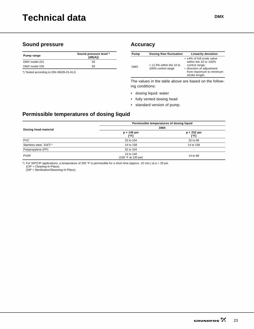
Sound pressure
*) Tested according to DIN 45635-01-KL3.
Accuracy
The values in the table above are based on the follow-ing conditions:
• dosing liquid: water• fully vented dosing head• standard version of pump.
Permissible temperatures of dosing liquid
*) For SIP/CIP applications, a temperature of 293 °F is permissible for a short time (approx. 15 min.) at p < 29 psi.(CIP = Cleaning-In-Place).(SIP = Sterilisation/Steaming-In-Place).
Pump range Sound pressure level *[dB(A)]
DMX model 221 55DMX model 226 55
Pump Dosing flow fluctuation Linearity deviation
DMX < ±1.5% within the 10 to 100% control range
• ±4% of full-scale value within the 20 to 100% control range;
• direction of adjustment from maximum to minimum stroke length.
Dosing head material
Permissible temperatures of dosing liquidDMX
p < 145 psi[°F]
p < 232 psi[°F]
PVC 32 to 104 32 to 68Stainless steel, 316Ti * 14 to 158 14 to 158Polypropylene (PP) 32 to 104 -
PVDF 14 to 140(158 °F at 130 psi) 14 to 68
23

24
DMXPump selection
DMX selection (1.3 to 2 x 166 GPH)The example in bold is a: DMX 4-10 B PV/T/T-X-H1SSB
Max. capacity and pressure
Control variant Materials of dosing head, gaskets and valve balls
Control panel position
Motor voltage
Valve type
Connection, suction/discharge Mains plug
[l/h] - [bar]
B = No controls
AR = Etron Profi (analog/pulse control)
AT5= Servomotor1 x 115 V, 50/60 Hz, 4-20 mA
Dosing head version:PP = PolypropylenePV = PVDF PVC=Polyvinyl chloride SS = Stainless steel 316
PV-R, PVC-R = Integrated relief valve
PP-L, PV-L. PVC-L, SS-L = Integrated diaphragm
leakage detectionPV-RL, PVC-RL
= Integrated relief valve anddiaphragm leakage detection
Gasket material:E = EPDMV = FKM (fluorocarbon)T = PTFE
Valve ball material:C = CeramicG = GlassT = PTFE SS = Stainless steel 316
Control panel positionX = No panelS = Side-mountedW = Wall-mounted
Motor voltageH = 1 x 120 V, 50/60 HzF = Without motor,
Nema flange,(US) Nema 42C for DMX 221Nema 56C for DMX 226
Valve type1 = Standard3 = Spring-loaded,
0.7 psi suction,11.6 psi discharge
4 = Spring-loaded, discharge side only
5 = Valves for abrasive liquids
S = Tube 0.375" / 0.5”V = Threaded NPT 1/4"A9 = Threaded NPT 1/2"
maleA3 = Threaded NPT 3/4"A7 = Threaded NPT 3/4"
maleA4 = Threaded NPT 1 1/4"A8 = Threaded NPT 1 1/4"
male
B = USA andCAN, 120 V
X = No plug
Size Control variant Materials of dosing head, gaskets and valve balls
Control panel position
Motor voltage
Valve type
Connection,suction / discharge Mains plug
DMX 221, DN8
4-107-107-168-109-1012-1014-1614-1016-1018-1026-1027-1035-1050-10
BARAT5
PP/E/CPP/E/SSPP/E/TPP/V/CPP/V/GPP/V/TPV/T/CPV/T/TPV/V/TPVC/E/CPVC/E/SSPVC/E/TPVC/T/CPVC/T/TPVC/V/CPVC/V/GPVC/V/SS
XSW
H1345
S (PVC, PP)A9 (PVDF is
optional on PVCdosing heads)
BX
SS/T/SSSS/V/SS
XSW
H134
A9V
BX
DMX 221, DN20
17-425-339-460-375-4115-3
BARAT5
PP/E/SSPP/E/TPP/T/TPP/V/GPTFE/T/CPV/T/TPVC/E/SSPVC/E/TPVC/T/CPVC/V/CPVC/V/GPVC/V/SS
XSW
H134
A7 (PVDF, PVC) BX
SS/T/SSSS/V/SS
XSW
H134
A3 BX
DMX 226, DN20

Pump selection DMX
52-867-1082-595-8100-8130-3132-10152-6160-5199-8255-3321-6
BARAT5
PP/E/SSPP/E/TPP/T/TPP/V/GPV/T/TPV/V/TPVC/E/SSPVC/E/TPVC/T/CPVC/V/CPVC/V/GPVC/V/SS
XSW
HF
134
A7 (PVDF, PVC) BX
SS/T/SSSS/V/SS
XSW
HF
134
A3 BX
DMX 226, DN32
249-3525-3
BARAT5
PP/E/TPP/V/GPV/T/TPVC/E/SSPVC/V/G
XSW
HF
134
A8 (PVDF, PVC) BX
SS/E/SSSS/T/SSSS/V/SS
XSW
HF
134
A4 BX
Note:Mains plug only for single-phase pumps.DMX model 226 is available with two dosing heads.Type key example: DMX 160-5/160-5 B PP/V/G-X-F1A7A7X.
Max. capacity and pressure
Control variant Materials of dosing head, gaskets and valve balls
Control panel position
Motor voltage
Valve type
Connection, suction/discharge Mains plug
[l/h] - [bar]
B = No controls
AR = Etron Profi (analog/pulse control)
AT5= Servomotor1 x 115 V, 50/60 Hz, 4-20 mA
Dosing head version:PP = PolypropylenePV = PVDF PVC=Polyvinyl chloride SS = Stainless steel 316
PV-R, PVC-R = Integrated relief valve
PP-L, PV-L. PVC-L, SS-L = Integrated diaphragm
leakage detectionPV-RL, PVC-RL
= Integrated relief valve anddiaphragm leakage detection
Gasket material:E = EPDMV = FKM (fluorocarbon)T = PTFE
Valve ball material:C = CeramicG = GlassT = PTFE SS = Stainless steel 316
Control panel positionX = No panelS = Side-mountedW = Wall-mounted
Motor voltageH = 1 x 120 V, 50/60 HzF = Without motor,
Nema flange,(US) Nema 42C for DMX 221Nema 56C for DMX 226
Valve type1 = Standard3 = Spring-loaded,
0.7 psi suction,11.6 psi discharge
4 = Spring-loaded, discharge side only
5 = Valves for abrasive liquids
S = Tube 0.375" / 0.5”V = Threaded NPT 1/4"A9 = Threaded NPT 1/2"
maleA3 = Threaded NPT 3/4"A7 = Threaded NPT 3/4"
maleA4 = Threaded NPT 1 1/4"A8 = Threaded NPT 1 1/4"
male
B = USA andCAN, 120 V
X = No plug
Size Control variant Materials of dosing head, gaskets and valve balls
Control panel position
Motor voltage
Valve type
Connection,suction / discharge Mains plug
25

DMX
26
Pumped liquids
List of pumped liquidsThis resistance table is intended to serve as a general guide only for material resistance (at room tempera-ture) and is not a substitute for actual testing of the chemicals and pump materials under specific working conditions.
The data shown is based upon information from various sources available, but be aware that many factors, such as purity, temperature, abrasive particles, etc. can affect the chemical resistance of a given material.
Note: Some of the liquids in this table may be toxic, cor-rosive or hazardous.
Note: Be careful when handling these liquids.
Pumped liquid (68°F)
Con
cent
ratio
n%
MaterialsPump housing Gasket Ball
Designation Chemical formula
PP PVD
F
Stai
nles
s st
eel,
316
PVC
FKM
EPD
M
PTFE
Cen
telle
n C
Cer
amic
Gla
ss
Acetic acid CH3COOH25 –60 –85 – – –
Aluminium chloride AlCl3 40 –Aluminium sulphate Al2(SO4)3 60 –Ammonia, aqueous NH4OH 28 – –Calcium hydroxide 5 Ca(OH)2Calcium hypochlorite Ca(OCl)2 20 –
Chromic acid 3 H2CrO4
1030 – –40 – – –50 – – –
Copper sulphate CuSO4 30Ferric chloride 1 FeCl3 100 –Ferric sulphate 1 Fe2(SO4)3 100Ferrous chloride FeCl2 100 –Ferrous sulphate FeSO4 50
Hydrochloric acid HCl<25 –
25 to 37 – –Hydrogen peroxide H2O2 30
Nitric acid HNO3
1030 –40 –70 – – – –
Peracetic acid CH3COOOH 5 – –Potassium hydroxide KOH 50 – – –Potassium permanganate KMnO4 10 –Sodium chlorate NaClO3 30Sodium chloride NaCl 30 –Sodium chlorite NaClO2 20 – –
Sodium hydroxide NaOH20 –30 – –50 – –
Sodium hypochlorite NaOCl 20 –Sodium sulphide Na2S 30 –Sodium sulphite 4 Na2SO3 20 –Sulphurous acid H2SO3 6
Sulphuric acid 2 H2SO4<80 –80 to 98 – – – –
Resistant. 1 Risk of crystallisation.2 Reacts violently with water and generates much heat. (Pump should be absolutely dry before dosing sulphuric acid.)3 Must be fluoride-free when glass balls are used.4 In neutral solutions.5 Saturated solution 0.1%.
Limited resistance.– Not resistant.

27
GRUNDFOS Pumps Corporation 17100 West 118th TerraceOlathe, Kansas 66061Phone: +1-913-227-3400 Telefax: +1-913-227-3500
GRUNDFOS Canada Inc. 2941 Brighton Road Oakville, Ontario L6H 6C9 CanadaPhone: +1-905 829 9533 Telefax: +1-905 829 9512
Bombas GRUNDFOS de Mexico S.A. de C.V. Boulevard TLC No. 15Parque Industrial Stiva AeropuertoApodaca, N.L. Mexico 66600Phone: +52-81-8144 4000 Telefax: +52-81-8144 4010
www.grundfos.com
96658092 1206 US
Being responsible is our foundationThinking ahead makes it possible
Innovation is the essence
L-DMX-PG-01Subject to alterations
01/07 (US)


![DMX-Master MK II ENC DMX-Master I, DMX-controller · DMX-Master I, DMX-Master MK II ENC 21. 5 [FOG MACHINE] Aktiviert die Nebelmaschine. Die Kontroll-LEDs zeigen den aktuellen Betriebszustand](https://img.dokumen.tips/doc/110x75/5b87f1487f8b9a46538cafd4/dmx-master-mk-ii-enc-dmx-master-i-dmx-controller-dmx-master-i-dmx-master-mk.jpg)