Embed Size (px)
Citation preview

®
GRUNDFOS INSTRUCTIONSInstallation and Operation
Table of Contents: Page #’s
Safety Warning ................... 1Pre-Installation ...................... 1Installation Procedures ....... 3Starting the Pump ................. 7Troubleshooting .................... 10Winding Resistance .............. 13Winding Resistance Chart .. 15Replacing Components ....... 16Notes ......................................... 18
VersaFlo UPSWet Rotor, In-Line,
Single Stage Circulator Pumps

PRE-INSTALLATION CHECKLIST1. Confirm You Have the Correct Pump
• Read the pump nameplate to make sure it is the one you ordered.• Compare the pump's nameplate data and its performance curve (for head,
GPM, etc.) with the application in which you plan to install it.• Will the pump do what you expect it to do?
2. Check the Condition of the PumpThe shipping carton your pump came in is specially designed around your pump
during production to prevent damage. As a precaution, it should remain in the carton untilyou are ready to install it. At that point, look at the pump and examine it for any damagethat may have occurred during shipping. Examine any other parts of the shipment as wellfor any visible damage.
SAFETY WARNINGRead This BookletThis booklet is designed to help a certified installer install, begin operation of and troubleshootthe Grundfos VersaFlo UPS pumps. It should be left with the owner of the pump for future referenceand information regarding its operation. Should the owner experience any problems with thepump, a certified professional should be contacted.
Electrical WorkAll electrical work should be performed by a qualified electrician in accordance with the latest
edition of the National Electrical Code, local codes and regulations.
Shock HazardA faulty motor or wiring can cause electrical shock that could be fatal, whethertouched directly or conducted through standing water. For this reason, propergrounding of the pump to the power supply's grounding terminal is requiredfor safe installation and operation.
In all installations, the above-ground metal plumbing should be connected to the power supplyground as described in Article 250-80 of the National Electrical Code.
Risque de choc électriqueUn moteur ou un câblage défectueux peuvent causer un choc électrique quipourrait être fatal, soit par contact direct, soit par conduction à travers de l’eaustagnante. Il faut donc mettre la pompe à la terre sur la borne de mise à la terrede la source d’alimentation afin d’assurer une installation et un fonctionnementsécuritaires.
Pour tous les types d’installations, la plomberie en métal de surface devraitêtre raccordée à la mise à la terre de la source d’alimentation, tel qu’indiqué àl’Article 250-80 du Code national de l’électricité.
Page 1

4. Pumped Liquid RequirementsCAUTION: This pump is intended for use with water only.Your VersaFlo UPS pump can be used to circulate:
• Potable hot water
• Water for hydronic heating
• Cooling water
• In domestic hot water systems it is advisable to use bronze pumps (VersaFloUPS model) only for water with a degree of hardness lower than 14 grainsper gallon of hardness. For water with a higher degree of hardness, a directcoupled VersaFlo TP pump is recommended.
• If the pump is installed in a heating system, the water should meet therequirements of accepted standards on water quality in heating systems.
The pump is lubricated and cooled by the liquid being pumped. Therefore, thepumped liquid must always be allowed to circulate through the pump. Extendedperiods without circulation will cause premature wear to the bearings and excessivemotor heat. The pumped liquid must also meet the following requirements:
MINIMUM PUMPINLET PRESSURE
(During Operation)
LIQUIDTEMPERATURE
RANGEContinuously: 14°F (-10°C)
up to 230°F (110°C)Intermittent: < 284°F (140°C)
for short periods of time.Domestic Hot Water:
<140°F (60°C)
At These Liquid TempsUPS 167°F 194°F 230°FModel 75°C 90°C 110°C
[psi] hf [psi] hf [psi] hf32-40/4 0.7 1.6 2.2 5.1 21.0 48.532-80/2 0.7 1.6 5.1 11.8 23.9 55.232-160/2 11.6 26.8 16.0 37.0 34.1 78.840-40/4 0.7 1.6 4.4 10.2 23.2 53.640-80/4 0.7 1.6 1.5 3.5 18.1 41.840-80/2 6.5 15.0 10.9 25.2 29.0 67.040-160/2 5.1 11.8 9.4 21.7 27.6 63.840-240/2 11.6 26.8 16.0 37.0 34.1 78.850-40/4 0.7 1.6 2.9 6.7 21.8 50.450-80/4 0.7 1.6 4.4 10.2 23.2 53.650-80/2 4.4 10.2 8.7 20.1 26.8 61.950-160/2 11.6 26.8 16.0 37.0 34.1 78.850-240/2 10.2 23.6 14.5 33.5 32.6 75.380-40/4 11.6 26.8 16.0 37.0 34.1 78.880-80/4 14.5 33.5 18.9 43.7 37.0 85.580-160/2 21.8 50.4 26.1 60.3 43.5 100.5100-40/4 27.6 63.8 31.9 73.7 50.0 115.5
Page 2
3. Verify Electrical RequirementsVerification of the electrical supply should be made to be certain the voltage, phase
and frequency match that of the pump motor. The proper operating voltage and otherelectrical information can be found on the motor nameplate. These motors are designedto run on ±10% of the nameplate-rated voltage. Wiring connection diagrams can be foundinside the terminal box cover and later in these Installation and Operating Instructions. Ifvoltage variations are larger than ±10%, do not operate the pump.

Installation Procedures
1. Electrical PreparationTerminal Box Position
At the bottom of the stator, closest to the pump housing, there are eight drain holes to allowcondensed water to escape. The drain holes must point downwards. As they are opposite theterminal box position, the terminal box must point upwards in one of the positions shown inFig.1. The following terminal boxpositions apply whether the pipingis mounted vertically or horizontally.
2. Piping ConsiderationsThoroughly clean and flush all dirt and sediment from the system before attempting toinstall the pump.
Location in the Piping LineThe pump should never be located at the lowest point of the piping system, wheredirt and sediment collect. Nor should it be located at the highest point of the pipingsytem, where air accumulates.
WARNING: Never make any connections in the pump terminal box unless
the electrical supply has been switched off.
AVERTISSEMENT: Ne jamais établir de connexions dans la boîte dejonction de la pompe à moins que l’alimentation électrique n’ait été coupée.
Fig.1
Page 3
Rotating the Terminal BoxTo rotate the terminal box, follow these steps:
WARNING: If the pump is already installed in the system, the system must be
drained or the isolating valves on both sides of the pump must be closed before theallen head screws are removed as the pumped liquid may be scalding hot and/orunder pressure. Do not start the pump until the system has been filled with liquidand vented.
AVERTISSEMENT: Si la pompe est déjà installée, il faut drainer le système ou fermer lesdeux robinets d’isolement latéraux de la pompe avant d’enlever les vis à tête hexagonale, car leliquide pompé pourrait être brûlant et/ou sous pression. Ne pas faire fonctionner la pompejusqu’à ce que le système ait été rempli de liquide et purgé.
1. Remove the four allen screws holding the pump head onto the pump housing 2. Carefully lift the pump head and rotate it so the terminal box is in the desired
position. DO NOT locate the terminal box beneath the pump. Make sure the O-ringis properly seated in the pump housing.
3. Replace the pump head onto the pump housing 4. Tighten the allen head screws evenly. Torque to: 8mm ....... 15 ft lbs
10mm ..... 25 ft lbs 5. Check to make sure the rotor turns freely. Do this by removing the the vent plug in
the middle of the pump nameplate. Insert a medium size flat-blade screwdriver intothe slot at the exposed end of the shaft. Gently turn the shaft. If it does not turn easily,repeat steps 1-4 above.
6. The position of the nameplate can be changed by easing the outer edge of the plateat the cut out with a screwdriver. Turn the nameplate to the required position andpush into place.
7. Refer to page 15 for additional instructions.

Installation ProceduresMounting PositionsThe arrows on the flanges of the pump indicate the direction of waterflow. Although the VersaFlo UPS may be installed in either vertical orhorizontal piping, the motor shaft must always remain horizontal, asshown in Fig. 1 of the Terminal Box Position instructions and as shown inFig. 2 to the left.
Also remember: Pumps installed outdoors must be protected by aventilated, watertight cover to keep out moisture and dirt.
3. Connect the PumpInstall the pump into the piping system. Grundfos recommends that pressure gauges be in-stalled in the inlet and discharge flanges or pipes to check pump and system performance.
WARNING: The pump must be positioned so that someone cannot
accidentally come into contact with the hot surfaces of the pump.
AVERTISSEMENT: La pompe doit être placée de sorte que personne nepuisse accidentellement toucher ses surfaces chaudes.
4. Electrical ConnectionThe electrical connection and protection should be carried out in accordance withthe latest edition of the National Electrical Code, local codes and regulations bya qualified electrician.
WARNING: Never make any connections in the pump terminal box
unless the electrical supply has been switched off.
• The pump must be grounded.• The pump must be connected to an external main power switch.
AVERTISSEMENT: Ne jamais établir de connexions dans la boîte de jonction dela pompe à moins que l’alimentation électrique n’ait été coupée.
• La pompe doit être mise à la terre.• La pompe doit être raccordée à un interrupteur d’alimentation principale externe.
The operating voltage and frequency are marked on the pump nameplate. Make surethat the motor is suitable for the electrical supply it is being installed to.
The pump should be grounded to protect against indirect contact and a ground faultinterrupter can be used as extra protection.
Multi-Speed Pump (1 phase)All single phase pumps are equipped with built-in, automatic resetting, thermal overloadprotection. The pump is protected at all three speeds.
Multi-Speed Pump (3 phase)The pump must be connected to the electrical supply via an external contactor. Thecontactor must be connected to the built in thermal overload switch terminals T1 andT2 (3x208-230V) or P1 and P2 (3x460V & 575V) to protect the pump against overloadingat all three speeds.
OR: If the pump is protected by means of a motor starter, the starter must be setto the current consumption of the pump at the selected speed. The motor starter settingmust be changed every time the pump speed is changed. The current consumption at theindividual speeds is stated on the pump nameplate.
Figures 4, 6, 7, 9, and 10 on the next page show the possible connections:
Fig.2
Page 4

Installation Procedures
K
KK
Stop
Start
L1L2L3T2T1
L1L2L3
KK
Start/Stop
L1L2L3T2T1
L1L2L3
Wiring Diagrams
Fig.4
VersFlo UPS 3x208-230V Terminal Box:All VersaFlo UPS single head pumps come witha standard module and a speed switch asshown in Fig.5. All are equipped with an internalthermal overload switch (terminals T1 & T2, tobe connceted to an external contactor) toprotect the pump at all three speeds.
Page 5
SpeedSwitch
StandardModule
Fig.5
ProtectionModule
SpeedSwitch
VersFlo UPS 1x115V & 230V Terminal Box:All VersaFlo UPS single head pumps comewith a protection module and a speed switchas shown in Fig.3. All are equipped withbuilt-in, automatic resetting, thermaloverload protection. The pump is protectedat all three speeds.
Fig.3
Wiring Diagrams
Fig.6
Fig.7
Fig.4 shows the electrical connections for a singlephase pump with protection module.
Fig.6 shows the electrical connections whenusing external impulse contacts (momentarycontacts)for start/stop push button station.
Fig.7 shows the electrical connections when usingan external changeover contact (maintainedcontacts) for start/stop push button station.
1~ x115V supply
Notes:Provide electrical disconnect and current protectionas per local electrical codes. K = External contactor sized to FL & LR pump current.Auxilary contacts rated for supply voltage(figure 6 & 9 only).
3~ x208-230 volt supply
3~ x208-230 volt supply
1~ x230V supply
L1 L2

Installation Procedures
L1L2L3P1P2T6T4T5 T1T2T3
VersaFlo UPS 3x460V & 575VTerminal Box:All VersaFlo UPS single head pumpswith 3 phase x 460V & 575V terminalboxes (Fig.8) come with a special twospeed terminal box. The speed ischanged by the orientation of the jumpersas shown on page 9. All are equippedwith an internal thermal overload switch(terminals P1 & P2) to be connected toexternal contactor.
L3 L1L2
KK
L3
L2
L1
Start K
StopP1
P2
T3 T2 T1
KK
L3
L2
L1
Start/stop
L3 L1L2
P1
P2
T3 T2 T1
Jumpers
3~ x 460 & 575 volt supply
3~ x 460 & 575 volt supply
Fig.9 shows the electrical connections when using external impulse contacts (momentary contacts)for start/stop push button station.
Fig.10 shows the electrical connections when using an external changeover contact (maintainedcontacts) for start/stop push button station.
Fig.8
Wiring Diagrams
Fig.9
Fig.10
Page 6
Starting the Pump1. Vent the Piping SystemAfter the pump has been installed and the electrical connections made, the piping systemmust be vented. Never operate the pump dry -- the system must first be filled with liquid andvented. Do not vent the piping system through the pump. Instead, follow these steps:
a. Fill and pressurize the system with liquid, and vent all trapped air from the piping bysuitable means.
b. If any isolation valves are used, make sure they are OPEN.
WARNING: If the vent screw is to be loosened, care should be taken
to ensure that the escaping scalding hot liquid does not cause personalinjury or damage to components (see Fig. 12).
AVERTISSEMENT: S’il faut desserrer la vis de purge, prendre les mesures
nécessaires pour que le liquide brûlant qui s’échappe ne cause pas de blessures ou dedommages aux composants (voir la figure 12).
2. Check the Direction of Shaft RotationAPPLIES TO 460V & 575V 2-SPEED MODELS ONLY(three speed pumps direction of rotation is checked by fault finding chart, page 10)
a. Make sure that the power is OFF.
b. Unscrew and remove the vent plug located at the center of the nameplate.
c. Insert a small, flat-blade screwdriver into the slot in the end of the motor shaft(see Fig.12). Rotate the shaft with the screwdriver to make sure it does so freely.
d. Briefly start and stop the pump and watch to see which direction the shaft rotates.The shaft must rotate in the counterclockwise direction as shown on the nameplate(see Fig.11).
e. If the pump shaft is rotating incorrectly, disconnect the power and interchange anytwo power leads in the terminal box.
f. Check once again for proper counterclockwise rotation. When it is rotating correctly,replace the vent plug.
Direction of Rotation Vent PlugFig.11 Fig.12
Page 7
Inspection screwInspection screw

Starting the Pump
3a. Speed Selection
(three speed, all models except 3 x 460V & 575V)The speed switch in the terminal box can be turned to three positions. The speed in thethree positions appears in the table below (also see Fig.13).
Speed in % ofSwitch Maximum Speed
Position Single-Phase Three-PhasePumps Pumps
1 approx. 60% approx. 70%2 approx. 80% approx. 85%3 100% 100%
Changing to lower speeds offers considerable reduction in energy consumption and less noisein the system.
Pump Performance at Speed SettingsH
Q
1 2
Q
H H
Q
3
Fig.13 H=Head and Q=Flow)
WARNING: Never make any connections in the pump terminal box unless
the electricity supply has been switched off.
AVERTISSEMENT: Ne jamais établir de connexions dans la boîte de
jonction de la pompe à moins que l’alimentation électrique n’ait été coupée.
Change the pump performance as follows:1. Switch off the electrical supply to the pump at the main circuit breaker. The green
indicator light in the terminal box must be off.
2. Remove the terminal box cover by loosening the four screwsin the cover.
3. Pull out the speed switch module and re-insert it so that thedesired speed is visible through the window in the terminal box(see Fig.14)
NOTE: When changing to and from speed1, the cover of the speed switch modulemust be removed and fitted on the otherside of the switch.
Continued on next page Fig.14
SPEEDSPEEDSPEED
Page 8
L3 L1L2
P1
P2 T5 T4 T6
T3 T2 T1
L3 L1L2
P1
P2 T5 T4 T6
T3 T2 T1
Change the pump performance as follows: (continued)4. Fit the terminal box cover back onto the terminal box and tighten the four screws
in the cover.
5. Switch on the electrical supply. Check that the green indicator light is permanentlyon or flashing.NOTE: The speed switch module must never be used as an on/off switch.
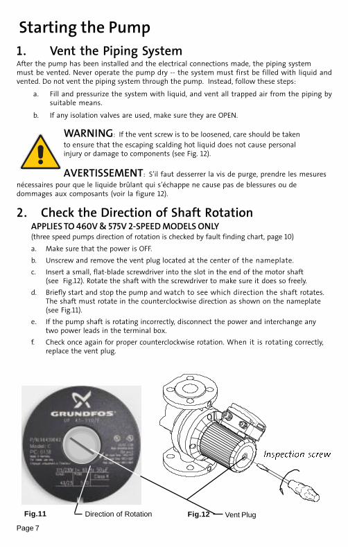
3b. Speed Selection (two speed, 3 x 460V & 575V)The speed setting in the terminal box (see Fig.13) can be changed to two positions. Thespeed in the two positions appears in the table below (also see Fig.13 on page 8).
Speed Step Speed in % of Maximum Speed1 approx. 75%2 100%
WARNING: Never make any connections in the pump terminal box
unless the electrical supply has been switched off.
AVERTISSEMENT: Ne jamais établir de connexions dans la boîte dejonction de la pompe à moins que l’alimentation électrique n’ait été coupée.
Change the pump performance as follows:The speed is changed by the position of the bridges in the terminals. The bridgesare fitted according to:
• Figure 15 for speed 1 - Low speed• Figure 16 for speed 2 - High speed
Starting the Pump
Fig.16
Fig.15
L1L2L3P1P2T6T4T5 T1T2T3
Fig.17
Page 9
Jumper Wire
Jumper Wire

Troubleshooting1. Fault Finding Chart
WARNING: Before removing the terminal box cover, make sure that the electrical supply hasbeen switched off and that it cannot be accidentally switched on.
WARNING: The pumped liquid may be scalding hot and under high pressure. Before any
removal or dismantling of the pump, the system must be drained or the isolating valves on bothsides of the pump must be closed.
AVERTISSEMENT: Avant de retirer le couvercle de la boîte de jonction,s’assurer que l’alimentation électrique a été coupée et ne peut être rétablie
accidentellement.
AVERTISSEMENT: Le liquide pompé peut être brûlant et sous haute pression. Avant de retirer ou dedémonter la pompe, il faut drainer le système ou fermer les deux robinets d’isolement latéraux de la pompe.
Fault
The pump does not run.None of the indicator lights areon.
The pump does not run.The green indicator light is on.
Three-Phase Pumps Only:The pump is running. The red andgreen indicator lights are on.
Noise in the system. The greenindicator light is on.
Noise in the pump. The greenindicator light is on.
Insufficient heat in some placesin the heating system.
Single phase pumps with protec-tion module (only).
The Pump does not run.
The red indicator light is on.
The green indicator light is off.
Cause
One fuse in the installation is blown.
External circuit breaker is switchedoff.
Current/Voltage operated groundfault interrupter has tripped.
The pump's internal thermal over-load switch has cut out
( Standard module only).
Rotor blocked, but the pump hasn'tbeen cut out by the thermal overloadswitch.The speed switch module has notbeen fitted.
The pump is running with the wrongdirection of rotation.
Air in the system.The pump flow is too high.The pressure is too high.
Air in the pump.
The inlet pressure is too low.
The pump performance is too low.
The pump has been cut out by thethermal overload switch due to highliquid temperature or blocked rotor.
The speed switch module has notbeen fitted.
Remedy
Replace the fuse.
Switch the circuit breaker on.
Repair the insulation defects and reset the circuit breaker.
Check that the liquid temperature falls within the specified range.With external on/off changeover contact: The pump willrestart automatically when it has cooled to the normal tempera-ture.With external on/off impulse contacts: The pump can berestarted when it has cooled to normal temperature.
Switch off the electricity supply and clean/repair the pump.
Switch off the electricity supply at the external circuit breakerand fit the speed switch module into position.
Switch off the electricity supply at the external circuit breakerand interchange any two phases (leads) in the pump terminalbox.
Vent the system.Reduce the pump performance.Reduce the pump performance.
Vent the pump.
Increase the inlet pressure and/or check the air volume in theexpansion tank (if installed).
Increase the pump performance, if possible, or replace the pumpwith a pump with higher flow.
Check that the liquid temperature falls within the speciedrange.The pump will restart automatically when it has cooled tonormal temperature.
Note: If the thermal overload switch has cut out the pump threetimes within a short period, the pump must be restarted manu-ally by switching off the electrical suply.
Switch off the electrical supply by means of the external mainsswitch and fit the speed switch module.
Page 10

������������ Preliminary ChecksSupply VoltageTo check the voltage being supplied to the motor, use a voltmeter. Be careful, sincepower is still being supplied to the pump. Do not touch the voltmeter leads togetherwhile they are in contact with the power lines.
Three Phase MotorsTouch a voltmeter lead to:• Power leads L1 and L2• Power leads L2 and L3• Power leads L3 and L1
Single Phase MotorsTouch one voltmeter lead to each of the lines supplyingpower to the pump L1 and L2 , (or L1 and N for 115V circuits).
EvaluationWhen the motor is under load, the voltage should be within 10% (+ or -) of thenameplate voltage. Any variation larger than this may indicate a poor electrical supplyand can cause damage to the motor windings. The motor should not be operatedunder these conditions. Contact your power supplier to correct the problem or changethe motor to one requiring the voltage you are receiving.
Current MeasurementTo check the current, use an ammeter. To do so, follow these steps:
1. Make sure the pump is operating
2. Set the ammeter to the proper scale.
3. Place the tongs of the ammeter around the leg to be measured.
4. Compare the results with the amp draw information onthe motor nameplate.
5. Repeat for the other legs.
EvaluationIf the current draw exceeds the listed nameplate amps, or ifthe current imbalance is greater than 5% between each leg onthree phase units, then check the following:
• The voltage supplied to the pump maybe too high or toolow.
• The contacts on the motor starter may be burned.
• The terminals in the starter or terminal box may beloose.
• There may be a winding defect. Check the winding andinsulation resistance
• The motor windings may be shorted or grounded.
} These tests should give areading of full line voltage.
CheckingSingle Phase
Power
L1 L2
Page 11
Fig.19
Fig.18

Troubleshooting
Insulation Resistance (lead-to-ground)
To check the insulation resistance (lead-to-ground) of the motor and leads, amegohmmeter is required.
1. Turn the POWER OFF.
2. Disconnect all electrical leads tothe motor.
3. Set the scale selector on themegohmmeter to R x 100K,touch its leadstogether, and adjustthe indicator tozero.
4. Touch the leads ofthe megohmmeterindividually to eachof the motor leadsand to ground (i.e.L1 to ground; L2 toground, etc.).
Evaluation: The resistance values for newmotors must exceed 1,000,000 ohms. If they do not, replace the motor.
Fig.20
Page 12
Page 13
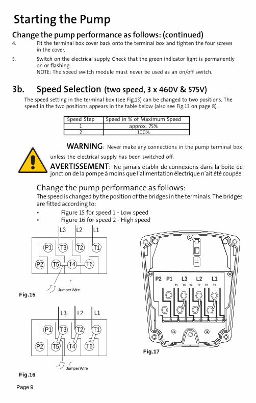
Winding Resistance (line to line)To check the winding resistance of the motor windings, a
megohmmeter is required.
1. Turn the power off
2. Disconnect all electrical leads to the motor.3. Set the scale on the megohmmeter to Rx1, touch its leads together
and adjust the indicator to zero.4. Using the charts below for reference, touch the leads of the
megohmmeter to the appropriate pair of connectors. Check all pairsthat are present and write down and label (R
A, R
SI, R
S2, R) all readings.
5. Compare your readings to the matching model, phase and voltageon the chart on page 15.
Evaluation : The resistance values must fall within the tolerances listed on the
next page. If they do not, replace the motor.
Internal WiringUPS
Terminal plug in stator
Single Phase Three Phase 208-230V
RA: 6-1 or 6-1, 7-2
RS1
: 12-8 or 12-8, 14-9R
S2: 4-10 or 4-10, 5-11
R: 5-9 or 5-9, 7-14R: 11-12 or 11-12, 1-10R: 4-6 or 4-6, 8-2
A: Main winding
S2: Auxiliary winding
S1: Auxiliary winding
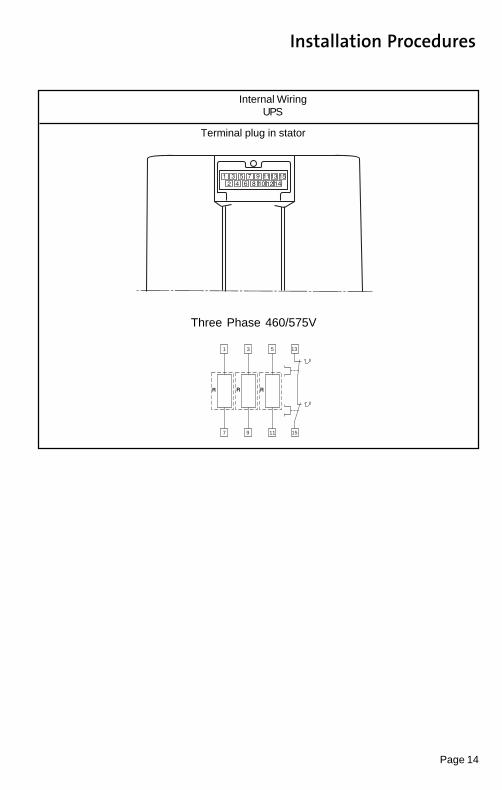
Internal WiringUPS
Terminal plug in stator
Three Phase 460/575V
1
7
3
9
5
11
13
15
Installation Procedures
Page 14

Winding Resistance Chart
[�] 20°C - 50°C
Page 15
����� �����
��������� �� �� � �� ��� ������������ ����� � �� ����� � �� ��� � � �������� �� � � � � ���� ��� � � � ����� � ��
��������� ���� ���� �� �� � ��������� �� �� � ��� ��������� ���� ��� ��������� ����� � ��� �� �� � �� ��� � � ��� ����� �� ����� � ��� ����� � ��� ���� � ����
��������� ���� ���� �� ��� � � ���������� �� ����� � �� ��������� ��� ������������� ����� � ���� �� � � ���� ���� � ��� ����� �� ��� � � � �� � � � �� �� �� � ����
�������� � ���� ���� �� �� � � ��� ������ �� ����� � � � ��������� ����� � �� ��������� ����� � ��� ���� � ���� ��� � � ��������� �� � ��� � ���� ��� � � ���� ���� � ���
�������� ���� ���� �� ���� ���������� �� ��� ��� ��������� �� � ������������� ��� � � ���� ����� � �� ��� � � ��� ����� �� ��� � � ���� ����� � �� ����� � ���
�������� ���� ���� �� �� � � �� ������ �� ��� � � ��� ��������� � � ������������ ����� � ���� ����� � ��� ��� � � ��������� �� ��� � � � �� �� �� � �� ��� � � �� �
�������� ���� ���� �� ����� � ��� ������ �� � ��� � ������������ ���� ������������ ���� � ���� ��� � � ���� ����� � �������� �� ��� � � ���� � � � ��� ����� � ����
������� � ���� ���� �� ��� � � � ������ �� ����� � ������������� �� � � ��� ����� �� ��� � � ���� � � � ��� ��� � � ����
��������� ���� ���� �� ��� � � ���������� �� � � � �� ��������� ��� � � ������������� ����� � ���� ��� � �� ��� � � ��������� �� �� � � ��� ��� � � � �� ��� � � ����
�������� ���� ���� �� ����� � ��� ������ �� ���� ������������� ���� ����������� ����� � ���� �� � � ���� ���� � ��� ����� �� ��� � � � �� � � � �� �� �� � ����
�������� ���� ���� �� �� � � ��� ������ �� ����� � � � ��������� ����� � �� ��������� ���� � ��� ����� � �� ���� � ��������� �� ��� � � ��� ���� � ��� ����� � ���
�������� ���� ���� �� ��� � � ��� ������ �� ��� � � � ���������� � � ��������� �� ��� � � ���� � � � ��� ��� � � ����
������� � ���� ���� �� ���� � ��������� �� ��� � ������������� ����� � �������� ���� �� ��� � � � �
��������� ������ �� ����� � ����������� �� � � ��� ���� ���� �� ����� � ���
�������� ������ �� � ��� � ������������ ���� ���
�������� ���� ���� �� ���� � ���
���� ���� �� ��� � � � ��������� � ������ �� ����� � ��
��������� �� � � ��� ���� ���� �� ���� � ���
�������� ������ �� ����� � ������������� ��� � � ���

Page 16
Replacing Components
Fig. 21
Replacing the Pump Head Removal
1. Disconnect or TURN OFF the power supply.
2. Close any isolation valves on either side of the pump to avoid draining thesystem of liquid.
3. Disconnect the electrical leads from the terminal box.
4. Disconnect and remove the conduit from the terminal box.
5. Loosen and remove the four allen screws (8 or 10 mm) which connect thepump head housing to the pump housing.
6. Remove the pump head from the pump housing.
7. Clean the machined surfaces in the pump housing of any foreign material.
Installation
1. Carefully remove the new pump head assembly from its packaging.Separate the impeller/rotor assembly from the new pump head.
2. While holding the thrust bearing, carefully place the impeller/rotor assem-bly into the pump housing. The bearing plate should fit snugly into thelowest machined surface in the pump housing.
3. Make sure that the impeller/rotor assembly can rotate freely.
4. Place the O-Ring over the rotor and locate it into the inner diameter of thepump housing.
5. Carefully place the pumphead housing over the rotor and rotate it so theterminal box is in the position you wish (see page 3 for positioning).
6. Make sure the pump head housing is properly seated on the pumphousing. Do not force the two together -- if there is binding, disassemblethem and repeat steps 2-6. Tighten the allen screws evenly to secure thepump head. Torque to: 8mm ............. 15 ft lbs
10mm ............. 25 ft lbs
7. Check to make sure the motor shaft turns freely, as explained in step 5 onpage 3 (under "Rotating the Terminal Box").

Page 17
1. Before replacing the terminal box or capacitor, make sure thepower is OFF.
2. Remove the terminal box cover by completely loosening all fourtorx/standard screws.
3. Remove the speed switch (noting its position) by pulling firmlyand evenly on both sides of it. (Not for 460/575 V)
a.4. (Capacitor replacement, single-phase only) Disconnect the twoconnector clips from the capacitor and unscrew the completeplastic strain relief nut. Remove capacitor wire and strain relief.
a.5. Screw in new complete strain relief nut and connect new clipconnectors. Pull excess sheathed cable out of terminal box, beingsure to leave at least 1/
8" of sheath inside of terminal box.
b.4. (Terminal box replacement, single-phase and three-phase)Disconnect all wiring, remove the three phillips-head screws holding the terminal box in place and remove the terminal box by pullingfirmly and evenly on both side.
b.5. Check that the clear rubber gasket is in place around the terminal boxconnector stem, carefully press the terminal box into the stator socket,replace the three phillips-head terminal box screws and replace wiring.
6. Replace the speed switch to its proper position, making sure to push it all the way in. (Not for 460/575V)
7. Replace the terminal box cover and tighten all four torx/standardscrews.
8. Switch on electrical power supply. The pump is now ready foroperation.
Replacing Components
Replacing the Terminal Box or Capacitor
If the terminal box is replaced,make certain the electrical in-for-mation listed on the new boxmatches the information listed onthe old box, and that it is compat-ible with the pump and incomingelectrical supply.
For all terminal boxes, it is veryimportant to tightly secure theframe ground-ing screw throughthe terminal box, so that a properconnection between the terminalbox and motor is made.
SpeedSwitch
StandardModule
ElectricalInformation
Frame GroundScrew Hole
All {{
{
{
Capacitor
TerminalBox
All
Fig.22

Page 18
Notes

LIMITED WARRANTY
Products manufactured by (GRUNDFOS) GRUNDFOS PUMPS CORPORATION arewarranted to the original user only to be free of defects in material and workmanshipfor a period of 18 months from date of installation, but not more than 24 months fromdate of manufacture. GRUNDFOS' liability under this warranty shall be limited torepairing or replacing at GRUNDFOS' option, without charge, F.O.B. GRUNDFOS' factoryor authorized service station, any product of GRUNDFOS' manufacture. GRUNDFOSwill not be liable for any costs of removal, installation, transportation, or any othercharges which may arise in connection with a warranty claim. Products which are soldbut not manufactured by GRUNDFOS are subject to the warranty provided by themanufacturer of said products and not by GRUNDFOS' warranty. GRUNDFOS will notbe liable for damage or wear to products caused by abnormal operating conditions,accident, abuse, misuse, unauthorized alteration or repair, or if the product was notinstalled in accordance with GRUNDFOS' printed installation and operatinginstructions.
To obtain service under this warranty, the defective product must be returned to thedistributor or dealer of GRUNDFOS' products from which it was purchased togetherwith proof of purchase and installation date, failure date, and supporting installationdata. Unless otherwise provided, the distributor or dealer will contact GRUNDFOS oran authorized service station for instructions. Any defective product to be returned toGRUNDFOS or a service station must be sent freight prepaid; documentation support-ing the warranty claim and/or a Return Material Authorization must be included if soinstructed.
GRUNDFOS WILL NOT BE LIABLE FOR ANY INCIDENTAL OR CONSEQUENTIALDAMAGES, LOSSES, OR EXPENSES ARISING FROM INSTALLATION, USE, OR ANY OTHERCAUSES. THERE ARE NO EXPRESS OR IMPLIED WARRANTIES, INCLUDING MERCHANT-ABILITY OR FITNESS FOR A PARTICULAR PURPOSE, WHICH EXTEND BEYOND THOSEWARRANTIES DESCRIBED OR REFERRED TO ABOVE.
Some jurisdictions do not allow the exclusion or limitation of incidental or consequen-tial damages and some jurisdictions do not allow limitations on how long implied war-ranties may last. Therefore, the above limitations or exclusions may not apply to you.This warranty gives you specific legal rights and you may also have other rights whichvary from jurisdiction to jurisdiction.
L-UPS-TL-001 Rev.03/03PRINTED IN U.S.A.
96459998
Bombas Grundfos de Mexico, S.A. de C.V.Boulevard TLC #15, Parque Industrial Stiva AeropuertoC.P. 66600 Apodaca, N.L. MexicoTelephone: 52-81-8144-4000Fax: 52-81-8144-4010
Grundfos Canada, Inc.2941 Brighton Rd.Oakville, Ontario L6H 6C9Telephone: (905) 829-9533Fax: (905)829-9512
Grundfos Pumps Corporation17100 W.118th TerraceOlathe, Kansas 66061Telephone: (913) 227-3400Fax: (913)227-3500
www.grundfos.com
![Grundfos UP 20-15 N 150 pump - lenntech.com · UP20-15 N 150 3x400V 50Hz 9H Grundfos Pump 59641800 ... Norwegian NRF no.: NRF NO 9042177. Printed from Grundfos Product Centre [2018.02.043]](https://img.dokumen.tips/doc/110x75/5bb3b8d509d3f2c0138bb603/grundfos-up-20-15-n-150-pump-up20-15-n-150-3x400v-50hz-9h-grundfos-pump-59641800.jpg)
![Grundfos SL1.50.65.22.2.50D.C pump - Lenntech › uploads › grundfos › 98624257 › ...Printed from Grundfos Product Centre [2018.06.003] Position Qty. Description 1 SL1.50.65.22.2.50D.C](https://img.dokumen.tips/doc/110x75/60ce95cbe9a1406f7c619e35/grundfos-sl1506522250dc-pump-lenntech-a-uploads-a-grundfos-a-98624257.jpg)