Embed Size (px)
Citation preview
Hydro 1000Installation and operating instructions
GRUNDFOS INSTRUCTIONS
Declaration of Conformity We Grundfos declare under our sole responsibility that the products Hydro 1000, to which this dec-laration relates, are in conformity with the Council Directives on the approximation of the laws of the EC Member States relating to:— Machinery (98/37/EC).
Standard used: EN ISO 12100.— Electromagnetic compatibility (89/336/EEC).
Standards used: EN 61 000-6-2 and EN 61 000-6-3. — Electrical equipment designed for use within certain voltage limits
(73/23/EEC) [95].Standard used: EN 60 204-1.
Bjerringbro, 1st April 2005
Jan StrandgaardTechnical Director
2
CONTENTSPage
1. General 31.1 Applications 31.2 Operating conditions 3
2. Product description 32.1 Grundfos Hydro 1000 32.2 Grundfos Control 1000 32.3 Monitoring and indication functions 42.4 Example of booster set Hydro 1000 4
3. Operation 43.1 CS 1000 front cover 4
4. Installation 54.1 Location 54.2 Foundation 54.3 Pipework 54.4 Dry-running protection 54.5 Priming 54.6 Electrical connection 5
5. Settings 55.1 Timers 55.2 Operation selection 65.3 Alarm resetting 75.4 Pressure setting 75.5 Pressure switch 75.6 Tank precharge pressure 7
6. Start-up 87. Maintenance 87.1 Maintenance of booster set 87.2 Maintenance of Control 1000 87.3 Checking the precharge pressure 8
8. Fault finding chart 98.1 Emergency operation 9
9. Parts list 1010. Technical data 1010.1 Sound pressure level 1010.2 Hydraulic data 1010.3 Electrical data 10
Before beginning installation procedures, these in-stallation and operating instructions should be stud-ied carefully. The installation and operation should also be carried out in accordance with local regula-tions and accepted codes of good practice.
1. General
1.1 ApplicationsGrundfos booster sets Hydro 1000 are designed for the transfer and pressure boosting of clean water in waterworks, blocks of flats, hotels, industry, hospitals, schools, etc.
1.2 Operating conditionsLiquid temperature: Maximum +50°C.
Ambient temperature: 0°C to +40°C.
Operating pressure: Maximum 10 bar.
Minimum and maximuminlet pressures: See installation and operating
instructions for CR pumps.
Liquid temperature and operating pressure may be limited by the diaphragm tank.
2. Product description
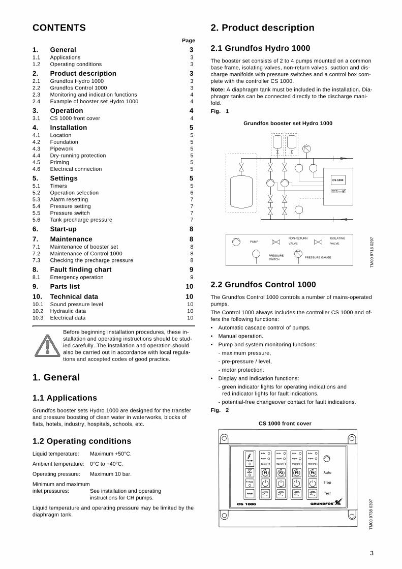
2.1 Grundfos Hydro 1000The booster set consists of 2 to 4 pumps mounted on a common base frame, isolating valves, non-return valves, suction and dis-charge manifolds with pressure switches and a control box com-plete with the controller CS 1000. Note: A diaphragm tank must be included in the installation. Dia-phragm tanks can be connected directly to the discharge mani-fold.Fig. 1
2.2 Grundfos Control 1000The Grundfos Control 1000 controls a number of mains-operated pumps.The Control 1000 always includes the controller CS 1000 and of-fers the following functions:• Automatic cascade control of pumps.• Manual operation.• Pump and system monitoring functions:
- maximum pressure,- pre-pressure / level,- motor protection.
• Display and indication functions:- green indicator lights for operating indications and
red indicator lights for fault indications,- potential-free changeover contact for fault indications.
Fig. 2
TM00
971
8 02
97TM
00 9
738
0397
VALVE
CS 1000
PRESSURE GAUGE
NON-RETURN
VALVE
ISOLATINGPUMP
PRESSURESWITCH
Hydro 1000
Grundfos booster set Hydro 1000
CS 1000 front cover
3

2.3 Monitoring and indication functionsThe following functions are available:• Red indicator lights (LED) for indication of fault conditions:
- maximum pressure (if a pressure switch is installed),- dry-running protection (if a pressure switch is installed),- motor protection.
• Green indicator lights (LED) for indication of operating condi-tions:- power on,- automatic operation,- pump in operation.
• Potential-free changeover contact for fault indications.
2.4 Example of booster set Hydro 1000
3. Operation
3.1 CS 1000 front coverThe CS 1000 front cover shows all possible operating conditions.Fig. 3
Grundfos Hydro 1000 CSFour identical full-size mains-operated pumps and a dia-phragm tank.
TM00
808
4 23
96
One pump in operation.
TM00
808
5 23
96
Three pumps in operation.
TM00
508
6 23
96
Grundfos Hydro 1000 CS maintains an almost constant pres-sure by cutting in/out the required number of pumps.The CS 1000 alters the starting sequence of the pumps after each pump stop, thus giving all pumps equal operating time.Pump changeover is automatic and depends on load and fault.
CS 1000
Q
stop H
Hstart
H
Cut-out
Cut-in
H
start
Q
stop H
H
Cut-out
Cut-in
TM00
973
8 03
97
Button/indicator light Function
Power indication. The green indicator light is on when the electricity supply to the CS 1000 is connected.
Dry-running alarm. The red indicator light is on when the dry-running alarm is activated. The light goes out when the alarm is reset. If automatic resetting is chosen, the indica-tor light goes out automatically when nor-mal operating conditions are achieved.
Maximum pressure alarm. The red indicator light is on when maximum pressure is acti-vated. The light goes out when the alarm is reset. If automatic resetting is chosen, the indicator light goes out automatically when normal operating conditions are achieved.
Reset button. Resets the dry-running alarm and the maximum pressure alarm if auto-matic resetting has not been chosen.
Automatic operation. The green indicator light is on when the pump is released and ready for operation.
Pump alarm. The red indicator light is on when the thermal relay of the pump is acti-vated. The pump is out of operation. The alarm can be reset on the thermal relay.
Pump in operation. The green indicator light is on when the pump is operating.
Auto button. When the auto button is pressed, the pump will be released for op-eration and the indicator light for automatic operation will be lit.
Stop button. When the stop button is pressed, the pump will be taken out of op-eration and the indicator light for automatic operation goes out.
Test button. The pump is operating as long as the test button is pressed. The maxi-mum pressure and the dry-running protec-tion are not activated as long as the button is pressed.
CS 1000 front cover
4
4. Installation
4.1 LocationThe booster set should be placed in a well-ventilated room to en-sure adequate cooling of the pump motors. It should be placed with a 1 metre clearance in front and on the two sides.Use a fork-lift truck to move the booster set.
4.2 FoundationThe booster set does not require a special foundation, but it shouldbe positioned on a plane and solid surface, e.g. a concrete floor.
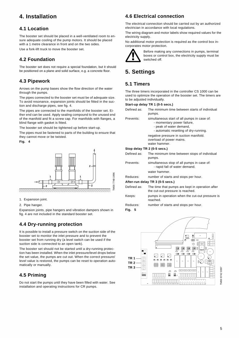
4.3 PipeworkArrows on the pump bases show the flow direction of the water through the pumps.The pipes connected to the booster set must be of adequate size. To avoid resonance, expansion joints should be fitted in the suc-tion and discharge pipes, see fig. 4.The pipes are connected to the manifolds of the booster set. Ei-ther end can be used. Apply sealing compound to the unused end of the manifold and fit a screw cap. For manifolds with flanges, a blind flange with gasket is fitted.The booster set should be tightened up before start-up.The pipes must be fastened to parts of the building to ensure that they cannot move or be twisted.Fig. 4
1. Expansion joint.
2. Pipe hanger.Expansion joints, pipe hangers and vibration dampers shown in fig. 4 are not included in the standard booster set.
4.4 Dry-running protectionIt is possible to install a pressure switch on the suction side of the booster set to monitor the inlet pressure and to prevent the booster set from running dry (a level switch can be used if the suction side is connected to an open tank). The booster set should not be started until a dry-running protec-tion has been installed. When the inlet pressure/level drops below the set value, the pumps are cut out. When the correct pressure/level value is restored, the pumps can be reset to operation auto-matically or manually.
4.5 PrimingDo not start the pumps until they have been filled with water. See installation and operating instructions for CR pumps.
4.6 Electrical connectionThe electrical connection should be carried out by an authorized electrician in accordance with local regulations.The wiring diagram and motor labels show required values for the electricity supply.No additional motor protection is required as the control box in-corporates motor protection.
5. Settings
5.1 TimersThe three timers incorporated in the controller CS 1000 can be used to optimize the operation of the booster set. The timers are to be adjusted individually.Start-up delay TR 1 (0-5 secs.)Defined as: The minimum time between starts of individual
pumps.Prevents: simultaneous start of all pumps in case of:
- momentary power failure,- peak of water demand,- automatic resetting of dry-running.
negative pressure in suction manifold.overload of power mains.water hammer.
Stop delay TR 2 (0-5 secs.)Defined as: The minimum time between stops of individual
pumps.Prevents: simultaneous stop of all pumps in case of:
- rapid fall of water demand.water hammer.
Reduces: number of starts and stops per hour.After-run delay TR 3 (0-5 secs.)Defined as: The time that pumps are kept in operation after
the cut-out pressure is reached.Keeps: pumps in operation when the cut-out pressure is
reached.Reduces: number of starts and stops per hour.Fig. 5
TM00
774
8 19
96
2
2
11
2
Before making any connections in pumps, terminal boxes or control box, the electricity supply must be switched off.
TM00
974
2 03
97
J2 J4
TR 1TR 2TR 3
5
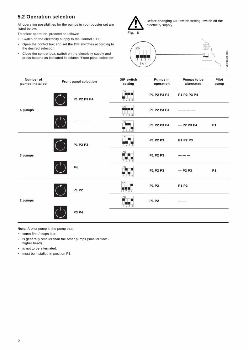
5.2 Operation selectionAll operating possibilities for the pumps in your booster set are listed below:To select operation, proceed as follows:• Switch off the electricity supply to the Control 1000.• Open the control box and set the DIP switches according to
the desired selection.• Close the control box, switch on the electricity supply and
press buttons as indicated in column “Front panel selection”.
Fig. 6
Note: A pilot pump is the pump that:• starts first / stops last.• is generally smaller than the other pumps (smaller flow -
higher head).• is not to be alternated.• must be installed in position P1.
Before changing DIP switch setting, switch off the electricity supply.
TM03
064
9 04
05
ON
1 2 3 4
ON
SW 1
1 2 3 4
Number of pumps installed Front panel selection DIP switch
settingPumps inoperation
Pumps to be alternated
Pilot pump
4 pumps
P1 P2 P3 P4P1 P2 P3 P4 P1 P2 P3 P4
P1 P2 P3 P4 — — — —
— — — —P1 P2 P3 P4 — P2 P3 P4 P1
3 pumps
P1 P2 P3P1 P2 P3 P1 P2 P3
P1 P2 P3 — — —
P4P1 P2 P3 — P2 P3 P1
2 pumps
P1 P2P1 P2 P1 P2
P1 P2 — —
P3 P4
6
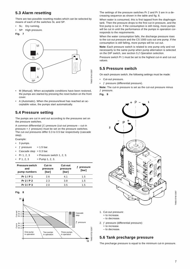
5.3 Alarm resettingThere are two possible resetting modes which can be selected by means of each of the switches SL and SP.• SL: Dry running.• SP: High pressure.Fig. 7
• M (Manual). When acceptable conditions have been restored, the pumps are started by pressing the reset button on the front cover.
• A (Automatic). When the pressure/level has reached an ac-ceptable value, the pumps start automatically.
5.4 Pressure settingThe pumps are cut in and out according to the pressures set on the pressure switches.A common differential (ƒ) pressure (cut-out pressure – cut-in pressure = ƒ pressure) must be set on the pressure switches. The cut-out pressures differ 0.3 to 0.5 bar respectively (cascade step).Example:• 3 pumps.• ƒ pressure = 1.5 bar.• Cascade step = 0.3 bar.• Pr 1, 2, 3 = Pressure switch 1, 2, 3.• P 1, 2, 3 = Pump 1, 2, 3.
Fig. 8
The settings of the pressure switches Pr 2 and Pr 3 are in a de-creasing sequence as shown in the table and fig. 8.When water is consumed, this is first tapped from the diaphragm tank. Then the pressure drops to the first cut-in pressure, and the first pump is cut in. If the consumption is still rising, more pumps will be cut in until the performance of the pumps in operation cor-responds to the requirements.When the water consumption falls, the discharge pressure rises to the cut-out pressure and the CS 1000 cuts out one pump. If the consumption is still falling, more pumps will be cut out.Note: Each pressure switch is related to one pump only and not necessarily to the same pump when pump alternation is selected on the DIP switch, see section 5.2 Operation selection.Pressure switch Pr 1 must be set to the highest cut-in and cut-out values.
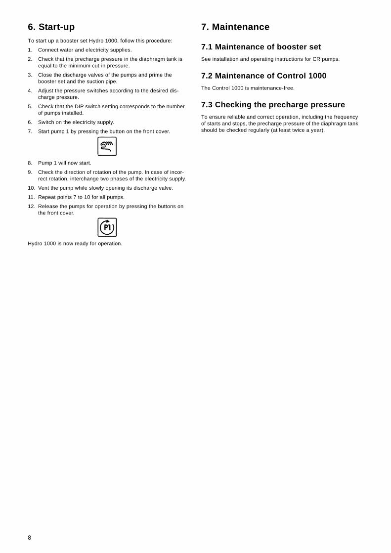
5.5 Pressure switchOn each pressure switch, the following settings must be made:
• Cut-out pressure.• ƒ pressure (differential pressure).Note: The cut-in pressure is set as the cut-out pressure minus ƒ pressure.Fig. 9
1. Cut-out pressure:+ to increase.– to decrease.
2. ƒ pressure (differential pressure):+ to increase.– to decrease.
5.6 Tank precharge pressureThe precharge pressure is equal to the minimum cut-in pressure.
TM00
974
4 03
97
Pressure switch and
pump numbers
Cut-in pressure
[bar]
Cut-out pressure
[bar]
ƒ pressure[bar]
Pr 1 / P 1 2.6 4.1 1.5Pr 2 / P 2 2.3 3.8 1.5Pr 3 / P 3 2.0 3.5 1.5
TM00
973
2 02
97
SL
SP
Pr 1Pr 2Pr 3
Pr 1Pr 2Pr 3
Cut
-out
Cut
-in
ƒ pressure
Cascadestep
One pump in operation
Two pumpsin operation
Three pumps in operation
TM00
974
0 03
97
1
2
7
6. Start-upTo start up a booster set Hydro 1000, follow this procedure:
1. Connect water and electricity supplies.
2. Check that the precharge pressure in the diaphragm tank is equal to the minimum cut-in pressure.
3. Close the discharge valves of the pumps and prime the booster set and the suction pipe.
4. Adjust the pressure switches according to the desired dis-charge pressure.
5. Check that the DIP switch setting corresponds to the number of pumps installed.
6. Switch on the electricity supply.
7. Start pump 1 by pressing the button on the front cover.
8. Pump 1 will now start.
9. Check the direction of rotation of the pump. In case of incor-rect rotation, interchange two phases of the electricity supply.
10. Vent the pump while slowly opening its discharge valve.
11. Repeat points 7 to 10 for all pumps.
12. Release the pumps for operation by pressing the buttons on the front cover.
Hydro 1000 is now ready for operation.
7. Maintenance
7.1 Maintenance of booster setSee installation and operating instructions for CR pumps.
7.2 Maintenance of Control 1000The Control 1000 is maintenance-free.
7.3 Checking the precharge pressureTo ensure reliable and correct operation, including the frequency of starts and stops, the precharge pressure of the diaphragm tank should be checked regularly (at least twice a year).
8

8. Fault finding chart
8.1 Emergency operationIn case of damage to electronic components belonging to the printed circuit board, the system can be operated by moving the multiplug from J2 to J4, see fig. 10.Pumps will still operate automatically by pressure switches but without LED indications and the alternation function.Maximum pressure and dry-running protection are not active when the booster set is in emergency operation.
Fig. 10
Before making any connections in pumps, terminal boxes or control box, the electricity supply must be switched off.
Fault Cause Remedy
1. Motor does not run when started.
a) Electricity supply disconnected. Connect the electricity supply.
b) Automatic circuit breakers cut out. Correct the fault and cut in the automatic circuit break-ers.
c) Fuse in the CS 1000 defective. Replace the fuse.
d) Motor defective. Repair/replace the motor.
2. Motor starts, but stops immediately after-wards.
a) Incorrect setting of pressure switch. Increase the cut-out pressure and/or differential pressure.
b) Wrong diaphragm tank precharge pressure. Check the diaphragm tank precharge pressure.
3. Frequent starts and stops.
a) Incorrect setting of time delay TR 2. Set the time delay TR 2 accordingly.
b) Incorrect setting of pressure switch. Increase the cut-out pressure and/or differential pressure.
c) Diaphragm tank defective. Repair the diaphragm tank.
4. Pumps are running but deliver no water.
a) Suction pipe/pumps blocked by impurities. Clean the suction pipe/pumps.
b) Non-return valve blocked in closed position. Clean the non-return valve.
c) Suction pipe leaky. Repair the suction pipe.
d) Air in suction pipe/pumps. Vent the pumps. Check the suction pipe for leakages.
e) Motors running with the wrong direction of rota-tion.
Change the direction of rotation.
5. Leakage from the shaft seal.
a) Shaft seal defective. Replace the shaft seal.
b) Height adjustment of the pump shaft inaccurate. Readjust the shaft height. See installation and oper-ating instructions for CR pumps.
6. Noise. a) The pumps are cavitating. Clean the suction pipe/pumps and possibly the suc-tion strainer.
b) The pumps do not rotate freely (frictionalresistance) due to inaccurate height adjust-ment of the pump shaft.
Readjust the shaft height. See installation and oper-ating instructions for CR pumps.
TM00
974
2 03
97J2 J4
J2 J4
9
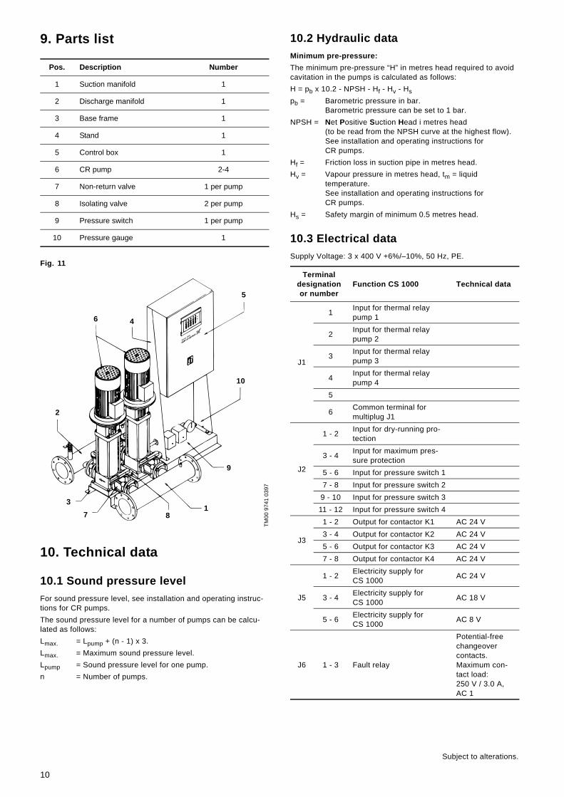
9. Parts list
Fig. 11
10. Technical data
10.1 Sound pressure levelFor sound pressure level, see installation and operating instruc-tions for CR pumps.The sound pressure level for a number of pumps can be calcu-lated as follows:Lmax. = Lpump + (n - 1) x 3.Lmax. = Maximum sound pressure level.Lpump = Sound pressure level for one pump.n = Number of pumps.
10.2 Hydraulic dataMinimum pre-pressure:The minimum pre-pressure “H” in metres head required to avoid cavitation in the pumps is calculated as follows:H = pb x 10.2 - NPSH - Hf - Hv - Hspb = Barometric pressure in bar.
Barometric pressure can be set to 1 bar.NPSH = Net Positive Suction Head i metres head
(to be read from the NPSH curve at the highest flow).See installation and operating instructions forCR pumps.
Hf = Friction loss in suction pipe in metres head.Hv = Vapour pressure in metres head, tm = liquid
temperature.See installation and operating instructions forCR pumps.
Hs = Safety margin of minimum 0.5 metres head.
10.3 Electrical dataSupply Voltage: 3 x 400 V +6%/–10%, 50 Hz, PE.
Pos. Description Number
1 Suction manifold 1
2 Discharge manifold 1
3 Base frame 1
4 Stand 1
5 Control box 1
6 CR pump 2-4
7 Non-return valve 1 per pump
8 Isolating valve 2 per pump
9 Pressure switch 1 per pump
10 Pressure gauge 1
TM00
974
1 03
97
Hydro 1000
5
10
46
2
9
187
3
Terminal designation or number
Function CS 1000 Technical data
J1
1 Input for thermal relay pump 1
2 Input for thermal relay pump 2
3 Input for thermal relay pump 3
4 Input for thermal relay pump 4
5
6 Common terminal for multiplug J1
J2
1 - 2 Input for dry-running pro-tection
3 - 4 Input for maximum pres-sure protection
5 - 6 Input for pressure switch 17 - 8 Input for pressure switch 2
9 - 10 Input for pressure switch 311 - 12 Input for pressure switch 4
J3
1 - 2 Output for contactor K1 AC 24 V3 - 4 Output for contactor K2 AC 24 V5 - 6 Output for contactor K3 AC 24 V7 - 8 Output for contactor K4 AC 24 V
J5
1 - 2 Electricity supply for CS 1000 AC 24 V
3 - 4 Electricity supply for CS 1000 AC 18 V
5 - 6 Electricity supply for CS 1000 AC 8 V
J6 1 - 3 Fault relay
Potential-free changeover contacts.Maximum con-tact load: 250 V / 3.0 A, AC 1
Subject to alterations.
10
DenmarkGRUNDFOS DK A/S Poul Due Jensens Vej 7A DK-8850 Bjerringbro Tlf.: +45-87 50 50 50 Telefax: +45-87 50 51 51 E-mail: [email protected]/DKArgentinaBombas GRUNDFOS de Argentina S.A.Ruta Panamericana km. 37.500 Lote 34A1619 - GarinPcia. de Buenos AiresPhone: +54-3327 414 444Telefax: +54-3327 411 111AustraliaGRUNDFOS Pumps Pty. Ltd. P.O. Box 2040 Regency Park South Australia 5942 Phone: +61-8-8461-4611 Telefax: +61-8-8340 0155 AustriaGRUNDFOS Pumpen Vertrieb Ges.m.b.H.Grundfosstraße 2 A-5082 Grödig/Salzburg Tel.: +43-6246-883-0 Telefax: +43-6246-883-30 BelgiumN.V. GRUNDFOS Bellux S.A. Boomsesteenweg 81-83 B-2630 Aartselaar Tél.: +32-3-870 7300 Télécopie: +32-3-870 7301BrazilGRUNDFOS do Brasil Ltda.Rua Tomazina 106CEP 83325 - 040Pinhais - PRPhone: +55-41 668 3555Telefax: +55-41 668 3554CanadaGRUNDFOS Canada Inc. 2941 Brighton Road Oakville, Ontario L6H 6C9 Phone: +1-905 829 9533 Telefax: +1-905 829 9512 ChinaGRUNDFOS Pumps (Shanghai) Co. Ltd.22 Floor, Xin Hua Lian Building755-775 Huai Hai Rd, (M)Shanghai 200020PRCPhone: +86-512-67 61 11 80Telefax: +86-512-67 61 81 67Czech RepublicGRUNDFOS s.r.o.Cajkovského 21779 00 OlomoucPhone: +420-585-716 111Telefax: +420-585-438 906FinlandOY GRUNDFOS Pumput AB Mestarintie 11 PiispankyläFIN-01730 Vantaa (Helsinki) Phone: +358-9 878 9150 Telefax: +358-9 878 91550FrancePompes GRUNDFOS Distribution S.A. Parc d’Activités de Chesnes 57, rue de Malacombe F-38290 St. Quentin Fallavier (Lyon) Tél.: +33-4 74 82 15 15 Télécopie: +33-4 74 94 10 51 GermanyGRUNDFOS GMBHSchlüterstr. 3340699 ErkrathTel.: +49-(0) 211 929 69-0 Telefax: +49-(0) 211 929 69-3799e-mail: [email protected] in Deutschland:e-mail: [email protected] Hellas A.E.B.E. 20th km. Athinon-Markopoulou Av. P.O. Box 71 GR-19002 Peania Phone: +0030-210-66 83 400 Telefax: +0030-210-66 46 273
Hong KongGRUNDFOS Pumps (Hong Kong) Ltd. Unit 1, Ground floor Siu Wai Industrial Centre 29-33 Wing Hong Street & 68 King Lam Street, Cheung Sha Wan Kowloon Phone: +852-27861706/27861741 Telefax: +852-27858664 HungaryGRUNDFOS Hungária Kft.Park u. 8H-2045 Törökbálint, Phone: +36-23 511 110Telefax: +36-23 511 111IndiaGRUNDFOS Pumps India Private LimitedFlat A, Ground Floor61/62 Chamiers AptmtChamiers RoadChennai 600 028Phone: +91-44 432 3487Telefax: +91-44 432 3489IndonesiaPT GRUNDFOS Pompa Jl. Rawa Sumur III, Blok III/CC-1 Kawasan Industri, Pulogadung Jakarta 13930 Phone: +62-21-460 6909 Telefax: +62-21-460 6910/460 6901 IrelandGRUNDFOS (Ireland) Ltd. Unit 34, Stillorgan Industrial Park Blackrock County Dublin Phone: +353-1-2954926 Telefax: +353-1-2954739 ItalyGRUNDFOS Pompe Italia S.r.l. Via Gran Sasso 4I-20060 Truccazzano (Milano)Tel.: +39-02-95838112 Telefax: +39-02-95309290/95838461 JapanGRUNDFOS Pumps K.K.1-2-3, Shin MiyakodaHamamatsu CityShizuoka pref. 431-21Phone: +81-53-428 4760Telefax: +81-53-484 1014KoreaGRUNDFOS Pumps Korea Ltd.6th Floor, Aju Building 679-5 Yeoksam-dong, Kangnam-ku, 135-916Seoul Korea Phone: +82-2-5317 600Telefax: +82-2-5633 725MalaysiaGRUNDFOS Pumps Sdn. Bhd.7 Jalan Peguam U1/25Glenmarie Industrial Park40150 Shah AlamSelangor Phone: +60-3-5569 2922Telefax: +60-3-5569 2866MexicoBombas GRUNDFOS de Mexico S.A. de C.V. Boulevard TLC No. 15Parque Industrial Stiva AeropuertoApodaca, N.L. 66600Mexico Phone: +52-81-81 44 40 00 Telefax: +52-81-81 44 40 10NetherlandsGRUNDFOS Nederland B.V. Postbus 104 NL-1380 AC Weesp Tel.: +31-294-492 211 Telefax: +31-294-492244/492299 New ZealandGRUNDFOS Pumps NZ Ltd.17 Beatrice Tinsley CrescentNorth Harbour Industrial EstateAlbany, AucklandPhone: +64-9-415 3240Telefax: +64-9-415 3250NorwayGRUNDFOS Pumper A/S Strømsveien 344 Postboks 235, Leirdal N-1011 Oslo Tlf.: +47-22 90 47 00 Telefax: +47-22 32 21 50
PolandGRUNDFOS Pompy Sp. z o.o. ul. Klonowa 23Baranowo k. PoznaniaPL-62-081 PrzezmierowoPhone: +48-61-650 13 00Telefax: +48-61-650 13 50PortugalBombas GRUNDFOS Portugal, S.A. Rua Calvet de Magalhães, 241Apartado 1079P-2770-153 Paço de ArcosTel.: +351-21-440 76 00Telefax: +351-21-440 76 90RussiaOOO GRUNDFOSShkolnaya 39RUS-109544 MoscowPhone: +7-095 564 88 00, +7-095 737 30 00Telefax: +7-095 564 88 11, +7-095 737 75 36e-mail: [email protected] (Singapore) Pte. Ltd. 24 Tuas West Road Jurong Town Singapore 638381 Phone: +65-6865 1222 Telefax: +65-6861 8402 SpainBombas GRUNDFOS España S.A. Camino de la Fuentecilla, s/n E-28110 Algete (Madrid) Tel.: +34-91-848 8800 Telefax: +34-91-628 0465 SwedenGRUNDFOS AB Lunnagårdsgatan 6 431 90 Mölndal Tel.: +46-0771-32 23 00 Telefax: +46-31 331 94 60 SwitzerlandGRUNDFOS Pumpen AG Bruggacherstrasse 10 CH-8117 Fällanden/ZH Tel.: +41-1-806 8111 Telefax: +41-1-806 8115 TaiwanGRUNDFOS Pumps (Taiwan) Ltd. 7 Floor, 219 Min-Chuan Road Taichung, Taiwan, R.O.C. Phone: +886-4-2305 0868Telefax: +886-4-2305 0878ThailandGRUNDFOS (Thailand) Ltd. 947/168 Moo 12, Bangna-Trad Rd., K.M. 3,Bangna, PhrakanongBangkok 10260 Phone: +66-2-744 1785 ... 91Telefax: +66-2-744 1775 ... 6TurkeyGRUNDFOS POMPA SAN. ve TIC. LTD. STIBulgurlu Caddesi no. 32 TR-81190 Üsküdar IstanbulPhone: +90 - 216-4280 306Telefax: +90 - 216-3279 988United Arab EmiratesGRUNDFOS Gulf DistributionP.O. Box 16768Jebel Ali Free ZoneDubaiPhone: +971-4- 8815 166Telefax: +971-4-8815 136United KingdomGRUNDFOS Pumps Ltd. Grovebury Road Leighton Buzzard/Beds. LU7 8TL Phone: +44-1525-850000 Telefax: +44-1525-850011 U.S.A.GRUNDFOS Pumps Corporation 17100 West 118th TerraceOlathe, Kansas 66061Phone: +1-913-227-3400 Telefax: +1-913-227-3500
Addresses revised 07.04.2005

www.grundfos.com
Being responsible is our foundationThinking ahead makes it possible
Innovation is the essence
96413144 0405 GBRepl. 96413144 0902