Embed Size (px)
Citation preview

GRUNDFOS DATA BOOKLET
Multilift
Lifting stations50 Hz

Ta
ble
of c
on
ten
ts
2
Multilift
1. Product overview 3Multilift, single-pump lifting stations 3Multilift, double-pump lifting stations 3Multilift, large lifting stations 4Applications 5Approvals 5Functions 6Performance range 7
2. Installation 8
3. Drain capacity 9General operating information 9Sizing 10
4. Multilift MSS 11Applications 11Selection guide 11Constructional features 12Product description 13Technical data 14Performance curves 15Dimensional drawings 16Accessories 17
5. Multilift M 20Applications 20Selection guide 20Constructional features 21Product description 22Technical data 24Performance curves 25Dimensional drawings 26Accessories 27
6. Multilift MOG 29Applications 29Selection guide 29Constructional features 30Product description 31Technical data 33Performance curves 34Dimensional drawings 35Accessories 36
7. Multilift MD 38Applications 38Selection guide 38Constructional features 39Product description 40Technical data 42Performance curves 43Dimensional drawings 44Accessories 45
8. Multilift MLD 47Applications 47Selection guide 47Constructional features 48Product description 49Technical data 50Performance curves 51Dimensional drawings 52Accessories 53
9. Multilift MDG 55Applications 55Selection guide 55Constructional features 56Product description 57Technical data 58Performance curves 60Dimensional drawings 61Accessories 62
10. Multilift MD1, MDV 64Applications 64Selection guide 64Constructional features 68Product description 69Technical data 71Performance curves 73Dimensional drawings 74Accessories 75
11. Controllers 78LC 220 controller 78LC 221 controller 79
12. Further product documentation 83WebCAPS 83WinCAPS 84

Pro
du
ct
ov
erv
iew
Multilift 1
1. Product overview
Multilift, single-pump lifting stations
Multilift, double-pump lifting stations
Multilift MSS Description Technical data
Compact lifting station for single-family housesFeatures:• basic controller with multiple functions• built-in non-return flap valve• 5 inlets, DN 100 • piezoresistive level sensor.
Tank capacity: 44 lHmax: up to 11.8 mQmax: up to 35 m3/hP1: 1.8 kWDischarge connection: DN 100Main inlet levels: 180 and 250 mm
Multilift M Description Technical data
Compact lifting station for single-family housesFeatures:• controller with interactive menu and multiple
functions• built-in non-return flap valve• patented, eccentric inlet disk for stepless inlet
level adjustment, DN 100, optional DN 150• piezoresistive level sensor.
Tank capacity: 92 lHmax: up to 20.5 mQmax: up to 60 m3/hP1: 1.9 - 4.6 kWDischarge connection: DN 100Main inlet levels: 180-315 mm
Multilift MOG Description Technical data
Compact lifting station for single-family housesFeatures:• built-in SEG grinder pump• controller with interactive menu and multiple
functions• built-in non-return flap valve• patented, eccentric inlet disk for stepless inlet
level adjustment, DN 100, optional DN 150• piezoresistive level sensor.
Tank capacity: 93 lHmax: up to 46 mQmax: up to 17 m3/hP1: 1.4 - 5.2 kWDischarge connection: DN 32Main inlet levels: 180-315 mm
Multilift MD Description Technical data
Compact lifting station for multi-family housesFeatures:• controller with interactive menu and multiple
functions• built-in non-return flap valve• patented, eccentric inlet disk for stepless inlet
level adjustment, DN 100, optional DN 150• piezoresistive level sensor.
Tank capacity: 130 lHmax: up to 20.5 mQmax: up to 60 m3/hP1: 1.9 - 4.6 kWDischarge connection: DN 100Main inlet levels: 180-315 mm
Multilift MLD Description Technical data
Compact lifting station for multi-family housesFeatures:• controller with interactive menu and multiple
functions• built-in non-return flap valve.• large-volume collecting tank, 270 litres
Tank capacity: 270 lHmax: up to 20.5 mQmax: up to 60m3/hP1: 1.9 - 4.6 kWDischarge connection: DN 100Main inlet level: 560 mmInlet connection: vertical
Multilift MDG Description Technical data
Compact lifting station for multi-family housesFeatures:• built-in double SEG grinder pumps• controller with interactive menu and multiple
functions• built-in non-return flap valve• patented, eccentric inlet disk for stepless inlet
level adjustment.
Tank capacity: 93 lHmax: up to 46 mQmax: up to 17 m3/hP1: 1.4 - 5.2 kWDischarge connection: DN 32Main inlet levels: 180-315 mm
3

Pro
du
ct o
ve
rvie
w
4
Multilift1
Multilift, large lifting stations
Multilift MD1, MDV Technical data
Compact lifting station for large buildingsFeatures:• highly reliable SE or SL pumps• controller with interactive menu and multiple
functions• large-volume collecting capacity, up to
3 x 450 litres.
Tank capacity: up to 3 x 450 lHmax: up to 45 mQmax: up to 230 m3/hP1: 2.8 / 12 / 12.6 kWDischarge connection: DN 80, DN 100, DN 150Main inlet level: 700 mm

Pro
du
ct
ov
erv
iew
Multilift 1
Applications
Application overview
Approvals
Description
Multilift lifting stations are all-in-one solutions designed for the collection and pumping of domestic wastewater from selected sanitary appliances. These appliances may be in a single room, a complete floor or an entire building of any size, from a single-family house up to a huge shopping mall. Multilift lifting stations come in many versions of different size and performance.
Most versions come complete and pre-assembled, which enables quick and low-cost installation.
Lifting stations are designed to be placed inside a building, and their discharge pipes are to be connected to the wastewater collecting lines of the building.
The Multilift unit consist of these main components:Gas-, odour- and pressure-tight tank, wastewater pump in service friendly, dry installation outside the tank, level sensor, controller and non-return valve.
In spite of the compact design and the dry installed pumps, lifting stations are able to handle a large amount of domestic wastewater.
Multilift lifting stations are mainly installed in basements situated below the municipal sewer system outside the building. In those cases, the wastewater must be pumped up above the backflow level. Depending on local regulations, this is normally the street level.
Lifting stations are the only safe system to ensure uninterrupted, sustained discharge of wastewater from basements into sewer lines which may be overloaded, e.g. by heavy rainfall.
The application overview below shows typical installation sites for Multilift lifting stations. T
M0
5 1
77
2 3
611
- T
M0
5 1
77
3 3
611
Multi-family houses, large public buildings (hospitals, schools,
etc.), large commercial buildings (shopping centres, etc.),
government buildings and industrial buildings.
Single-family houses and installations that do not require a
back-up pump.
Two- and multi-family houses, small commercial buildings, offices, schools, restaurants,
small hotels, etc.
Commercial buildings, offices, schools, hotels, hospitals,
restaurants, etc.
MSSM
MOG
MDMDG
MLD
MD1MDV
Description Marking
The Multilift products are CE-marked and have obtained the following approvals:• VDE• EMV• TÜV/LGA• GOST (AR56).• CB
5
Pro
du
ct o
ve
rvie
w
6
Multilift1
Functions
Description
Multilift lifting stations collect wastewater in a tank to discharge it up to the sewer system. The liquid level in the tank is measured continuously and is controlled and monitored by specially designed controllers. The pumps are started and stopped according to the liquid level in the tank.
In double-pump lifting stations, the pumps start alternately to achieve even distribution of operating hours. Automatic pump changeover ensures uninterrupted wastewater transport in case of fault in one pump. In case the inflow exceeds the performance of one pump, the second pump will also be started, and the two pumps will run in parallel to lower the liquid level in the tank.
The motor protection is provided by a thermal switch in the motor winding, a current measurement, a motor circuit breaker (depending on type) and a runtime protection. Under normal conditions and depending on duty point and tank size, the runtime of a Multilift lifting station is 3-60 seconds.
The discharge pipe is either DN 80 or DN 100.
Grundfos high quality requirements ensure high robustness and long and trouble-free operation. The production is inspected by an external institute according to EN 12050-1.
The individual Multilift products are described on the following pages:• Multilift MSS, page 11• Multilift M, page 20• Multilift MOG, page 29• Multilift MD, page 38• Multilift MLD page 47• Multilift MDG page 55• Multilift MD1, MDV page 64 T
M0
5 1
77
4 3
911
- T
M0
5 1
77
5 3
911

Pro
du
ct
ov
erv
iew
Multilift 1
Performance range
TM
05
40
23
19
1210.5 11 2 3 4 5 6 8 1010 15 20 30 40 50 60 70
Q [l/s]
0
5
10
15
20
25
30
35
40
45
H[m]
2 3 4 5 6 7 8 9 1010 20 30 40 50 60 70 80 100100 Q [m³/h]
0
50
100
150
200
250
300
350
400
450
p[kPa] Multilift
50 Hz ISO 9906 Annex A
MSS
M/MD/MLD
MDV
MD1
MOG/MDG
7

Ins
talla
tion
8
Multilift2
2. Installation
Fig. 1 Installation example of a Multilift lifting station
Correct installation of a lifting station according to EN 12056-4 requires compliance with the following instructions: (Figures refer to position numbers in fig. 1).
1. Installation in a properly illuminated and vented room with 60 cm free space for all parts to be serviced and operated.
2. A pump pit must be provided for the drainage of the room. If a lifting station is installed in a basement with the risk of penetrating groundwater, it is advisable (in certain countries required) to install a drainage pump in a separate pump sump below floor level.
3. All pipe connections must be flexible and reduce resonance.
4. Lifting stations must be secured against uplift and twist.
5. All discharge pipes (lifting station, diaphragm pump and drainage pump) must have a bend above the local backwater level. The highest point of the goose neck/reversed water seal must be above street level.
6. For discharge pipes, DN 80 and upwards, install an isolating valve in the discharge pipe. Also provide an isolating valve in the inlet line.
7. Surface water must not be discharged into the lifting station inside the building. It should have its own pumping station outside the building. (Not shown in drawing)
8. Lifting stations must be provided with an approved non-return valve according to EN 12050-4.
9. The volume of the discharge pipe above the non-return valve up to the backwater level must be smaller than the effective tank volume.
10.In general, a lifting station for black wastewater should be vented above roof level. It is permitted to lead the ventilation, as a secondary ventilation, into the main ventilation. Special venting valves (accessory) should be placed outside the building.
11.If the wastewater is discharged into a collecting line, this collecting line must have a filling ratio of at least h/d = 0.7. The collecting line must be at least one nominal diameter bigger after the discharge pipe connection.
12.The controller of the lifting station must be placed in a flood safe place and be equipped with an alarm.
13.Use a diaphragm pump for simple, manual draining of the collecting tank in case of pump failure (not obligatory).
14.An additional float switch can be connected to the alarm input for extra safety.
Please check and follow local and regional regulations and standards.
TM
05
20
15
42
11
1
2
3
4
5
6
8
9
1011
12
13
14
6

Dra
in c
ap
ac
ity
Multilift 3
3. Drain capacity
General operating information The flow of wastewater is uneven when seen over a period of time, for instance an hour or a day. See fig. 2.
Fig. 2 Uneven wastewater inflow
The above diagram shows the typical wastewater flow from a building over a day.
In the morning, around lunch time and in the evening, the water consumption and accordingly the wastewater flow is higher than average.
The pump(s) must be able to handle the peak flow for a certain, rather short, period when several sanitary appliances are used same time.
To be able to select the right tank size, it is important to know the wastewater flow from all connected sanitary appliances over one hour [l/h].
Intermittent operation of the unit and the pump(s) caused by the uneven inflow and the motor design must be taken into consideration.
The motors used for Multilift lifting stations are designed for intermittent duty. This means they can run for a certain period and then need a pause for a certain period in order to avoid overheating and switch off by the motor protection.
Most of the Multilift pumps are designed for intermittent duty (S3) with the designation S3 50 % - 1 minute. This means that an operating cycle is 1 minute and within this cycle the pumps can operate 50 % = 30 seconds and then need 30 seconds pause.
This can be repeated 60 times per hour, meaning that one pump can empty the lifting station tank up to 60 times per hour.
This, and not the performance of the individual pump, determines the total drain capacity of a lifting station. See tables below.
The tables below illustrate that the maximum drain capacity over one hour depends on the effective tank volume and the selected inlet level.
* Conditions: uneven inflow, values are independent of the duty point and valid for the highest starting level ** Recommended values for sizing of double-pump stations to secure 100 % backup *** Depending on the duty point with one-pump operation.
* Uneven inflow, values are independent of duty point, for double-pump stations, only one pump included to secure backup.
TM
05
45
01
23
12
Lifting station
Peak flow performance*** Max. effective tank volume
[l]
Max. drain capacity* [l/h] = Max. inflow
DN 40 [l/s]
DN 80 [l/s]
DN 100 [l/s]
1 pump** with 2 pumps running
Multilift MSS n/a 3.5 - 8 5.6 - 8 28 1,680 n/a
Multilift M n/a 3.5 - 16 5.6 - 16 62 3,720 n/a
Multilift MOG 0.5 - 4.5 n/a n/a 50 3,000 n/a
Multilift MD n/a 3.5 - 16 5.6 - 16 86 5,160 10,320
Multilift MLD n/a 3.5 - 16 5.6 - 16 190 11,400 22,800
Multilift MDG 0.5 - 4.5 n/a n/a 50 3,000 6,000
Multilift MD1/MDV n/a 3.5 - 18 5.6 - 28 240 - 720 14,400 28,800
Lifting station
Max. number of
pump starts per
hour
Effective tank volume [l] depending on inlet pipe level and related pump start level
Max. drain capacity* [l/h] = max. inflow [l/h] depending on inlet pipe level and related pump
start level
180 mm 250 mm 315 mm 560/750 mm 180 mm 250 mm 315 mm 560/750 mm
Multilift MSS 60 20 28 n/a n/a 1,200 1,680 n/a n/a
Multilift M 60 34 49 62 n/a 2,040 2,940 3,720 n/a
Multilift MOG 60 23 37 50 n/a 1,380 2,220 3,000 n/a
Multilift MD 60 49 69 86 n/a 2,940 4,140 5,160 n/a
Multilift MDG 60 23 37 50 n/a 1,380 2,220 3,000 n/a
Multilift MLD 60 n/a n/a n/a 190 n/a n/a n/a 11,400
Multilift MD1/MDV, 1 tank 60 n/a n/a n/a 240 n/a n/a n/a 14,400
Multilift MD1/MDV, 2 tanks 60 n/a n/a n/a 480 n/a n/a n/a 28,800
Multilift MD1/MDV, 3 tanks 60 n/a n/a n/a 720 n/a n/a n/a 43,200
9

Dra
in c
ap
ac
ity
10
Multilift3
Note: The values in the tables above always represent the maximum performance of one pump. This even applies to double-pump lifting stations as pump 2 is provided as backup and replacement in case of malfunction in pump 1.Rainwater drain pipes must not be connected to lifting stations. Only Multilift MD1/MDV equipped with Grundfos SE pumps designed for continuous operation in dry installation is able to handle uncontrollable wastewater inflow.
SizingSizing of a Multilift lifting station is done in two steps:
1. In step 1, determine the required pump performance to make sure the pump can handle the peak flow when several sanitary appliances connected are used the same time and drained into the lifting station. Knowledge of the required pump performance enables selection of pump size as all Multilift lifting stations, except Multilift MSS, come with a range of six or more motor sizes, making it possible to select a Multilift tailored to the specific need of the building.
2. In step 2, determine the required tank size. The Multilift range includes different tank sizes to enable best possible adaptation of the lifting station to the individual need. As appears from the tables above, the tank size with related effective tank volume determines how much wastewater can be handled in one hour or in one day.
For both sizing steps it is essential to know which and how many sanitary appliances are connected to the lifting station and if perhaps further devices, as for instance a grease separator, are also connected to the lifting station.The calculation of the inflow parameters must take the different regulations and standards in each country into consideration. For assistance, please ask your Grundfos sales representative.

Mu
ltil
ift
MS
S
Multilift 4
4. Multilift MSS
Multilift MSS is designed according to EN 12050-1 and approved by an external institute. It is supplied complete and ready to install with non-return valve or without non-return valve if use of an external valve is desired.
Fig. 3 Multilift MSS without non-return valve
ApplicationsMultilift MSS is an extremely compact and reliable lifting station with easy-to-operate controller for pumping of domestic wastewater (with faeces) in single-family houses or holiday cottages.
Multilift MSS is typically used for
• basement installation below sewer level
• renovation or modernisation of existing buildings, e.g. developing basements with fitness room, sauna, bath, washroom, etc.
– direct connection of wall-hung or floor-standing toilets with horizontal outlet according to EN33/EN37.
Fig. 4 Example of installation of Multilift MSS behind a floor-standing toilet
Selection guide
Fig. 5 Maximum length of vertical and horizontal discharge pipes
Figure 5 shows the sizing guide with maximum length of vertical and horizontal pipes depending on the internal pipe diameter and the duty point. The non-return valve, an isolating valve and four bends have been taken into account. The limit of use is based on the self cleaning velocity of 0.7 m/s. Normal length of pipework in single-family houses or similar buildings is approx. 5-15 m.
TM
05
13
71
10
11 -
TM
05
13
76
10
11T
M0
5 1
77
3 3
611
Max. pipe length
7 m - - - - - DN 100MSS.12.3.4
113 - - - - DN 80
- - - - - DN 100MSS.12.1.4
53 - - - - DN 80
6 m - - - - - DN 100MSS.12.3.4
225 135 - - - DN 80
- - - - - DN 100MSS.12.1.4
175 95 - - - DN 80
5 m - - 45 - - DN 100MSS.12.3.4
335 115 5 - - DN 80
- - - - - DN 100MSS.12.1.4
275 80 - - - DN 80
4 m - - 175 75 - - DN 100MSS.12.3.4
275 185 45 15 - - DN 80
- - 105 5 - - DN 100MSS.12.1.4
245 145 25 - - - DN 80
3 m - - 335 195 35 - DN 100MSS.12.3.4
345 255 95 55 4 - DN 80
- - 255 125 - - DN 100MSS.12.1.4
305 215 75 32 - - DN 80
2 m - - 480 330 125 - DN 100MSS.12.3.4
650 320 140 95 33 - DN 80
- - 380 260 70 - DN 100MSS.12.1.4
600 280 120 75 18 - DN 80
1 m - - 600 500 210 50 DN 100MSS.12.3.4
750 390 320 150 60 10 DN 80
- - 550 400 150 10 DN 100MSS.12.1.4
680 350 280 120 45 0 DN 80
Q [l/s]
3.5 4.5 5.5 6 7 8.5
Required min. flow for v = 0.7 m/s at DN 100
Required min. flow for v = 0.7 m/s at DN 80
11

Mu
ltilift MS
S
12
Multilift4
Constructional features
Multilift MSS Description
TM
05
17
78
37
11 -
TM
05
34
55
14
12
- T
M0
5 2
05
5 4
311
Pos. Controller
1Pre-assembled and ready to operate with all necessary presettings – only the inlet level needs to be set
2Operating, pump status and fault indications, such as high water level, phase sequence fault and wrong sensor signal
3
External level alarm can be used e.g. to monitor the installation room or well around the lifting station with separate float switch outside the tank to detect groundwater intake, water pipe burst or other flooding accidents; no extra alarm device needed
4 Maintenance/ service reminder (once a year).
5 Potential-free contact for common alarm (inside)
6Connection of PC Tool for further information and adjustments (inside) - operating hours and start frequency of pump, failure log, etc.
7Quick and easy installation of the controller to the wall without the need of opening the cabinet
8 Holder for quick guide
9 Phase inverter for easy changing of phases (only three-phase versions)
Pos. Sensor
10No moving parts in pumped liquid. Blockage-free pressure tube, DN 100, connected via a pressure hose to piezoresistive pressure sensor in the controller
11Screw cap serving as pressure tube fixation and tank inspection cover enabling easy maintenance of pressure tube and inspection of collecting tank
TM
05
03
32
09
11
12Condensate trap prevents condensation in pressure hose in case of hot-water inflow
Pos. Collecting tank
13 Design and volume adapted to single-family house applications
14Possible to connect inlets from all directions and to connect floor-standing and wall-hung toilets; ideal for replacement and new installation
15Footprint of only 0.26 m2 and recessed sockets for space saving installation
16Wastewater-resistant and odour-free polyethylene (PE) tank with strong walls
17Sedimentation-free tank bottom with chamfers, leading the wastewater to the pump to reduce the need for cleaning the tank
18 Pressure-tight design up to 5 m water column according to EN 12050-1
19 Suitable for liquid temperature up to 50 °C
TM
05
17
80
37
11
20 Easy handling during transportation and installation
Pos. Pump
21Submersible stainless steel pump design – well-proven for wastewater applications over a decade
22Vortex impeller made of stainless steel, for trouble-free operation and unchanged performance throughout the entire life of the pump
23 Steep pump curve; one motor size for high and low pump heads
24Double motor protection with built-in thermal switch and thermal motor circuit breaker
25 Quick and easy maintenance and service due to clamp fixation
26Mechanical shaft seal (SIC/SIC) and a chamber filled with non toxic oil to ensure reliable, long service life
27 Self-venting pump housing due to hydraulic design
TM
05
17
81
37
11
Pos. Non-return valve
28 Designed and approved according to EN 12050-4
29Compact design with large and well accessible inspection cover for taking out foreign bodies, if necessary
30 Lifting device to drain discharge pipe in case of service or maintenance
31 Smooth and silent flap valve
14, 15
13, 16-2021-27
2
1
3 4 7 8
9
12
10
11
5, 6
28
31
3029

Mu
ltil
ift
MS
S
Multilift 4
Product description
Features• Complete, pre-assembled and ready to install
• easy to handle, light-weight, 28 kg
• easy-to-operate LC 220 controller with setting of inlet level, safety functions and separate alarm indications for easy fault diagnostics. See LC 220 controller on page 78
• reliable blockage-free level detection with no contact to the pumped liquid
• easy and smart maintenance and service features for sensor tube, collecting tank and controller
• seven different inlet connections on all sides offer maximum installation flexibility.
See details on page 12.
Scope of deliveryGrundfos Multilift MSS lifting stations are supplied complete with collecting tank, one single- or three-phase pump, level sensor, non-return valve (depending on type) and LC 220 controller. Both sensor and pump are connected to the controller with4 or 10 m cable and hose.
An accessories bag containing the following items is also included:
• 1 x installation and operating instructions
• 1 x discharge adapter flange, DN 80, with connection piece, DN 100 (outer diameter, 110 mm)
• 1 x flexible hose, DN 100, and two clamps to connect the discharge pipe
• 1 x flexible hose, DN 50, and two clamps to connect the venting pipe
• 2 x screw and expansion anchor for tank fixation
• 1 x socket seal, DN 100
• 1 x socket seal, DN 50, for diaphragm pump, 1 1/2" connection or inlet, DN 50
• 1 x gasket kit, DN 80, 8 bolts M16x65, nuts and washers (galvanized).
Type key
Collecting tankThe gas-, odour- and pressure-tight collecting tank is made of wastewater resistant polyethylene (PE) and has all necessary ports for the connection of inlet pipes, discharge pipe, venting pipe and a manually operated diaphragm pump (accessory).
The tank volume and effective volume (volume between start and stop) of the collecting tank appear from the following table:
Setting to the relevant inlet level can be made via a DIP switch on the control panel of the controller. The factory-set inlet level is 250 mm above the floor.
PumpThe impeller of the submersible stainless steel pump is designed as a free-flow Vortex impeller, ensuring almost unchanged performance throughout the entire life of the pump. All parts in contact with the pumped liquid are made of stainless steel. The pump has a mechanical shaft seal and an oil chamber in between.
Single-phase motors have run capacitors.
Single- and three-phase motors are protected by a thermal switch in the windings and an additional thermal circuit breaker to cut out the motor in case of overload. If the motor is overloaded, it will stop automatically. When it has cooled to normal operating temperature, it will restart automatically when automatic reset is set in the controller (factory setting).
Incase of high inflow, the pump can start 60 times per hour. The start and stop sequence must correspond to intermittent duty S3-10 %, 1 minute (see Electrical data on page 14).
ControllerSee section LC 220 controller.
Example M SS .11 .3 .2
Multilift lifting station
SS = one pump
Output power, P2 / 100 [W]
1 = single-phase motor3 = three-phase motor
2 = 2-pole motor4 = 4-pole motor
Inlet level [mm] 180 250
Total tank volume [l] 44 44
Effective tank volume [l] 20 28
13

Mu
ltilift MS
S
14
Multilift4
Technical data
General data Material specification
Mechanical data and order data
Electrical data
* Tolerance: - 15 %/ + 10 %
Parameter Value
Free passage 50 mm
Liquid temperaturemax. 40 °CFor short periods up to 60 °C (max. 5 minutes per hour)
Ambient temperature 0-40 °C
pH-value 4-10
Max. density of pump liquid 1,100 kg/m3
Flood conditions Max. 2 m for 7 days
Enclosure class (lifting station and motor)
IP68
Enclosure class (controller) IP56
Insulation class (motor) F (155 °C)
Voltage (motor)1 x 230 V3 x 400 V
Frequency (motor) 50 Hz
Potential-free contact NO/NC, max. 250 VAC / 2 A
Voltage (sensor) 12 V
Signal output (sensor) 0-5 V
Power consumption (controller) 2 W
Number of starts per hour Max. 60
Sound pressure level < 70 dB(A)
Dimensions (lifting station)See section Dimensional drawings
Dimensions (controller)Height = 390 mmWidth = 262 mmDepth = 142 mm
Component Material
Collecting tank Polyethylene (PE)
Pump housing Stainless steel 1.4301
Impeller Stainless steel 1.4301
Pump shaft Stainless steel 1.4301
Mechanical shaft sealSilicon carbide/silicon carbide,NBR rubber, stainless steel 1.4301
Motor Stainless steel 1.4401
Control cabinet Acrylonitrile butadiene styrene (ABS)
Screws Stainless steel 1.4301
O-rings NBR rubber
Cable Neoprene
MultiliftNon-return
valveInlet level
[mm]
Tank volume
[l]
Effective tank volume
[l]Weight [kg] Plug type
Length of power supply cable [m]
Cable length between
controller and motor/sensor
[m]
Product number
MSS.11.1.2 Yes
180 / 250 44 20 / 28
28
Schuko
1.5
4 97901037
MSS.11.3.2 Yes CEE 3P+N+E, 16A 4 97901027
MSS.11.1.2 Yes Schuko 10 97901028
MSS.11.3.2 Yes CEE 3P+N+E, 16A 10 97901029
MSS.11.1.2 No
180 / 250 44 20 / 28
Schuko
1.5
4 97901030
MSS.11.3.2 No CEE 3P+N+E, 16A 4 97901061
MSS.11.1.2 No Schuko 10 97901062
MSS.11.3.2 No CEE 3P+N+E, 16A 10 97901063
Multilift DutyVoltage
[V]*Power P1 / P2
[kW]I1/1 / Istart
[A]RPM
[min-1]Number of poles Starting method
MSS.11.1.2S3-10 %, 1 min.
1 x 230 V1.8 / 1.1
8 / 22.5 27602 DOL
MSS.11.3.2 3 x 400 V 3.2 / 16 2785

Mu
ltil
ift
MS
S
Multilift 4
Performance curves
TM
05
12
85
26
11
0.0 0.5 1.0 1.5 2.0 2.5 3.0 3.5 4.0 4.5 5.0 5.5 6.0 6.5 7.0 7.5 8.0 8.5 9.0 9.5 Q [l/s]
0
1
2
3
4
5
6
7
8
9
10
11
12
13
H[m]
0 5 10 15 20 25 30 Q [m³/h]
0
20
40
60
80
100
120
p[kPa]
MSS50 Hz
ISO 9906 Annex A
MMS.11.3.2MMS.11.1.2
Min. flow rate DN 80
Min. flow rate DN 100
0.0 0.5 1.0 1.5 2.0 2.5 3.0 3.5 4.0 4.5 5.0 5.5 6.0 6.5 7.0 7.5 8.0 8.5 9.0 9.5 Q [l/s]
0.0
0.2
0.4
0.6
0.8
1.0
1.2
1.4
1.6
1.8
P1[kW]
MMS.11.3.2MMS.11.1.2
15

Mu
ltilift MS
S
16
Multilift4
Dimensional drawings
Multilift MSS, with non-return valve
TM
05
04
39
20
11

Mu
ltil
ift
MS
S
Multilift 4
Multilift MSS, without non-return valve
Accessories
Fig. 6 Accessories for Multilift MSS
TM
05
07
21
20
11T
M0
5 2
03
3 4
311
1
2
3
4
5
68 9
10
11
14
7
17

Mu
ltilift MS
S
18
Multilift4
No. Figure Description Dimensions Product number
1 Isolating valve, PVC
DN 100Installation length: 130 mmHeight: 375 mmConnection piece: Ø110
96615831
2 Isolating valve, epoxy-coated cast iron
DN 80Installation length: 180 mmHeight: 300 mmConnection: flange PN 10
96002011
3 Isolating valve, brassDN 32Installation length: 76 mmConnection: Rp 1 1/4"
00ID0918
4Flexible connection with clamps for additional connections and inlets
DN 32Length: 150 mm Internal Ø42
91071645
5 Manually operated diaphragm pumpInstallation length: 423 mmWidth: 215 mmConnection: Rp 1 1/2"
96003721
6 For wastewater pump, e.g. Unilift CC and KP, please see data booklet for the pump or WebCAPS.
7 Non-return flap valve, compositeLength: 90 mmHeight: 90 mmConnection: Rp 1 1/4"
96005308
8Socket seal for additional standard inlet
DN 100, internal ∅110 97726942
9 Socket seal for additional inlet DN 50, internal ∅48-50 98079669
10Bolts, nuts, 8 of each, (galvanised)Gasket
16 x 65 mmDN 80
96001999
11Battery buffer for alarm in case of mains failure (battery is not included).Replace the battery once a year.
Use a commercially available 9.6 V battery. 98079684
12 Signal lamp for wall mounting 1 x 230 V, 50 Hz 91077209
13 Signal horn
Indoors, 1 x 230 V, 50 Hz 62500021
Outdoors, 1 x 230 V, 50 Hz 62500022
14 Level switch type SAS Cable length 5 m, 250 V 00ID7805
15 External main switch for supply cable Up to 25 A 96002511
16 Venting valve (with filter) DN 70/80/100 98059596
17 Filter kit for venting valve DN 70/80/100 98059594

Mu
ltil
ift
MS
S
Multilift 4
18 Wall installation box for venting valve 204 x 204 x 130 mm 98059598
19 PC Tool link USB 96705378
No. Figure Description Dimensions Product number
19

Mu
ltilift M
20
Multilift5
5. Multilift M
Multilift M is designed according to EN 12050-1 and approved by an external institute. It is supplied complete and ready to install with non-return valve.
Fig. 7 Multilift M
ApplicationsMultilift M is a compact and reliable lifting station with easy-to-operate controller for pumping of domestic wastewater (with faeces) in single-family houses or light commercial applications.
Multilift M is typically used for
• basement installation below sewer level
• renovation or modernisation of existing buildings, e.g. developing basements with fitness room, sauna, bath, washroom, etc.
– direct connection of wall-hung or floor-standing toilets with horizontal outlet according to EN33/EN37.
Fig. 8 Example of installation of Multilift M in a pit in the building’s basement
Selection guide
Fig. 9 Maximum length of vertical and horizontal discharge pipes
Figure 9 shows the sizing guide with maximum length of vertical and horizontal pipes depending on the internal pipe diameter and the duty point. The non-return valve, an isolating valve and four bends have been taken into account. The limit of use is based on the self cleaning velocity of 0.7 m/s. Normal length of pipework in single-family houses or similar buildings is approx. 5-15 m.
TM
05
13
66
39
11T
M0
5 1
77
2 3
611
Max. pipe length
15 m 85 - - - - - - DN 100 M.38
13 m 385 200 42 - - - - DN 100 M.38
115 - - - - - - DN 100 M.32
11 m 680 415 180 94 30 - - DN 100 M.38
415 210 34 - - - - DN 100 M.32
9 m 980 630 330 209 120 13 - DN 100 M.38
710 425 178 88 20 - - DN 100 M.32
175 60 - - - - - DN 100 M.24
7 m 1280 850 475 325 215 75 - DN 100 M.38
1010 640 325 198 115 - - DN 100 M.32
475 275 56 - - - - DN 100 M.24
220 110 49 - - - - DN 100 M.22
5 m 1575 1075 620 440 310 140 40 DN 100 M.38
1310 860 470 320 205 70 - DN 100 M.32
770 490 208 100 28 - - DN 100 M.24
520 330 194 135 90 35 5 DN 100 M.22
265 155 63 30 - - - DN 100 M.15
160 70 - - - - - DN 100 M.12
3 m 1875 1280 765 495 405 200 92 DN 100 M.38
1605 1075 615 435 300 135 42 DN 100 M.32
1070 705 345 215 122 15 - DN 100 M.24
815 545 338 250 183 105 57 DN 100 M.22
565 370 208 145 98 30 - DN 100 M.15
460 285 143 88 51 - - DN 100 M.12
2 m 2025 1390 837 610 450 235 118 DN 100 M.38
1755 1180 685 490 348 170 68 DN 100 M.32
965 650 410 275 168 50 - DN 100 M.24
710 480 280 208 145 65 18 DN 100 M.22
605 395 215 145 98 30 - DN 100 M.15
Q [l/s]
5.5 6.5 8 9 10 12 14
Required min. flow for v = 0.7 m/s at DN 100

Mu
ltil
ift
M
Multilift 5
Constructional features
Multilift M Description
TM
05
34
55
14
12
- T
M0
5 2
05
5 4
311
- T
M0
5 1
80
4 3
811
Pos. Controller
1Pre-assembled and ready to operate with all necessary presettings – only the inlet level needs to be set
2Controller with LCD display, interactive menu, multiple motor protection features and further safety options
3 Potential-free contact for common alarm (inside)
4
External alarm can be used e.g. to monitor the installation room or well around the lifting station with separate float switch outside the tank to detect groundwater intake, water pipe burst or other flooding accidents; no extra alarm device needed
5 Maintenance/service reminder (0, 3, 6 or 12 months)
6 Connection of PC Tool for further information and adjustments (inside)
7Quick and easy installation of the controller to the wall without the need of opening the cabinet
8 Holder for a quick guide
9 Phase inverter for easy changing of phases (only three-phase versions)
Pos. Level sensor
10No moving parts in pumped liquid. Blockage-free pressure tube, DN 100, connected via a pressure hose to piezoresistive pressure sensor in the controller
11Screw cap serving as pressure tube fixation and tank inspection cover enabling easy maintenance of pressure tube and inspection of collecting tank
12Condensate trap prevents condensation in pressure hose in case of hot-water inflow
Pos. Collecting tank
TM
05
03
32
09
11
13 Design and volume adapted to single-family house applications
14Possible to connect inlets from all directions and to connect floor-standing and wall-hung toilets; ideal for replacement and new installation
15Unique, patented inlet disk, DN 100 (DN 150 as accessory), for stepless adjustment to inlet levels from 180 to 315 mm
16 Socket sealing for space saving installation
17Wastewater-resistant and odour-free, seamless collecting tank made of polyethylene (PE) with strong walls
18Sedimentation-free tank bottom with chamfers, leading the wastewater to the pump to reduce the need of cleaning the tank
19 Pressure-tight design up to 5 m water column according to EN 12050-1
TM
05
20
70
43
11
20 Suitable for liquid temperature up to 50 °C
21 Easy handling during transportation and installation
Pos. Pump
22Six motor sizes adapted to all application needs, up to 21 m discharge head and 50 m3 discharge flow
23Vortex impeller with large free passage for trouble-free operation and unchanged performance throughout the entire life of the pump
24 Motor protection with built-in thermal switch
25Highly reliable motor design with up to 60 starts an hour for handling peak inflow conditions
26Tripple shaft seal and a chamber filled with non-toxic oil to ensure reliable, long service life
27 Self-venting pump housing due to hydraulic design
TM
05
17
81
37
11
Pos. Non-return valve DN 80
28 Designed and approved according to EN 12050-4
29Compact design with large and well accessible inspection cover for taking out foreign bodies, if necessary
30 Lifting device to drain discharge pipe in case of service or maintenance
31 Smooth and silent flap valve
Pos. Discharge
32 Flexible and sound absorbing discharge connection DN 100
14-16
13, 17-2122-27
4
1
5 7 8
9
10
11 12
28
30
29
31
3, 6
2
32
21

Mu
ltilift M
22
Multilift5
Product description
Features• Complete pre-assembled and ready to install
• patented, turnable inlet disk enabling flexible connections from 180 to 315 mm inlet levels - ideal for new installations and replacements
• seven different inlet connections on all sides offer maximum installation flexibility
• six different motor sizes for perfect adaptation to the required draining performance
• easy-to-operate LC 221 controller with outstanding motor protection and additional safety and service functions. See LC 221 controller on page 79
• reliable blockage-free level detection with no direct contact to the pumped liquid
• easy and smart maintenance and service features for sensor tube, collecting tank and controller
See details on page 21.
Scope of deliveryGrundfos Multilift M lifting stations are supplied complete with collecting tank, one single- or three-phase pump, level sensor, non-return valve and LC 221 controller. Both sensor and pump are connected to the controller with 4 or 10 m cable and hose.
An accessories bag containing the following items is also included:
• 1 x installation and operating instructions
• 1 x quick guide for controller menu
• 1 x discharge adapter flange, DN 80, with connection piece, DN 100 (outer diameter, 110 mm)
• 1 x flexible hose, DN 100, and two clamps to connect the discharge pipe
• 1 x flexible hose, DN 70, and two clamps to connect vent pipe
• 2 x screw and expansion anchor for tank fixation
• 3 x screw and washer for fastening a pipe plug in the inlet disk, if required
• 1 x socket seal, DN 100
• 1 x socket seal, DN 50, for diaphragm pump, 1 1/2" connection or inlet, DN 50
• 1 x gasket kit, DN 80, 8 bolts M16 x 65, nuts and washers (galvanized).
Type key
Collecting tankThe gas-, odour- and pressure-tight collecting tank is made of wastewater resistant polyethylene (PE) and has all necessary ports for the connection of inlet pipes, discharge pipe, venting pipe and a manually operated diaphragm pump (accessory).
The main inlet on the rear side of the collecting tank is designed as a turnable disk, DN 100 (optional DN 150), adjustable to any inlet level between 180 and 315 mm.
Fig. 10 Main inlet with eccentric disk
The tank volume and effective volume (volume between start and stop) of the collecting tank appear from the following table:
Setting to the relevant start inlet level must be made via the control panel of the controller during the start-up phase.
Example M .22 .3 .4
Multilift lifting station
Output power, P2 / 100 [W]
1 = single-phase motor3 = three-phase motor
2 = 2-pole motor4 = 4-pole motor
TM
05
03
51
09
11
Inlet level [mm] 180 250 315
Total tank volume [l] 92
Effective tank volume [l] 34 49 62

Mu
ltil
ift
M
Multilift 5
PumpThe composite impeller of the submersible cast iron pump is designed as a free-flow Vortex impeller, ensuring almost unchanged performance throughout the entire life of the pump. The pump has three shaft seals with an oil chamber filled for life with non-toxic oil.
Single-phase motors are protected by a thermal switch in the windings and run via a capacitor inside the controller cabinet. Three-phase motors are protected by a thermal switch in the windings and an additional thermal circuit breaker in the controller cabinet.
If the motor is overloaded, it will stop automatically. When it has cooled to normal operating temperature,it will restart automatically when automatic reset is set in the controller (factory setting).
Incase of high inflow, the pump can start 60 times per hour. The start and stop sequence must correspond to intermittent duty (see Electrical data on page 24).
ControllerSee section LC 221 controller.
23

Mu
ltilift M
24
Multilift5
Technical data
General data
Material specification
Mechanical data and order data
Electrical data
* Tolerance: - 10 %/ 6 %
Parameter Value
Free passage 50 mm
Liquid temperatureMax. 40 °CFor short periods up to 60 °C (max. 5 minutes per hour)
Ambient temperature 0-40 °C
pH-value 4-10
Max. density of pumped liquid 1,100 kg/m3
Enclosure class (lifting station and motor)
IP68(2 m water column for 7 days)
Enclosure class (controller) IP56
Insulation class (motor) F (155 °C)
Voltage (motor)1 x 230 V3 x 230 V3 x 400 V
Frequency (motor) 50 Hz
Potential-free contacts NO/NC, max. 250 VAC / 2 A
Voltage (sensor) 12 V
Signal output (sensor) 0-5 V
Power consumption (controller) 2 W
Number of starts per hour Max. 60
Sound pressure level < 70 dB(A)
Dimensions (lifting station)See section Dimensional drawings
Dimensions (controller)Height = 390 mmWidth = 262 mmDepth = 142 mm
Component Material
Collecting tank Polyethylene (PE)
Pump housing Cast iron
Impeller Luranyl
Shaft Stainless steel 1.4301
Control cabinet Acrylonitrile butadiene styrene (ABS)
Screws Stainless steel 1.4301
O-rings NBR rubber
Cable Neoprene
Parameter Value
MultiliftInlet level
[mm]
Tank volume
[l]
Effective tank volume [l]
Weight [kg]
Plug type
Cable length between plug and controller
[m]
Cable length between motor and controller
[m]
Product number
M.12.1.4
180/250/315 92 34/49/62
69 Schuko
1.5 4
97901064
M.12.3.4 69 CEE 3P+N+E, 16A 97901065
M.15.1.4 69 Schuko 97901066
M.15.3.4 69 CEE 3P+N+E, 16A 97901067
M.22.3.4 70.5 CEE 3P+E 16A 97901069
M.22.3.4 70.5 CEE 3P+N+E, 16A 97901068
M.24.3.2 72 CEE 3P+E 16A 97901071
M.24.3.2 72 CEE 3P+N+E, 16A 97901070
M.32.3.2 72 CEE 3P+E 16A 97901073
M.32.3.2 72 CEE 3P+N+E, 16A 97901072
M.38.3.2 72 CEE 3P+E 16A 97901075
M.38.3.2 72 CEE 3P+N+E, 16A 97901074
M.12.1.4
180/250/315 92 34/49/62
69 Schuko
1.5 10
97901076
M.12.3.4 69 CEE 3P+N+E, 16A 97901077
M.15.1.4 69 Schuko 97901078
M.15.3.4 69 CEE 3P+N+E, 16A 97901079
M.22.3.4 70.5 CEE 3P+N+E, 16A 97901080
M.24.3.2 72 CEE 3P+N+E, 16A 97901081
M.32.3.2 72 CEE 3P+N+E, 16A 97901082
M.38.3.2 72 CEE 3P+N+E, 16A 97901083
Multilift DutyVoltage
[V]*Power P1 / P2
[kW]I1/1 / Istart
[A]RPM
[min-1]Number of
polesStarting method
M.12.1.4
S3-40 %, 1 min.
1 x 230 V 1.9 / 1.4 9 / 391430 4
DOL
M.12.3.4 3 x 400 V 1.8 / 1.5 3.6 / 19
M.15.1.4 1 x 230 V 2.2 / 1.6 10.1 / 391410 4
M.15.3.4 3 x 400 V 2.1 / 1.7 4.0 / 19
M.22.3.4
S3-50 %, 1 min.
3 x 230 V3.0 / 2.5
10.2 / 51.51430 4
M.22.3.4 3 x 400 V 5.5 / 29.7
M.24.3.2 3 x 230 V3.1 / 2.7
9.7 / 88.72920 2
M.24.3.2 3 x 400 V 5.5 / 39
M.32.3.2 3 x 230 V4.0 / 3.4
88.72920 2
M.32.3.2 3 x 400 V 6.7 / 39
M.38.3.2S3-40 %, 1 min.
3 x 230 V4.6 / 3.8
13 / 88.72880 2
M.38.3.2 3 x 400 V 7.5 / 39

Mu
ltil
ift
M
Multilift 5
Performance curves
TM
05
12
86
26
11
0 1 2 3 4 5 6 7 8 9 10 11 12 13 14 15 16 Q [l/s]0
1
2
3
4
5
6
7
8
9
10
11
12
13
14
15
16
17
18
19
20
21
H[m]
0 5 10 15 20 25 30 35 40 45 50 55 Q [m³/h]
0
20
40
60
80
100
120
140
160
180
200
p[kPa]
Multilift
50 HzISO 9906 Annex A
M
M12.1
M12.3
M15.1
M15.3
M22
M24
M32
M38Min. flow rate DN 80
Min. flow rate DN 100
0 1 2 3 4 5 6 7 8 9 10 11 12 13 14 15 16 Q [l/s]0.0
0.5
1.0
1.5
2.0
2.5
3.0
3.5
4.0
4.5
P1[kW]
M12.3M12.1
M15.3M15.1
M22M24
M32
M38
25

Mu
ltilift M
26
Multilift5
Dimensional drawings
TM
05
04
40
10
11

Mu
ltil
ift
M
Multilift 5
Accessories
Fig. 11 Accessories for Multilift M
TM
05
20
15
42
11
12
1
9
10 8
6
5
3
7
4
15
11
2
No. Figure Description Dimensions Product number
1 Isolating valve, PVC
DN 100Installation length: 130 mmHeight: 375 mmConnection piece: Ø110
96615831
2 Isolating valve, epoxy-coated cast iron
DN 80Installation length: 180 mmHeight: 300 mmConnection: flange PN 10
96002011
3 Isolating valve, brassDN 32Installation length: 76 mmConnection: Rp 1 1/4"
00ID0918
4Flexible connection with clamps for additional connections and inlets
DN 32Length: 150 mmInternal Ø42
91071645
5 Manually operated diaphragm pumpInstallation length: 423 mmWidth: 215 mmConnection: Rp 1 1/2"
96003721
6 For wastewater pump, e.g. Unilift CC and KP, please see data booklet for the pump or WebCAPS.
7 Non-return flap valve, compositeLength: 90 mmHeight: 90 mmConnection: Rp 1 1/4"
96005308
8
Socket seal for additional standard inlet DN 100, internal ∅110 97726942
Socket seal for additional inlet (vertical inlet on top)
DN 150, internal Ø160 96636544
27

Mu
ltilift M
28
Multilift5
9Turnable inlet disk with socket seal for adjustable inlet level
DN 150, internal ∅160 98079681
10 Socket seal for additional inlet DN 50, internal ∅48-50 98079669
11Bolts, nuts, 8 of each (galvanised)Gasket
16 x 65 mmDN 80
96001999
12Battery buffer for alarm in case of mains failure (battery is not included). Replace the battery once a year
Use a commercially available 9.6 V battery
13 Signal lamp for wall mounting 1 x 230 V, 50 Hz 91077209
14 Signal horn
Indoors, 1 x 230 V, 50 Hz 62500021
Outdoors, 1 x 230 V, 50 Hz 62500022
15 Level switch type SAS Cable length 5 m, 250 V 00ID7805
16 External main switch for supply cable Up to 25 A 96002511
17 Venting valve (with filter) DN 70/80/100 98059596
18 Filter kit for venting valve DN 70/80/100 98059594
19 Wall installation box for venting valve 204 x 204 x 130 mm 98059598
20 PC Tool link USB 96705378
No. Figure Description Dimensions Product number
Mu
ltil
ift
MO
G
Multilift 6
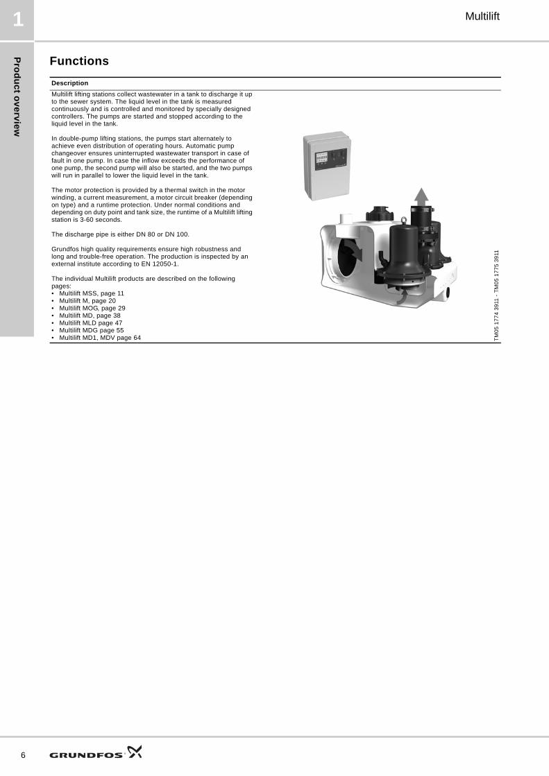
6. Multilift MOG
Multilift MOG is designed according to EN 12050-1 and approved by an external institute. It is supplied complete and ready to install.
Multilift MOG is equipped with a grinder pump (SEG) which is necessary when high discharge heads are required or long distances through a building must be overcome with small pipes.
Fig. 12 Multilift MOG
ApplicationsMultilift MOG is a compact and reliable lifting station with easy-to-operate controller for pumping of domestic wastewater (with faeces) in single-family houses, holiday cottages or light commercial applications.
Multilift MOG is typically used for
• basement installation below sewer level
• renovation or modernisation of existing buildings, e.g. developing basements with fitness room, sauna, bath, washroom, etc.
– direct connection of wall-hung or floor-standing toilets with horizontal outlet according to EN33/EN37.
Fig. 13 Example of installation of Multilift MOG in a pit in the building’s basement
Selection guide
Fig. 14 Maximum length of vertical and horizontal discharge pipes
Figure 14 shows the sizing guide with maximum length of vertical and horizontal pipes depending on the internal pipe diameter and the duty point. The non-return valve, an isolating valve and four bends have been taken into account. The limit of use is based on the self cleaning velocity of 0.7 m/s. Normal length of pipework in single-family houses or similar buildings is approx. 5-15 m.
TM
05
04
34
10
11T
M0
5 1
77
2 3
611
Max. pipe length
40 m 70 - - - DN 40 MOG.40
30 m 520 70 3 - DN 40 MOG.40
150 - - - DN 40 MOG.31
5 - - - DN 40 MOG.26
20 m 980 170 50 50 DN 40 MOG.40
580 80 7 10 DN 40 MOG.31
430 50 - - DN 40 MOG.26
130 - - - DN 40 MOG.15
- - - - DN 40 MOG.12
- - - - DN 40 MOG.09
15 m 1095 215 75 28 DN 40 MOG.40
785 135 35 1 DN 40 MOG.31
685 100 20 - DN 40 MOG.26
345 35 2 - DN 40 MOG.15
85 - - - DN 40 MOG.12
- - - DN 40 MOG.09
10 m 1390 270 100 42 DN 40 MOG.40
1040 180 60 17 DN 40 MOG.31
890 130 45 5 DN 40 MOG.26
540 80 18 - DN 40 MOG.15
340 35 - - DN 40 MOG.12
90 - - - DN 40 MOG.09
5 m 1600 320 145 67 DN 40 MOG.40
1250 235 110 52 DN 40 MOG.31
1100 205 75 29 DN 40 MOG.26
700 135 45 17 DN 40 MOG.15
400 85 20 5 DN 40 MOG.12
120 20 - - DN 40 MOG.09
Q [l/s] 0.9 2 3 4
Required min. flow for v = 0.7 m/s at DN 40
29

Mu
ltilift MO
G
30
Multilift6
Constructional features
Multilift MOG Description
TM
05
18
04
38
11 -
TM
05
20
55
43
11 -
TM
05
34
55
14
12
Pos. Controller
1Pre-assembled and ready to operate with all necessary presettings – only the inlet level needs to be set
2Controller with LCD display, interactive menu, multiple motor protection features and further safety options
3 Potential-free contact for common alarm (inside)
4
External alarm can be used e.g. to monitor the installation room or well around the lifting station with separate float switch outside the tank detect to groundwater intake, water pipe burst or other flooding accidents; no extra alarm device needed
5 Maintenance/service reminder (0, 3, 6 or 12 months)
6 Connection of PC Tool for further information and adjustments (inside)
7Quick and easy installation of the controller to the wall without the need of opening the cabinet
8 Holder for a quick guide
9 Phase inverter for easy changing of phases (only three-phase versions)
Pos. Level sensor
10No moving parts in pumped liquid. Blockage-free pressure tube, DN 100, connected via a pressure hose to piezoresistive pressure sensor in the controller.
11Screw cap serving as pressure tube fixation and tank inspection cover enabling easy maintenance of pressure tube and inspection of collecting tank
12Condensate trap prevents condensation in pressure hose incase of hot-water inflow
Pos. Collecting tank
13 Design and volume adapted to single-family house applications
14Possible to connect inlets from all directions and to connect floor-standing and wall-hung toilets; ideal for replacement and new installation
TM
05
03
32
09
11
15Unique, patented inlet disk, DN 100 (DN 150 as accessory), for stepless adjustment to inlet levels from 180 to 315 mm
16 Socket sealing for space saving installation
17Wastewater-resistant and odour-free, seamless collecting tank made of polyethylene (PE) with strong walls
18Sedimentation-free tank bottom with chamfers, leading the wastewater to the pump to reduce the need of cleaning the tank
19 Pressure-tight design up to 5 m water column according to EN 12050-1
20 Suitable for liquid temperature up to 50 °C
21 Easy handling during transportation and installation
Pos. Pump
TM
05
20
72
43
11
22Submersible stainless steel pump with highly reliable grinder system and adjustable, semi-open, radial impeller
23Clamp solution as a quick-release fastener makesit easy to separate motor from pump housing in case of service or maintenance.
24 Motor protection with built-in thermal switch
25Mechanical shaft seal in a cartridge for safe and quick replacement and a chamber filled with non-toxic oil to ensure reliable, long service life
26 Self-venting pump housing due to hydraulic design
14-16
13, 17-2122-25
2
1
4 5 7 8
3, 6
9
10
1211
26

Mu
ltil
ift
MO
G
Multilift 6
Product description
Features• Complete, pre-assembled and ready to install
• patented, turnable inlet disk enabling flexible connections from 180 to 315 mm inlet levels - ideal for new installations and replacements
• seven different inlet connections on all sides offer maximum installation flexibility
• six different motor sizes for perfect adjustment to the required draining performance
• easy-to-operate LC 221 controller with outstanding motor protection and additional safety and service functions. See LC 221 controller on page 79
• highly reliable grinder pump for pressurised operation
• reliable, blockage-free level detection with no direct contact to the pumped liquid
• Easy and smart maintenance and service features for pump, sensor tube, collecting tank and controller
See details on page 30.
Scope of deliveryGrundfos Multilift MOG lifting stations are supplied complete with collecting tank, one single- or three-phase grinder pump, level sensor, non-return valve and LC 221 controller. Both sensor and pump are connected to the controller with 10 m cable.
An accessories bag containing the following items is also included:
• 1 x installation and operating instructions
• 1 x quick guide
• 1 x oval discharge flange, 1 1/4"
• 1 x flexible hose, DN 70, and two clamps to connect venting pipe
• 2 x screw and expansion anchor for tank fixation
• 3 x screw and washer for fastening a pipe plug in the inlet disk, if required
• 1 x socket seal, DN 100
• 1 x socket seal, DN 50, for diaphragm pump connection or inlet, DN 50.
Type key
Collecting tankThe gas-, odour- and pressure-tight collecting tank is made of wastewater-resistant polyethylene (PE) and has all necessary ports for the connection of inlet pipes, discharge pipe, venting pipe and a manually operated diaphragm pump (accessory).
The main inlet on the rear side of the collecting tank is designed as a turnable disk, DN 100 (optional DN 150), adjustable to any inlet level between 180 and 315 mm.
Fig. 15 Main inlet with eccentric disk
The tank volume and effective volume (volume between start and stop) of the collecting tank appear from the following table:
Setting to the relevant inlet level must be made via the control panel of the controller. The factory-set inlet level is 250 mm above the floor.
Example M OG .22 .3 .4
Multilift lifting station
OG = one grinder pumpDG = two grinder pumps
Output power, P2 / 100 [W]
1 = single-phase motor3 = three-phase motor
2 = 2-pole motor4 = 4-pole motor
TM
05
03
51
09
11
Inlet level [mm] 180 250 315
Total tank volume [l] 93
Effective tank volume [l] 23 37 50
31

Mu
ltilift MO
G
32
Multilift6
PumpThe submersible cast iron pumps are equipped with a grinder system made of stainless steel. The semi-open, cast iron, radial impeller is used in applications requiring a relatively high pressure. The impeller can be adjusted to the pump housing to keep the optimum efficiency.
The pump has a mechanical shaft seal with an oil chamber, filled for life with non-toxic oil. The shaft seal is of the cartridge type, making it possible to replace the shaft seal in the field without using special tools. The clamp securing the motor to the pump housing is made of stainless steel and enables easy dismantling of the motor for service and maintenance.
Single-phase motors are protected by a thermal switch in the windings and run via a capacitor inside the controller cabinet. Three-phase motors are protected by a thermal switch in the windings and an additional thermal circuit breaker in the controller cabinet.
If the motor is overloaded, it will stop automatically. When it has cooled to normal operating temperature, it will restart automatically when automatic reset is set at the controller (factory setting).
The cable connection is a plug solution made of stainless steel.
In case of high inflow, the pump can start 60 times per hour. The start and stop sequence must correspond to intermittent duty (see Electrical data on page 34).
ControllerSee section LC 221 controller.

Mu
ltil
ift
MO
G
Multilift 6
Technical data
General data Material specification
Mechanical data
Parameter Value
Free passage 50 mm
Liquid temperatureMax. 40 °CFor short periods up to 60 °C (max. 5 minutes per hour)
Ambient temperature 0-40 °C
pH-value 4-10
Max. density of pump liquid 1,100 kg/m3
Enclosure class (lifting station and motor)
IP68
Enclosure class (controller) IP56
Insulation class (motor) F (155 °C)
Voltage (motor)1 x 230 V3 x 230 V3 x 400 V
Frequency (motor) 50 Hz
Potential-free contacts NO/NC, max. 250 VAC / 2 A
Voltage (sensor) 12 V
Signal output (sensor) 0-5 V
Power consumption (controller) 2 W
Number of starts per hour Max. 60
Sound pressure level 76 dB(A)
Dimensions (lifting station)See section Dimensional drawings
Dimensions (controller)Height = 390 mmWidth = 262 mmDepth = 142 mm
Component Material
Collecting tank Polyethylene (PE)
Pump housing Cast iron
Clamp Stainless steel
Impeller Cast iron
Shaft Stainless steel 1.4301
Shaft seal
Primary seal (0.9 - 1.5 kW): SiC/SiCSecondary seal (0.9 - 1.5 kW): Lip seal, NBRPrimary seal (2.6 - 4.0 kW): SiC/SiCSecondary seal (2.6 - 4.0 kW): Carbon/aluminium oxideOther components: NBR rubber, stainless steel
Control cabinet Acrylonitrile butadiene styrene (ABS)
Screws Stainless steel 1.4301
O-rings NBR rubber
Cable H07RN-F
Multilift Inlet level
[mm]
Tank volume
[l]
Effective tank volume [l]
Weight [kg]
Plug type
Cable length between plug and
controller [m]
Cable length between motor and controller
[m]
Product number
MOG.09.1.2
180 / 250 / 315 93 23 / 37 / 50
62 Schuko
1.5 10
97901124
MOG.09.3.2 62 CEE 3P+N+E, 16A 97901125
MOG.12.1.2 62 Schuko 97901126
MOG.12.3.2 62 CEE 3P+N+E, 16A 97901127
MOG.15.3.2 64 CEE 3P+E 16A 97901129
MOG.15.3.2 64 CEE 3P+N+E, 16A 97901128
MOG.26.3.2 85 CEE 3P+E 16A 97901131
MOG.26.3.2 85 CEE 3P+N+E, 16A 97901130
MOG.31.3.2 93 CEE 3P+E 16A 97901133
MOG.31.3.2 93 CEE 3P+N+E, 16A 97901132
MOG.40.3.2 93 CEE 3P+E 16A 97901135
MOG.40.3.2 93 CEE 3P+N+E, 16A 97901134
33

Mu
ltilift MO
G
34
Multilift6
Electrical data
* Tolerance: - 10 %/ 6 %
Performance curves
Multilift DutyVoltage
[V] *Power P1 / P2
[kW]I1/1 / Istart
[A]RPM
[min-1]Number of
polesStarting method
MOG.09.1.2
S3-35 %
1 x 230 V1.4 / 0.9
6.3 / 38 2890
2 DOL
MOG09.3.2 3 x 400 V 2.6 / 21 2860
MOG.12.1.2 1 x 230 V1.8 / 1.2
8.2 / 38 2820
MOG.12.3.2 3 x 400 V 3.1 / 21 2750
MOG.15.3.2 3 x 230 V2.3 / 1.5
6.6 / 36 2700
MOG.15.3.2 3 x 400 V 3.8 / 21 2700
MOG.26.3.2 3 x 230 V3.7 / 2.6
9.2 / 57 2870
MOG.26.3.2
S3-30 %
3 x 400 V 5.3 / 33 2870
MOG.31.3.2 3 x 230 V3.9 / 3.1
10.9 / 74 2900
MOG.31.3.2 3 x 400 V 6.3 / 43 2900
MOG.40.3.2 3 x 230 V5.2 / 4.0
14.2 / 74 2830
MOG.40.3.2 3 x 400 V 8.2 / 43 2830
TM
05
13
96
36
12
0.0 0.5 1.0 1.5 2.0 2.5 3.0 3.5 4.0 4.5 5.0 Q [l/s]
0
5
10
15
20
25
30
35
40
45
H[m]
0 2 4 6 8 10 12 14 16 Q [m³/h]
0
50
100
150
200
250
300
350
400
450
p[kPa] MOG/MDG
50 Hz ISO 9906 Annex A40.3
31.3
26.3
09.1
09.3
15.3
12.3
12.1
DN 32
DN 40
0.0 0.5 1.0 1.5 2.0 2.5 3.0 3.5 4.0 4.5 5.0 Q [l/s]
0
1
2
3
4
5
[kW]P1
40.3
31.326.3
09.109.3
12.112.3
15.3

Mu
ltil
ift
MO
G
Multilift 6
Dimensional drawings
TM
05
06
72
10
11
35
Mu
ltilift MO
G
36
Multilift6
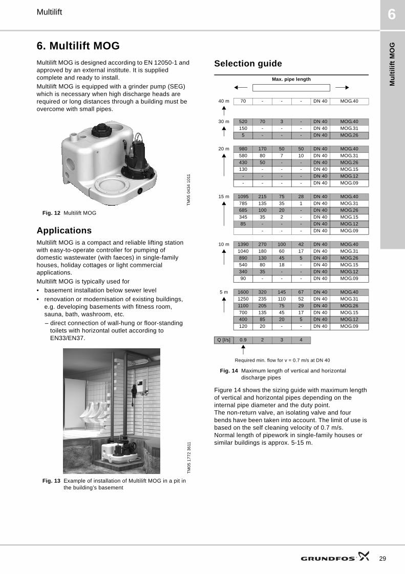
Accessories
Fig. 16 Accessories for Multilift MOG
TM
05
18
76
311
11
3
8
9
13
10
2
4
5
6
78
No. Figure Description Dimensions Product number
1 Isolating valve, PVC
DN 100Installation length: 130 mmHeight: 375 mmConnection piece: Ø110
96615831
2 Isolating valve, brassDN 32Installation length: 76 mmConnection: Rp 1 1/4"
00ID0918
3Flexible connection with clamps for additional connections and inlets
DN 32Length: 150 mmInternal Ø42
91071645
4 Manually operated diaphragm pumpInstallation length: 423 mmWidth: 215 mmConnection: Rp 1 1/2"
96003721
5 For wastewater pump, e.g. Unilift CC and KP, please see data booklet for the pump or WebCAPS.
6 Non-return flap valve, compositeLength: 90 mmHeight: 90 mmConnection: Rp 1 1/4"
96005308
7
Socket seal for additional standard inlet
DN 100, internal ∅110 97726942
Socket seal for additional inlet (vertical inlet on top)
DN 150, internal Ø160 96636544
8Turnable inlet disk with socket seal for adjustable inlet level
DN 150Internal ∅160
98079681

Mu
ltil
ift
MO
G
Multilift 6
9 Socket seal for additional inletDN 50Internal ∅48-50
98079669
10Battery buffer for alarm in case of mains failure (battery is not included). Replace the battery once a year
Use a commercially available 9.6 V battery
11 Signal lamp for wall mounting 1 x 230 V, 50 Hz 91077209
12 Signal horn
Indoors, 1 x 230 V, 50 Hz 62500021
Outdoors, 1 x 230 V, 50 Hz 62500022
13 Level switch type SAS Cable length 5 m, 250 V 00ID7805
14 External main switch for supply cable Up to 25 A 96002511
15
1 1/2" complete, pre-assembled discharge pipework incl.:- 1 x flexible connecting piece with 2 clamps, DN 40 (not shown, see Pos. 6a)- 1 x hose nozzle, Rp 1 1/2 / DN 40- 1 x isolating valve (ball), R 1 1/2- 2 x double nipple, Rp 1 1/2- 1 x non-return ball valve, R 1 1/2- 1 x bend, 90 ° Rp 1 1/2 / R 1 1/2(Pipework can be set up in 1 1/4" / DN 32 locally)
98085356
16
Non-return ball valve, Rp 1 1/4, made of cast iron with epoxy coating, to be mounted on installation site
Length: 140 mmWidth: 83 mm
96116550
Non-return ball valve, Rp 1 1/2, made of cast iron with epoxy coating
Length: 140 mmWidth: 83 mm
91076761
17 Venting valve (with filter) DN 70/80/100 98059596
18 Filter kit for venting valve DN 70/80/100 98059594
19 Wall installation box for venting valve 204 x 204 x 130 mm 98059598
20 PC Tool link USB 96705378
No. Figure Description Dimensions Product number
37

Mu
ltilift MD
38
Multilift7
7. Multilift MD
Multilift MD is designed according to EN 12050-1 and approved by an external institute. It is supplied complete and ready to install with butterfly non-return valve.
Fig. 17 Multilift MD
ApplicationsMultilift MD is a compact and reliable lifting station with easy-to-operate controller for pumping of domestic wastewater (with faeces) in multi-family houses as well as in public and commercial buildings, such as offices, schools, hotels and restaurants.
Multilift MD is typically used for
• basement installation below sewer level
• renovation or modernisation of existing buildings, e.g. developing basements with fitness room, sauna, bath, washroom, etc.
– direct connection of wall-hung and floor-standing toilets with horizontal outlet according to EN33/EN37.
Fig. 18 Example of application installation of Multilift MD in a pit in the building’s basement
Selection guide
Fig. 19 Maximum length of vertical and horizontal discharge pipes
Figure 19 shows the sizing guide with maximum length of vertical and horizontal pipes depending on the internal pipe diameter and the duty point. The non-return valve, an isolating valve and four bends have been taken into account. The limit of use is based on the self cleaning velocity of 0.7 m/s.
TM
05
04
30
10
11T
M0
5 1
77
2 3
611
Max. pipe length
15 m 85 - - - - DN 100 MD.38
13 m 385 200 42 - - - - DN 100 MD.38
115 - - - - - - DN 100 MD.32
11 m 680 415 180 94 30 - - DN 100 MD.38
415 210 34 - - - - DN 100 MD.32
9 m 980 630 330 209 120 13 - DN 100 MD.38
710 425 178 88 20 - - DN 100 MD.32
175 60 - - - - - DN 100 MD.24
7 m 1280 850 475 325 215 75 - DN 100 MD.38
1010 640 325 198 115 - - DN 100 MD.32
475 275 56 - - - - DN 100 MD.24
220 110 49 - - - - DN 100 MD.22
5 m 1575 1075 620 440 3100 140 40 DN 100 MD.38
1310 860 470 320 205 70 - DN 100 MD.32
770 490 208 100 28 - - DN 100 MD.24
520 3300 194 135 90 35 5 DN 100 MD.22
265 155 63 30 - - - DN 100 MD.15
160 70 - - - - - DN 100 MD.12
3 m 1875 1280 765 495 405 200 92 DN 100 MD.38
1605 1075 615 435 300 135 42 DN 100 MD.32
1070 705 345 215 122 15 - DN 100 MD.24
815 545 338 250 183 105 57 DN 100 MD.22
565 370 208 145 98 30 - DN 100 MD.15
460 285 143 88 51 - - DN 100 MD.12
2 m 2025 1390 837 610 450 235 118 DN 100 MD.38
1755 1180 685 490 348 170 68 DN 100 MD.32
1220 815 418 275 168 50 - DN 100 MD.24
965 650 410 307 230 140 83 DN 100 MD.22
710 480 280 204 1145 65 18 DN 100 MD.15
605 395 215 145 98 30 - DN 100 MD.12
Q [l/s]
5/5 6.5 8 9 10 12 14
Required min. flow for v = 0.7 m/s at DN 100

Mu
ltil
ift
MD
Multilift 7
Constructional features
Multilift MD Description
Pos. Controller
1Pre-assembled and ready to operate with all necessary presettings – only the inlet level needs to be set
2Controller with LCD display, interactive menu, multiple motor protection features and further safety options
3 Potential-free contact for common alarm (inside)
4
External alarm can be used e.g. to monitor the installation room or well around the lifting station with separate float switch outside the tank to detect groundwater intake, water pipe burst or other flooding accidents; no extra alarm device needed
5 Maintenance/service reminder (0, 3, 6 or 12 months)
6 Connection of PC Tool for further information and adjustments (inside)
7Quick and easy installation of the controller to the wall without the need of opening the cabinet
8 Holder for a quick guide
9 Phase inverter for easy changing of phases (only three-phase versions)
Pos. Level sensor
10No moving parts in pumped liquid. Blockage-free pressure tube, DN 100, connected via a pressure hose to piezoresistive pressure sensor in the controller.
11Screw cap for pressure tube fixation and tank inspection cover enabling easy maintenance of pressure tube and inspection of collecting tank
12Condensate trap prevents condensation in pressure hose in case of hot-water inflow
Pos. Collecting tank
13Design and volume adapted to multi-family house and commercial applications
14Possible to connect inlets from all directions and to connect floor-standing and wall-hung toilets; ideal for replacement and new installation
15Unique, patented inlet disk, DN 100 (DN 150 as accessory), for stepless adjustment to inlet levels from 180 to 315 mm
16 Socket sealing for space saving installation
17Wastewater-resistant and odour-free, seamless collecting tank made of polyethylene (PE) with strong walls
18Sedimentation-free tank bottom with chamfers, leading the wastewater to the pump to reduce the need of cleaning the tank
19 Pressure tight design up to 5 m water column according to EN 12050-1
20 Suitable for liquid temperature up to 50 °C
21 Easy handling during transportation and installation
Pos. Pump
22Six motor sizes adapted to all application needs, up to 21 m discharge head and 50 m3 discharge flow
23Vortex impeller with large free passage for trouble-free operation and unchanged performance throughout the entire life of the pump
24 Motor protection with built-in thermal switch
25Highly reliable motor design with up to 60 starts per hour for handling peak inflow conditions
26Tripple shaft seal and a chamber filled with non-toxic oil to ensure reliable, long service life
27 Self-venting pump housing due to hydraulic design
Pos. Non-return valve DN 80
28 Designed and approved according to EN 12050-4
29Compact design with large and well accessible inspection cover for taking out foreign bodies, if necessary
30 Lifting device to drain discharge pipe in case of service or maintenance
31 Smooth and silent flap valve
Pos. Discharge
32 Flexible and sound absorbing discharge connection
14-16
13, 17-2122-27
2
1
4 5 7 8
3, 6
9
28
30
29
31
12
11
10
32
39

Mu
ltilift MD
40
Multilift7
Product description
Features• Complete, pre-assembled and ready to install
• patented, turnable inlet disk enabling flexible connections from 180 to 315 mm inlet levels - ideal for new installations and replacements
• seven different inlet connections on all sides offer maximum installation flexibility
• six different motor sizes for perfect adjustment to the required draining performance
• easy-to-operate LC 221 controller with outstanding motor protection and additional safety and service functions. See LC 221 controller on page 79
• reliable, blockage-free level detection with no direct contact to the pumped liquid
• one back-up pump for high operating safety
• easy and smart maintenance and service features for sensor tube, collecting tank and controller.
See details on page 39.
Scope of deliveryGrundfos Multilift MD lifting stations are supplied complete with collecting tank, two single- or three-phase pumps, level sensor, butterfly non-return valve and LC 221 controller. Both sensor and pumps are connected to the controller with 4 or 10 m cable and hose.
An accessories bag containing the following items is also included:
• 1 x installation and operating instructions
• 1 x Quick guide for controller menu
• 1 x discharge adapter flange, DN 80, with connection piece, DN 100 (outer diameter, 110 mm)
• 1 x flexible hose, DN 100, and two clamps to connect the discharge pipe
• 1 x flexible hose, DN 70, and two clamps to connect the venting pipe
• 2 x screw and expansion anchor for tank fixation
• 3 x screw and washer for fastening a pipe plug in the inlet disk, if required
• 1 x socket seal, DN 100
• 1 x socket seal, DN 50, for diaphragm pump connection or inlet, DN 50
• 1 x gasket kit, DN 80, 8 bolts M16 x 65, nuts and washers (galvanized).
Type key
Collecting tankThe gas-, odour- and pressure-tight collecting tank is made of wastewater-resistant polyethylene (PE) and has all necessary ports for the connection of inlet pipes, discharge pipe, venting pipe and a manually operated diaphragm pump (accessory).
The main inlet on the rear side of the collecting tank is designed as a turnable disk, DN 100 (optional DN 150), adjustable to any inlet level between 180 and 315 mm.
Fig. 20 Main inlet with eccentric disk
The tank volume and effective volume (volume between start and stop) of the collecting tank appear from the following table:
Setting to the relevant inlet level must be made via the control panel of the controller. The factory-set inlet level is 250 mm above the floor.
Example M D .22 .3 .4
Multilift lifting station
[ ] = normal-size tank
D = 2 pumps
Output power, P2 / 100 [W]
1 = single-phase motor 3 = three-phase motor
2 = 2-pole motor4 = 4-pole motor
TM
05
03
51
09
11
Inlet level [mm] 180 250 315
Total tank volume [l] 130
Effective tank volume [l] 49 69 86

Mu
ltil
ift
MD
Multilift 7
PumpThe composite impeller of the submersible cast iron pump is designed as a free-flow, vortex impeller, ensuring almost unchanged performance throughout the entire life of the pump. The pump has three shaft seals with an oil chamber filled for life with non-toxic oil.
Single-phase motors are protected by a thermal switch in the windings and run via a capacitor inside the controller cabinet. Three-phase motors are protected by a thermal switch in the windings and an additional thermal circuit breaker in the controller cabinet.
If the motor is overloaded, it will stop automatically. When it has cooled to normal operating temperature, it will restart automatically when automatic reset is set at the controller (factory setting).
Incase of high inflow, the pump can start 60 times per hour. The start and stop sequence must correspond to intermittent duty (see Electrical data on page 42).
ControllerSee section LC 221 controller.
41

Mu
ltilift MD
42
Multilift7
Technical data
General data
Material specification
Mechanical data
Electrical data
* Tolerance: - 10 %/ 6 %
Parameter Value
Free passage 50 mm
Liquid temperatureMax. 40 °CFor short periods up to 60 °C (max. 5 minutes per hour)
Ambient temperature 0-40 °C
pH-value 4-10
Max. density of pump liquid 1,100 kg/m3
Enclosure class (lifting station and motor)
IP68(2 m water column for 7 days)
Enclosure class (controller) IP56
Insulation class (motor) F (155 °C)
Voltage (motor)1 x 230 V3 x 230 V3 x 400 V
Frequency (motor) 50 Hz
Potential-free contacts NO/NC, max. 250 VAC / 2 A
Voltage (sensor) 12 V
Signal output (sensor) 0-5 V
Power consumption (controller) 2 W
Number of starts per hour Max. 60
Sound pressure level < 70 dB(A)
Dimensions (lifting station)See section Dimensional drawings
Dimensions (controller)Height = 390 mmWidth = 262 mmDepth = 142 mm
Component Material
Collecting tank Polyethylene (PE)
Pump housing Cast iron
Impeller Luranyl
Shaft Stainless steel 1.4301
Control cabinet Acrylonitrile butadiene styrene (ABS)
Screws Stainless steel 1.4301
O-rings NBR rubber
Cable Neoprene
Parameter Value
Multilift Inlet level
[mm]
Tank volume
[l]
Effective tank volume [l]
Weight [kg]
Plug type
Cable length between plug and
controller [m]
Cable length between motor and controller
[m]
Product number
MD.12.1.4
180/250/315 139 49/69/86
119 CEE 2P+E 32A
1.5 4
97901084
MD.12.3.4 119 CEE 3P+N+E, 16A 97901085
MD.15.1.4 119 CEE 2P+E 32A 97901086
MD.15.3.4 119 CEE 3P+N+E, 16A 97901087
MD.22.3.4 121 CEE 3P+E 32A 97901089
MD.22.3.4 121 CEE 3P+N+E, 16A 97901088
MD.24.3.2 126 CEE 3P+E 32A 97901091
MD.24.3.2 126 CEE 3P+N+E, 16A 97901090
MD.32.3.2 126 CEE 3P+E 32A 97901093
MD.32.3.2 126 CEE 3P+N+E, 16A 97901092
MD.38.3.2 126 CEE 3P+E 32A 97901095
MD.38.3.2 126 CEE 3P+N+E, 16A 97901094
MD.12.1.4
180/250/315 130 49/69/86
119 CEE 2P+E 32A
1.5 10
97901096
MD.12.3.4 119 CEE 3P+N+E, 16A 97901097
MD.15.1.4 119 CEE 2P+E 32A 97901098
MD.15.3.4 119 CEE 3P+N+E, 16A 97901099
MD.22.3.4 121 CEE 3P+N+E, 16A 97901100
MD.24.3.2 126 CEE 3P+N+E, 16A 97901101
MD.32.3.2 126 CEE 3P+N+E, 16A 97901102
MD.38.3.2 126 CEE 3P+N+E, 16A 97901103
Multilift DutyVoltage
[V]*Power P1 / P2
[kW]I1/1 / Istart
[A]RPM [min-1]
Number of poles
Starting method
MD.12.1.4
S3-40 %, 1 min.
1 x 230 V 1.9 / 1.4 9 / 391430 4
DOL
MD.12.3.4 3 x 400 V 1.8 / 1.5 3.6 / 19
MD.15.1.4 1 x 230 V 2.2 / 1.6 10.1 / 391410 4
MD.15.3.4 3 x 400 V 2.1 / 1.7 4.0 / 19
MD.22.3.4
S3-50 %, 1 min.
3 x 230 V3.0 / 2.5
10.2 / 51.51430 4
MD.22.3.4 3 x 400 V 5.5 / 29.7
MD.24.3.2 3 x 230 V3.1 / 2.7
9.7 / 88.72920 2
MD.24.3.2 3 x 400 V 5.5 / 39
MD.32.3.2 3 x 230 V4.0 / 3.4
88.72920 2
MD.32.3.2 3 x 400 V 6.7 / 39
MD.38.3.2S3-40 %, 1 min.
3 x 230 V4.6 / 3.8
13 / 88.72880 2
MD.38.3.2 3 x 400 V 7.5 / 39

Mu
ltil
ift
MD
Multilift 7
Performance curves
TM
05
12
87
26
11
0 1 2 3 4 5 6 7 8 9 10 11 12 13 14 15 16 Q [l/s]0
1
2
3
4
5
6
7
8
9
10
11
12
13
14
15
16
17
18
19
20
21
H[m]
0 5 10 15 20 25 30 35 40 45 50 55 Q [m³/h]
0
20
40
60
80
100
120
140
160
180
200
p[kPa]
Multilift
50 HzISO 9906 Annex A
MD/MLD
12.1
12.3
15.1
15.3
22
24
32
38
Min. flow rate DN 80
Min. flow rate DN 100
0 1 2 3 4 5 6 7 8 9 10 11 12 13 14 15 16 Q [l/s]0.0
0.5
1.0
1.5
2.0
2.5
3.0
3.5
4.0
4.5
P1[kW]
12.312.1
15.315.1
2224
32
38
MD
43

Mu
ltilift MD
44
Multilift7
Dimensional drawings
TM
05
04
42
10
11

Mu
ltil
ift
MD
Multilift 7
Accessories
Fig. 21 Accessories for Multilift MD
TM
05
20
15
42
11
5
2
3
1
6
11
4
7
810
9
12
15
No. Figure Description Dimensions Product number
1 Isolating valve, PVC
DN 100Installation length: 130 mmHeight: 375 mmConnection piece: Ø110
96615831
2 Isolating valve, epoxy-coated cast iron
DN 80Installation length: 180 mmHeight: 300 mmConnection: flange PN 10
96002011
3 Isolating valve, brassDN 32Length: 76 mmConnection: Rp 1 1/4"
00ID0918
4Flexible connection with clamps for additional connections and inlets
DN 32Length: 150 mmInternal Ø42
91071645
5 Manually operated diaphragm pumpInstallation length: 423 mmWidth: 215 mmConnection: Rp 1 1/2"
96003721
6 For wastewater pump, e.g. Unilift CC and KP, please see data booklet for the pump or WebCAPS.
7 Non-return flap valve, compositeLength: 90 mmHeight: 90 mmConnection: Rp 1 1/4"
96005308
45

Mu
ltilift MD
46
Multilift7
8
Socket seal for additional standard inlet
DN 100Internal ∅110
97726942
Socket seal for additional inlet (vertical inlet on top)
DN 150, internal Ø160 96636544
9Turnable inlet disk with socket seal for adjustable inlet level
DN 150 Internal ∅160
98079681
10 Socket seal for additional inletDN 50Internal ∅48-50
98079669
11Bolts, nuts, 8 of each, (galvanised) Gasket
16 x 65 mmDN 80
96001999
12Battery buffer for alarm in case of mains failure (battery is not included).Replace the battery once a year
Use a commercially available 9.6 V battery
13 Signal lamp for wall mounting 1 x 230 V, 50 Hz 91077209
14 Signal horn
Indoors, 1 x 230 V, 50 Hz 62500021
Outdoors, 1 x 230 V, 50 Hz 62500022
15 Level switch type SAS Cable length 5 m, 250 V 00ID7805
16 External main switch for supply cable Up to 25 A 96002511
17 Venting valve (with filter) DN 70/80/100 98059596
18 Filter kit for venting valve DN 70/80/100 98059594
19 Wall installation box for venting valve 204 x 204 x 130 mm 98059598
20 PC Tool link USB 96705378
No. Figure Description Dimensions Product number

Mu
ltil
ift
ML
D
Multilift 8
8. Multilift MLD
Multilift MLD is designed according to EN 12050-1 and approved by an external institute. It is supplied complete and ready to install with butterfly non-return valve.
Fig. 22 Multilift MLD
ApplicationsMultilift MLD is a compact and reliable lifting station with easy-to-operate controller for pumping of domestic wastewater (with faeces) in multi-family houses as well as in public and commercial buildings, such as offices, schools, hotels and restaurants.
Multilift MLD is typically used for
• basement installation below sewer level
• renovation or modernisation of existing buildings, e.g. developing basements with fitness room, sauna, bath, washroom, etc.
Fig. 23 Example of installation of Multilift MLD in a pit in the building’s basement
Selection guide
Fig. 24 Maximum length of vertical and horizontal discharge pipes
Figure 24 shows the sizing guide with maximum length of vertical and horizontal pipes depending on the internal pipe diameter and the duty point. The non-return valve, an isolating valve and four bends have been taken into account. The limit of use is based on the self cleaning velocity of 0.7 m/s.
TM
05
04
32
10
11T
M0
5 1
77
2 3
611
Max. pipe length
15 m 85 - - - - DN 100 M.38
13 m 385 200 42 - - - - DN 100 M.38
115 - - - - - - DN 100 M.32
11 m 680 415 180 94 30 - - DN 100 M.38
415 210 34 - - - - DN 100 M.32
9 m 980 630 330 209 120 13 - DN 100 M.38
710 425 178 88 20 - - DN 100 M.32
175 60 - - - - - DN 100 M.24
7 m 1280 850 475 325 215 75 - DN 100 M.38
1010 640 325 198 115 - - DN 100 M.32
475 275 56 - - - - DN 100 M.24
220 110 49 - - - - DN 100 M.22
5 m 1575 1075 620 440 3100 140 40 DN 100 M.38
1310 860 470 320 205 70 - DN 100 M.32
770 490 208 100 28 - - DN 100 M.24
520 3300 194 135 90 35 5 DN 100 M.22
265 155 63 30 - - - DN 100 M.15
160 70 - - - - - DN 100 M.12
3 m 1875 1280 765 495 405 200 92 DN 100 M.38
1605 1075 615 435 300 135 42 DN 100 M.32
1070 705 345 215 122 15 - DN 100 M.24
815 545 338 250 183 105 57 DN 100 M.22
565 370 208 145 98 30 - DN 100 M.15
460 285 143 88 51 - - DN 100 M.12
2 m 2025 1390 837 610 450 235 118 DN 100 M.38
1755 1180 685 490 348 170 68 DN 100 M.32
1220 815 418 275 168 50 - DN 100 M.24
965 650 410 307 230 140 83 DN 100 M.22
710 480 280 204 1145 65 18 DN 100 M.15
605 395 215 145 98 30 - DN 100 M.12
Q [l/s]
5/5 6.5 8 9 10 12 14
Required min. flow for v = 0.7 m/s at DN 100
47

Mu
ltilift ML
D
48
Multilift8
Constructional features
Multilift MLD Description
TM
05
20
55
43
11 -
TM
05
34
55
14
12
- T
M0
5 1
77
4 3
711
Pos. Controller
1Pre-assembled and ready to operate with all necessary presettings – only the inlet level needs to be set
2Controller with LCD display, interactive menu, multiple motor protection features and further safety options
3 Potential-free contact for common alarm (inside)
4
External alarm can be used e.g. to monitor the installation room or well around the lifting station with separate float switch outside the tank to detect groundwater intake, water pipe burst or other flooding accidents; no extra alarm device needed
5 Maintenance/service reminder (0, 3, 6 or 12 months)
6 Connection of PC Tool for further information and adjustments (inside)
7Quick and easy installation of the controller to the wall without the need of opening the cabinet
8 Holder for a quick guide
9 Phase inverter for easy changing of phases (only three-phase versions)
Pos. Level sensor
10No moving parts in pumped liquid. Blockage-free pressure tube, DN 100, connected via a pressure hose to piezoresistive pressure sensor in the controller
11Screw cap for pressure tube fixation and tank inspection cover, enabling easy maintenance of pressure tube and inspection of collecting tank
12Condensate trap prevents condensation in pressure hose in case of hot-water inflow
Pos. Collecting tank
TM
05
03
32
09
11
13Design and volume adapted to multi-family house and commercial applications
14Possible to connect inlet DN 150 from three horizontal directions and vertically
15 High effective tank volume of 190 litres
16Wastewater-resistant and odour-free, seamless collecting tank made of polyethylene (PE) with strong walls
17Sedimentation-free tank bottom with chamfers, leading the wastewater to the pump to reduce the need of cleaning the tank
18 Pressure tight design up to 5 m water column according to EN 12050-1
19 Suitable for liquid temperature up to 50 °C
20 Easy handling during transportation and installation
Pos. Pump
TM
05
20
73
43
11
21Six motor sizes adapted to all application needs, up to 21 m discharge head and 50 m3 discharge flow.
22Vortex impeller with large free passage for trouble-free operation and unchanged performance throughout the entire life of the pump
23 Motor protection with built-in thermal switch
24Highly reliable motor design with up to 60 starts per hour for handling peak inflow conditions
25Tripple shaft seal and a chamber filled with non-toxic oil to ensure reliable, long service life
26 Self-venting pump housing due to hydraulic design
Pos. Non-return valve
27 Designed and approved according to EN 12050-4
TM
05
15
30
29
11
28Compact design with large and well accessible inspection cover for taking out foreign bodies if necessary
29 Lifting device to drain discharge pipe in case of service or maintenance
30 Smooth and silent flap valve
Pos. Discharge
31 Flexible and sound absorbing discharge connection
14, 15
13, 16-2021-26
2
1
4 5 7 8
9
12
10
11
27
2829
30
3, 6
31

Mu
ltil
ift
ML
D
Multilift 8
Product description
Features • Complete, pre-assembled and ready to install
• high effective volume
• eight different motor sizes for perfect adjustment to the required draining performance
• easy-to-operate LC 221 controller with outstanding motor protection and additional safety and service functions. See LC 221 controller on page 79
• reliable blockage-free level detection with no direct contact to the pumped liquid
• one backup pump for high operating safety
• easy and smart maintenance and service features for sensor tube, collecting tank and controller.
See details on page 48.
Scope of deliveryGrundfos Multilift MLD lifting stations are supplied complete with collecting tank, two single- or three-phase pumps, level sensor, butterfly non-return valve and LC 221 controller. Both sensor and pump are connected to the controller with 4 or 10 m cable and hose.
An accessories bag containing the following items is also included:
• 1 x installation and operating instructions
• 1 x Quick guide for controller menu
• 1 x discharge adapter flange, DN 80, with connection piece, DN 100 (outer diameter, 110 mm)
• 1 x flexible hose, DN 100, and two clamps to connect discharge pipe
• 1 x flexible hose, DN 70, and two clamps to connect venting pipe
• 4 x screw and expansion anchor for tank fixation
• 1 x socket seal, DN 150
• 1 x flexible hose connection with two clamps, DN 50, for diaphragm pump connection or inlet, DN 50
• 1 x gasket kit, DN 80, 8 bolts M16 x 65, nuts and washers (galvanized).
Type key
Collecting tankThe gas-, odour- and pressure-tight collecting tank is made of wastewater resistant polyethylene (PE) and has all necessary ports for the connection of inlet pipes, discharge pipe, venting pipe and a manually operated diaphragm pump (accessory).
The tank volume and effective volume (volume between start and stop) of the collecting tank appear from the following table:
Setting to the relevant inlet level must be made via the control panel of the controller. The factory-set inlet level is 250 mm above the floor.
PumpThe composite impeller of the pump is designed as a free-flow, vortex impeller, ensuring almost unchanged performance throughout the entire life of the pump. The pump has three shaft seals with an oil chamber filled for life with non-toxic oil.
Single-phase motors are protected by a thermal switch in the windings and run via a capacitor inside the controller cabinet. Three-phase motors are protected by a thermal switch in the windings and an additional thermal circuit breaker in the controller cabinet.
If the motor is overloaded, it will stop automatically. When it has cooled to normal operating temperature, it will restart automatically when automatic reset is set at the controller (factory setting).
In case of high inflow, the pump can start 60 times per hour. The start and stop sequence must correspond to intermittent duty (see Electrical data on page 50).
ControllerSee section LC 221 controller.
Example M L D .22 .3 .4
Multilift lifting station
L = large tank
D = 2 pumps
Output power, P2 / 100 [W]
1 = single-phase motor 3 = three-phase motor
2 = 2-pole motor4 = 4-pole motor
Inlet level [mm] 560
Total tank volume [l] 270
Effective tank volume [l] 190
49

Mu
ltilift ML
D
50
Multilift8
Technical data
General data
Material specification
Mechanical data and order data
Electrical data
* Tolerance: - 10 %/ 6 %
Parameter Value
Free passage 50 mm
Liquid temperatureMax. 40 °CFor short periods up to 60 °C (max. 5 minutes per hour)
Ambient temperature 0-40 °C
pH-value 4-10
Max. density of pump liquid 1,100 kg/m3
Enclosure class (lifting station and motor)
IP68(2 m water column for 7 days)
Enclosure class (controller) IP56
Insulation class (motor) F (155 °C)
Voltage (motor)1 x 230 V3 x 230 V3 x 400 V
Frequency (motor) 50 Hz
Potential-free contacts NO/NC, max. 250 VAC / 2 A
Voltage (sensor) 12 V
Signal output (sensor) 0-5 V
Power consumption (controller) 2 W
Number of starts per hour Max. 60
Sound pressure level < 70 dB(A)
Dimensions (lifting station)See section Dimensional drawings
Dimensions (controller)Height = 390 mmWidth = 262 mmDepth = 142 mm
Component Material
Collecting tank Polyethylene (PE)
Pump housing Cast iron
Impeller Luranyl
Shaft Stainless steel 1.4301
Control cabinet Acrylonitrile butadiene styrene (ABS)
Screws Stainless steel 1.4301
O-rings NBR rubber
Cable Neoprene
Parameter Value
Multilift Inlet level
[mm]
Tank volume
[l]
Effective tank volume [l]
Weight [kg]
Plug type
Cable length between plug and
controller [m]
Cable length between motor and controller
[m]
Product number
MLD.12.1.4
560 270 190
130 CEE 2P+E 32A
1.5 4
97901104
MLD.12.3.4 130 CEE 3P+N+E, 16A 97901105
MLD.15.1.4 130 CEE 2P+E 32A 97901106
MLD.15.3.4 130 CEE 3P+N+E, 16A 97901107
MLD.22.3.4 132 CEE 3P+E 32A 97901109
MLD.22.3.4 132 CEE 3P+N+E, 16A 97901108
MLD.24.3.2 136 CEE 3P+E 32A 97901111
MLD.24.3.2 136 CEE 3P+N+E, 16A 97901110
MLD.32.3.2 136 CEE 3P+E 32A 97901113
MLD.32.3.2 136 CEE 3P+N+E, 16A 97901112
MLD.38.3.2 136 CEE 3P+E 32A 97901115
MLD.38.3.2 136 CEE 3P+N+E, 16A 97901114
MLD.12.1.4
560 270 190
130 CEE 2P+E 32A
1.5 10
97901116
MLD.12.3.4 130 CEE 3P+N+E, 16A 97901117
MLD.15.1.4 130 CEE 2P+E 32A 97901118
MLD.15.3.4 130 CEE 3P+N+E, 16A 97901119
MLD.22.3.4 132 CEE 3P+N+E, 16A 97901120
MLD.24.3.2 136 CEE 3P+N+E, 16A 97901121
MLD.32.3.2 136 CEE 3P+N+E, 16A 97901122
MLD.38.3.2 136 CEE 3P+N+E, 16A 97901123
Multilift DutyVoltage
[V]* Power P1 / P2
[kW]I1/1 / Istart
[A]RPM
[min-1]Number of
polesStarting method
MLD.12.1.4
S3-40 %, 1 min.
1 x 23 0 V 1.9 / 1.4 9 / 391430 4
DOL
MLD.12.3.4 3 x 400 V 1.8 / 1.5 3.6 / 19
MLD.15.1.4 1 x 230 V 2.2 / 1.6 10.1 / 391410 4
MLD.15.3.4 3 x 400 V 2.1 / 1.7 4.0 / 19
MLD.22.3.4
S3-50 %, 1 min.
3 x 230 V3.0 / 2.5
10.2 / 51.51430 4
MLD.22.3.4 3 x 400 V 5.5 / 29.7
MLD.24.3.2 3 x 230 V3.1 / 2.7
9.7 / 88.72920 2
MLD.24.3.2 3 x 400 V 5.5 / 39
MLD.32.3.2 3 x 230 V4.0 / 3.4
88.72920 2
MLD.32.3.2 3 x 400 V 6.7 / 39
MLD.38.3.2S3-40 %, 1 min.
3 x 230 V4.6 / 3.8
13 / 88.72880 2
MLD.38.3.2 3 x 400 V 7.5 / 39

Mu
ltil
ift
ML
D
Multilift 8
Performance curves
TM
05
12
87
26
11
0 1 2 3 4 5 6 7 8 9 10 11 12 13 14 15 16 Q [l/s]0
1
2
3
4
5
6
7
8
9
10
11
12
13
14
15
16
17
18
19
20
21
H[m]
0 5 10 15 20 25 30 35 40 45 50 55 Q [m³/h]
0
20
40
60
80
100
120
140
160
180
200
p[kPa]
Multilift
50 HzISO 9906 Annex A
MD/MLD
12.1
12.3
15.1
15.3
22
24
32
38
Min. flow rate DN 80
Min. flow rate DN 100
0 1 2 3 4 5 6 7 8 9 10 11 12 13 14 15 16 Q [l/s]0.0
0.5
1.0
1.5
2.0
2.5
3.0
3.5
4.0
4.5
P1[kW]
12.312.1
15.315.1
2224
32
38
MLD
51

Mu
ltilift ML
D
52
Multilift8
Dimensional drawings
TM
05
04
42
10
11

Mu
ltil
ift
ML
D
Multilift 8
Accessories
Fig. 25 Accessories for Multilift MLD
TM
05
20
34
42
11
3
6 5
84
1
2
3
4
5
6
9
10
13
7
No. Figure Description Dimensions Product number
1 Isolating valve, PVC
DN 150Installation length: 227 mmHeight: 496 mmConnection piece: Ø160
96697920
2 Isolating valve, epoxy-coated cast iron
DN 80Installation length: 180 mmHeight: 300 mmConnection: flange PN 10
96002011
3 Isolating valve, brassDN 32Length: 76 mmConnection: Rp 1 1/4"
00ID0918
4Flexible connection with clamps for additional connections and inlets
DN 32Length: 150 mm Internal-Ø42
91071645
5 Manually operated diaphragm pumpInstallation length: 423 mmWidth: 215 mmConnection: Rp 1 1/2"
96003721
6 For wastewater pump, e.g. Unilift CC and KP, please see data booklet for the pump or WebCAPS.
7 Non-return flap valve, compositeLength: 90 mmHeight: 90 mmConnection: Rp 1 1/4"
96005308
8 Socket seal for additional inletDN 50 Internal ∅48-50
98079669
9Bolts, nuts, 8 of each galvanised Gasket
16 x 65 mmDN 80
96001999
53

Mu
ltilift ML
D
54
Multilift8
10
Battery buffer for alarm in case of mains failure (battery is not included) Use a commercially available 9.6 V battery
Replace the battery once a year.
11 Signal lamp for wall mounting 1 x 230 V, 50 Hz 91077209
12 Signal horn
Indoors, 1 x 230 V, 50 Hz 62500021
Outdoors, 1 x 230 V, 50 Hz 62500022
13 Level switch type SAS Cable length 5 m, 250 V 00ID7805
14 External main switch for supply cable Up to 25 A 96002511
15 Venting valve (with filter) DN 70/80/100 98059596
16 Filter kit for venting valve DN 70/80/100 98059594
17 Wall installation box for venting valve 204 x 204 x 130 mm 98059598
18 PC Tool link USB 96705378
No. Figure Description Dimensions Product number

Mu
ltil
ift
MD
G
Multilift 9
9. Multilift MDG
Multilift MOG is designed according to EN 12050-1 and approved by an external institute. It is supplied complete and ready to install.
Multilift MDG is equipped with two grinder pumps (SEG) which is necessary when high discharge heads are required or long distances through a building must be overcome with small pipes.
Fig. 26 Multilift MDG
ApplicationsMultilift MDG is a compact and reliable lifting station with easy-to-operate controller for pumping of domestic wastewater (with faeces) in multi-family houses as well as in public and commercial buildings, such as offices, schools, hotels and restaurants.
Multilift MDG is typically used for
• basement installation below sewer level
• renovation or modernisation of existing buildings, e.g. developing basements with fitness room, sauna, bath, washroom, etc.
– direct connection of wall-hung or floor-standing toilets with horizontal outlet according to EN33/EN37.
Fig. 27 Example of installation of Multilift MDG in a pit in the building’s basement
Selection guide
Fig. 28 Maximum length of vertical and horizontal discharge pipes
Figure 28 shows the sizing guide with maximum length of vertical and horizontal pipes depending on the internal pipe diameter and the duty point. The non-return valve, an isolating valve and four bends have been taken into account. The limit of use is based on the self cleaning velocity of 0.7 m/s.
TM
05
04
27
10
11T
M0
5 1
77
2 3
611
Max. pipe length
40 m 70 - - - DN 40 MDG.40
30 m 520 70 3 - DN 40 MDG.40
150 - - - DN 40 MDG.31
5 - - - DN 40 MDG.26
20 m 980 170 50 50 DN 40 MDG.40
580 80 7 10 DN 40 MDG.31
430 50 - - DN 40 MDG.26
130 - - - DN 40 MDG.15
- - - - DN 40 MDG.12
- - - - DN 40 MDG.09
15 m 1095 215 75 28 DN 40 MDG.40
785 135 35 1 DN 40 MDG.31
685 100 20 - DN 40 MDG.26
345 35 2 - DN 40 MDG.15
85 - - - DN 40 MDG.12
- - - DN 40 MDG.09
10 m 1390 270 100 42 DN 40 MDG.40
1040 180 60 17 DN 40 MDG.31
890 130 45 5 DN 40 MDG.26
540 80 18 - DN 40 MDG.15
340 35 - - DN 40 MDG.12
90 - - - DN 40 MDG.09
5 m 1600 320 145 67 DN 40 MDG.40
1250 235 110 52 DN 40 MDG.31
1100 205 75 29 DN 40 MDG.26
700 135 45 17 DN 40 MDG.15
400 85 20 5 DN 40 MDG.12
120 20 - - DN 40 MDG.09
Q [l/s] 0.9 2 3 4
Required min. flow for v = 0.7 m/s at DN 40
55

Mu
ltilift MD
G
56
Multilift9
Constructional features
Multilift MDG Description
TM
05
20
55
43
11 -
TM
05
34
55
14
12
- T
M0
5 1
77
4 3
711
Pos. Controller
1Pre-assembled and ready to operate with all necessary presettings – only the inlet level needs to be set
2Controller with LCD display, interactive menu, multiple motor protection features and further safety options
3 Potential-free contact for common alarm (inside)
4
External alarm can be used e.g. to monitor the installation room or well around the lifting station with separate float switch outside the tank to detect groundwater intake, water pipe burst or other flooding accidents; no extra alarm device needed
5 Maintenance/service reminder (0, 3, 6 or 12 months)
6 Connection of PC Tool for further information and adjustments (inside)
7Quick and easy installation of the controller to the wall without the need of opening the cabinet
8 Holder for a quick guide
9 Phase inverter for easy changing of phases (only three phase versions)
Pos. Level sensor
10No moving parts in pumped liquid. Blockage-free pressure tube, DN 100, connected via pressure hose to piezoresistive pressure sensor in the controller
11Screw cap serving as pressure tube fixation and tank inspection cover, enabling easy maintenance of pressure tube and inspection of collecting tank
12Condensate trap prevents condensation in pressure hose in case of hot-water inflow
Pos. Collecting tank
TM
05
03
32
09
11
13Design and volume adapted to multi-family house and commercial applications
14Possible to connect inlets from all directions and to connect floor-standing and wall-hung toilets; ideal for replacement and new installation
15Unique, patented inlet disk, DN 100 (DN 150 as accessory), for stepless adjustment to inlet levels from 180 to 315 mm
16 Sockets for space saving installation
17Wastewater-resistant and odour-free, seamless tank made of polyethylene (PE) with strong walls
18Sedimentation-free tank bottom with chamfers, leading the wastewater to the pump to reduce the need of cleaning the tank
19 Pressure-tight design up to 5 m water column according to EN 12050-1
TM
05
20
72
43
11
20 Suitable for liquid temperature up to 50 °C (up to 90 °C for short periods)
21 Easy handling during transportation and installation
Pos. Pump
22Submersible, stainless steel pump with highly reliable grinder system and adjustable, semi-open, radial impeller
23Clamp solution as a quick-release fastener makes it easy to separate motor from pump housing in case of service or maintenance
24Motor protection with built-in thermal switch and thermal motor circuit breaker
26Mechanical shaft seal in a cartridge for safe and quick replacement and a chamber filled with non toxic oil to ensure reliable, long service life
27 Self-venting pump housing due to hydraulic design
14-16
13, 17-2122-25
4
1
2 5 7 8
9
3, 6
1211
10
26

Mu
ltil
ift
MD
G
Multilift 9
Product description
Features• Complete, pre-assembled and ready to install
• patented, turnable inlet disk enabling flexible connections from 180 to 315 mm inlet levels - ideal for new installations and replacements
• seven different inlet connections on all sides offer maximum installation flexibility
• eight different motor sizes for perfect adjustment to the required draining performance
• easy-to-operate LC 221 controller with outstanding motor protection and additional safety and service functions. See LC 221 controller on page 79
• highly reliable grinder pump for pressurized operation
• one backup pump for high operating safety
• reliable, blockage free level detection with no direct contact to the pumped liquid
• easy and smart maintenance and service features for sensor tube, collecting tank and controller.
See more on page 56.
Scope of deliveryGrundfos Multilift MDG lifting stations are supplied complete with collecting tank, two single- or three-phase grinder pumps, level sensor, butterfly non-return valve and LC 221 controller. Both sensor and pumps are connected to the controller with 10 m cable and hose.
An accessories bag containing the following items is also included:
• 1 x installation and operating instructions
• 1 x Quick guide for controller menu
• 2 x oval discharge flanges, 1 1/4"
• 1 x flexible hose, DN 70, and two clamps to connect venting pipe
• 2 x screw and expansion anchor for tank fixation
• 3 x screw and washer for fastening a pipe plug in the inlet disk, if required
• 1 x socket seal, DN 100
• 1 x socket seal, DN 50, for diaphragm pump connection or inlet, DN 50.
Type key
Collecting tankThe gas-, odour- and pressure-tight collecting tank is made of wastewater-resistant polyethylene (PE) and has all necessary ports for the connection of inlet pipes, discharge pipe, venting pipe and a manually operated diaphragm pump (accessory).
The main inlet on the rear side of the collecting tank is designed as a turnable disk, DN 100 (optional DN 150), adjustable to any inlet level between 180 and 315 mm.
Fig. 29 Main inlet with eccentric disk
The tank volume and effective volume (volume between start and stop) of the collecting tank appear from the following table:
Setting to the relevant inlet level must be made via the control panel of the controller. The factory-set inlet level is 250 mm above the floor.
Example M DG .12 .3 .4
Multilift lifting station
OG = one grinder pumpDG = two grinder pumps
Output power, P2 / 100 [W]
1 = single-phase motor3 = three-phase motor
2 = 2-pole motor4 = 4-pole motor
TM
05
03
51
09
11
Inlet level [mm] 180 250 315
Total tank volume [l] 93
Effective tank volume [l] 23 37 50
57

Mu
ltilift MD
G
58
Multilift9
PumpThe submersible cast iron pumps are equipped with a grinder system made of stainless steel. The semi-open, cast iron, radial impeller is used in applications requiring a relatively high pressure. The impeller can be adjusted to the pump housing to keep the optimum efficiency.
The pump has a mechanical shaft seal with an oil chamber, filled for life with non-toxic oil. The shaft seal is of the cartridge type making it possible to replace the shaft seal in the field without using special tools. The clamp securing the motor to the pump housing is made of stainless steel and enables easy dismantling of the motor for service and maintenance.
Single-phase motors are protected by a thermal switch in the windings and run via a capacitor inside the controller cabinet. Three-phase motors are protected by a thermal switch in the windings and an additional thermal circuit breaker in the controller cabinet.
If the motor is overloaded, it will stop automatically. When it has cooled to normal operating temperature, it will restart automatically when automatic reset is set at the controller (factory setting).
The cable connection is a plug solution made of stainless steel.
In case of high inflow the pump can start 60 times per hour. The start and stop sequence must correspond to intermittent duty (see Electrical data on page 59).
ControllerSee section LC 221 controller.
Technical data
General data Material specification
Parameter Value
Free passage 50 mm
Liquid temperatureMax. 40 °CFor short periods up to 60 °C (max. 5 minutes per hour)
Ambient temperature 0-40 °C
pH-value 4-10
Max. density of pump liquid 1,100 kg/m3
Enclosure class (lifting station and motor)
IP68
Enclosure class (controller) IP56
Insulation class (motor) F (155 °C)
Voltage (motor)1 x 230 V3 x 230 V3 x 400 V
Frequency (motor) 50 Hz
Potential-free contacts NO/NC, max. 250 VAC / 2 A
Voltage (sensor) 12 V
Signal output (sensor) 0-5 V
Power consumption (controller) 2 W
Number of starts per hour Max. 60
Sound pressure level 76 dB(A)
Dimensions (lifting station)See section Dimensional drawings
Dimensions (controller)Height = 390 mmWidth = 262 mmDepth = 142 mm
Component Material
Collecting tank Polyethylene (PE)
Pump housing Cast iron
Impeller Cast iron
Shaft Stainless steel 1.4301
Shaft seal
Primary seal (0.9 - 1.5 kW): SiC/SiCSecondary seal (0.9 - 1.5 kW): Lip seal, NBRPrimary seal (2.6 - 4.0 kW): SiC/SiCSecondary seal (2.6 - 4.0 kW): Carbon/aluminium oxideOther components: NBR rubber, stainless steel
Control cabinet Acrylonitrile butadiene styrene (ABS)
Screws Stainless steel 1.4301
O-rings NBR rubber
Cable H07RN-F

Mu
ltil
ift
MD
G
Multilift 9
Mechanical data and order data
Electrical data
Multilift Inlet level [mm]Tank
volume [l]
Effective tank volume
[l]
Weight [kg]
Plug type
Cable length between plug and
controller [m]
Cable length between motor and controller
[m]
Product number
MDG.09.1.2
180 / 250 / 315 93 23 / 37 / 50
106 Schuko
1.5 10
97901136
MDG.09.3.2 106 CEE 3P+N+E, 16A 97901137
MDG.12.1.2 106 Schuko 97901138
MDG.12.3.2 106 CEE 3P+N+E, 16A 97901139
MDG.15.3.2 108 CEE 3P+E 16A 97901141
MDG.15.3.2 108 CEE 3P+N+E, 16A 97901140
MDG.26.3.2 150 CEE 3P+E, 16A 97901143
MDG.26.3.2 150 CEE 3P+N+E, 16A 97901142
MDG.31.3.2 166 CEE 3P+E 16A 97901145
MDG.31.3.2 166 CEE 3P+N+E, 16A 97901144
MDG.40.3.2 166 CEE 3P+E 16A 97901147
MDG.40.3.2 166 CEE 3P+N+E, 16A 97901146
Multilift DutyVoltage
[V]Power P1 / P2
[kW]I1/1 / Istart
[A]RPM
[min-1]Number of
polesStarting method
MDG.09.1.2
S3 - 35 %
1 x 230 V1.4 / 0.9
6.3 / 38 2890
2 DOL
MDG.09.3.2 3 x 400 V 2.6 / 21 2860
MDG.12.1.2 1 x 230 V1.8 / 1.2
8.2 / 38 2820
MDG.12.3.2 3 x 400 V 3.1 / 21 2750
MDG.15.3.2 3 x 230 V2.3 / 1.5
6.6 / 36 2700
MDG.15.3.2 3 x 400 V 3.8 / 21 2700
MDG.26.3.2 3 x 230 V3.7 / 2.6
9.2 / 57 2870
MDG.26.3.2
S3 - 30 %
3 x 400 V 5.3 / 33 2870
MDG.31.3.2 3 x 230 V3.9 / 3.1
10.9 / 74 2900
MDG.31.3.2 3 x 400 V 6.3 / 43 2900
MDG.40.3.2 3 x 230 V5.2 / 4.0
14.2 / 74 2830
MDG.40.3.2 3 x 400 V 8.2 / 43 2830
59

Mu
ltilift MD
G
60
Multilift9
Performance curves
TM
05
13
96
36
12
0.0 0.5 1.0 1.5 2.0 2.5 3.0 3.5 4.0 4.5 5.0 Q [l/s]
0
5
10
15
20
25
30
35
40
45
H[m]
0 2 4 6 8 10 12 14 16 Q [m³/h]
0
50
100
150
200
250
300
350
400
450
p[kPa] MOG/MDG
50 Hz ISO 9906 Annex A40.3
31.3
26.3
09.1
09.3
15.3
12.3
12.1
DN 32
DN 40
0.0 0.5 1.0 1.5 2.0 2.5 3.0 3.5 4.0 4.5 5.0 Q [l/s]
0
1
2
3
4
5
[kW]P1
40.3
31.326.3
09.109.3
12.112.3
15.3

Mu
ltil
ift
MD
G
Multilift 9
Dimensional drawings
TM
05
04
43
10
11
61

Mu
ltilift MD
G
62
Multilift9
Accessories
Fig. 30 Accessories for Multilift MDG
TM
05
18
76
311
1
2
59
8
10
7
1
3
4
6
No. Figure Description Dimensions Product number
1 Isolating valve, PVC
DN 100Installation length: 130 mmHeight: 375 mmConnection piece: Ø110
96615831
2 Isolating valve, brassDN 32Length: 76 mmConnection: Rp 1 1/4"
00ID0918
3Flexible connection with clamps for additional connections and inlets
DN 32 Length: 150 mm Internal Ø42
91071645
4 Manually operated diaphragm pumpInstallation length: 423 mmWidth: 215 mmConnection: Rp 1 1/2"
96003721
5 For wastewater pump, e.g. Unilift CC and KP, please see data booklet for the pump or WebCAPS.
6 Non-return flap valve, compositeLength: 90 mm Height: 90 mm Connection: Rp 1 1/4"
96005308
7
Socket seal for additional standard inletDN 100 Internal ∅110
97726942
Socket seal for additional inlet (vertical inlet on top)
DN 150, internal Ø160 96636544
8Turnable inlet disk with socket seal for adjustable inlet level
DN 150 Internal ∅160
97620831

Mu
ltil
ift
MD
G
Multilift 9
9 Socket seal for additional inletDN 50 Internal ∅48-50
98079669
10Battery buffer for alarm in case of mains failure (battery is not included).Replace the battery once a year
Use a commercially available 9.6 V battery
11 Signal lamp for wall mounting 1 x 230 V, 50 Hz 91077209
12 Signal horn
Indoors, 1 x 230 V, 50 Hz 62500021
Outdoors, 1 x 230 V, 50 Hz 62500022
13 Level switch type SAS Cable length 5 m, 250 V 00ID7805
14 External main switch for supply cable Up to 25 A 96002511
15
1 1/2" complete pre-assembled pipework incl.:- 1 x flexible connecting piece with 2 clamps, DN 32 (not shown, see pos. 6)- 1 x hose nozzle, Rp 1 1/2 / DN 40- 1 x ball valve ,R 1 1/2- 1 x cross piece, Rp 1 1/2- 1 x blind cover, Rp 1 1/2- 2 x long nipple ,R 1 1/2- 2 x bend 90 °, Rp 1 1/2 / R 1 1/2- 2 x double nipple, R 1 1/2- 2 x non-return ball valve, R 1 1/2- 2 x bend, 90 ° Rp 1 1/2 / R 1 1/4(Pipework can be set up in 1 1/4" / DN 32 locally)
98085358
16
Non-return ball valve, Rp 1 1/4, made of cast iron with epoxy coating, to mounted on installation site
Length: 140 mmWidth: 83 mm
96116550
Non-return ball valve, Rp 1 1/2, made of cast iron with epoxy coating
Length: 140 mmWidth: 83 mm
91076761
17 Venting valve (with filter) DN 70/80/100 98059596
18 Filter kit for venting valve DN 70/80/100 98059594
19 Wall installation box for venting valve 204 x 204 x 130 mm 98059598
20 PC Tool link USB 96705378
No. Figure Description Dimensions Product number
63

Mu
ltilift MD
1, M
DV
64
Multilift10
10. Multilift MD1, MDV
Multilift MD1 and MDV are designed according to EN 12050-1 and approved by an external institute. They are supplied complete and ready to install with non-return valve.
Fig. 31 Multilift MD1/MDV
ApplicationsMultilift MD1 and MDV are reliable lifting stations with easy-to-operate controller for pumping of domestic wastewater (with faeces) in large-scale multi-family houses as well as in public and commercial buildings, such as offices, schools, hotels and restaurants.
Multilift MD1 and MDV are typically used for
• basement installation below sewer level
• renovation or modernisation of existing buildings, e.g. developing basements with fitness room, sauna, bath, washroom, etc.
Selection guide
Fig. 32 Maximum length of vertical and horizontal discharge pipes
Figure 32 shows the sizing guide for Multilift MDV with maximum length of vertical and horizontal pipes depending on the internal pipe diameter and the duty point. The limit of use is based on the self cleaning velocity of 0.7 m/s. DN 80 pipework requires a flow of min. 3.5 l/s and DN 100 pipework requires a flow of min. 5.5 l/s. The non return-valve, an isolating valve and four bends have been taken into account.
TM
04
48
97
22
09
- T
M0
4 7
17
0 1
71
0
Max. pipe length
22 m 85 - - - - - DN 100MDV.65.80.40
22 - - - - - DN 80
20 m 385 39 - - - - DN 100MDV.65.80.40
116 - - - - - DN 80
16 m 980 415 48 - - - DN 100MDV.65.80.40
305 125 - - - - DN 80
13 m 1425 695 220 - - - DN 100MDV.65.80.40
445 215 66 - - - DN 80
385 48 - - - - DN 100MDV.65.80.30
116 - - - - - DN 80
9 m 2025 1070 450 158 19 - DN 100MDV.65.80.40
635 335 138 46 - - DN 80
980 425 71 - - - DN 100MDV.65.80.30
305 129 19 - - - DN 80
415 58 - - - - DN 100MDV.65.80.22
125 13 - - - - DN 80
6 m 2470 1350 625 275 103 13 DN 100MDV.65.80.40
780 420 192 83 30 - DN 80
1430 705 245 37 - - DN 100MDV.65.80.30
450 218 73 9 - - DN 80
860 340 42 - - - DN 100MDV.65.80.22
270 102 10 - - - DN 80
Q [l/s]
5.5 7 9 11 13 15

Mu
ltil
ift
MD
1,
MD
V
Multilift 10
Fig. 33 Maximum length of vertical and horizontal discharge pipes
Figure 33 shows the sizing guide for Multilift MD1.80.80 with maximum length of vertical and horizontal pipes depending on the internal pipe diameter and the duty point. The limit of use is based on the self cleaning velocity of 0.7 m/s. DN 80 pipework requires a flow of min. 3.5 l/s and DN 100 pipework requires a flow of min. 5.5 l/s. The non-return valve, an isolating valve and four bends have been taken into account.
Max. pipe length
22 m - - - - - - - - DN 100MD1.80.80.75
26 - - - - - - - DN 80
20 m - 280 20 - - - - - DN 100MD1.80.80.75
120 83 - - - - - - - DN 80
16 m - 875 200 50 - - - - - DN 100MD1.80.80.75
310 270 60 - - - - - - DN 80
13 m - 1320 340 114 46 18 - - - DN 100MD1.80.80.75
450 415 104 33 13 - - - - DN 80
- 830 178 44 - - - - - DN 100MD1.80.80.55
300 255 53 - - - - - - DN 80
- 220 - - - - - - - DN 100MD1.80.80.40
97 64 - - - - - - - DN 80
9 m - 1920 530 200 94 49 27 15 - DN 100MD1.80.80.75
640 605 163 60 27 14 - - - DN 80
- 1425 365 129 54 25 10 - - DN 100MD1.80.80.55
490 445 11 38 15 - - - - DN 80
- 815 182 46 10 - - - - DN 100MD1.80.80.40
285 245 54 12 - - - - - DN 80
- 385 23 - - - - - - DN 100MD1.80.80.30
139 116 16 - - - - - - DN 80
- 295 - - - - - - - DN 100MD1.80.80.22
120 88 - - - - - - - DN 80
6 m - 2365 670 260 130 73 44 27 16 DN 100MD1.80.80.75
785 745 205 80 39 21 - - - DN 80
- 1875 505 193 90 48 26 13 - DN 100MD1.80.80.55
630 590 155 58 26 13 - - - DN 80
- 1260 325 110 46 20 7 - - DN 100MD1.80.80.40
430 395 98 32 12 - - - - DN 80
- 830 200 65 20 - - - - DN 100MD1.80.80.30
280 260 60 18 - - - - - DN 80
- 740 164 42 6 - - - - DN 100MD1.80.80.22
260 230 48 11 - - - - - DN 80
- 190 6 - - - - - - DN 100MD1.80.80.15
78 54 - - - - - - - DN 80
3 m - 2810 810 325 166 96 60 39 25 DN 100MD1.80.80.75
925 885 250 100 50 28 - - - DN 80
- 2320 645 255 126 71 43 25 - DN 100MD1.80.80.55
775 730 200 78 37 21 - - - DN 80
- 1710 465 174 82 43 23 12 - DN 100MD1.80.80.40
570 535 142 52 24 12 - - - DN 80
- 1275 340 129 56 25 - - - DN 100MD1.80.80.30
425 400 104 38 16 6 - - - DN 80
- 1190 305 106 41 - - - - DN 100MD1.80.80.22
405 370 92 31 11 - - - - DN 80
- 635 145 42 - - - - - DN 100MD1.80.80.15
220 195 42 11 - - - - - DN 80
Q [l/s] 3.5 5.5 10 15 20 25 30 35 40
Required min. flow for v = 0.7 m/s at DN 100
65

Mu
ltilift MD
1, M
DV
66
Multilift10
Max. pipe length
22 m 22 - - - - - - - - - - - DN 100 MD1.80.100.75
20 m 310 20 - - - - - - - - - - DN 100 MD1.80.100.75
16 m - - 450 120 - - - - - - - - DN 150MD1.80.100.75
900 205 48 - - - - - - - - - DN 100
- - - - - - - - - - - - DN 150MD1.80.100.55
380 37 - - - - - - - - - - DN 100
13 m - - 965 420 188 74 15 - - - - - DN 150MD1.80.100.75
1350 345 112 45 18 - - - - - - - DN 100
- - 415 102 - - - - - - - - DN 150MD1.80.100.55
830 178 44 - - - - - - - - - DN 100
- - - - - - - - - - - - DN 150MD1.80.100.40
220 - - - - - - - - - - - DN 100
9 m - - 1655 810 440 250 147 86 42 10 - - DN 150MD1.80.100.75
1950 505 197 94 50 27 15 - - - - - DN 100
- - 1105 500 240 110 42 - - - - - DN 150MD1.80.100.55
1430 365 129 55 25 10 - - - - - - DN 100
- - 435 125 9 - - - - - - - DN 150MD1.80.100.40
815 178 46 9 - - - - - - - - DN 100
- - 22 - - - - - - - - - DN 150MD1.80.100.30
310 42 - - - - - - - - - - DN 100
- - - - - - - - - - - - DN 150MD1.80.100.22
280 18 - - - - - - - - - - DN 100
6 m - - 2175 1110 635 385 245 162 102 59 24 7 DN 150MD1.80.100.75
2400 675 260 130 73 43 26 17 - - - - DN 100
- - 1620 790 430 245 141 78 34 - - - DN 150MD1.80.100.55
1875 505 193 91 48 26 14 6 - - - - DN 100
- - 950 420 195 88 22 - - - - - DN 150MD1.80.100.40
1260 320 110 46 19 7 - - - - - - DN 100
- - 540 210 54 - - - - - - - DN 150MD1.80.100.30
755 182 59 20 - - - - - - - - DN 100
- - 400 83 - - - - - - - - DN 150MD1.80.100.22
725 160 42 5 - - - - - - - - DN 100
205 9 - - - - - - - - - DN 100 MD1.80.100.15
4 m - - 2515 1305 765 475 315 215 142 91 51 30 DN 150MD1.80.100.75
2700 770 300 154 88 54 35 23 - - - - DN 100
- - 1965 990 560 335 205 131 74 34 - - DN 150MD1.80.100.55
2170 600 235 115 63 37 22 13 - - - - DN 100
- - 1295 615 320 177 88 40 8 - - - DN 150MD1.80.100.40
1560 410 152 70 35 18 7 - - - - - DN 100
- - 880 405 180 88 19 - - - - - DN 150MD1.80.100.30
1050 275 102 44 18 7 - - - - - - DN 100
- - 725 280 99 16 - - - - - - DN 150MD1.80.100.22
1025 250 84 29 8 - - - - - - - DN 100
- - 210 33 - - - - - - - - DN 150MD1.80.100.15
500 103 19 - - - - - - - - - DN 100

Mu
ltil
ift
MD
1,
MD
V
Multilift 10
Fig. 34 Maximum length of vertical and horizontal discharge pipes
Figure 34 shows the sizing guide for Multilift MD1.80.100 with maximum length of vertical and horizontal pipes depending on the internal pipe diameter and the duty point. The limit of use is based on the self cleaning velocity of 0.7 m/s. DN 80 pipework requires a flow of min. 3.5 l/s and DN 100 pipework requires a flow of min. 5.5 l/s.The non-return valve, an isolating valve and four bends have been taken into account.
2 m - - 2860 1500 890 565 380 265 183 124 78 52 DN 150MD1.80.100.75
3000 860 345 178 104 65 43 29 - - - - DN 100
- - 2310 1185 685 420 275 180 115 67 - - DN 150MD1.80.100.55
2460 695 275 140 79 47 30 19 - - - - DN 100
- - 1640 810 450 265 154 91 48 - - - DN 150MD1.80.100.40
1860 505 195 94 50 29 15 8 - - - - DN 100
- - 1230 605 310 177 85 42 - - - - DN 150MD1.80.100.30
1350 370 144 68 33 18 7 2 - - - - DN 100
- - 1090 475 225 105 32 - - - - - DN 150MD1.80.100.22
1325 345 127 53 23 9 - - - - - - DN 100
- - 555 230 80 7 - - - - - - DN 150MD1.80.100.15
800 196 61 22 5 - - - - - - - DN 100
Q [l/s] 5.5 10 15 20 25 30 35 40 45 50 55 60
Required min. flow for v = 0.7 m/s at DN 100
Max. pipe length
67

Mu
ltilift MD
1, M
DV
68
Multilift10
Constructional features
Multilift MD1/MDV Description
TM
05
20
55
43
11 -
TM
05
34
55
14
12
- T
M0
5 1
77
4 3
711
Pos. Controller
1Pre-assembled and ready to operate with all necessary presettings – only the inlet level needs to be set
2Controller with LCD display, interactive menu, multiple motor protection features and further safety options
3 Potential-free contact for common alarm (inside)
4
External alarm can be used e.g. to monitor the installation room or well around the lifting station with separate float switch outside the tank to detect groundwater intake, water pipe burst or other flooding accidents; no extra alarm device needed
5 Maintenance/service reminder (0, 3, 6 or 12 months)
6 Connection of PC Tool for further information and adjustments (inside)
7Quick and easy installation of the controller to the wall without the need of opening the cabinet
8 Holder for a quick guide
9 Phase inverter for easy changing of phases (only direct-on-line versions)
Pos. Level sensor
10No moving parts in pumped liquid. Blockage-free pressure tube, DN 100, connected via a pressure hose to piezoresistive pressure sensor in the controller
11Screw cap serving as pressure tube fixation and tank inspection cover enabling maintenance of pressure tube and inspection of collecting tank
12Condensate trap prevents condensation in pressure hose in case of hot-water inflow
Pos. Collecting tank
13Large-volume, 450-litre collecting tanks extendable with extra tanks up to 1350 litres
TM
05
03
32
09
11
14 Separate inspection cover for quick access to the tank
15 Socket sealing for space saving installation
16Wastewater-resistant and odour-free, seamless collecting tank made of polyethylene (PE) with strong walls
17Sedimentation-free tank bottom with chamfers leading the wastewater to the pump to reduce the need of cleaning the tank
18 Pressure tight design up to 5 m water column according to EN 12050-1
19 Suitable for liquid temperature up to 50 °C
20 Easy handling during transportation and installation
TM
05
20
74
43
11
Pos. Pump
2111 pump sizes within each pump range, SE and SL, adapted to all application needs
22New, highly efficient S-tube impeller (SL1 or SE1), or Vortex impeller with large free passage for trouble-free operation and unchanged performance throughout the entire life of the pump (SLV or SEV)
23 Motor protection with built-in thermal switch
24Quick and easy maintenance and service with clamp fixation between pump housing and motor
25Double mechanical shaft seal in a cartridge and a chamber filled for life with non-toxic oil
26 Self-venting discharge
Pos. Accessories
27Special Y branch pipe with connection piece, Ø90 (DN 80), Ø110 (DN 100) or Ø160 (DN 150), and flexible hose connection and clamps
28High quality standard accessories - non-return and isolating valves of all sizes
29Non-return valve with lifting device to drain discharge pipe in case of service or maintenance
2
1
4 5 7 8
3, 6
24
9
10
11
12
2615
17, 18-2013, 16, 18-20
1427
29
28

Mu
ltil
ift
MD
1,
MD
V
Multilift 10
Product description
Features• High effective tank volume up to 3 x 450 litres
• 17 different motor sizes for perfect adjustment to the required draining performance
• easy-to-operate LC 221 controller with outstanding motor protection and additional safety and service functions. See LC 221 controller page 79
• reliable, blockage-free level detection with no direct contact to the pumped liquid
• extremely high operating safety ensured by two different motor designs, both with same hydraulic design:SL and SE pumps with large free passage; SL pumps for intermittent operation, S3-50 %,for standard inflow applications; SE pumps suitable for continuous operation, S1, without any additional action (important in case it is difficult to calculate inflow or in case of lasting high inflow).
• two impeller types are available:Vortex, free-flow impeller for SLV/SEV;single-channel, high-efficiency, S-tube impeller for SL1/SE1.
• easy and smart maintenance and service features for pumps, sensor tube, collecting tank and controller.
See details on page 68.
Scope of deliveryGrundfos Multilift MD1 and MDV lifting stations are supplied complete with one or two collecting tank(s), two three-phase pumps, level sensor, and LC 221 controller. Both sensor and pumps are connected to the controller with 10 m cable and hose.
An accessories bag containing the following items is also included:
• 1 x installation and operating instructions
• 1 x socket seal, DN 150, for inlet
• 2 x venting flange, DN 80 or DN 100, with venting hose and fitting connection
• 2 x flexible hose, DN 70, with two clamps to connect the venting pipe
• 2 x socket seal, DN 100, for connection of suction side of pump
• 2 x flange, DN 80 or DN 100, with connection piece, DN 100 (outer diameter, 110 mm)
• 1 x flexible connection piece, internal diameter, 50 mm, for diaphragm pump, 1½" or DN 50 inlet PP pipe
• 2 x gasket kit, DN 80 or DN 100, 8 bolts M16 x 65, nuts and washers (galvanised)
• 3 x screw and expansion anchor for tank fixation.
Collecting tankThe gas-, odour- and pressure-tight collecting tank made of wastewater-resistant polyethylene (PE) with three horizontal inlet ports, DN 150 (inlet level, 700 mm), 1 vertical inlet port, DN 100, 1 connection port, DN 70, for venting line, two ports, Ø40/50, for additional connections, two ports, Ø110, for suction line of the pumps and a large maintenance opening.
The tank volume and effective volume (volume between start and stop) of the collecting tank appear from the following table:
Setting to the relevant inlet level must be made via the control panel of the controller. The factory-set inlet level is 250 mm above the floor.
Pump• Single-stage, submersible pumps in horizontal
installation with a free passage of 65 or 80 mm (100 mm on request)
• direct drive with motor and pump mounted on common, particularly rigid shaft for vibration-free operation
• vertical discharge port, DN 80 or DN 100 (PN 10)
• pump and motor connected by stainless steel clamp for easy servicing
• Vortex impeller for SLV/SEV
• high-efficiency, single-channel, S-tube impeller for SL1/SE1
• watertight, moulded, stainless steel cable entry with integrated insertion coupling.
The pressure-tight motor is integrated in the pump housing and is enclosure class IP68.
Three-phase motors are protected by a thermal switch in the windings and an additional thermal circuit breaker in the controller cabinet.
If the motor is overloaded, it will stop automatically. When it has cooled to normal operating temperature, it will restart automatically when automatic reset is set at the controller (factory setting).
The cable connection is a plug solution made of stainless steel.
Starting method of motors is either direct (DOL) or star/delta (SD) as from 5 kW.
Motor bearings are maintenance-free, heavy single-row or double-row angular contact ball bearings lubricated for life.
Duty types:
• SL: intermittent operation, S3-50 %
• SE: continuous operation, S1, due to patented motor cooling design, or intermittent operation, S3-50 %.
The double mechanical shaft seal system is integrated in a stainless steel cartridge. The seal faces are made of SiC/SiC on the liquid side and synthetic carbon/ceramic on the motor side. The seal system is mounted in an oil chamber and hermetically separated from the pumped liquid. The dry-running safe, service-friendly cartridge design allows the removal of the complete component in only a few simple steps.
Number of collecting tanks 1 2 3
Total tank volume [l] 450 900 1350
Effective tank volume [l] 225/150 450/300 675/450
69

Mu
ltilift MD
1, M
DV
70
Multilift10
ControllerSee section LC 221 controller.
Type key
* A third tank is available as accessory if the effective volume of the standard lifting station is too small.
Code Example M D 1 .80 .100 .15 .4 .5 OD/ 400 -2 SE
MType range:Multilift lifting station
DNumber of pumps:Two pumps
1V
Impeller type:Single-channel impellerVortex impeller (SuperVortex)
80Free passage:Maximum solids size [mm]
100Pump discharge port:Nominal diameter of pump discharge port [mm]
15Power:Motor power output P2/100 [W]
24
Number of poles:2-pole, 3000 min-1, 50 Hz4-pole, 1500 min-1, 50 Hz
5 Frequency:50 Hz
0D1D0E1E
Voltage and starting method:380-415 V, DOL380-415 V, Y/D220-240 V, DOL220-240 V, Y/D
400Size of collecting tank:Number of litres
[ ]2
Number of collecting tanks:One tankTwo tanks*
SESL
Pump type:SE pumpSL pump

Mu
ltil
ift
MD
1,
MD
V
Multilift 10
Technical data
General data Material specification
Parameter Value
Free passage 50 mm
Liquid temperatureMax. 40 °CFor short periods up to 60 °C (max. 5 minutes per hour)
Ambient temperature 0-40 °C
pH-value 4-10
Max. density of pump liquid 1,100 kg/m3
Enclosure class(lifting station and motor)
IP68
Enclosure class (controller) IP56
Insulation class F (155 °C)
Voltage (motor) 3 x 400 V
Frequency (motor) 50 Hz
Potential-free contacts NO/NC, max. 250 VAC / 2 A
Voltage (sensor) 12 V
Signal output (sensor) 0-5 V
Power consumption (controller) 2 W
Number of starts per hour Max. 60
Sound pressure level < 70 dB(A)
Dimensions (lifting station)See section Dimensional drawings
Dimensions (controller for ≤ 4 kW)Height = 390 mmWidth = 262 mmDepth = 142 mm
Dimensions (controller for > 4 kW)Height = 680 mmWidth = 380 mmDepth = 350 mm
Component Material
Collecting tank Polyethylene (PE)
Pump housing Cast iron EN-GJL-250
Clamp Stainless steel
Impeller Cast iron
Stator housingAluminium G-ALSI 12 (SE)Cast iron (SL)
Control cabinet ( ≤ 4 kW) Acrylonitrile butadiene styrene (ABS)
Screws Stainless steel 1.4301
O-rings NBR rubber
Cable H07RN-F, cover PE
71

Mu
ltilift MD
1, M
DV
72
Multilift10
Multilift MDV - with SEV pumps (SuperVortex, free-flow impeller)
Mechanical, electrical and order data
Multilift MD1 - with SE1 pumps (single-channel impeller)
Mechanical, electrical and order data
Multilift MDV - with SLV pumps (SuperVortex, free-flow impeller)
Mechanical, electrical and order data
Multilift MD1 - with SL1 pumps (single-channel impeller)
Mechanical, electrical and order data
Multilift Inlet level
[mm]
Number of tanks and
tank volume [l]
Effective tank
volume [l]
Weight [kg]
PowerP1 / P2
[kW]
I1/1 / Istart[A]
Number of poles
Voltage[V]
Starting method
Product number
MDV.65.80.22.2
700 / 840 1 x 450 240
280 2.8 / 2.2 5.0 / 37
2 3 x 400
DOL96102274
MDV.65.80.30.2 280 3.8 / 3.0 6.6 / 51 96102276
MDV.65.80.40.2 320 4.8 / 4.0 8.6 / 71
Y/D
96102278
MDV.80.80.60.2 335 7.1 / 6.0 13.9 / 148 96102220
MDV.80.80.75.2 336 8.9 / 7.5 16.2 / 152 96741485
MultiliftInlet level
[mm]
Number of tanks and
tank volume [l]
Effective tank
volume [l]
Weight [kg]
PowerP1 / P2
[kW]
I1/1 / Istart[A]
Number of poles
Voltage[V]
Starting method
Product number
MD1.80.80.15.4
700 / 840 1 x 450 240
300 2.1 / 1.5 4.2 / 22
4 3 x 380-415
DOL
96102280
MD1.80.80.22.4 300 2.9 / 2.2 5.9 / 32 96102282
MD1.80.80.30.4 360 3.7 / 3.0 7.8 / 43 96102284
MD1.80.80.40.4 380 4.9 / 4.0 10.0 / 67
Y/D
96102286
MD1.80.80.55.4 390 6.5 / 5.5 13.4 / 87 96102288
MD1.80.80.75.4 490 9.0 / 7.5 17.3 / 107 96102290
MD1.80.80.15.4
700 / 840 2 x 450 480
300 2.1 / 1.5 4.2 / 22
4 3 x 380-415
DOL
96102292
MD1.80.80.22.4 300 2.9 / 2.2 5.9 / 32 96102294
MD1.80.80.30.4 360 3.7 / 3.0 7.8 / 43 96102296
MD1.80.80.40.4 380 4.9 / 4.0 10.0 / 67
Y/D
96102298
MD1.80.80.55.4 390 6.5 / 5.5 13.4 / 87 96102300
MD1.80.80.75.4 490 9.0 / 7.5 17.3 / 107 96102302
Multilift Inlet level
[mm]
Number of tanks and
tank volume [l]
Effective tank
volume [l]
Weight [kg]
PowerP1 / P2
[kW]
I1/1 / Istart[A]
Number of poles
Voltage[V]
Starting method
Product number
MDV.65.80.22.2
700 / 840 1 x 450 240
280 2.8 / 2.2 4.9 /43
2 3 x 400
DOL97577818
MDV.65.80.30.2 280 3.8 / 3.0 6.8 / 59.8 97577833
MDV.65.80.40.2 320 4.8 / 4.0 8.5 / 93
Y/D
97577836
MDV.80.80.60.2 335 6.9 / 6.0 12.5 / 122 97577838
MDV.80.80.75.2 336 8.7 / 7.5 15.1 / 152 97577840
Multilift Inlet level
[mm]
Number of tanks and
tank volume [l]
Effective tank
volume [l]
Weight [kg]
PowerP1 / P2
[kW]
I1/1 / Istart[A]
Number of poles
Voltage[V]
Starting method
Product number
MD1.80.80.15.4
700 / 840 1 x 450 240
300 2.1 / 1.5 3.9 / 26
4 3 x 380-415
DOL
97577857
MD1.80.80.22.4 300 2.9 / 2.2 5.3 / 38.3 97577859
MD1.80.80.30.4 360 3.7 / 3.0 7.2 / 50 97577861
MD1.80.80.40.4 380 4.9 / 4.0 9.7 / 51
Y/D
97577863
MD1.80.80.55.4 390 6.4 / 5.5 11.8 / 81 97577865
MD1.80.80.75.4 490 8.6 / 7.5 15.2 / 109 97577867
MD1.80.100.15.4
700 / 840 2 x 450 480
300 2.1 / 1.5 3.9 / 26
4 3 x 380-415
DOL
97577870
MD1.80.100.22.4 300 2.9 / 2.2 5.3 / 38.3 97577872
MD1.80.100.30.4 360 3.7 / 3.0 7.2 / 50 97577874
MD1.80.100.40.4 380 4.9 / 4.0 9.7 / 51
Y/D
97577876
MD1.80.100.55.4 390 6.4 / 5.5 11.8 / 81 97577878
MD1.80.100.75.4 490 8.6 / 7.5 15.2 / 109 97577880

Mu
ltil
ift
MD
1,
MD
V
Multilift 10
Performance curves
TM
02
85
72
05
04
0 5 10 15 20 25 30 35 40 45 50 55 Q [l/s]
0
2
4
6
8
10
12
14
16
18
20
22
24
26
H[m]
0 20 40 60 80 100 120 140 160 180 200 Q [m³/h]
0
40
80
120
160
200
240
p[kPa] MD1.80
50 HzISO 9906 Annex A
MD1.80.100.75.4MD1.80.100.55.4
MD1.80.100.40.4
MD1.80.100.30.4
MD1.80.100.22.4
MD1.80.100.15.4
MD1.80.80.75.4MD1.80.80.55.4
MD1.80.80.40.4MD1.80.80.30.4
MD1.80.80.22.4MD1.80.80.15.4
Min. flow with pressure pipe ø100
Min. flow with pressure pipe ø80
Min. flow with pressure pipe ø150
P1
Min. flow rate DN 80
Min. flow rate DN 100
Min. flow rate DN 150
TM
02
85
73
05
04
0 2 4 6 8 10 12 14 16 18 20 22 24 Q [l/s]
0
2
4
6
8
10
12
14
16
18
20
22
24
26
28
30
32
34
36
38
H[m]
0 10 20 30 40 50 60 70 80 90Q [m³/h]
0
40
80
120
160
200
240
280
320
360
p[kPa]
MDV
50 Hz
ISO 9906 Annex A
MDV.80.80.92.2
MDV.80.80.60.2
MDV.80.80.75.2
MDV.65.80.40.2
MDV.65.80.30.2
MDV.65.80.22.2
Min. flow with pressure pipe ø80
Min. flow with pressure pipe ø100
Min. flow rate DN 80
Min. flow rate DN 100
73

Mu
ltilift MD
1, M
DV
74
Multilift10
Dimensional drawings
Multilift MDV and MD1 with SE pumps Multilift MDV and MD1 with SL pumpsT
M0
4 4
75
8 1
81
0
1) Cast iron isolating valve2) PVC isolating valve
Accessory
Accessory
MultiliftDimensions [mm]
A1) A2) B C D E F
MDV65.80.22./30.2 1800 1890 726 447 200
DN 80
DN 80MDV65.80.40.2 1870 1950 791 476 200
MDV.80.80.60.-75.2 1895 1975 816 476 200
DN 100
MD1.80.80.15-22.4 1910 1980 723 472 200
MD1.80.80.30.-55.4 2005 2080 820 519 200
MD1.80.80.75.4 2060 2135 876 528 200
MD1.80.100.15-22.4 1910 1980 723 472 200
DN 100MD1.80.100.30.-55.4 2060 2135 820 519 200
MD1.80.100.75.4 2060 2135 876 528 200
MultiliftDimensions [mm]
A1) A2) B C D E F
MDV65.80.22./30.2 1605 1685 535 447 200
DN 80
DN 80MDV65.80.40.2 1690 1770 620 476 200
MDV.80.80.60.-75.2 1695 1775 625 476 200
MD1.80.80.15-22.4 1625 1705 555 472 200
DN 100
MD1.80.80.30.-55.4 1655 1735 585 519 200
MD1.80.80.75.4 1775 1850 705 528 200
MD1.80.100.15-22.4 1625 1705 555 472 200
DN 100MD1.80.100.30.-55.4 1655 1735 585 519 200
MD1.80.100.75.4 1775 1850 705 528 200

Mu
ltil
ift
MD
1,
MD
V
Multilift 10
Accessories
Fig. 35 Accessories for Multilift MD1, MDV
TM
05
18
77
38
11
1
8
6
5
9
7
2
3
18
10
4
17
11
2
2
No. Figure Description Dimensions Product number
1
Isolating valve, PVC
DN 100Installation length: 130 mmHeight: 375 mmConnection piece: Ø110
96615831
Isolating valve, PVC
DN 150Installation length: 227 mmHeight: 496 mmConnection piece: Ø160
96697920
2
Isolating valve, epoxy-coated cast iron
DN 80Installation length: 180 mmHeight: 300 mmConnection: flange PN 10
96002011
Isolating valve, epoxy-coated cast iron
DN 100Installation length: 190 mmHeight: 340 mmConnection: flange PN 10
96002012
Isolating valve, epoxy-coated cast iron
DN 150Installation length: 210 mmHeight: 460 mmConnection: flange PN 10
96003427
3
Non-return flap valve, epoxy-coated cast iron
DN 80Installation length: 260 mmConnection: flange PN 10
96003826
Non-return flap valve, epoxy-coated cast iron
DN 100Installation length: 300 mmConnection: flange PN 10
96003827
4Breeches pipe with flexible connection and clamps, made of epoxy coated steel
DN 80 / Ø90 / H = 359 mm 96003704
DN 80 / Ø110 / H = 459 mm 96003705
DN 100 / Ø110 / H = 410 mm 96003706
DN 80 / Ø160 / H = 550 mm 96003707
5 Isolating valve, brassDN 32Length: 76 mmConnection: Rp 1 1/4"
00ID0918
75

Mu
ltilift MD
1, M
DV
76
Multilift10
6Flexible connection with clamps for additional connections and inlets
DN 32Length: 150 mmInternal Ø42
91071645
DN 100Length: 150 mmInternal Ø110
96075422
DN 150Length: 200 mmInternal Ø160
96473060
7 Manually operated diaphragm pumpInstallation length: 423 mmWidth: 215 mmConnection: Rp 1 1/2"
96003721
8 For wastewater pump, e.g. Unilift CC and KP, please see the data booklet for the pump or WebCAPS.
9 Non-return flap valve, compositeLength: 90 mmHeight: 90 mmConnection: Rp 1 1/4"
96005308
10Extra PE-tank incl. connections, lids, sealings, and anchor bolts
Volume: 450 litres 96982790
11 Socket seal for additional standard inletDN 150Internal ∅160
96636544
12Extra lip seal for lower inlet connection to the tank
DN 150Internal ∅160
91071939
13 Hole-saw ∅177 91713755
14 Centre drill ∅6 91712026
15Flange with socket (cast iron) for PVC pipe, incl. lip seal
DN 150Internal ∅160
96003701
16Flange-hose unit (cast iron) with flexible connection and clamps
DN 150Internal ∅160
96477895
17Bolts, nuts, 8 of each (galvanised)Gasket
16 x 65 mmDN 80
96001999
16 x 65 mmDN 100
96003823
16 x 65 mmDN 150
96003605
18Battery buffer for alarm in case of mains failure (battery is not inclued). Replace the battery once a year
Use a commercially available 9.6 V battery
19 Signal lamp for wall mounting 1 x 230 V, 50 Hz 91077209
20 Signal horn
Indoors, 1 x 230 V, 50 Hz 62500021
Outdoors, 1 x 230 V, 50 Hz 62500022
21 Level switch type SAS Cable length 5 m, 250 V 00ID7805
22 External main switch for supply cable
Up to 25 A 96002511
Up to 40 A 96002512
23 Venting valve (with filter) DN 70/80/100 98059596
24 Filter kit for venting valve DN 70/80/100 98059594
25 Wall installation box for venting valve 204 x 204 x 130 mm 98059598
No. Figure Description Dimensions Product number

Mu
ltil
ift
MD
1,
MD
V
Multilift 10
26 PC Tool link USB 96705378
No. Figure Description Dimensions Product number
77

Co
ntro
llers
78
Multilift11
11. Controllers
LC 220 controllerThe level controller switches the pump of Multilift MSS on and off according to the liquid level measured by the level sensor. The rising liquid level compresses the air inside the pressure tube and the piezoresistive sensor in the control cabinet measures the changing pressure. The controller uses the analogue signal to start and stop the pump and to indicate high water-level alarm.
Fig. 36 LC 220 controller for Multilift MSS
An alarm will be indicated in case of high water level in the collecting tank, sensor fault, runtime exceeded and phase sequence fault.
As standard, the LC 220 controller has one alarm signal output for common alarm and one additional signal input to connect e.g. a level switch for flood detection outside Multilift MSS. Lifting stations are often installed in a sump inside the basement - the lowest point in the building. In case of e.g. groundwater inflow or water pipe burst, an alarm will be indicated by the controller if a level switch is connected to the additional signal input. Furthermore, the controller incorporates a buzzer to make the alarm indication audible.
The LC 220 controller has the following functions:
• on/off control of one wastewater pump based on a continuous signal from a piezoresistive, analogue sensor
• automatic test runs during long periods of inactivity (24 hours after last operation)
• battery back-up in case of mains supply failure (accessory)
• selection of automatic alarm resetting (via DIP switch)
• selection between two inlet levels (via DIP switch)
• operating indication of:
– power on
– pump running
– reminder of service/maintenance (selectable via DIP switch).
• alarm indication of:
– high water-level alarm
– phase sequence fault (for three-phase pumps)
– sensor failure
– external level alarm
• runtime monitoring
• connection of PC Tool for access to fault log, hour counter, impulse (start) counter, operation parameters and for adjustments like stop delay, alarm delay, max. runtime and start/stop level.
TM
05
12
76
25
11

Co
ntr
oll
ers
Multilift 11
The function of the operating elements is shown below: Type key
LC 221 controllerThe reliable and easy-to-operate level controller switches the pumps of Multilift lifting stations on and off automatically according to the liquid level measured by the level sensor.
LC 221 comes in two versions, one for single-pump lifting stations and one for double-pump stations.
Fig. 37 LC 221 one-pump controller for single-pump lifting stations Mulltilift M and MOG
Fig. 38 LC 221 two-pump controller for double-pump lifting stations Multilift MD, MLD, MDG, MD1 and MDV
Element Function Description
Selection of operating mode
The operating mode is selected by the ON-OFF-AUTO selector switch which has three different positions:POS I:Starts the pump manuallyPOS O:• Stops the pump manually• Resets alarm indications.POS AUTO:Automatic operation. The pump will start and stop according to the signal from the level sensor.
Indication of power supply status
Green indicator light, indicating that the power supply is on.
Indication of pump status
Red and green indicator lights, indicating pump status:Green: Pump is running.Red: Pump fault.
High-level alarm
Red indicator light, indicating high water level. The LED lights up if the level sensor measures a certain level in the collecting tank.
Phase- sequence fault
Red indicator light, indicating phase sequence fault (three-phase pumps).
Sensor failure alarm
Red indicator light, indicating sensor failure.
External level alarm
Red indicator light, indicating an alarm from an external level switch.
Indication of time for service
Yellow indicator light, indicating that it is time for service. This function can be switched on and off by the DIP switch. The factory setting is one year according to EN 12056-4.
Example LC 220 .1 .230 .1 .8
LC 220 = controller type
1 = one-pump controller2 = two-pump controller
Voltage [V]
1 = single-phase3 = three-phase
Maximum operating current per pump [A]
TM
05
18
04
38
11T
M0
5 1
85
9 3
811
79

Co
ntro
llers
80
Multilift11
For double-pump lifting stations, starts alternate between the two pumps. In case of pump failure in one pump, the other pump will take over (automatic pump changeover).
Both versions of LC 221 controller have the following functions:
• on/off control of two wastewater pumps based on a continuous signal from a piezoresistive level sensor motor protection with motor-protective circuit breaker and/or current measurement as well as connection of thermal switches
• motor protection via operating-time limitation (suitable to the pump performance) with subsequent emergency operation.
• automatic test runs (2 seconds) during long periods of inactivity (24 hours after last operation)
• re-starting delay up to 45 seconds after returning from power cut-off to mains operation (in order to even out the mains load when several appliances are started up at the same time)
• setting of delay times:
– stopping delay (time from the stop level is reached till the pump is stopped)
– start delay (time from the start level is reached till the pump is started)
– alarm delay (time from a fault appears till an alarm is indicated). This prevents short-time high-level alarm in case of temporary high inflow to the tank.
• setting of current values:
– overcurrent (preset)
– rated current (preset)
– dry running current (preset).
• operating indication of:
– operating mode (auto, manual)
– operating hours
– impulses (number of starts)
– highest measured motor current.
• alarm indication of:
– pump status (running, fault)
– phase sequence failure and missing phase
– overtemperature
– high-water alarm
– sensor fault
– fault of relays or contactors
– maximum current exceeded
– time for service/maintenance (selectable from 0, 3, 6 and 12 months in the setup menu).
• selection of automatic alarm resetting
• fault log of up to 20 alarms
• selection between different start levels
• selection of connected sensor type (preset)
• calibration of sensor (preset)
As standard, the LC 221 has four potential-free outputs for:
– pump 1 and/or 2 running
– pump 1 and/or 2 failure
– high water-level alarm
– common fault.
Furthermore, LC 221 has six digital inputs for the following functions.
– connecting an analogue sensor (4-20 mA or 0-5 V)
– connecting up to four level switches or pressure switches instead of the analogue sensor. An additional float switch can be connected to the alarm input as backup for the analogue sensor
– connecting a separate level switch to be used for flood detection outside the Multilift lifting stations are often installed in a sump inside the basement, the lowest point in the building. In case of e.g. groundwater inflow or water pipe burst, an alarm will be indicated by the controller
– connecting a piezoresistive pressure sensor PCB (pre-assembled)
– connecting an external alarm reset from a building management system
– connecting the thermal switch of the motor.
For updates and further adjustments, a PC Tool can be connected. See service instructions.
To allow for the situation that the normal power supply should fail, a battery (accessory) can be installed which activates an acoustic alarm (buzzer).
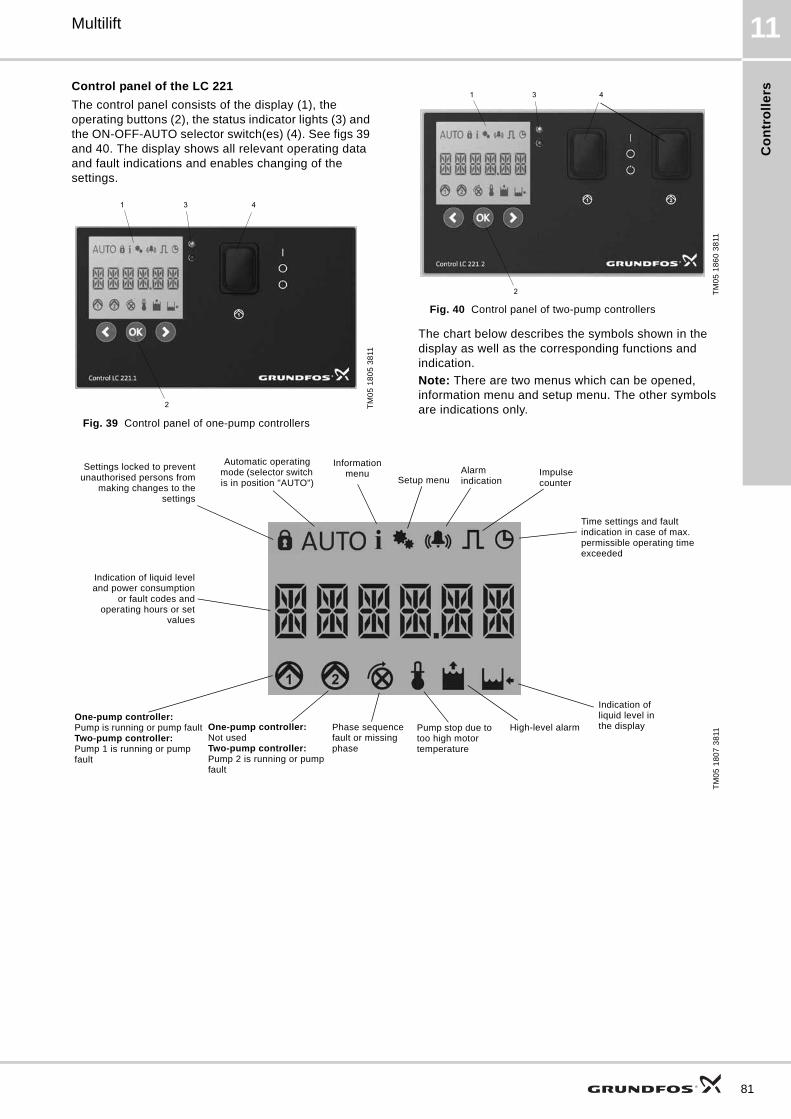
Co
ntr
oll
ers
Multilift 11
Control panel of the LC 221
The control panel consists of the display (1), the operating buttons (2), the status indicator lights (3) and the ON-OFF-AUTO selector switch(es) (4). See figs 39 and 40. The display shows all relevant operating data and fault indications and enables changing of the settings.
Fig. 39 Control panel of one-pump controllers
Fig. 40 Control panel of two-pump controllers
The chart below describes the symbols shown in the display as well as the corresponding functions and indication.
Note: There are two menus which can be opened, information menu and setup menu. The other symbols are indications only.T
M0
5 1
80
5 3
811
1
2
3 4
TM
05
18
60
38
11
1
2
3 4
TM
05
18
07
38
11
Settings locked to preventunauthorised persons from
making changes to thesettings
Automatic operating mode (selector switch is in position "AUTO") Setup menu
Information menu Alarm
indicationImpulse counter
Time settings and fault indication in case of max. permissible operating time exceeded
One-pump controller:Not usedTwo-pump controller:Pump 2 is running or pump fault
Indication of liquid leveland power consumption
or fault codes andoperating hours or set
values
One-pump controller:Pump is running or pump faultTwo-pump controller:Pump 1 is running or pump fault
Phase sequence fault or missing phase
Pump stop due to too high motor temperature
High-level alarm
Indication of liquid level in the display
81

Co
ntro
llers
82
Multilift11
Information menu
All status data and fault indications can be seen in the information menu. The information menu can be seen in all operating modes (ON-OFF-AUTO).
In the information menu the following data are shown:
• fault indications
• operating hours
• number of starts
• max. measured motor current (indication of worn-out bearing).
Setup menu
All settings are preset except for the start level. The start level depends on the inlet level and must be set during the start-up phase. However, in case adjustments are required, settings can be made easily via the setup menu.
The following settings can be made:
• start level
• rated current
• stop delay
• start delay
• alarm delay
• sensor selection*)
• sensor calibration*)
• sensor offset*)
• time for maintenance
• alarm reset (manually or automatically)
• reset to factory settings.*) These settings are only needed when changing sensor type.
The sensors are already calibrated.
Type key, LC 221 controller
Example LC 221 .1 .230 .1 .10
LC 221 = controller type
1 = one-pump controller2 = two-pump controller
Voltage [V]
1 = single-phase3 = three-phase
Max. operating current [A]

Fu
rth
er
pro
du
ct
do
cu
me
nta
tio
n
Multilift 12
12. Further product documentation
WebCAPSWebCAPS is a Web-based Computer Aided Product Selection program available on www.grundfos.com.
WebCAPS contains detailed information on more than 220,000 Grundfos products in more than 30 languages.
Information in WebCAPS is divided into six sections:
• Catalogue
• Literature
• Service
• Sizing
• Replacement
• CAD drawings.
Catalogue
Based on fields of application and pump types, this section contains the following:• technical data• curves (QH, Eta, P1, P2, etc.) which can be adapted to the
density and viscosity of the pumped liquid and show the number of pumps in operation
• product photos• dimensional drawings• wiring diagrams• quotation texts, etc.
Literature
This section contains all the latest documents of a given pump, such as• data booklets• installation and operating instructions• service documentation, such as Service kit catalogue and
Service kit instructions• quick guides• product brochures.
Service
This section contains an easy-to-use interactive service catalogue. Here you can find and identify service parts of both existing and discontinued Grundfos pumps.Furthermore, the section contains service videos showing you how to replace service parts.
83

Fu
rthe
r pro
du
ct d
oc
um
en
tatio
n
84
Multilift12
WinCAPS
Fig. 41 WinCAPS DVD
WinCAPS is a Windows-based Computer Aided Product Selection program containing detailed information on more than 220,000 Grundfos products in more than 30 languages.
The program contains the same features and functions as WebCAPS, but is an ideal solution if no internet connection is available.
WinCAPS is available on DVD and updated once a year.
Subject to alterations.
Sizing
This section is based on different fields of application and installation examples and gives easy step-by-step instructions in how to size a product:• Select the most suitable and efficient pump for your
installation.• Carry out advanced calculations based on energy,
consumption, payback periods, load profiles, life cycle costs, etc.
• Analyse your selected pump via the built-in life cycle cost tool.• Determine the flow velocity in wastewater applications, etc.
Replacement
In this section you find a guide to selecting and comparing replacement data of an installed pump in order to replace the pump with a more efficient Grundfos pump. The section contains replacement data of a wide range of pumps produced by other manufacturers than Grundfos.
Based on an easy step-by-step guide, you can compare Grundfos pumps with the one you have installed on your site. When you have specified the installed pump, the guide will suggest a number of Grundfos pumps which can improve both comfort and efficiency.
CAD drawings
In this section, it is possible to download 2-dimensional (2D) and 3-dimensional (3D) CAD drawings of most Grundfos pumps.
These formats are available in WebCAPS:
2-dimensional drawings:• .dxf, wireframe drawings• .dwg, wireframe drawings.
3-dimensional drawings:• .dwg, wireframe drawings (without surfaces)• .stp, solid drawings (with surfaces)• .eprt, E-drawings.
0 1

85

86

87

GRUNDFOS A/S . DK-8850 Bjerringbro . DenmarkTelephone: +45 87 50 14 00www.grundfos.com
The name Grundfos, the Grundfos logo, and the payoff be think innovate are registered trademarks owned by Grundfos Holding A/S or Grundfos A/S, Denmark. All rights reserved worldwide.
Being responsible is our foundationThinking ahead makes it possible
Innovation is the essence
98288126 0912
ECM: 1096644