Embed Size (px)
Citation preview

GRUNDFOS DATA BOOKLET
Grundfos Direct Sensor™
Pressure transmitters

Ta
ble
of c
on
ten
ts
2
Grundfos Direct Sensor™
1. Product introduction 3
2. Relative-pressure transmitter, industry (RPI) 4RPI general data 4RPI, 0 - 0.6 bar, technical data 6RPI, 0 - 1.0 bar, technical data 7RPI, 0 - 1.6 bar, technical data 8RPI, 0 - 2.5 bar, technical data 9RPI, 0 - 4.0 bar, technical data 10RPI, 0 - 6.0 bar, technical data 11RPI, 0 - 10.0 bar, technical data 12RPI, 0 - 16.0 bar, technical data 13RPI, 0 - 25.0 bar, technical data 14
3. Differential-pressure transmitter, industry (DPI V.2) 15DPI V.2 general data 15DPI V.2, 0 - 0.6 bar, technical data 17DPI V.2, 0 - 1.0 bar, technical data 18DPI V.2, 0 - 1.6 bar, technical data 19DPI V.2, 0 - 2.5 bar, technical data 20DPI V.2, 0 - 4.0 bar, technical data 21DPI V.2, 0 - 6.0 bar, technical data 22DPI V.2, 0 - 10.0 bar, technical data 23DPI V.2, 0 - 16.0 bar, technical data 24
4. Differential-pressure transmitter, industry (DPI) 25DPI general data 25DPI, 0 - 0.6 bar, technical data 26DPI, 0 - 1.0 bar, technical data 27DPI, 0 - 1.2 bar, technical data 28DPI, 0 - 1.6 bar, technical data 29DPI, 0 - 2.5 bar, technical data 30DPI, 0 - 4.0 bar, technical data 31DPI, 0 - 6.0 bar, technical data 32DPI, 0 - 10.0 bar, technical data 33
5. Relative-pressure transmitter, digital (RPD) 34RPD general data 34RPD, 0-10 bar, technical data 35
6. Relative-pressure transmitter, standard (RPS) 36RPS general data 36RPS, 0 - 0.6 bar, technical data 37RPS, 0 - 1.0 bar, technical data 38RPS, 0 - 1.6 bar, technical data 39RPS, 0 - 2.5 bar, technical data 40RPS, 0 - 4.0 bar, technical data 41RPS, 0 - 6.0 bar, technical data 42RPS, 0 - 10.0 bar, technical data 43
7. Differential-pressure transmitter, standard (DPS) 44DPS general data 44DPS, 0 - 0.6 bar, technical data 45DPS, 0 - 1.0 bar, technical data 46DPS, 0 - 1.6 bar, technical data 47DPS, 0 - 2.5 bar, technical data 48DPS, 0 - 4.0 bar, technical data 49DPS, 0 - 6.0 bar, technical data 50
8. Product range 51RPI transmitter 51DPI V.2 transmitter 52DPI transmitter 53
9. Accessories 54Transmitter interface, SI 001 PSU 54M12 cable 54Capillary tube 54Adaptor for mounting in Grundfos CR pumps 54Transmitter interface, SI 010 CNV 55
10. Appendix 56Temperature response of DPI V.2+T / RPI+T 56
11. Further product documentation 57WebCAPS 57WinCAPS 58GO CAPS 59

Pro
du
ct
intr
od
uc
tio
n
Grundfos Direct Sensor™ 1
1. Product introduction
This data booklet deals with Grundfos pressure transmitters.
Fig. 1 Grundfos pressure transmitters
The Grundfos Direct Sensors™ trademark is owned and controlled by the Grundfos Group.
There are three main ways to measure pressure:
• Absolute pressure is zero-referenced against a perfect vacuum.
• Relative pressure is zero-referenced against the ambient air pressure.
• Differential pressure is the difference between two pressures.
The Grundfos pressure transmitter range contains relative- and differential-pressure transmitters as well as relative- and differential-pressure transmitters combined with temperature transmitters. The latter are able to measure temperatures ranging from 0 to 100 °C, allowing the Grundfos transmitters to be used for a wide range of applications.
Relative-pressure transmitter (RPI, RPS, RPD)The central part of a relative-pressure transmitter is a transmitter chip which transforms the pressure into electrical signals. The difference between the ambient air pressure and the measured pressure will cause the transmitter chip to warp which is registered as a change of resistance in the strain gauges of a Wheatstone bridge. The change in resistance is converted into an analog output signal. The RPI+T also transforms the temperature of the medium into electrical signals.
The signals are calibrated, conditioned and presented analogously or digitally by means of a microprocessor. The pressure signals are temperature-compensated and linearised for the influence of temperature variations.
Differential-pressure transmitter (DPI, DPI V.2, DPS)The central part of a differential-pressure transmitter is a transmitter chip which transforms the differential pressure into electrical signals. The difference between the two pressures, called the differential pressure, will cause the transmitter chip to warp which is registered as a change of resistance in the strain gauges of a Wheatstone bridge. The change in resistance is converted into an analog output signal. The DPI+T V.2 also transforms the temperature of the medium into electrical signals.
Fig. 2 Schematic view of how the transmitter chip is affected by pressure on both sides
Transmitter chipSteady-state properties of silicon secure the transmitter chip against wear and tear. For the first time ever, lifelong nano-coating protection enables direct measurement (wet and wet-wet) in a cost-effective packaging for aggressive media. The secret is a metal-glass alloy coating, Silicoat®, which is extremely resistant to corrosion. Compared to conventional transmitter technologies, which incapsulate the unprotected measuring cell to protect it from the medium, Silicoat® ensures protection of the transmitter chip from aggressive media (pH2 - pH11) at temperatures up to 120 °C for the entire life of the product.
TM
04
50
34
- T
M0
4 7
86
5 -
TM
04
78
66
TM
03
40
55
14
06
3

Re
lativ
e-p
res
su
re tra
ns
mitte
r, ind
us
try (R
PI)
4
Grundfos Direct Sensor™2
2. Relative-pressure transmitter, industry (RPI)
RPI general data
Relative-pressure transmitter, industry
Fig. 3 RPI / RPI+T transmitter
Technical overview Grundfos Direct Sensors™, type RPI, is a series of industrial strength relative-pressure transmitters designed to be mounted directly on the unit, for example a pump. In addition to pressure, the RPI+T version is able to measure temperatures ranging from 0 to 100 °C.
The RPI has a standard M12 connector.
Applications• Water treatment and distribution
• light chemical industry
• water management
• pool and water resort
• heating
• air-conditioning
• cooling towers
• condensing units
• solar systems.
Features• Pressure ranges of 0 - 0.6, 0 - 1.0, 0 - 1.6, 0 - 2.5,
0 - 4.0, 0 - 6.0, 0 - 10.0, 0 - 16.0 and 0 - 25.0 bar.
• Approved for potable water, i.e. WRAS, ACS, others (pending).
• Wide temperature range of 0 to 100 °C (RPI+T).
Benefits• No moving parts
• compatible with wet, aggressive media
• cost-effective and robust design
• system solution with Grundfos pumps
• pressure and temperature measurement in one transmitter (RPI+T).
Electrical connections
Fig. 4 Electrical connections
* Common ground for pressure and temperature signals.Power supply (screened cable): SELV or PELV.
TM
04
78
65
25
10
TM
04
71
56
16
10
Pin 1 2 3 4
Wire colour Brown White Blue Black
Output 4-20 mA
+ Not used - Not used
Output 2 x 0-10 V
+Pressure
signal-*
Temperature signal
1
3
4
2

Re
lati
ve
-pre
ss
ure
tra
ns
mit
ter,
in
du
str
y (
RP
I)
Grundfos Direct Sensor™ 2
Type key
Code Type designation RPI /··0-0.6 b /1 /C /N /..... . /VG6 /.. /.. . /W··1
RPIProduct groupRelative-pressure transmitter, industry
Range0 - 0.6
bUnitbar
1Generation1st generation
CF
Electrical output type4-20 mA, 2-wire2 × 0-10 V
NTransmitter connector or cable type and cable connector in transmitter endM12 x 1, 4-pin male
Cable lengthNA
Cable connector opposite transmitterNA
EV
G
6
Sealing material and classFirst letter:EPDM (approved for potable water)FKM (for use in oily media)Second letter:Gel-filledThird letter:IP67
BCGQS
MaterialBrassCompositeCast ironStainless-steel flow pipe with composite insert (QT)Stainless steel
Dimension of mechanical connection
Mechanical connection type
WA1
PackagingBlister packing, standard Grundfos cardboard Set with pre-assembled components1 piece
5

Re
lativ
e-p
res
su
re tra
ns
mitte
r, ind
us
try (R
PI)
6
Grundfos Direct Sensor™2
RPI, 0 - 0.6 bar, technical data
Relative-pressure transmitter, industry
Fig. 5 RPI / RPI+T transmitter
Dimensions [mm]
Fig. 6 Dimensions of RPI / RPI+T transmitter
Output signals
Fig. 7 Pressure response of RPI transmitter
Fig. 8 Pressure and temperature response of RPI+T transmitter
Specifications
TM
04
92
40
35
10
TM
04
92
37
35
10
TM
04
91
89
36
10
TM
04
91
90
36
10
0 0.6 bar
20 mA
4 mA
0 0.6 bar
10 V
0 °C 100 °C
0 V
Pressure
Measuring range 0 - 0.6 bar
Accuracy (± 1σ), 0-80 °C ± 2 % FS
Accuracy (± 1σ), -30 - +100 °C ± 2.5 % FS
Response time< 100 ms
(typical 50 ms)
Resolution 1/1000 FS
Temperature (only RPI with temperature transmitter)
Range 0-100 °C
Accuracy (± 1), 0-80 °C ± 1 °C
Accuracy (± 1), 0-100 °C ± 2 °C
Response time for transmitter electronics
< 100 ms(typical 50 ms)
Resolution 0.1 °C
Media and environment
Medium typesLiquids, gasses and air, compatible
with the wetted materials
Medium temperature (operation)
-30 - +120 °C
Ambient air temperature (operation)
-25 - +60 °C
Storage temperature -55 - +70 °C
Humidity 0-95 % RH, non-condensing
System burst pressure 60 bar
Electrical data (only RPI without temperature transmitter)
Power supply RPI 12.5 - 30 VDC
Output signals - cut off
4-20 mA21 mA
Power consumption Max. 660 mW
Load impedance
Max. 60 Ω at 12.5 VDCMax. 100 Ω at 13.3 VDCMax. 600 Ω at 24 VDCMax. 900 Ω at 30 VDC
Electrical data (only RPI with temperature transmitter)
Power supply RPI+T 16.6 - 30 VDC
Output signals - cut off
0-10 VDC10.5 VDC
Maximum signal cable length 30 m
Power consumption Max. 300 mW
Load impedance Min. 10 kΩ
Transmitter materials
Measuring element Silicon-based MEMS transmitter
Packing material EPDM or FKM rubber
Transmitter housing Stainless steel 1.4404
Wetted materialsCorrosion-resistant coating
EPDM or FKM rubberStainless steel 1.4404
Environmental standards
Enclosure class IP67
Temperature cycling IEC 68-2-14
Vibration (non-destructive) 20-2000 Hz, 10 G, 4 h
Electromagnetic compatibility EN 61326-1

Re
lati
ve
-pre
ss
ure
tra
ns
mit
ter,
in
du
str
y (
RP
I)
Grundfos Direct Sensor™ 2
RPI, 0 - 1.0 bar, technical data
Relative-pressure transmitter, industry
Fig. 9 RPI / RPI+T transmitter
Dimensions [mm]
Fig. 10 Dimensions of RPI / RPI+T transmitter
Output signals
Fig. 11 Pressure response of RPI transmitter
Fig. 12 Pressure and temperature response of RPI+T transmitter
Specifications
TM
04
92
40
35
10
TM
04
92
37
35
10
TM
04
91
89
36
10
TM
04
91
90
36
10
0 1.0 bar
20 mA
4 mA
0 1.0 bar
10 V
0 °C 100 °C
0 V
Pressure
Measuring range 0 - 1.0 bar
Accuracy (± 1σ), 0-80 °C ± 2 % FS
Accuracy (± 1σ), -30 - +100 °C ± 2.5 % FS
Response time< 100 ms
(typical 50 ms)
Resolution 1/1000 FS
Temperature (only RPI with temperature transmitter)
Range 0-100 °C
Accuracy (± 1), 0-80 °C ± 1 °C
Accuracy (± 1), 0-100 °C ± 2 °C
Response time for transmitter electronics
< 100 ms(typical 50 ms)
Resolution 0.1 °C
Media and environment
Medium typesLiquids, gasses and air, compatible
with the wetted materials
Medium temperature (operation)
-30 - +120 °C
Ambient air temperature (operation)
-25 - +60 °C
Storage temperature -55 - +70 °C
Humidity 0-95 % RH, non-condensing
System burst pressure 60 bar
Electrical data (only RPI without temperature transmitter)
Power supply RPI 12.5 - 30 VDC
Output signals - cut off
4-20 mA21 mA
Power consumption Max. 660 mW
Load impedance
Max. 60 Ω at 12.5 VDCMax. 100 Ω at 13.3 VDCMax. 600 Ω at 24 VDCMax. 900 Ω at 30 VDC
Electrical data (only RPI with temperature transmitter)
Power supply RPI+T 16.6 - 30 VDC
Output signals - cut off
0-10 VDC10.5 VDC
Maximum signal cable length 30 m
Power consumption Max. 300 mW
Load impedance Min. 10 kΩ
Transmitter materials
Measuring element Silicon-based MEMS transmitter
Packing material EPDM or FKM rubber
Transmitter housing Stainless steel 1.4404
Wetted materialsCorrosion-resistant coating
EPDM or FKM rubberStainless steel 1.4404
Environmental standards
Enclosure class IP67
Temperature cycling IEC 68-2-14
Vibration (non-destructive) 20-2000 Hz, 10 G, 4 h
Electromagnetic compatibility EN 61326-1
7

Re
lativ
e-p
res
su
re tra
ns
mitte
r, ind
us
try (R
PI)
8
Grundfos Direct Sensor™2
RPI, 0 - 1.6 bar, technical data
Relative-pressure transmitter, industry
Fig. 13 RPI / RPI+T transmitter
Dimensions [mm]
Fig. 14 Dimensions of RPI / RPI+T transmitter
Output signals
Fig. 15 Pressure response of RPI transmitter
Fig. 16 Pressure and temperature response of RPI+T transmitter
Specifications
TM
04
92
40
35
10
TM
04
92
37
35
10
TM
04
91
89
36
10
TM
04
91
90
36
10
0 1.6 bar
20 mA
4 mA
0 1.6 bar
10 V
0 °C 100 °C
0 V
Pressure
Measuring range 0 - 1.6 bar
Accuracy (± 1σ), 0-80 °C ± 2 % FS
Accuracy (± 1σ), -30 - +100 °C ± 2.5 % FS
Response time< 100 ms
(typical 50 ms)
Resolution 1/1000 FS
Temperature (only RPI with temperature transmitter)
Range 0-100 °C
Accuracy (± 1), 0-80 °C ± 1 °C
Accuracy (± 1), 0-100 °C ± 2 °C
Response time for transmitter electronics
< 100 ms(typical 50 ms)
Resolution 0.1 °C
Media and environment
Medium typesLiquids, gasses and air, compatible
with the wetted materials
Medium temperature (operation)
-30 - +120 °C
Ambient air temperature (operation)
-25 - +60 °C
Storage temperature -55 - +70 °C
Humidity 0-95 % RH, non-condensing
System burst pressure 60 bar
Electrical data (only RPI without temperature transmitter)
Power supply RPI 12.5 - 30 VDC
Output signals - cut off
4-20 mA21 mA
Power consumption Max. 660 mW
Load impedance
Max. 60 Ω at 12.5 VDCMax. 100 Ω at 13.3 VDCMax. 600 Ω at 24 VDCMax. 900 Ω at 30 VDC
Electrical data (only RPI with temperature transmitter)
Power supply RPI+T 16.6 - 30 VDC
Output signals - cut off
0-10 VDC10.5 VDC
Maximum signal cable length 30 m
Power consumption Max. 300 mW
Load impedance Min. 10 kΩ
Transmitter materials
Measuring element Silicon-based MEMS transmitter
Packing material EPDM or FKM rubber
Transmitter housing Stainless steel 1.4404
Wetted materialsCorrosion-resistant coating
EPDM or FKM rubberStainless steel 1.4404
Environmental standards
Enclosure class IP67
Temperature cycling IEC 68-2-14
Vibration (non-destructive) 20-2000 Hz, 10 G, 4 h
Electromagnetic compatibility EN 61326-1

Re
lati
ve
-pre
ss
ure
tra
ns
mit
ter,
in
du
str
y (
RP
I)
Grundfos Direct Sensor™ 2
RPI, 0 - 2.5 bar, technical data
Relative-pressure transmitter, industry
Fig. 17 RPI / RPI+T transmitter
Dimensions [mm]
Fig. 18 Dimensions of RPI / RPI+T transmitter
Output signals
Fig. 19 Pressure response of RPI transmitter
Fig. 20 Pressure and temperature response of RPI+T transmitter
Specifications
TM
04
92
40
35
10
TM
04
92
37
35
10
TM
04
91
89
36
10
TM
04
91
90
36
10
0 2.5 bar
20 mA
4 mA
0 2.5 bar
10 V
0 °C 100 °C
0 V
Pressure
Measuring range 0 - 2.5 bar
Accuracy (± 1σ), 0-80 °C ± 2 % FS
Accuracy (± 1σ), -30 - +100 °C ± 2.5 % FS
Response time< 100 ms
(typical 50 ms)
Resolution 1/1000 FS
Temperature (only RPI with temperature transmitter)
Range 0-100 °C
Accuracy (± 1), 0-80 °C ± 1 °C
Accuracy (± 1), 0-100 °C ± 2 °C
Response time for transmitter electronics
< 100 ms(typical 50 ms)
Resolution 0.1 °C
Media and environment
Medium typesLiquids, gasses and air, compatible
with the wetted materials
Medium temperature (operation)
-30 - +120 °C
Ambient air temperature (operation)
-25 - +60 °C
Storage temperature -55 - +70 °C
Humidity 0-95 % RH, non-condensing
System burst pressure 60 bar
Electrical data (only RPI without temperature transmitter)
Power supply RPI 12.5 - 30 VDC
Output signals - cut off
4-20 mA21 mA
Power consumption Max. 660 mW
Load impedance
Max. 60 Ω at 12.5 VDCMax. 100 Ω at 13.3 VDCMax. 600 Ω at 24 VDCMax. 900 Ω at 30 VDC
Electrical data (only RPI with temperature transmitter)
Power supply RPI+T 16.6 - 30 VDC
Output signals - cut off
0-10 VDC10.5 VDC
Maximum signal cable length 30 m
Power consumption Max. 300 mW
Load impedance Min. 10 kΩ
Transmitter materials
Measuring element Silicon-based MEMS transmitter
Packing material EPDM or FKM rubber
Transmitter housing Stainless steel 1.4404
Wetted materialsCorrosion-resistant coating
EPDM or FKM rubberStainless steel 1.4404
Environmental standards
Enclosure class IP67
Temperature cycling IEC 68-2-14
Vibration (non-destructive) 20-2000 Hz, 10 G, 4 h
Electromagnetic compatibility EN 61326-1
9
Re
lativ
e-p
res
su
re tra
ns
mitte
r, ind
us
try (R
PI)
10
Grundfos Direct Sensor™2
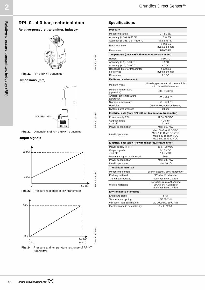
RPI, 0 - 4.0 bar, technical data
Relative-pressure transmitter, industry
Fig. 21 RPI / RPI+T transmitter
Dimensions [mm]
Fig. 22 Dimensions of RPI / RPI+T transmitter
Output signals
Fig. 23 Pressure response of RPI transmitter
Fig. 24 Pressure and temperature response of RPI+T transmitter
Specifications
TM
04
92
40
35
10
TM
04
92
37
35
10
TM
04
91
89
36
10
TM
04
91
90
36
10
0 4.0 bar
20 mA
4 mA
0 4.0 bar
10 V
0 °C 100 °C
0 V
Pressure
Measuring range 0 - 4.0 bar
Accuracy (± 1σ), 0-80 °C ± 2 % FS
Accuracy (± 1σ), -30 - +100 °C ± 2.5 % FS
Response time< 100 ms
(typical 50 ms)
Resolution 1/1000 FS
Temperature (only RPI with temperature transmitter)
Range 0-100 °C
Accuracy (± 1), 0-80 °C ± 1 °C
Accuracy (± 1), 0-100 °C ± 2 °C
Response time for transmitter electronics
< 100 ms(typical 50 ms)
Resolution 0.1 °C
Media and environment
Medium typesLiquids, gasses and air, compatible
with the wetted materials
Medium temperature (operation)
-30 - +120 °C
Ambient air temperature (operation)
-25 - +60 °C
Storage temperature -55 - +70 °C
Humidity 0-95 % RH, non-condensing
System burst pressure 60 bar
Electrical data (only RPI without temperature transmitter)
Power supply RPI 12.5 - 30 VDC
Output signals - cut off
4-20 mA21 mA
Power consumption Max. 660 mW
Load impedance
Max. 60 Ω at 12.5 VDCMax. 100 Ω at 13.3 VDCMax. 600 Ω at 24 VDCMax. 900 Ω at 30 VDC
Electrical data (only RPI with temperature transmitter)
Power supply RPI+T 16.6 - 30 VDC
Output signals - cut off
0-10 VDC10.5 VDC
Maximum signal cable length 30 m
Power consumption Max. 300 mW
Load impedance Min. 10 kΩ
Transmitter materials
Measuring element Silicon-based MEMS transmitter
Packing material EPDM or FKM rubber
Transmitter housing Stainless steel 1.4404
Wetted materialsCorrosion-resistant coating
EPDM or FKM rubberStainless steel 1.4404
Environmental standards
Enclosure class IP67
Temperature cycling IEC 68-2-14
Vibration (non-destructive) 20-2000 Hz, 10 G, 4 h
Electromagnetic compatibility EN 61326-1

Re
lati
ve
-pre
ss
ure
tra
ns
mit
ter,
in
du
str
y (
RP
I)
Grundfos Direct Sensor™ 2
RPI, 0 - 6.0 bar, technical data
Relative-pressure transmitter, industry
Fig. 25 RPI / RPI+T transmitter
Dimensions [mm]
Fig. 26 Dimensions of RPI / RPI+T transmitter
Output signals
Fig. 27 Pressure response of RPI transmitter
Fig. 28 Pressure and temperature response of RPI+T transmitter
Specifications
TM
04
92
40
35
10
TM
04
92
37
35
10
TM
04
91
89
36
10
TM
04
91
90
36
10
0 6.0 bar
20 mA
4 mA
0 6.0 bar
10 V
0 °C 100 °C
0 V
Pressure
Measuring range 0 - 6.0 bar
Accuracy (± 1σ), 0-80 °C ± 2 % FS
Accuracy (± 1σ), -30 - +100 °C ± 2.5 % FS
Response time< 100 ms
(typical 50 ms)
Resolution 1/1000 FS
Temperature (only RPI with temperature transmitter)
Range 0-100 °C
Accuracy (± 1), 0-80 °C ± 1 °C
Accuracy (± 1), 0-100 °C ± 2 °C
Response time for transmitter electronics
< 100 ms(typical 50 ms)
Resolution 0.1 °C
Media and environment
Medium typesLiquids, gasses and air, compatible
with the wetted materials
Medium temperature (operation)
-30 - +120 °C
Ambient air temperature (operation)
-25 - +60 °C
Storage temperature -55 - +70 °C
Humidity 0-95 % RH, non-condensing
System burst pressure 60 bar
Electrical data (only RPI without temperature transmitter)
Power supply RPI 12.5 - 30 VDC
Output signals - cut off
4-20 mA21 mA
Power consumption Max. 660 mW
Load impedance
Max. 60 Ω at 12.5 VDCMax. 100 Ω at 13.3 VDCMax. 600 Ω at 24 VDCMax. 900 Ω at 30 VDC
Electrical data (only RPI with temperature transmitter)
Power supply RPI+T 16.6 - 30 VDC
Output signals - cut off
0-10 VDC10.5 VDC
Maximum signal cable length 30 m
Power consumption Max. 300 mW
Load impedance Min. 10 kΩ
Transmitter materials
Measuring element Silicon-based MEMS transmitter
Packing material EPDM or FKM rubber
Transmitter housing Stainless steel 1.4404
Wetted materialsCorrosion-resistant coating
EPDM or FKM rubberStainless steel 1.4404
Environmental standards
Enclosure class IP67
Temperature cycling IEC 68-2-14
Vibration (non-destructive) 20-2000 Hz, 10 G, 4 h
Electromagnetic compatibility EN 61326-1
11

Re
lativ
e-p
res
su
re tra
ns
mitte
r, ind
us
try (R
PI)
12
Grundfos Direct Sensor™2
RPI, 0 - 10.0 bar, technical data
Relative-pressure transmitter, industry
Fig. 29 RPI / RPI+T transmitter
Dimensions [mm]
Fig. 30 Dimensions of RPI / RPI+T transmitter
Output signals
Fig. 31 Pressure response of RPI transmitter
Fig. 32 Pressure and temperature response of RPI+T transmitter
Specifications
TM
04
92
40
35
10
TM
04
92
37
35
10
TM
04
91
89
36
10
TM
04
91
90
36
10
0 10.0 bar
20 mA
4 mA
0 10.0 bar
10 V
0 °C 100 °C
0 V
Pressure
Measuring range 0 - 10.0 bar
Accuracy (± 1σ), 0-80 °C ± 2 % FS
Accuracy (± 1σ), -30 - +100 °C ± 2.5 % FS
Response time< 100 ms
(typical 50 ms)
Resolution 1/1000 FS
Temperature (only RPI with temperature transmitter)
Range 0-100 °C
Accuracy (± 1), 0-80 °C ± 1 °C
Accuracy (± 1), 0-100 °C ± 2 °C
Response time for transmitter electronics
< 100 ms(typical 50 ms)
Resolution 0.1 °C
Media and environment
Medium typesLiquids, gasses and air, compatible
with the wetted materials
Medium temperature (operation)
-30 - +120 °C
Ambient air temperature (operation)
-25 - +60 °C
Storage temperature -55 - +70 °C
Humidity 0-95 % RH, non-condensing
System burst pressure 60 bar
Electrical data (only RPI without temperature transmitter)
Power supply RPI 12.5 - 30 VDC
Output signals - cut off
4-20 mA21 mA
Power consumption Max. 660 mW
Load impedance
Max. 60 Ω at 12.5 VDCMax. 100 Ω at 13.3 VDCMax. 600 Ω at 24 VDCMax. 900 Ω at 30 VDC
Electrical data (only RPI with temperature transmitter)
Power supply RPI+T 16.6 - 30 VDC
Output signals - cut off
0-10 VDC10.5 VDC
Maximum signal cable length 30 m
Power consumption Max. 300 mW
Load impedance Min. 10 kΩ
Transmitter materials
Measuring element Silicon-based MEMS transmitter
Packing material EPDM or FKM rubber
Transmitter housing Stainless steel 1.4404
Wetted materialsCorrosion-resistant coating
EPDM or FKM rubberStainless steel 1.4404
Environmental standards
Enclosure class IP67
Temperature cycling IEC 68-2-14
Vibration (non-destructive) 20-2000 Hz, 10 G, 4 h
Electromagnetic compatibility EN 61326-1

Re
lati
ve
-pre
ss
ure
tra
ns
mit
ter,
in
du
str
y (
RP
I)
Grundfos Direct Sensor™ 2
RPI, 0 - 16.0 bar, technical data
Relative-pressure transmitter, industry
Fig. 33 RPI / RPI+T transmitter
Dimensions [mm]
Fig. 34 Dimensions of RPI / RPI+T transmitter
Output signals
Fig. 35 Pressure response of RPI transmitter
Fig. 36 Pressure and temperature response of RPI+T transmitter
Specifications
TM
04
92
40
35
10
TM
04
92
37
35
10
TM
04
91
89
36
10
TM
04
91
90
36
10
0 16.0 bar
20 mA
4 mA
0 16.0 bar
10 V
0 °C 100 °C
0 V
Pressure
Measuring range 0 - 16.0 bar
Accuracy (± 1σ), 0-80 °C ± 2 % FS
Accuracy (± 1σ), -30 - +100 °C ± 2.5 % FS
Response time< 100 ms
(typical 50 ms)
Resolution 1/1000 FS
Temperature (only RPI with temperature transmitter)
Range 0-100 °C
Accuracy (± 1), 0-80 °C ± 1 °C
Accuracy (± 1), 0-100 °C ± 2 °C
Response time for transmitter electronics
< 100 ms(typical 50 ms)
Resolution 0.1 °C
Media and environment
Medium typesLiquids, gasses and air, compatible
with the wetted materials
Medium temperature (operation)
-30 - +120 °C
Ambient air temperature (operation)
-25 - +60 °C
Storage temperature -55 - +70 °C
Humidity 0-95 % RH, non-condensing
System burst pressure 60 bar
Electrical data (only RPI without temperature transmitter)
Power supply RPI 12.5 - 30 VDC
Output signals - cut off
4-20 mA21 mA
Power consumption Max. 660 mW
Load impedance
Max. 60 Ω at 12.5 VDCMax. 100 Ω at 13.3 VDCMax. 600 Ω at 24 VDCMax. 900 Ω at 30 VDC
Electrical data (only RPI with temperature transmitter)
Power supply RPI+T 16.6 - 30 VDC
Output signals - cut off
0-10 VDC10.5 VDC
Maximum signal cable length 30 m
Power consumption Max. 300 mW
Load impedance Min. 10 kΩ
Transmitter materials
Measuring element Silicon-based MEMS transmitter
Packing material EPDM or FKM rubber
Transmitter housing Stainless steel 1.4404
Wetted materialsCorrosion-resistant coating
EPDM or FKM rubberStainless steel 1.4404
Environmental standards
Enclosure class IP67
Temperature cycling IEC 68-2-14
Vibration (non-destructive) 20-2000 Hz, 10 G, 4 h
Electromagnetic compatibility EN 61326-1
13

Re
lativ
e-p
res
su
re tra
ns
mitte
r, ind
us
try (R
PI)
14
Grundfos Direct Sensor™2
RPI, 0 - 25.0 bar, technical data
Relative-pressure transmitter, industry
Fig. 37 RPI / RPI+T transmitter
Dimensions [mm]
Fig. 38 Dimensions of RPI / RPI+T transmitter
Output signals
Fig. 39 Pressure response of RPI transmitter
Fig. 40 Pressure and temperature response of RPI+T transmitter
Specifications
TM
04
92
40
35
10
TM
04
92
37
35
10
TM
04
91
89
36
10
TM
04
91
90
36
10
0 25.0 bar
20 mA
4 mA
0 25.0 bar
10 V
0 °C 100 °C
0 V
Pressure
Measuring range 0 - 25.0 bar
Accuracy (± 1σ), 0-80 °C ± 2 % FS
Accuracy (± 1σ), -30 - +100 °C ± 2.5 % FS
Response time< 100 ms
(typical 50 ms)
Resolution 1/1000 FS
Temperature (only RPI with temperature transmitter)
Range 0-100 °C
Accuracy (± 1), 0-80 °C ± 1 °C
Accuracy (± 1), 0-100 °C ± 2 °C
Response time for transmitter electronics
< 100 ms(typical 50 ms)
Resolution 0.1 °C
Media and environment
Medium typesLiquids, gasses and air, compatible
with the wetted materials
Medium temperature (operation)
-30 - +120 °C
Ambient air temperature (operation)
-25 - +60 °C
Storage temperature -55 - +70 °C
Humidity 0-95 % RH, non-condensing
System burst pressure 60 bar
Electrical data (only RPI without temperature transmitter)
Power supply RPI 12.5 - 30 VDC
Output signals - cut off
4-20 mA21 mA
Power consumption Max. 660 mW
Load impedance
Max. 60 Ω at 12.5 VDCMax. 100 Ω at 13.3 VDCMax. 600 Ω at 24 VDCMax. 900 Ω at 30 VDC
Electrical data (only RPI with temperature transmitter)
Power supply RPI+T 16.6 - 30 VDC
Output signals - cut off
0-10 VDC10.5 VDC
Maximum signal cable length 30 m
Power consumption Max. 300 mW
Load impedance Min. 10 kΩ
Transmitter materials
Measuring element Silicon-based MEMS transmitter
Packing material EPDM or FKM rubber
Transmitter housing Stainless steel 1.4404
Wetted materialsCorrosion-resistant coating
EPDM or FKM rubberStainless steel 1.4404
Environmental standards
Enclosure class IP67
Temperature cycling IEC 68-2-14
Vibration (non-destructive) 20-2000 Hz, 10 G, 4 h
Electromagnetic compatibility EN 61326-1

Dif
fere
nti
al-
pre
ss
ure
tra
ns
mit
ter,
in
du
str
y (
DP
I V
.2)
Grundfos Direct Sensor™ 3
3. Differential-pressure transmitter, industry (DPI V.2)
DPI V.2 general data
Differential-pressure transmitter, industry, V.2
Fig. 41 DPI V.2 transmitter
Technical overview Grundfos Direct Sensors™, type DPI V.2, is a series of industrial strength differential-pressure transmitters designed to be mounted directly on the unit, for example a pump. In addition to pressure, the DPI V.2+T version is able to measure temperatures ranging from 0 to 100 °C.
The DPI V.2 has a standard M12 connector.
Applications• Water treatment and distribution
• light chemical industry
• water management
• pool and water resort
• heating
• air-conditioning
• cooling towers
• condensing units
• solar systems.
Features• Pressure ranges of 0 - 0.6, 0 - 1.0, 0 - 1.6, 0 - 2.5,
0 - 4.0, 0 - 6.0, 0 - 10.0 and 0 - 16.0 bar.
• Approved for potable water, i.e. WRAS, ACS, others (pending).
• Wide temperature range of 0 to 100 °C (DPI V.2+T).
Benefits• No moving parts
• compatible with wet, aggressive media
• cost-effective and robust design
• system solution with Grundfos pumps
• pressure and temperature measurement in one transmitter (DPI V.2+T).
Electrical connections
Fig. 42 Electrical connections
* Common ground for pressure and temperature signals.Power supply (screened cable): SELV or PELV.
TM
04
78
66
25
10
TM
04
71
56
16
10
Pin 1 2 3 4
Wire colour Brown White Blue Black
Output 4-20 mA
+ Not used - Not used
Output 2 x 0-10 V
+Pressure
signal-*
Temperature signal
1
3
4
2
15

Diffe
ren
tial-p
res
su
re tra
ns
mitte
r, ind
us
try (D
PI V
.2)
16
Grundfos Direct Sensor™3
Type key
Code Type designation DPI -··0-0.6 b -1 -C -M 2.000 -X -VG6 .. .. . -SW·1
DPIProduct groupDifferential-pressure transmitter, industry
Range0 - 0.6
bUnitbar
1Generation1st generation
CF
Electrical output type4-20 mA, 2-wire 2 × 0-10 V
NTransmitter connector or cable type and cable connector in transmitter endM12 × 1, 4-pin male
2.000 Cable length
MCable connector opposite transmitterM12 × 1, female straight, screened 4-wire cable
EV
G
6
Sealing material and classFirst letter:EPDM (approved for potable water)FKM (for use in oily media)Second letter:Gel-filledThird letter:IP67
BCGQS
MaterialBrassCompositeCast ironStainless-steel flow pipe with composite insert (QT)Stainless steel
Dimension of mechanical connection
Mechanical connection type
SW1
PackagingSetBlister packing, standard Grundfos cardboard, set with pre-assembled components1 piece

Dif
fere
nti
al-
pre
ss
ure
tra
ns
mit
ter,
in
du
str
y (
DP
I V
.2)
Grundfos Direct Sensor™ 3
DPI V.2, 0 - 0.6 bar, technical data
Differential-pressure transmitter, industry, V.2
Fig. 43 DPI V.2 / DPI V.2+T transmitter
Dimensions [mm]
Fig. 44 Dimensions of DPI V.2 / DPI V.2+T transmitter
Output signals
Fig. 45 Pressure response of DPI V.2 transmitter
Fig. 46 Pressure and temperature response of DPI V.2+T transmitter
Specifications
TM
04
92
39
35
10
TM
04
92
37
35
10
TM
04
91
89
36
10
TM
04
91
90
36
10
7/16 - 20 UNF
1/2
0 0.6 bar
20 mA
4 mA
0 0.6 bar
10 V
0 °C 100 °C
0 V
Pressure
Measuring range 0 - 0.6 bar
Accuracy (± 1σ), 0-80 °C ± 2 % FS
Accuracy (± 1σ), -30 - +100 °C ± 2.5 % FS
Response time< 100 ms
(typical 50 ms)
Resolution 1/1000 FS
Temperature (only DPI V.2 with temperature transmitter)
Range (relative) 0-100 °C
Accuracy (± 1), 0-80 °C ± 1 °C
Accuracy (± 1), 0-100 °C ± 2 °C
Response time for transmitter electronics
< 100 ms(typical 50 ms)
Resolution 0.1 °C
Media and environment
Medium typesLiquids, gasses and air, compatible
with the wetted materials
Medium temperature (operation)
-30 - +120 °C
Ambient air temperature (operation)
-25 - +60 °C
Storage temperature -55 - +70 °C
Humidity 0-95 % RH, non-condensing
System burst pressure 60 bar
Electrical data (only DPI V.2 without temperature transmitter)
Power supply DPI V.2 12.5 - 30 VDC
Output signals - cut off
4-20 mA21 mA
Power consumption Max. 660 mW
Load impedance
Max. 60 Ω at 12.5 VDCMax. 100 Ω at 13.3 VDCMax. 600 Ω at 24 VDCMax. 900 Ω at 30 VDC
Electrical data (only DPI V.2 with temperature transmitter)
Power supply DPI V.2+T 16.6 - 30 VDC
Output signals - cut off
0-10 VDC10.5 VDC
Maximum signal cable length 30 m
Power consumption Max. 300 mW
Load impedance Min. 10 kΩ
Transmitter materials
Measuring element Silicon-based MEMS transmitter
Packing material EPDM or FKM rubber
Transmitter housing Stainless steel 1.4404
Wetted materialsCorrosion-resistant coating
EPDM or FKM rubberStainless steel 1.4404
Environmental standards
Enclosure class IP67
Temperature cycling IEC 68-2-14
Vibration (non-destructive) 20-2000 Hz, 10 G, 4 h
Electromagnetic compatibility EN 61326-1
17

Diffe
ren
tial-p
res
su
re tra
ns
mitte
r, ind
us
try (D
PI V
.2)
18
Grundfos Direct Sensor™3
DPI V.2, 0 - 1.0 bar, technical data
Differential-pressure transmitter, industry, V.2
Fig. 47 DPI V.2 / DPI V.2+T transmitter
Dimensions [mm]
Fig. 48 Dimensions of DPI V.2 / DPI V.2+T transmitter
Output signals
Fig. 49 Pressure response of DPI V.2 transmitter
Fig. 50 Pressure and temperature response of DPI V.2+T transmitter
Specifications
TM
04
92
39
35
10
TM
04
92
37
35
10
TM
04
91
89
36
10
TM
04
91
90
36
10
7/16 - 20 UNF
1/2
0 1.0 bar
20 mA
4 mA
0 1.0 bar
10 V
0 °C 100 °C
0 V
Pressure
Measuring range 0 - 1.0 bar
Accuracy (± 1σ), 0-80 °C ± 2 % FS
Accuracy (± 1σ), -30 - +100 °C ± 2.5 % FS
Response time< 100 ms
(typical 50 ms)
Resolution 1/1000 FS
Temperature (only DPI V.2 with temperature transmitter)
Range (relative) 0-100 °C
Accuracy (± 1), 0-80 °C ± 1 °C
Accuracy (± 1), 0-100 °C ± 2 °C
Response time for transmitter electronics
< 100 ms(typical 50 ms)
Resolution 0.1 °C
Media and environment
Medium typesLiquids, gasses and air, compatible
with the wetted materials
Medium temperature (operation)
-30 - +120 °C
Ambient air temperature (operation)
-25 - +60 °C
Storage temperature -55 - +70 °C
Humidity 0-95 % RH, non-condensing
System burst pressure 60 bar
Electrical data (only DPI V.2 without temperature transmitter)
Power supply DPI V.2 12.5 - 30 VDC
Output signals - cut off
4-20 mA21 mA
Power consumption Max. 660 mW
Load impedance
Max. 60 Ω at 12.5 VDCMax. 100 Ω at 13.3 VDCMax. 600 Ω at 24 VDCMax. 900 Ω at 30 VDC
Electrical data (only DPI V.2 with temperature transmitter)
Power supply DPI V.2+T 16.6 - 30 VDC
Output signals - cut off
0-10 VDC10.5 VDC
Maximum signal cable length 30 m
Power consumption Max. 300 mW
Load impedance Min. 10 kΩ
Transmitter materials
Measuring element Silicon-based MEMS transmitter
Packing material EPDM or FKM rubber
Transmitter housing Stainless steel 1.4404
Wetted materialsCorrosion-resistant coating
EPDM or FKM rubberStainless steel 1.4404
Environmental standards
Enclosure class IP67
Temperature cycling IEC 68-2-14
Vibration (non-destructive) 20-2000 Hz, 10 G, 4 h
Electromagnetic compatibility EN 61326-1

Dif
fere
nti
al-
pre
ss
ure
tra
ns
mit
ter,
in
du
str
y (
DP
I V
.2)
Grundfos Direct Sensor™ 3
DPI V.2, 0 - 1.6 bar, technical data
Differential-pressure transmitter, industry, V.2
Fig. 51 DPI V.2 / DPI V.2+T transmitter
Dimensions [mm]
Fig. 52 Dimensions of DPI V.2 / DPI V.2+T transmitter
Output signals
Fig. 53 Pressure response of DPI V.2 transmitter
Fig. 54 Pressure and temperature response of DPI V.2+T transmitter
Specifications
TM
04
92
39
35
10
TM
04
92
37
35
10
TM
04
91
89
36
10
TM
04
91
90
36
10
7/16 - 20 UNF
1/2
0 1.6 bar
20 mA
4 mA
0 1.6 bar
10 V
0 °C 100 °C
0 V
Pressure
Measuring range 0 - 1.6 bar
Accuracy (± 1σ), 0-80 °C ± 2 % FS
Accuracy (± 1σ), -30 - +100 °C ± 2.5 % FS
Response time< 100 ms
(typical 50 ms)
Resolution 1/1000 FS
Temperature (only DPI V.2 with temperature transmitter)
Range (relative) 0-100 °C
Accuracy (± 1), 0-80 °C ± 1 °C
Accuracy (± 1), 0-100 °C ± 2 °C
Response time for transmitter electronics
< 100 ms(typical 50 ms)
Resolution 0.1 °C
Media and environment
Medium typesLiquids, gasses and air, compatible
with the wetted materials
Medium temperature (operation)
-30 - +120 °C
Ambient air temperature (operation)
-25 - +60 °C
Storage temperature -55 - +70 °C
Humidity 0-95 % RH, non-condensing
System burst pressure 60 bar
Electrical data (only DPI V.2 without temperature transmitter)
Power supply DPI V.2 12.5 - 30 VDC
Output signals - cut off
4-20 mA21 mA
Power consumption Max. 660 mW
Load impedance
Max. 60 Ω at 12.5 VDCMax. 100 Ω at 13.3 VDCMax. 600 Ω at 24 VDCMax. 900 Ω at 30 VDC
Electrical data (only DPI V.2 with temperature transmitter)
Power supply DPI V.2+T 16.6 - 30 VDC
Output signals - cut off
0-10 VDC10.5 VDC
Maximum signal cable length 30 m
Power consumption Max. 300 mW
Load impedance Min. 10 kΩ
Transmitter materials
Measuring element Silicon-based MEMS transmitter
Packing material EPDM or FKM rubber
Transmitter housing Stainless steel 1.4404
Wetted materialsCorrosion-resistant coating
EPDM or FKM rubberStainless steel 1.4404
Environmental standards
Enclosure class IP67
Temperature cycling IEC 68-2-14
Vibration (non-destructive) 20-2000 Hz, 10 G, 4 h
Electromagnetic compatibility EN 61326-1
19
Diffe
ren
tial-p
res
su
re tra
ns
mitte
r, ind
us
try (D
PI V
.2)
20
Grundfos Direct Sensor™3
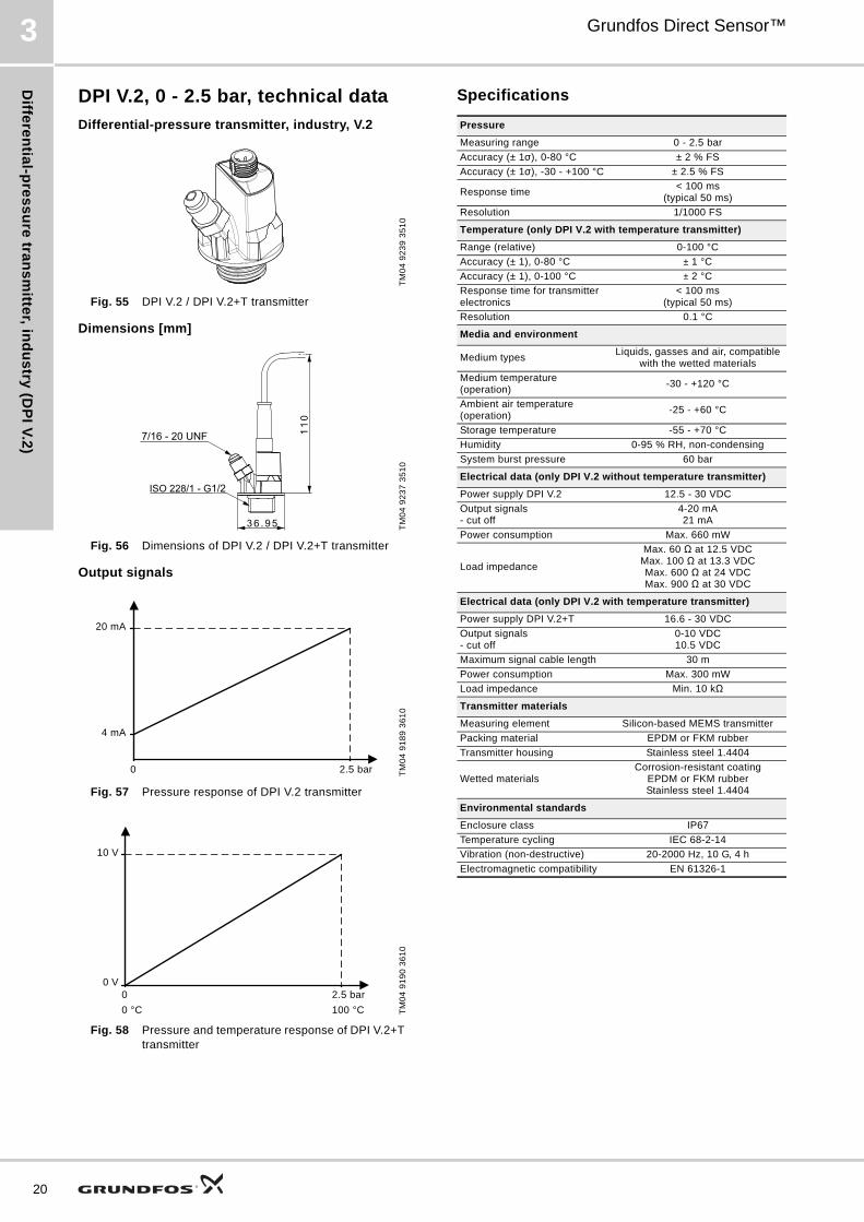
DPI V.2, 0 - 2.5 bar, technical data
Differential-pressure transmitter, industry, V.2
Fig. 55 DPI V.2 / DPI V.2+T transmitter
Dimensions [mm]
Fig. 56 Dimensions of DPI V.2 / DPI V.2+T transmitter
Output signals
Fig. 57 Pressure response of DPI V.2 transmitter
Fig. 58 Pressure and temperature response of DPI V.2+T transmitter
Specifications
TM
04
92
39
35
10
TM
04
92
37
35
10
TM
04
91
89
36
10
TM
04
91
90
36
10
7/16 - 20 UNF
1/2
0 2.5 bar
20 mA
4 mA
0 2.5 bar
10 V
0 °C 100 °C
0 V
Pressure
Measuring range 0 - 2.5 bar
Accuracy (± 1σ), 0-80 °C ± 2 % FS
Accuracy (± 1σ), -30 - +100 °C ± 2.5 % FS
Response time< 100 ms
(typical 50 ms)
Resolution 1/1000 FS
Temperature (only DPI V.2 with temperature transmitter)
Range (relative) 0-100 °C
Accuracy (± 1), 0-80 °C ± 1 °C
Accuracy (± 1), 0-100 °C ± 2 °C
Response time for transmitter electronics
< 100 ms(typical 50 ms)
Resolution 0.1 °C
Media and environment
Medium typesLiquids, gasses and air, compatible
with the wetted materials
Medium temperature (operation)
-30 - +120 °C
Ambient air temperature (operation)
-25 - +60 °C
Storage temperature -55 - +70 °C
Humidity 0-95 % RH, non-condensing
System burst pressure 60 bar
Electrical data (only DPI V.2 without temperature transmitter)
Power supply DPI V.2 12.5 - 30 VDC
Output signals - cut off
4-20 mA21 mA
Power consumption Max. 660 mW
Load impedance
Max. 60 Ω at 12.5 VDCMax. 100 Ω at 13.3 VDCMax. 600 Ω at 24 VDCMax. 900 Ω at 30 VDC
Electrical data (only DPI V.2 with temperature transmitter)
Power supply DPI V.2+T 16.6 - 30 VDC
Output signals - cut off
0-10 VDC10.5 VDC
Maximum signal cable length 30 m
Power consumption Max. 300 mW
Load impedance Min. 10 kΩ
Transmitter materials
Measuring element Silicon-based MEMS transmitter
Packing material EPDM or FKM rubber
Transmitter housing Stainless steel 1.4404
Wetted materialsCorrosion-resistant coating
EPDM or FKM rubberStainless steel 1.4404
Environmental standards
Enclosure class IP67
Temperature cycling IEC 68-2-14
Vibration (non-destructive) 20-2000 Hz, 10 G, 4 h
Electromagnetic compatibility EN 61326-1

Dif
fere
nti
al-
pre
ss
ure
tra
ns
mit
ter,
in
du
str
y (
DP
I V
.2)
Grundfos Direct Sensor™ 3
DPI V.2, 0 - 4.0 bar, technical data
Differential-pressure transmitter, industry, V.2
Fig. 59 DPI V.2 / DPI V.2+T transmitter
Dimensions [mm]
Fig. 60 Dimensions of DPI V.2 / DPI V.2+T transmitter
Output signals
Fig. 61 Pressure response of DPI V.2 transmitter
Fig. 62 Pressure and temperature response of DPI V.2+T transmitter
Specifications
TM
04
92
39
35
10
TM
04
92
37
35
10
TM
04
91
89
36
10
TM
04
91
90
36
10
7/16 - 20 UNF
1/2
0 4.0 bar
20 mA
4 mA
0 4.0 bar
10 V
0 °C 100 °C
0 V
Pressure
Measuring range 0 - 4.0 bar
Accuracy (± 1σ), 0-80 °C ± 2 % FS
Accuracy (± 1σ), -30 - +100 °C ± 2.5 % FS
Response time< 100 ms
(typical 50 ms)
Resolution 1/1000 FS
Temperature (only DPI V.2 with temperature transmitter)
Range (relative) 0-100 °C
Accuracy (± 1), 0-80 °C ± 1 °C
Accuracy (± 1), 0-100 °C ± 2 °C
Response time for transmitter electronics
< 100 ms(typical 50 ms)
Resolution 0.1 °C
Media and environment
Medium typesLiquids, gasses and air, compatible
with the wetted materials
Medium temperature (operation)
-30 - +120 °C
Ambient air temperature (operation)
-25 - +60 °C
Storage temperature -55 - +70 °C
Humidity 0-95 % RH, non-condensing
System burst pressure 60 bar
Electrical data (only DPI V.2 without temperature transmitter)
Power supply DPI V.2 12.5 - 30 VDC
Output signals - cut off
4-20 mA21 mA
Power consumption Max. 660 mW
Load impedance
Max. 60 Ω at 12.5 VDCMax. 100 Ω at 13.3 VDCMax. 600 Ω at 24 VDCMax. 900 Ω at 30 VDC
Electrical data (only DPI V.2 with temperature transmitter)
Power supply DPI V.2+T 16.6 - 30 VDC
Output signals - cut off
0-10 VDC10.5 VDC
Maximum signal cable length 30 m
Power consumption Max. 300 mW
Load impedance Min. 10 kΩ
Transmitter materials
Measuring element Silicon-based MEMS transmitter
Packing material EPDM or FKM rubber
Transmitter housing Stainless steel 1.4404
Wetted materialsCorrosion-resistant coating
EPDM or FKM rubberStainless steel 1.4404
Environmental standards
Enclosure class IP67
Temperature cycling IEC 68-2-14
Vibration (non-destructive) 20-2000 Hz, 10 G, 4 h
Electromagnetic compatibility EN 61326-1
21

Diffe
ren
tial-p
res
su
re tra
ns
mitte
r, ind
us
try (D
PI V
.2)
22
Grundfos Direct Sensor™3
DPI V.2, 0 - 6.0 bar, technical data
Differential-pressure transmitter, industry, V.2
Fig. 63 DPI V.2 / DPI V.2+T transmitter
Dimensions [mm]
Fig. 64 Dimensions of DPI V.2 / DPI V.2+T transmitter
Output signals
Fig. 65 Pressure response of DPI V.2 transmitter
Fig. 66 Pressure and temperature response of DPI V.2+T transmitter
Specifications
TM
04
92
39
35
10
TM
04
92
37
35
10
TM
04
91
89
36
10
TM
04
91
90
36
10
7/16 - 20 UNF
1/2
0 6.0 bar
20 mA
4 mA
0 6.0 bar
10 V
0 °C 100 °C
0 V
Pressure
Measuring range 0 - 6.0 bar
Accuracy (± 1σ), 0-80 °C ± 2 % FS
Accuracy (± 1σ), -30 - +100 °C ± 2.5 % FS
Response time< 100 ms
(typical 50 ms)
Resolution 1/1000 FS
Temperature (only DPI V.2 with temperature transmitter)
Range (relative) 0-100 °C
Accuracy (± 1), 0-80 °C ± 1 °C
Accuracy (± 1), 0-100 °C ± 2 °C
Response time for transmitter electronics
< 100 ms(typical 50 ms)
Resolution 0.1 °C
Media and environment
Medium typesLiquids, gasses and air, compatible
with the wetted materials
Medium temperature (operation)
-30 - +120 °C
Ambient air temperature (operation)
-25 - +60 °C
Storage temperature -55 - +70 °C
Humidity 0-95 % RH, non-condensing
System burst pressure 60 bar
Electrical data (only DPI V.2 without temperature transmitter)
Power supply DPI V.2 12.5 - 30 VDC
Output signals - cut off
4-20 mA21 mA
Power consumption Max. 660 mW
Load impedance
Max. 60 Ω at 12.5 VDCMax. 100 Ω at 13.3 VDCMax. 600 Ω at 24 VDCMax. 900 Ω at 30 VDC
Electrical data (only DPI V.2 with temperature transmitter)
Power supply DPI V.2+T 16.6 - 30 VDC
Output signals - cut off
0-10 VDC10.5 VDC
Maximum signal cable length 30 m
Power consumption Max. 300 mW
Load impedance Min. 10 kΩ
Transmitter materials
Measuring element Silicon-based MEMS transmitter
Packing material EPDM or FKM rubber
Transmitter housing Stainless steel 1.4404
Wetted materialsCorrosion-resistant coating
EPDM or FKM rubberStainless steel 1.4404
Environmental standards
Enclosure class IP67
Temperature cycling IEC 68-2-14
Vibration (non-destructive) 20-2000 Hz, 10 G, 4 h
Electromagnetic compatibility EN 61326-1

Dif
fere
nti
al-
pre
ss
ure
tra
ns
mit
ter,
in
du
str
y (
DP
I V
.2)
Grundfos Direct Sensor™ 3
DPI V.2, 0 - 10.0 bar, technical data
Differential-pressure transmitter, industry, V.2
Fig. 67 DPI V.2 / DPI V.2+T transmitter
Dimensions [mm]
Fig. 68 Dimensions of DPI V.2 / DPI V.2+T transmitter
Output signals
Fig. 69 Pressure response of DPI V.2 transmitter
Fig. 70 Pressure and temperature response of DPI V.2+T transmitter
Specifications
TM
04
92
39
35
10
TM
04
92
37
35
10
TM
04
91
89
36
10
TM
04
91
90
36
10
7/16 - 20 UNF
1/2
0 10.0 bar
20 mA
4 mA
0 10.0 bar
10 V
0 °C 100 °C
0 V
Pressure
Measuring range 0 - 10.0 bar
Accuracy (± 1σ), 0-80 °C ± 2 % FS
Accuracy (± 1σ), -30 - +100 °C ± 2.5 % FS
Response time< 100 ms
(typical 50 ms)
Resolution 1/1000 FS
Temperature (only DPI V.2 with temperature transmitter)
Range (relative) 0-100 °C
Accuracy (± 1), 0-80 °C ± 1 °C
Accuracy (± 1), 0-100 °C ± 2 °C
Response time for transmitter electronics
< 100 ms(typical 50 ms)
Resolution 0.1 °C
Media and environment
Medium typesLiquids, gasses and air, compatible
with the wetted materials
Medium temperature (operation)
-30 - +120 °C
Ambient air temperature (operation)
-25 - +60 °C
Storage temperature -55 - +70 °C
Humidity 0-95 % RH, non-condensing
System burst pressure 60 bar
Electrical data (only DPI V.2 without temperature transmitter)
Power supply DPI V.2 12.5 - 30 VDC
Output signals - cut off
4-20 mA21 mA
Power consumption Max. 660 mW
Load impedance
Max. 60 Ω at 12.5 VDCMax. 100 Ω at 13.3 VDCMax. 600 Ω at 24 VDCMax. 900 Ω at 30 VDC
Electrical data (only DPI V.2 with temperature transmitter)
Power supply DPI V.2+T 16.6 - 30 VDC
Output signals - cut off
0-10 VDC10.5 VDC
Maximum signal cable length 30 m
Power consumption Max. 300 mW
Load impedance Min. 10 kΩ
Transmitter materials
Measuring element Silicon-based MEMS transmitter
Packing material EPDM or FKM rubber
Transmitter housing Stainless steel 1.4404
Wetted materialsCorrosion-resistant coating
EPDM or FKM rubberStainless steel 1.4404
Environmental standards
Enclosure class IP67
Temperature cycling IEC 68-2-14
Vibration (non-destructive) 20-2000 Hz, 10 G, 4 h
Electromagnetic compatibility EN 61326-1
23

Diffe
ren
tial-p
res
su
re tra
ns
mitte
r, ind
us
try (D
PI V
.2)
24
Grundfos Direct Sensor™3
DPI V.2, 0 - 16.0 bar, technical data
Differential-pressure transmitter, industry, V.2
Fig. 71 DPI V.2 / DPI V.2+T transmitter
Dimensions [mm]
Fig. 72 Dimensions of DPI V.2 / DPI V.2+T transmitter
Output signals
Fig. 73 Pressure response of DPI V.2 transmitter
Fig. 74 Pressure and temperature response of DPI V.2+T transmitter
Specifications
TM
04
92
39
35
10
TM
04
92
37
35
10
TM
04
91
89
36
10
TM
04
91
90
36
10
7/16 - 20 UNF
1/2
0 16.0 bar
20 mA
4 mA
0 16.0 bar
10 V
0 °C 100 °C
0 V
Pressure
Measuring range 0 - 16.0 bar
Accuracy (± 1σ), 0-80 °C ± 2 % FS
Accuracy (± 1σ), -30 - +100 °C ± 2.5 % FS
Response time< 100 ms
(typical 50 ms)
Resolution 1/1000 FS
Temperature (only DPI V.2 with temperature transmitter)
Range (relative) 0-100 °C
Accuracy (± 1), 0-80 °C ± 1 °C
Accuracy (± 1), 0-100 °C ± 2 °C
Response time for transmitter electronics
< 100 ms(typical 50 ms)
Resolution 0.1 °C
Media and environment
Medium typesLiquids, gasses and air, compatible
with the wetted materials
Medium temperature (operation)
-30 - +120 °C
Ambient air temperature (operation)
-25 - +60 °C
Storage temperature -55 - +70 °C
Humidity 0-95 % RH, non-condensing
System burst pressure 60 bar
Electrical data (only DPI V.2 without temperature transmitter)
Power supply DPI V.2 12.5 - 30 VDC
Output signals - cut off
4-20 mA21 mA
Power consumption Max. 660 mW
Load impedance
Max. 60 Ω at 12.5 VDCMax. 100 Ω at 13.3 VDCMax. 600 Ω at 24 VDCMax. 900 Ω at 30 VDC
Electrical data (only DPI V.2 with temperature transmitter)
Power supply DPI V.2+T 16.6 - 30 VDC
Output signals - cut off
0-10 VDC10.5 VDC
Maximum signal cable length 30 m
Power consumption Max. 300 mW
Load impedance Min. 10 kΩ
Transmitter materials
Measuring element Silicon-based MEMS transmitter
Packing material EPDM or FKM rubber
Transmitter housing Stainless steel 1.4404
Wetted materialsCorrosion-resistant coating
EPDM or FKM rubberStainless steel 1.4404
Environmental standards
Enclosure class IP67
Temperature cycling IEC 68-2-14
Vibration (non-destructive) 20-2000 Hz, 10 G, 4 h
Electromagnetic compatibility EN 61326-1

Dif
fere
nti
al-
pre
ss
ure
tra
ns
mit
ter,
in
du
str
y (
DP
I)
Grundfos Direct Sensor™ 4
4. Differential-pressure transmitter, industry (DPI)
DPI general data
Differential-pressure transmitter, industry
Fig. 75 DPI transmitter
Technical overview Grundfos Direct Sensors™, type DPI, is a series of industrial strength differential-pressure transmitters. The DPI transmitters are compatible with wet, aggressive media and are available for differential-pressure ranges from 0 - 0.6 to 0 - 10.0 bar.
The DPI transmitters use MEMS sensing technology in combination with a new packaging concept with corrosion-resistant coating on the MEMS sensing element. This makes the DPI transmitters very robust and ideal for pump integration and monitoring in harsh environments.
Applications• Pumps and pump control systems
• filters (monitoring)
• cooling and temperature control systems
• water treatment systems
• boiler control systems
• renewable energy systems
• heat exchangers (monitoring of fouling).
Features• Differential-pressure ranges of 0 - 0.6, 0 - 1.0,
0 -1.2, 0 - 1.6, 0 - 2.5, 0 - 4.0, 0 - 6.0 and 0 - 10.0 bar
• designed for harsh environments
• analog output signal
• compact and proven design
• MEMS sensing technology
• approved for the EU, US and Canadian markets.
Benefits• Compatible with wet, aggressive media
• accurate, linearised output signal
• cost-effective and robust design.
Type keyThe transmitter is labelled with a type designation.
Electrical connections
Fig. 76 Electrical connections
TM
04
47
38
05
09
96561232 - XX - XXX XXXXX
Product number
Version
Production code (year and week)
Consecutive number
TM
04
91
91
36
10
Pin Description Colour
1Test conductor (can be cut off during mounting).Do not connect this conductor to the power supply.
White
2 Signal conductor Green
3 GND (earth conductor) Yellow
4 12-30 V supply voltage Brown
A
4321
PE
25
Diffe
ren
tial-p
res
su
re tra
ns
mitte
r, ind
us
try (D
PI)
26
Grundfos Direct Sensor™4
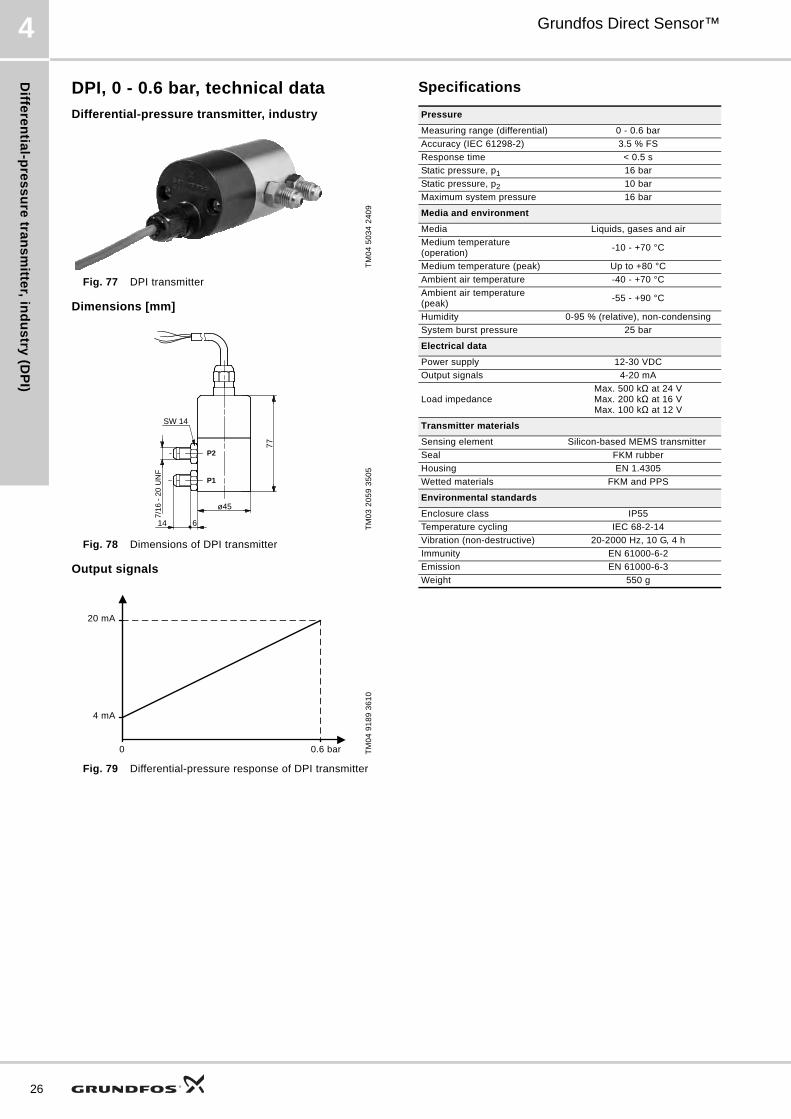
DPI, 0 - 0.6 bar, technical data
Differential-pressure transmitter, industry
Fig. 77 DPI transmitter
Dimensions [mm]
Fig. 78 Dimensions of DPI transmitter
Output signals
Fig. 79 Differential-pressure response of DPI transmitter
Specifications
TM
04
50
34
24
09
TM
03
20
59
35
05
TM
04
91
89
36
10
7/16
- 2
0 U
NF
ø45
77
614
SW 14
P2
P1
0 0.6 bar
20 mA
4 mA
Pressure
Measuring range (differential) 0 - 0.6 bar
Accuracy (IEC 61298-2) 3.5 % FS
Response time < 0.5 s
Static pressure, p1 16 bar
Static pressure, p2 10 bar
Maximum system pressure 16 bar
Media and environment
Media Liquids, gases and air
Medium temperature (operation)
-10 - +70 °C
Medium temperature (peak) Up to +80 °C
Ambient air temperature -40 - +70 °C
Ambient air temperature (peak)
-55 - +90 °C
Humidity 0-95 % (relative), non-condensing
System burst pressure 25 bar
Electrical data
Power supply 12-30 VDC
Output signals 4-20 mA
Load impedanceMax. 500 kΩ at 24 VMax. 200 kΩ at 16 VMax. 100 kΩ at 12 V
Transmitter materials
Sensing element Silicon-based MEMS transmitter
Seal FKM rubber
Housing EN 1.4305
Wetted materials FKM and PPS
Environmental standards
Enclosure class IP55
Temperature cycling IEC 68-2-14
Vibration (non-destructive) 20-2000 Hz, 10 G, 4 h
Immunity EN 61000-6-2
Emission EN 61000-6-3
Weight 550 g

Dif
fere
nti
al-
pre
ss
ure
tra
ns
mit
ter,
in
du
str
y (
DP
I)
Grundfos Direct Sensor™ 4
DPI, 0 - 1.0 bar, technical data
Differential-pressure transmitter, industry
Fig. 80 DPI transmitter
Dimensions [mm]
Fig. 81 Dimensions of DPI transmitter
Output signals
Fig. 82 Differential-pressure response of DPI transmitter
Specifications
TM
04
50
34
24
09
TM
03
20
59
35
05
TM
04
91
89
36
10
7/16
- 2
0 U
NF
ø45
77
614
SW 14
P2
P1
0 1.0 bar
20 mA
4 mA
Pressure
Measuring range (differential) 0 - 1.0 bar
Accuracy (IEC 61298-2) 2 % FS
Response time < 0.5 s
Static pressure, p1 16 bar
Static pressure, p2 10 bar
Maximum system pressure 16 bar
Media and environment
Media Liquids, gases and air
Medium temperature (operation)
-10 - +70 °C
Medium temperature (peak) Up to +80 °C
Ambient air temperature -40 - +70 °C
Ambient air temperature (peak)
-55 - +90 °C
Humidity 0-95 % (relative), non-condensing
System burst pressure 25 bar
Electrical data
Power supply 12-30 VDC
Output signals 4-20 mA
Load impedanceMax. 500 kΩ at 24 VMax. 200 kΩ at 16 VMax. 100 kΩ at 12 V
Transmitter materials
Sensing element Silicon-based MEMS transmitter
Seal FKM rubber
Housing EN 1.4305
Wetted materials FKM and PPS
Environmental standards
Enclosure class IP55
Temperature cycling IEC 68-2-14
Vibration (non-destructive) 20-2000 Hz, 10 G, 4 h
Immunity EN 61000-6-2
Emission EN 61000-6-3
Weight 550 g
27

Diffe
ren
tial-p
res
su
re tra
ns
mitte
r, ind
us
try (D
PI)
28
Grundfos Direct Sensor™4
DPI, 0 - 1.2 bar, technical data
Differential-pressure transmitter, industry
Fig. 83 DPI transmitter
Dimensions [mm]
Fig. 84 Dimensions of DPI transmitter
Output signals
Fig. 85 Differential-pressure response of DPI transmitter
Specifications
TM
04
50
34
24
09
TM
03
20
59
35
05
TM
04
91
89
36
10
7/16
- 2
0 U
NF
ø45
77
614
SW 14
P2
P1
0 1.2 bar
20 mA
4 mA
Pressure
Measuring range (differential) 0 - 1.2 bar
Accuracy (IEC 61298-2) 2 % FS
Response time < 0.5 s
Static pressure, p1 16 bar
Static pressure, p2 10 bar
Maximum system pressure 16 bar
Media and environment
Media Liquids, gases and air
Medium temperature (operation)
-10 - +70 °C
Medium temperature (peak) Up to +80 °C
Ambient air temperature -40 - +70 °C
Ambient air temperature (peak)
-55 - +90 °C
Humidity 0-95 % (relative), non-condensing
System burst pressure 25 bar
Electrical data
Power supply 12-30 VDC
Output signals 4-20 mA
Load impedanceMax. 500 kΩ at 24 VMax. 200 kΩ at 16 VMax. 100 kΩ at 12 V
Transmitter materials
Sensing element Silicon-based MEMS transmitter
Seal FKM rubber
Housing EN 1.4305
Wetted materials FKM and PPS
Environmental standards
Enclosure class IP55
Temperature cycling IEC 68-2-14
Vibration (non-destructive) 20-2000 Hz, 10 G, 4 h
Immunity EN 61000-6-2
Emission EN 61000-6-3
Weight 550 g

Dif
fere
nti
al-
pre
ss
ure
tra
ns
mit
ter,
in
du
str
y (
DP
I)
Grundfos Direct Sensor™ 4
DPI, 0 - 1.6 bar, technical data
Differential-pressure transmitter, industry
Fig. 86 DPI transmitter
Dimensions [mm]
Fig. 87 Dimensions of DPI transmitter
Output signals
Fig. 88 Differential-pressure response of DPI transmitter
Specifications
TM
04
50
34
24
09
TM
03
20
59
35
05
TM
04
91
89
36
10
7/16
- 2
0 U
NF
ø45
77
614
SW 14
P2
P1
0 1.6 bar
20 mA
4 mA
Pressure
Measuring range (differential) 0 - 1.6 bar
Accuracy (IEC 61298-2) 2 % FS
Response time < 0.5 s
Static pressure, p1 16 bar
Static pressure, p2 10 bar
Maximum system pressure 16 bar
Media and environment
Media Liquids, gases and air
Medium temperature (operation)
-10 - +70 °C
Medium temperature (peak) Up to +80 °C
Ambient air temperature -40 - +70 °C
Ambient air temperature (peak)
-55 - +90 °C
Humidity 0-95 % (relative), non-condensing
System burst pressure 25 bar
Electrical data
Power supply 12-30 VDC
Output signals 4-20 mA
Load impedanceMax. 500 kΩ at 24 VMax. 200 kΩ at 16 VMax. 100 kΩ at 12 V
Transmitter materials
Sensing element Silicon-based MEMS transmitter
Seal FKM rubber
Housing EN 1.4305
Wetted materials FKM and PPS
Environmental standards
Enclosure class IP55
Temperature cycling IEC 68-2-14
Vibration (non-destructive) 20-2000 Hz, 10 G, 4 h
Immunity EN 61000-6-2
Emission EN 61000-6-3
Weight 550 g
29

Diffe
ren
tial-p
res
su
re tra
ns
mitte
r, ind
us
try (D
PI)
30
Grundfos Direct Sensor™4
DPI, 0 - 2.5 bar, technical data
Differential-pressure transmitter, industry
Fig. 89 DPI transmitter
Dimensions [mm]
Fig. 90 Dimensions of DPI transmitter
Output signals
Fig. 91 Differential-pressure response of DPI transmitter
Specifications
TM
04
50
34
24
09
TM
03
20
59
35
05
TM
04
91
89
36
10
7/16
- 2
0 U
NF
ø45
77
614
SW 14
P2
P1
0 2.5 bar
20 mA
4 mA
Pressure
Measuring range (differential) 0 - 2.5 bar
Accuracy (IEC 61298-2) 2 % FS
Response time < 0.5 s
Static pressure, p1 16 bar
Static pressure, p2 10 bar
Maximum system pressure 16 bar
Media and environment
Media Liquids, gases and air
Medium temperature (operation)
-10 - +70 °C
Medium temperature (peak) Up to +80 °C
Ambient air temperature -40 - +70 °C
Ambient air temperature (peak)
-55 - +90 °C
Humidity 0-95 % (relative), non-condensing
System burst pressure 25 bar
Electrical data
Power supply 12-30 VDC
Output signals 4-20 mA
Load impedanceMax. 500 kΩ at 24 VMax. 200 kΩ at 16 VMax. 100 kΩ at 12 V
Transmitter materials
Sensing element Silicon-based MEMS transmitter
Seal FKM rubber
Housing EN 1.4305
Wetted materials FKM and PPS
Environmental standards
Enclosure class IP55
Temperature cycling IEC 68-2-14
Vibration (non-destructive) 20-2000 Hz, 10 G, 4 h
Immunity EN 61000-6-2
Emission EN 61000-6-3
Weight 550 g

Dif
fere
nti
al-
pre
ss
ure
tra
ns
mit
ter,
in
du
str
y (
DP
I)
Grundfos Direct Sensor™ 4
DPI, 0 - 4.0 bar, technical data
Differential-pressure transmitter, industry
Fig. 92 DPI transmitter
Dimensions [mm]
Fig. 93 Dimensions of DPI transmitter
Output signals
Fig. 94 Differential-pressure response of DPI transmitter
Specifications
TM
04
50
34
24
09
TM
03
20
59
35
05
TM
04
91
89
36
10
7/16
- 2
0 U
NF
ø45
77
614
SW 14
P2
P1
0 4.0 bar
20 mA
4 mA
Pressure
Measuring range (differential) 0 - 4.0 bar
Accuracy (IEC 61298-2) 2 % FS
Response time < 0.5 s
Static pressure, p1 16 bar
Static pressure, p2 10 bar
Maximum system pressure 16 bar
Media and environment
Media Liquids, gases and air
Medium temperature (operation)
-10 - +70 °C
Medium temperature (peak) Up to +80 °C
Ambient air temperature -40 - +70 °C
Ambient air temperature (peak)
-55 - +90 °C
Humidity 0-95 % (relative), non-condensing
System burst pressure 25 bar
Electrical data
Power supply 12-30 VDC
Output signals 4-20 mA
Load impedanceMax. 500 kΩ at 24 VMax. 200 kΩ at 16 VMax. 100 kΩ at 12 V
Transmitter materials
Sensing element Silicon-based MEMS transmitter
Seal FKM rubber
Housing EN 1.4305
Wetted materials FKM and PPS
Environmental standards
Enclosure class IP55
Temperature cycling IEC 68-2-14
Vibration (non-destructive) 20-2000 Hz, 10 G, 4 h
Immunity EN 61000-6-2
Emission EN 61000-6-3
Weight 550 g
31

Diffe
ren
tial-p
res
su
re tra
ns
mitte
r, ind
us
try (D
PI)
32
Grundfos Direct Sensor™4
DPI, 0 - 6.0 bar, technical data
Differential-pressure transmitter, industry
Fig. 95 DPI transmitter
Dimensions [mm]
Fig. 96 Dimensions of DPI transmitter
Output signals
Fig. 97 Differential-pressure response of DPI transmitter
Specifications
TM
04
50
34
24
09
TM
03
20
59
35
05
TM
04
91
89
36
10
7/16
- 2
0 U
NF
ø45
77
614
SW 14
P2
P1
0 6.0 bar
20 mA
4 mA
Pressure
Measuring range (differential) 0 - 6.0 bar
Accuracy (IEC 61298-2) 2 % FS
Response time < 0.5 s
Static pressure, p1 16 bar
Static pressure, p2 10 bar
Maximum system pressure 16 bar
Media and environment
Media Liquids, gases and air
Medium temperature (operation)
-10 - +70 °C
Medium temperature (peak) Up to +80 °C
Ambient air temperature -40 - +70 °C
Ambient air temperature (peak)
-55 - +90 °C
Humidity 0-95 % (relative), non-condensing
System burst pressure 25 bar
Electrical data
Power supply 12-30 VDC
Output signals 4-20 mA
Load impedanceMax. 500 kΩ at 24 VMax. 200 kΩ at 16 VMax. 100 kΩ at 12 V
Transmitter materials
Sensing element Silicon-based MEMS transmitter
Seal FKM rubber
Housing EN 1.4305
Wetted materials FKM and PPS
Environmental standards
Enclosure class IP55
Temperature cycling IEC 68-2-14
Vibration (non-destructive) 20-2000 Hz, 10 G, 4 h
Immunity EN 61000-6-2
Emission EN 61000-6-3
Weight 550 g

Dif
fere
nti
al-
pre
ss
ure
tra
ns
mit
ter,
in
du
str
y (
DP
I)
Grundfos Direct Sensor™ 4
DPI, 0 - 10.0 bar, technical data
Differential-pressure transmitter, industry
Fig. 98 DPI transmitter
Dimensions [mm]
Fig. 99 Dimensions of DPI transmitter
Output signals
Fig. 100 Differential-pressure response of DPI transmitter
Specifications
TM
04
50
34
24
09
TM
03
20
59
35
05
TM
04
91
89
36
10
7/16
- 2
0 U
NF
ø45
77
614
SW 14
P2
P1
0 10.0 bar
20 mA
4 mA
Pressure
Measuring range (differential) 0 - 10.0 bar
Accuracy (IEC 61298-2) 2 % FS
Response time < 0.5 s
Static pressure, p1 16 bar
Static pressure, p2 10 bar
Maximum system pressure 16 bar
Media and environment
Media Liquids, gases and air
Medium temperature (operation)
-10 - +70 °C
Medium temperature (peak) Up to +80 °C
Ambient air temperature -40 - +70 °C
Ambient air temperature (peak)
-55 - +90 °C
Humidity 0-95 % (relative), non-condensing
System burst pressure 25 bar
Electrical data
Power supply 12-30 VDC
Output signals 4-20 mA
Load impedanceMax. 500 kΩ at 24 VMax. 200 kΩ at 16 VMax. 100 kΩ at 12 V
Transmitter materials
Sensing element Silicon-based MEMS transmitter
Seal FKM rubber
Housing EN 1.4305
Wetted materials FKM and PPS
Environmental standards
Enclosure class IP55
Temperature cycling IEC 68-2-14
Vibration (non-destructive) 20-2000 Hz, 10 G, 4 h
Immunity EN 61000-6-2
Emission EN 61000-6-3
Weight 550 g
33
Re
lativ
e-p
res
su
re tra
ns
mitte
r, dig
ital (R
PD
)
34
Grundfos Direct Sensor™5
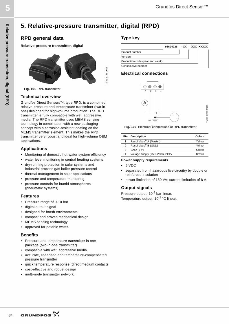
5. Relative-pressure transmitter, digital (RPD)
RPD general data
Relative-pressure transmitter, digital
Fig. 101 RPD transmitter
Technical overviewGrundfos Direct Sensors™, type RPD, is a combined relative-pressure and temperature transmitter (two-in-one) designed for high-volume production. The RPD transmitter is fully compatible with wet, aggressive media. The RPD transmitter uses MEMS sensing technology in combination with a new packaging concept with a corrosion-resistant coating on the MEMS transmitter element. This makes the RPD transmitter very robust and ideal for high-volume OEM applications.
Applications• Monitoring of domestic hot-water system efficiency
• water level monitoring in central heating systems
• dry-running protection in solar systems and industrial process gas boiler pressure control
• thermal management in solar applications
• pressure and temperature monitoring
• pressure controls for humid atmospheres (pneumatic systems).
Features• Pressure range of 0-10 bar
• digital output signal
• designed for harsh environments
• compact and proven mechanical design
• MEMS sensing technology
• approved for potable water.
Benefits• Pressure and temperature transmitter in one
package (two-in-one transmitter)
• compatible with wet, aggressive media
• accurate, linearised and temperature-compensated pressure transmitter
• quick temperature response (direct medium contact)
• cost-effective and robust design
• multi-node transmitter network.
Type key
Electrical connections
Fig. 102 Electrical connections of RPD transmitter
Power supply requirements
• 5 VDC
• separated from hazardous live circuitry by double or reinforced insulation
• power limitation of 150 VA; current limitation of 8 A.
Output signalsPressure output: 10-2 bar linear.
Temperature output: 10-2 °C linear.
TM
03
81
38
06
08
96694226 - XX - XXX XXXXX
Product number
Version
Production code (year and week)
Consecutive number
TM
03
82
03
19
08
Pin Description Colour
1 Resol Vbus® A (Master) Yellow
2 Resol Vbus® B (GND) White
3 GND (0 V) Green
4 Voltage supply (+5.5 VDC), PELV Brown
A
4321
PE

Re
lati
ve
-pre
ss
ure
tra
ns
mit
ter,
dig
ita
l (R
PD
)
Grundfos Direct Sensor™ 5
RPD, 0-10 bar, technical data
Dimensions [mm]
Fig. 103 Dimensions of RPD
Specifications
* Specification valid for water media only.
TM
03
81
36
06
07
Pressure
Measuring range (relative) 0-10 bar
Accuracy (± 1σ), 0-100 °C, water
± 2 % FS
Accuracy (± 1σ), 20-80 °C, Tyfocur LS
± 3 % FS
Pressure refresh rate 250 ms
Resolution 20 mbar
Temperature
Measuring range 0-120 °C
Accuracy (± 1σ), 25-80 °C ± 1 °C
Accuracy (± 1σ), 0-100 °C ± 3 °C
Accuracy 100-120 °C Reading/indication only
Temperature refresh rate 250 ms
Response time < 4 s (depending on mounting)
Resolution 0.4 °C
Media and environment
Medium types Liquids
Medium temperature (operation)
0-100 °C
Medium temperature (peak) -25 - +120 °C
Ambient air temperature (operation)
-25 - +60 °C
Ambient air temperature (peak)
-55 - +90 °C
Humidity 0-95 % RH, non-condensing
System burst pressure > 30 bar
Electrical data
Power supply5.5 VDC (± 5 %)
Grounding of transmitter supply recommended (PELV)
Output signals Resol VBus® Protocol version 3
Pressure signal Resol VBus® Protocol version 3
Temperature signal Resol VBus® Protocol version 3
Resol VBus® refresh rate 250 ms
Data rate 9600 baud
Power consumption transmitter
< 50 mW
Power for Resol VBus® operation
See Resol VBus® Protocol version 3
Pin configurations See fig. 102
Recommended female connector
Molex No 5557-04R www.molex.com
Transmitter materials
Sensing element Silicon-based MEMS transmitter
Seal (transmitter to housing) EPDM rubber
Housing Composites (PPS, PA66)
Vortex tube PPA 40-GF
Wetted materialsCorrosion-resistant coating, EPDM,
PPS
Environmental standards
Enclosure class IP44 (non-overmoulded IP20)
Temperature cycling IEC 68-2-14
Vibration (non-destructive) 20-2000 Hz, 10 G, 4 h
Electromagnetic compatibility EN 61326-1
Approved for potable water Transmitter/insert => OK
Dimensions
Sensing element 47 x 40 x 20 mm. See fig. 103
35

Re
lativ
e-p
res
su
re tra
ns
mitte
r, sta
nd
ard
(RP
S)
36
Grundfos Direct Sensor™6
6. Relative-pressure transmitter, standard (RPS)
RPS general data
Relative-pressure transmitter, standard
Fig. 104 RPS transmitter
Technical overviewGrundfos Direct Sensors™, type RPS, is a series of combined pressure and temperature transmitters (two-in-one) designed for high-volume production. The RPS transmitters are fully compatible with wet, aggressive media and are available for pressure ranges from 0 - 0.6 to 0 - 10.0 bar (relative pressure).
The RPS transmitters use MEMS sensing technology in combination with a new packaging concept with corrosion-resistant coating on the MEMS transmitter element. This makes the RPS transmitters very robust and ideal for high-volume OEM applications.
Applications• Monitoring of domestic hot-water system efficiency
• water level monitoring in central heating systems
• dry-running protection in solar systems and gas boilers
• pressure and temperature monitoring.
Features• Pressure ranges of 0 - 0.6, 0 - 1.0, 0 - 1.6, 0 - 2.5,
0 - 4.0, 0 - 6.0 and 0 - 10.0 bar
• voltage output (ratiometric, ideal for use with microcontroller)
• compact and proven mechanical design
• approved for potable water, i.e. WRAS, KTW, W270, ACS.
Benefits• Pressure and temperature transmitter in one
package (two-in-one transmitter)
• compatible with wet, aggressive media
• accurate, linearised and temperature-compensated pressure transmitter
• quick temperature response (direct medium contact).
Type keyThe transmitter is labelled with a type designation.
Electrical connections
Fig. 105 Electrical connections
Power supply requirements
• 5 VDC
• separated from hazardous live circuitry by double or reinforced insulation
• power limitation of 150 VA; current limitation of 8 A.
Options
Fig. 106 Transmitter options
TM
03
81
38
06
07
96XXXXXX - XX - XXX XXXXX
Product number
Version
Production code (year and week)
Consecutive number
TM
05
22
53
47
11
Pin Description Colour
1 Temperature signal (0.5 to 3.5 V relative to pin 3) Yellow
2 Pressure signal (0.5 to 3.5 V relative to pin 3) White
3 GND (0 V) Green
4 Voltage supply (+5 VDC), PELV Brown
TM
03
81
39
06
07
Pos. Description
A 1/2'' nipple, stainless steel (316L) or 3/8" composite
B Overmoulded or simple connector
V
V
4321
PE
Pipe system
A
B

Re
lati
ve
-pre
ss
ure
tra
ns
mit
ter,
sta
nd
ard
(R
PS
)
Grundfos Direct Sensor™ 6
RPS, 0 - 0.6 bar, technical data
Relative-pressure transmitter, standard
Fig. 107 RPS transmitter
Dimensions [mm]
Fig. 108 Dimensions of RPS transmitter
Output signals
Fig. 109 Pressure response of RPS transmitter
Fig. 110 Temperature response of RPS transmitter
Specifications
TM
05
22
54
47
11T
M0
3 8
13
6 0
60
7T
M0
3 8
14
1 0
60
7T
M0
3 8
14
9 0
60
7
Pressure
Measuring range (relative) 0 - 0.6 bar
Accuracy (± 1σ), 25-80 °C ± 2 % FS
Accuracy (± 1σ), 0-100 °C ± 3 % FS
Response time < 0.5 s
Resolution 5 mbar
Temperature
Measuring range 0-100 °C
Accuracy (± 1σ), 25-80 °C ± 1 °C
Accuracy (± 1σ), 0-100 °C ± 2 °C
Response time (63.3 % at flow velocity > 2 m/s)
< 1.5 s
Resolution 0.5 °C
Media and environment
Media Liquids
Medium temperature (operation)
0-100 °C
Medium temperature (peak) -25 - +120 °C, non-freezing
Ambient air temperature (operation)
-25 - +60 °C
Ambient air temperature (peak) -55 - +90 °C
Humidity 0-95 % (relative), non-condensing
System burst pressure > 30 bar
Electrical data
Power supply5 VDC (± 5 %)
Grounding of transmitter supply recommended.
Output signals Ratiometric
Pressure signal 0.5 - 3.5 V
Temperature signal 0.5 - 3.5 V
Power consumption < 50 mW
Load impedance > 10 kΩTransmitter materials
Transmitter Silicon-based MEMS transmitter
Seal (transmitter to housing) EPDM rubber
Housing Composites (PPS)
Wetted materialsCorrosion-resistant coating, EPDM,
PPS
Environmental standards
Enclosure class IP44 (non-overmoulded IP20)
Temperature cycling IEC 68-2-14
Vibration (non-destructive) 20-2000 Hz, 10 G, 4 h
Electromagnetic compatibility EN 61326-1
Dimensions
Transmitter 47 x 40 x 20 mm
37

Re
lativ
e-p
res
su
re tra
ns
mitte
r, sta
nd
ard
(RP
S)
38
Grundfos Direct Sensor™6
RPS, 0 - 1.0 bar, technical data
Relative-pressure transmitter, standard
Fig. 111 RPS transmitter
Dimensions [mm]
Fig. 112 Dimensions of RPS transmitter
Output signals
Fig. 113 Pressure response of RPS transmitter
Fig. 114 Temperature response of RPS transmitter
Specifications
TM
05
22
54
47
11T
M0
3 8
13
6 0
60
7T
M0
3 8
14
2 0
60
7T
M0
3 8
14
9 0
60
7
Pressure
Measuring range (relative) 0 - 1.0 bar
Accuracy (± 1σ), 25-80 °C ± 2 % FS
Accuracy (± 1σ), 0-100 °C ± 3 % FS
Response time < 0.5 s
Resolution 5 mbar
Temperature
Measuring range 0-100 °C
Accuracy (± 1σ), 25-80 °C ± 1 °C
Accuracy (± 1σ), 0-100 °C ± 2 °C
Response time (63.3 % at flow velocity > 2 m/s)
< 1.5 s
Resolution 0.5 °C
Media and environment
Media Liquids
Medium temperature (operation)
0-100 °C
Medium temperature (peak) -25 - +120 °C, non-freezing
Ambient air temperature (operation)
-25 - +60 °C
Ambient air temperature (peak) -55 - +90 °C
Humidity 0-95 % (relative), non-condensing
System burst pressure > 30 bar
Electrical data
Power supply5 VDC (± 5 %)
Grounding of transmitter supply recommended.
Output signals Ratiometric
Pressure signal 0.5 - 3.5 V
Temperature signal 0.5 - 3.5 V
Power consumption < 50 mW
Load impedance > 10 kΩTransmitter materials
Transmitter Silicon-based MEMS transmitter
Seal (transmitter to housing) EPDM rubber
Housing Composites (PPS)
Wetted materialsCorrosion-resistant coating, EPDM,
PPS
Environmental standards
Enclosure class IP44 (non-overmoulded IP20)
Temperature cycling IEC 68-2-14
Vibration (non-destructive) 20-2000 Hz, 10 G, 4 h
Electromagnetic compatibility EN 61326-1
Dimensions
Transmitter 47 x 40 x 20 mm

Re
lati
ve
-pre
ss
ure
tra
ns
mit
ter,
sta
nd
ard
(R
PS
)
Grundfos Direct Sensor™ 6
RPS, 0 - 1.6 bar, technical data
Relative-pressure transmitter, standard
Fig. 115 RPS transmitter
Dimensions [mm]
Fig. 116 Dimensions of RPS transmitter
Output signals
Fig. 117 Pressure response of RPS transmitter
Fig. 118 Temperature response of RPS transmitter
Specifications
TM
05
22
54
47
11T
M0
3 8
13
6 0
60
7T
M0
3 8
14
3 0
60
7T
M0
3 8
14
9 0
60
7
Pressure
Measuring range (relative) 0 - 1.6 bar
Accuracy (± 1σ), 25-80 °C ± 1.5 % FS
Accuracy (± 1σ), 0-100 °C ± 2.5 % FS
Response time < 0.5 s
Resolution 5 mbar
Temperature
Measuring range 0-100 °C
Accuracy (± 1σ), 25-80 °C ± 1 °C
Accuracy (± 1σ), 0-100 °C ± 2 °C
Response time (63.3 % at flow velocity > 2 m/s)
< 1.5 s
Resolution 0.5 °C
Media and environment
Media Liquids
Medium temperature (operation)
0-100 °C
Medium temperature (peak) -25 - +120 °C, non-freezing
Ambient air temperature (operation)
-25 - +60 °C
Ambient air temperature (peak) -55 - +90 °C
Relative humidity 0-95 %, non-condensing
System burst pressure > 30 bar
Electrical interface
Power supply5 VDC (± 5 %)
Grounding of transmitter supply recommended.
Output signals Ratiometric
Pressure signal 0.5 - 3.5 V
Temperature signal 0.5 - 3.5 V
Power consumption < 50 mW
Load impedance > 10 kΩTransmitter materials
Transmitter Silicon-based MEMS transmitter
Seal (transmitter to housing) EPDM rubber
Housing Composites (PPS)
Wetted materialsCorrosion-resistant coating, EPDM,
PPS
Environmental standards
Enclosure class IP44 (non-overmoulded IP20)
Temperature cycling IEC 68-2-14
Vibration (non-destructive) 20-2000 Hz, 10 G, 4 h
Electromagnetic compatibility EN 61326-1
Dimensions
Transmitter 47 x 40 x 20 mm
39

Re
lativ
e-p
res
su
re tra
ns
mitte
r, sta
nd
ard
(RP
S)
40
Grundfos Direct Sensor™6
RPS, 0 - 2.5 bar, technical data
Relative-pressure transmitter, standard
Fig. 119 RPS transmitter
Dimensions [mm]
Fig. 120 Dimensions of RPS transmitter
Output signals
Fig. 121 Pressure response of RPS transmitter
Fig. 122 Temperature response of RPS transmitter
Specifications
TM
05
22
54
47
11T
M0
3 8
13
6 0
60
7T
M0
3 8
14
4 0
60
7T
M0
3 8
14
9 0
60
7
Pressure
Measuring range (relative) 0 - 2.5 bar
Accuracy (± 1σ), 25-80 °C ± 1.5 % FS
Accuracy (± 1σ), 0-100 °C ± 2 % FS
Response time < 0.5 s
Resolution 20 mbar
Temperature
Measuring range 0-100 °C
Accuracy (± 1σ), 25-80 °C ± 1 °C
Accuracy (± 1σ), 0-100 °C ± 2.5 °C
Response time (63.3 % at flow velocity > 2 m/s)
< 1.5 s
Resolution 0.5 °C
Media and environment
Media Liquids
Medium temperature (operating)
0-100 °C
Medium temperature (peak) -25 - +120 °C, non-freezing
Ambient air temperature (operating)
-25 - +60 °C
Ambient air temperature (peak) -55 - +90 °C
Humidity 0-95 % (relative), non-condensing
System burst pressure > 30 bar
Electrical data
Power supply5 VDC (± 5 %)
Grounding of transmitter supply recommended.
Output signals Ratiometric
Pressure signal 0.5 - 3.5 V
Temperature signal 0.5 - 3.5 V
Power consumption < 50 mW
Load impedance > 10 kΩTransmitter materials
Transmitter Silicon-based MEMS transmitter
Seal (transmitter to housing) EPDM rubber
Housing Composites (PPS)
Wetted materialsCorrosion-resistant coating, EPDM,
PPS
Environmental standards
Enclosure class IP44 (non-overmoulded IP20)
Temperature cycling IEC 68-2-14
Vibration (non-destructive) 20-2000 Hz, 10 G, 4 h
Electromagnetic compatibility EN 61326-1
Dimensions
Transmitter 47 x 40 x 20 mm

Re
lati
ve
-pre
ss
ure
tra
ns
mit
ter,
sta
nd
ard
(R
PS
)
Grundfos Direct Sensor™ 6
RPS, 0 - 4.0 bar, technical data
Relative-pressure transmitter, standard
Fig. 123 RPS transmitter
Dimensions [mm]
Fig. 124 Dimensions of RPS transmitter
Output signals
Fig. 125 Pressure response of RPS transmitter
Fig. 126 Temperature response of RPS transmitter
Specifications
TM
05
22
54
47
11T
M0
3 8
13
6 0
60
7T
M0
3 8
14
5 0
60
7T
M0
3 8
14
9 0
60
7
Pressure
Measuring range (relative) 0 - 4.0 bar
Accuracy (± 1σ), 25-80 °C ± 2 % FS
Accuracy (± 1σ), 0-100 °C ± 2.5 % FS
Response time < 0.5 s
Resolution 20 mbar
Temperature
Measuring range 0-100 °C
Accuracy (± 1σ), 25-80 °C ± 1 °C
Accuracy (± 1σ), 0-100 °C ± 2 °C
Response time (63.3 % at flow velocity > 2 m/s)
< 1.5 s
Resolution 0.5 °C
Media and environment
Media Liquids
Medium temperature (operation)
0-100 °C
Medium temperature (peak) -25 - +120 °C, non-freezing
Ambient air temperature (operation)
-25 - +60 °C
Ambient air temperature (peak) -55 - +90 °C
Humidity 0-95 % (relative), non-condensing
System burst pressure > 30 bar
Electrical data
Power supply5 VDC (± 5 %)
Grounding of transmitter supply recommended.
Output signals Ratiometric
Pressure signal 0.5 - 3.5 V
Temperature signal 0.5 - 3.5 V
Power consumption < 50 mW
Load impedance > 10 kΩTransmitter materials
Transmitter Silicon-based MEMS transmitter
Seal (transmitter to housing) EPDM rubber
Housing Composites (PPS)
Wetted materialsCorrosion-resistant coating, EPDM,
PPS
Environmental standards
Enclosure class IP44 (non-overmoulded IP20)
Temperature cycling IEC 68-2-14
Vibration (non-destructive) 20-2000 Hz, 10 G, 4 h
Electromagnetic compatibility EN 61326-1
Dimensions
Transmitter 47 x 40 x 20 mm
41

Re
lativ
e-p
res
su
re tra
ns
mitte
r, sta
nd
ard
(RP
S)
42
Grundfos Direct Sensor™6
RPS, 0 - 6.0 bar, technical data
Relative-pressure transmitter, standard
Fig. 127 RPS transmitter
Dimensions [mm]
Fig. 128 Dimensions of RPS transmitter
Output signals
Fig. 129 Pressure response of RPS transmitter
Fig. 130 Temperature response of RPS transmitter
Specifications
TM
05
22
54
47
11T
M0
3 8
13
6 0
60
7T
M0
3 8
14
6 0
60
7T
M0
3 8
14
9 0
60
7
Pressure
Measuring range (relative) 0 - 6.0 bar
Accuracy (± 1σ), 25-80 °C ± 2 % FS
Accuracy (± 1σ), 0-100 °C ± 2.5 % FS
Response time < 0.5 s
Resolution 20 mbar
Temperature
Measuring range 0-100 °C
Accuracy (± 1σ), 25-80 °C ± 1 °C
Accuracy (± 1σ), 0-100 °C ± 2.5 °C
Response time (63.3 % at flow velocity > 2 m/s)
< 1.5 s
Resolution 0.5 °C
Media and environment
Media Liquids
Medium temperature (operation)
0-100 °C
Medium temperature (peak) -25 - +120 °C, non-freezing
Ambient air temperature (operation)
-25 - +60 °C
Ambient air temperature (peak) -55 - +90 °C
Humidity 0-95 % (relative), non-condensing
System burst pressure > 30 bar
Electrical data
Power supply5 VDC (± 5 %)
Grounding of transmitter supply recommended.
Output signals Ratiometric
Pressure signal 0.5 - 3.5 V
Temperature signal 0.5 - 3.5 V
Power consumption < 50 mW
Load impedance > 10 kΩTransmitter materials
Transmitter Silicon-based MEMS transmitter
Seal (transmitter to housing) EPDM rubber
Housing Composites (PPS)
Wetted materialsCorrosion-resistant coating, EPDM,
PPS
Environmental standards
Enclosure class IP44 (non-overmoulded IP20)
Temperature cycling IEC 68-2-14
Vibration (non-destructive) 20-2000 Hz, 10 G, 4 h
Electromagnetic compatibility EN 61326-1
Dimensions
Transmitter 47 x 40 x 20 mm

Re
lati
ve
-pre
ss
ure
tra
ns
mit
ter,
sta
nd
ard
(R
PS
)
Grundfos Direct Sensor™ 6
RPS, 0 - 10.0 bar, technical data
Relative-pressure transmitter, standard
Fig. 131 RPS transmitter
Dimensions [mm]
Fig. 132 Dimensions of RPS transmitter
Output signals
Fig. 133 Pressure response of RPS transmitter
Fig. 134 Temperature response of RPS transmitter
Specifications
TM
05
22
54
47
11T
M0
3 8
13
6 0
60
7T
M0
3 8
14
6 0
60
7T
M0
3 8
14
9 0
60
7
Pressure
Measuring range (relative) 0 - 10.0 bar
Accuracy (± 1σ), 25-80 °C ± 2 % FS
Accuracy (± 1σ), 0-100 °C ± 2.5 % FS
Response time < 1.0 / 1.5 s
Resolution 20 mbar
Temperature
Measuring range 0-100 °C
Accuracy (± 1σ), 25-80 °C ± 1 °C
Accuracy (± 1σ), 0-100 °C ± 2.5 °C
Response time (63.3 % at flow velocity > 2 m/s)
< 1.5 s
Resolution 0.5 °C
Media and environment
Media Liquids
Medium temperature (operation)
0-100 °C
Medium temperature (peak) -25 - +120 °C, non-freezing
Ambient air temperature (operation)
-25 - +60 °C
Ambient air temperature (peak) -55 - +90 °C
Humidity 0-95 % (relative), non-condensing
System burst pressure > 30 bar
Electrical data
Power supply5 VDC (± 5 %)
Grounding of transmitter supply recommended.
Output signals Ratiometric
Pressure signal 0.5 - 3.5 V
Temperature signal 0.5 - 3.5 V
Power consumption < 50 mW
Load impedance > 10 kΩTransmitter materials
Transmitter element Silicon-based MEMS transmitter
Seal (transmitter to housing) EPDM rubber
Housing Composites (PPS)
Wetted materialsCorrosion-resistant coating, EPDM,
PPS
Environmental standards
Enclosure class IP44 (non-overmoulded IP20)
Temperature cycling IEC 68-2-14
Vibration (non-destructive) 20-2000 Hz, 10 G, 4 h
Electromagnetic compatibility EN 61326-1
Physical properties
Transmitter dimensions 47 x 40 x 20 mm
43

Diffe
ren
tial-p
res
su
re tra
ns
mitte
r, sta
nd
ard
(DP
S)
44
Grundfos Direct Sensor™7
7. Differential-pressure transmitter, standard (DPS)
DPS general data
Fig. 135 DPS transmitter
Technical overview Grundfos Direct Sensors™, type DPS, is a series of combined differential-pressure and temperature transmitters (two-in-one). The DPS transmitters are fully compatible with wet, aggressive media.
The DPS transmitters use MEMS sensing technology in combination with a new packaging concept with corrosion-resistant coating on the MEMS sensing element. This makes the DPS transmitters very robust and ideal for high-volume OEM applications.
Applications• Pump and pump control systems
• water treatment systems
• filters (monitoring)
• underfloor heating
• valve-controlled systems
• cooling and temperature control systems
• building management systems.
Features• Differential-pressure ranges of 0 - 0.6, 0 - 1.0,
0 - 1.6, 0 - 2.5, 0 - 4.0 and 0 - 6.0 bar
• high burst pressure
• compact and proven mechanical design
• voltage output (ratiometric, ideal for use with microcontroller)
• approved for potable water, i.e. WRAS, KTW, ACS
• designed for harsh environments.
Benefits• Differential-pressure and temperature transmitter in
one package (two-in-one transmitter)
• compatible with wet, aggressive media
• accurate, linearised and temperature-compensated differential-pressure transmitter
• quick temperature response (direct medium contact).
Type key
Electrical connections
Fig. 136 Electrical connections
Power supply requirements
• 5 VDC
• separated from hazardous live circuitry by double or reinforced insulation
• power limitation of 150 VA; current limitation of 8 A.
Options
TM
04
44
57
13
09
96XXXXXX - XX - XXXX XXXXX
Product number
Version
Production code (year and week)
Consecutive number
TM
05
22
53
47
11
Pin Description Colour
1 Temperature signal (0.5 to 4.5 V relative to pin 3) Yellow
2 Pressure signal (0.5 to 4.5 V relative to pin 3) White
3 GND (0 V) Green
4 Voltage supply (+5 VDC), PELV Brown
Part
Housing for DPS
Fitting 6 mm
AISI 316
Tube connectionFitting 8 mm
Fitting 6 mmCutting ring
Fitting 8 mm
Wall bracket (housing for DPS)
Transmitter overmoulded
V
V
4321
PE
Pipe system

Dif
fere
nti
al-
pre
ss
ure
tra
ns
mit
ter,
sta
nd
ard
(D
PS
)
Grundfos Direct Sensor™ 7
DPS, 0 - 0.6 bar, technical data
Differential-pressure transmitter, standard, series 100
Fig. 137 DPS transmitter
Dimensions [mm]
Fig. 138 Dimensional sketches of sensing element (p1 is the high-pressure side)
Fig. 139 Isometric view of DPS housing
Output signals
Fig. 140 Differential-pressure response of DPS transmitter
Fig. 141 Temperature response of DPS transmitter
Specifications
TM
04
44
57
13
09
TM
04
44
56
13
09
TM
04
44
55
13
09
TM
04
44
49
13
09
p2 p1(Low) (High)
0.0
0.5
1.0
1.5
2.0
2.5
3.0
3.5
4.0
4.5
5.0
0 0.1 0.2 0.3 0.4 0.5 0.6Pressure (bar)
Pres
sure
ou
tpu
t si
gnal
(V)
TM
04
44
58
13
09
Pressure
Measuring range (differential)
0 - 0.6 bar
Accuracy (± 1σ), 25-80 °C ± 2 % FS
Accuracy (± 1σ), 0-100 °C ± 3.0 % FS
Response time < 0.5 s
System pressure deviation 6 mbar/bar
Resolution 1.2 mbar
Temperature
Measuring range 0-100 °C
Accuracy (± 1σ), 25-80 °C ± 1.0 °C
Accuracy (± 1σ), 0-100 °C ± 2.0 °C
Response time, sensing element to output change
< 1.0 s
Resolution 0.2 °C
Media and environment
Media Liquids
Medium temperature (operation)
0-100 °C
Medium temperature (peak) -25 - +120 °C, non-freezing
Ambient air temp. (operation) -25 - +60 °C
Ambient air temp. (peak) -55 - +90 °C
Humidity (relative) 0-95 %, non-condensing
Application pressure, p1Max. 16 bar at 70 °C
Max. 12 bar at 100 °C
Differential pressure, p1 - p2 Max. 10 bar
Burst pressure, p1 Max. 30 bar
Burst pressure, p2 Max. 10 bar
Electrical data
Power supply5 VDC (± 5 %). Grounding of the
transmitter supply is required.
Output signals Ratiometric
Pressure signal 0.5 - 4.5 V
Temperature signal 0.5 - 4.5 V
Power consumption < 50 mW
Load impedance > 10 kΩTransmitter materials
Sensing element Silicon-based MEMS transmitter
Sealing cap EPDM rubber
Housing Composite (PPS)
Wetted materialsCorrosion-resistant coating, EPDM,
PPS
Environmental standards
Enclosure class (overmoulded)
IP44
Temperature cycling IEC 68-2-14
Vibration (non-destructive) 20-2000 Hz, 10 G, 4 h
Electromagnetic compatibility EN 61326-1
Dimensions
Sensing element 47 x 40 x 20 mm
0.0
0.5
1.0
1.5
2.0
2.5
3.0
3.5
4.0
4.5
5.0
0 20 40 60 80 100Temperature (°C)
Tem
pera
ture
ou
tpu
t si
gnal
(V)
45

Diffe
ren
tial-p
res
su
re tra
ns
mitte
r, sta
nd
ard
(DP
S)
46
Grundfos Direct Sensor™7
DPS, 0 - 1.0 bar, technical data
Differential-pressure transmitter, standard, series 100
Fig. 142 DPS transmitter
Dimensions [mm]
Fig. 143 Dimensional sketches of sensing element (p1 is the high-pressure side)
Fig. 144 Isometric view of DPS housing
Output signals
Fig. 145 Differential-pressure response of DPS transmitter
Fig. 146 Temperature response of DPS transmitter
Specifications
TM
04
44
57
13
09
TM
04
44
56
13
09
TM
04
44
55
13
09
TM
04
44
50
13
09
p2 p1(Low) (High)
0.0
0.5
1.0
1.5
2.0
2.5
3.0
3.5
4.0
4.5
5.0
0 0.2 0.4 0.6 0.8 1Pressure (bar)
Pres
sure
ou
tpu
t si
gnal
(V)
TM
04
44
58
13
09
Pressure
Measuring range (differential)
0 - 1.0 bar
Accuracy (± 1σ), 25-80 °C ± 2 % FS
Accuracy (± 1σ), 0-100 °C ± 3.0 % FS
Response time < 0.5 s
System pressure deviation 6 mbar/bar
Resolution 1.3 mbar
Temperature
Measuring range 0-100 °C
Accuracy (± 1σ), 25-80 °C ± 1.0 °C
Accuracy (± 1σ), 0-100 °C ± 2.0 °C
Response time, sensing element to output change
< 1.0 s
Resolution 0.2 °C
Media and environment
Media Liquids
Medium temperature (operation)
0-100 °C
Medium temperature (peak) -25 - +120 °C, non-freezing
Ambient air temp. (operation) -25 - +60 °C
Ambient air temp. (peak) -55 - +90 °C
Humidity (relative) 0-95 %, non-condensing
Application pressure, p1Max. 16 bar at 70 °C
Max. 12 bar at 100 °C
Differential pressure, p1 - p2 Max. 10 bar
Burst pressure, p1 Max. 30 bar
Burst pressure, p2 Max. 10 bar
Electrical data
Power supply5 VDC (± 5 %)
Grounding of transmitter supply required.
Output signals Ratiometric
Pressure signal 0.5 - 4.5 V
Temperature signal 0.5 - 4.5 V
Power consumption < 50 mW
Load impedance > 10 kΩTransmitter materials
Sensing element Silicon-based MEMS transmitter
Sealing cap EPDM rubber
Housing Composite (PPS)
Wetted materialsCorrosion-resistant coating, EPDM,
PPS
Environmental standards
Enclosure class (overmoulded)
IP44
Temperature cycling IEC 68-2-14
Vibration (non-destructive) 20-2000 Hz, 10 G, 4 h
Electromagnetic compatibility EN 61326-1
Dimensions
Sensing element 47 x 40 x 20 mm
0.0
0.5
1.0
1.5
2.0
2.5
3.0
3.5
4.0
4.5
5.0
0 20 40 60 80 100Temperature (°C)
Tem
pera
ture
ou
tpu
t si
gnal
(V)

Dif
fere
nti
al-
pre
ss
ure
tra
ns
mit
ter,
sta
nd
ard
(D
PS
)
Grundfos Direct Sensor™ 7
DPS, 0 - 1.6 bar, technical data
Differential-pressure transmitter, standard, series 100
Fig. 147 DPS transmitter
Dimensions [mm]
Fig. 148 Dimensional sketches of sensing element (p1 is the high-pressure side)
Fig. 149 Isometric view of DPS housing
Output signals
Fig. 150 Differential-pressure response of DPS transmitter
Fig. 151 Temperature response of DPS transmitter
Specifications
TM
04
44
57
13
09
TM
04
44
56
13
09
TM
04
44
55
13
09
TM
04
44
51
13
09
p2 p1(Low) (High)
0.0
0.5
1.0
1.5
2.0
2.5
3.0
3.5
4.0
4.5
5.0
0 0.4 0.8 1.2 1.6Pressure (bar)
Pres
sure
ou
tpu
t si
gnal
(V)
TM
04
44
58
13
09
Pressure
Measuring range (differential)
0 - 1.6 bar
Accuracy (± 1σ), 25-80 °C ± 2 % FS
Accuracy (± 1σ), 0-100 °C ± 2.5 % FS
Response time < 0.5 s
System pressure deviation 6 mbar/bar
Resolution 1.6 mbar
Temperature
Measuring range 0-100 °C
Accuracy (± 1σ), 25-80 °C ± 1.0 °C
Accuracy (± 1σ), 0-100 °C ± 2.0 °C
Response time, sensing element to output change
< 1.0 s
Resolution 0.2 °C
Media and environment
Media Liquids
Medium temperature (operation)
0-100 °C
Medium temperature (peak) -25 - +120 °C, non-freezing
Ambient air temp. (operation) -25 - +60 °C
Ambient air temp. (peak) -55 - +90 °C
Humidity 0-95 % (relative), non-condensing
Application pressure, p1Max. 16 bar at 70 °C
Max. 12 bar at 100 °C
Differential pressure, p1 - p2 Max. 10 bar
Burst pressure, p1 Max. 30 bar
Burst pressure, p2 Max. 10 bar
Electrical data
Power supply5 VDC (± 5 %)
Grounding of transmitter supply required.
Output signals Ratiometric
Pressure signal 0.5 - 4.5 V
Temperature signal 0.5 - 4.5 V
Power consumption < 50 mW
Load impedance > 10 kΩTransmitter materials
Sensing element Silicon-based MEMS transmitter
Sealing cap EPDM rubber
Housing Composite (PPS)
Wetted materialsCorrosion-resistant coating, EPDM,
PPS
Environmental standards
Enclosure class (overmoulded)
IP44
Temperature cycling IEC 68-2-14
Vibration (non-destructive) 20-2000 Hz, 10 G, 4 h
Electromagnetic compatibility EN 61326-1
Dimensions
Sensing element 47 x 40 x 20 mm
0.0
0.5
1.0
1.5
2.0
2.5
3.0
3.5
4.0
4.5
5.0
0 20 40 60 80 100Temperature (°C)
Tem
pera
ture
ou
tpu
t si
gnal
(V)
47

Diffe
ren
tial-p
res
su
re tra
ns
mitte
r, sta
nd
ard
(DP
S)
48
Grundfos Direct Sensor™7
DPS, 0 - 2.5 bar, technical data
Differential-pressure transmitter, standard, series 100
Fig. 152 DPS transmitter
Dimensions [mm]
Fig. 153 Dimensional sketches of sensing element (p1 is the high-pressure side)
Fig. 154 Isometric view of DPS housing
Output signals
Fig. 155 Differential-pressure response of DPS transmitter
Fig. 156 Temperature response of DPS transmitter
Specifications
TM
04
44
57
13
09
TM
04
44
56
13
09
TM
04
44
55
13
09
TM
04
44
52
13
09
p2 p1(Low) (High)
0.0
0.5
1.0
1.5
2.0
2.5
3.0
3.5
4.0
4.5
5.0
0 0.5 1 1.5 2 2.5Pressure (bar)
Pres
sure
ou
tpu
t si
gnal
(V)
TM
04
44
58
13
09
Pressure
Measuring range (differential)
0 - 2.5 bar
Accuracy (± 1σ), 25-80 °C ± 2 % FS
Accuracy (± 1σ), 0-100 °C ± 2.5 % FS
Response time < 0.5 s
System pressure deviation 6 mbar/bar
Resolution 2.5 mbar
Temperature
Measuring range 0-100 °C
Accuracy (± 1σ), 25-80 °C ± 1.0 °C
Accuracy (± 1σ), 0-100 °C ± 2.0 °C
Response time, sensing element to output change
< 1.0 s
Resolution 0.2 °C
Media and environment
Media Liquids
Medium temperature (operation)
0-100 °C
Medium temperature (peak) -25 - +120 °C, non-freezing
Ambient air temp. (operation) -25 - +60 °C
Ambient air temp. (peak) -55 - +90 °C
Humidity (relative) 0-95 %, non-condensing
Application pressure, p1Max. 16 bar at 70 °C
Max. 12 bar at 100 °C
Differential pressure, p1 - p2 Max. 10 bar
Burst pressure, p1 Max. 30 bar
Burst pressure, p2 Max. 10 bar
Electrical data
Power supply5 VDC (± 5 %)
Grounding of transmitter supply required.
Output signals Ratiometric
Pressure signal 0.5 - 4.5 V
Temperature signal 0.5 - 4.5 V
Power consumption < 50 mW
Load impedance > 10 kΩTransmitter materials
Sensing element Silicon-based MEMS transmitter
Sealing cap EPDM rubber
Housing Composite (PPS)
Wetted materialsCorrosion-resistant coating, EPDM,
PPS
Environmental standards
Enclosure class (overmoulded)
IP44
Temperature cycling IEC 68-2-14
Vibration (non-destructive) 20-2000 Hz, 10 G, 4 h
Electromagnetic compatibility EN 61326-1
Dimensions
Sensing element 47 x 40 x 20 mm
0.0
0.5
1.0
1.5
2.0
2.5
3.0
3.5
4.0
4.5
5.0
0 20 40 60 80 100Temperature (°C)
Tem
pera
ture
ou
tpu
t si
gnal
(V)

Dif
fere
nti
al-
pre
ss
ure
tra
ns
mit
ter,
sta
nd
ard
(D
PS
)
Grundfos Direct Sensor™ 7
DPS, 0 - 4.0 bar, technical data
Differential-pressure transmitter, standard, series 100
Fig. 157 DPS transmitter
Dimensions [mm]
Fig. 158 Dimensional sketches of sensing element (p1 is the high-pressure side)
Fig. 159 Isometric view of DPS housing
Output signals
Fig. 160 Differential-pressure response of DPS transmitter
Fig. 161 Temperature response of DPS transmitter
Specifications
TM
04
44
57
13
09
TM
04
44
56
13
09
TM
04
44
55
13
09
TM
04
44
53
13
09
p2 p1(Low) (High)
0.0
0.5
1.0
1.5
2.0
2.5
3.0
3.5
4.0
4.5
5.0
0 1 2 3 4Pressure (bar)
Pres
sure
ou
tpu
t si
gnal
(V)
TM
04
44
58
13
09
Pressure
Measuring range (differential)
0 - 4.0 bar
Accuracy (± 1σ), 25-80 °C ± 2 % FS
Accuracy (± 1σ), 0-100 °C ± 2.5 % FS
Response time < 0.5 s
System pressure deviation 6 mbar/bar
Resolution 4.0 mbar
Temperature
Measuring range 0-100 °C
Accuracy (± 1σ), 25-80 °C ± 1.0 °C
Accuracy (± 1σ), 0-100 °C ± 2.0 °C
Response time, sensing element to output change
< 1.0 s
Resolution 0.2 °C
Media and environment
Media Liquids
Medium temperature (operation)
0-100 °C
Medium temperature (peak) -25 - +120 °C, non-freezing
Ambient air temp. (operation) -25 - +60 °C
Ambient air temp. (peak) -55 - +90 °C
Humidity (relative) 0-95 %, non-condensing
Application pressure, p1Max. 16 bar at 70 °CMax. 12 bar at 100 °C
Differential pressure, p1 - p2 Max. 10 bar
Burst pressure, p1 Max. 30 bar
Burst pressure, p2 Max. 10 bar
Electrical data
Power supply5 VDC (± 5 %)
Grounding of transmitter supply required.
Output signals Ratiometric
Pressure signal 0.5 - 4.5 V
Temperature signal 0.5 - 4.5 V
Power consumption < 50 mW
Load impedance > 10 kΩTransmitter materials
Sensing element Silicon-based MEMS transmitter
Sealing cap EPDM rubber
Housing Composite (PPS)
Wetted materialsCorrosion-resistant coating, EPDM,
PPS
Environmental standards
Enclosure class (overmoulded)
IP44
Temperature cycling IEC 68-2-14
Vibration (non-destructive) 20-2000 Hz, 10 G, 4 h
Electromagnetic compatibility EN 61326-1
Dimensions
Sensing element 47 x 40 x 20 mm
0.0
0.5
1.0
1.5
2.0
2.5
3.0
3.5
4.0
4.5
5.0
0 20 40 60 80 100Temperature (°C)
Tem
pera
ture
ou
tpu
t si
gnal
(V)
49

Diffe
ren
tial-p
res
su
re tra
ns
mitte
r, sta
nd
ard
(DP
S)
50
Grundfos Direct Sensor™7
DPS, 0 - 6.0 bar, technical data
Differential-pressure transmitter, standard, series 100
Fig. 162 DPS transmitter
Dimensions [mm]
Fig. 163 Dimensional sketches of sensing element (p1 is the high-pressure side)
Fig. 164 Isometric view of DPS housing
Output signals
Fig. 165 Differential-pressure response of DPS transmitter
Fig. 166 Temperature response of DPS transmitter
Specifications
TM
04
44
57
13
09
TM
04
44
56
13
09
TM
04
44
55
13
09
TM
04
511
1 1
30
9
p2 p1(Low) (High)
0.0
0.5
1.0
1.5
2.0
2.5
3.0
3.5
4.0
4.5
5.0
0 1 2 3 4 5 6Pressure (bar)
Pres
sure
ou
tpu
t si
gnal
(V)
TM
04
44
58
13
09
Pressure
Measuring range (differential)
0 - 6.0 bar
Accuracy (± 1σ), 25-80 °C ± 2 % FS
Accuracy (± 1σ), 0-100 °C ± 2.5 % FS
Response time < 0.5 s
System pressure deviation 6 mbar/bar
Resolution 6.0 mbar
Temperature
Measuring range 0-100 °C
Accuracy (± 1σ), 25-80 °C ± 1.0 °C
Accuracy (± 1σ), 0-100 °C ± 2.0 °C
Response time, sensing element to output change
< 1.0 s
Resolution 0.2 °C
Media and environment
Media Liquids.
Medium temperature (operation)
0-100 °C
Medium temperature (peak) -25 - +120 °C, non-freezing
Ambient air temp. (operation) -25 - +60 °C
Ambient air temp. (peak) -55 - +90 °C
Humidity (relative) 0-95 %, non-condensing
Application pressure, p1Max. 16 bar at 70 °C
Max. 12 bar at 100 °C
Differential pressure, p1 - p2 Max. 10 bar
Burst pressure, p1 Max. 30 bar
Burst pressure, p2 Max. 10 bar
Electrical data
Power supply5 VDC (± 5 %)
Grounding of transmitter supply required.
Output signals Ratiometric
Pressure signal 0.5 - 4.5 V
Temperature signal 0.5 - 4.5 V
Power consumption < 50 mW
Load impedance > 10 kΩTransmitter materials
Sensing element Silicon-based MEMS transmitter
Sealing cap EPDM rubber
Housing Composite (PPS)
Wetted materialsCorrosion-resistant coating, EPDM,
PPS
Environmental standards
Enclosure class (overmoulded)
IP44
Temperature cycling IEC 68-2-14
Vibration (non-destructive) 20-2000 Hz, 10 G, 4 h
Electromagnetic compatibility EN 61326-1
Dimensions
Sensing element 47 x 40 x 20 mm
0.0
0.5
1.0
1.5
2.0
2.5
3.0
3.5
4.0
4.5
5.0
0 20 40 60 80 100Temperature (°C)
Tem
pera
ture
ou
tpu
t si
gnal
(V)

Pro
du
ct
ran
ge
Grundfos Direct Sensor™ 8
8. Product range
RPI transmitterScope of delivery:
• RPI transmitter
• quick guide.
Complete product rangePressure range
[bar]Thread
Temperature measurement
O-ringProduct number
EPDM FKM
RPI-••0-0.6b-1-C-N••••••-EG6-••-•••-•W•1
0 - 0.6 G 1/2
● 97748907
RPI-••0-0.6b-1-C-N••••••-VG6-••-•••-•W•1 ● 97748948
RPI-••0-0.6b-1-F-N••••••-EG6-••-•••-•W•1 ● ● 97748926
RPI-••0-0.6b-1-F-N••••••-VG6-••-•••-•W•1 ● ● 97748957
RPI-••0-1.0b-1-C-N••••••-EG6-••-•••-•W•1
0 - 1.0 G 1/2
● 97748908
RPI-••0-1.0b-1-C-N••••••-VG6-••-•••-•W•1 ● 97748949
RPI-••0-1.0b-1-F-N••••••-EG6-••-•••-•W•1 ● ● 97748928
RPI-••0-1.0b-1-F-N••••••-VG6-••-•••-•W•1 ● ● 97748958
RPI-••0-1.6b-1-C-N••••••-EG6-••-•••-•W•1
0 - 1.6 G 1/2
● 97748909
RPI-••0-1.6b-1-C-N••••••-VG6-••-•••-•W•1 ● 97748950
RPI-••0-1.6b-1-F-N••••••-EG6-••-•••-•W•1 ● ● 97748929
RPI-••0-1.6b-1-F-N••••••-VG6-••-•••-•W•1 ● ● 97748959
RPI-••0-2.5b-1-C-N••••••-EG6-••-•••-•W•1
0 - 2.5 G 1/2
● 97748910
RPI-••0-2.5b-1-C-N••••••-VG6-••-•••-•W•1 ● 97748951
RPI-••0-2.5b-1-F-N••••••-EG6-••-•••-•W•1 ● ● 97748930
RPI-••0-2.5b-1-F-N••••••-VG6-••-•••-•W•1 ● ● 97748960
RPI-••0-4.0b-1-C-N••••••-EG6-••-•••-•W•1
0 - 4.0 G 1/2
● 97748921
RPI-••0-4.0b-1-C-N••••••-VG6-••-•••-•W•1 ● 97748952
RPI-••0-4.0b-1-F-N••••••-EG6-••-•••-•W•1 ● ● 97748941
RPI-••0-4.0b-1-F-N••••••-VG6-••-•••-•W•1 ● ● 97748961
RPI-••0-6.0b-1-C-N••••••-EG6-••-•••-•W•1
0 - 6.0 G 1/2
● 97748922
RPI-••0-6.0b-1-C-N••••••-VG6-••-•••-•W•1 ● 97748953
RPI-••0-6.0b-1-F-N••••••-EG6-••-•••-•W•1 ● ● 97748942
RPI-••0-6.0b-1-F-N••••••-VG6-••-•••-•W•1 ● ● 97748962
RPI-•••0-10b-1-C-N••••••-EG6-••-•••-•W•1
0 - 10.0 G 1/2
● 97748923
RPI-•••0-10b-1-C-N••••••-VG6-••-•••-•W•1 ● 97748954
RPI-•••0-10b-1-F-N••••••-EG6-••-•••-•W•1 ● ● 97748944
RPI-•••0-10b-1-F-N••••••-VG6-••-•••-•W•1 ● ● 97748963
RPI-•••0-16b-1-C-N••••••-EG6-••-•••-•W•1
0 - 16.0 G 1/2
● 97748924
RPI-•••0-16b-1-C-N••••••-VG6-••-•••-•W•1 ● 97748955
RPI-•••0-16b-1-F-N••••••-EG6-••-•••-•W•1 ● ● 97748945
RPI-•••0-16b-1-F-N••••••-VG6-••-•••-•W•1 ● ● 97748964
RPI-•••0-25b-1-C-N••••••-EG6-••-•••-•W•1
0 - 25.0 G 1/2
● 97748925
RPI-•••0-25b-1-C-N••••••-VG6-••-•••-•W•1 ● 97748956
RPI-•••0-25b-1-F-N••••••-EG6-••-•••-•W•1 ● ● 97748946
RPI-•••0-25b-1-F-N••••••-VG6-••-•••-•W•1 ● ● 97748965
51
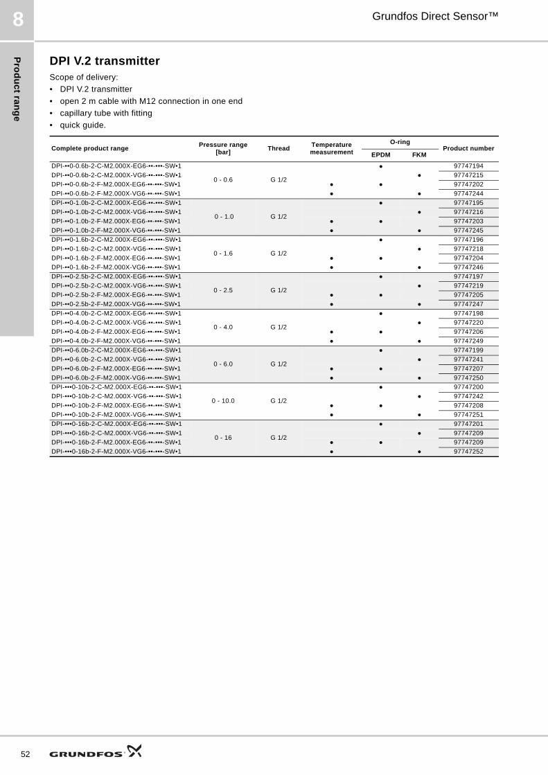
Pro
du
ct ra
ng
e
52
Grundfos Direct Sensor™8
DPI V.2 transmitterScope of delivery:
• DPI V.2 transmitter
• open 2 m cable with M12 connection in one end
• capillary tube with fitting
• quick guide.
Complete product rangePressure range
[bar]Thread
Temperature measurement
O-ringProduct number
EPDM FKM
DPI-••0-0.6b-2-C-M2.000X-EG6-••-•••-SW•1
0 - 0.6 G 1/2
● 97747194
DPI-••0-0.6b-2-C-M2.000X-VG6-••-•••-SW•1 ● 97747215
DPI-••0-0.6b-2-F-M2.000X-EG6-••-•••-SW•1 ● ● 97747202
DPI-••0-0.6b-2-F-M2.000X-VG6-••-•••-SW•1 ● ● 97747244
DPI-••0-1.0b-2-C-M2.000X-EG6-••-•••-SW•1
0 - 1.0 G 1/2
● 97747195
DPI-••0-1.0b-2-C-M2.000X-VG6-••-•••-SW•1 ● 97747216
DPI-••0-1.0b-2-F-M2.000X-EG6-••-•••-SW•1 ● ● 97747203
DPI-••0-1.0b-2-F-M2.000X-VG6-••-•••-SW•1 ● ● 97747245
DPI-••0-1.6b-2-C-M2.000X-EG6-••-•••-SW•1
0 - 1.6 G 1/2
● 97747196
DPI-••0-1.6b-2-C-M2.000X-VG6-••-•••-SW•1 ● 97747218
DPI-••0-1.6b-2-F-M2.000X-EG6-••-•••-SW•1 ● ● 97747204
DPI-••0-1.6b-2-F-M2.000X-VG6-••-•••-SW•1 ● ● 97747246
DPI-••0-2.5b-2-C-M2.000X-EG6-••-•••-SW•1
0 - 2.5 G 1/2
● 97747197
DPI-••0-2.5b-2-C-M2.000X-VG6-••-•••-SW•1 ● 97747219
DPI-••0-2.5b-2-F-M2.000X-EG6-••-•••-SW•1 ● ● 97747205
DPI-••0-2.5b-2-F-M2.000X-VG6-••-•••-SW•1 ● ● 97747247
DPI-••0-4.0b-2-C-M2.000X-EG6-••-•••-SW•1
0 - 4.0 G 1/2
● 97747198
DPI-••0-4.0b-2-C-M2.000X-VG6-••-•••-SW•1 ● 97747220
DPI-••0-4.0b-2-F-M2.000X-EG6-••-•••-SW•1 ● ● 97747206
DPI-••0-4.0b-2-F-M2.000X-VG6-••-•••-SW•1 ● ● 97747249
DPI-••0-6.0b-2-C-M2.000X-EG6-••-•••-SW•1
0 - 6.0 G 1/2
● 97747199
DPI-••0-6.0b-2-C-M2.000X-VG6-••-•••-SW•1 ● 97747241
DPI-••0-6.0b-2-F-M2.000X-EG6-••-•••-SW•1 ● ● 97747207
DPI-••0-6.0b-2-F-M2.000X-VG6-••-•••-SW•1 ● ● 97747250
DPI-•••0-10b-2-C-M2.000X-EG6-••-•••-SW•1
0 - 10.0 G 1/2
● 97747200
DPI-•••0-10b-2-C-M2.000X-VG6-••-•••-SW•1 ● 97747242
DPI-•••0-10b-2-F-M2.000X-EG6-••-•••-SW•1 ● ● 97747208
DPI-•••0-10b-2-F-M2.000X-VG6-••-•••-SW•1 ● ● 97747251
DPI-•••0-16b-2-C-M2.000X-EG6-••-•••-SW•1
0 - 16 G 1/2
● 97747201
DPI-•••0-16b-2-C-M2.000X-VG6-••-•••-SW•1 ● 97747209
DPI-•••0-16b-2-F-M2.000X-EG6-••-•••-SW•1 ● ● 97747209
DPI-•••0-16b-2-F-M2.000X-VG6-••-•••-SW•1 ● ● 97747252

Pro
du
ct
ran
ge
Grundfos Direct Sensor™ 8
DPI transmitterThe DPI transmitter is available as a single transmitter as well as in sets with capillary tubes.
Scope of delivery:
• DPI transmitter
• screws, nuts and washers for installation
• cable pin, 0.34 mm
• installation and operating instructions for Grundfos DPI transmitter.
See table below for special parts for each set.
Product descriptionPressure
range [bar]
Cable length[m]
Wall bracketMotor
bracketCapillary
tubeReducing pieceUNS 7/16"-R 1/4
Service instructions
Product number
DPI 0-0.6 Complete 0 - 0.6 1.5 ● 96561232
DPI 0-1.0 Complete 0 - 1.0 1.5 ● 96573681
DPI 0-1.6 Complete 0 - 1.6 1.5 ● 96573682
DPI 0-2.5 Complete 0 - 2.5 1.5 ● 96573683
DPI 0-4.0 Complete 0 - 4.0 1.5 ● 96573684
DPI 0-6.0 Complete 0 - 6.0 1.5 ● 96573685
DPI 0-10.0 Complete 0 - 10.0 1.5 ● 96573686
DPI 0-0.6 Set 1 0 - 0.6 1.5 ● ● ● ● ● 96611522
DPI 0-1.0 Set 1 0 - 1.0 1.5 ● ● ● ● ● 96611523
DPI 0-1.6 Set 1 0 - 1.6 1.5 ● ● ● ● ● 96611524
DPI 0-2.5 Set 1 0 - 2.5 1.5 ● ● ● ● ● 96611525
DPI 0-4.0 Set 1 0 - 4.0 1.5 ● ● ● ● ● 96611526
DPI 0-6.0 Set 1 0 - 6.0 1.5 ● ● ● ● ● 96611527
DPI 0-10.0 Set 1 0 - 10.0 1.5 ● ● ● ● ● 96611550
DPI 0-1.2 Set 2 0 - 1.2 5 ● ● ● 96760247
DPI 0-2.5 Set 2 0 - 2.5 5 ● ● ● 96760248
DPI 0-4.0 Set 2 0 - 4.0 5 ● ● ● 96760249
DPI 0-6.0 Set 2 0 - 6.0 5 ● ● ● 96760250
DPI 0-10.0 Set 2 0 - 10.0 5 ● ● ● 96829235
53

Ac
ce
ss
orie
s
54
Grundfos Direct Sensor™9
9. Accessories
Transmitter interface, SI 001 PSUThe SI 001 PSU from Grundfos Direct Sensors™ is an external power supply for the DPI and other transmitters with a supply voltage of 24 VDC.
The power supply must be used where the distance between the transmitter and the controller is longer than 30 m.
Fig. 167 Transmitter interface, SI 001 PSU
Specifications:
Voltage range: 110-400 VAC.
Frequency range: 50-60 Hz.
Ambient temperature: -20 to +50 °C.
Enclosure class: IP54.
M12 cable4-wire screened cable with M12 connector in transmitter end and open ends in equipment end.
Capillary tubeThe capillary tube is used together with the DPI / DPI+T to connect the transmitter to the low-pressure side of the equipment.
Adaptor for mounting in Grundfos CR pumpsThis adaptor is required when mounting the RPI / RPI+T or DPI / DPI+T in certain variants of CR pumps.
● Does not require an adaptor.❍ Requires an adaptor if the transmitter and coupling guard are in
direct contact (will create unnessesary acoustic noise). - Always requires an adaptor.
TM
04
41
94
08
09
Part Product number
Transmitter interface, SI 001 PSU 96915820
DescriptionLength
[m]Product number
Cable, industryM2.000X
2.00 96841343
Cable, industry M5.000X
5.00 96841344
Description Product number
Capillary tube UNS 7/16" 00ID5225
Pump typeGrundfos CR pump size
1 3 5 10 15 20 32 45 64 90 120 150
CR(E) ● ● ● ● ❍ ❍ ❍ - - - - -
CRI(E) ● ● ● ● ❍ ❍ - - - - - -
CRN(E) ● ● ● ● ❍ ❍ ❍ - - - - -
Description Product number
Extension adaptor for RPI / RPI+T and DPI / DPI+T
98255224

Ac
ce
ss
ori
es
Grundfos Direct Sensor™ 9
Transmitter interface, SI 010 CNVThe SI 010 CNV from Grundfos Direct Sensors™ is an external power supply, signal amplifier and signal converter for Grundfos transmitters.
The SI 010 CNV has built-in precision resistors enabling the transmitter to send 4-20 mA, 1-5 V and 2-10 V output signals.
The SI 010 CNV should be used in applications where transmitters from the standard product range are used, but the controller requires a 4-20 mA input signal.
Fig. 168 Transmitter interface, SI 010 CNV
Specifications:
Voltage range: 115-230 VAC ± 10 % or 24 VDC.
Frequency range: 50-60 Hz.
Power consumption: max. 2.5 W.
Ambient temperature: -20 to +50 °C.
Enclosure class: IP20.
TM
04
48
82
22
09
Part Product number
Transmitter interface, SI 010 CNV 96983684
55

Ap
pe
nd
ix
56
Grundfos Direct Sensor™10
10. Appendix
Temperature response of DPI V.2+T / RPI+T
!
>65 °C(>149 °F)
ISO 228/ 1 – G½
d1
d1 = 16.3 mm
d2 = 2.4 mm
d2
EPDM, FKM32 mm
20 Nm
M12
M12, IP67, UL CCN: CYJV and CYJV7
-25 to
60 °C60 C
(-13 to
140 °F)
Max.28 bar
(406 PSI)(406 PSI)IP67
-30 to 120 °C(-22 to 248 °F)
25 to

Fu
rth
er
pro
du
ct
do
cu
me
nta
tio
n
Grundfos Direct Sensor™ 11
11. Further product documentation
WebCAPS
WebCAPS is a Web-based Computer Aided Product Selection program available on www.grundfos.com.
WebCAPS contains detailed information on more than 220,000 grundfos products in more than 30 languages.
Information in WebCAPS is divided into six sections:
• Catalogue
• Literature
• Service
• Sizing
• Replacement
• CAD drawings.
Catalogue
Based on fields of application and pump types, this section contains the following:• technical data• curves (QH, Eta, P1, P2, etc.) which can be adapted to the
density and viscosity of the pumped liquid and show the number of pumps in operation
• product photos• dimensional drawings• wiring diagrams• quotation texts, etc.
Literature
This section contains all the latest documents of a given pump, such as• data booklets• installation and operating instructions• service documentation, such as Service kit catalogue and
Service kit instructions• quick guides• product brochures.
Service
This section contains an easy-to-use interactive service catalogue. Here you can find and identify service parts of both existing and discontinued grundfos pumps.Furthermore, the section contains service videos showing you how to replace service parts.
57

Fu
rthe
r pro
du
ct d
oc
um
en
tatio
n
58
Grundfos Direct Sensor™11
WinCAPS
Fig. 169 WinCAPS DVD
Sizing
This section is based on different fields of application and installation examples and gives easy step-by-step instructions in how to size a product:• Select the most suitable and efficient pump for your
installation.• Carry out advanced calculations based on energy,
consumption, payback periods, load profiles, life cycle costs, etc.
• Analyse your selected pump via the built-in life cycle cost tool.• Determine the flow velocity in wastewater applications, etc.
Replacement
In this section you find a guide to selecting and comparing replacement data of an installed pump in order to replace the pump with a more efficient grundfos pump. The section contains replacement data of a wide range of pumps produced by other manufacturers than grundfos.
Based on an easy step-by-step guide, you can compare grundfos pumps with the one you have installed on your site. When you have specified the installed pump, the guide will suggest a number of grundfos pumps which can improve both comfort and efficiency.
CAD drawings
In this section, it is possible to download 2-dimensional (2D) and 3-dimensional (3D) CAD drawings of most grundfos pumps.
These formats are available in WebCAPS:
2-dimensional drawings:• .dxf, wireframe drawings• .dwg, wireframe drawings.
3-dimensional drawings:• .dwg, wireframe drawings (without surfaces)• .stp, solid drawings (with surfaces)• .eprt, E-drawings.
WinCAPS is a Windows-based Computer Aided Product Selection program containing detailed information on more than 220,000 grundfos products in more than 30 languages.
The program contains the same features and functions as WebCAPS, but is an ideal solution if no internet connection is available.
WinCAPS is available on DVD and updated once a year.
0 1

Fu
rth
er
pro
du
ct
do
cu
me
nta
tio
n
Grundfos Direct Sensor™ 11
GO CAPS
Mobile solution for professionals on the GO!
CAPS functionality on the mobile workplace.
Subject to alterations.
59

GRUNDFOS A/S . DK-8850 Bjerringbro . DenmarkTelephone: +45 87 50 14 00www.grundfos.com
The name Grundfos, the Grundfos logo, and the payoff Be–Think–Innovate are registrated trademarks owned by Grundfos Management A/S or Grundfos A/S, Denmark. All rights reserved worldwide.
Being responsible is our foundationThinking ahead makes it possible
Innovation is the essence
97790251 0113
ECM: 1106677