Embed Size (px)
Citation preview

GRUNDFOS DATA BOOKLET
GRUNDFOS ALPHA2
Circulator pumps50 Hz

2
Contents
General dataCirculator pumps 3Type key 3Performance range 3Applications 4Pumped liquids 4Control of heating systems 5AUTOADAPT 5Operation 5Advantages of pump control 5Automatic Night SetBack 6Construction 7Sectional drawing 7Material specification 7Motor and control box 7Pump housing with air separator 8Installation 9Electrical data 9Start-up 9Liquid temperature 9System pressure 9Inlet pressure 9Setting of pump head 9Factory setting 9Change of performance 10Guide to performance curves 11Curve conditions 12
Technical data
AccessoriesUnion and valve kits 18Insulation kits 18Service kit 18
Further product documentationWebCAPS 19WinCAPS 20

GRUNDFOS ALPHA2General data
Circulator pumpsGRUNDFOS ALPHA2 is a complete range of circulator pumps featuring:
• AUTOADAPT function which suits most installations.• Integrated differential-pressure control enabling
adjustment of pump performance to the actual system requirements.
• Automatic Night SetBack (selectable).• Display showing the actual power consumption in
Watt.• Motor based on permanent-magnet/compact-rotor
technology.GRUNDFOS ALPHA2 is energy-optimised and A-labelled.
The energy label A indicates the energy-saving level of the pump. The energy classification system has seven levels, i.e. from A to G. Level A is the best.
The installation of a GRUNDFOS ALPHA2 pump will reduce the power consumption considerably, reduce noise from thermostatic valves and similar fittings, and improve the control of the system.
GRUNDFOS ALPHA2 offers a host of advantages:
Energy savings Automatic control of the differential pressure.
Flexibility Suitable for installation in existing systems.
Night setback Automatic Night SetBack (selectable).
Comfort Low-noise operation.
Safety Built-in electrical and thermal protection of the pump.
Userfriendliness Simple setting and operation.
Type key
Performance range
Fig. 1 Performance range, ALPHA2
Example ALPHA2 25 - 40 180Pump rangeNominal diameter (DN) of suction and discharge ports [mm] Maximum head [dm]
: Cast-iron pump housingN: Stainless-steel pump housingA: Pump housing with air separatorPort-to-port length [mm]
TM03
950
2 41
07
0.0 0.4 0.8 1.2 1.6 2.0 2.4 2.8 Q [m³/h]
0
1
2
3
4
5
6
H[m]
0
10
20
30
40
50
60
p[kPa]
0.0 0.2 0.4 0.6 0.8 Q [l/s]
GRUNDFOSALPHA2
ALPHA2 XX-40
ALPHA2 XX-60ALPHA2 XX-50
3

4
General data GRUNDFOS ALPHA2
ApplicationsGRUNDFOS ALPHA2 is designed for circulating liquids in heating systems. Pumps with stainless-steel pump housing can also be used in domestic hot-water systems.
GRUNDFOS ALPHA2 is suitable for
• systems with constant or variable flows where it is desirable to optimise the pump duty point.
• systems with variable flow-pipe temperature.• systems where night setback is desired.
GRUNDFOS ALPHA2 is especially suitable for
• installation in existing systems where the differential pressure of the pump is too high during periods of reduced flow demand.
• installation in new systems for fully automatic adjustment of the performance to flow demands without the use of bypass valves or similar expensive components.
Examples of systems
Fig. 2 One-pipe heating system
Fig. 3 Two-pipe heating system
Fig. 4 Underfloor heating system
Fig. 5 Domestic hot-water system
Pumped liquidsClean, thin, non-aggressive and non-explosive liquids, not containing solid particles, fibres or mineral oil.
The pump must not be used for the transfer of flammable liquids such as diesel oil, petrol and similar liquids.
TM03
899
0 45
07TM
03 8
989
4507
TM03
989
0 45
07TM
03 9
887
4507

General data GRUNDFOS ALPHA2
Control of heating systemsThe heating required in a building varies greatly during the day due to changing outdoor temperatures, solar radiation and heat emanating from human beings, electric appliances, etc.
Add to this that the need for heating may vary from one section of the building to another and that the thermostatic valves of some radiators may be turned down by the users.
These circumstances will cause an uncontrolled pump to produce a too high differential pressure when the heating demand is low.
Possible consequences:
• too high energy consumption• irregular control of the system• noise in thermostatic valves and similar fittings.GRUNDFOS ALPHA2 automatically controls the differential pressure by adjusting the pump performance to the actual heating demand, without the use of external components.
AUTOADAPT The integrated AUTOADAPT function is especially developed for
• underfloor heating systems• two-pipe systems. The AUTOADAPT function (factory setting) automatically adjusts the pump performance to the demand, i.e. the size of the system and the heating demand. The performance is adjusted gradually over time. An optimum pump setting cannot be expected from day one.
OperationThe AUTOADAPT function enables the ALPHA2 to control the pump performance automatically:
• Adjustment of the pump performance to the heating demand of the system.
• Adjustment of the pump performance to the variations in load over 24 hours.
In AUTOADAPT mode, the pump is set to proportional-pressure control.
Fig. 6 AUTOADAPT performance range
The AUTOADAPT function differs from other control functions as it moves the control curve within a performance range. The shaded area indicates the limits for the movement of the proportional-pressure curve. See fig. 6.
Advantages of pump controlIn GRUNDFOS ALPHA2, control is effected by adapting the differential pressure to the flow (proportional- and constant-pressure control).
Contrary to an uncontrolled pump, the proportional-pressure-controlled GRUNDFOS ALPHA2 reduces the differential pressure as a result of falling heating demand.
If the heating demand falls - for instance due to solar radiation - the radiator valves will close, and, for the uncontrolled pump, the flow resistance of the system will rise for instance from A1 to A2.
In a heating system with an uncontrolled pump, this situation will cause a pressure rise in the system by ΔH1.
Fig. 7 Uncontrolled pump
TM03
950
4 41
07TM
01 9
119
5002
H
Q
Max. curve
Proportional-pressure curve
Setpoint
H
Q
ΔH1
1
2
A2
A1
Q1Q2
5

6
General data GRUNDFOS ALPHA2
In a system with a GRUNDFOS ALPHA2 pump, the pressure will be reduced by ΔH2.
Fig. 8 Pump in proportional-pressure control mode
In a system with an uncontrolled pump, a pressure rise will often cause flow-generated noise in the thermostatic valves. This noise will be reduced considerably with the GRUNDFOS ALPHA2.
Automatic Night SetBackGRUNDFOS ALPHA2 features selectable Automatic Night SetBack.
Automatic Night SetBack is activated with the button on the control box.
Factory setting of Automatic Night SetBack: Not active.
Note: If the pump has been set to speed I, II or III, the night setback function is deactivated.
Once Automatic Night SetBack has been activated, the pump automatically changes between normal duty and night setback. Changeover is dependent on the flow-pipe temperature measured by the integrated temperature sensor.
TM01
912
0 50
02
H
Q
ΔH2
1A2
A1
A3
Q1Q2

General data GRUNDFOS ALPHA2
ConstructionGRUNDFOS ALPHA2 is of the canned-rotor type, i.e. pump and motor form an integral unit without shaft seal and with only two gaskets for sealing. The bearings are lubricated by the pumped liquid.
The pump is characterised by
• integrated AUTOADAPT control• integrated proportional-pressure control• integrated constant-pressure control• three fixed-speed curves• frequency converter• permanent-magnet/compact-stator motor• display showing the actual pump power
consumption in Watt (in whole numbers)• ceramic shaft and radial bearings • carbon thrust bearing • stainless-steel rotor can, bearing plate and rotor
cladding • composite impeller• cast-iron or stainless-steel pump housing• compact design featuring pump head with integrated
control box and control panel.
Sectional drawing
Fig. 9 Position numbers
Material specification
Motor and control boxThe motor is a 4-pole synchronous permanent-magnet motor.
The pump controller is incorporated in the control box, which is fitted to the stator housing with two screws and connected to the stator via a terminal plug.
The control box has an integrated control panel with two push-buttons (see pos. 1 and 2) and a 2-digit 7-segment display.
Fig. 10 Push-button positions
• Push-button (pos. 1) for selection of control mode.• Push-button (pos. 2) for activation or deactivation of
Automatic Night SetBack. The light in the display is on when the electricity supply has been switched on. During operation, the display shows the actual pump power consumption in Watt (in whole numbers). Accuracy: ± 5 %.
TM03
972
8 43
07
Pos. Description Material EN/DIN W.-Nr.
AISI/ASTM
1 Controller complete Composite, PC
9Rotor can Stainless steel 1.4301 304Radial bearing Ceramics
11Shaft CeramicsRotor cladding Stainless steel 1.4301 304
12Thrust bearing CarbonThrust bearing retainer EPDM rubber
13 Bearing plate Stainless steel 1.4301 304
16 Impeller Composite, PP or PES
18 Pump housing Cast iron Stainless steel
EN-JL 1020 EN 1.4308
A48-25 B
Gaskets EPDM rubber
TM03
849
9 17
07
7

8
General data GRUNDFOS ALPHA2
Faults preventing the pump from operating properly (e.g. blocking) are indicated in the display by "- -".
Possible control box positions:
Fig. 11 Control box positions
The cable entry incorporates cable relief.
Fig. 12 Cable entry with cable relief
Pump housing with air separator The pump housing with air separator is installed in systems where the liquid contains so much air that a circulator pump without air separator cannot start or keep up a continuous circulation. The pump housing is available only for upward water flows.
The air-containing liquid is guided from the suction port to the nozzle of the air-separating chamber and caused to circulate considerably in the relatively large chamber, thus creating a relatively lower pressure at the back (top) of the chamber. This lower pressure combined with the reduced velocity of the liquid in the air-separating chamber will cause a separation of air from the liquid. Due to its lower density, the air will escape through an automatic air vent fitted to the air-separating chamber.
The pump housing has an Rp 3/8 tapping for fitting of an air vent. The air vent is not supplied with the pump.
Fig. 13 Pump housing with air-separating chamber
Fig. 14 Air separation
TM03
849
7 17
07TM
01 9
184
1400
Standard position
TM03
849
8 17
07TM
00 9
101
1097
0 1 2 3 4 5 [%]
0
10
20
30
40
50
60
70
80
90
100
[%]Lu
ftuds
kille
lse
i %
Luftmængde i % af pumpemedie
Q=0,5 m³/h
Q=1,0 m³/h
Q=1,25 m³/h
Air
sepa
ratio
n as
%
Quantity of air as % of pumped liquid
Q = 0.5 m3/h
Q = 1.0 m3/h
Q = 1.25 m3/h

General data GRUNDFOS ALPHA2
Installation In most cases, the installation of the ALPHA2 is reduced to the mechanical installation and the connection to the electricity supply.
The pump must always be installed with horizontal motor shaft.
Fig. 15 Horizontal motor shaft
Electrical data
Start-upThe pump must not be started until the system has been filled with liquid and vented. Furthermore, the required minimum inlet pressure must be available at the pump inlet. The system cannot be vented through the pump.
The pump is self-venting. It need not be vented before start-up.
Liquid temperatureCast-iron pumps: +2 °C to +110 °C.
Stainless-steel pumps in domestic hot-water systems: +15 °C to +65 °C.
In domestic hot-water systems, it is recommended to keep the liquid temperature below 65 °C to eliminate the risk of lime precipitation.
To avoid condensation in the control box and stator, the liquid temperature must always be higher than the ambient temperature. See table.
System pressurePN 10: Maximum 1.0 MPa (10 bar).
Inlet pressureTo avoid cavitation noise and damage to the pump bearings, the following minimum pressures are required at the pump suction port.
Setting of pump headWith the push-button on the control box, the electronically controlled pump can be set to the following:
• AUTOADAPT operating area• two constant-pressure curves• two proportional-pressure curves• three fixed-speed curves.
Factory settingThe push-button on the pump control box is factory-set as shown in the table below.
This setting is suitable for a large majority of all single-family houses.
TM03
850
1 17
07
Supply voltage 1 x 230 V – 10 %/+ 6 %, 50 Hz, PE
Motor protection The pump requires no external motor protection.
Enclosure class IP 42Insulation class FRelative air humidity Maximum 95 %Ambient temperature 0 °C to +40 °CTemperature class TF110 to CEN 335-2-51EMC (electromagnetic compatibility) EN 61000-6-2 and EN 61000-6-3
Sound pressure level ≤ 43 dB(A)
Ambient temperature [°C]
Liquid temperature Min. [°C] Max. [°C]
0 2 11010 10 11020 20 11030 30 11035 35 9040 40 70
Liquid temperature 75 °C 90 °C 110 °C
0.5 m head 2.8 m head 10.8 m head
Pump type Setting Automatic Night Setback
ALPHA2 xx-40ALPHA2 xx-50ALPHA2 xx-60
AUTOADAPT Deactivated
9

10
General data GRUNDFOS ALPHA2
Change of performanceThe pump performance (flow and head) can be changed by pressing the control box push-button as indicated in the table below and fig. 16.
Fig. 16 Pump setting in relation to performance
TM03
920
8 36
07
IIIII
I
AUTOADAPT
AUTOADAPT
PP1PP2
CP1CP2
H
Q
Setting Pump curve Function
AUTOADAPT (factory setting)
Highest to lowest proportional-pressure curve
The AUTOADAPT function enables ALPHA2 to control the pump performance automatically within a defined performance range, see fig. 16:• Adjusting the pump performance to the size of the system.• Adjusting the pump performance to the variations in load over time.In AUTOADAPT, the pump is set to proportional-pressure control.
PP1 Lowest proportional-pressure curve
The duty point of the pump will move up or down on the lowest proportional-pressure curve, see fig. 16, depending on the heat demand.The head (pressure) is reduced at falling heat demand and increased at rising heat demand.
PP2 Highest proportional-pressure curve
The duty point of the pump will move up or down on the highest proportional-pressure curve, see fig. 16, depending on the heat demand.The head (pressure) is reduced at falling heat demand and increased at rising heat demand.
CP1 Lowest constant-pressure curve
The duty point of the pump will move out or in on the lowest constant-pressure curve, see fig. 16, depending on the heat demand in the system.The head (pressure) is kept constant, irrespective of the heat demand.
CP2 Highest constant-pressure curve
The duty point of the pump will move out or in on the highest constant-pressure curve, see fig. 16, depending on the heat demand in the system.The head (pressure) is kept constant, irrespective of the heat demand.
III Speed III
ALPHA2 runs at a constant speed and consequently on a constant curve.In speed III, the pump is set to run on the max. curve under all operating conditions. See fig. 16.Quick venting of the pump can be obtained by setting the pump to speed III for a short period. See 6.2 Installation and operating instructions.
II Speed II ALPHA2 runs at a constant speed and consequently on a constant curve.In speed II, the pump is set to run on the medium curve under all operating conditions. See fig. 16.
I Speed I ALPHA2 runs at a constant speed and consequently on a constant curve.In speed I, the pump is set to run on the min. curve under all operating conditions. See fig. 16.
ALPHA2 changes to the curve for Automatic Night SetBack, i.e. absolute minimum performance and power consumption, provided certain conditions are met. See Automatic Night SetBack.

General data GRUNDFOS ALPHA2
Guide to performance curvesEach pump setting has its own performance curve (Q/H curve). However, AUTOADAPT covers a performance range.
A power curve (P1 curve) belongs to each Q/H curve. The power curve shows the pump power consumption (P1) in Watt at a given Q/H curve.
The P1 value corresponds to the value that can be read from the pump display, see fig. 17.
Fig. 17 Performance curves in relation to pump setting
TM03
916
1 35
07
AUTOADAPT
AUTO
III
ADAPT
PP1PP2
CP1CP2
Q
P1
H
Q
III
II
I
Setting Pump curveAUTOADAPT(factory setting) Setpoint within the shaded area
PP1 Lowest proportional-pressure curvePP2 Highest proportional-pressure curveCP1 Lowest constant-pressure curveCP2 Highest constant-pressure curveIII Constant speed, speed IIIII Constant speed, speed III Constant speed, speed I
Curve for Automatic Night SetBack
11

12
General data GRUNDFOS ALPHA2
Curve conditionsThe guidelines below apply to the performance curves on the next pages:
• Test liquid: airless water.• The curves apply to a density of ρ = 983.2 kg/m3
and a liquid temperature of +60 °C.• All curves show average values and should not be
used as guarantee curves. If a specific minimum performance is required, individual measurements must be made.
• The curves for the speeds I, II and III are marked.• The curves apply to a kinematic viscosity of
υ = 0.474 mm2/s (0.474 cSt).• The conversion between head H [m] and pressure
p [kPa] has been made for water with a density of ρ = 1000 kg/m3. For liquids with other densities, e.g. hot water, the discharge pressure is proportional to the density.

Technical data
ALPHA2 15-40, 25-40, 32-40 1 x 230 V, 50 Hz
TM03
908
3 33
07 -
TM03
086
8 07
05
0.0 0.2 0.4 0.6 0.8 1.0 1.2 1.4 1.6 1.8 2.0 2.2 Q [m³/h]
0
1
2
3
4
[m]H
0
10
20
30
40
[kP a]p
0.0 0.1 0.2 0.3 0.4 0.5 0.6 Q [l/s]
IIIIII
0.0 0.2 0.4 0.6 0.8 1.0 1.2 1.4 1.6 1.8 2.0 2.2 Q [m³/h]
0
5
10
15
20
25[W ]P 1
III
II
I
Speed P1 [W] I1/1 [A]
Min. 5 0.05Max. 22 0.19
The pump incorporates overload protection.
Connections: See "Union and valve kits" on page 18.System pressure: Max. 1.0 MPa (10 bar).Liquid temperature: +2 °C to +110 °C (TF 110).
Also available with: Stainless-steel pump housing, type N (only ALPHA2 25-40 N 180).
TM03
921
5 36
07
Pump typeDimensions [mm] Weights [kg] Ship. vol.
[m3]L1 B1 B2 B3 B4 H1 H2 H3 G Net GrossALPHA2 15-40 130 77 78 46 49 27 129 79 1 1.9 2.1 0.00383ALPHA2 25-40 130 77 78 46 49 27 129 79 1 1/2 1.9 2.1 0.00383ALPHA2 25-40 (N) 180 78 77 47 48 26 127 81 1 1/2 2.1 2.3 0.00383ALPHA2 32-40 180 78 77 47 48 26 127 81 2 2.1 2.3 0.00383
GRUNDFOS ALPHA2
13

14
Technical data GRUNDFOS ALPHA2
ALPHA2 25-50 1 x 230 V, 50 Hz
TM03
908
4 33
07 -
TM03
086
8 07
05
0.0 0.2 0.4 0.6 0.8 1.0 1.2 1.4 1.6 1.8 2.0 2.2 2.4 2.6 Q [m³/h]
0
1
2
3
4
5
[m]H
0
10
20
30
40
50
[kP a]p
0.0 0.1 0.2 0.3 0.4 0.5 0.6 0.7 Q [l/s]
IIIIII
0.0 0.2 0.4 0.6 0.8 1.0 1.2 1.4 1.6 1.8 2.0 2.2 2.4 2.6 Q [m³/h]
0
5
10
15
20
25
30
35[W ]P 1
III
II
I
Speed P1 [W] I1/1 [A]
Min. 5 0.05Max. 32 0.27
The pump incorporates overload protection.
Connections: See "Union and valve kits" on page 18.System pressure: Max. 1.0 MPa (10 bar).Liquid temperature: +2 °C to +110 °C (TF 110).
TM03
921
5 36
07
Pump typeDimensions [mm] Weights [kg] Ship. vol.
[m3]L1 B1 B2 B3 B4 H1 H2 H3 G Net GrossALPHA2 25-50 130 77 78 46 49 27 129 79 1 1/2 1.9 2.1 0.00383ALPHA2 25-50 180 78 77 47 48 26 127 81 1 1/2 2.1 2.3 0.00383

Technical data GRUNDFOS ALPHA2
ALPHA2 15-60, 25-60, 32-60 1 x 230 V, 50 Hz
TM03
908
5 33
07 -
TM03
086
8 07
05
0.0 0.2 0.4 0.6 0.8 1.0 1.2 1.4 1.6 1.8 2.0 2.2 2.4 2.6 2.8 Q [m³/h]
0
1
2
3
4
5
6
[m]H
0
10
20
30
40
50
60[kP a]
p
0.0 0.1 0.2 0.3 0.4 0.5 0.6 0.7 0.8 Q [l/s]
IIIII
I
0.0 0.2 0.4 0.6 0.8 1.0 1.2 1.4 1.6 1.8 2.0 2.2 2.4 2.6 2.8 Q [m³/h]
0
10
20
30
40
50
[W ]P 1
III
II
I
Speed P1 [W] I1/1 [A]
Min. 5 0.05Max. 45 0.38
The pump incorporates overload protection.
Connections: See "Union and valve kits" on page 18.System pressure: Max. 10 bar.Liquid temperature: +2 °C to +110 °C (TF 110).
Also available with: Stainless-steel pump housing, type N(only ALPHA2 25-60 N 180).
TM03
921
5 36
07
Pump typeDimensions [mm] Weights [kg] Ship. vol.
[m3]L1 B1 B2 B3 B4 H1 H2 H3 G Net GrossALPHA2 15-60 130 77 78 46 49 27 129 79 1 1.9 2.1 0.00383ALPHA2 25-60 130 77 78 46 49 27 129 79 1 1/2 1.9 2.1 0.00383ALPHA2 25-60 (N) 180 78 77 47 48 26 127 81 1 1/2 2.1 2.3 0.00383ALPHA2 32-60 180 78 77 47 48 26 127 81 2 2.1 2.3 0.00383
15

16
Technical data GRUNDFOS ALPHA2
ALPHA2 25-40 A 1 x 230 V, 50 Hz
TM03
908
3 33
07 -
TM03
086
8 07
05
0.0 0.2 0.4 0.6 0.8 1.0 1.2 1.4 1.6 1.8 2.0 2.2 Q [m³/h]
0
1
2
3
4
[m]H
0
10
20
30
40
[kP a]p
0.0 0.1 0.2 0.3 0.4 0.5 0.6 Q [l/s]
IIIIII
0.0 0.2 0.4 0.6 0.8 1.0 1.2 1.4 1.6 1.8 2.0 2.2 Q [m³/h]
0
5
10
15
20
25[W ]P 1
III
II
I
Speed P1 [W] I1/1 [A]
Min. 5 0.05Max. 22 0.19
The pump incorporates overload protection.
Connections: See "Union and valve kits" on page 18.System pressure: Max. 1.0 MPa (10 bar).Liquid temperature: +2 °C to +110 °C (TF 110).
TM03
921
1 36
07
Pump typeDimensions [mm] Weights [kg] Ship. vol.
[m3]L1 B1 B2 B3 B4 H1 H2 H3 G Net GrossALPHA2 25-40 A 180 64 91 34 65 50 137 71 1 1/2 3.1 3.3 0.0063
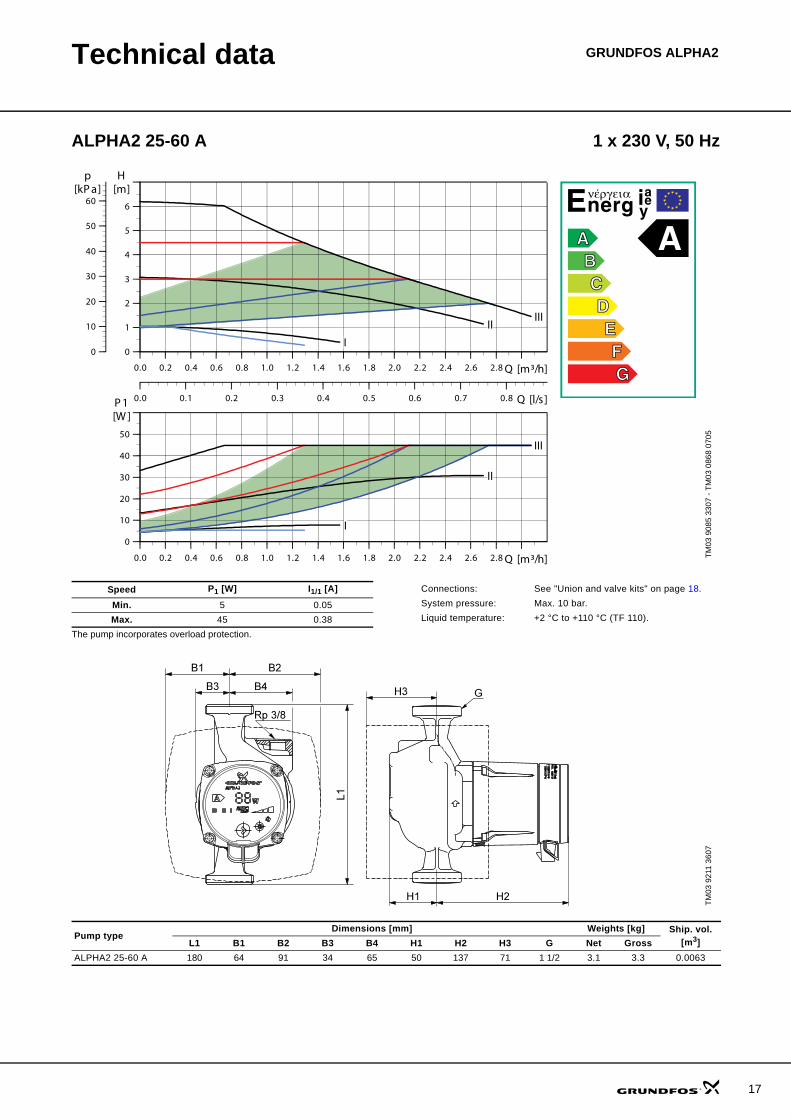
Technical data GRUNDFOS ALPHA2
ALPHA2 25-60 A 1 x 230 V, 50 Hz
TM03
908
5 33
07 -
TM03
086
8 07
05
0.0 0.2 0.4 0.6 0.8 1.0 1.2 1.4 1.6 1.8 2.0 2.2 2.4 2.6 2.8 Q [m³/h]
0
1
2
3
4
5
6
[m]H
0
10
20
30
40
50
60[kP a]
p
0.0 0.1 0.2 0.3 0.4 0.5 0.6 0.7 0.8 Q [l/s]
IIIII
I
0.0 0.2 0.4 0.6 0.8 1.0 1.2 1.4 1.6 1.8 2.0 2.2 2.4 2.6 2.8 Q [m³/h]
0
10
20
30
40
50
[W ]P 1
III
II
I
Speed P1 [W] I1/1 [A]
Min. 5 0.05Max. 45 0.38
The pump incorporates overload protection.
Connections: See "Union and valve kits" on page 18.System pressure: Max. 10 bar.Liquid temperature: +2 °C to +110 °C (TF 110).
TM03
921
1 36
07
Pump typeDimensions [mm] Weights [kg] Ship. vol.
[m3]L1 B1 B2 B3 B4 H1 H2 H3 G Net GrossALPHA2 25-60 A 180 64 91 34 65 50 137 71 1 1/2 3.1 3.3 0.0063
17