Embed Size (px)
Citation preview

������������Version 7
This manual written for Sabine GRAPHI-Qs with:• GRQ Firmware Version 3.10• GRQ Remote Software Version 3.10
Visit Sabine’s website for the latest information and FREEsoftware/firmware and operating guide updates
www.SabineUSA.com

�
Manufacturer's Name: Sabine, Inc.
Manufacturer's Address: 13301 Highway 441Alachua, FL 32615 USA
Type of Equipment: Equalizer
Model No.: GRAPHI-Q
Serial No.:
Year of Manufacture: 1999 and on
I, the undersigned, hereby declare that the equipment specified above conforms to the aboveDirective and Standard.
Place: Alachua, Florida, USA Signature:
Date: February 20, 2000 Full Name: Doran Oster, Sabine President
� ���������������������
DECLARATION OF CONFORMITY
Application of Council Directive: 73/23/EEC and 89/336/EEC
Standards to which conformity is declared:EN 60065: 1993EN 60742: 1995
EN 55103-1: 1997EN 55022: 08:94 + a1:05:05
EN 55103-2: 1997

�
GRQ-3101 (1U, single channel, one input, two outputs)
GRQ-3102 (2U, dual channel, one input & output per channel)
GRQ-3101S (1U, blank front panel slave, single channel, one input, two outputs)
GRQ-3102S (1U, blank front panel slave, dual channel, one input & output per channel)
GRQ Remote for WindowsTM Software included with every unit; runs up to 8 GRAPHI-Qs per COM port
(maximum of 2 COM ports)
• All front panel controls are analog-style; signal path is digital
• “Tweek-n-Peek” feature: Front panel adjustments of all parameters are shown in LED display screen
• 24-bit A/D and D/A conversion, 32-bit processing
• 20 to 20KHz Frequency Response
• +29 dBV Maximum Signal Input & Output
• ClipGuardTM Adaptive Clip Level Control
• Floating Point SHARC Processor
• >110 dB dynamic range (with ClipGuardTM)
Each channel provides:
• 31-band graphic EQ, with ± 6 or 12 dB range (selectable)
• High Cut Filter (3K to 20K) and Low Cut Filter (1K to 20K)
• FBX Feedback Exterminator: 12 Filters, with TURBO Mode (Auto Turbo mode via remote control)
• Compressor/Limiter, with controls for ratio, threshold, and gain (attack, release, and knee adjustable
with remote)
• Digital Delay, with up to 1 second delay, adjustable in 20 microsecond increments
• Bypass: dedicated switches for FBX, EQ, and Delay with built in LED indicators
• LED Segmented Indicators: FBX Filters, Level, Gain Reduction
• LED Point Indicators: TURBO, Remote, EQ Range
• LED Character Display: Delay setting, EQ fader boost/cut, High Cut Filter setting Low Cut Filter
setting, Compressor Ratio, Threshold, and Gain.
Back Panel:
• XLR & 1/4" TRS inputs & outputs
• RS-232 Serial input & output (additional serial input on the slave front panels)
• Remote switching (7-position contact closure switch; allows switch selection of all 69 stored GraphiQpresets)
GRAPHI-Q Remote Software Features:
All front panel controls, plus more, including:
• FBX filter depth & width adjustments; switchable to parametric filters (depth, width & frequency
adjustments)
• View and edit response curves
• Graphic EQ Filter width adjustments
• Password protection
• View & edit frequency response curves
• 69 user-defined stored presets• Control and link up to 8 GRAPHI-Qs (16 channels of audio) per COM port (1 or 2 ports can be used)• Future-proof FREE flash RAM upgrade capability: upgrade your firmware and software from the
Sabine website (www.SabineUSA.com)!
������� �� � ���� �
���������� ���� �

�
���� ������ ���
Table of Contents
Section One: Introduction .................................................................................................. 6
Section Two: Analog vs. Digital Signal Processing ........................................................... 7
Section Three: Front and Back Panel Views....................................................................... 8
Section Four: Block Diagram/Internal Signal Path ............................................................ 10
Section Five: Installation .................................................................................................... 115.1. BETWEEN MIXER OUTPUT AND POWER AMPLIFIER. .....................................................................11
5.2. TWO CHANNEL GRAPHI-Q: MAINS AND MONITORS. ......................................................................11
5.3. USE WITH A POWERED MIXER. .........................................................................................................12
5.4. USE AT A MIXER INSERT POINT. .......................................................................................................12
5.5. SINGLE CHANNEL GRAPHI-Q: ONE INPUT TWO OUTPUTS. ...........................................................12
5.6. WHAT NOT TO DO ...............................................................................................................................13
Section Six: Using GRAPHI-Q Front Panel Controls .......................................................... 146.1. GRAPHIC EQUALIZER CONTROLS ...................................................................................................14
6.1.1. Front Panel Control .................................................................................................................... 14
6.1.2. Linking Channel Controls (Two Channel Units) .......................................................................... 15
6.1.3. The Tweek-n-Peek Feature (Front Panel Models only) ............................................................... 15
6.2. HIGH CUT/LOW CUT FILTERS ...........................................................................................................15
6.2.1. Front Panel Control .................................................................................................................... 15
6.3. FEEDBACK CONTROL AND PARAMETRIC EQUALIZATION ............................................................15
6.3.1. Glossary of Terms ...................................................................................................................... 15
6.3.2. Front Panel Control of FBX filters ............................................................................................... 17
6.3.3. Adjustments Available Only with Remote Control ........................................................................ 19
6.4. COMPRESSOR/LIMITER CONTROLS ................................................................................................19
6.4.1. Front Panel Control .................................................................................................................... 19
6.5. DIGITAL DELAY CONTROLS ..............................................................................................................20
6.5.1. Front Panel Control .................................................................................................................... 20
6.6. BYPASS ..............................................................................................................................................20
6.6.1. Front Panel Control .................................................................................................................... 20
6.7. CHANGING FRONT PANEL DEFAULT SETTINGS ADJUSTABLE ONLY BY SOFTWARE.................20
Section Seven: GRQ-Remote Software Installation........................................................... 217.1. SYSTEM REQUIREMENTS AND RECOMMENDATIONS .....................................................................21
7.2. CONNECTIONS ...................................................................................................................................21
7.3. INSTALLING THE SOFTWARE.............................................................................................................22
Section Eight: Using GRQ-Remote Software ..................................................................... 238.1. WELCOME SCREEN/NETWORK CHAIN SCREEN ..............................................................................23
8.1.1. Default Control Status ................................................................................................................ 24
8.2. GRQ MAIN SCREEN ............................................................................................................................24
8.2.1. Graphic Equalizer ........................................................................................................................ 24
8.2.2. High/Low Cut Filters .................................................................................................................... 24

�
���� ������ ���
8.2.3. Response Curve Display ............................................................................................................ 25
8.2.4. Output Level ............................................................................................................................... 25
8.2.5. FBX Feedback Exterminator & Parametric Filters ....................................................................... 25
8.2.6. Compressor/Limiter Adjustments ................................................................................................ 28
8.2.7. Digital Delay Adjustments ........................................................................................................... 29
8.2.8. Bypass ........................................................................................................................................ 29
8.3. LINKING PARAMETERS AND CONTROL WITH THE GRQ-REMOTE SOFTWARE ............................30
8.3.1. How To Set Linked Groups ......................................................................................................... 31
8.3.2. Special Linking Considerations .................................................................................................. 31
8.4. RESET PARAMETERS ........................................................................................................................34
8.5. PRINTING GRAPHI-Q SETTINGS FOR DOCUMENTATION ................................................................34
8.6. STORING AND RECALLING GRQ PRESETS .....................................................................................35
8.6.1. Memory Storage and Recall Options .......................................................................................... 35
8.6.2. Contact Closure Switch Recall ................................................................................................... 36
8.7. ASSIGNING NAMES TO THE GRAPHI-QS ..........................................................................................37
8.8. PASSWORD PROTECTION WITH GRQ-REMOTE SOFTWARE ..........................................................37
8.8.1. Password Levels ....................................................................................................................... 37
8.8.2. Setting or Changing Passwords ................................................................................................. 38
8.8.3. Gaining Access With Your Password .......................................................................................... 38
8.8.4. Removing Password Protection.................................................................................................. 38
8.8.5. Passwords For Multiple Units ..................................................................................................... 38
8.9. NAVIGATING WITH MULTIPLE UNITS ................................................................................................39
8.10. UPGRADING GRAPHI-Q FIRMWARE AND SOFTWARE ...................................................................39
8.10.1 How to Upgrade Your Firmware.................................................................................................. 39
Section Nine: Suggestions for Optimal Use of the GRAPHI-Q .......................................... 419.1. SYSTEM SETUP SUGGESTIONS ......................................................................................................41
9.1.1. Acoustics. ................................................................................................................................... 41
9.1.2. Equipment Placement ................................................................................................................. 41
9.2. WIDE AND NARROW FILTERS: GRAPHIC, PARAMETRIC, AND FBX................................................42
9.3. RECOMMENDED EQ USAGE .............................................................................................................43
9.3.1. Set the Graphic EQ First ........................................................................................................... 43
9.3.2. Using FBX filters ......................................................................................................................... 44
9.3.3. Changing FBX filters to Parametric filters .................................................................................... 44
9.4. USING DIGITAL DELAY .......................................................................................................................45
9.4.1. Loudspeaker Synchronization ..................................................................................................... 45
9.4.2. Comb Filter Distortion ................................................................................................................ 46
9.4.3. The Precedence Effect: Aligning the Acoustic Image ................................................................ 48
9.4.4. Three Applications for Digital Delays .......................................................................................... 48
9.5. USING THE COMPRESSOR/LIMITER ..................................................................................................51
9.5.1. Suggested Compressor Settings ................................................................................................. 52
Section Ten: Troubleshooting Tips ..................................................................................... 53
Section Eleven: GRAPHI-Q Engineering Specifications ................................................... 55
Section Twelve: Cautions & Warranty ................................................................................. 56

�
Congratulations on your purchase of the Sabine GRAPHI-Q. This product represents our latestbreakthrough in our never-ending quest to improve the world’s sound.
Aside from the powerful array of features packed into a single unit (graphic EQ, FBX filters, parametricfilters, high and low cut filters, delay, compression, and limiting), the GRAPHI-Q also offers a choice ofuser interfaces.
Computer control: learn to love it. As the world becomes an increasingly digital place, the computeris omnipresent. Some regard this as a mixed blessing. In audio applications, the downside of computer-controlled digital audio stems from the unfamiliarity and operational limitations of its control interface.After years of experience with analog controls, many sound engineers prefer the “hands-on” approachto control audio with knobs and faders. It’s intuitive and direct. To the analog lover, typing commandson a keyboard feels awkward and may require redirecting one’s attention to the control interface, ratherthan the sound emerging from the speakers.
On the other hand, there is no question that the digital signal processing available through a computerinterface offers improved precision and reliability of control over your audio. Equalization adjustmentsin the digital realm are exceptionally accurate, offer pinpoint resolution, and minimize phase distortionand frequency drift. Compressor parameters not only can be set quite precisely, but also offer anexpanded range of adjustment and ease of storage and recall that are much more difficult to achievewith analog technology. And, with the Sabine FBX algorithm, one of the most serious problems of audioamplification — that lovely howling sound we call feedback — can be removed with the precision anddelicacy of laser surgery.
Analog AND Digital - Best of Both Worlds. The GRAPHI-Q combines the best of both worlds. If youneed to put your hands on faders and knobs to fully experience audio, we offer you the ease and comfortof our “analog-style” front panel. Push, pull, turn, and tweak to your heart’s content!
If your fingers naturally gravitate toward computer keyboards, the GRAPHI-Q offers your kind of userinterface as well. Each GRAPHI-Q comes equipped with an RS-232 serial interface and the SabineGRAPHI-Q Remote for WindowsTM software. All the front panel controls, and some important additionalones, can be adjusted from your computer keyboard. And if you’re seriously addicted to the thrill ofpunching keys, you can save some money as you indulge yourself with a GRAPHI-Q Blank Front PanelSlave unit. Only controllable via computer, these models make mis-adjustment by unauthorized,untrained, or unthinking individuals impossible!
Whatever your control preference, the GRAPHI-Q opens up a world of signal processing powerpreviously unavailable at its exceptional price. All specifications are top notch (24-bit A/D and D/A, 32-bit internal processing) and all of its functions operate concurrently and ergonomically. So allow us tosuggest you read and study this entire manual to understand the whole story. Enjoy!
� ������� ������ ������
� ������� ������ ������

�
� ������!�������"#�$��"������"������� ����"
� ������!�������"#�$��"������"������� ����"
The ongoing debate continues: what sounds better, digital or analog signal processing? Audio engineersALL have an opinion on this, but the lack of documented research on the topic makes all conclusionstentative. Nonetheless, the audio industry is slowly moving to digital as circuit designs continuouslyimprove and technology advances into the realm of 24-bit resolution — which provides finer audio detail,particularly at low levels of dynamic range. The tentative conclusion we would suggest is that the soundof digital circuits is widely variable, encompassing the capacity to sound remarkably like analogcircuits…and much more. Beyond these considerations, however, there are undeniable advantages todigital signal processing…and one disadvantage that we believe we have solved with the SabineGRAPHI-Q.
THE ADVANTAGES:
1. GREATER PRECISION AND REPEATABLE ACCURACY. Analog circuitry produces less exactand repeatable adjustment. Identical analog circuits may produce different results when processingan identical audio signal, due to the tolerance of components comprising the analog circuit. Digitalcircuits rely on repeatable mathematical calculations and thus are more consistent. For equalizers,this means that the slope, shape, and symmetry of digital EQs are consistent across frequencies,and from one application to the next.
2. LESS PHASE DISTORTION. All equalizers cause some degree of phase shifting. In analog filters,this phase shift exceeds the width of the filter—often by a considerable margin. In other words, thephase shift encompasses frequencies beyond the boost or cut range of the filter. With digital filters,this phase shift can be restricted to within the filter width.
3. LESS FILTER DRIFT. Analog circuits rely on components that vary as they age and/or aresubjected to different ambient temperatures. This variation can in turn cause analog filters to driftfrom their original settings. In contrast, digital filters are based on mathematical formulas and willremain constant over time and changing temperatures.
4. LESS NOISE. As analog parts wear, get dirty, or corrode, readjusting them can introduce noise intothe signal path. All audio engineers are familiar with the sound of a “scratchy fader.” Digital controlsaffect the signal, but are not actually in the audio path and thus cannot introduce noise.
5. RECALL AND STORAGE OF SETTINGS. Because digital filters can be represented mathemati-cally, settings are easily stored, recalled, and copied to other channels or units. Analog filters aredependent on the physical position of potentiometers and sliders, and storing and recalling settingsrequires servo motors and automated repositioning of controls. This is both more expensive to buildand produces less accurate results.
6. COST. As technology improves, features increase and prices plummet. Nowhere is this trend moreapparent than in the digital world. DSP circuitry is generally smaller, less costly, and more powerfulthan comparable analog circuitry, which means you get a lot more bang for your buck (orDeutschMark, pound, or peso) with a digital box. Compare the price of the GRAPHI-Q to a highquality analog graphic equalizer, and you’ll see what we mean—especially when you add acompressor, delay, FBX and parametric EQ, and software interface to the comparison.
THE DISADVANTAGES.
1. FAMILIARITY AND EASE OF USE. The sole disadvantage of digital processors that few if anysound engineers will argue has to do with the familiarity and user-friendliness of the digital controlinterface. Many powerful DSP products are menu-driven and difficult to use. One very specialfeature of the GraphiQ 3102 and 3101 models is the familiar analog-style interface of the front panel.The control surface looks, feels, and operates like a graphic equalizer from the 1970’s—with thepower and features of 21st century technology. If you’re a 21st century technophile who lovescomputers and knobs, then you won’t be disappointed either—just plug in a serial cable, load up thesoftware, and you’ll find a whole new world of hacker-pleasing software control waiting for yourcommand.
The GRAPHI-Q truly offers the best of both worlds — or maybe even the best of three worlds and fivedimensions.

�
� ������%� �������� &��'��� �(� !�
� ������%� �������� &��'��� �(� !�
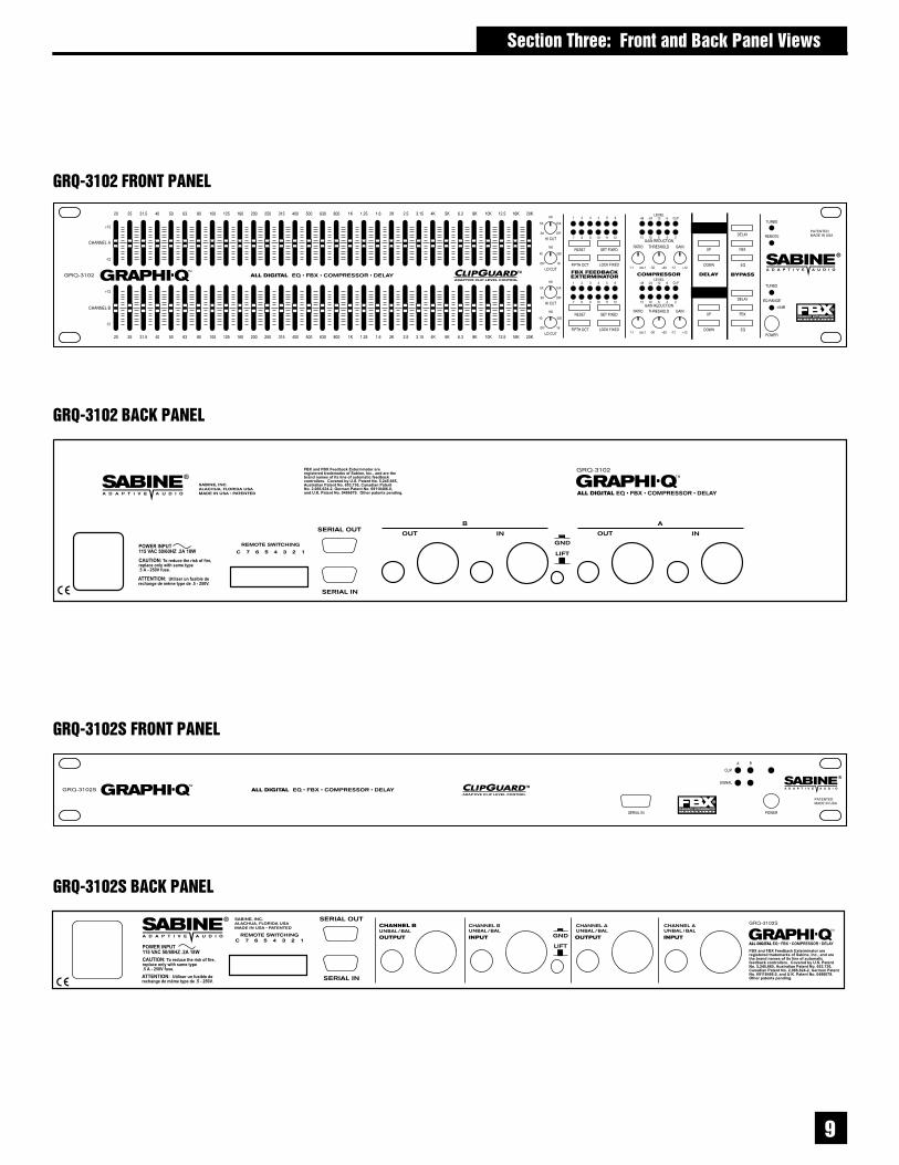
Clip LED-lightsat 3 dB belowclipping SignalLED-lights wheninput is above30 dBV peak
�)*+,-,&��.����/
Phoenix block connectorsFor contact closure switch
RS-232 Serial InConnect to serial portof PC, or previousGRQ in chain
RS-232 Serial OutConnect to nextGRQ in chain 1/4” TRS connectors
Ground Lift SwitchDiffering ground potentials between oramong interconnected equipment mayintroduce hum or noise in audio. Thisground lift isolates pin 1 or input XLR fromsignal ground (chassis ground isolated)
Power connector& fuse
�)*+,-,����������/
AdditionalRS-232 Serial In Power On LED
�)*+,-,�&��.����/
�)*+,-,���������/
FBX Section12 filter indicatorsReset, Width,Set, & Lock Fixed FilterControls
Compressor SectionLevel IndicatorsRatio, Threshold, & Gain controls
Bypass Controls
Status LEDsTURBO - Fast FBX SetupREMOTE - GRQ Remote activeEQ Range - EQ fader range indicator
EQ fadersAdjust boost/cut for 31specific frequencies
High & Low Cut Filters
Input signal &gain reductionindicators
Digital Delayup & down controls.EQ rangePress up & down buttons simulta-neously to toggle EQ range between+6 dB and +12 dB
Digital Delay / Tweek-n-Peek DisplayDigital delay time value displayed. Also momentarily displayscurrent firmware at power up, or value of any front panelcontrol altered.
XLRXLRXLR
�
� ������%� �������� &��'��� �(� !�
�)*+,-0���������/
�)*+,-0&��.����/
�)*+,-0�&��.����/
�)*+,-0����������/

� ����������&���'���"���1��� ������"������%
� ����������&���'���"���1��� ������"������%

The GRAPHI-Q should be placed in a well-ventilated, well-grounded equipment rack, preferably withineasy reach of the sound engineer. GRAPHI-Q slave units need not be as immediately accessible, sincecontrol is through a computer interface.
2$,$&��3���4�5�������������3���4�/�����$The most common placement of the GRAPHI-Q in a sound system is between the output of a mixingconsole and the input to a power amplifier. If your system requires a crossover or additional delays (suchas the Sabine DQX-206), put the GRAPHI-Q in line after the mixer, but before those units. Thisconfiguration will look like this:
This configuration represents the simplest installation, using a single channel (one input,using only one output) GRAPHI-Q. You may also follow a similar connection diagram for a two-channelGRAPHI-Q. Simply patch your left and right main outputs from your mixing console into the left and rightinputs of your GRAPHI-Q, then into two single channel power amplifiers, or bothchannels of a stereo amp.
2$0$�3��6����/���6�*)�4�������4�������$Alternatively, with a two-channel GRAPHI-Q, you may elect to route one mixer output through GRAPHI-Q channel A into a power amp driving your main speakers, and your mixer monitor output into GRAPHI-Q channel B, routed to your monitor speakers. This configuration is diagrammed below:
� �������# �������������
� �������# �������������
�
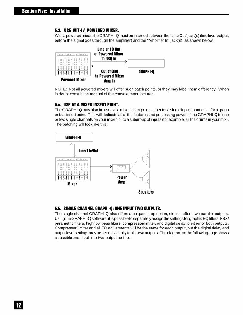
2$+$���3��6���3����4�5��$With a powered mixer, the GRAPHI-Q must be inserted between the “Line Out” jack(s) (line level output,before the signal goes through the amplifier) and the “Amplifier In” jack(s), as shown below:
NOTE: Not all powered mixers will offer such patch points, or they may label them differently. Whenin doubt consult the manual of the console manufacturer.
2$7$������4�5�������������$The GRAPHI-Q may also be used at a mixer insert point, either for a single input channel, or for a groupor bus insert point. This will dedicate all of the features and processing power of the GRAPHI-Q to oneor two single channels on your mixer, or to a subgroup of inputs (for example, all the drums in your mix).The patching will look like this:
2$2$���/��6����/���6�*)����������3��������$The single channel GRAPHI-Q also offers a unique setup option, since it offers two parallel outputs.Using the GRAPHI-Q software, it is possible to separately assign the settings for graphic EQ filters, FBX/parametric filters, high/low pass filters, compressor/limiter, and digital delay to either or both outputs.Compressor/limiter and all EQ adjustments will be the same for each output, but the digital delay andoutput level settings may be set individually for the two outputs. The diagram on the following page showsa possible one-input-into-two-outputs setup.
� �������# �������������

�
2$8$36���������
The GRAPHI-Q should NOT be used in the following configurations:
1. Do NOT plug a microphone directly into the GRAPHI-Q back panel. The GRAPHI-Q is designedfor operation with line level signals only. Your microphone signal must first go through a wirelessreceiver, mixer, preamp, etc. that will boost its output gain to line level.
2. Do NOT use the GRAPHI-Q in an auxiliary or effects loop, such as would be used to add reverbto different channels in your mixer. Effects loops are designed to split signal paths, and then mix“wet” processed signals with the “dry” signal path. The GRAPHI-Q is designed for use as an “in line”processor, meaning all the signal path should be routed through it.
3. Do NOT mix balanced and unbalanced inputs and outputs to and from the GRAPHI-Q. This willresult in a reduction of signal level.
� �������# �������������
FBX, parametric EQ, compressionand graphic EQ can be applied toeither or both outputs.

�
� �������9�����"���6�*)�������� ���������
� �������9�����"���6�*)��������
Many GRAPHI-Q owners will be immediately familiar with the simple operation of the front panel controls.Operation of these controls will be very similar when using an RS-232 connection to control GRAPHI-Q functions from a Windows-based computer platform (see Section Eight).
8$,$���6���)��/�:��������/�Please make note of the default front panel control protocols that apply when setting graphic EQ, FBXfilters, compression, delay, and output level for the two outputs of the single-input GRAPHI-Q (GRQ-3101). All processing, INCLUDING delay, is applied to Output B in the factory default setting. Allprocessing EXCEPT delay is applied to Output A. Therefore, all graphic EQ, FBX, and compressionadjustments will apply to both outputs, while front panel delay adjustments will affect only the B output.Remote control operation of the GRQ-3101 will enable separate delay and output level control settingsfor Outputs A and B. All other processing (graphic EQ, parametric EQ, and compressor/limiter settings)can be applied to one or both outputs using software control, but the GRQ-3101 will not permit uniqueoutput settings for any processing except delay, and for the output levels.
8$,$,$�������� ��������The GRAPHI-Q graphic EQ sliders have a center detent, calibrated to zero boost/cut at the factory.Raising the slider above the detent boosts a frequency band surrounding the center point nominalfrequency; lowering the slider below the detent cuts the frequency band. The GRAPHI-Q comesfrom the factory set to a ±12 dB boost/cut range. You may change this to a ± 6 dB range (and backagain) by pressing and holding the delay up/down buttons simultaneously for approximately onesecond. An LED in the lower right section of the front panel will indicate the 6 dB range conditionwhen it is illuminated. For two channel GRAPHI-Q units, pressing and holding either channel’sdelay up/down buttons will switch both channels’ EQ ranges simultaneously. It is not possible toselect different ranges for the two channels.
NOTE: Pulling down the A channel sliders causes the B channel to become the master for bothchannels. This also slaves the compressor, high & low cut filters, and output gain. Delay, bypass,and FBX controls remain channel specific.

�
� �������9�����"���6�*)��������
8$,$0$ /��'��" �%��� � �������� ;�!� �%��� � �����<Two channel GRAPHI-Q units offer a useful and unique feature for linking channel controls. Pulling allthe A channel EQ sliders to the bottom defeats these controls, and applies the B channel settings to theA channel as well. Now the B channel sliders act as master control for both channels. This applies notonly to the graphic EQ controls, but to controls for the compressor, high and low cut filters, and outputgain. Delay, bypass, and FBX filter controls will remain channel specific (in other words, to bypass thegraphic EQ for the A, you must press “Bypass” for channel A).
8$,$+$ �% �! '*�*� ' � ���� ;����� ��� � 4� �� ����<If you’ve been experimenting with the controls on your GRAPHI-Q front panel, you’ve probably already figured out Sabine’s new“Tweek-n-Peek” feature. If you’ve ever grabbed a graphic EQfader, moved it, and wondered what the “real” setting was, yourprayers have been answered. Tweek-n-Peek shows you the valueof every control on the front panel while you adjust them. As youmove a compressor knob or EQ slider, the value of the setting forthat control will appear in the LED screen that normally displays thedigital delay time. After two seconds of no further adjustment, thedisplay will revert to the digital delay setting. This means you canadjust all your controls to a precise, repeatable setting, not just toa vague knob or fader position. The accuracy of your settings forall the parameters of your GRAPHI-Q is thus significantly im-proved. The resolution of front panel graphic EQ fader settings is½ dB when the range of boost/cut is +6 dB, or 1 dB when the rangeof boost/cut is +12 dB. (When using the remote software to controlthe EQ faders the resolution is always ½ dB, regardless of range.)
8$0$6�6���1/�3�����/����
8$0$,$ ����� ��� � �������These controls are located immediately to the right of the graphic EQ sliders. For the LOWCUT FILTER, the GRAPHI-Q will attenuate frequencies at and below your knob setting witha slope of 12 dB per octave. For the HIGH CUT FILTER, frequencies at and above the knobsetting will be attenuated 12 dB per octave. The extreme counterclockwise knob position ofthe LOW CUT FILTER and the extreme clockwise position of the HIGH CUT FILTER turn thefilters off. The range of the HIGH CUT FILTER extends from a starting point of 3 KHz to 20KHz. The range of the LOW CUT FILTER extends from 20 Hz at the bottom to 1 KHz at thetop. The frequency chosen is the point at which attenuation of the filter reaches 3 dB. In otherwords, the filter roll-off actually begins just above (for low cut filter) or below (for high cut) thechosen frequency.
8$+$����&��.������/�������4������)��/�:�����Operation of the FBX Feedback Exterminator section of the front panel of your GRAPHI-Q is simple, butmay require a brief explanation for those of you unfamiliar with Sabine FBX products and/or terminology.Let’s begin by defining a few key terms.
8$+$,$ ������� �� � ���
• FEEDBACK describes what happens when a loudspeaker disperses sound back into an amplifiedmicrophone, and at a level sufficient to allow one or more frequencies to ring out of control. Feedbackcan occur at any frequency, but is especially painful at mid to high frequencies. The specificfrequencies that feedback in a particular situation depend on the acoustics of the environment, theplacement of the microphone(s) and speaker(s), the response characteristics of the sound systemcomponents, and the volume of amplification. Anyone who has operated a sound system or attendeda conference or a concert is familiar with feedback and its unpleasant consequences!

�
• A PARAMETRIC EQUALIZER allows the user to precisely specify three critical values thatdetermine an equalizer’s quality: the center frequency of the EQ band that is boosted or cut(measured in Hertz), the amount of boost or cut imposed at the center point (measured in dB), andthe width of the bell-curve shaped frequency band that is affected (typically measured in octaves).
• An FBX FILTER is essentially an automatically placed, narrowly attenuated parametric filter, withthe center point of its narrow cut tuned to a precise frequency that feeds back when a sound systemamplifies one or more microphones to a sufficient volume. The GRAPHI-Q will automatically placeup to 12 FBX filters in the signal path, corresponding to 12 distinct frequencies of feedback.
• A FIXED FBX FILTER will not change the frequency of the filter notch. Once it sets itself, it remainsat the same frequency. However, unless it is LOCKED, a FIXED FILTER may move its notch deeperwithout changing frequency. Fixed filters are typically set by turning up system gain to the point offeedback prior to sound check or performance, and will represent the “first layer” of feedbackprotection.
• A DYNAMIC FBX FILTER acts like a Fixed filter, until all available FBX filters (Fixed or Dynamic)are in use and a new frequency begins to feedback. When this happens, whichever Dynamic filterwas set earliest in the performance will drop its original frequency and move to the new one. Dynamicfilters are especially useful with mobile or wireless microphones (where feedback frequencies maychange due to microphone repositioning) and represent the “second layer” of feedback protection.Note that both Fixed and Dynamic filters can be set while music is playing, as one of thedistinguishing properties of the Sabine FBX algorithm is its ability to distinguish music (or speech,or other sounds) from feedback.
• A LOCKED FBX FILTER is a Fixed filter locked in place; i.e., it cannot get any deeper or changeits frequency. Locking filters prevents the placement of unnecessary filters in the signal path.
• FILTER WIDTH generally refers to the width (measured in octaves, or fractions thereof)of an equalizer, including graphic EQ filters, parametric filters, and FBX filters. More specifically,width is defined by determining the outer frequencies (surrounding the filter center point) that arealtered ± 3 dB when the filter is imposed. This is shown in the diagram below:
In this example, the filter widthis defined as approximatelyone-half octave, correspond-ing to the band of frequenciesattenuated 3 dB or more whenthe filter is pulled down. In thisexample, the width is the samewhether the filter depth is -9 dBor -19 dB.
• CONSTANT Q filters arefilters whose widths remainconstant regardless of theamount of boost or attenu-ation imposed by the fil-ters. In other words, in theabove example, a ConstantQ filter would remain a half-octave wide regardless ofthe EQ slider position.Some EQ units on the market are Constant Q; others are Proportional Q, meaning the filter gets wideras it gets deeper. All Sabine products use Constant Q filters, to prevent affecting any more soundthan necessary.
� �������9�����"���6�*)��������
True Constant Q filters:widths remain constantas the filters get deeper.Standard on all Sabineproducts.

�
• TURBO MODE refers to Sabine’s unique, exceptionally fast method of placing FBX filters duringsound system setup. TURBO MODE is less “fussy” about analyzing the sound it hears and is morelikely to regard audio signals over a minimum threshold as feedback. It’s also designed to allow feedbackto occur at lower input levels, and, finally, it imposes a strong limiter on the feedback output as it occurs.The net result of all this black magic is that you are able to ring out feedback more quickly, and at a muchquieter level! You’ll know TURBO MODE is engaged when the Turbo LED (at the right of the front panel)is illuminated.
4�.��������&�4��������36��=������6����6�*)��=������������/)��/��=4�=������>
(See Section 6.3.2.3 Turbo Mode Cautions).
8$+$0$ ����� ��� � ������� �� �&5 ���� ��Note: Most of the front panel and GRQ-Remote control operation of the FBX section of the GRAPHI-Q is similar, except that the remote control replaces your fingers with a mouse. In addition, there aresome controls offered only with GRQ-Remote software. These features are summarized in SectionEight.
Controls for the patented FBX Feedback Exterminator are located immediately to the right of the HIGHand LOW CUT FILTERS.
6.3.2.1. FBX Filter LED Indicators. The 12 LEDs on the front panelGRAPHI-Q correspond to 12 available FBX filters. Each time an FBX filtersets, another LED will light. A blinking LED indicates which filter was mostrecently set or made deeper (a filter may start at one depth and notch deeperat the same frequency as the system gain increases). The GRAPHI-Qcomes preset from the factory to a default setting of nine Fixed and threeDynamic filters. However, you may follow the instructions in STEP 5 belowto reconfigure the setup to be any combination of Fixed and Dynamic filters.
6.3.2.2. Eliminating Feedback with the GRAPHI-Q FBX Filters. Followthese steps to obtain the maximum gain before feedback, with minimal or noloss in the tonal quality of your program. The steps that follow are applicableto setting up a one-channel unit (GRQ-3101). When using the GRQ-3102, werecommend setting up one channel at a time by turning down the otherchannel of the power amplifier. If you are using both outputs of your GRQ-3101, you may wish to turn down the power amp gain for whichever outputis less likely to produce feedback. If both channels are equally feedbackprone, leave the power amps turned up. This will allow you to set filters thatare specific to each channel of your sound system.
STEP ONE: EQUIPMENT SETUP.Set up your sound system and position all the speakers and microphones you anticipate using. Whenpossible, avoid placing microphones directly in front of speakers.
STEP TWO: TURN OFF NOISE GATES.If there is any equipment in the signal path that incorporates a noise gate function, you MUSTDISENGAGE these noise gates prior to the setup procedure. You may reengage them upon setupconclusion.
STEP THREE: GAIN DOWN, TURN ON.Set the master volumes on your mixer to their lowest gain positions. Turn on the mixer, then the GRAPHI-Q, then any other accessories, and finally your power amplifier. Adjust the gain settings and balancefor all your microphones, but keep your master mixer volume down.
STEP FOUR: RESET FILTERS.If there are FBX filters already set (indicated by illuminated LEDs), you should RESET these filters.(NOTE: For maximum FBX power, we recommend resetting filters every time you change or move yoursound system.)
� �������9�����"���6�*)��������
�
The GRAPHI-Q allows two stages of filter resetting. You may reset only the Dynamic filters, or you mayelect to reset all (both Fixed and Dynamic).
- To RESET DYNAMIC FILTERS ONLY, press and hold the RESET button long enough for theDynamic filter LEDs to flash three times, then release.
- To RESET ALL FILTERS, press and hold the RESET button for seven flashes of all the LEDs, thenrelease.
Note that resetting all filters automatically engages TURBO MODE, which will allow feedback to occurand be removed more readily, and at a lower volume. “TURBO MODE on” will be indicated by the TURBOLED (at the right of the front panel) illuminating.
STEP FIVE: SET FIXED FILTERS (Optional)If you want to change the factory default setting of nine Fixed and three Dynamic FBX filters, press andhold the SET FIXED button for approximately four seconds. The corresponding LEDs for all filters setto FIXED will blink four times and turn off. Release the SET FIXED buttons, and the LEDs will begin tolight in sequence. When the LED corresponding to the desired number of fixed filters lights, press theSET FIXED button again. You’ve successfully set the number of fixed filters. All remaining filters willautomatically default to Dynamic filters—Unless you are setting filters with your computer.(See Section Eight)
STEP SIX: SET FBX FILTER WIDTH (Optional)FBX filters default to a Constant Q width of one-tenth of an octave. Extensive Sabine research has shownthis width to be an ideal setting, wide enough to remove feedback with very little or no effect upon therest of the audio program. In some applications (for example, speech-only applications, where audioquality is not as demanding as in a music program), however, it may be possible to use a wider filter formore robust feedback elimination.
The GRAPHI-Q allows you to mix filter widths between one-tenth and one-fifth octaves. You may setall filters to one width, or some filters to tenth-octave and some to fifth-octave. Width selection iscontrolled by the button marked “FIFTH OCT” directly below the RESET button. When this button ispushed and the LED is illuminated, any filters set after that point will be one-fifth octave wide. Pushingthe button again, and switching off the LED, will make any additional filters one-tenth octave wide.
STEP SEVEN: RAISE MASTER GAIN.First, make sure your GRAPHI-Q is not set to bypass the FBX filters (check the Bypass button LED;it should be off). Then, make sure your power amplifier is turned up and your microphones are turnedon. (Note: If you reset the FBX filters, your GRAPHI-Q will be in TURBO MODE, as indicated bythe front panel TURBO LED. See the cautions below.) Slowly raise the master gain of your mixeruntil the first feedback begins. The FBX will quickly remove the feedback, by setting the first filter andlighting the first filter LED. Continue to raise the gain slowly. Try to avoid making two or more frequenciesfeed back at the same time, which sometimes happens if the gain is too high. As new frequencies feedback, new filters will be placed, as indicated by consecutive filter LEDs lighting up. (Note: sometimesthe same frequency will feed back a second time, and an earlier filter will notch more deeply. When thishappens, the original LED indicating this frequency will blink, showing it to be the most recently activefilter.) Repeat this procedure until one of two things happens:
1. All of the Fixed filters and at least the first Dynamic filter are set. This will automatically turn TURBOMODE off (LED will turn off to indicate this), or...
2. You’ve set as many filters as you need or want, even though you haven’t used them all. Press LOCKFIXED to prevent any more Fixed filters from setting, or any of the set Fixed filters from notchingmore deeply. Pressing LOCK FIXED also exits TURBO MODE.
� �������9�����"���6�*)��������

�
NOTE: While Turbo Mode is operating, the compressor LEDs may indicate compressor activity. Thisis normal and will not affect compressor operation when Turbo is not engaged. When TURBO MODEautomatically turns off, you’ll be treated to a brief LED light show. The filter LEDs will light in sequenceback and forth to indicate that you are exiting TURBO MODE. Because TURBO limits the volumeof feedback as it occurs during setup, feedback volume may briefly increase when exiting TURBO. Thedancing LED display is designed to caution you to monitor your master gain setting while coming out ofTURBO.
6.3.2.3. Turbo Mode Cautions. TURBO MODE is designed to allow fast and quiet feedback eliminationduring setup. TURBO should ONLY be used for pre-performance setup. DO NOT USE TURBO MODEDURING A PERFORMANCE! This rash act will produce distorted audio and set filters on music or audioprogram, not to mention premature brain blistering and the heartbreak of psoriasis.
In a very noisy environment, Turbo Mode may also prove inappropriate to use during setup. To speedup feedback elimination, Turbo relaxes its criteria for distinguishing “good” audio from feedback andplaces filters more readily. If the environment is noisy, there is a greater likelihood of placing a filter onaudio that is not feedback. When in doubt, turn Turbo off by pressing the Lock Fixed button, then pressLock Fixed one more time (to ready the FBX Fixed filters) and raise your system gain as described inStep Seven above. This will still eliminate feedback very quickly, though not as quickly as Turbo Mode,and without reducing the volume of the feedback before it is filtered out. You’ll know if TURBO is on bythe LED indicator on the GRAPHI-Q front panel.
Whether or not TURBO MODE is used, the end result of setting up FBX filters should be identical. Yoursound system will have clearer, louder, feedback-free sound.
8$+$+$ � ?���� ��� �#������ ���� !��% � ��� �������In addition to FBX, graphic, and high and low cut filters, your GRAPHI-Q can provide fully programmableparametric filters. These filters are accessible only through GRQ-Remote software. Each channel ofyour GRAPHI-Q can have up to 12 total filters, which can be configured as any combination of parametric,fixed FBX, or dynamic FBX filters. See Section Eight for a complete look at GRQ-Remote Software.
8$7$ ��4�������1/�4����������/�
8$7$,$ ����� ��� � �������COMPRESSOR controls are located immediately to the right of the FBXpanel. Front panel controls consist of standard RATIO, THRESHOLD, andGAIN makeup knobs, and two horizontal LED ladders showing channel inputgain on the top, and compressor gain reduction on the bottom row. RATIOranges from 1:1 to infinity: 1 (limiting); the input level THRESHOLD at whichcompression is engaged can be adjusted from -30 dBV to + 30 dBV; and theoutput gain of the compressor can be increased or decreased by 12 dB (thiswill also serve as the control for the overall output level of the box).Compressor KNEE, ATTACK, and RELEASE settings can only be set usingthe Remote Software, and will default to the last settings programmed. (Inaddition, the remote software will allow setting of a separate limiter threshold.)The factory default settings are attack = 15 mSec, release = 400 mSec, andknee = 20. These will remain in place until they are reprogrammed using thesoftware (see Section 6.7).
� �������9�����"���6�*)��������

�
� �������9�����"���6�*)��������
8$2$ �����/��/�=������/�
8$2$,$ ����� ��� � �������DIGITAL DELAY controls are located to the right of the COMPRESSOR controls. You may delay theoutput of the GRAPHI-Q audio signal by up to 999.96 mSec (essentially one second) by using the up/down increment buttons just below the display showing the amount of delay in mSec. Delay adjustmentsmay be made with 20-microsecond precision.
For the GRQ-3101 model, the digital delay adjustments from the front panel will affect ONLY the OutputB signal. Output A will remain undelayed. You may of course alter the delay setting for either outputusing the GRQ Remote Software (see Section Eight). Note: For a complete discussion on using delaysin sound systems (and we mean complete), see Section 9.4.
8$8$ &=����
8$8$,$ ����� ��� � �������BYPASS controls are located at the far right of the GRAPHI-Q front panel. Separate pushbutton controls allow independent bypass switching for graphic EQ, FBX, and digital delaysettings. For two-channel GRAPHI-Qs, separate bypass controls are available for eachchannel as well. When any feature is bypassed, the LED within the switch will illuminate.
Turning off power to the GRAPHI-Q will place the entire unit in hardwire bypass. Please notethat a sudden bypass of FBX filters may result in a sudden burst of no-longer-filteredfeedback. It ain’t pretty when this happens, so proceed cautiously.
8$@$ �6�������������/�����/����������A����&/���/=&=����3���GRAPHI-Q models GRQ-3101 and GRQ-3102 allow adjustment of most, but not all parameters from thefront panel. Aside from control of parametric filters, which can only be adjusted using the GRQ-Remotesoftware (see Section 6.3.3), the few parameters which cannot be front panel controlled include:
1. Compressor attack, release, knee, and (for GRQ-3102) True Stereo/Dual Mono option2. Limiter threshold3. All global parameters (graphic EQ filter width, maximum FBX depth, and FBX sensitivity and
persistence)
These controls can be adjusted using the GRQ-Remote software as well. In addition,factory default settings made for front panel operation can be changed while the units areconnected to the software. These changes will remain in place for all front panel operation,regardless of whether a computer is connected or not, until the defaults are changed againfrom the software.
To change compressor/limiter defaults, you must be using the GRQ-software and in FrontPanel Mode (Preset #1). Select “Front Panel Defaults” (F8 key) from the MAIN MENU,and change the parameters to the values you desire.
To change Global Parameter settings, choose “Global Parameters” (F5 key) from the MAINMENU, or “Global” from within the FBX/Parametric screen. You may change any valuewithin the indicated ranges, and you new settings will be used as new defaults for currentand subsequent front panel operation.

�
� �������9�����"���6�*)��������
� ������ # ���)*� ��� ����!�� ������������The GRAPHI-Q models GRQ-3101 and GRQ-3102 are designed with easy-to-use, familiar, analog-stylefront panel controls on the one hand, and computer-based, software driven control on the other. In orderfor you to experience the full impressive capability of the GRAPHI-Q, however, we recommend using theGRQ-Remote Software, which opens up a whole new level of programmability. Here are a few of thecontrol features accessible using the Remote Software:
• Parametric filter programmability. You can control up to 12 parametric filters per channel, changeor combine FBX filters into parametric filters, etc.
• Channel and multiple unit linking. With simple serial connectors, you may link up to 2 sets ofGRAPHI-Qs, each consisting of up to 8 units (16 channels), that can be controlled from a singlecomputer. Within each of these networks you can link channels from different units, allowingcommon control of any parameter.
• Increased storage capacity. You can save files of up to 69 different memory configurations, transferfiles from one unit to another, and assign presets to contact closure switches.
• More control options. High and Low Cut filter slope can be adjusted to 24 or 12 dB/octave.Compressor/Limiter attack, release, and knee can be adjusted. Auto Turbo Mode automatesfeedback control even more than before, plus graphs the filters as they are set, and reports the exactfrequencies, depths, and widths of all FBX filters. Password Protection allows you to preventunauthorized tampering, but still allow a less sophisticated user to load settings.
• No cost future-proof upgrading. Your GRAPHI-Q can be updated via a simple connection to theSabine web site (www.SabineUSA.com), whenever firmware and/or software upgrades are an-nounced.
All GRAPHI-Q models come equipped with the hardware and software necessary to run the units viaremote control from a Windows-equipped computer. Your unit should include one CD ROM that includesthe GRQ-Remote Software and the Sabine Upgrade Wizard for future upgrades of your firmware and/orRemote Software (see Section 8.10.).
@$,$ �=���4 ��)����4���� ��� ����44���������1. PC computer equipped with Pentium processor 100 MHz or faster.2. Hard disc with at least 5 MB of available space for program files.3. Windows 95 or higher.4. SVGA or greater resolution graphic card and monitor.5. Recommended minimum monitor resolution: 1024 x 768 pixels (or 800 x 600 pixels for 15 inch
monitors). Select “small fonts” and 16 bit color as defaults for monitor display.6. One COM port for a serial connection, with a 16550 or faster COM chip.
@$0$ �����������If your computer has a 9-pin COM port, use a standard 9-pin male to standard 9-pin female RS-232connector, available from most computer stores (for connecting multiple GRQs, use the slimmer versionof the serial cable: .625 inches or 15.9 mm maximum width). Connect the computer’s COM port to theback of the GRAPHI-Q RS-232 jack labeled SERIAL IN. For the GRQ-3101S and GRQ-3102S, you mayalso use the front panel RS-232 jack. However, make sure that only one serial port is connected, frontOR back.
If your computer’s COM portrequires a 25-pin connector,use a standard RS-232 25-pin female to standard 9-pinmale computer-store connec-tor. Alternatively, you mayuse a 25-pin female to9-pin male adapter with a stan-dard 9-pin to 9-pin connectordescribed above. Do notuse any connectors that arewired for a null modem.
Function
DCD Data Carrier Detect
RD Receive Data
TD Transmit Data
DTR Data Terminal Ready
Signal Common
DSR Data Set Ready
RTS Request to Send
CTS Clear To Send
RI Ring Indicator
[Pin configurations below are provided for your knowledge and convenience.No action is required for connectivity]
MaleDB9
FemaleDB25
Pin 1 Pin 82 33 24 205 76 47 58 229 9
�&BC�����&02
MaleDB9
FemaleDB9
Pin 1 Pin 12 23 34 45 56 67 78 89 9
�&BC�����&BC��

��
� ������ # ���)*� ��� ����!�� ������������
You may connect and control up to eight GRAPHI-Qs from one COM port. If your computer offers twoCOM ports, you may set up two distinct GRAPHI-Q networks of up to eight units each—one for each port.Simply connect units in series from the SERIAL OUT jack of the previous unit to the SERIAL IN jackof the next in line. There is no need to complete a connection loop from the last unit in the chain, backto the computer.
Note that with many GRAPHI-Qs in line, the last units in the chain may respond more slowly, dependingon how “busy” the processors of your units are (for example, FBX processing is computation-intensive).Also, commands from the computer controller may sometimes be executed faster than the update ofthe screen that displays the parameters; in other words, the report of the execution of the command maylag behind its actual completion. This time delay is an inherent limit of RS-232 serial connection speed.
@$+$ �����//�� �6�����3���Follow these simple instructions for installing the Sabine Remote Control Software for the GRAPHI-Q:1. Start Windows 95 or higher.2. Insert the GRQ-Remote CD into your CD ROM drive.3. Use the Windows Start button and run the setup.exe file.4. Follow the instructions on the screen. The software will install on your computer.5. You now have a Program group window called GRQ Remote and an icon called
GRQ Remote.
NOTE: f or updating software or re-flashing firmware, see section 8.10. Upgrading GRAPHI-Q Firmwareand Software.
��
� �������"%������"�)� ��� ����!��
� �������"%������"�)*� ��� ����!��
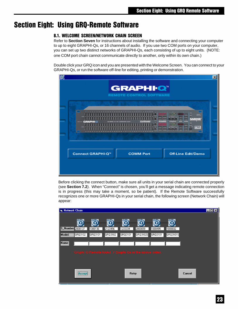
D$,$3�/��4�������1���3��.�6���������Refer to Section Seven for instructions about installing the software and connecting your computerto up to eight GRAPHI-Qs, or 16 channels of audio. If you use two COM ports on your computer,you can set up two distinct networks of GRAPHI-Qs, each consisting of up to eight units. (NOTE:one COM port chain cannot communicate directly to another, only within its own chain.)
Double click your GRQ icon and you are presented with the Welcome Screen. You can connect to yourGRAPHI-Qs, or run the software off-line for editing, printing or demonstration.
Before clicking the connect button, make sure all units in your serial chain are connected properly(see Section 7.2). When “Connect” is chosen, you’ll get a message indicating remote connectionis in progress (this may take a moment, so be patient). If the Remote Software successfullyrecognizes one or more GRAPHI-Qs in your serial chain, the following screen (Network Chain) willappear:

��
D$0$�)4���������The Main Remote screen (see page 26) is designed for easy access to all of the vital functions and controls ofthe GRAPHI-Q. Most can be accessed directly on the Main screen, and no control screen is more than a singlekeystroke away. If you’re familiar with Windows applications, you will probably be an expert with a few minutesof experimenting. Read on for a description of the control protocols for GRQ functions.
D$0$,$ ��C%�� �E����F �Changing EQ slider settings can be accomplished in three ways: (1) Click and drag the desired EQ slider withthe mouse; (2) Click the right mouse button, then type in the amount of boost or cut when prompted by a pop-up screen; or (3) Use the left-right arrow keys to navigate to the slider you desire (indicated in red), then usethe up/down arrows to boost or cut. All EQ adjustments allow a half-dB resolution, with one exception: in frontpanel mode with the EQ range set to +12 dB, the resolution for adjusting EQ faders will be 1 dB. In remote controlmode, however, the resolution for adjustment will always be ½ dB, regardless of EQ range. The value of thecurrent slider setting shows in a pop-up window whenever the slider is clicked with the left mouse button, orselected with a left-right arrow key.
A final extra control offered by the Remote Software is the level control slider to the right of the 31 EQ bands.This control is redundant with the gain knob on the compressor section of the Remote Software; changing onecontrol will be reflected in the setting indication of the other.
For two channel GRAPHI-Qs, click on the Channel selections to the right of the blue field to select the channelEQ controls you wish to adjust. For all GRAPHI-Q functions, the color yellow will represent all settings anddisplays associated with the left channel; green will represent the right channel.
Also to the right of the curve display are the controls that allow choice of EQ adjustment range (6 dB or 12 dBboost or cut).
D$0$0$ 6�"%1/�! ��� ���� ��High and Low Cut Filter Controls on the Remote Control are located just below the slider controls. Changinghigh and low cut filters can be accomplished by two methods:1. Click and drag on the left horizontal scroll bar to change the low cut filter, and on the right horizontal scroll
bar to change the high cut filter; or2. Click the right mouse button, and type in the filter value. Clicking with the left mouse button will also display
the current value of the filter. Filter slope can be independently set for both high and low cut filters by clickingon the slope indicators, located between the two horizontal scroll bars. Filter slope can be either 12 or 24dB per octave.
This screen shows all of the GRAPHI-Q units connected to your computer via serial connections from thedesignated COM port. (Remember the software will allow two separate chains of connected GRAPHI-Qs, usingtwo different COM ports.) It will also display the serial number of each unit, the model number, and a user-assignable name (Mains, Monitors, etc.). To assign a name, simply highlight the NAME box for the unit youwish to identify, then type in up to 8 characters. When you’ve done this for all the units you wish to name, orif you’ve already named units previously or don’t need any identification beyond serial numbers, click ACCEPT,and the software will open the main screen.
D$,$,$ � ����� ������� ������For first time startup with GRQ-3102 and 3101 ONLY: After you choose “Connect GRAPHI-Q” for the first time,the software will open in Front-Panel mode. This means that the front panel still has control, not your GRQsoftware. To take control with the software, follow these steps:
1. Choose Stored Presets from the Options Menu, or hit the F6 key.2. Click on “System Default”, then on “Load”.
This will enable your remote control, with all parameters set to the factory default. On all subsequent launchingsof GRQ-Remote, you will begin with the control mode that was in effect when the GRAPHI-Q was last turnedoff. NOTE: When GRQ Remote is in control, the REMOTE LED on the front panel will light.
If you are using the GRQ-3102S or 3101S, your first session will begin with GRQ-Remote in control. There isno front panel mode available with these models.
� �������"%������"�)� ��� ����!��

��
D$0$+$ � �C��� ���# ���C���The blue delineated field below the graphic EQ controls is the Response Curve Display. In default mode,this will show the totality of all EQ changes (graphic EQ, parametric EQ, high cut, low cut, FBX) mademanually or automatically to your audio signal, and currently in active mode, displayed separately for eachoutput (yellow = channel A, green = channel B). If any EQ function is in bypass, the Response Curve Displaywill NOT show the effect of that EQ (in other words, what you hear and what you see will correspond).
8.2.3.1. View Curve You can customize the Response Curve Display to show any or all of the various typesof EQ programmable with the GRAPHI-Q (the default mode is to show all EQ). Select View Curve fromthe Options Menu, or press F9 to access the screen at right:
You can elect to show the effect any combination of GRAPHI-Q EQ settings on your overall unit response curve, indepen-dently for any channel. Most commonly this selectabilitywould be used in order to view the response curve associatedwith only one type of EQ (e.g., FBX) in the signal path. Ourrecommendation is to display all EQ response, as this is thetrue “audio picture” of the GRAPHI-Q EQ settings, and willshow combined EQ results whenever a change is made.Otherwise, your response curve display may not reflect theactual EQ and filtering applied to your audio signal.
D$0$7$ ���C�� / # �To the right of the 31 graphic EQ sliders is the Output Level Control. This maybe adjusted in three ways: (1) Click and drag with the left mouse key; (2) Clickwith the right mouse key and type a value, or (3) Adjust the gain knob in theCompressor/Limiter section of the Remote Software main screen. Compres-sor Gain and Output Level Controls are redundant and will change together.
D$0$2$ �&5 � ���' �9� �������� G ����� ���� ���� ��The GRAPHI-Q Remote Control offers powerful options for setting andcontrolling FBX filters that are not available using front panel controls. Inaddition, the software allows programming of parametric EQ filters, which isnot possible from the front panel.
To access FBX/Parametric controls, click on the box to the right of the CurveDisplay labeled FBX/Parametrics, or press the F2 key, or choose “FBX &Parametric Filter” from the Main Menu. The screen shown on the followingpage will appear
After highlighting the TYPE field for any or all of the 12 filters for each channel,you can change the type of filter from FBX F (for fixed) to FBX D (for dynamic)to PARA (for parametric) using the left mouse button and the horizontal scrollbar located below the filter table. Alternatively, you may type F, D, or P (Note:the factory default is nine FBX F and three FBX D Filters). When PARA ischosen for a particular filter, you may then click on the FREQ, WIDTH, andDEPTH fields, and either type, or use the scroll bar, to select your desiredvalue. For two-channel GRAPHI-Qs, you may choose channels using theChannel A/Channel B selectors at the right of the FBX/Parametrics screen,where you will also find the controls for locking fixed filters (which will changetheir display readout from FBX-F to FBX-L), and adjusting global settings forGRAPHI-Q operation (details on these operations follow).
Active front panel GRAPHI-Qs under remote control will light their filter LEDswhenever an FBX filter sets, or when you change a filter type to a parametricfilter and choose a frequency, regardless of width or depth settings.
� �������"%������"�)� ��� ����!��
Keyboard Shortcuts
F2: FBX/Parametrics
F3: Comp/Limiter
F4: Digital Delay
F5: Global Parameters
F6: Stored Presets
F7: Contact ClosureAssignment
F8: Front Panel Defaults
F9: View Curves
F11: Link Table
F12: Reset Parameters
Ctrl-A: Select GRAPHI-Q #1
Ctrl-B: Select GRAPHI-Q #2Etc.
Shift-F1: Save snapshot #1
Shift-F2: Save snapshot #2
Shift-F3: Save snapshot #3
Ctrl-F1: Load snapshot #1
Ctrl -F2: Load snapshot #2
Ctrl-F3: Load snapshot #3
Escape: Closes currentscreen (except mainscreen)

��
ResponseCurve Display
Shows re-sponse curve of
allEQ filters
FBX and PARAMETRIC FILTERS SCREEN
MAIN GRQ REMOTE SCREEN
GLOBAL PARAMETERS SCREEN
Scroll Bar changesvalues in selected
field Click & drag thehandle, or click
anywhere in the bar forquick editing
Level IndicatorsInput, output,compressorgain/reduction,and limiterindicator for bothchannels
High CutSlider
Low CutSlider
Click to toggle EQboost/cut rangebetween ± 6 dBand ± 12 dB.
Graphic EQ linkindicator:1 line = Relative Link2 lines = Absolute Link
Parameter FilterLink Indicator
Global ParameterLink Indicator
Click to openscreens for theseparameters.
� �������"%������"�)� ��� ����!��

��
8.2.5.1. Setting FBX Filters with GRAPHI-Q Remote Software. The Remote Software offers an additionalmethod for setting FBX filters, as well as both Manual Turbo Mode and normal (non-Turbo) FBX setups,similar to front panel control options. The new software option is called Auto Turbo Mode. See section 6.3.1for more information about feedback filter and terminology. Also please read Section 6.4 for a morecomplete discussion of Turbo Mode.
For Remote Control op-eration, Manual or AutoTurbo Modes can only beaccessed by resetting allFBX filters in one or bothchannels (for two channelunits). If you have a 2-channel unit, and have re-set filters in both chan-nels, you will be asked toselect the channel for set-ting FBX filters in TurboMode. After FBX filtersare reset, the screen atright will appear:
Once you are familiar with Turbo options, you may move forward by clicking the appropriate selection.
If you are unfamiliar with Turbo Mode operation, click Turbo Help. The following screen will appear:
USING AUTO TURBO: Before selecting AUTO mode, make sure all your microphones are positioned, andturned up to the approximate correct gain setting for each input, while the master gain on your mixer is turneddown. Raise the master gain slowly (only for the appropriate channel for a 2-channel system) until you hearthe first hint of feedback, then click on AUTO. At this point, the GRAPHI-Q will take over, and slowly raiseits output gain, setting FBX filters sequentially as the gain increases. You will see the filters being set inthe FBX/Parametrics screen (the response curve will change and the actual frequency value of the feedbackwill be displayed) and a display of the amount of gain increase. Feedback will occur at a very low volume.Turbo mode will exit, and the gain will be dropped slightly (for a safety margin), when all fixed filters and thefirst dynamic FBX filter have been set, or when Turbo is turned off by clicking on the Cancel Turbo button.
� �������"%������"�)� ��� ����!��
NOTE: Channel A &B boxes appear onlywhen GRQ-3102 orGRQ-3102S modelsare connected.

��
For two-channel systems, AUTO TURBO will prompt you to perform the same setup for the secondchannel, or exit to normal operation. For models GRQ-3101 and GRQ-3102S, AUTO TURBO will set thesame filters simultaneously for both A and B outputs, and will show the B output FBX/parametric screenduring setup. You cannot set FBX filters in Output A if FBX/Parametric for Output B is bypassed beforesetup. Set filters first, then bypass B.
USING MANUAL TURBO: If you select MANUAL mode, the master gain must be raised manually (again,we recommend only one channel at a time for two-channel units). Raise the gain until the system is onthe verge of feedback, then walk around the stage with a microphone until you find a position that excitesfeedback. Slowly raise the gain to cause enough feedback to set an FBX filter. Repeat the process untilall of the FIXED filters and one DYNAMIC FBX filter are set. Then lower the gain slightly. During ManualTurbo operation, feedback will be kept to a low volume, and you will be able to see filters setting on boththe curve display, and in the FBX/Parametric screen. Manual Turbo Mode will exit when either the firstdynamic FBX filter is set, or when you click on the Cancel Turbo button. You’ll be prompted when ManualTurbo is exiting, and you may need to adjust system gain when TURBO is releasing and no longer limitingfeedback to a lower level (setup only). Be aware of the potential for any ringing feedback to briefly risein volume.
Gain Structure and Manual TurboIf your power amplifier gain is low, Manual Turbo Mode may not work well. The level of feedback iscompressed during Manual Turbo, and the combination of compressed output and low amplifier gainmay keep feedback below its threshold. Raise the amplifier gain to correct this. This situation cannotoccur in Auto Turbo Mode.
For two-channel systems, MANUAL TURBO will allow you the choice of either performing the samesetup for the second channel, or exiting to normal operation.
TWO CAUTIONS WHEN USING TURBO MODE:1. DO NOT USE TURBO DURING A PERFORMANCE. It is a setup tool only. If you play audio through
the GRAPHI-Q while it is in Turbo Mode (Manual or Auto), the audio may sound distorted, and FBXfilters will set inappropriately.
2. TURBO WORKS BEST IN A QUIET ENVIRONMENT. Because it relaxes its analysis of whatconstitutes feedback, Turbo mode may cause the GRAPHI-Q to set filters for any sound picked upby a microphone.
When in doubt, exit TURBO mode and ring out feedback by raising system gain. The results should beidentical, but feedback during setup will be louder.
NORMAL FBX OPERATION:After resetting FBX filters, if you close the Turbo setup screen, your GRAPHI-Q will still place FBX filterswhen feedback occurs. You can place filters without Turbo Mode simply by raising system gain untilfeedback occurs.
D$0$8$ ���C� ����1/���� � � ?���� ���Compressor/limiter controls are located below the EQ curve display on the main GRAPHI-Q remotescreen. You may adjust settings by clicking (left button) on a virtual knob or control and moving yourmouse, or by clicking with the right mouse button and typing in a value. In the former instance, a pop-up window will appear to show the changing parameter value as you make adjustments.
In addition, you may click the Compressor/Limiter button to the right of the Curve Display, chooseCompressor/Limiter from the Main Menu, or press F3. In each case, the screen shown at right will appear:
Within the Compressor/Limiter screen, you may change values for any of the seven compressor/limiterparameters (Ratio, Threshold, Gain, Attack, Release, Knee, and Limiter threshold) by clicking in the fieldand typing in a value, or clicking in the field and using the scroll bar at the bottom of the screen. For allparameters except Limiter threshold, you may also use the knobs at the bottom of the main screen. Allparameter value indicators (knob position, numeric indicator, and scroll bar position) will co-vary. Inaddition to these indicators, the Compressor/Limiter screen will graphically display the dynamicrelationship of input and output levels. (The front panel gain metering on the GRAPHI-Q will also reflectremote control settings.)
� �������"%������"�)� ��� ����!��

��
� �������"%������"�)� ��� ����!��
For GRQ-3102 and3102S models, youmay choose to haveyour compressor oper-ate in either True Ste-reo mode, or Dual Monomode. In Dual Monomode, the compressorfor each channel actsindependently. In TrueStereo mode, the twochannels interact to preserve stereo imaging, and a signal peak that exceeds the threshold in only onechannel will be compressed in both channels. The more extreme ratio setting of the two channels will bethe ratio applied to both signal paths as well.
Compressor mode is selectable by toggling the options in the box in the lower center section of theCompressor/Limiter screen. Note that stereo compression is distinct from linked compressor settings. SeeSection 8.3.2.5, Compressor Linking Options for GRQ-3102 and GRQ-3102S Models, for moreinformation on these options and how they affect compressor operation.
D$0$@$ ��"���� � ��� � ?���� ���Digital delay can be set from the main remote screen by two methods: (1) using the up/down arrow keysbelow the delay readout, or (2) right mouse clicking on the delay read-out, which will allow you to type andenter a delay value. For a more detailed look, you can access the Digital Delay Screen by either selectingDigital Delay from the Main Menu, or hitting the F4 key. The screen shown below will appear:
Inside the Delay Screen you may change the delay length by either using the horizontal scroll bar, orhighlighting a field and typing the desired value. Note that all three scales (time, meters, feet) changetogether. Front panel delay displays will update when values are changed using the Remote Software.
Caution: We recommend making largechanges in delay settings (or loadingpresets with large differences in delaysettings) only when audio is NOT playingthrough your system. Pitch shifting maytemporarily occur as delay is adjusted.You may bypass the delay section with-out pitch change occurring, but the timerelationship will change. In addition, toavoid “pops and clicks” in the audiosignal, digital delay changes are implemented in steps rather than all at once, and will take a bit longer tobe fully realized.
8.2.7.1. Temperature Gauge for Digital Delay The speed of sound changes as a function of ambient airtemperature. Therefore, the delay compensation required to synchronize the arrival of multiple soundsources (all at different positions) to a listener will vary as a function of temperature. The temperature gaugeallows you to measure the distance you are compensating for, and to adjust the corresponding delays asa function of ambient temperature. Simply set temperature in Fahrenheit or Centigrade scales, either byclicking in the temperature field and entering a value, or by clicking and dragging on the “mercury” in thethermometer icon. The relationship between distance and milliseconds will be automatically set to thecorrect proportion for the specified temperature.
D$0$D$ &�C���The GRAPHI-Q Remote Control software offers expanded control over various bypass functions. TheBypass controls are located at the bottom of the main screen, and are activated by clicking the appropriatebypass boxes. Active front panel units will display the appropriate bypass status as well.
The Remote Control allows all GRAPHI-Q processing to be bypassed individually by function and/or bychannel. Use Bypass to customize the processing you need on each GRAPHI-Q channel.
For GRQ-3102 and3102S models, thisbox on the compres-sor screen allowsthe compressor to beset to True Stereo orDual Mono operation.This option is notavailable for theGRQ-3101 or 3101Smodels.

�
D$+$/��.������4��������������/3��6�6��)*��4�������3���One of the most powerful features of the GRAPHI-Q Remote Software is its capability to control multipleunits from a single central computer. Up to two sets of eight units can be linked via serial cables andcontrolled from a single laptop computer.
Control of so many audio chan-nels can be greatly simplifiedby linking channels together,so that multiple channels maybe controlled by a single key-stroke. For example, if a soundsystem is using sets of identi-cal speakers in acousticallysimilar settings, one graphic EQcurve may be applicable to allthe audio channels, yet the dif-ferent speakers may requiredifferent delay settings. TheGRAPHI-Q offers an exception-ally easy and powerful methodof linking any number of chan-nels in various combinations.
Linking units is accomplishedvia the Link Table, which can beopened from the Options menu,or by pressing F11. The screenshown at right will open:
Let’s call each unit/channel combination (e.g., GRAPHI-Q #1, channel B) a “cell.” You may link cellsindependently for all of the displayed parameters; in other words, you can choose to link graphic EQ settingsfor one group of cells, and link delay settings for a completely different grouping. There are three availableconditions for linking cells:
· NO LINK Parameter settings are independent of all other channels and units. Changing the value ofa parameter for an unlinked cell will not affect any other cell (default condition).
· ABSOLUTE LINK Values of parameters for ABSOLUTELY LINKED cells will be copied to the identicalsetting. The first cell you choose for your ABSOLUTE LINK group will be the source value for copying,and will be highlighted with a red color. Once ABSOLUTE LINK is established, all linked cell settingswill change together when ANY of the linked cells is changed.
· RELATIVE LINK Value adjustments made to any REL LINKED cell will affect all REL LINKED cellsup or down by equal amounts. Initial differences among cells will be maintained. Since values arerelative, no one cell will act as a master or source value.
Using a combination of letters and numbers (A1, R2, A8, etc.), you may specify up to eight different linkedcombinations of cells for each parameter. For example, if you have 8 two channel GRAPHI-Qs in your serialnetwork, you could configure 8 linked groups, each linking together the two channels of each unit. Or, you
For single channel GRAPHI-Qs, bypass controls apply to the two different outputs of the unit. In addition tothe choice of Bypass or Active for each function for each output, you may set different values for delay timeand output gain for Outputs A and B.
CAUTION!: Be careful when bypassing FBX or Parametric filters. This may allow suppressed feedback tobe released!
Bypass settings are saved in Stored Presets and will be recalled as part of a saved preset. Bypass switching,however, is NOT subject to linked control (see next section).
� �������"%������"�)� ��� ����!��
�
could link all the A channels together for all 8 units, the B channels of the first four GRAPHI-Qs, the Bchannels of units 5 and 6, etc., or any combination up to eight different groups. All cells in the same linkedgroup must be either ABS LINKED or REL LINKED (e.g., cells labeled A1 and R1).
The links you program will not actually be applied to your GRAPHI-Q set up until you click APPLY atthe bottom left of the Link Table Screen.
When any parameters for outputs A and B for any GRAPHI-Q unit are linked (either ABS or REL), thiscondition will be indicated on all appropriate software screens. One or two lines—REL and ABSrespectively—will connect the appropriate channel indicators, with the main screen link indication reflectinglinking for graphic EQ controls only. See page 26 (top) for an illustration.
RANGE LIMITS If changing cell values within a REL group causes some or all of the linked cell valuesto reach and exceed the limits of available range, the initial offset will be reduced due to a “ceiling” (or “floor”)effect. Once all REL cells reach their limit, all initial differences will disappear, and the group will effectivelyact as an ABS group from that time forward.
D$+$,$ 6�! �� � � /��' ���C�Use F11 or the Options Menu to access the Link Table. Choose the parameter you wish to link, and choosethe first cell in your linked group. Highlight the cell with your mouse, then type either A1 (for ABS) or R1(for REL) and hit the ENTER key. Do the same for the other cells you wish to add to your group, then repeatthe process for additional linked groups, using the code A2, R2, etc., up to eight linked groups for eachparameter. NOTE: Whenever an ABS group is set, the FIRST CELL CHOSEN WILL ACT AS THE SOURCEVALUE TO BE COPIED TO ALL OTHER ABS CELLS WITH THE SAME NUMBER CODE. When you firstestablish your ABS group, this cell will be highlighted in red. After the initial linking, all values will be thesame.
D$+$0$ �C ���� /��'��" ����� �������8.3.2.1. GRQ-3101 and GRQ-3101S units. Both models of the Sabine GRAPHI-Q that offer one channelinput provide two independent outputs (see Section 5.5). This is a very useful feature that enables a singleinput unit to emulate two-channel operation, with additional control over the two outputs accessible with theSabine GRQ Remote Software. Two parameters (output level and digital delay) can be set to separatevalues for each of the two outputs (unless of course they are linked using the Link Table). All otherparameters (graphic EQ, high and low cut filters, parametric and FBX filters, compressor/limiter, and globalparameters) cannot be set independently for the two outputs for the GRQ-3101 or GRQ-3101S. In otherwords, these parameters are effectively ABS LINKED, and cannot be unlinked. Within the Link Table, thisspecial case is indicated by a gray shade in the B-channel cell for parameters except Output Level and DigitalDelay for all single input, dual output units in a serial chain. All linking that involves the A-channel for suchunits will automatically be applied to the B-channel as well.
8.3.2.2. Bypass Linking. Bypass/Active status for all parameters is NOT included under the control oflinked cells. In other words, bypass must be set for each channel of each unit manually. This affords moreoptions for independent control of the two outputs of single input units, since you may elect to applyprocessing or not to each output (even though the settings for the processing may not be changed for thetwo outputs). For example, you could set up two different EQ curves for each output of a GRQ-3101, byusing graphic EQ settings applied to one output (and bypassed in the second), and using parametric EQsettings for the second output (bypassing the first).
8.3.2.3. FBX Filter Linking. Since feedback involves an interaction of speaker and microphone, FBXfiltering is most accurate on a speaker-by-speaker, channel-by-channel basis. Linking FBX filters could endup applying filtering to one channel better suited to another. Therefore, FBX filters cannot be linked—eitherfrom one unit to another, or across same-unit channels for GRQ-3102 and GRQ-3102S models. For GRQ-3101 and GRQ-3101S models (one in and two out), FBX filters will be identical for outputs A and B. Youmay bypass FBX in either, both or neither of the outputs. You can set FBX filters independently for GRAPHI-Q outputs in a very short time.
� �������"%������"�)� ��� ����!��

��
8.3.2.4. Parametric Filter Linking. Parametric filters can be linked; however, different rules apply for GRQ-3102 and GRQ-3102S, as opposed to GRQ-3101 and GRQ-3101S.
For the GRQ-3102 and GRQ-3102S:1. The simplest case occurs when you begin by setting all the filters you wish to be linked FOR ALL LINKED
CHANNELS ON ALL AFFECTED UNITS to Parametric prior to any other manipulation (see Section8.2.5). If you desire a REL link, set the frequencies, depths, and widths to independent values, then usethe Link Table to create a REL LINK group. If you desire an ABS link, use the Link Table to create anABS LINK group. Note that FBX filters in place always take precedence over corresponding Parametricfilters in a linked network, to prevent unintentional removal of an FBX filter.
2. A more complicated scenario involves linking one channel to another without first setting correspondingfilter types on other channels or units to Parametric. You must manually change ALL filters you wish tolink to Parametric, and then change either width, depth, or frequency of any filter. The filter channel willact as the source value in an ABS link and its settings will be applied to linked parametric filters. In a RELlink, other linked channels will change up and down in equal increments, but need not have the same initialvalues.
For the GRQ-3101 and GRQ-3101S:You will not be allowed to have corresponding output filters set to different filter types. Changing one filter typefrom FBX-F to FBX-D to Parametric will automatically change the corresponding filter on the other output tothe same type of filter. All parameter changes will be identical for both outputs.
Section 8.3.2.5. Compressor Linking Options for GRQ-3102 and GRQ-3102S Models. Just as with anyother parameter setting, you may link compressor channels, left or right, within the same unit, or betweenmultiple units, in either ABS or REL linked networks. The procedure for this is identical as it is for otherparameters.
However, for stereo programs, simply linking compressor settings of the left and right channels to be identicalmay not be appropriate. For example, if both channel A and channel B begin to compress when a peak levelexceeds a certain threshold, and the sound engineer intentionally designs his audio program to have moresound in the left channel, that channel’s sound will be compressed more readily than the right channel program.Since compression affects sound levels, such a setup will result in a difference in the balance of left-rightchannel output levels relative to the input balance; in other words, the stereo image will shift.
To preserve channel balance yet still allow compression, Sabine offers another method of linking left and rightchannels of GRQ-3102 and 3102S models: True Stereo compression. In True Stereo mode, both channelsare compressed equally if the threshold is exceeded in either channel. There are two methods by which TrueStereo compression can be selected:1. In the Link Table, enter the letter “S” in the appropriate channel boxes, and click “Apply.”2. In the Compressor/Limiter screen, you may toggle the box below the CLOSE button to engage either True
Stereo or Dual Mono compressor modes.
Note that changing compressor link status by either method will automatically update the status report in theother screen.
True Stereo linking is subject to the following three conditions:1. It may not be applied to GRQ-3101 and 3101S models. Because these models do not offer two discrete
channel signal paths, True Stereo linking will not apply to such units.2. In a multiple unit GRAPHI-Q network, you may NOT apply a True Stereo link from one unit to another,
but only between the left and right channels of a single unit. All the units in a network may have their L-R channels linked, but each link will be independent of other units.
A 3102 or 3102S unit with channels linked in True Stereo may not also be part of an ABS or REL link forcompressor values. Of course other parameters may be linked (ABS or REL) independently of compressorrelationships.
8.3.2.6. Relative Linking and Scale Values. All changes made to cells that are REL LINKED will incrementor decrement by an identical number of steps in the scale of the parameter. This may not always be a linearrelationship. For example, changing the compressor ratio in one REL LINKED cell from 1:1 to 1.4:1 will resultin a change in another REL LINKED cell from 10:1 to 16:1. Both will move up one notch on the scale forcompression ratio scale.
� �������"%������"�)� ��� ����!��

��
8.3.2.7. Loading Memory Presets to Linked Units.If you try to recall and load a stored memory (see Section 8.6) to a unit with cells linked to any other unit,the screen shown at below will appear:
If you elect to continue, thevalue your loaded memory putsinto any linked cell on the cho-sen GRAPHI-Q will affect allother linked values as well. Ifyou don’t want this to happen,you must open the Link Tableand remove the appropriatelinking.
Loading a preset that changes a linked parametric or set-FBX filter back to an unset FBX filter will NOT loada corresponding filter change to linked channels. Linked channel FBX or parametric filters will remainunchanged unless your reset or manually program a change.
8.3.2.8. Resetting Parameters When Units Are Linked. (See also Section 8.4) Resetting any parameterfor any cell linked to another unit of channel will also change the value of all linked cells. For ABS LINK,all linked cells will be reset to the default parameter values. For REL LINK, parameter values for linked cellswill be decreased by the same amount as occurs by resetting the source cell. For example, resetting digitaldelay from 100 ms to the minimum value (1.38 ms) in the source cell will reduce all REL LINKED cells’ delaytimes by 98.62 ms.
For GRQ-3102 and GRQ-3102S models, REL LINK parameters can be reset separately or simultaneouslyfor each output. Whether channels are reset separately or together (checking either one or both channelboxes on the reset screen), the reset procedure for REL LINK will use the channel currently selected on themain screen as the source cell. IMPORTANT: When resetting REL, MAKE SURE THE CORRECTSOURCE IS SELECTED ON THE MAIN SOFTWARE SCREEN, if you are resetting just one output channel.
Note that FBX filters can be reset only one unit at a time. Parametric filters can be linked reset in ABS orREL groups, but the filters of linked units must correspond in position (filter #6, for example) and be set toParametric in order to be reset via linking.
Resetting parameter values for linked units, or loading presets to linked units, can create some complicatedscenarios. When in doubt, remove the relevant links, then restore after resetting.
8.3.2.9. Changing EQ Scale and/or High/Low Cut Filter Slope When Linked. For ABS LINK, changingthe graphic EQ scale (from 6 to 12 dB or vice versa) will also change the scale for all linked units’ graphicEQ settings. For REL LINK, all scales will not change when one unit’s scale is altered. Instead, all changesmade will be implemented proportionally according to scale. In other words, a change of 2 dB on a 12 dBscale will translate to a 1 dB change on a 6 dB scale. The same rules apply to variations in high and lowcut filter slopes, which can be set to either 12 or 24 dB per octave.
8.3.2.10. Front Panel Mode and Linking. Any GRAPHI-Q under front panel control CANNOT be part ofa linked network. Any GRAPHI-Q that is linked, then changed to front panel control, will be removed fromthe linked network. The unit will remain unlinked even if remote control is restored. You must use the LinkTable to restore linking to any unit after it is placed in front panel control and then returned to remote control.
8.3.2.11. Link Table Memory. The setup information for your link table is stored in an .exe file as part ofthe Remote Software, and is independent of the memory storage of parameters, etc., which are stored ineach individual GRAPHI-Q. Therefore, if you change your serial network setup by reconfiguring GRAPHI-Qs, changing the number of units, etc., your Link Table setup may no longer apply. For example, if youremove the middle unit in a 3-unit serial chain with Linking enabled, then reboot with only two units in yourserial chain, the Link setup for the “missing” second unit will be applied to the former third (now second) unit.As a precaution, a warning screen will appear at the next software startup whenever the number orarrangement of linked units has changed.
� �������"%������"�)� ��� ����!��

��
� �������"%������"�)� ��� ����!��
8.3.2.12. Speed of Command Execution in Linked Networks. Due to the limitations of the speed ofRS-232 communications, there may be some slight delays in command execution for a large networkof GRAPHI-Qs for units near the end of the chain. Most of this delay is a reporting delay; the commandwill be executed quickly, but the computer screen indication of the implemented change may take up toa few seconds. Speed is dependent on several factors:1. How “busy” each GRAPHI-Q is. Eliminating feedback, for example, is very processor-intensive
and will delay speed.2. The number of units in your serial network. The bigger the network, the longer the delay.3. The nature of the parameter under control. Digital delay, for example, is slower to respond than the
near-instantaneous response to graphic EQ change.
D$7$ ���������4�����You may use the Sabine Remote Software to reset all parameters, or a particular set of parameters. Toaccess the Reset Parameters, press F12Function Key, or select Reset Param-eters from the Options Menu at the top ofthe main remote screen. The screen atright will appear:
Use your mouse to click on the settingsyou wish to reset, or the “ALL” choice ifyou want to reset everything. For twochannel GRAPHI-Qs, you may reset set-tings for individual channels. For singlechannel GRAPHI-Qs, you may reset OUT-PUT LEVEL and DIGITAL DELAY set-tings for the two different outputs possiblewith these units; all other parameter set-tings are common to both outputs and willbe reset for both.
NOTE: Compressor output settings are NOT reset when the compressor /limiter parameters are reset.Output levels control the output gain of the GRAPHI-Q and must be reset separately.NOTE: If you want to compare your settings to the GRAPHI-Q default condition (all settings zero), thebest way to do this is to save your current setting to a Preset, then change between that Preset and Preset#0 (default).
D$2$����������6�*)��������������4��������All settings loaded into a GRAPHI-Q’s memory may be printed out for ease of documentation, by simplyselecting PRINT from the FILE menu at the top of the Remote Control main screen. Print one set ofparameters for each GRQ in a linked chain. Printing can be accomplished in
In addition to printing a record of parameter settings for an individual GRAPHI-Q, you may elect to printa record of how controls are linked for a multiple-unit GRAPHI-Q system. Simply select “PRINT” fromwithin the link table.
If you are out in the field and not attached to a printer, you can use the Off-Line Edit/Demo mode to printyour parameter and link-table files when you get back to the office. GRAPHI-Q parameter files can besent via e-mail as well — both to the office and from the office back to the remote location.

��
� �������"%��������"G� ������"�)�� � ��
D$8$�������������//���)�������
D$8$,$ 4 ���� �����" �� � ���� �C�����You may store and recall all settings of the GRAPHI-Q, either within the GRAPHI-Q memory itself, oras an external file.
8.6.1.1. Storage within the GRAPHI-Q memory. There are two methods of storing memories insidethe GRAPHI-Q itself:
1. using “Snapshot” memory storage. You may save and recall (load) up to three Snapshots ofGRAPHI-Q settings. Select Snapshot 1, 2, or 3 from the Options Menu, or use the keyboardshortcuts Shift/F1, Shift/F2, and Shift/F3. To recall Snapshots, select from the Options Menu, oruse keyboard shortcuts Ctrl/F1, Ctrl/F2, and Ctrl/F3.
2. accessing the Stored Presets screen. This will allow up to 65 additional user-specified memoryconfigurations to be stored. To open this screen, press F6 on your keyboard, or select Stored Presetsfrom the Options Menu. The following screen will open:
Preset 0 will always be the sys-tem default settings, effectively ablank template with all param-eters set to “off” or zero. Thisconfiguration will permit remotecontrol of the GRAPHI-Q fromany computer meeting the mini-mum requirements (see SectionSeven) with the GRAPHI-Q Re-mote Control for Windows Soft-ware installed.
Preset 1 (FRONT PANEL) willapply only to GRAPHI-Q modelsGRQ-3101 and 3102, and not tothe “S” (blank front panel slave)models. In this setting, the frontpanel controls of the GRAPHI-Q will provide the only means of controlling settings; any software-initiatedcontrols will be ignored. However, any adjustments made on the GRAPHI-Q front panel WILL bedisplayed on the Remote Control screens. In addition, any of these adjustments, alone or in combination,can then be saved to any of the memory locations from #2 to #66. To accomplish this, open the StoredPreset screen, and use the mouse to select the Program Number/Program Name field. Type in the nameyou wish to give your memory, then click on SAVE at the bottom of the screen. You can rename yourconfiguration without resaving all the parameter settings by typing a new name and pressing the ENTERkey.
If you save a program without naming it, the default name (e.g., Prog 1) will change to an all upper caseversion of the same name (e.g., PROG 1).Programs 2 through 66 will only allow remote control of the GRAPHI-Q, and front panel adjustments madewhen the remote control is in command will be ignored. However, loading Preset #1 will return controlto the front panel, and any physical adjustments made on the front panel while it was disconnected willbe implemented at that time.
When loading or saving configurations, the Stored Presets screen will stay open until you close it. Thisallows comparisons between different configurations by loading them to active memory and auditioningthe results.

��
� �������"%��������"G� ������"�)�� � ��
8.6.1.2. Summary of Stored Preset Protocols. To summarize the control and indicator protocols of theGRAPHI-Q:1. Whenever Preset 1 is selected, the front panel settings will be absolute indicators of parameter settings,
and manual adjustments will be implemented immediately. The Remote Control screens will display thesemanual adjustments, but remote control will be disabled. The Curve Display on your monitor will indicate“Preset #1 - Front Panel in Control”.
2. Any adjustments made manually from the front panel when Preset 1 is loaded may be stored and namedin any Preset from #2 to #66.
3. Presets 2 through 66 disable front panel control, in favor of Remote Control. All settings may be adjustedusing the Remote Control software only. Updated or altered settings may be stored (using the sameor a new name) in any location from #2 to #66.
4. For Presets 2 through 66, settings made by the Remote Control will be reflected by some but not allfront panel settings (on the actual GRAPHI-Q unit), but all WILL be displayed on the Remote Controlscreens. Adjusting the GRAPHI-Q front panel settings will NOT affect the audio signal, nor will theRemote Control screens reflect these settings.
5. Any preset may be stored or loaded at any time by opening the Stored Presets screen, selecting thedesired row, and clicking the SAVE or LOAD buttons at the screen’s bottom. Changing programs canbe done at any time, in the middle of an audio program if needed, PROVIDED THERE IS NOT A BIGDIFFERENCE IN DELAY SETTINGS FROM ONE MEMORY TO THE NEXT. Loading a new presetwith a different delay setting will cause a temporary pitch shift in the audio program if the change is madeduring program.
6. An X will appear to indicate last saved and last loaded presets. Clicking in the program name regionwill allow you to type in any name for your memory, up to 14 characters long. The number of the lastsaved and loaded presets will appear at the bottom of the main Remote Control screen.
7. The controlling interface (front panel or remote) will be indicated at the lower right of the main RemoteControl screen at all times.
8. See Section 6.7 for information about changing default values for front panel operation for parametersthat are not accessible without Remote Control.
8.6.1.3. Saving GRAPHI-Q files externally. Use the File Menu at the top left of the GRAPHI-Q main screenfor access to storage and recall of files to media (such as the computer hard drive, floppy disc, ZIP cartridge,etc.) external to the GRAPHI-Q. You may save and load such memories either as individual stored presets(Save Current Preset; Load Current Preset), or you can save and load up to 70 memories (65 user-defined,3 Snapshots, front panel, and default setting) as one entire “system file,” using the “Save Entire Set ofPresets” and “Load Entire Set of Presets” commands from the File Menu. When saving to a location outsidethe GRAPHI-Q itself, you’ll need to name the file or system file, and choose a storage location. The suffix“.grq” will be added to single program files, and the suffix “.gpd” will indicate system files. Note that savingor loading an entire system file may take a few minutes. You can track progress in loading/saving byobserving the progress bar in the lower left part of your screen.
D$8$0$ ������� ������ �!���% � ����By wiring and connecting a contact closure switch to the rear panel of your GRAPHI-Q (using theaccompanying Euro-block connector), and assigning presets to switch positions using the GRQ RemoteSoftware, you can create up to 127 different recallable configurations that can be loaded from internalGRAPHI-Q memory without a Remote Control interface. (Note: there are more preset locations than theGRAPHI-Q memory can hold, so some of these switch positions will have to load redundant presets).
8.6.2.1. Contact Closure Switch Wiring Switch wiring requires an 8-conductor cable. Attach these 8conductors to the 8-pin Euro or Phoenix block connector included with your purchase of the GRAPHI-Q. Thisconnector plugs into its mate in the back of the GRAPHI-Q chassis. The far left pin (as you look from theback) of the connection is the ground (common). The other end of the cable must be wired such that switchposition one grounds pin one, position two grounds pin two, etc. Different combinations of shortedconnections will provide up to 127 different recallable combinations.

��
� �������"%��������"G� ������"�)�����"��������
8.6.2.2. Assigning contact closure.Choose ASSIGN CONTACT CLOSUREfrom the Options Menu, or press key F7.The screen at right will appear.
The far right column allows you to assignstored preset numbers to each contactclosure switch combination. The switchdiagram at the bottom of the screen dis-plays the wiring combination that will loadthe corresponding GRAPHI-Q memory whenthe switch is changed to the correspondingposition. Note that switch position #1 willalways give control to the front panel knobsand sliders, if you are using either a GRQ-3101 or GRQ-3102 model. In addition, switch positions 8 through 127will default to front panel settings, until they are assigned other stored presets. All switch assignments forpositions 2 through 7, and any new assignments for positions 8 and above, will render the front panel controlsinoperative, until switch position #1 is chosen again. For GRQ-3101S and GRQ-3102S models, which do not havefront panel controls, switch position #1 will be disallowed, and switch positions 8 through 127 will remainunassigned until they are reprogrammed.
Note that initial contact closure switch assignments require the Remote Control software, but once assigned,presets and memories can be loaded into the GRAPHI-Q simply by choosing the appropriate switch position.Momentary contact is all that is needed to load a new memory into the GRAPHI-Q.
8.6.2.3. Contact closure changes with multiple units. In conditions where multiple GRAPHI-Qs are wired inparallel from a single contact-closure switch, ground loop problems can easily arise. To maximize your chancesfor problem-free operation, make sure all your audio connections are balanced (including downstream amplifierconnections), and that your GRAPHI-Qs are placed in the same equipment rack and derive power from the samecircuit.
D$@$���������4�����6����6�*)�You can assign any 8-character name to all of the GRAPHI-Qs connected to your computer. You can do this fromeither the Network Chain screen (see Section 8.1), or by choosing Reference Name Edit at the bottom of theOptions Menu. This latter action will open up a screen that will also display units, serial numbers, and names,which can be edited.
All assigned unit names will be displayed at the top of the Curve Display field on the Remote Software main screen.If no name has been chosen, the unit’s serial number will be displayed.
D$D$����3�������������3��6�)*��4�������3���
D$D$,$ ����!�� / # ��The GRAPHI-Q Remote Software offers 4 levels of security access to its controls, as follows:
ADMINISTRATOR. This is the highest level of security access, allowing full control over all GRAPHI-Qparameters, and the important unique ability to set passwords for access to all security levels. Separatepasswords can be set for ADMINISTRATOR, ENGINEER, and TECHNICIAN access.
ENGINEER. This is level 2, allowing full access to all controls, with the exception of setting passwords, whichcannot be done at ENGINEER security level. This would be an appropriate access level for a skilled systemoperator.
TECHNICIAN. This is level 3. A TECHNICIAN cannot change any GRAPHI-Q parameters, but can load presets.This might be appropriate access for a semiskilled system operator who needs to load different setups for differentapplications, but has limited understanding of GRAPHI-Q operation.
VISITOR. No password is required for VISITOR access to the GRAPHI-Q. At this level, the GRAPHI-Q willdisplay its current settings, but will be unresponsive to all commands. This level of access is appropriate forunauthorized or unsophisticated users.
Security access level will be indicated at the bottom of the main screen.
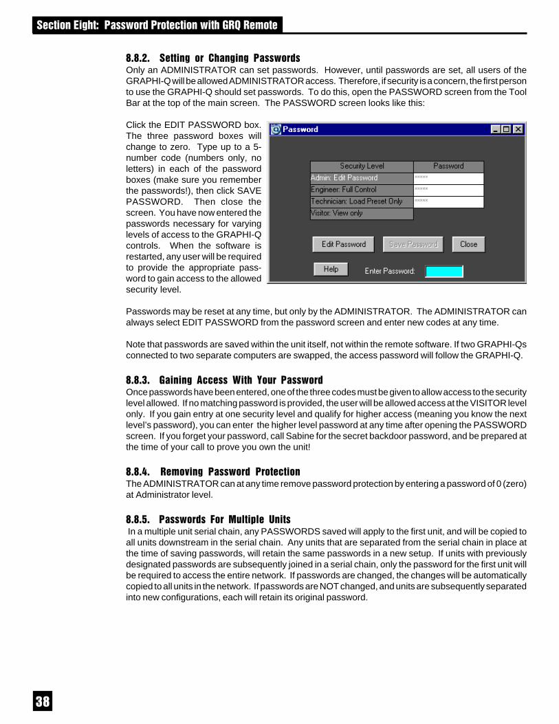
��
� �������"%������!�� ���� �����!��%�)� ���
D$D$0$ � ����" �� �%��"��" ����!�� �Only an ADMINISTRATOR can set passwords. However, until passwords are set, all users of theGRAPHI-Q will be allowed ADMINISTRATOR access. Therefore, if security is a concern, the first personto use the GRAPHI-Q should set passwords. To do this, open the PASSWORD screen from the ToolBar at the top of the main screen. The PASSWORD screen looks like this:
Click the EDIT PASSWORD box.The three password boxes willchange to zero. Type up to a 5-number code (numbers only, noletters) in each of the passwordboxes (make sure you rememberthe passwords!), then click SAVEPASSWORD. Then close thescreen. You have now entered thepasswords necessary for varyinglevels of access to the GRAPHI-Qcontrols. When the software isrestarted, any user will be requiredto provide the appropriate pass-word to gain access to the allowedsecurity level.
Passwords may be reset at any time, but only by the ADMINISTRATOR. The ADMINISTRATOR canalways select EDIT PASSWORD from the password screen and enter new codes at any time.
Note that passwords are saved within the unit itself, not within the remote software. If two GRAPHI-Qsconnected to two separate computers are swapped, the access password will follow the GRAPHI-Q.
D$D$+$ �����" ��� �� 3��% =��� ����!�� Once passwords have been entered, one of the three codes must be given to allow access to the securitylevel allowed. If no matching password is provided, the user will be allowed access at the VISITOR levelonly. If you gain entry at one security level and qualify for higher access (meaning you know the nextlevel’s password), you can enter the higher level password at any time after opening the PASSWORDscreen. If you forget your password, call Sabine for the secret backdoor password, and be prepared atthe time of your call to prove you own the unit!
D$D$7$ � ��#��" ����!�� ���� �����The ADMINISTRATOR can at any time remove password protection by entering a password of 0 (zero)at Administrator level.
D$D$2$ ����!�� � ��� 4����C� ����� In a multiple unit serial chain, any PASSWORDS saved will apply to the first unit, and will be copied toall units downstream in the serial chain. Any units that are separated from the serial chain in place atthe time of saving passwords, will retain the same passwords in a new setup. If units with previouslydesignated passwords are subsequently joined in a serial chain, only the password for the first unit willbe required to access the entire network. If passwords are changed, the changes will be automaticallycopied to all units in the network. If passwords are NOT changed, and units are subsequently separatedinto new configurations, each will retain its original password.

��
� �������"%���C"�� ��"���6�*)����!�� (������%��4
D$B$ ��(�����3��64�/���/������Here’s a quick guide to moving around rapidly from unit to unit when you are working with one computer andseveral GRAPHI-Qs.
SWITCHING CONTROL FROM ONE UNIT TO ANOTHER. This can be accomplished with either the pulldownmenu, “Select GRAPHI-Q,” or by the keyboard shortcut Cntr/A= unit #1, Cntr/B=unit #2, etc. The unit currentlyunder control will be displayed in the center top of the Curve Display on the main screen. You may switch fromcontrolling one unit to another with the Cntr key shortcut, no matter what screen (main or parameter screen) youare currently working in. This allows quick adjustments of the same parameters across all units in your serialchain.
D$,-$����������6�*)���43����������3���One more great feature of the GRAPHI-Q is its easy upgradability. Each units firmware (think of it as theoperating system) is stored in on-board FLASH RAM, which means you can upgrade the system by connectingyour computer to the Internet and loading in the latest firmware. In addition, you may download upgrades to theRemote Control software for the GRAPHI-Q.
This means your GRAPHI-Q can be updated easily and at no charge, right from your own home or office. Thisguarantees the GRAPHI-Q is a “future-proof” product and will offer state-of-the-art performance for years tocome.
You can determine your GRAPHI-Q’s current firmware version by one of three methods:1. For front panel models (GRQ-3101 or GRQ-3102), the firmware version will flash briefly in the digital delay
display immediately following power-up of your unit.2. For all models, the current firmware version will be stated in the "About" screen of the Remote Control
software (unit connected and powered up).
NOTE: If you have a slave unit (GRQ-3101S or 3102S) that will not connect to a computer for remote control,and you are not certain of the unit’s firmware version, contact the Sabine factory with the serial number of theunit. We can tell you the firmware contained when it left the factory.
When upgrading your GRAPHI-Q’s software or firmware, make sure you are upgrading to the latest releasedversion of each. At the time of this writing, the current release for firmware and software is version 3.10. Asnew features develop and upgrades are made, we will post these on our website and make them available fordownloading.
Earlier release versions include, for firmware, versions 1.10 and 2.10, and, for software, versions 1.16 and 2.10.Software and firmware versions must have the same number to the left of the decimal point in order to worktogether. Incompatibility problems may arise if you mix the wrong versions of firmware and software.
D$,-$, 6�! �� �C"�� =��� ����!�� On the CD ROM you received with yourGRAPHI-Q you will find the program calledSabine Upgrade Wizard. Install this pro-gram on your computer by running thesetup.exe file in the Upgrade Wizard direc-tory. Alternatively, you may download thelatest Upgrade Wizard program from theSabine website (www.SabineUSA.com).The program will place an icon on yourdesktop called “Upgrader.” Before you runthis program, you need to connect to theinternet using your usual connection pro-gram and internet service provider.
See the following page for step-by-stepinstructions on how to use the SabineUpgrade Wizard.

�
8.10.1.1. Downloading Sabine GRAPHI-Q firmware1. Go on-line using your Internet Service Provider (ISP).
2. Double click the Sabine Upgrader icon. The Upgrade Wizard dialog box will give you three choices:- Download the latest version of GRAPHI-Q firmware.- Upgrade GRAPHI-Q firmware.- Download the latest version of GRQ-Remote Software and install it on this computer.
3. Select the first option: “Download the latest version of GRAPHI -Q firmware” and click “Next>>.”
4. The Upgrade Wizard will connect to Sabine and then ask you to click “Next>>.” Do so.
5. You then will be given the opportunity to read the release notes for GRAPHI-Q firmware. Clicking“Read Release Notes” will open up your preferred Internet Browser to the document “Sabine GRAPHI-Q Firmware Release Notes” on Sabine’s website. If you elect to read this document, you can stillreturn to the Upgrade Wizard at any time. If you do not wish to read the update notes, click “Next>>”on the Upgrade Wizard.
6. The next screen allows you to register to receive notification by e-mail of future upgrades. This isoptional. Click “Next>>” to skip, or after you have entered your information.
7. Highlight the version of GRAPHI-Q firmware you wish to download and click “Download.”
8. The Upgrade Wizard will tell you when your download is complete. Click “Next>>” and you will returnto the first Upgrade Wizard screen.
8.10.1.2. Flashing your GRAPHI-Q(s) NOTE: This step is a continuation of the previous process butdoes not require being on-line. Make sure the serial port of your computer is connected to the Serial INon the GRAPHI-Q. If you have a multiple unit GRAPHI-Q setup in a serial network, you may update onlyone unit at a time. The unit being updated must be the first one connected, so you must connect andupdate each unit individually. Close all other programs, especially DOS programs.
1. On the first Upgrade Wizard screen, select the second option: Upgrade GRAPHI-Q firmware and click“Next>>.”
2. The screen will tell you that you must be connected to at single GRAPHI-Q. Make sure you areconnected and that the unit is OFF.
3. Select the COM port your GRAPHI-Q is connected to and click “Next>>.”
4. The next screen will tell you to turn on your GRAPHI-Q. The Upgrader will detect the GRAPHI-Qrebooting, erase existing firmware and then re-flash with the firmware file you downloaded fromSabine.
5. When the firmware has been installed, turn off your GRAPHI-Q and then turn it back on. The newfirmware will display briefly in the digital delay LED screen.
8.10.1.3. Note on Upgrading Firmware.Upgrading firmware from a CD ROM is a simple matter if you also use the same CD-ROM to install theSabine Upgrade Wizard that contains the latest software and firmware, or download the Upgrade Wizardfrom our web site. Once installed, the correct firmware will automatically be placed in a folder inside theUpgrade Wizard (default placement to C:/Program Files/Sabine/Sabine Upgrade Wizard). Default labelfor the firmware is “grq.bin.”
However, if you acquire new firmware (either from a CD or by download) independently of the SabineUpgrade Wizard (for example, if you already have the Upgrade Wizard installed on your computer beforeacquiring new firmware), you must place the new firmware inside the folder identified above, and renameit grq.bin. Once that is accomplished, you may proceed with the firmware upgrade procedure by checkingthe “Upgrade GRAPHI-Q firmware” choice on your Upgrade Wizard program (see 8.10.1.2. Flashingyour GRAPHI-Q(s) above). Following this procedure will insure that the firmware loaded into yourGRAPHI-Q is the latest and greatest.
NOTE: Upgrading the firmware does not interfere with your Stored Presets. This very powerful featureallows you to save all your hard work while you upgrade to all the most advanced features of the GRAPHI-Q operating system.
� �������"%���C"�� ��"���6�*)����!�� (������%��4

�
� �������� ���"" ����������C������� ���% ���6�*)Like any powerful tool, the GRAPHI-Q offers an infinite number of possible control configurations, andthe choices may at times appear overwhelming. Here are some helpful considerations for maximizingthe audio quality of your sound system, by taking advantage of the many powerful features of yourGRAPHI-Q.
B$,$�=���4��������������Long, long, ago, before the dawn of digital signal processing, sound engineers went bravely forth to theirgigs, armed more with knowledge than with electronics. Fortunately, we now have both knowledge ANDgreat tools like the GRAPHI-Q, but let’s review some nonelectronic considerations for optimal soundsystem setup. (Our apologies to those of you who already know this information...of course you’vealready quit reading!)
B$,$,$���������$You may not be able to build a bass trap in a boomy room, or convince a night club owner to carpet thedance floor. But if you are putting the GRAPHI-Q in a permanent installation, or your own rehearsal orproject studio, there may be some easy-to-implement ideas that will help the acoustics prior to theintroduction of amplification. Here are a few suggestions:
1. Ideally, a room with nonparallel, non-reflective surfaces that is large enough to accommodate a fullwave length (30 feet+) low bass frequency will provide you with fewer resonance points, a moreevenly balanced room response, and less feedback.
2. If you’re working in a less-than-ideal acoustical environment (like most of us), you might be able todo some simple acoustical treatment. Try to break up reflective patterns caused by hard, reflectivesurfaces by covering at least one surface with an absorbent material. Duct board (used to makeair conditioning ducts), made of compressed fiberglass, is cheap and works well...but be sure tocover the exposed fiberglass with fabric or carpet (fiberglass is nasty stuff). If you’re rehearsing ona cement garage floor, carpeting the floor will help both your feet and your ears (by cutting downon some of the boomy reflections).
3. The smaller the room you’re working in, the more the bass problem you’ll have. You might considerbuilding a bass trap to selectively absorb bass frequencies. Many of the current trade publicationsoffer advice on easy, inexpensive bass trap construction.
B$,$0$�E��C� ������ � ��If you’re moving your sound system around and can’t rebuild the room each time you move, or if you’reworking in an environment where you’ve done all you can to improve the acoustics, here are a few rulesof thumb that will help your system sound better:
1. Placement of speakers and microphones. Obviously, avoid when possible pointing microphonesdirectly at speakers, as this will optimize the likelihood of feedback. For the stage, it’s best if thehouse speakers are lined up at the front of the stage, and the microphones are set up further back.Be aware also that placing speakers close to the floor, wall, ceiling, or especially a corner, willreinforce the amount of bass energy heard from the speaker (you can alter the bass response ofyour system just by speaker placement!). Finally, aiming speakers so that they reflect sound froma wall or large object back into the microphone should also be avoided.
2. Microphone considerations. Directional (cardioid) microphones reduce sound coming from behindand beside them and are less likely to feed back than omnidirectional microphones (which pick upsound equally from all directions). Stationary microphones are less likely to feedback than mobilemicrophones (frequency response will change as a function of location; more locations means morevariety in frequency response, which means more frequencies can feed back). Finally, educatingmic users in proper mic technique will reduce the need to add gain when someone does not speakor sing in close proximity to the microphone.
3. Placement of your “mix position.” Ideally, you should set up your mix position out in front of the housespeakers, closer to one set of speakers (not in the middle if you’re sending sound out left and rightspeaker stacks), and not too close to a reflective room boundary like a wall. This will assure youof hearing sound directly from a speaker, uncolored by reflections or phase cancellation arising fromthe same sound reaching your ears at two different times.
� �������� ���"" ����������C������� ���% ���6�*)

��
A complete discussion of room acoustics, speaker and microphone placement, and so forth is obviouslyway beyond the scope of this manual. Likewise, a perfectly optimized acoustical space with an idealsound system is as rare as a humble lead guitarist. Fortunately, the GRAPHI-Q is an ideal tool forovercoming the shortcomings of the real world. Better sound through electronics is easy and affordable.
So far, the tips offered by this humble narrative are probably familiar to many people purchasing aGRAPHI-Q. Read on for some less obvious suggestions.
B$0$3�����������3��/��������6��H����4�����H����&5Here’s a trick question: how wide are the filters in a 1/3 octave graphic equalizer?
The answer to this question is not as obvious as the term “1/3 octave” would suggest. Much confusionstems from the fact that “1/3” refers to the center points of the frequencies on a graphic equalizer, NOTthe width of the filters. In practice, most audio manufacturers conform to an informal industry norm thatsets graphic EQ filters to a one- octave width.
This means that moving a graphic EQ slider up or down is notsurgically precise, as you are actually controlling a wide bandof frequencies, in a roughly symmetrical “bell curve” patterncentered on the nominal frequency. And since the width ofeach filter (one octave) is greater than the distance betweenadjacent graphic EQ center points (1/3 octave), this wide swathof filters that you’re controlling with one slider actually overlapsthe range of frequencies controlled by sliders to the right andleft. For example, cutting the 1000 Hz EQ slider will also affectthe 800 Hz and 1.25 Hz slider frequencies, to a lesser but stillsignificant degree.
The diagram at right illustrates the wide cut of a single graphic EQ slider. Is the industry standard choiceof filter width a good or a bad design? It depends entirely on the intended use of the equalizer in question.
There are at least two basic design intentions of equalizers, both of which are designed into the SabineGRAPHI-Q:
• SYSTEM EQUALIZATION. Equalizers are used to achieve a desired system response curve, bycompensating for acoustical resonances of a particular environment, and for the characteristics ofparticular audio gear (microphones, amplifiers, speakers, etc.). This kind of EQ is conducive to arelatively large number of filters of greater width, which facilitates achieving a smooth overallresponse. Narrow filter width produces more dramatic peaks and valleys in the response curve.
• “PINPOINT” EQUALIZATION. Equalizers are also used to correct very specific, relatively narrow-band problems or deficiencies in audio signals. Common examples would include audio hum inducedby AC electrical current (50 or 60 Hz plus harmonic multiples of those frequencies), or acousticalfeedback that arises when amplified sound is directed back into a microphone or pickup and re-amplified to the point of screaming oscillation. Using a wide, graphic EQ filter to correct hum orfeedback is overkill, since the filter is much wider than needed and unnecessarily affects frequenciesoutside the narrow “problem band.” Using a graphic EQ filter to reduce feedback thus has theunfortunate side effect of also subtracting a significant portion of the “good audio.” It’s like throwingthe baby out with the bath water.
In contrast to a graphic EQ filter, a PARAMETRIC filter affords a great deal of programmability. All the“parameters” of a filter can be specified precisely: Filter width, frequency, and dBs of boost or cut. Aparametric filter can be much more “surgically” applied to an audio signal, sometimes with such precisionas to be transparent to the listener, while correcting or improving the signal.
� �������� ���"" ����������C������� ���% ���6�*)

��
The patented Sabine FBX filter is essentially a parametric filter that is automatically activated whenacoustical feedback occurs. It is placed exactly at the frequency of the feedback, to the minimum depthnecessary to remove it, with a very narrow notch (typically 1/10 octave wide). The accuracy, narrowwidth, and minimum depth of the FBX filter means it can be placed with little or no adverse affect on thepurity of the audio signal. In fact, because audio system gain is often limited by the onset of feedbackas volume rises, FBX-equipped sound systems are both louder and clearer than systems that rely onalternative EQ filtering, or ignore feedback control altogether.
An additional very important benefit of the FBX algorithm is itsability to quickly and accurately distinguish feedback from audioprogram, allowing the automatic placement of filters duringperformance as well as setup.
Please note that graphic EQ and FBX filters are available usingthe front panel controls of your GRAPHI-Q. Parametric filters canonly be set using the GRAPHI-Q Remote Software, with an RS-232 connection made to a computer controller.
B$+$ ����44������)����
B$+$,$ � � �% ��C%�� �) �����Because of the considerations discussed above, Sabine recommends first adjusting graphic equalizationsettings, before addressing use of FBX or parametric filters. Graphic EQ filters will compensate foruneven system frequency response that arises from room acoustics and system components, with theultimate goal of producing a balanced sound.
What constitutes a “balanced sound” is of course a subject of endless debate. Suffice it to say thatmaking a system sound as good as it can is both a scientific and an artistic process. There are manywell-documented methods of optimizing your system, and useful measurement tools and techniques, butultimately the skill of the operator is the determining factor of sound quality.
So you may elect to adjust your graphic EQ settings purely on the basis of what sounds good to yourears, or you may opt to use a reference microphone and Real Time Analyzer to set your system EQ, oryou may combine these techniques.Here are a few suggestions that may prove helpful:
• SET THE RANGE. Before you make any adjustments, set your graphic EQ range to allow eithera ±6 dB or ±12 dB range of adjustment. The unit arrives from the factory preset to 12 dB range. Tochange to 6 dB, simultaneously press both the delay up and down buttons on the GRAPHI-Q frontpanel (for two channel units, either channel’s buttons will produce the same result). (NOTE: thistoggles the selection of 12 and 6dB ranges, and will switch back to 6 if you’re already set to 12).Whenever the range is set to 6dB the LED in the lower right corner of the front panel will light.
• BOOST = CUT. Try to balance the degree of frequency cut and boost when you make your graphicEQ adjustments. This will make before/after comparisons more accurate and meaningful; otherwise,whichever condition is louder overall may sound better to your ears and cloud your judgment.Additionally, due to the bell-shaped boost or cut characteristics of EQ filters, the more extreme theboost or cut, the more “ripple” (peaks or dips centered at the EQ slider frequencies) there will be inthe resultant system frequency response.
• VARY LEVEL AND LOCATION. If you’re making adjustments on the basis of what you’re hearing,listen to the system at various locations in the auditorium, and over a range of playback levels. Bothlocation and system gain can radically affect the perceived frequency balance.
� �������� ���"" ����������C������� ���% ���6�*)

��
• REFERENCE MICROPHONE. If you’re using a reference microphone and a Real Time Analyzer(such as those integral to the Sabine POWER-Q or REAL-Q2), you may also wish to study the resultswith the microphone at several locations. We recommend using a flat response, free-field referencemicrophone such as the Sabine SQ 1001.
• INTERACTIVE FADERS. Remember pushing up or down a range of filters is actually boosting orcutting beyond the range of any individual slider, because adjacent filters overlap and the settingsof each combine.
B$+$0$ ����" �&5 ���� ��Once your graphic EQ curve is set, you are ready to move on to setting FBX filters. Setting filters in thisorder (graphic before FBX) means you’re likely to get more benefit from your FBX filters. If there arefrequency ranges attenuated or boosted by your system or acoustics that are not first compensated forby graphic EQ, your FBX filters may cluster together, using several narrow filters to address a problembetter solved by one, wider filter, and more quickly exhausting available FBX filters.
B$+$+$ �%��"��" �&5 ���� �� �� ����� ���� ���� ��Using the remote control (see Section 8.2.5) you can change FBX filters to parametric filters. This allowsyou to manually change the width and/or the depth of the feedback filter set automatically. This may proveuseful if you set FBX filters and see that some have been placed close together. You may be able toprogram a parametric filter in between two filters with a slightly wider width or depth, and use one filterto do the job of two FBX filters. You can then reset FBX filters, rerun your setup, and get additional gainby adding another feedback filter to your arsenal.
� �������� ���"" ����������C������� ���% ���6�*)

��
B$7$���������/��/�=This section goes beyond the typical operating guide that only explains the front and back paneladjustments of a piece of equipment. Instead, we discuss the basic acoustical concepts needed to getthe most out of the use of digital delay in sound systems. If you are familiar with these principles, feelfree to skip ahead. Some principles may require additional delay channels and options available withthe Sabine DQX-206.
Why Digital Delays? The most intelligible sound occurs when two people speak face-to-face. Thesound is loud and dry, and the direction of the sound aligns with the speaker. The most intelligible soundsystems are the ones that come closest to emulating face to face communication. If this is your goal,a digital delay is essential to your sound system.
There are three distinct applications for digital delays. The first and most important is synchronizationof the loudspeakers to control excess reverberation and echo. Second, digital delays help controlcomb filter distortion, and finally, digital delays are useful for aligning the acoustic image so thedirection of the sound seems to be coming from the performer rather than from the loudspeaker.
B$7$,$ /�� �C �' � ����%����F�����Sound travels at about 1,130 feet per second in air, or about 1 foot per millisecond. On the other hand,electronic signals travel almost one million times faster through your sound system to the loudspeakers.The main task for digital delays is to synchronize multiple loudspeakers so the sound traveling differentdistances arrives at the listener’s ears at about the same time. Synchronizing the loudspeakers reducesreverberation and echoes for improved intelligibility.
9.4.1.1. How to Synchronize Your SignalsThere are several powerful tools available for precisely measuring the time a loudspeaker signal takesto arrive at a certain point in the audience. Most of these tools are very sophisticated and tend to bequite expensive. Fortunately, simpler tools are sufficient for most applications.
In the 1930s, engineers synchronized the low and high frequency speakers in movie theaters by feedinga sharp click through the system. They moved the speakers until they could only hear a single sharpclick coming from both speakers. You can use this same method with a common child’s toy called aclicker. Pressing the thin metal strip makes a loud sharp click. A clicker is especially useful whensynchronizing the direct sound from the performer with the sound from the loudspeakers.
Alternatively, you can use a phase checker especially for synchronizing the signals of two loudspeakers(either LF and HF or two full range systems) since most of the phase checkers include a click generatorand receiver. Phase checkers are quite affordable and have other uses besides synchronization.
9.4.1.2. Processing (or Group) DelaysConverting signals back and forth from the analog to digital domain always delays the signal a little.These conversion delays are often called processing (or group) delays, and usually range between 0.9and 5 milliseconds. You will notice that Sabine delays always display the processing delay as thesmallest possible delay value. For the GRAPHI-Q, the processing delay is 1.38 milliseconds. You canbypass the unit for 0 seconds delay.
Not all manufacturers acknowledge processing delays in their specifications, but you must take theminto account when synchronizing your system. Make sure all digital equipment is on and not bypassedwhen synchronizing. Also, be careful to make an appropriate adjustment in your delay lines if you lateradd any type of digital equipment to the system.
9.4.1.3. Center Cluster SpeakersCenter cluster speakers offer several advantages over systems that have speakers mounted on thesides. The most obvious advantage is that the distance to the closest and most distant locations in theaudience is often almost equal, so most listeners hear about the same level. Center clusters also offertwo other advantages regarding visual imaging.
� �������� ���"" ����������C������� ���% ���6�*)

��
Studies have shown that people can detect even small horizontal changes in the direction of a soundsource, but vertical shifts are much less noticeable. This suggests that the sound from center-clusterspeakers is more likely to be visually aligned with the performer than loudspeakers placed on each sideof the stage.
All those in the audience who are closer to the performer than the center cluster will hear the direct soundfrom the performer before they hear the sound from the loudspeakers. This makes the sound seem tocome from the performer, not the loudspeakers. (See the Precedence Effect on page 47.)
B$7$0$ ���� ���� � ����������Many who took high school science may remember ripple tank experiments where waves are generatedfrom two separate point sources. The waves from each source combine to form visible interferencepatterns. In some places the wave crests and troughs are in phase so they combined to make a largerwave. In other places the crests are out of phase, so the crest of one wave source is canceled by thetrough of the other. Ripple tank experiments show the interference patterns are strongest when theamplitudes of the waves from each source are equal.
A similar interference occurs in sound systems when a signal is delayed and mixed back into the originalsignal. These interference patterns are called COMB FILTERS because their frequency response plotslook like the teeth of a comb (see Delay Figs. 1 & 2). There are a number of common situations thatcause comb filters. For example, when the program is played through two loudspeakers, the loudspeakerthat is farther away interferes with the closer loudspeaker. Comb filters are also created when a performeris picked up by two microphones, one closer than the other. You even introduce comb filters by mixingdigital effects back into the “dry” signal at the mixer’s effects loop.
Delay Figure 1: COMB FILTERS.Input signal mixed with a 2 msec.delayed signal. (Both signals havethe same amplitude. Max. filter gainis +6dB, and max. depth is -4)
� �������� ���"" ����������C������� ���% ���6�*)

��
9.4.2.1. Calculating Comb Filter FrequenciesThe frequencies of the reinforcements and cancellations depend on the delay time (the time differencebetween the arrival time of the original signal and the delayed signal). The frequency of the first cancellationoccurs at 1/(2t) Hz, where t = the delay time in seconds. The cancellations are separated by (1/ t) Hz. DelayFig. 3 shows how the comb filters change with the delay time.
9.4.2.2. Comb Filter AmplitudeIf the original signal and the delayed signal are the same amplitude, the reinforced frequencies increase inamplitude by 6 dB, while the out-of-phase frequencies cancel completely to -4 dB.
Comb filters cause a lot of problems. The frequencies that are reinforced are prone to excite feedback, whilethe out-of-phase cancellations make the program sound thin and over equalized.
Try this simple experiment to hear what comb filters do to your sound.
Delay Figure 2: COMB FILTERS.Input signal mixed with a 2 msec.delayed signal. (Delayed signal has10dB less amplitude. Max. filtergain is +2.5dB, and max. depth is -3.) Reducing the amplitude of thedelayed signal reduces the combfilters' effect.
Delay Figure 3: Combfilters get closer as delaytime increases.
Delay Figure 4: Combfilters noticeably affectyour sound.
� �������� ���"" ����������C������� ���% ���6�*)
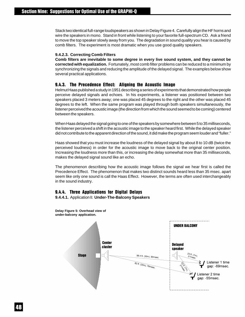
��
Stack two identical full-range loudspeakers as shown in Delay Figure 4. Carefully align the HF horns andwire the speakers in mono. Stand in front while listening to your favorite full-spectrum CD. Ask a friendto move the top speaker slowly away from you. The degradation in sound quality you hear is caused bycomb filters. The experiment is most dramatic when you use good quality speakers.
9.4.2.3. Correcting Comb FiltersComb filters are inevitable to some degree in every live sound system, and they cannot becorrected with equalization. Fortunately, most comb filter problems can be reduced to a minimum bysynchronizing the signals and reducing the amplitude of the delayed signal. The examples below showseveral practical applications.
B$7$+$ �% �� � �� ��� ��� ���"���" �% �������� ���" Helmut Haas published a study in 1951 describing a series of experiments that demonstrated how peopleperceive delayed signals and echoes. In his experiments, a listener was positioned between twospeakers placed 3 meters away; one was placed 45 degrees to the right and the other was placed 45degrees to the left. When the same program was played through both speakers simultaneously, thelistener perceived the acoustic image (the direction from which the sound seemed to be coming) centeredbetween the speakers.
When Haas delayed the signal going to one of the speakers by somewhere between 5 to 35 milliseconds,the listener perceived a shift in the acoustic image to the speaker heard first. While the delayed speakerdid not contribute to the apparent direction of the sound, it did make the program seem louder and “fuller.”
Haas showed that you must increase the loudness of the delayed signal by about 8 to 10 dB (twice theperceived loudness) in order for the acoustic image to move back to the original center position.Increasing the loudness more than this, or increasing the delay somewhat more than 35 milliseconds,makes the delayed signal sound like an echo.
The phenomenon describing how the acoustic image follows the signal we hear first is called thePrecedence Effect. The phenomenon that makes two distinct sounds heard less than 35 msec. apartseem like only one sound is call the Haas Effect. However, the terms are often used interchangeablyin the sound industry.
B$7$7$ �%� �CC��������� ��� ��"���� � ����9.4.4.1. Application I: Under-The-Balcony Speakers
Delay Figure 5: Overhead view ofunder-balcony application.
� �������� ���"" ����������C������� ���% ���6�*)

��
Delay Figure 5 shows a typical situation where the performer is amplified by a center cluster hangingabove the stage. Almost everybody in the audience will enjoy good sound, except those seated in theshadow of the balcony. So we add an under-balcony speaker to fill in the shadow.
Now we have sufficient volume under the balcony, but the sound from the two speakers arrives at thelistener’s ears some 55 to 69 milliseconds apart. The two signals, along with their echoes, result in anunintelligible cacophony. We must delay the sound from the under-balcony speaker to synchronize thesignals. Do we set the GRAPHI-Q delay to 55 or 69 milliseconds? Obviously, the geometry will not allowus to exactly synchronize every location under the balcony; we have to compromise.
First, consider the program type. For spoken word programs, you will produce the best intelligibility ifthe signals from the under-balcony speakers arrive within 10 msec. of the signals from the center cluster.Therefore we should set the delay to 65-69 msec. You can allow a little more reverberation for programsthat are mostly music.
Next, we must eliminate comb filter distortion. Find the axis where the levels of the center cluster andunder-balcony speaker are equal. (See "Comb Filter Distortion," p.45.) You can use the GRAPHI-Q toprecisely synchronize the speakers along this axis to eliminate the most severe comb filters. Comb filtersoff the equal-level axis are much less of a problem since a louder signal is not affected very much bya weaker signal.
Finally, you can experiment with adding 5 to 10 milliseconds delay to both sets of speakers to enhancethe Precedence Effect for the audience seated near the performer.
In the final analysis, every setting is a compromise, and your ear has to be the final judge. Check thesound in several different locations throughout the auditorium and correct the most severe irregularities.
9.4.4.2. Application II: Center Cluster with Front FillsDelay Figure 6 below describes a typical application that has a stage with a microphone, a center clusterabove the stage, and front fills in front of the stage. There must be thousands of installations throughoutthe world like this that "get by" without digital delays. But with the GRAPHI-Q, you can improve theintelligibility and add a new quality without ringing up any significant costs. Use the GRAPHI-Q in thissituation to align the visual image with the acoustic image. The program is much more enjoyable whenthe amplified sound seems to be originating with the performer, not the loudspeakers.
Delay Figure 6: Synchronizingcenter clusters and front fills.
� �������� ���"" ����������C������� ���% ���6�*)

�
Find a central place in the audience where the center cluster is 6 to 8 dB louder than the direct soundfrom the performer. Delay them so that their sound arrives 5 to 8 milliseconds after the direct soundfrom the performer. Experiment by bypassing the GRAPHI-Q in and out to hear how the source of thesound seems to move from the loudspeakers to the performer and back. Now your ears have the samedirectional information as your eyes, so the performance will sound more natural and exciting. Thebest seats in the house just got better.
What about the front fills? Their purpose is to add intelligibility and listening comfort to the first few rowsnearest the stage by filling in the areas missed by the center clusters. Add about 8 msec. to the frontfills to take advantage of the Precedence Effect.
The 8 msec. setting presumes the performer is standing on the front few feet of the stage. But somestages are well over 30 feet deep. What if there is a second performer standing 25 feet behind the first?The direct sound from his or her voice will reach the first few rows about 25 msec. after the firstperformer's. The audience will perceive the first performer directly and the second performer throughthe loudspeakers.
We can add the advantage of the Precedence Effect to the second performer by placing the GRAPHI-Q in the mixer's channel insert point and adding a 25 msec. delay.
Certainly taking advantage of the Precedence Effect is not as obvious to the audience as eliminatingfeedback, but it is nice to know you did all that is possible to make the performance enjoyable.
9.4.4.3. Application III: Synchronizing the signals of a far-throw and short-throw loudspeaker.In order to reach the proper coverage in larger venues, we often stack two full range speakers - a short-throw center cluster for the audience below and a far-throw speaker for the back of the auditorium. Itis almost impossible to perfectly align the stacked speakers mechanically, so comb filter distortionbecomes a problem in the area where the levels from both speakers are equal. The same thinghappens with speakers mounted on the right and left sides.
It is impossible to remove comb filters with equalization, but the GRAPHI-Q eliminates them in shortorder without affecting the spectral balance for the rest of the audience. Find the axis where the levelsfrom the two speakers are equal. This is where the comb filters are most severe. Carefully adjust theGRAPHI-Q so that the signal from both speakers arrives at precisely the same time. The GRAPHI-Q provides 20 microsecond resolution for this purpose.
Use the same procedure to align speakers within a cluster when necessary.
Delay Figure 7: Aligning far-and short-throw speakers.(The level from bothspeakers is equal.)
� �������� ���"" ����������C������� ���% ���6�*)

�
B$2$�����6���4�������1/�4����The dynamic range (how loud we can hear to how quiet a sound we can detect) of the human ear is fargreater than the capacity of sound systems to reproduce. Although some of this equipment limitationis at the upper extreme of the dynamic range (where too loud a signal will produce distortion), much ofthe restriction occurs at the low level end, where the signal disappears below the “noise floor” of thecircuitry.
A compressor (or in its most powerful form, a limiter) is the most widely used tool for controlling dynamicrange. In the simplest terms, a compressor is designed to restrict the dynamic range of an audioprogram; i.e., to make quiet signals louder, and loud signals quieter. A compressor becomes a limiterwhen the compression ratio (the ratio of the input gain change to the output gain change) is so high thatthe output level won’t rise above a “brick wall” ceiling regardless of how loud the input gets.
A compressor acts like an “automatic mix engineer” with a hand on the fader, and an inhumanly fastreaction time. When the input level increases, the engineer drops the fader; when the level decreases,the fader is raised. If the amount of fader compensation equals the variation in signal level, the outputlevel of the audio program will sound consistent.
The practical benefits of compression include:
1. Speaker protection. A compressor will control sudden level peaks and prevent your speakers fromdamage.
2. Perceived increase in loudness. Because peak levels are kept from rising as high as uncompressedsignals, you gain headroom for your audio program and can raise its overall average gain.Compression is often added to the entire audio mix, both in live sound and recording, to increaseits perceived loudness.
3. Mix consistency. For expressive instruments or vocals, which may have a large dynamic range,compression can help maintain consistent mix levels. So a vocal that varies from a whisper to ascream will not disappear or stand out in the mix, relative to other less dynamic instruments.
Like any signal processing, compression can be misused, and cause undesirable problems in the audiosignal. Some of these problems include:
1. Noise. If the threshold for compression is set too low, and the output gain is raised substantiallyto make up for the gain loss of compression, the resulting output signal can be noisy. This is becausethe input signal must be raised significantly to produce the same output level, and the noise floorof your equipment will be amplified unnecessarily. This problem will be exaggerated if the inputsignal level to the compressor is very low (which will already degrade the signal-to-noise ratio).
2. Breathing. In situations where the compression ratio is high, the threshold is low, and the releasetime of the compressor is short, the noise floor will modulate up and down as the audio signal stopsand starts.
3. Pumping. When the compressor release time is set too long, low level signals that follow a peakclosely will disappear or fade back up as the compression releases. Experiment with the releasetime to obtain the ideal setting; this will be a function of the program content.
4. Over-compression. Applying too much compression to a mix can sometimes result in such evened-out dynamics that the “life” of the music has been removed or curtailed. Dynamic variation in musicis a major component of its excitement and interest; don’t remove them, just control them. This maybe particularly true for percussive sounds such as drums. While compressing drums can “fatten”up the sound, setting the attack time to be longer may allow the initial strike of the drum to have moreimpact.
� �������� ���"" ����������C������� ���% ���6�*)

��
B$2$,$ ��"" �� ���C� ���� � ����"�VOCAL COMPRESSION. The renowned expressive-ness of the human voice is due in large part to itsdynamics. A vocal that varies from a whisper to ascream has a strong emotional impact, but those samedynamics present a challenge to the sound engineer.Ideal vocal compression maintains some dynamic range while keeping the vocal the focal point of themix.
(Ratio set to 4 or 6:1; threshold set so vocal peaks are compressed about 4-6 dB, attack and releaseshould be fairly quick; gain makeup boosted slightly to compensate for gain reduction, soft knee).
DRUM COMPRESSION. Compressing drums addpunch and fullness to their sound, and also tend to makelevels of individual drum hits more uniform. Care shouldbe taken to avoid squashing the attack of the drum toomuch. Slowing down the attack time of the compressorwill allow more of the stick impact to be heard. You may elect to compress drums individually, or submixvarious drum mics through a compressor, to be fed back into the mix along with the uncompressed drummix.
(Ratio set to 3- 6:1, threshold catches all hits, medium attack, quick release; gain makeup boostedslightly, soft knee).
BASS GUITAR. Bass players use a variety of tech-niques, often in the same song, that can benefit fromcompression. Compressing bass evens out peaks andkeeps the bass level in the mix.
(Ratio set to 4:1, threshold set to compress peaks only, quick attack, medium release, hard knee, outputboosted slightly)
GUITAR. A high compression ratio (with gain makeup)will add sustain to held notes and chords. Moving thethreshold will change the audible thick/thinness of theguitar tone, but generally you want to compress all thenotes played. As with drums, be wary of too quick anattack, which may reduce the percussive attack of the guitar notes. Be wary of too much gain makeup,and too high a compression ratio, which may make a noisy guitar amplifier more objectionable.
(Ratio set from 6 to 20:1, threshold variable, slower attack, soft knee, output gain boosted slightly tosignificantly depending on amount of compression. Try various release settings, depending on the speedof notes played.)
ENTIRE MIX. It’s quite common to compress the entiremix, both live and in the studio. This elevates theaverage level of the mix, resulting in an apparentincrease in volume.
(Ratio set to 2 or 3:1, threshold set to compress peaks, medium attack, soft knee, output boosted slightly)
� �������� ���"" ����������C������� ���% ���6�*)
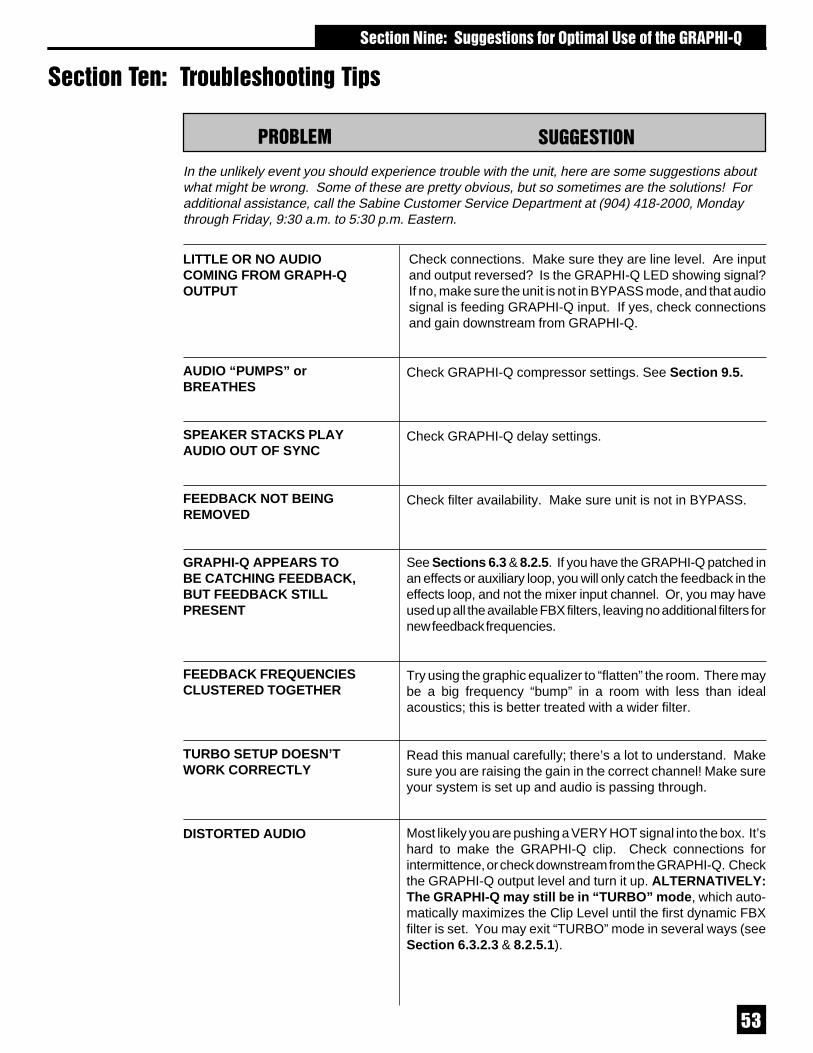
��
� ������ �������� �%�����"��C�
In the unlikely event you should experience trouble with the unit, here are some suggestions aboutwhat might be wrong. Some of these are pretty obvious, but so sometimes are the solutions! Foradditional assistance, call the Sabine Customer Service Department at (904) 418-2000, Mondaythrough Friday, 9:30 a.m. to 5:30 p.m. Eastern.
Most likely you are pushing a VERY HOT signal into the box. It’shard to make the GRAPHI-Q clip. Check connections forintermittence, or check downstream from the GRAPHI-Q. Checkthe GRAPHI-Q output level and turn it up. ALTERNATIVELY:The GRAPHI-Q may still be in “TURBO” mode, which auto-matically maximizes the Clip Level until the first dynamic FBXfilter is set. You may exit “TURBO” mode in several ways (seeSection 6.3.2.3 & 8.2.5.1).
LITTLE OR NO AUDIOCOMING FROM GRAPH-QOUTPUT
AUDIO “PUMPS” orBREATHES
SPEAKER STACKS PLAYAUDIO OUT OF SYNC
FEEDBACK NOT BEINGREMOVED
GRAPHI-Q APPEARS TOBE CATCHING FEEDBACK,BUT FEEDBACK STILLPRESENT
FEEDBACK FREQUENCIESCLUSTERED TOGETHER
TURBO SETUP DOESN’TWORK CORRECTLY
DISTORTED AUDIO
Check GRAPHI-Q compressor settings. See Section 9.5.
Check filter availability. Make sure unit is not in BYPASS.
See Sections 6.3 & 8.2.5. If you have the GRAPHI-Q patched inan effects or auxiliary loop, you will only catch the feedback in theeffects loop, and not the mixer input channel. Or, you may haveused up all the available FBX filters, leaving no additional filters fornew feedback frequencies.
���&/�4 ��������
Check connections. Make sure they are line level. Are inputand output reversed? Is the GRAPHI-Q LED showing signal?If no, make sure the unit is not in BYPASS mode, and that audiosignal is feeding GRAPHI-Q input. If yes, check connectionsand gain downstream from GRAPHI-Q.
Try using the graphic equalizer to “flatten” the room. There maybe a big frequency “bump” in a room with less than idealacoustics; this is better treated with a wider filter.
Check GRAPHI-Q delay settings.
Read this manual carefully; there’s a lot to understand. Makesure you are raising the gain in the correct channel! Make sureyour system is set up and audio is passing through.
� �������� ���"" ����������C������� ���% ���6�*)

��
Bypass the GRAPHI-Q. If noise is still there, it’s not theGRAPHI-Q. If noise goes away, check your gain structure.Make sure the input level to the GRAPHI-Q is robust. Turn downgain downstream.
Is your GRAPHI-Q in front-panel mode? Load any StoredPreset other than #1.
Check output level. Most likely you are mixing balanced andunbalanced connections, which lowers gain 6 dB.
Either your unit is (or was) connected to GRQ-Remote orswitched via contact closure, and the front panel is disabled.Resume control via GRQ-Remote or contact switch. In a pinchshort the extreme left & right pins of the back panel contactconnector.
Parametric filter linking obeys a set of rules that will make itdifficult for you to accidentally defeat an FBX filter already inplace. See Section 8.3.
The GRAPHI-Q software requires that your computer displayfonts be set to “small.”Click the “Start” button and select “Settings” and “Control Panel.”Double-click “Display” and select “Settings,” then click the“Advanced...” button. Select “Small Fonts” and then OK to all.Restart your computer.
���&/�4 ��������
NOISY AUDIO
FRONT PANEL CONTROLSDON’T WORK
REMOTE CONTROL DOESN’TWORK
SIGNAL LOSES GAIN GOINGTHROUGH GRAPHI-Q
PARAMETRIC FILTERS DONOT LINK
REMOTE SOFTWARE SCREENDISTORTED, LETTERS DO NOTFIT CORRECTLY
� ������ �������� �%�����"��C�

��
� ������� # �����6�*)��"�� ���"�C ����������������/���������
24 bit A/D and D/A32-bit DSP
���6���)��/�:��
31 digital filters on 1/3-octave ISO center frequencies, width adjust-able¨ from 0.5 to 1.0 octave in .01 octave increments; ±12 or 6 dBboost and cut
±6 or 12 dB boost and cut rangeIndependent display and control of A & B channels
�&51����4����� ��/����
Twelve independent digital filters per channel, controlled automati-cally or parametrically from 20 Hz to 20 KHz, each switchable (GRQRemote) between FBX fixed filters, FBX dynamic filters, and para-metric filters¹
Filter depth: user-controllable in 1 dB steps from +12 dB to -84 dB(parametric mode); 3 dB steps from 0 dB to -80 dB (FBX mode), max.FBX depth adjustable from -6 to -80 dB
Filter width: user-controllable from 9.99 to .01 octave (parametric),1.0 to .01 octave (FBX*)Low Cut Filter, user-controllable between 20 Hz and 1 KHz; 12 dB/octave roll-offHigh Cut Filter, user-controllable between 3 KHz and 20 KHz; 12dB/octave roll-off
Resolution: 1 Hz from 20 Hz to 20 KHz, FBX & parametric modeTime required to find and eliminate feedback: typically 0.3 seconds@ 1 KHz
Total number of combined filters active per channel: user-select-able, 0-12; plus low and high cut filters
�����/ ��4�������1/�4����
Threshold: +32 dBV to -30 dBV peak in 0.5 dB steps
Ratio: 1:1 through infinityKnee: variable soft/hard¨Attack: 1 to 99 msec in 1 msec steps¹
Release: .05 to 5 sec in .05 sec steps¹Peak limit threshold: +32 dBV to -30 dBV peak in 0.5 dB steps¹
�����/ ��/�=
1.38 to 999.96 msec in 20 µsec steps
Programmable in milliseconds, feet or meters
����3���������������
4 levels¹
������/�
GRQ-3102, 3101: Front panel, GRQ Remote (RS 232), RemoteswitchingGRQ-3102S, 3101S: GRQ Remote (RS 232), Remote switching
��(�G����//�������������I
68 user defined
1 factory default1 most recent configuration (power down save)1 front panel
�����1������JJ
Input impedance: Balanced > 10K Ohms, PIN 2 highOutput impedance: Balanced 50 Ohms nominal, PIN 2 high
Input/Output maximum signal levels: Balanced +29 dBV peakMaximum output load: 600 Ohms balancedBypass: true power-off bypass
I/O connectors: XLR-3, 1/4" TRSGRQ-3102 and 3102S: Dual channel, one input, one output perchannel
GRQ-3101, and 3101S: Single channel, one input, two outputs.Functions on each output selectable via GRQ-Remote
������4����K
Frequency response: 20 Hz to 20 KHz, ±0.3 dB dB @ +22 dBV
THD: <0.01% at 1.0 KHz at +22 dBV with 30KHz bandwidthSNR***: >105 dB (with ClipGuardTM)Dynamic Range: >110 dB (with ClipGuardTM)
Headroom: +22 dB @ 4 dBV nominal input (balanced)
�������
Operating system firmware stored in FLASH RAM. All futureupgrades for firmware and software downloadable from Sabinewebsite using GRQ Remote.
��3��
50/60 Hz available in 100 V, 120 V, 230 V; 20 W
��4�������
2-U rack mount 19 x 3.5 x 9 in. (48.3 x 9 x 22.9 cm); 9 lb. (3.9 Kg)
1-U rack mount 19 x 1.75 x 9.5 in. (48.3 x 4.5 x 22.9 cm); 8 lb. (3.6Kg)
* Below approximately 200 Hz the feedback filters become slightlywider to increase the feedback and rumble capture speed at theselow frequencies.** Inputs may be balanced or unbalanced. For maximum outputcapabilities, outputs must be balanced (XLR or TRS). If either sideof an output is grounded, the peak and output dynamic range willbe reduced by 6 dB.
*** Signal-to-noise ratio is the ratio of the maximum undistortedsignal by specification (26 dBV RMS sinewave) to the noise floor¹ Available using GRQ Remote Software only2 Tests performed using an Audio Precision System One model322 or equal
All GRAPHI-Qs conform to all Year 2000 (Y2K) standards.(SPECIFICATIONS SUBJECT TO CHANGE WITHOUT NOTICE.)
� ������� # ����"�� ���"�C ��

��
Warning! This equipment must be earthed.Caution! Risk of electric shock. Do not open.Caution! Shock hazard. Do not remove covers. No user serviceable partsinside. Refer servicing to qualified service personnel.Warning! To reduce the risk of fire or electric shock, do not expose this productto rain or moisture.
Attention! Cet appareil doit être relié à la terre.Attention! Risque de choc électrique; ne pas ouvrir.Attention! Risque de choc; ne pas oter les capots. Aucune pièce accessible àl'intérieur. S'addresser à un technicien qualifié.Attention! Pour réduire le risque d'incendie ou de choc électrique, ne pas laisserl'appareil sous la plouie ou à l'humidité.
Achtung! Dieses Gerät muss schutzgeerdet sein.Achtung! Gefar eines elektrischen Stormschlags. Gehause nicht öffnen.Achtung! Gefar eines elektrischen Stormschlags. Gehäuse nicht öffnen. Keinecon Benutzer zu bedienenden Teile im Geräteinneren.Überlassen Sie das Gerät zu Servicezwecken nur geschultem Fachpersonal.Um Brandgefar oder das Risiko eines elektrischen Schlags auszuschließen,das Gerät vor Nässe und Feuchtigkeit schützen.
Advertencia! Este equipo debe estar conectado a tierra.Precaución! Reisgo de descarga eléctrica. No abrir.Precaución! Riesgo de descarga eléctrica. No desmontar las tapas. Piezasinteriores no reparables por el usuario. Reparable sólo por personal cualificado.Advertencia! Para reducir el riesgo de incendio o de descarga eléctrica noexponga este producto a la lluvia o humedad.
FCC Statement:This device complies with Part 15, Class B, of the FCC Rules. Operation issubject to the following conditions: (1) This device may not cause harmfulinterference; and (2) This device must accept any interference received,including interference that may cause undesired operation. Warning: Changesor modifications to this unit not expressly approved by the party responsible forcompliance could void the user's authority to operate the equipment.
NOTE: This equipment has been tested and found to comply with the limits for aClass B digital device, pursuant to Part 15 of the FCC Rules. These limits aredesigned to provide reasonable protection against harmful interference in aresidential installation. This equipment generates, uses, and can radiate radiofrequency energy and, if not installed and used in accordance with theinstructions, may cause harmful interference to radio communications.However, there is no guarantee that interference will not occur in a particularinstallation. If this equipment does cause harmful interference to radio ortelevision reception, which can be determined by turning the equipment off andon, the user is encouraged to try to correct the interference by one or more ofthe following measures:
•Reorient or relocate the receiving antenna.•Increase the separation between the equipment and receiver.•Connect the equipment into an outlet on a circuit different from that to which the receiver is connected.•Consult the dealer or an experienced radio TV technician for help.
This digital apparatus does not exceed the Class B limits for radio noiseemissions from digital apparatus set out in the Radio Interference Regulations ofthe Canadian Department of Communications.
Le present appareil numerique n'emet pas de bruits radioelectriques depassantles limites applicables aux appareils numeriques de la class B prescrites dansle Reglement sur le brouillage radioelectrique edicte par le ministere desCommunications du Canada.
� ������! �# ���������G3�������
The GRAPHI-Q is designed to operate from standard AC power.Please be sure the power in your area is compatible with the powerrequirements marked on the rear of the unit. Using the wrong inputvoltage may cause permanent damage to the unit and will void thewarranty.
The GRAPHI-Q is supplied with one of the following AC power cords:Japan 100 VACU.S./North America 120 VACContinental Europe 230 VACUnited Kingdom 240 VACAustralia 240 VAC
3�����">
1. Read all safety and operating instructions before using thisproduct.
2. All safety and operating instructions should be retained forfuture reference.
3. Obey all cautions in the operating instructions and on theunit.
4. All operating instructions should be followed.5. Use only shielded audio and data cables.6. This product should not be used in the presence of moisture
or rain, or near any water, i.e., a bathtub, sink, swimmingpool, wet basement, etc.
7. This product should be located so that its position does notinterfere with proper ventilation. Do not use in directsunlight. Do not place flat against a wall or in a built-inenclosure that will impede the flow of cooling air.
8. This product should not be placed near a source of heatsuch as a stove or radiator.
9. Connect only to a power supply of the type marked on theunit adjacent to the power entry module.
10. Never break off the ground pin on the power supply cord.11. Power supply cords should always be handled carefully.
Never walk or place equipment on power supply cords.Periodically check cords for cuts or signs of stress, espe-cially at the plug and the point where the cord exits the unit.
12. The power supply cord should be unplugged when the unitis to be unused for long periods of time.
13. Care should be taken so that objects do not fall and liquidsare not spilled into the unit through the ventilation holes orany other openings.
14. This unit should be checked by a qualified service technicianif:
A. The power supply cord or plug has been damaged.B. Anything has fallen or been spilled into the unit.C. The unit does not operate correctly.D. The unit has been dropped or the enclosure
damaged.15. The user should not attempt to service this equipment. All
service work should be done by a qualified service technician.OSHA 2201; 1995 revised.
�������>
Replace the fuse with a fuse of exactly the same rating specifiedon the rear of the product.
� ������! �# ����������� 3������� �
��
MADE IN USAManufactured by: Sabine, Inc.13301 Highway 441Alachua, Florida 32615-8544 USAPhone: (904) 418-2000 • Fax: (904) 418-2001www.SabineUSA.com
GRQ-OpGd-v7.p65000222 - hto
/���� 3�������
������� �������This apparatus contains a lithium battery. Replacement shall be madeby qualified service personnel only. Call Sabine at 904-418-2000 orconsult an authorized Sabine agent.
FBX and FBX Feedback Exterminator are registered trademarks ofSabine, Inc., and are the brand names of its line of automaticfeedback controllers. Covered by U.S. Patent No. 5,245,665,Australian Patent No. 653,736, Canadian Patent No. 2,066,624-2,German Patent No. 69118486.0, and U.K. Patent No. 0486679. Otherpatents pending.
REAL-Q and REAL-Q2 are protected by U.S. Patent No. 5,506,910.Other patents pending.
GRAPHI-Q, POWER-Q, REAL-Q, and REAL-Q2 are trademarks ofSabine, Inc.Copyright 1999. All rights reserved.
THIS LIMITED WARRANTY VALID ONLY WHEN PURCHASED AND REGISTERED IN THEUNITED STATES OR CANADA. ALL EXPORTED PRODUCTS ARE SUBJECT TOWARRANTY AND SERVICES TO BE SPECIFIED AND PROVIDED BY THE AUTHORIZEDDISTRIBUTOR FOR EACH COUNTRY.Ces clauses de garantie ne sont vaiables qu’aux Etats-Unis et au Canada. Dans tous les autrespays, les clauses de garantie et de maintenance sont fixees par le distributeur national etassuree par lui selon la legislation en vigueur.Diese Garantie ist nur in den USA and Kanada gultig. Alle Export-Produkte sind der Garantieund dem Service des Importeurs des jewelligen Landes untervorfen.Esta garantia es valida solamente cuando el producto es comprado en E.U. continentales o enCanada. Todos los productos que sean comprados en el extranjero, estan sujetos a lasgarantias y servicio que cada distribuidor autorizado determine y otrezca en los diferentespaises.
ONE-YEAR LIMITED WARRANTY/REMEDYSABINE, INC. (“SABINE”) warrants this product to be free from defects in material andworkmanship for a period of one (1) year from date of purchase PROVIDED, however, that thislimited warranty is extended only to the original retail purchaser and is subject to theconditions, exclusions and limitations hereinafter set forth:CONDITIONS, EXCLUSIONS AND LIMITATIONS OF LIMITED WARRANTIESThese limited warranties shall be void and of no effect if:a. The first purchase of the product is for the purpose of resale; orb. The original retail purchase is not made from an AUTHORIZED SABINE DEALER; orc. The product has been damaged by accident or unreasonable use, neglect, improper serviceor maintenance, or other causes not arising out of defects in material or workmanship; ord. The serial number affixed to the product is altered, defaced or removed; ore. The power supply grounding pin is removed or otherwise defeated. In the event of a defectin material and/or workmanship covered by this limited warranty, Sabine will repair the defect inmaterial or workmanship or replace the product, at Sabine’s option; and provided, however,that, in any case, all costs of shipping, if necessary, are paid by you, the purchaser. THE WARRANTY REGISTRATION CARD SHOULD BE ACCURATELY COMPLETED,MAILED TO AND RECEIVED BY SABINE WITHIN FOURTEEN (14) DAYS FROM THE DATEOF YOUR PURCHASE.In order to obtain service under these warranties, you must:a. Bring the defective item to any Authorized SABINE DEALER and present therewith theORIGINAL PROOF OF PURCHASE supplied to you by the AUTHORIZED SABINE DEALER inconnection with your purchase from him of this product. If the DEALER is unable to provide thenecessary warranty service, you will be directed to the nearest other SABINE AUTHORIZEDDEALER which can provide such service.ORb. Ship the defective item, prepaid, to:
SABINE, INC.13301 HIGHWAY 441ALACHUA, FL 32615-8544
including therewith a complete, detailed description of the problem, together with a legible copyof the original PROOF OF PURCHASE and a complete return address. Upon Sabine’s receiptof these items:If the defect is remedial under the limited warranties and the other terms and conditionsexpressed have been complied with, Sabine will provide the necessary warranty service torepair or replace the product and will return it, FREIGHT COLLECT, to you, the purchaser.Sabine’s liability to the purchaser for damages from any cause whatsoever and regardless ofthe form of action, including negligence, is limited to the actual damages up to the greater of$500.00 or an amount equal to the purchase price of the product that caused the damage orthat is the subject of or is directly related to the cause of action. Such purchase price will bethat in effect for the specific product when the cause of action arose. This limitation of liability
will not apply to claims for personal injury or damage to real property or tangible personalproperty allegedly caused by Sabine’s negligence. Sabine does not assume liability forpersonal injury or property damage arising out of or caused by a non-Sabine alteration orattachment, nor does Sabine assume any responsibility for damage to interconnected non-Sabine equipment that may result from the normal functioning and maintenance of the Sabineequipment. UNDER NO CIRCUMSTANCES WILL SABINE BE LIABLE FOR ANY LOST PROFITS,LOST SAVINGS, ANY INCIDENTAL DAMAGES OR ANY CONSEQUENTIAL DAMAGESARISING OUT OF THE USE OR INABILITY TO USE THE PRODUCT, EVEN IF SABINE HASBEEN ADVISED OF THE POSSIBILITY OF SUCH DAMAGES. THESE LIMITED WARRANTIES ARE IN LIEU OF ANY AND ALL WARRANTIES,EXPRESS OR IMPLIED, INCLUDING BUT NOT LIMITED TO, THE IMPLIED WARRANTIESOF MERCHANTABILITY AND FITNESS FOR A PARTICULAR USE; PROVIDED,HOWEVER, THAT IF THE OTHER TERMS AND CONDITIONS NECESSARY TO THEEXISTENCE OF THE EXPRESS LIMITED WARRANTIES, AS HEREINABOVE STATED,HAVE BEEN COMPLIED WITH, IMPLIED WARRANTIES ARE NOT DISCLAIMED DURINGTHE APPLICABLE ONE-YEAR PERIOD FROM DATE OF PURCHASE OF THIS PRODUCT. SOME STATES DO NOT ALLOW LIMITATION ON HOW LONG AN IMPLIEDWARRANTY LASTS, OR THE EXCLUSION OR LIMITATION OF INCIDENTAL ORCONSEQUENTIAL DAMAGES, SO THE ABOVE LIMITATIONS OR EXCLUSIONS MAY NOTAPPLY TO YOU. THESE LIMITED WARRANTIES GIVE YOU SPECIFIC LEGAL RIGHTS,AND YOU MAY ALSO HAVE OTHER RIGHTS WHICH MAY VARY FROM STATE TOSTATE. THESE LIMITED WARRANTIES ARE THE ONLY EXPRESS WARRANTIES ON THISPRODUCT, AND NO OTHER STATEMENT, REPRESENTATION, WARRANTY ORAGREEMENT BY ANY PERSON SHALL BE VALID OR BINDING UPON SABINE. In the event of any modification or disclaimer of express or implied warranties, or anylimitation of remedies, contained herein conflicts with applicable law, then such modification,disclaimer or limitation, as the case may be, shall be deemed to be modified to the extentnecessary to comply with such law. Your remedies for breach of these warranties are limited to those remedies providedherein, and Sabine gives this limited warranty only with respect to equipment purchased in theUnited States of America.
INSTRUCTIONS-WARRANTY REGISTRATION CARD1. Mail the completed WARRANTY REGISTRATION CARD to:
SABINE, INC.13301 HIGHWAY 441ALACHUA, FL 32615-8544
a. Keep the PROOF OF PURCHASE. In the event warranty service is required during thewarranty period, you will need this document. There will be no identification card issued bySabine, Inc.2. IMPORTANCE OF WARRANTY REGISTRATION CARDS AND NOTIFICATION OFCHANGES OF ADDRESS:a. Completion and mailing of WARRANTY REGISTRATION CARDS - Should notificationbecome necessary for any condition that may require correction, the REGISTRATION CARDwill help ensure that you are contacted and properly notified.b. Notice of address changes - If you move from the address shown on the WARRANTYREGISTRATION CARD, you should notify Sabine of the change of address so as to facilitateyour receipt of any bulletins or other forms of notification which may become necessary inconnection with any condition that may require dissemination of information or correction.3. You may contact Sabine directly by telephoning (904) 418-2000.4. Please have the Sabine product name and serial number available when communicatingwith Sabine Customer Service.
EXPOSURE TO EXTREMELY HIGH NOISE LEVELS MAY CAUSE A PERMANENT HEARINGLOSS. INDIVIDUALS VARY CONSIDERABLY IN SUSCEPTIBILITY TO NOISE INDUCEDHEARING LOSS, BUT NEARLY EVERYONE WILL LOSE SOME HEARING IF EXPOSED TOSUFFICIENTLY INTENSE NOISE FOR A SUFFICIENT TIME. THE U.S. GOVERNMENT’SOCCUPATIONAL SAFETY AND HEALTH ADMINISTRATION (OSHA) HAS SPECIFIED THEFOLLOWING PERMISSIBLE NOISE LEVEL EXPOSURES:
DURATION/DAY IN HOURS SOUND LEVEL IN dBA, SLOW RESPONSE8 906 924 953 972 1001-1/2 1021 1051/2 1101/4 or less 115
ACCORDING TO OSHA, ANY EXPOSURE IN EXCESS OF THE ABOVE PERMISSIBLE LIMITSCOULD RESULT IN HEARING LOSS. EAR PLUGS OR PROTECTORS IN THE EAR CANALSOR OVER THE EARS MUST BE WORN WHEN OPERATING THIS DEVICE IN ORDER TOPREVENT A PERMANENT HEARING LOSS, IF EXPOSURE IS IN EXCESS OF THE LIMITS ASSET FORTH ABOVE. TO ENSURE AGAINST POTENTIALLY DANGEROUS EXPOSURE TOHIGH SOUND PRESSURE LEVELS, IT IS RECOMMENDED THAT ALL PERSONS EXPOSEDTO EQUIPMENT CAPABLE OF PRODUCING HIGH SOUND PRESSURE LEVELS SUCH ASTHIS DEVICE BE PROTECTED BY HEARING PROTECTORS WHILE THIS UNIT IS INOPERATION.
� ������! �# ����������� 3������� �