Embed Size (px)
Citation preview
GR/PRINTO
Variable area flowmeters
Vortex flowmeters
Flow controllers
Electromagnetic flowmeters
Ultrasonic flowmeters
Mass flowmeters
Level measuring instruments
Communications engineering
Engineering systems & solutions
© KROHNE 09/2001 7.02368.21.00
Liquid level indicatorBW 25
Status: 10/99

152
Liquid level indicatorBW 25Level measurement of liquids, even at high pressures using the displacement principle
Operating principle
The BW 25 liquid level indicator operateson the displacement principle.
The length of the displacement rod corres-ponds to the measuring range.
A displacement body suspended on ameasuring spring is immersed in the liquidand is subjected to an upthrust based onArchimedes’ principle, this being proportionalto the mass of the liquid displaced. Everychange in the weight of the rod correspondsto a certain change in the length of thespring, and is therefore an indication of theliquid level. Extension of the spring is trans-mitted by magnetic coupling from the meas-uring zone to an indicator. This transmissionmethod permits pressure-tight separation ofthe measuring spring system and the scale.
Modular assembly,replacement orretrofit withoutinterruption of theprocess
Pressure-tightseparation ofmeasuringand displayparts
Interfacedetectionpossible
Displacement rodavailable 0.3 – 6 m(1 – 20 ft)
Resistant to high pressures ≤ 700 bar(10000 psig) andhigh temperature ≤ 400°C (752°F)
Scale divisionshowing
… full tank
… level x
… empty tank
Height settingfor
… full tank
… level x
… empty tank
Leve
l
FG
FA
FA = BuoyancyFG = Weight
Pro
duct
Ove
rvie
wU
ltra
soni
cB
uoy
ancy
Cap
acit
ance
Ult
raso
nic
Rad
arU
ltra
soni
cB
uoya
ncy
TDR
Cont
inuous,
non-
cont
act
Sw
itch
es
Vib
rati
on
Cont
inuous,
cont
act
BW 25 153
BW 25
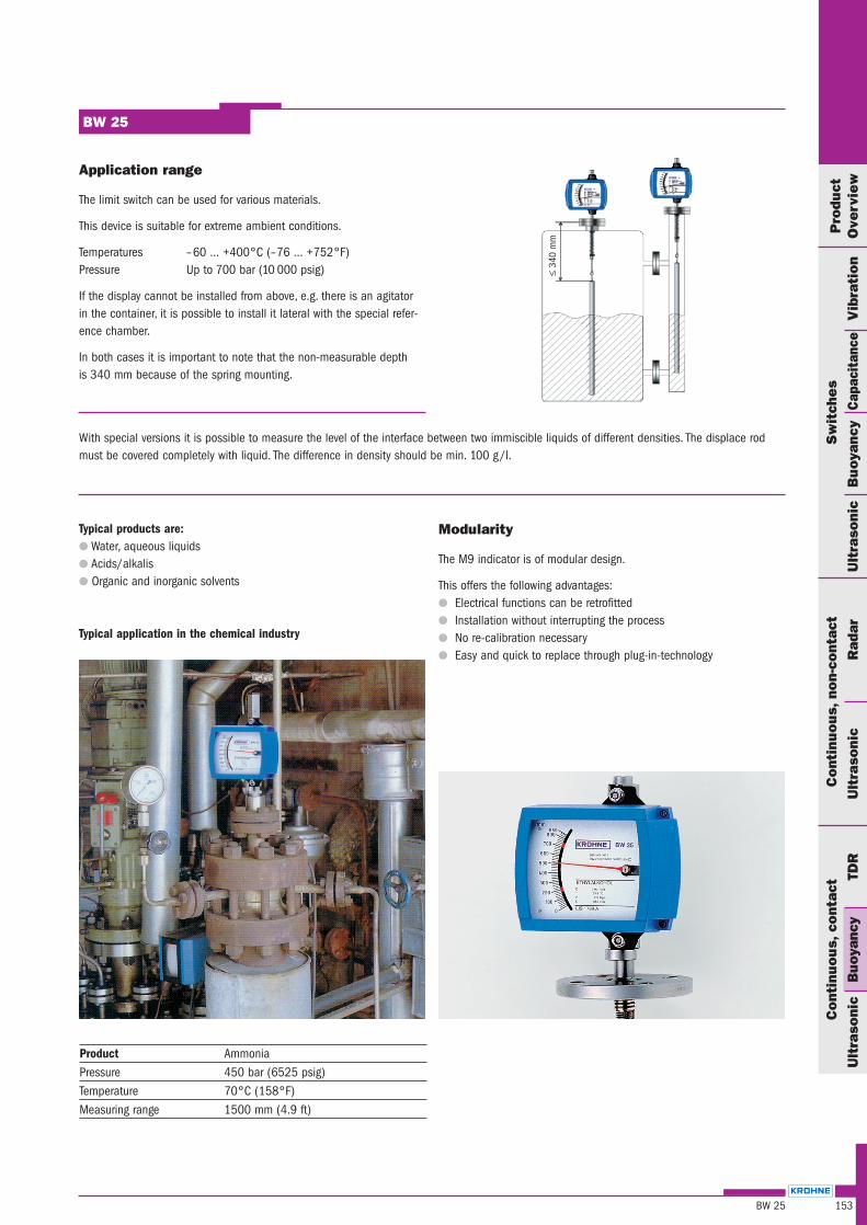
Application range
The limit switch can be used for various materials.
This device is suitable for extreme ambient conditions.
Temperatures –60 … +400°C (–76 … +752°F)Pressure Up to 700 bar (10 000 psig)
If the display cannot be installed from above, e.g. there is an agitatorin the container, it is possible to install it lateral with the special refer-ence chamber.
In both cases it is important to note that the non-measurable depthis 340 mm because of the spring mounting.
Modularity
The M9 indicator is of modular design.
This offers the following advantages: Electrical functions can be retrofitted Installation without interrupting the process No re-calibration necessary Easy and quick to replace through plug-in-technology
Product AmmoniaPressure 450 bar (6525 psig)Temperature 70°C (158°F)Measuring range 1500 mm (4.9 ft)
With special versions it is possible to measure the level of the interface between two immiscible liquids of different densities. The displace rodmust be covered completely with liquid. The difference in density should be min. 100 g/l.
≤34
0 m
m
Typical products are: Water, aqueous liquids Acids/alkalis Organic and inorganic solvents
Typical application in the chemical industry
Technical data
Operating conditionsProduct LiquidsDensity ≥ 0.45 kg/lMeasuring range 0.3 – 6 m (1 – 20 ft)Measuring accuracy ± 1.5 % of full scale rangeTemperature –60 … +400°C (–76 … +752°F)Ambient temperature ≤ 60°C (≤ 40°F)Operating pressure
Standard 40 bar (580 psig)Optional 700 bar (10 000 psig)
Indication Linear scale markingsmm, cm, m, inch, ft, %, volume
MaterialHousing Die-cast aluminiumDisplacement rod
Standard Stainless steel 1.4571 (316 Ti)Optional Titanium
SpringStandard Stainless steel 1.4571 (316 Ti)Optional (>100°C /212°F) ATS 340
Flange with pressure gland Stainless steel 1.4571 (316 Ti)ConnectionFlange DIN 2501 or ANSI 16.5
Standard DN 50, PN 40Optional DN 40/50/80/100, PN 40; DN 50, PN 64/100
11/2”/ 2’’/ 3’’/ 4”, 150/300 lbScrew G 11/2’’
Others on requestProtection category (EN 60529 / IEC 529) IP 65Electromagnetic compatibility (EMC) EN 50081-1, EN 50082-2
BW 25
154 BW 25
Responsibility for suitability and intended use of our instruments rests solely with the purchaser.
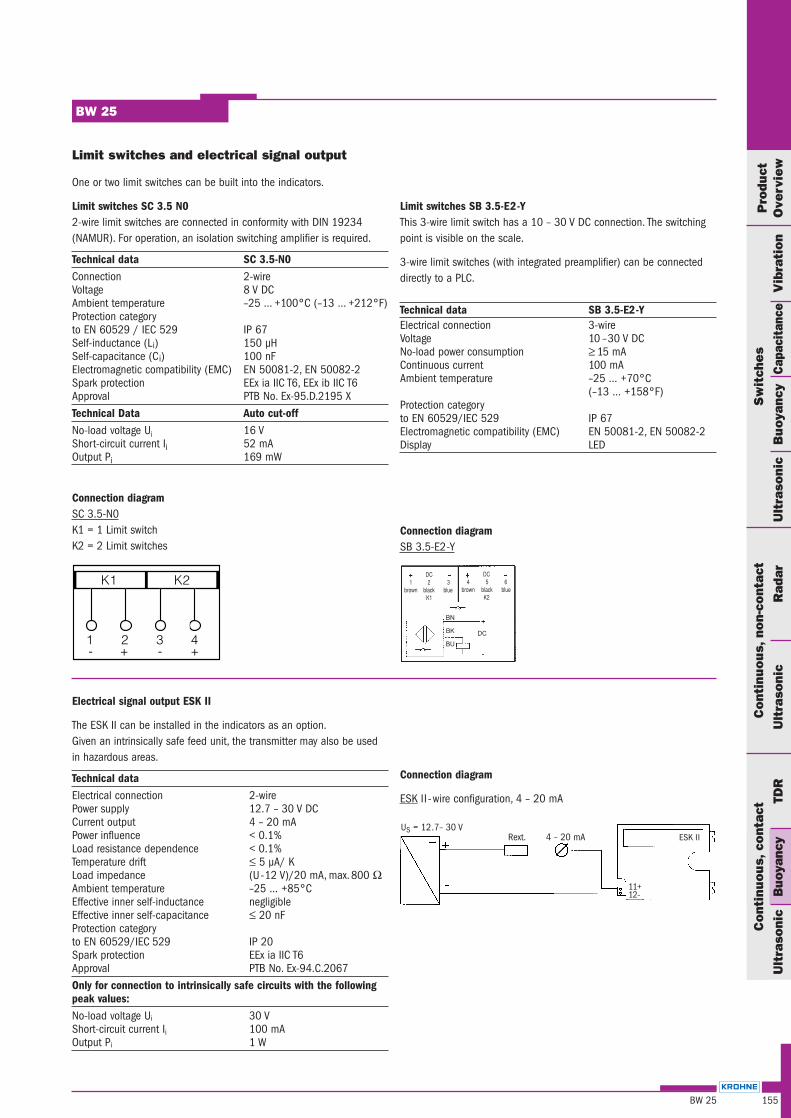
Limit switches and electrical signal output
One or two limit switches can be built into the indicators.
Limit switches SC 3.5 N02-wire limit switches are connected in conformity with DIN 19234(NAMUR). For operation, an isolation switching amplifier is required.
Technical data SC 3.5-N0Connection 2-wireVoltage 8 V DCAmbient temperature –25 … +100°C (–13 … +212°F)Protection categoryto EN 60529 / IEC 529 IP 67Self-inductance (Li) 150 µHSelf-capacitance (Ci) 100 nFElectromagnetic compatibility (EMC) EN 50081-2, EN 50082-2Spark protection EEx ia IIC T6, EEx ib IIC T6Approval PTB No. Ex-95.D.2195 XTechnical Data Auto cut-offNo-load voltage Ui 16 VShort-circuit current Ii 52 mAOutput Pi 169 mW
Connection diagramSC 3.5-N0K1 = 1 Limit switchK2 = 2 Limit switches
155BW 25
BW 25
Pro
duct
Ove
rvie
wU
ltra
soni
cB
uoy
ancy
Cap
acit
ance
Ult
raso
nic
Rad
arU
ltra
soni
cB
uoya
ncy
TDR
Cont
inuous,
non-
cont
act
Sw
itch
es
Vib
rati
on
Cont
inuous,
cont
act
K1K1
DC1 2 3
brown black blueK1
DC4 5 6
brown black blueK2
BN
BK
BU
DC
Connection diagram
ESK II -wire configuration, 4 – 20 mA
US = 12.7– 30 V4 – 20 mARext.
11+12–
ESK II
Limit switches SB 3.5-E2-YThis 3-wire limit switch has a 10 – 30 V DC connection. The switchingpoint is visible on the scale.
3-wire limit switches (with integrated preamplifier) can be connecteddirectly to a PLC.
Technical data SB 3.5-E2-YElectrical connection 3-wireVoltage 10 –30 V DCNo-load power consumption ≥ 15 mA Continuous current 100 mAAmbient temperature –25 … +70°C
(–13 … +158°F)Protection categoryto EN 60529/IEC 529 IP 67Electromagnetic compatibility (EMC) EN 50081-2, EN 50082-2Display LED
Connection diagramSB 3.5-E2-Y
Electrical signal output ESK II
The ESK II can be installed in the indicators as an option.Given an intrinsically safe feed unit, the transmitter may also be usedin hazardous areas.
Technical dataElectrical connection 2-wirePower supply 12.7 – 30 V DCCurrent output 4 – 20 mAPower influence < 0.1%Load resistance dependence < 0.1%Temperature drift ≤ 5 µA/ KLoad impedance (U-12 V)/20 mA, max.800 ΩAmbient temperature –25 … +85°CEffective inner self-inductance negligibleEffective inner self-capacitance ≤ 20 nFProtection categoryto EN 60529/IEC 529 IP 20Spark protection EEx ia IIC T6Approval PTB No. Ex-94.C.2067Only for connection to intrinsically safe circuits with the followingpeak values:No-load voltage Ui 30 VShort-circuit current Ii 100 mAOutput Pi 1 W
BW 25
156 BW 25
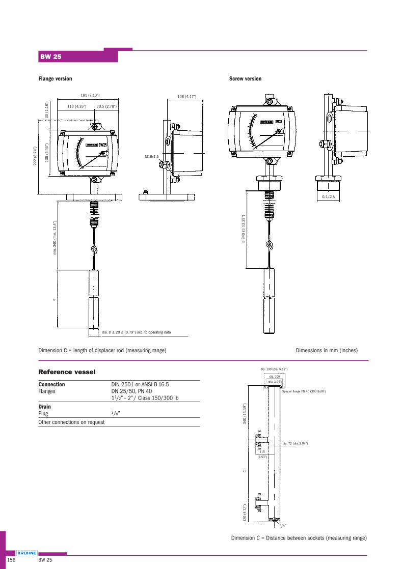
Reference vessel
Connection DIN 2501 or ANSI B 16.5Flanges DN 25/50, PN 40
11/2” – 2”/ Class 150/300 lbDrainPlug 3/8”Other connections on request
3/8”
dia. 130 (dia. 5.12”)
dia. 100
30 (
1.18
”)
181 (7.13”)
dia. D ≥ 20 ≥ (0.79”) acc. to operating data
Dimension C = length of displacer rod (measuring range) Dimensions in mm (inches)
Dimension C = Distance between sockets (measuring range)
Flange version Screw version
110 (4.35”) 70.5 (2.78”)
138
(5.4
3”)
222
(8.7
4”)
106 (4.17”)
M16x1.5
min
.340
(m
in.1
3.4”
)c
G 1/2 A
≥34
0 (≥
13.3
9”)
340
(13.
39”)
C12
0 (4
.72”
)
(dia. 3.94”)
Special flange PN 40 (300 lb/RF)
dia. 72 (dia. 2.84”)
115
(4.53”)
157BW 25
BW 25
Pro
duct
Ove
rvie
wU
ltra
soni
cB
uoy
ancy
Cap
acit
ance
Ult
raso
nic
Rad
arU
ltra
soni
cB
uoya
ncy
TDR
Cont
inuous,
non-
cont
act
Sw
itch
es
Vib
rati
on
Cont
inuous,
cont
act
Approvals
ApplicationWith explosion protection:In stationary storage tanks for flammable liquids ofdangerous materials classes AI, AII and B, excl.carbon disulphide (CS2), in Zone 0.Note: Certified devices are not standard versions! Deviations in design and technical data are possible!
Instrument version
BW 25 /... /. /.. /.. /.. – .. / Z0
Certification mark
PTB No. III B/S 1970
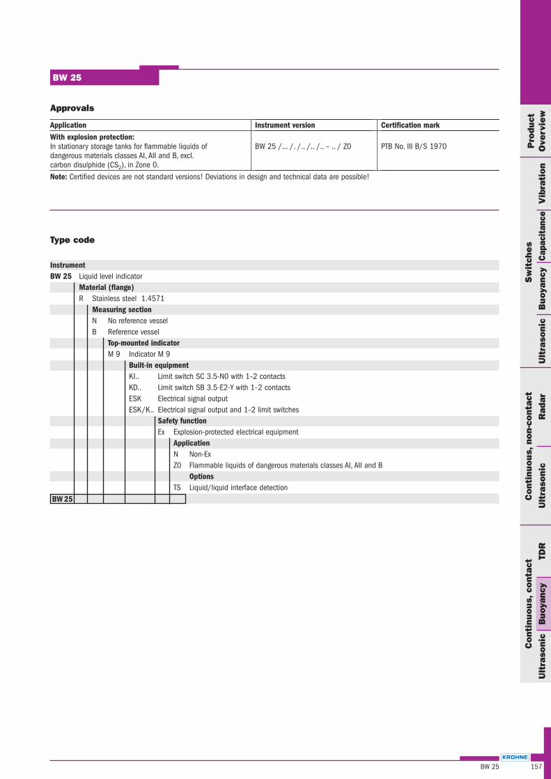
Type code
InstrumentBW 25 Liquid level indicator
Material (flange)R Stainless steel 1.4571
Measuring sectionN No reference vesselB Reference vessel
Top-mounted indicatorM 9 Indicator M 9
Built-in equipmentKI.. Limit switch SC 3.5-N0 with 1–2 contactsKD.. Limit switch SB 3.5-E2-Y with 1–2 contactsESK Electrical signal outputESK/K.. Electrical signal output and 1–2 limit switches
Safety functionEx Explosion-protected electrical equipment
ApplicationN Non-ExZ0 Flammable liquids of dangerous materials classes AI, AII and B
OptionsTS Liquid/liquid interface detection
BW 25

Notes