Embed Size (px)
DESCRIPTION
Grouting Equ
Citation preview

EQUIPMENTCHAPTER 6
EM 1110-2-350620 Jan 84
6-1. Introduction. Guidance for selecting or approving the specializedequipment necessary for a grouting project is provided below, and operationalprinciples for the equipment are outlined and related to job requirements.Additional guidance for selection of drilling methods is contained inparagraph 4-4.
6-2. Drilling and Grouting Equipment.
a. Drill Rigs. In the selection of a drill, site considerations and jobdrilling/grouting requirements dictate the type and size of drill to be used.Drilling from the surface may require either a crawler, wheel, or skid mountedunit. On steep abutments a post drill which attaches to the grout nipple maybe the only feasible choice, and may be suitable for other drilling. A multi-purpose drill embodying auger, rotary, and rock coring capabilities is de-sirable (fig. 6-l). The size of drill is dependent on the depth and size ofholes and the type of formation drilled. Additional requirements may includestable outrigging and a highly visible and centralized control panel. Drill-ing from within an adit, tunnel, shaft, gallery, or buried structure usuallyrequires small, lightweight, and compact type drills (fig. 6-2 and 6-3). Fastrod coupling, 360-degree angle drilling, self towing, and multiple power op-tions are ❑ajor considerations for subsurface drills. Comparisons betweendrilling methods and equipment are discussed in paragraph 4-4.
b. Percussion Drilling. Percussion drills are operated by air- orhydraulic-driven hammers. The best known types are-the jackhammer, thedrifter, and the wagon drill. The drill proper consists of a hollow steel rod,which is fitted with a fixed or detachable bit on one end and a shank on theother.
(1) Operation. Percussion drills are used for drilling in rock. Thepercussion drill does not reciprocate. The shank fits loosely into the chuckat the forward end of the machine, where it is struck by a hammerlike pistonactuated by compressed air or hydraulic fluid. The air compressor capacitynecessary to operate a single-hammer drill ranges from 50 to 200 cubic feetper minute, depending upon the size of the drill cylinder and the pressure atwhich air is supplied. The bit remains in close contact with the rock at thebottom of the hole at all times during drilling except during the slight re-bound caused by impact of the hammer. Drills are provided with a mechanismthat causes the drill steel rod to rotate between blows of the hammer. cut-tings or sludge materials are removed from the hole by air or water thatpasses through the machine and down the hollow steel drill rod to the bottomof the hole, and then rises up the hole to the surface. Removal of cuttingsby water is sometimes preferred for grout hole drilling but is not mandatoryin all cases. In some instances, it may be desirable to remove cuttings by
6-1

EM 1110-2-3506
20 Jan 84
/’
-.
%
-.
Figure 6-1. T~ical truck-mounted drill rig (permission by Mobile
Drilling Company)
6-2

Figure 6-2. Electric over hydraulic drill rigs for
6-3
gallery grouting!,3—’

EM 1110-2-350620 Jan 84
*
Figure 6-3. Post drill
air. Jackhammer drills are only suitable for shallow work, and due to theirlight weight, are usually held in position by hand. Drifter-type drills aredesigned for tripod, bar mounts, or jumbos. The commercially available wagondrill is composed of a drill head mounted in leads that are supported on atrack, wheel-, or skid-mounted chassis (fig. 6-4).
(2) Application. Generally, percussion drilling produces acceptablegrout holes and is the most economical.method of drilling shallow holes. Thisadvantage decreases with depth. The edges or wings of the bit wear away dur-ing the drilling operation, and a progressively smaller hole is drilled.
6-4

EM 1110-2-350620 Jan 84
Figure 6-4. Air Trac drill
Therefore, contract specifications should state the minimum acceptable size ofgrout hole whenever size is a pertinent factor, and provide the method forchecking hole size.
(3) Down-hole hammer. Air activated bottom-hole-hammers are used inmost types of rock strata. These hammers can be used on most drills that canbe slowly rotated and have slow and closely controlled down-hole feed. Thehammer air exhaust is released at the bottom of the hole. Cuttings are blownfrom the hole by exhaust air which cools the bit. The hammer is a versatiletool for the drilling of rock sockets and blast holes in hard rock (fig. 6-5).
c. Rotary Drilling. Rotary drilling is the process of making a hole byadvancing a drilling bit attached to a rotating column of hollow drill pipe.The drill pipe is turned by a motor at speeds ranging from approximately200-300 to 3,000 rpm or more. Pressure on the bit is applied hydraulically or
6-5

EM 1110-2-350620 Jan 84
PREPMATIONFOR DRILLINGPRINCIPLES OF OPERATION
The piston is the only moving padduring operation of the Megadril@,(See Figure 1) The piston’s up-and-down strokes are controlledby the flow of high-pressure airthrough the case,
With bit in extended position(tool off bottom)
The Megadril@ is designed topass full air volume when off bot-tom, without operating the piston,in order to blow water from the holeor to accelerate periodic cleaningof the hole.
Figure 6-5. Down-hole hammer
6-6

EM 1110-2-350620 Jan 84
mechanically. Water is forced through the drill pipe to wash cuttings out ofthe hole. Drill rigs vary in size from small, lightweight machines capable ofdrilling holes only a few hundred feet deep to large rigs that can drill holesmiles in depth. The small rigs are usually satisfactory for grouthole drill-ing and are desirable from the standpoint of portability. Drill bits adapt-able to a great variety of subsurface conditions are available. Some of thecommon types are shown in figure 6-6 and are discussed as follows:
(1) Diamond bits. Diamond bits may be either a core or a plug type.Both types employ a diamond-studded bit to cut the rock. The bit is cooledand the hole is continuously cleaned by water or compressed air pumped throughthe drill rods.
(a) Core type. The core-type bit consists of a hollow steel cylinder,the end of which is studded with diamonds. The bit is fitted to the lower endof a hollow steel chamber (core barrel) that is rotated rapidly while the bitis held firmly against the rock so that the diamonds cut an annular channel inthe rock. The rock that lies within the channel and projects into the barrelconstitutes the core.
(b) Plug type. Two varieties of plug bits are available commercially.One is a concave type, the head of which is depressed toward the center; andthe other is a pilot type and has a protruding cylindrical element that issmaller in diameter than the ❑ain bit head. Noncoring diamond bits have awide field of usefulness in foundation grouting. However, plug bits are morecostly than coring bits for drilling in extremely hard foundations and inbadly fractured rock because of greater diamond cost. Since plug bits produceonly cuttings, more diamonds are required to make a given footage of hole thanif a large part of the rock encountered is removed as core. The loss of oneor two diamonds from the center of a noncoring bit occasionally occurs whenshattered rock is drilled and renders the bit useless for further cutting.Except where wire line is used, the plug bit may be less expensive to use thanthe core bit in deep holes due to the time saved by not having to pull out ofthe hole to empty the core barrel or to clean a blocked bit. A commerciallyavailable bit utilizing polycrystalline diamond blanks has proven very ef-fective. Penetration rates reportedly two and three times greater than tung-sten carbide and surface set diamond drill bits, respectively, have beenobtained.
(c) Size. The sizes of diamond bits are standard and are generally shownby the code letters EW, AW, BW, NW. The dimensions of each size are presentedin the tabulation that follows. Most diamond-drilled grout hole sizes are EWor AW.
6-7

1
W 1110-2-350620 Jan 84-
LOHE -~PE . - . PUJG TYPE
DIAMOW BITS.,. ..
@,..@”g..~-., ..... ....ROCK BITS
FISHTAILBIT
DRAG #lTS
Figure 6-6. Drill bits
Size, inches Size, mCode Hole Core Hole Core—. ——EW 1-31/64 27/32 37.7 21.5AW 1-57/64 1-3/16 48.0 30.1BW 2-23/64 1-21/32 60.0 42.0Nw 2-63/64 2-5/32 75.7 54.7
Wire line bits listed below,~eld the same size hole but not the same sizecore as the bit shown above.
Size, inches Size, lmICode Hole Core Hole Core— — ——
AQ 1-57/64 1-1/16 48.0 27.0BQ 2-23/64 1-7/16 60.0 36.5NQ 2-63/64 1-7/8 75.7 47.6
(2) Hard ❑etal bits. Drill bits of hardened steel notched to resemblethe teeth of a saw can be placed on the core barrel to substitute for a morecostly diamond bit. In some soft rocks this type of bit makes a hole muchfaster, is not as easily blocked, and is much cheaper than a diamond bit. Theteeth of such bits are often faced with one of the alloys of tungsten carbide,or replaceable inserts of a hard alloy are welded into holes cut into the bitblank. The hard alloys can also be used to make a noncoring bit.
6-8

EM 1110-2-350620 Jan 84
(3) Roller rock bits. Rock bits,bottom of a hollow drill pipe column.
like diamond bits, are attached to theThe bit is made of toothed rollers or
cones, and each turns or rolls on the rock as the bit rotates with the drillpipe. Cutting is accomplished by crushing and chipping operations. The shape,attitude, and number of teeth and the number of rollers vary. Most bits havethree or four cones or rollers; some have two. The teeth and other parts ofthe bits subjected to intense abrasion are made of hard alloys. Cuttings andsludge are washed out of the hole by circulating water or drilling mud throughthe drill pipe and back to the surface between the drill pipe and the walls ofthe hole. The roller rock bit is not extensively used for grouthole drillingbecause the smallest available size is approximately the same as that of anNW-diamond bit.
(4) Drag and fishtail bits. The drag bit is a general service bit forrotary drilling. The bit is capable of drilling soft rock and most soils andis used extensively in foundation explorations and grouthole drilling. Thefishtail bit is so named because of its resemblance to a fish tail. The di-vided ends of the single-blade bit are curved away from the direction of rota-tion. Other drag bits have three or four bladesplaceable.
, which may or may not be re-The cutters or cutting edges of the blades are ❑ade of hardened
steel or are covered with hard alloys. Almost any desired size is available.
(5) Summary. Drill bit types and the materials in which they are gen-erally used are as follows:
Drill Bit Type
DiamondCore
Plug
Hard metal
Rock
Drag and fishtail
Percussion
Principal Use
Rock and concrete
Rock
Soft rock, hard clay,and cemented soils
Rock
Soft rock and soil
Rock and concrete
Not Suited for
Unconsolidated soils
Extremely hard rock,extremely soft rock,unconsolidatedsoils, and shatteredor fractured rock
Hard rock and uncon-solidated soils
Unconsolidated soilsand very hard rock
Hard rock
Unconsolidated soils
e. Auger Drills. The auger drilling rig powers either short, spiral-shaped tool; or drill rods wit~ continuou= heii~al fluting. The spiral-shapedtool is run on a torque bar and serves as a platform to remove cuttings. Thedrill rod acts as a screw conveyor to remove cuttings produced by an
6-9
EM 1110-2-350620 Jan 84
auger-drill head, and is also referred to as a continuous-flight auger. Theauger bits are made of hard steel or tungsten-carbide-tipped cutting teeth.The larger diameter continuous-flight augers are available with a hollow tube/stem through which grout can be placed. Auger drilling is conducted in soilsand very soft rocks to depths rarely exceeding 100 feet.
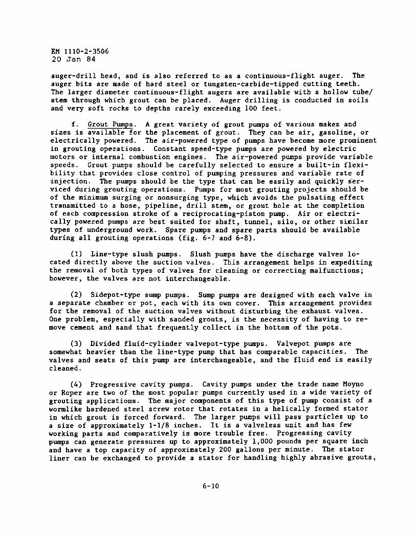
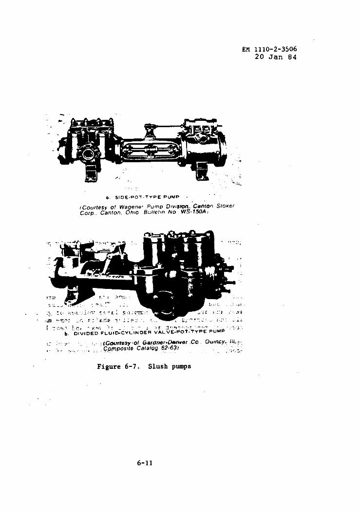
f. Grout Pumps. A great variety of grout pumps of various makes andsizes is available for the placement of grout. They can be air, gasoline, orelectrically powered. The air-powered type of pumps have become more prominentin grouting operations. Constant speed-type pumps are powered by electricmotors or internal combustion engines. The air-powered pumps provide variablespeeds. Grout pumps should be carefully selected to ensure a built-in flexi-bility that provides close control of pumping pressures and variable rate ofinjection. The pumps should be the type that can be easily and quickly ser-viced during grouting operations. Pumps for most grouting projects should beof the minimum surging or nonsurging type, which avoids the pulsating effecttransmitted to a hose, pipeline, drill stem, or grout hole at the completionof each compression stroke of a reciprocating-piston pump. Air or electri-cally powered pumps are best suited for shaft, tumel, silo, or other similartypes of underground work. Spare pumps and spare parts should be availableduring all grouting operations (fig. 6-7 and 6-8).
(1) Line-type slush pumps. Slush pumps have the discharge valves lo-cated directly above the suction valves. This arrangement helps in expeditingthe removal of both types of valves for cleaning or correcting malfunctions;however, the valves are not interchangeable.
(2) Sidepot-type sump pumps. Sump pumps are designed with each valve ina separate chamber or pot, each with its own cover. This arrangement providesfor the removal of the suction valves without disturbing the exhaust valves.One problem, especially with sanded grouts, is the necessity of having to re-move cement and sand that frequently collect in the bottom of the pots.
(3) Divided fluid-cylinder valvepot-type pumps. Valvepot pumps aresomewhat heavier than the line-type pup that has comparable capacities. Thevalves and seats of this pump are interchangeable, and the fluid end is easilycleaned.
(4) Progressive cavity pumps. Cavity pumps under the trade name Moynoor Roper are two of the most popular pumps currently used in a wide variety ofgrouting applications. The major components of this type of pump consist of awormlike hardened steel screw rotor that rotates in a helically formed statorin which grout is forced forward. The larger pumps will pass particles up toa size of approximately 1-1/8 inches. It is a valveless unit and has fewworking parts and comparatively is more trouble free. Progressing cavity
Pws can generate pressures up to approximately 1,000 pounds per square inchand have a top capacity of approximately 200 gallons per minute. The statorliner can be exchanged to provide a stator for handling highly abrasive grouts,
6-10
Efl1110-2-350620 Jan 84
*. .
..
.
. .
0. SIDE-POT-TYPE PuMP .“
,
fCourfesyofWagenefPump Dfv/sion,.CantonSroKerCorp.c~n!on.onto Buliet,nNO W~-lMA )
Figure 6-7. Slush pUllkpS
6-11

~ 1110-2-350620 Jan 84
Figure 6-8. Cutaway section of progressive cavity pump
chemical grouts, and petroleum products. These pumps are free of pulsationand can be used to pump a great range of grout consistencies. The largerPqs are sometimes used to pump sanded ~routs containing steel fibers. Theopen-throat types are the best suited for handling grouts containing fillers.
(5) Centrifugal pumps. Centrifugal pumps are sometimes used to pumphighly fluid sanded and unsanded cement grout. These pumps come in a varietyof sizes and makes and ard capable of pumping large volumes of grout at lowpressures. Seals and bearings for the impeller shafts of some ❑akes of thesepumps require frequent replacement as a result of wear and tear by abrasion.
g“ Concrete Pumps. Concrete pumps are occasionally used to pump sandedand unsanded cement grouts in cases where the consistencies of such mixturesrange from moderate to near minimum fluidity. The latter mixture is often de-scribed as being stiff or having a standard slump cone consistency ranging be-tween 4 and 8 inches. These pumps can easily handle aggregate to a maximumsize of 1 inch and are also capable of pumping grouts containing steel fibers.These units are composed of reciprocating pistons housed at the bottom of astowing type hopper. The piston delivers the grout directly into 4-inch orlarger steel pipelines through a swedged head-type coupling. The pum’Psarenormally either truck or trailer mounted and gasoline powered. They are notused in grouting applications that require close pressure controls but aremainly used in filling large cavities, and at times are used to deliver groutto tremies when such cavities are filled with water.
6-12

h.mixer is
EM 1110-2-350620 Jan 84
Grout Mixers. The first consideration in the selection of a groutto ensure that it has the desired capacity and will produce a homo-
geneous mixture in a desired period of time.
(1) Tub mixers (fig. 6-9). Tub mixers of various capacities and arrange-
ments of mixing blades are the most common type used. They are usually air
powered, and the grout is mixed by several horizontal blades mounted on a ver-
tical spindle. These mixers are used individually but more often than not con-sist of two or more tubs that are either parallel or in a series.
The paddle
blades are arranged in pitch to force grout to the lower section of the tubwhere the grout is discharged through either a quick-opening syrup/petroleum
Figure 6-9. Two tub-type grout ❑ixers and open throat progressingcavity pump
6-13

EM 1110-2-350620 Jan 84
or similar type valve into a sump. These types of mixers are seldom designedto mix more than 1/2 cubic yard of grout. Four- to fifteen-cubic-foot-capacity tubs are the most convenient sizes for use in most grout applica-tions. Outstanding features of tub mixers are that they can be easilycharged, observed, and cleaned.
(2) Horizontal drum mixers, ribbon and paddle types (fig. 6-10 and6-11). Grouting jobs that require moderate to large quantities of grout fre-quently utilize a horizontally positioned drum having length-to-diameterratios that range from approximately 2:1 to 4:1 and are capable of mixing ap-proximately 8 cubic yards of grout. The drum is placed in a fixed horizontalposition with a drive shaft centered along its long axis that is supported bybearing blocks enclosed in steel hubs. Affixed to the shaft are a series ofpaddles placed at selected intervals and normal to the shaft, or the drum maycontain a series of metal segmented or continuous spiraling strips that arepositioned near the inside perimeter of the drum and supported from the shaftby a series of struts. These mixers have a charging chute at the top of oneend and a discharge valve at the bottom near the other end. They are usuallyair-powered; however, some are driven from truck-powered takeoff shafts.
(3) High-speed colloidal mixers. Colloidal mixers (fig. 6-12) are com-mercially available in both the single- and double-drum types. These unitsutilize centrifugal pumps that circulate highly fluid grout mixtures at highspeeds through the drum system during mixing. These mixers are superior tostandard slow speed mechanical mixers in that they produce grout of greateruniformity with better penetrability and pumpability. Cement clusters areseparated and the individual particles are often broken and rounded to a sig-nificant degree making it possible to grout tighter fractures. Colloidalmixers should be required for mixing and hydrating bentonite. Bentonite shouldbe mixed in a separate mixer and fully hydrated before being introduced intothe grout mixer. The bentonite mixer must not be contaminated with cement be-cause it would reduce the swell properties and, thus, the grout stabilizingability of the bentonite. Hydration of bentonite can be accomplished in lessthan 1 ❑inute in a colloidal mixer as compared to approximately 24 hours in aslow speed mixer.
(4) Transit mix and skip-loaded concrete mixers. Transit and skip-loaded mixers are sometimes used as grout mixers; however, mixer efficiency issacrificed as a result of the lack of shearing action being imparted to themixture because of slow revolution-per-minute rates. When such mixers areused for grout, the problem can be somewhat minimized by mixing grout volumesthat do not exceed one half of the rated capacity of the mixer drums. Onemajor benefit of these mixers is the large quantity of grout that can be mixedsince some units have mixing capacities of 12 cubic yards.
(5) Jet mixing units. Jet mixers generally produce less mixing effi-ciency than most mixing systems. These units consist of a large metal funnelmounted atop and in line with a metal water line. The dry bulk cement or dry
6-14

PLATE STEEL
T,
?4G
,+4 “ 4s.
‘.~-, wELOED ALL AROUND
b:,,,, GREAsE FITTING
‘.:’.:,~PACKl NGA ,.. OUTsl DE
BRONZE EuSHING-~,,. .‘.IIF
! ! 1 I 1’1 y,,,,, ~L&TEL !)4- PLATE-W ‘..--6 -.&.- -- 1’2. -- -..*.-. -- 12. .- . ..&.. –. ,2... -.&~.,,2,,.
P. . . . . . . . . . . . . . . .- . . ..- - 49-(12” ------ ------– -------- --- -
1 I )1. A b b -BOLTED NEAO
‘.~/2cLEARANc E ~. , ‘-WELDED ALL AROUND., ./’
I 3,- PIPE NIPPLE y.,- ,.
‘-.114” n !-1/2,, PLATE S-----(TUREAOEDI
-3/ 16,, PLATE
MOTOR END DETAIL WELDED TO PA ODLES
0-!12,, x 0.
i* ‘.6-q X tl~ PLATE
‘-DIRECTION OF TWIST ST AGGEREO~ IN EACH SET O!= PA ODLES
.1/2, x l/4,, pLATE.‘.-CUT OUT ON FIRST TWO SETS
SLOT PA ODLES ‘-’ NEAREST WATER INLET
LONGITUDINAL SECTION
NOTE 100- WELDING UNLESS BOLTED
CONNECTION IS SHOWN
PADOLE DETAIL
Figure 6-10. Horizontal drum grout mixer, 8-cubic-foot capacity

“ !/4. L ;
\
. . . . . . .. ,
/
~ ~. ~. -3!4.Roos 2,.5.WELDEO.. .Z . . . .
\S/4- ROO, j
TWO 1-1/2. PIP12MfippLEs FOR. ~
0m
GREASE FIT TIN G-. j“ , 16-.:. 112.1+112.
-,!. II ‘~ELLYEO TO TIPS Oi ❑ ,AD,. i & - /&
‘..MIxEROAISREL,. : e..S18. ST EEL-. ““ — .— –_Q P“-t14. 5TEEL PLATE---.4 z- ‘ ‘h , :.g, ::
PLATC& s.. -1/2. SrCCL pLATE
o fu a.S. PIPI! SKIDS I$TC12L)— —-—.—— ————
: i,, .
4,.s. .
- /-{
‘::5. FLANGE6. STRAIGISTWAV
SECTION LUORICATEO PLUG
VALVE END ELEVATION,, LIGHT WEIGHT
STEEL PIPE..<’i 1’.— 1
STAGGER OIREC-
+
TION 0? TWISTIM CACN SETOF .BLADES ARC
PAOOLCS .. . . . .. ..“814. MC. .16.
STEEL PLATE
WRACES,. ( 1/4. PLATE
e:-:.. )): .=____ ‘;.
. 6...
MOTORSUPPORT2 REQUIREDPLAN SHEAR PIN
TAP FOR 3/e. s S/6... SET SCREW
:..:< ).t/2.
60”
....
I’ iii f
MlxER BLAOES2 REQuIRED AS SHOWN
2 RmUIREO~lT E H~ND
SECTION COLLARSTUB SHAFT
STUB SHAFT ASSEMBLYANO PARTS
(Courtesy of U. S. Bureeu of Reclamation) ●
Figure 6-11. Horizontal drum grout mixer, 27-cubic-foot capacity

EM 1110-2-350620 Jan 84
,.
This larger version of the CG-600 is 68” wide, 102” long, and has 17 cubic feetmixing and holding tanks. Output ranges up to 20 gpm depending upon themix. The standard discharge pump has a pressure of 225 psi and is capable ofpumping sanded mixes. Higher pressure pumps (up to 1500 psi) are alsoavailable. Controls are centrally grouped for ease of operation. All drives aremechanical to minimke costly, unnecessary downtime. Cleanup is less than10 minutee/shift.
CG=650/
Type Power Quantity1
Air 100psi 370cfm
Electric 2301460 W27 amps
Gasoline Available
Diesel AvailableF
Figure 6-12. Colloidal mixer
6-17

EM 1110-2-350620Jan 84
bulk blended grout materials are continuously metered into the fumel by meansof a flapper valve. A forced stream of mixture water is continuously meteredby pipe just below the orifice of the funnel which causes shearing and tur-bulent mixing action. The resulting mixture is jetted into a holding tank, ismeasured for designed weight and fluidity, and, if needed, is adjusted for cor-rections to cement and water metering. When the mixture is properly adjusted,the suction side of large pumps picks up and transfers the grout to a dis-charge pump. Large volumes of grout can rapidly be placed using this method.This unit 1s some~imes used to place quick-~ett~ng mixtures;ing tanks are in the system. A sampling “T” for providing ais in line.
(6) Compressed-air tank ❑ixers. Compressed-air mixers
ho<ever, no hold-degree of control
are occasionallyused for accu~ate batching and mixing. Th~se types of mixers may range in c~-pacity from a few cubic feet to 500 cubic feet. Dry ❑aterials are fed to thetank through a pipe comection located at the tank side below the water level.Air and mixing water provided through vertical connections discharge into theinterior of the tank. The air-mixed grout is discharged from a connection lo-cated at the base of the mixing cone.
i. Agitator Holding Tanks. To provide a high volume and continuous in-jection of grout, two mixers are usually set up to alternately discharge intoan agitator holding tank that has a capacity at least two and preferably up tothree times the capacity of the mixil~gsystem. Tub or horizontal type mixersoperated at slow speeds are frequently used for agitating holding tanks. Agi-tator holding tanks can be similar in design to the tub-type mixers shown infigure 6-9. Volumes of grout used from the agitator holding tanks can be mea-sured by marks at different levels in the tanks.
j. Grout Lines. Two primary arrangements of grout piping are used tosupply grout from the pump to the hole. The simpler of the two, the single-line system, is used in a variety of grout placements. The system consists ofa pipe or a hose or 5 combination of both extending from the pump discharge tothe header at the hole collar. The pump speed controls the rate of grout in-jection. The second arrangement, which provides a circulating system, is com-posed of a double line, and one of the lines serves as a return line from theheader to the grout pump, sump, or holding tank. This line provides for thecontinuous circulation of the grout through the single line and pump. Thedouble-line system can also be used to meter a desired amount of grout down-hole by simply varying the openings of a valve on the return line withoutchanging pump speed. Pressure is controlled by one or more valves on the con-trol line. A circulating grout header should normally be required for founda-tion grouting.
(1) Hose lines most commonly used for discharge and suction are theflexible type, usually made of reinforced rubber or plastic. The inside diam-eter of these hoses for mostThe larger the diameter of a
grouting applications ranges from 1 to 2 inches.given type of hose, the less the working pressure.
6-18

EM 1110-2-350620 Jan 84
Hoses should be selected that have working pressures at known temperaturesthat will withstand the maximum pressures anticipated with an ample margin ofsafety. Damaged hoses should be discarded.
(2) Pipelines of black steel are sometimes used in long runs from thepump to an array of holes to be grouted. The lines should be at least one halfagain the diameter of the flexible lines and should not contain any sharpbends or constrictions.
k. Headers. Headers permit grout injection through downhole lines aswell as provide continuous circulation at the surface. Headers may also per-mit grout injection through downhole lines and return up the annular space be-tween tubing and hole. See figures 6-13 and 6-14.
1. Valves. Valves for grout lines and header systems should be thequick-opening type, easily regulated, and resistant to corrosion and abrasion.They should be capable of accurately controlling pressures in all positions.When in the full open positionflow of grout.
, valves should not present a restriction to theDiaphragm-type valves have proven to be effective. Pressure
relief valves should be installed in grout lines as an added precaution.
m. Packers. Packers are often required in pressure grouting to confinethe injection of grout to certain foundation zones, to isolate a lost circula-tion zone, to separate grout stages, to grout sections of slotted or perforated
PRESSIJRE GAGE
DIAPHRAGM GAGE pLUG VALVEPROTECTOR
HAND COUPLING UNION
SAME HEADER TOBE
3
pLUG VALVEUSED FOR PACKERGROUTING BY PLACING
%
)!A BUSHING IN UNION
U
NOTE: ALL PIPE AND FITTINGS ARE l-1/?SIZE. PLUG VALVESTOBEUSEDTMROUGHOUT FOR PRESSURES ABOVEZSO PSI. GROUTHOSETOBE I-lIPWITH SCREW-TYPE COUPLINGS.
(CourtesyofAmericanSociety of Civil Engineers)
Figure 6-13. Direct grouting header
6-19

EM 1110-2-350620 Jan W
Figure 6-14. Circuit grouting header (not to scale)
casing, and to make surface comections. The three most commonly used packersare shown in figures 6-15 through 6-17.
(1) Cup leather removable packer. The cup leather removable packer isbest suited for use in holes drilled in moderately hard to hard rock and wherethe walls of the holes are relatively smooth and of the proper dimensions.This packer is attached to a single pipe for placement downhole. When properlyassembled and positioned, the packer can withstand pressures approaching1,000 pounds per square inch.
(2) Mechanical packer. This packer is an expandable type. It is diffi-cult to properly seat if the hole is rough or oversized and easily bypassed infractured rock. When properly assembled, expanded, and seated in good rock,the mechanical packer can also withstand pressures of approximately1,000 pounds per square inch. This type of packer is widely used in rockformations that vary from soft to hard.
(3) Pneumatic packer. The pneumatic or air packer can be used in
6-20

sTEEL COLLAR (SEE OETAIL)
7/9. ENo NUT, f REou!RED (sEE oETAIL)~ta~ 10 x 1.12s 00 x 1/8” BRASSWASHERo1 REQulREo
1-1/2” HARD LEATHER CUP. WELO 10 1/2” plpE4 REQUIREO: 27!S2” CuTou7
THREAD plpE 7/0”. 14 ‘F2’ 1“ ‘EPTH3/4- COUPLING
,/2’I ST ANOARo PIPE S/49 GROUT LINE10 MANIFOLD
________===-- , ---.----—----- ------------- ..— — -
!! .-----..— —. t ------------__ . ---—-----
--~~a-’”o
●
PACKER ASSEMBLY
DETAIL OF PACKER SPACER
1.0s001AM,S149 PIPE THREAD
o
::
66
DETAIL OF COLLAR
DETAIL OF END NUT
MAKE FROM STANDARD 7/8” HEXAGONAL NuT
(Courtesy 0/ U. S. Bureau of Reclamation)
Figure 6-15. Removable grout packer

EM 1110-2-3506Z()J~g ~
ADJUSTING NUT—
~A~H’~~
DRILL HOLE
\
\1-s/16” WASHER. LOWER SIDE
CONCAVE TO HOLD HOSE IN
)4
I
PLACE
1-s/16” WASHER, UPPER SIDE) I
~ STRAIGHT THREADS FOR e“
F SIZE ‘X GROUT HOLE
>
_ 1“ STANDARD PIPE
DEEPER THAN 20’,
JOINT CASING
- FOR HOLES
USE FLUSH
~ 1/2” STANDARD PIP’
CONCAVE TO HOLD HOSE INPLACE J
3
.
● WELD
i 1< ‘00s’ FIT ON 1/2” PIPE
4“ TO 6“ PIECE SOFT III~RUB13ER HOSE
(Courtesy of U. S. Bureau of Reclamation)
Figure 6-16. Mechanical packer
6-22

EM 1110-2-350620Jan ~
ASSEMBLY
TAPE 3/ Sl- AIR SUPPLY
LINE TO PACKER PIPE ‘---- ~~,
t/2- sTANDARD PlpE. ..----.:;~.;~
[“my,~‘ k
CONNECTION-COPPER !1TuBE TO RuBBER TuBE ----.7.;,. ~
ii~~114- COPPER TuBE EM-EEDDEO IN SLOT IN SHELL
.k~ )OF 1/2- PIPE AND BRA ZED...
!: I ~ !4”””-
SECTION ALONG C
9P.-COMPRESSEO AIR BOTTLE; WITH REGULATOR
m
k“1 ;..3/8. AIR
r
-SUPPLY LINE
....SUPPLY HOSE-y .-RETURN LINE
PRESSURE ‘-@ 1: ;. “ALVE5GAGE ~d:..,
---PAC.ER C’-’”p
r:——-——,~
;b .
t: :;:,’;/
\
T S7ANOAR0 PIPE ‘-- ..:- , . ; ,coNcRETEEMOEOOEO INFOOTING
‘; j~’f”:f” ‘~FJGwALL
,7, ‘,-. ,.
>60, ”‘- ‘+
.,’. ~t1-3/8q MINIMUM”” ‘::OIAM HOLE f;,
,.
I
TYPICAL VIEW OF LAYOUT
CROSS SECTION OF AIR-PACKERRuBBER TUBE
LOW MODULUS OF ELASTICITY ANO
HIGH TENSILE STRENGTH
NOTE: LENGTH OF AIR-PACKER RUBBERTUOE vARIABLE.
GROUT SUPPLY LINE-3f4” RUEBERHOSE UP TO 60- DEPTH, AND 31*”PIPE FOR GREATER DEPTH liOLE.
OIAMETER OF PACKER ANO CON-NECTIONS TO ❑ E LESS THAN MI Nl-SSUM OIAMETER OF HOLE.
(Courtesy of
Figure 6-17. Air packer
U. S. Bureau of Reclamation)
6-23

EM 1110-2-350620 Jar)84
oversized holes because of its expansivity. As an example, an EM size may beseated in 3- or 4-inch-diameter hole or casing, providing that the hole condi-tion is good. The packer is well suited for use in soft, fractured, and thin-bedded rocks. Grout injection pressure should be less than packer inflationpressure to prevent bypass of the grout.
n. Centralizers. Centralizers are sometimes required to position casingor injection pipe in the center of holes, particularly when casing or pipe isto be a part of a permanent subsurface type of installation. Assembled leafsprings with limit rings serve as centralizers and provide a uniform annulusaround the casing or the pipe, which can then be properly filled with grout.The centralizers aid casing and pipe to negotiate irregularities and doglegs.Commercially available centralizers are fabricated with hinges to facilitatetheir attachment to casing or pipe strings (fig. 6-18).
Figure 6-18. Centralizers,Courtesy Halliburton, Inc.
o. Tube Wiping/Displacement Plugs. Tube plugs are used in special grout-ing applications for displacement of a measured amount of grout down a hole.A hard rubber plug with a series of rubber discs is forced down the inside ofa steel tube by a fluid head acting on a steel ball seated atop the plug. Theball and plug are discharged into grout or retained in a plug catcher attachedto the bottom of the drill tubing.,
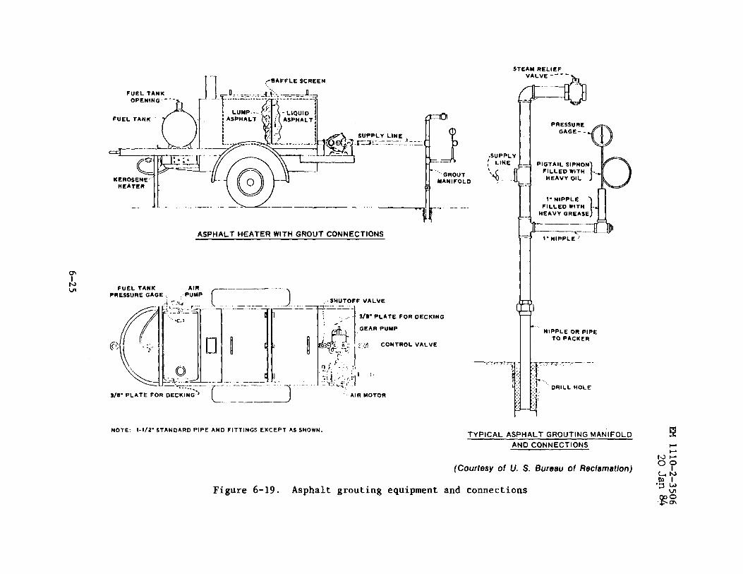
P“ Asphalt Grouting Equipment. Portable asphalt heating kettles commonlyused by contractors for pavement crack sealing, roofing coatings, and similarapplications have served well in heating asphalt for grouting (fig. 6-19). Hotasphalt heating should be maintained below the flash point of the asphalt.
6-24
STEAMRELIEF
FuEL TANKOPENING---
FUEL TANK ““’f\
KEROSENiHEATER
—...
1-1 ,> BAFFLE SCREEN
,SUPPL
~ LINE,,4..
1----......._-.--–u.—_–_ -. / ....... ..hASPHALT HEATER WITH GROUT CONNECTIONS
FuEL TANK —..—— .— ----
PREsSURE GAGE .Pt;P f- )SHUTOFF VALVE~’---- -——.
:.. I 3/O”PLATEFOROECKING
L.-——2
NOTE: l-f/2”STANOARDPlPEAND FITTINGS EXCEPT AS SHOWN.
AIR MOTOR
—
VALVE----
~--<l
—
(Courtesy of U.S.
Figure 6-19. Asphalt grouting equipment and connections
PRESSUREGAGE-.
HEAVY OIL
l-NIPPLE
HEAVY GREASE
...‘NIPPLE OR PIPE
TO PACKER
i
T.---—.—7. 7TS
;: :
::?.
51; DRILL HOLE
:. .,.::’.
TYPICAL ASPHALT GROUTING MANIFOLD E
AND CONNECTIONS --
w-
Bureau ofRec/amation)o?~y‘g:
gz

EM 1110-2-350620 Jan 84
Reciprocating pumps with ballgear pumps, have been used to
valves, or l-inch boiler-fed piston pumps andpump hot asphalt through 1- to 2-inch black iron
pipe. Conventional type cement grouting equipment can be used for asphaltemulsions.
q“ Chemical Grouting Equipment. Grouting equipment has been generallydeveloped by the manufacturer to mix and place that particular chemical groutsystem. Conventional grouting equipment may be used-for a number of pro~esses,especially when single batching will meet the job requirements. Closely con-trolled proportioning systems are frequently recommended for handling two ormore components of a given formulated grout. Detailed descriptions coveringchemical grouting equipment are discussed in EM 1110-2-3504.
r. Large-Capacity Mixing and Pumping Systems. During the middle yearsof the twentieth century, an enormous surge began to take place in the growthof organizations that have developed highly specialized equipment, materials,and techniques for grouting operations, especially those operations requiringlarge, continuous mixing and pumping systems. One single pumping system iscapable of mixing and placing approximately 35 cubic yards per hour. Pumpsare capable of developing 20,000 pounds per square inch. These capabilitieshave mainly been developed as a result of an increasing demand to solve under-ground problems associated with energy sources, large foundations, deeplyburied structures, and other grouting operations similar in scope and complex-ity. Much of the equipment used i~ these types of grouting operations ismobile; some systems are skid mounted and others are barge mounted. Companiesspecializing in large-scale grouting operations as well as oil well cementing/grouting companies are providing this type of grouting capability worldwide.Some of the major pieces of equipment and storage facilities used in large-capacity mixing and pumping systems are shown in figure 6-20.
s. Tremie Equipment. Steel sections of pipe and tubing fabricated froma few inches to as large—as 6 or more inches in diameter and to lengths rangingfrom a few feet to desired lengths are the major items that make up a tremiesystem for the gravity placement of grout. The sections are usually joinedloosely end to end by means of short lengths of steel-linked chain in forming
- a continuous and somewhat flexible pipe string. The tremie system with agathering hopper or chute attached to the top section is positioned initiallywith its discharge end immediately above the point of grout placement.
t. -“ The casing commonly used in grouting work is either steel orplastic tubing. The tubing is lowered into a borehole to prevent collapse ofthe hole or entry of loose rock, gas, or liquid or to prevent loss of circula-tion fluid into permeable formations. Casing is used to isolate zones to begrouted through perforated casing. Additional information regarding casing ispresented in EM 1110-2-1907 and EM 1110-2-3504.
u. ~ressure Testing Equipment. The major items of equipment normallyneeded to conduct pressure testing include single or straddle packers, a water
6-26

EM 1110-2-350620Jan %
Figure 6-20. Standard twin HT-400 cementing unit fully rigged with jetmixing cone and slurry reservoir. Courtesy, Halliburton Services
meter, a nonpulsating type pump, pressure gages, a suitable pipe or base forcomection to the hole collar or downhole, and a stop watch. Water meters and
pressure gages should be tested for accuracy prior to use as these items pro-vide essential numerical data for analysis.
v. Meters. An accurate and expeditious method of controlling groutwater contents is by using volume-measuring water meters. These meters can be
obtained with measurements in either gallons or cubic feet and can usually beread to the nearest quarter of a gallon or tenth of a cubic foot. A meter
should be checked for accuracy before.it is used and, if necessary, should becalibrated. Meters for measuring quantity of grout placements either may con-sist of something as simple as a vertical graduated stick or rod gages placed
6-27

EM 1110-2-350620 Jan d4
1-1, ADJ~T/NG SCREW
R 2, WING NUT
F
3, PACKING GUND
4. “’O RING
‘- 6, ‘TEF’
—
F12. OUTER PIPE WITH COUPLING.
S FT (l.&n)
13, INNER PIPE WITH mlJPLING,6 FT fl.6m)
k“8. RUBBER PACKER,LONG (2 REO”D)
7, WASHER (3 REO”D)
2 INCHES
Ly 9, PERFORA TED OUTER PIPE
r
F10, LOWER QUILL
7, SNAP RING
K8, RUBBER PACKER. 2 INCHESLONG (2 REQ’D)
7. WASHER (3 REQ;D)11. SNAP RING
Figure 6-21. Pressure testing packer assembly
6-28
EM 1110-2-350620 Jan 84
in mixers or agitator trucks, or may use calibrated spindles placed in thegrout line and geared to counters or strip recorders (fig. 6-21). Thesemeters may be designed to measure barrels, cubic feet, gallons, or fractionsof these units.
w. Pressure Gages.
(1) Pressure gages are essential in virtually all types of grouting andpressure testing, and they must be reliable. Malfunctioning gages have re-sulted in damage to structures and rock formations as a result of excessivepressures. Gages should be tested for accuracy prior to use and periodicallyduring the work. The moving parts of the gage should be protected from dustand grit and from direct contact with the grout.
(2) Gages that are available commercially consist of diaphragm systemsto provide the necessary protection. A diaphragm glycerin-filled gage saveris shown in figure 6-22.
6-3. Special Monitoring Equipment. A structure has precise, measurable dimen-sions in virtually all respects; however, the foundation of the structure canonly be described in general terms. The quality of grout being placed in thefoundation and the location, ❑ovement, and behavior of grout in place may needconstant monitoring during a grouting operation. Some of the monitoringmethods in use are described below.
a. Grout Level Detection Equipment. Monitoring the progress and ade-quacy of subsurface grouting operations is extremely important under some cir-cumstances; i.e., grouting voids under structures which must be completelyfilled with grout. Such monitoring can be accomplished by grout level detec-tion systems that include electronic readouts from probes located in an arrayof satellite drill holes surrounding the grout injection hole. The probesusually consist of electrode pairs that measure capacitance or resistance offreshly placed grouts. These probes, prior to placement downhole, are cali-brated in air, water, mud, diluted grout, and the designed grout. With thesedata available, the system can be used to determine the quality of the groutbeing placed, and its vertical and lateral movements. The data also provideinformation relative to decisions to modify mixtures during placement, such asto use a quicker or slower setting mixture, to increase or decrease density,to add lost circulation material, and to incorporate tracers. Remote record-ings can be obtained on printers or oscilloscopes. One application of groutlevel detection equipment is presented in WES MP SL-79-23 (app A).
b. Downhole Temperature Measurements. Temperature profiles of the sub-surface area to be grouted are very helpful in furnishing information on theanticipated effects of temperatures on the setting times of grouts. Thermo-couples or thermistors left in place will indicate the presence of grout as aresult of te~erature rise caused by the hydration of the cement or the reac-tion of the catalyst system in chemical grouts.
6-29

EM 1110-2-350620Jan 84
----,- -
I ==-- ‘W ‘HEAVY DUTY. .
PRESSURE GAGE--4’ L\
xm “$.l-1/2n PIPE WELDED ---
TO RING
1/4” PROTECTOR RINGS
WELOED TO PIPE
* T>
FILL WITH GLYCERIN -..-. 4
\ 0 -------------
-----~ ::=---T----.* ‘
/ --~-:-;i=
‘SPECIAL DUCK INSERTION ,IJ~--
% :& >RUBBER SHEET PACKING- s?---,
7-3-;
-:3-k
ELEVATION SECTION
DIAPHRAG
TOP VIEW BOTTOM VIEW
(Courtesy of U. S. Bureau of Reclamation)
Figure 6-22. Glycerin-filled gage saver
c. Downhole Sampler. A sampler that is useful in sampling grout todepths some few hundred feet downhole may be described as a small bottom-discharge bailer. It works on the same principle as the old-time water wellbottom-discharge bailer, which is composed of a metal tube approximately 1 to
2 feet in length and approximately 3 inches in diameter. The bailer has oneline for lowering and raising and one line for operating the valve located inthe bottom.
d. Tracer Materials. Color tracers used in water and grout can be help-ful in determining the extent of a groundwater or a grout communication system.Color pigments normally used in portland cement grouts as tracer materials are
6-30

EM 1110-2-35061!(JJar,34
basically finely ground iron and chromium oxides, which provide a wide rangeof distinct colors. Five to ten pounds of one of these pigments per sack ofcement is usually sufficient to produce a distinct color. Other dyes includefluoresceins and rhodamines. The manufacturer of the chemical grout to beused should be contacted as to type and concentration for use in a particularproduct.
e. Flow Cone. The flow cone measurement may be used both in the labora-tory and in the field for determining the flow of grout mixtures by measuringthe time of efflux of a specified volume of grout from a standard cone. Thistest is used to ascertain the fluidity of grout mixtures. The method of test-ing is covered in CRD-C 611.
f. Slurry Scales. The unit weight of grout mixtures may be determinedby using either the standard API-approved mud scale balance shown in fig-ure 6-23 or by a unit weight container, precisely calibrated, that ranges from0.25 to 1.0 cubic foot and has a set of scales graduated to tenths of a poundand a weighing capacity of at least 250 pounds.
g“ Densimeters. Densimeters are very helpful devices that are frequentlyused in large scope and continuous grouting operations for measuring and con-trolling the densities of grout mixtures. These units are normally placedin-line and ahead of the surface recirculating system to provide a means for
Figure 6-23. Mud balance
6-31

EM 1110-2-350620Ja~ 84
adjusting mixtures to designed densities. The devices operate on variousprinciples; one such device is designed on the principle of a force-balancedU-tube; a second operates on a radioactive source. Both systems are equippedwith remote continuous readouts.,
h. Slmp Cone. The consistency of very thick grouts may be determinedby measuring the slump. The cone is a metal frustum that has a base ofeight inches, a top of four inches, and a vertical height of 12 inches. Thegrout is placed in the cone in three equal layers, and each layer is rodded25 times. The cone is removed vertically, and the slump of the grout is mea-sured in inches from the top of the slump cone to the top of the grout. Thismethod of test for slump is described in CRD-C 5.
i. Air Content Measurements. There are five methods that may be usedfor determining the air content of portland cement grout mixtures: gravi-metric, high pressure, micrometric, pressure, and volumetric. These methodsare described, respectively, in CRD-C 7, C 83, C 42, C 41, and C 8. MethodsCRD-C 7, C 41, and C 8 are for freshly mixed grout and CRD-C 83-58 and C 42-83are for hardened grout air contents, usually determined in the laboratory.
j. Time-of-Setting Apparatus. The initial and final sets of portlandcement grouts are determined by the use of a mechanical device known as theVicat apparatus. The apparatus is designed to measure with time the depth ofpenetration or no penetration of a blunt needle into a small cuplike receptaclecontaining a sample of the grout. This test can be conducted in the labora-tory or field. The method of test is described in CRD-C 614.
6-32