Embed Size (px)
Citation preview
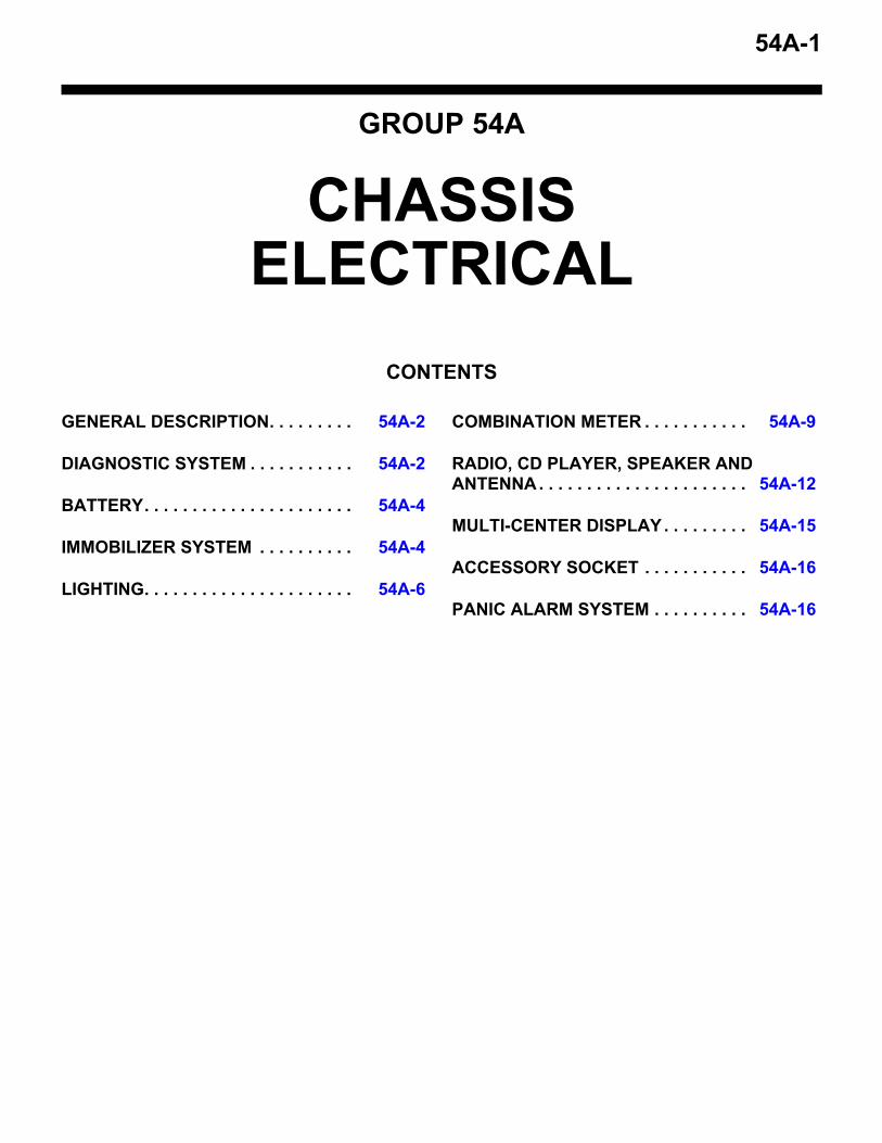
54A-1
GROUP 54A
CHASSIS ELECTRICAL
CONTENTS
GENERAL DESCRIPTION. . . . . . . . . 54A-2
DIAGNOSTIC SYSTEM . . . . . . . . . . . 54A-2
BATTERY. . . . . . . . . . . . . . . . . . . . . . 54A-4
IMMOBILIZER SYSTEM . . . . . . . . . . 54A-4
LIGHTING. . . . . . . . . . . . . . . . . . . . . . 54A-6
COMBINATION METER . . . . . . . . . . . 54A-9
RADIO, CD PLAYER, SPEAKER AND ANTENNA. . . . . . . . . . . . . . . . . . . . . . 54A-12
MULTI-CENTER DISPLAY. . . . . . . . . 54A-15
ACCESSORY SOCKET . . . . . . . . . . . 54A-16
PANIC ALARM SYSTEM . . . . . . . . . . 54A-16
GENERAL DESCRIPTIONCHASSIS ELECTRICAL54A-2
GENERAL DESCRIPTIONM2540000100432
FEATURES.
IMPROVEMENTS IN DESIGN• Inner-lens-type headlights and rear combination
lights• High-mounted stoplight integrated into the rear
spoiler• Motorcycle-type combination meter
.
IMPROVEMENTS IN VISIBILITY AND SAFETY• Large dual-lamp headlights with a lightweight
resin lenses• LEDs for the tail and stoplights in the rear combi-
nation lights• LEDs for the warning lights and night illumination
lights in the combination meter• LEDs for high-mounted stoplight
.
IMPROVEMENTS IN RELIABILITYSecure data transmission by connecting the combi-nation meter and ECUs with CAN
.
IMPROVEMENTS IN SERVICE QUALITY• Attachment of a data link connector for inspection
with MUT-III scan tool• Inset connector for the combination meter• Diagnosis and service data in the combination
meter, enabling communication with MUT-III scan tool
• Simplified Wiring System (SWS) to reduce weight and complexity of harnesses
.
IMPROVEMENTS IN MARKETABILITY• Immobilizer system• Panic alarm system• Rockford Fosgate high performance audio sys-
tem (premium audio system) as an option• Multi center display for viewing a variety of vehi-
cle data• Accessory sockets
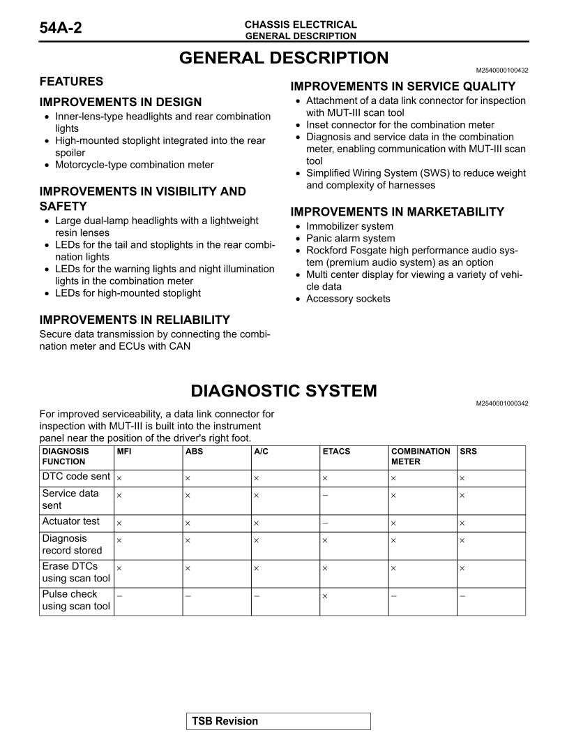
DIAGNOSTIC SYSTEMM2540001000342
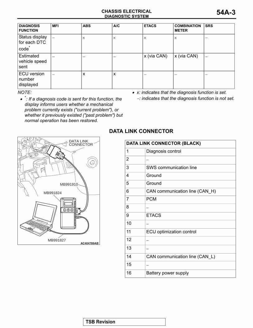
For improved serviceability, a data link connector for inspection with MUT-III is built into the instrument panel near the position of the driver's right foot.DIAGNOSIS FUNCTION
MFI ABS A/C ETACS COMBINATION METER
SRS
DTC code sent × × × × × ×
Service data sent
× × × − × ×
Actuator test × × × − × ×
Diagnosis record stored
× × × × × ×
Erase DTCs using scan tool
× × × × × ×
Pulse check using scan tool
− − − × − −
TSB Revision
DIAGNOSTIC SYSTEMCHASSIS ELECTRICAL 54A-3
NOTE: .• *: If a diagnosis code is sent for this function, the
display informs users whether a mechanical problem currently exists ("current problem"), or whether it previously existed ("past problem") but normal operation has been restored.
• x: indicates that the diagnosis function is set.−: indicates that the diagnosis function is not set.
DATA LINK CONNECTORAC305412
AC404789AB
DATA LINKCONNECTOR
MB991824
MB991827
MB991910
DATA LINK CONNECTOR (BLACK)1 Diagnosis control
2 −
3 SWS communication line
4 Ground
5 Ground
6 CAN communication line (CAN_H)
7 PCM
8 −
9 ETACS
10 −
11 ECU optimization control
12 −
13 −
14 CAN communication line (CAN_L)
15 −
16 Battery power supply
Status display for each DTC code*
− × × × × −
Estimated vehicle speed sent
− − − x (via CAN) x (via CAN) −
ECU version number displayed
− x x − − −
DIAGNOSIS FUNCTION
MFI ABS A/C ETACS COMBINATION METER
SRS
TSB Revision

BATTERYCHASSIS ELECTRICAL54A-4
BATTERYM2540002000345
ITEM BCI GROUP SIZE 86 BCI GROUP SIZE 24Voltage V 12 12Capacity (5-hour rate Ah) 50 56Electrolytic fluid specific gravity [fully charged state at 20°C (68°F)]
1.280 1.280
Reserve capacity min 90 115Cold cranking current A [at −18°C (0°F)] 525 550
IMMOBILIZER SYSTEMM2540003000315
The engine immobilizer system prevents the engine from starting and immobilizes the vehicle if a key other than the key registered for that vehicle is used in an attempt to start the engine after forced entry. The engine immobilizer system consists of the igni-tion key, the key ring antenna, the ETACS-ECU (immobilizer-ECU), and the engine control module (ECM) <M/T> or powertrain control module (PCM) <A/T>. It has these functions:
The system is designed to be maintenance-free because the power source for the transponder is supplied by the ETACS-ECU (immobilizer-ECU) via the key ring antenna. Two ignition keys are provided, and up to eight keys can be registered to one vehicle (one receiver) as needed. There are 4 billion combi-nations for the encrypted code. In addition, one part of the code is changed each time the key is switched on, which improves security by preventing theft using a copied encrypted code.
DIAGNOSIS CODE TABLECODE NUMBER TROUBLE CONTENTB1702 Reception error of transponder dataB1703 Transponder data inconsistentB1731 Reception error of CAN dataB1761 VIN not recorded
CONSTRUCTION DIAGRAM
AC406526AB
IGNITION KEY KEY RING ANTENNA
ETACS-ECU(IMMOBILIZER-ECU) ECM <M/T> OR PCM <A/T>
IGNITION
INJECTION
CAN-BUS
CPU
ENCRYPTED CODE
CPUTRANS-PONDER
TSB Revision
IMMOBILIZER SYSTEMCHASSIS ELECTRICAL 54A-5
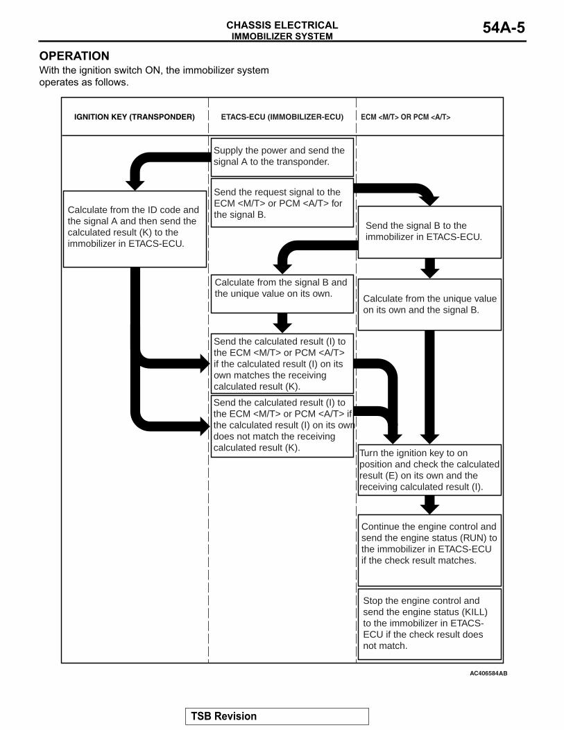
OPERATIONWith the ignition switch ON, the immobilizer system operates as follows.
AC406584
Supply the power and send the signal A to the transponder.
Send the request signal to the ECM <M/T> or PCM <A/T> for the signal B.Calculate from the ID code and
the signal A and then send the calculated result (K) to the immobilizer in ETACS-ECU.
Send the signal B to the immobilizer in ETACS-ECU.
Calculate from the unique value on its own and the signal B.
Calculate from the signal B and the unique value on its own.
Send the calculated result (I) to the ECM <M/T> or PCM <A/T> if the calculated result (I) on its own matches the receiving calculated result (K).
Send the calculated result (I) to the ECM <M/T> or PCM <A/T> if the calculated result (I) on its own does not match the receiving calculated result (K). Turn the ignition key to on
position and check the calculated result (E) on its own and the receiving calculated result (I).
Continue the engine control and send the engine status (RUN) to the immobilizer in ETACS-ECU if the check result matches.
Stop the engine control and send the engine status (KILL) to the immobilizer in ETACS-ECU if the check result does not match.
AB
ECM <M/T> OR PCM <A/T>ETACS-ECU (IMMOBILIZER-ECU)IGNITION KEY (TRANSPONDER)
TSB Revision
LIGHTINGCHASSIS ELECTRICAL54A-6
LIGHTINGM2540004000534
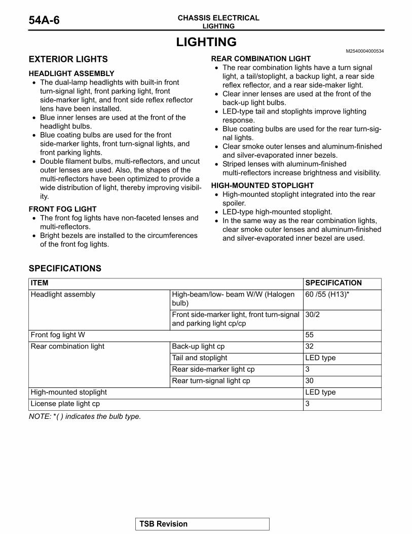
EXTERIOR LIGHTSHEADLIGHT ASSEMBLY• The dual-lamp headlights with built-in front
turn-signal light, front parking light, front side-marker light, and front side reflex reflector lens have been installed.
• Blue inner lenses are used at the front of the headlight bulbs.
• Blue coating bulbs are used for the front side-marker lights, front turn-signal lights, and front parking lights.
• Double filament bulbs, multi-reflectors, and uncut outer lenses are used. Also, the shapes of the multi-reflectors have been optimized to provide a wide distribution of light, thereby improving visibil-ity.
FRONT FOG LIGHT• The front fog lights have non-faceted lenses and
multi-reflectors.• Bright bezels are installed to the circumferences
of the front fog lights.
REAR COMBINATION LIGHT• The rear combination lights have a turn signal
light, a tail/stoplight, a backup light, a rear side reflex reflector, and a rear side-maker light.
• Clear inner lenses are used at the front of the back-up light bulbs.
• LED-type tail and stoplights improve lighting response.
• Blue coating bulbs are used for the rear turn-sig-nal lights.
• Clear smoke outer lenses and aluminum-finished and silver-evaporated inner bezels.
• Striped lenses with aluminum-finished multi-reflectors increase brightness and visibility.
HIGH-MOUNTED STOPLIGHT• High-mounted stoplight integrated into the rear
spoiler.• LED-type high-mounted stoplight.• In the same way as the rear combination lights,
clear smoke outer lenses and aluminum-finished and silver-evaporated inner bezel are used.
.
SPECIFICATIONSITEM SPECIFICATIONHeadlight assembly High-beam/low- beam W/W (Halogen
bulb)60 /55 (H13)*
Front side-marker light, front turn-signal and parking light cp/cp
30/2
Front fog light W 55Rear combination light Back-up light cp 32
Tail and stoplight LED typeRear side-marker light cp 3Rear turn-signal light cp 30
High-mounted stoplight LED typeLicense plate light cp 3
NOTE: *( ) indicates the bulb type..
TSB Revision
LIGHTINGCHASSIS ELECTRICAL 54A-7
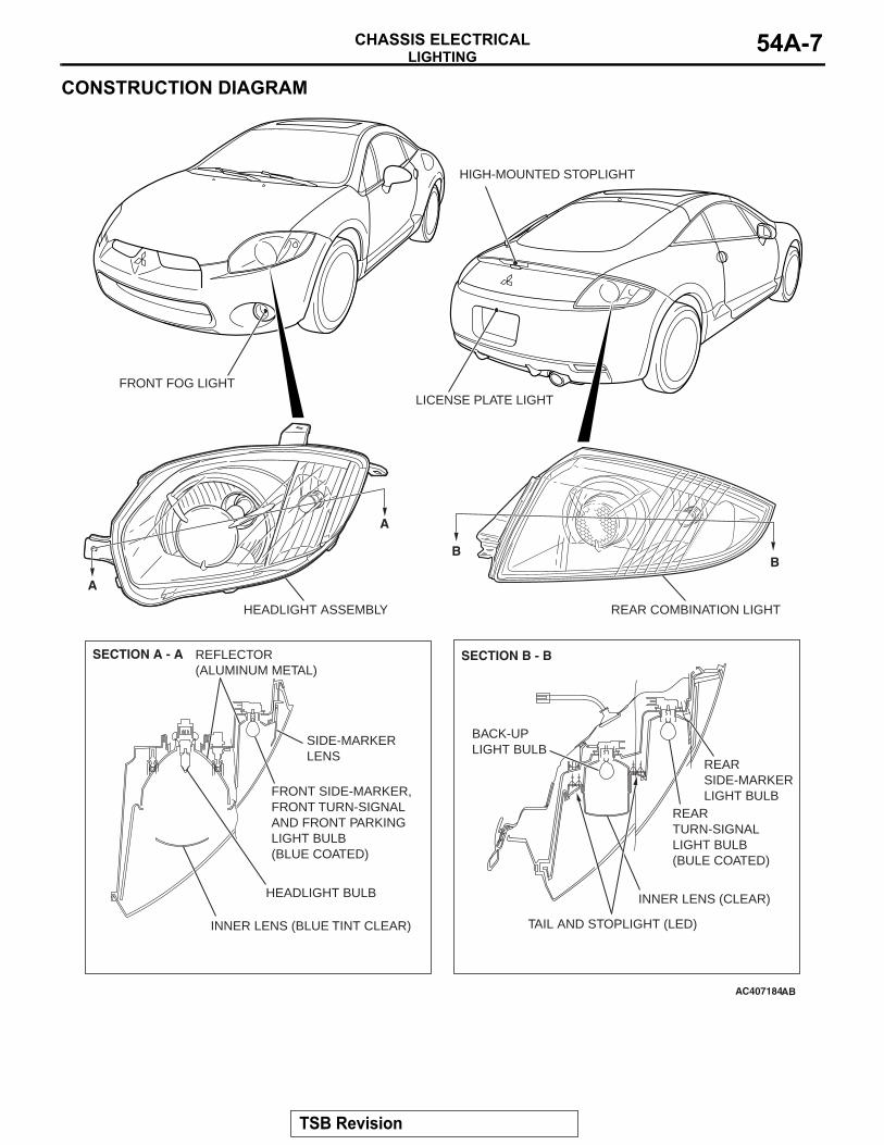
CONSTRUCTION DIAGRAM
AC407184
FRONT FOG LIGHTLICENSE PLATE LIGHT
HIGH-MOUNTED STOPLIGHT
A
A
SECTION A - A
HEADLIGHT ASSEMBLY
REFLECTOR (ALUMINUM METAL)
HEADLIGHT BULB
FRONT SIDE-MARKER, FRONT TURN-SIGNALAND FRONT PARKING LIGHT BULB (BLUE COATED)
SIDE-MARKERLENS
INNER LENS (BLUE TINT CLEAR)
AB
BB
SECTION B - B
REAR COMBINATION LIGHT
REAR TURN-SIGNAL LIGHT BULB (BULE COATED)
REAR SIDE-MARKER LIGHT BULB
TAIL AND STOPLIGHT (LED)
INNER LENS (CLEAR)
BACK-UPLIGHT BULB
TSB Revision

LIGHTINGCHASSIS ELECTRICAL54A-8
INTERIOR LAMPS• The inside rear view mirror with the built-in front
dome lights. <Vehicles with sunroof>• Front dome lights above the front seats. <Vehi-
cles without sunroof>
• Rear dome light above the rear seat.• Luggage compartment light above the luggage
compartment.• Vanity mirror lights on the vanity mirrors.• Glove box light in the glove box.
.
SPECIFICATIONSITEM SPECIFICATIONFront dome light W × quantity <Vehicles without sunroof> 5 × 2Inside rear view mirror assembly Front dome light W × quantity
<Vehicles with sunroof>5 × 2
Rear dome light W 8Luggage compartment light W 5Vanity mirror light W 1.4 × 2Glove box light W 1.4
.
CONSTRUCTION DIAGRAM
AC407066AB
REAR DOME LIGHT
VANITY MIRROR LIGHT
LEFT MAP LIGHT RIGHT MAP
LIGHT
LUGGAGE COMPARTMENT LIGHT
FRONT DOME LIGHT
FRONT DOME LIGHT
LEFT MAP LIGHT
RIGHT MAP LIGHT
<VEHICLES WITHOUT SUNROOF>
<VEHICLES WITH SUNROOF>
GLOVE BOX LIGHT
TSB Revision
COMBINATION METERCHASSIS ELECTRICAL 54A-9
COMBINATION METERM2540005000548
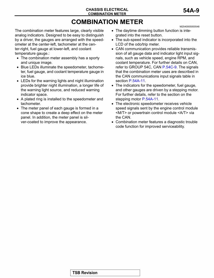
The combination meter features large, clearly visible analog indicators. Designed to be easy to distinguish by a driver, the gauges are arranged with the speed-ometer at the center-left, tachometer at the cen-ter-right, fuel gauge at lower-left, and coolant temperature gauge.:• The combination meter assembly has a sporty
and unique image.• Blue LEDs illuminate the speedometer, tachome-
ter, fuel gauge, and coolant temperature gauge in ice blue.
• LEDs for the warning lights and night illumination provide brighter night illumination, a longer life of the warning light source, and reduced warning indicator space.
• A plated ring is installed to the speedometer and tachometer.
• The meter panel of each gauge is formed in a cone shape to create a deep effect on the meter panel. In addition, the meter panel is sil-ver-coated to improve the appearance.
• The daytime dimming button function is inte-grated into the reset button.
• The sub-speed indicator is incorporated into the LCD of the odo/trip meter.
• CAN communication provides reliable transmis-sion of all gauge data and indicator light input sig-nals, such as vehicle speed, engine RPM, and coolant temperature. For further details on CAN, refer to GROUP 54C, CAN P.54C-9. The signals that the combination meter uses are described in the CAN communications input signals table in section P.54A-11.
• The indicators for the speedometer, fuel gauge, and other gauges are driven by a stepping motor. For further details, refer to the section on the stepping motor P.54A-11.
• The electronic speedometer receives vehicle speed signals sent by the engine control module <M/T> or powertrain control module <A/T> via the CAN.
• Combination meter features a diagnostic trouble code function for improved serviceability.
TSB Revision
COMBINATION METERCHASSIS ELECTRICAL54A-10
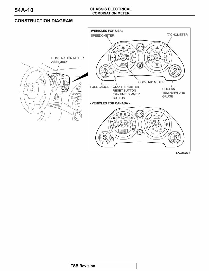
CONSTRUCTION DIAGRAM
AC407069
COMBINATION METER ASSEMBLY
AB
SPEEDOMETER TACHOMETER
FUEL GAUGECOOLANT TEMPERATURE GAUGE
ODO-TRIP METER
<VEHICLES FOR USA>
<VEHICLES FOR CANADA>
ODO-TRIP METER RESET BUTTON/DAYTIME DIMMER BUTTON
TSB Revision
COMBINATION METERCHASSIS ELECTRICAL 54A-11
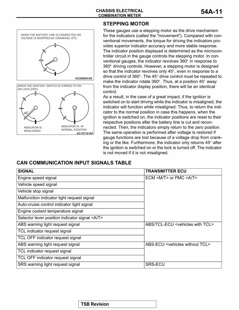
STEPPING MOTOR
AC208264AE
WHEN THE BATTERY LINE IS CONNECTED OR VOLTAGE IS DROPPED BY CRANKING, ETC.
AC107161AF
45˚
WHEN THE IGNITION SWITCH IS TURNED TO ONOR LOCK (OFF).
INDICATOR IS MISALIGNED
INDICATOR IS AT NORMAL POSITION
These gauges use a stepping motor as the drive mechanism for the indicators (called the "movement"). Compared with con-ventional movements, the torque for driving the indicators pro-vides superior indicator accuracy and more stable response. The indicator position displayed is determined as the microcon-troller circuit in the gauge controls the stepping motor. In con-ventional gauges, the indicator revolves 360° in response to 360° driving controls. However, a stepping motor is designed so that the indicator revolves only 45°, even in response to a drive control of 360°. The 45° drive control must be repeated to make the indicator rotate 360°. Thus, at a position 45° away from the indicator display position, there will be an identical control.As a result, in the case of a great impact, if the ignition is switched on to start driving while the indicator is misaligned, the indicator will function while misaligned. Thus, to return the indi-cator to the normal position in case this happens, when the ignition is switched on, the indicator positions are reset to their respective positions after the battery line is cut and recon-nected. Then, the indicators simply return to the zero position. The same operation is performed after voltage is restored if gauge functions are lost because of a voltage drop from crank-ing or the like. Furthermore, the indicator only returns 45° after the ignition is switched on or the lock is turned off. The indicator is not moved if it is not misaligned.
CAN COMMUNICATION INPUT SIGNALS TABLESIGNAL TRANSMITTER ECUEngine speed signal ECM <M/T> or PMC <A/T>Vehicle speed signalVehicle stop signalMalfunction indicator light request signalAuto-cruise control indicator light signalEngine coolant temperature signalSelector lever position indicator signal <A/T>ABS warning light request signal ABS/TCL-ECU <vehicles with TCL>TCL indicator request signalTCL OFF indicator request signalABS warning light request signal ABS-ECU <vehicles without TCL>TCL indicator request signalTCL OFF indicator request signalSRS warning light request signal SRS-ECU
TSB Revision
RADIO, CD PLAYER, SPEAKER AND ANTENNACHASSIS ELECTRICAL54A-12
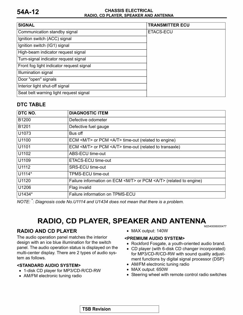
DTC TABLEDTC NO. DIAGNOSTIC ITEMB1200 Defective odometerB1201 Defective fuel gaugeU1073 Bus offU1100 ECM <M/T> or PCM <A/T> time-out (related to engine)U1101 ECM <M/T> or PCM <A/T> time-out (related to transaxle)U1102 ABS-ECU time-outU1109 ETACS-ECU time-outU1112 SRS-ECU time-outU1114* TPMS-ECU time-outU1120 Failure information on ECM <M/T> or PCM <A/T> (related to engine)U1206 Flag invalidU1434* Failure information on TPMS-ECU
NOTE: *: Diagnosis code No.U1114 and U1434 does not mean that there is a problem.
RADIO, CD PLAYER, SPEAKER AND ANTENNAM2540006000477
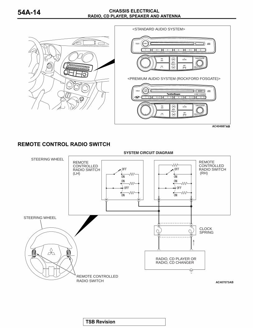
RADIO AND CD PLAYERThe audio operation panel matches the interior design with an ice blue illumination for the switch panel. The audio operation status is displayed on the multi-center display. There are 2 types of audio sys-tem as follows.
<STANDARD AUDIO SYSTEM>• 1-disk CD player for MP3/CD-R/CD-RW• AM/FM electronic tuning radio
• MAX output: 140W
<PREMIUM AUDIO SYSTEM>• Rockford Fosgate, a youth-oriented audio brand.• CD player (with 6-disk CD changer incorporated)
for MP3/CD-R/CD-RW with sound quality adjust-ment functions by digital signal processor (DSP)
• AM/FM electronic tuning radio• MAX output: 650W • Steering wheel with remote control radio switches
Communication standby signal ETACS-ECUIgnition switch (ACC) signalIgnition switch (IG1) signalHigh-beam indicator request signalTurn-signal indicator request signalFront fog light indicator request signalIllumination signalDoor "open" signalsInterior light shut-off signalSeat belt warning light request signal
SIGNAL TRANSMITTER ECU
TSB Revision
RADIO, CD PLAYER, SPEAKER AND ANTENNACHASSIS ELECTRICAL 54A-13
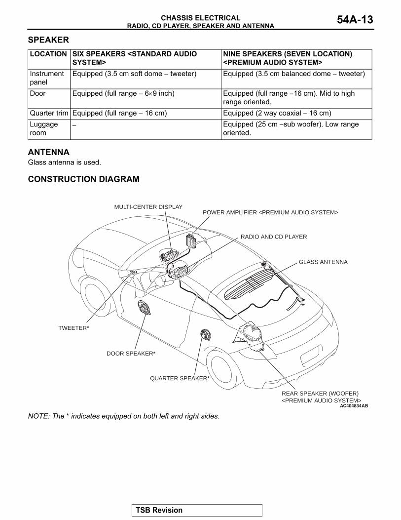
SPEAKERLOCATION SIX SPEAKERS <STANDARD AUDIO
SYSTEM>NINE SPEAKERS (SEVEN LOCATION) <PREMIUM AUDIO SYSTEM>
Instrument panel
Equipped (3.5 cm soft dome − tweeter) Equipped (3.5 cm balanced dome − tweeter)
Door Equipped (full range − 6×9 inch) Equipped (full range −16 cm). Mid to high range oriented.
Quarter trim Equipped (full range − 16 cm) Equipped (2 way coaxial − 16 cm)Luggage room
− Equipped (25 cm −sub woofer). Low range oriented.
ANTENNAGlass antenna is used.
CONSTRUCTION DIAGRAM.
AC404834
POWER AMPLIFIER <PREMIUM AUDIO SYSTEM>
GLASS ANTENNA
QUARTER SPEAKER*
REAR SPEAKER (WOOFER) <PREMIUM AUDIO SYSTEM>
DOOR SPEAKER*
TWEETER*
AB
RADIO AND CD PLAYER
MULTI-CENTER DISPLAY
NOTE: The * indicates equipped on both left and right sides..
TSB Revision
RADIO, CD PLAYER, SPEAKER AND ANTENNACHASSIS ELECTRICAL54A-14
AC404887AB
<STANDARD AUDIO SYSTEM>
<PREMIUM AUDIO SYSTEM (ROCKFORD FOSGATE)>
.
REMOTE CONTROL RADIO SWITCH
AC407073
RADIO, CD PLAYER OR RADIO, CD CHANGER
REMOTE CONTROLLEDRADIO SWITCH (RH)
CLOCKSPRING
REMOTE CONTROLLEDRADIO SWITCH (LH)
REMOTE CONTROLLED RADIO SWITCH
STEERING WHEEL
STEERING WHEEL
SYSTEM CIRCUIT DIAGRAM
AB
TSB Revision
MULTI-CENTER DISPLAYCHASSIS ELECTRICAL 54A-15
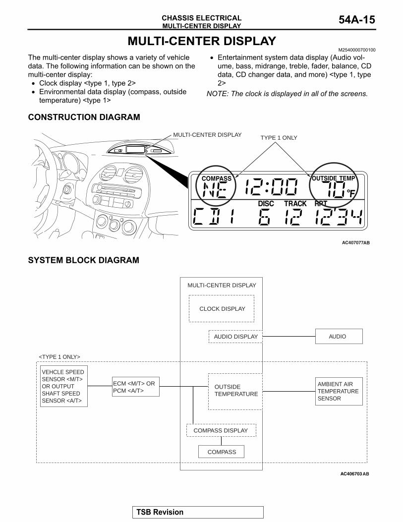
MULTI-CENTER DISPLAYM2540000700100
The multi-center display shows a variety of vehicle data. The following information can be shown on the multi-center display:• Clock display <type 1, type 2>• Environmental data display (compass, outside
temperature) <type 1>
• Entertainment system data display (Audio vol-ume, bass, midrange, treble, fader, balance, CD data, CD changer data, and more) <type 1, type 2>
NOTE: The clock is displayed in all of the screens.
CONSTRUCTION DIAGRAM
AC407077AB
MULTI-CENTER DISPLAY TYPE 1 ONLY
SYSTEM BLOCK DIAGRAM
AC406703AB
MULTI-CENTER DISPLAY
CLOCK DISPLAY
OUTSIDE TEMPERATURE
AUDIO DISPLAY
COMPASS DISPLAY
AMBIENT AIRTEMPERATURESENSOR
AUDIO
COMPASS
ECM <M/T> OR PCM <A/T>
VEHCLE SPEEDSENSOR <M/T>OR OUTPUT SHAFT SPEED SENSOR <A/T>
<TYPE 1 ONLY>
TSB Revision
ACCESSORY SOCKETCHASSIS ELECTRICAL54A-16
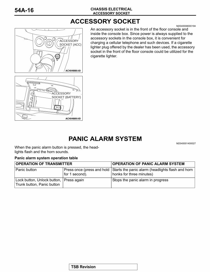
ACCESSORY SOCKETM2540008000194
AC404888AB
ACCESSORY SOCKET (ACC)
AC404889AB
ACCESSORY SOCKET (BATTERY)
An accessory socket is in the front of the floor console and inside the console box. Since power is always supplied to the accessory sockets in the console box, it is convenient for charging a cellular telephone and such devices. If a cigarette lighter plug offered by the dealer has been used, the accessory socket in the front of the floor console could be utilized for the cigarette lighter.
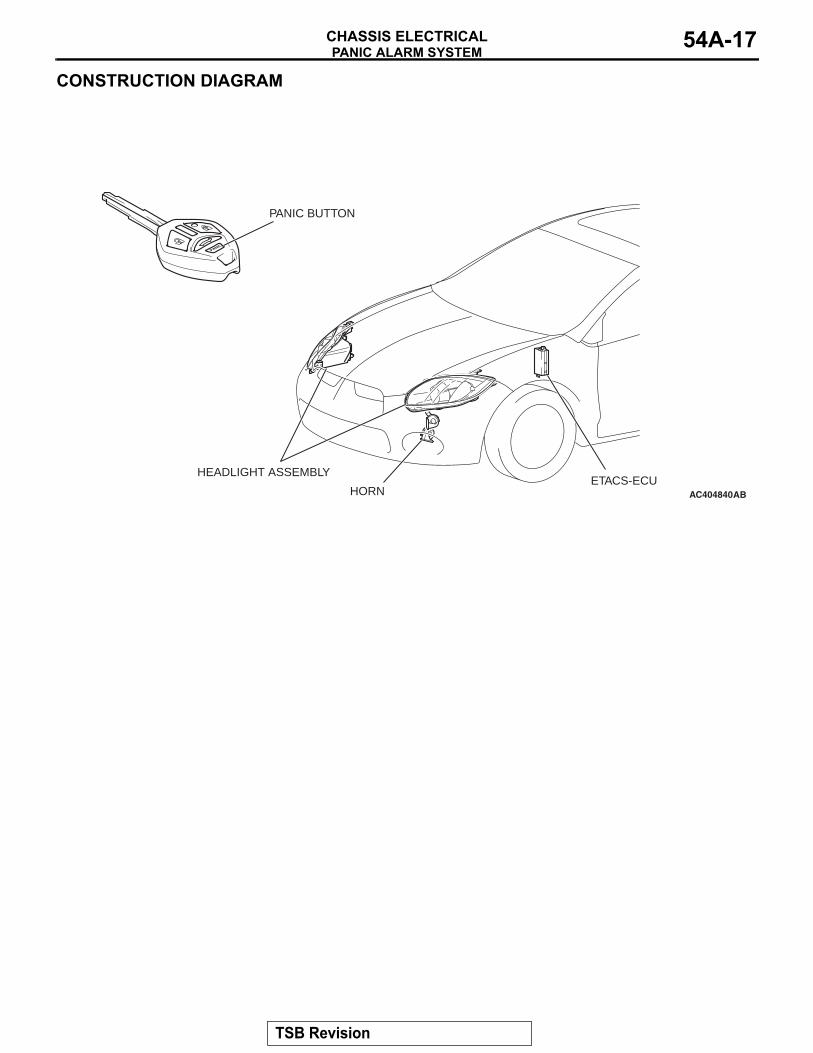
PANIC ALARM SYSTEMM2540001400027
When the panic alarm button is pressed, the head-lights flash and the horn sounds. Panic alarm system operation tableOPERATION OF TRANSMITTER OPERATION OF PANIC ALARM SYSTEMPanic button Press once (press and hold
for 1 second).Starts the panic alarm (headlights flash and horn honks for three minutes)
Lock button, Unlock button, Trunk button, Panic button
Press again Stops the panic alarm in progress
TSB Revision
PANIC ALARM SYSTEMCHASSIS ELECTRICAL 54A-17
CONSTRUCTION DIAGRAM
AC404840AB
PANIC BUTTON
HORN
HEADLIGHT ASSEMBLYETACS-ECU
TSB Revision

NOTES