Embed Size (px)
Citation preview

41849-G159-024
GROUND SOFTWAREMAINTENANCE FACILITY(GSMF) SYSTEM MANUAL
Final
26 February 1986{MS&-CB-1738Q4) G R O U N D SOFISAB* N86-25143
a a i N T E N A N C E FACILITY (GS!3F) SXS1EB H & N U A LFinal fieport (Tf iW Systems Group, Huntsville,Ala. ) 78 p HC S05/MF A01 CSCL 09B Ufldas
G3/61 42921
\
TRW HUNTSVILLE OPERATIONS213WYNN DRIVEHUNTSVILLE, ALABAMA 35805
https://ntrs.nasa.gov/search.jsp?R=19860015672 2018-07-01T05:48:25+00:00Z

i Development Division 213 Wynn Drivebnse Systems Group Huntsville. Alabama 35805
205-837-2400
SN41849.000G002.VOB.86-606828 February 1986
McDonnell Douglas Astronautics Co.Huntsville DivisionP.O. Box 1181Huntsville, Alabama 35807
ATTENTION: MR. U. R. LOKKEN
SUBJECT: SUBCONTRACT 83916018, GSMF DELIVERABLES,
Dear Mr. Lokken,
Per Supplemental Agreement 04, paragraph 4.2 of the June1984 revised Statement of Work, enclosed are the followingfinal reports and baselined software:
Detailed Design Document (Final)Users Manual (Final)System Manual (Final)GSMF Baselined SoftwareAcceptance Review Demonstration Package
If you should have any questions, please contact Mr. GarryGriffith at MSFC, Building 4708/B26A or telephone (205)453-3910.
TRW Inc.Defense Systems Group
V. O'L. BainContracts ManagerSystem Development Division
Encl: As Stated
cc: V. 0. Bain M. E. Hollowich TRW File (2)N. L. Blanks G. M. Lide V. A. WulffF. P. Herring G. C. Hitt
Delivery Package Received by:
W. R. Lokken, Branch Chief DateSoftware and Ground Computer SystemsMDAC-HSV
TRW Inc.

41849-G159-024 JMVJHMJMJT
tt\WW
GROUND SOFTWAREMAINTENANCE FACILITY(GSMF) SYSTEM MANUAL
Final
26 February 1986
PREPARED BY:
D. DerrigG. Griffith
J. E. ifby. GSMF /Review Authority
APPROVED BY:
//wM. E. HollowichProject Manager
TRW HUNTSVILLE OPERATIONS213WYNN DRIVEHUNTSVILLE, ALABAMA 35805

CONTENTS
Page
1. SCOPE 1-1
1.1 IDENTIFICATION . 1-11.2 ORGANIZATION 1-1
2. APPLICABLE DOCUMENTS 2-1
2.1 PROGRAM DOCUMENTS 2-12.2 GOVERNMENT DOCUMENTS 2-12.3 NON-GOVERNMENT DOCUMENTS 2-1
3. GSMF OVERVIEW 3-1
3.1 GSMF HARDWARE CONFIGURATION 3-13.2 GSMF SOFTWARE CONFIGURATION 3-2
3.2.1 Display Control . 3-53.2.2 Setup Mode 3-53.2.3 Simulation Mode 3-63.2.4 Test Mode 3-63.2.5 Post Processing 3-6
3.3 SOFTWARE BLOCK DIAGRAMS 3-7
4. SOFTWARE STRUCTURE 4-14.1 PROGRAMMING LANGUAGE 4-54.2 TIMING REQUIREMENTS 4-54.3 PROCESSING . 4-8
4.3.1 Supporting Goal Procedures 4-8
4.4 PERIPHERALS UTILIZED 4-8
4.4.1 Video Display Terminals 4-84.4.2 Line Printer 4-104.4.3 Tape Drives 4-10
4.5 INTERFACES 4-10
4.5.1 Processor-to-Processor Interface 4-104.5.2 VMEBUS Interface 4-12
4.6 DESCRIPTION OF MODULES 4-12
4.6.1 Source Files 4-12
4.6.1.1 Application Software Generation 4-134.6.1.2 Application Software Overview 4-20
4.6.2 Link Information 4-28
ii
CONTENTS (Cont inued)
Page
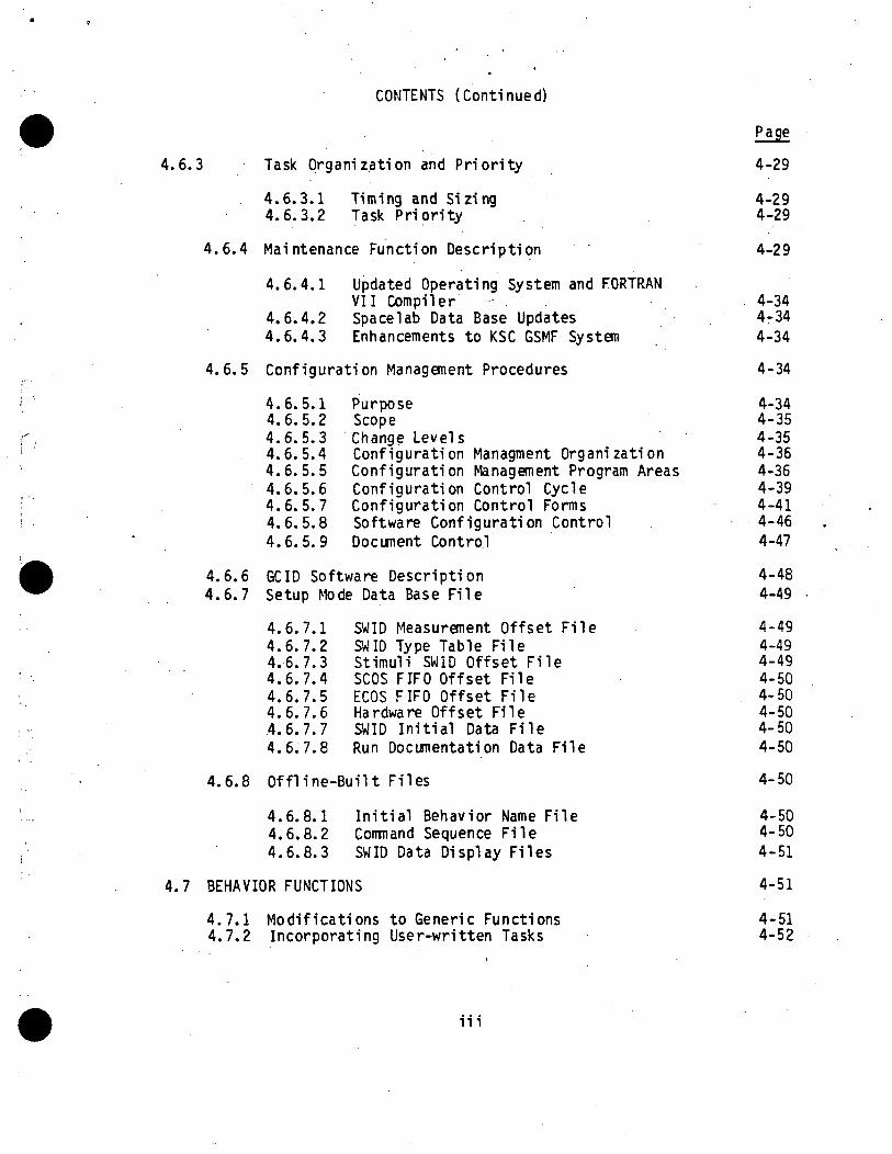
4.6.3 Task Organizat ion and Priority 4-29
4.6.3.1 Timing and Sizing 4-294.6.3.2 Task Priority 4-29
4.6.4 Maintenance Function Description 4-29
4.6.4.1 Updated Operating System and FORTRANVII Compiler . 4-34
4.6.4.2 Space!ab Data Base Updates 4-344.6.4.3 Enhancements to KSC GSMF System 4-34
4.6.5 Conf igura t ion Management Procedures 4-34
4.6.5.1 Purpose 4-344.6.5.2 Scope 4-354.6.5.3 Change Levels 4-354.6.5.4 Conf igura t ion Managment Organizat ion 4-364.6.5.5 Conf igura t ion Management Program Areas 4-364.6.5.6 Configurat ion Control Cycle 4-394.6.5.7 Conf igura t ion Control Forms 4-414.6.5.8 Software Configuration Control 4-464.6.5.9 Document Control 4-47
4.6.6 GCID Software Description 4-484.6.7 Setup Mode Data Base File 4-49
4.6.7.1 SWID Measurement Offset F i le 4-494.6.7.2 SWID Type Table File 4-494.6.7.3 Stimuli SWID Offset F i l e 4-494.6.7.4 SCOS FIFO Offset File 4-504.6.7.5 ECOS FIFO Offset File 4-504.6.7.6 Hardware Offset File 4-50.4.6.7.7 SWID Ini t ia l Data F i le 4-504.6.7.8 Run Documentation Data File 4-50
4.6.8 Offline-Built Files 4-50
4.6.8.1 Ini t ia l Behavior Name File 4-504.6.8.2 Command Sequence Fi le 4-504.6.8.3 SWID Data Display Files 4-51
4.7 BEHAVIOR FUNCTIONS 4-51
4.7.1 Modif icat ions to Generic Functions 4-514.7.2 Incorporating User-written Tasks 4-52
m

CONTENTS (Continued)
5. FAULT ISOLATION 5-1
5.1 GCID HARDWARE 5-15.2 PE-TEST MODE 5-15.3 PPI LOOP BACK TEST 5-15.4 ITTS SOFTWARE 5-15.5 VALIDATION SOFTWARE 5-25.6 SIMULATION MODE PERFORMANCE MONITOR 5-2
IV

LIST OF FIGURE-S
Page
3-1 GSMF Simulation Configuration 3-3
3-2 GSMF Simulation Mode Block Diagram 3-8
3-3 GSMF Offline File Build .3-9
3-4 Post Processing Software Block Diagram 3-10
4-1 GSMF Simulation Data Interface 4-2
4-2 MSE Stimuli Processing 4-3
4-3 SCCD Command Processing 4-4
4-4 TLC Command Processing 4-6
4-5 BSR Interrupt Processing 4-7
4-6 GSMF Change Control Process Flowchart 4-37

LIST OF TABLES,
Page
3-1 GSMF Host Computer Hardware Components 3-44-1 GSMF Accounts 4-154-2 Simulation Mode Accounts 4-164-3 Post Processor Account 4-194-4 Timing Estimates (Standalone Mode) 4-304-5 Measured Response Times (No Logging) 4-314-6 Memory Usage and Sizing 4-324-7 GSMF Host Task Priorities 4-334-8 User-Written Behavior Task Framework 4-53
VI

ACRONYMS
ATE Automatic Test Equipment
CCB Configuration Control Board
CM Configuration Management
CPC Computer Program Components
CRC Cyclic Redundancy Check
CRT Cathode Ray Tube
ECP Engineering Change Proposal
ECOS Experiment Computer Operating System
EGSE Electrical Ground Support Equipment
EOM End of Message
GCID Ground Computer Interface Device
GCOS Ground Computer Operating System
GMT Greenwich Mean Time
GOAL Ground Operation Aerospace Language
ITTS Integration and Test/Troubleshooting Software
MET Mission Elasped Time
MSE Measurement Stimulus Equipment
MSFC George C. Marshall Space Flight Center
NASA National Aeronautics and Space Administration
OS Operating System
P-E Perkin-Elmer (specifically, the Perkin-Elmer 3250 GSMF hostcomputer)
PIOL Periodic Input/Output Loop
PPI Processor-to-Processor Interface
QA Quality Assurance
vii

ACRONYMS (Continued)
SCCD Status Concentrator - Command Distributor
SCN Software Change Notice
SCOS Subsystem Computer Operating System
SDF Software Development Facility
SL Spacelab
SLBD Spacelab Data Base
SMID Simulation Indentification
SOM Start of Message
SPM Sub Project Manager
SPR Software Problem Reports
SPS Send PPI Status
SWID Software Identification
1MB Telemetry Buffer
UDF Unit Development Folder
VMEBUS A bus structure supporting the Motorola MC68000 Micro Processor
VMEB1 VME Bus Interface
vm

i. SCOPE
1.1 IDENTIFICATION
This document shall be the Ground Software Maintenance Facility (GSMF)
System Manual. The Ground Software Maintenance Facility (GSMF) is designed to
support development and maintenance of Spacelab ground support software. TheGSMF consists of a Perkin Elmer 3250 (Host computer) and a MITRA 125s (ATEcomputer), with appropriate interface devices and software to simulate theElectrical Ground Support Equipment (EGSE). A Ground Computer Interface Device(GCID) is the physical interface between the host computer and the ATEcomputer. The GSMF can operate in either a standalone or an integrated mode.In the standalone mode the GSMF emulates the Subsystem Computer OperatingSystem (SCOS) and/or the Experiment Computer Operating System (ECOS) activ-
ities. In the integrated mode, the Software Development Facilities (SDF)
running either SCOS and/or ECOS are linked to the simulation via the
Processor-to-Processor Interface (PPI). In the integrated mode the GSMFsupports flight software development.
The GSMF facility is located at the Marshall Space Flight Center (MSFC),Redstone Arsenal, in Huntsville, Alabama. Building 4708 houses the facilityin a laboratory which also includes the SDFs and the Instrument PointingSystem (IPS) simulation.
1.2 ORGANIZATION
This document is presented in three Sections, 1) GSMF Overview, 2)
Software Structure, and 3) Fault Isolation Capability. The overview contains
information on hardware and software organization along with their corre-sponding block diagrams. The Software Structure section describes the modesof software structure including source files, link information, and data basefiles. The Fault Isolation section describes the capabilities of the GCID,Perkin Elmer host, and MITRA ATE.
1-1

2. APPLICABLE DOCUMENTS
2.1 PROGRAM DOCUMENTS
a) GSMF Host Computer Detailed Software Requirements, TRW, 14 December1984
b) GSMF User 's Manual, TRW, 17 February 1986
c) GSMF Acceptance Test Plan, TRW, 18 March 1985
d) GSMF Software Detailed Design Document, TRW, 17 February 1986
e) TRW Software Test Management Series, October 1977
f) TRW Software Product Standards, 28 February 1977
g) TRW Configuration Management and Quality Assurance Manuals
2.2 GOVERNMENT DOCUMENTS
a) ECP for the SDF and PCU Updates - NA31 (83-350) - Marshall SpaceFlight Center - 14 July 1983
b) SPACE SHUTTLE INTERFACE CONTROL DOCUMENT .LEVEL II - ICD-2-05301 -Johnson Space Center - 17 December 1975
c) MIL-STD-483, Configuration Management Practices for SystemsEquipment, Munitions, and Computer Programs, 31 December 1968
2.3 NON-GOVERNMENT DOCUMENTS
a) TRW SOW for Expanded SDF - A90-ACIS-83451 - McDonnell DouglasTechnical Services Company - 31 August 1983
b) Space!ab Project SDF and PCU Expansion Proposal - 41849.007 - TRW -19 September 1983
c) Ground Software Maintenance Facility Hardware Requirements - 9004772- McDonnell Douglas Technical Services Company - 3 May 1984
d) Ground Software Maintenance Facility Software Requirements - 9004771- McDonnell Douglas Technical Services Company - 3 May 1984
e) Ground Software Maintenance Facility Interface Control Document -Acurex - 16 July 1984
f) Ground Software Maintenance Facility Preliminary Design Review -IC/FSD-84-026 - Intergraph Corporation - 23 July 1984
2-1

g) FUNCTIONAL SPECIFICATION VME BUS INTERFACE (VMEBI) - 03755R01Perkin-Elmer -27 April 1983
h) Processor-to-Processor Interface User's Manual - 99-736R04 -Perkin-Elmer - April 1976
i) PAYLOAD CHECKOUT UNIT (PCU) APPLICATION SOFTWARE USER'S GUIDE7940054C - IBM Federal Systems Division - 13 February. 1984
2-2

3. GSMF OVERVIEW
The GSMF shall be the primary test facility to modify and correct the
software required by the Electrical Ground Support Equipment (EGSE) facility
at John F. Kennedy Space Center (KSC), Cape Canaveral, Florida. The EGSE is
the testbed for Level III/II testing of the Spacelab (SL) and related hardwareand software. The EGSE includes the ATE computer and special equipment de-signed to support ground testing. Primary control and monitoring of theEGSE/SL is the responsibility of the computer. The ATE is controlled and userprocesses serviced by the Ground Computer Operating System (GCOS). GCOS isthe primary software to be serviced for checkout by the GSMF.
A secondary role the GSMF is required to perform is the checkout ofGround Operation Aerospace Language (GOAL) procedures. GOAL is a user appli-
cation that runs on the ATE under GCOS. GOAL procedures are used to acti-vate, monitor, and control many EGSE/SL functions during Level III/II testing.
The GCOS and GOAL procedure software development tests have been per-formed on the EGSE. Increased Level III/II testing demands on the EGSE, dueto an acclcrating schedule of Spacelab flights, and the dismantling of theEngineering Model which was used during GCOS checkout make testing of thesoftware on a simulated EGSE necessary. In addition, simulation of hardwareor software failures, which must be handled by error traps and recovery pro-cedures in the GCOS or GOAL software, are difficult to induce and sometimeshazardous to the hardware when performed on the EGSE. Simulated hardware
functions can reduce the difficulty in testing error conditions and errorhandling paths in the software.
3.1 GSMF HARDWARE CONFIGURATION
The GSMF for standalone mode shall consist of a host computer (Perkin-Elmer 3250), a Ground Computer Interface Device (GCID), and an ATE computer(MITRA 125s). The GSMF host computer shall interface to the GCID through ahigh-speed data bus (VMEBI).
There are currently two Software Development Facilities at MSFC used totest the flight software of the SCOS or ECOS. In the integrated mode the SDFs
shall be interfaced to the GSMF as a subsystem. This will allow integration
3-1

of SCOS, ECOS, and GCOS software simulations in the fu l l capabil i ty GSMF. The
integrated mode shall be used to verify software interfaces between GCOS andSCOS and/or ECOS.
With the SDFs interfaced to the GSMF, the integrated system shall beconnected to a high-speed communications bus (Processor-to-Processor Interface( P P I ) ) . The GSMF shall be considered the system controller and time synchro-nization shall be provided to the SDFs from the GSMF via the GCID.
A fu l l capability GSMF may be configured in several ways. The most commonconfiguration is defined as a standalone mode. In this configuration, the
functions of the SCOS and ECOS shall be simulated as required by the GSMF. Anintegrated mode shal l provide for interface to one or two SDFs. The inte-
grated SDFs shall perform the SCOS and/or ECOS functions, and if only one SDFis connected, the funct ions not provided shall be simulated by the GSMF as inthe standalone mode. Figure 3-1 pictorially presents this relationship.
The host shall be a Perkin-Elmer 3250 computer. The Perkin-Elmer com-puter is designed to support real-time mult i - tasking applications. It canschedule up to 251 tasks in a real-time mode. Communications between, andsynchronization of, the tasks are facilitated by features in the operatingsystem, OS/32, and by the machine architecture. The host shall support both
assembly-level and FORTRAN VII computing languages . Operating system supportfor peripherals such as disk drives, printers, and terminals is provided, and
faci l i t ies for attaching other devices are made in the system generationfeatures of the operating system OS/32.
The selected host computer configurat ion is listed in detail in Table3-1.
3.2 GSMF SOFTWARE CONFIGURATION
The GSMF Software is organized into two modes of simulation: standaloneand integrated. Major software packages consist of:
• Display control• Setup mode
t Simulation modet Test mode• Post-processing.
The following sections detail the software organization.
3-2

84.1V2651R
Figure 3-1. GSMF Simulation Configuration
3-3

Table 3-1. GSMF Host Computer Hardware Components
PERKIN-ELMER 3250 . (1)
4 MBYTE MEMORY (1)
1 KBYTE CACHE MEMORY (1)
ERROR LOGGER . . (1)
FLOATING POINT HARDWARE (1)
BOOTLOADER ......... (1)
U-CLOCK . (1)
8-LINE INTERRUPT (1)
8-LINE COMM-MUX . . (1)
VDU WITH FUNCTIONAL KEYSET AND PRINTER PORT . ..... (4)
650 THERMAL PRINTER ........... (1)
CRT CABLES . . (4)
LP600 LINE PRINTER . . . . . (1)
LP600 ACCOUSTICAL PACKAGE . (1)
LP600 USASCII 96 CHARACTER SET ............ (1)
3200 SELCH (4)
MSM-80 DISK SYSTEM . . . (2)
45 IPS 1600 BPI TAPE SYSTEM . (2) *
45 IPS 1600 BPI MAGNETIC TAPE AND CONTROLLER ..... (2) *
PROCESSOR-TO-PROCESSOR INTERFACE (2)
EXPANSION CHASSIS INPUT/OUTPUT (2)
SUB-CHANNEL CONTROLLER (2)
AMPERE POWER SUPPLY (1)
56 INCH CABINET (4)
48 AMPERE A/C DISTRIBUTION PANEL (1)
VME BUS INTERFACE . (1)
•"Currently only 1 tape drive configured.
3-4
3.2.1 Disp lay ControlThe driver for the entire GSMF simulation is the display controller that
was developed for the SDFs. The system is menu-driven, in that the user isprompted for responses to be entered via the keyboard. All menus/screens aredefined in the GSMF User's Manual, with instructions on how to enter and theexpected computer response.
All menus/screens are resident on disk, and shall be displayed/controlledby display control. The screens were created and entered into the files
following the constructs as outlined in the GEMS/PCU documents.
3.2.2 Setup ModeThe GSMF shall be a configurable system based on the dynamics of the EGSE
caused by the changing functions of Space!ab. The configuration shall be tiedclosely to these dynamics by the setup mode. Setup mode depends heavily onthe Space!ab Data Base (SLDB). Setup mode shall identify those Software IDs(SWIDs) related to the EGSE and the interrelationship of the SWIDs. The SLDBshall be used during setup mode to provide mapping to data areas in the soft-
ware and to provide data definition, scaling, and initial values for use bythe simulation. Additionally, items required only by the simulation, but
which are not assigned SWIDs in the SLDB, are termed Simulation IDs (SMID) andshall be used during setup mode in the same manner as SWIDs. An example is asoftware addressable location indicating the status of an operator consolelamp.
Except as specifically related to the SLDB, SWID and SMID are consideredequivalent terms throughout this document.
The use of SWIDs from the SLDB is the primary mechanism that is used todefine GSMF requirements and provide an interface mechanism to the simulation.
Behavior functions, independently developed modules which can be activated forspecific test requirements, will be closely tied to the SWID definitions they
affect or are responsible for their activation. Appendix A of the GSMF Soft-ware Requirements document (see Non-government supplied document reference inSection 2.3) contains requirements information listed by SWID for those itemsrelevant to the GSMF and are referenced in this document as necessary.
Some EGSE end items are required to contain specific values at the begin-ning of a test because of GCOS demands. There are also requirements for
3-5

predefined limits for exception monitoring of some end items. Research to
determine the constraints placed on setup mode by GCOS is summarized in Appen-dix B of the GSMF Software Requirements document.
3.2.3 Simulation Mode
The simulation mode software was designed to operate in the standalone
as well as the integrated mode.
In the standalone mode, all processing takes place with no communicationto the SDFs. Any ECOS or SCOS functions necessary to the test shall be mod-eled by the host computer.
In integrated mode, the functions of either ECOS or SCOS or both shall beprovided by connecting the GSMF host computer to an SDF via the PPI. If only
one of the computer systems is simulated on an SDF, the other shall be simu-
lated in the GSMF as in the standalone mode. ECOS and SCOS each require a
dedicated SDF.
In both simulation sub-modes, the operation shall be in real-time. Theconfiguration shall be predetermined by the test requirements. The setup mode
shall determine mission-dependent mapping and initial data. Repetitive testsshall be possible for a given simulation configuration. Setup and pertur-
bation through operator interaction will be utilized to test specific dataconditions or error paths.
3.2.4 Test Mode
Test mode features are available on both the host and ATE computers andthe GCID. The host shall be able to exercise the GCID in a standalone integ-rity test and through the GCID shall be able to monitor end-to-end testing tothe ATE computer. Tests to verify the performance of the link to the SDFs orto verify the operation of the GSMF host peripherals (terminals, printers, andtape drives) shall be included in the self-test software.
3.2.5 Post-Processing
The GSMF host shall write logging tapes during simulation to allow post-
processing data reduction. The simulation shall provide logging capability
and selection of the items to be logged. The operator may review those items
which were logged after a simulation has terminated to determine the simu-
lation results.
3-6

3.3 SOFTWARE BLOCK DIAGRAMS .
Figure 3-2 illustrates the software hierarchical block diagram for thesimulation mode. Figure 3-3 is the block diagram for the off-line filebuilder routines. Figure 3-4 illustrates the post-process ing softwarehierarchy.
3-7

SYSCNTRL
GCIDTEST SIMINIT
DATALOAD DOWNLOAD
PPMAIN
SIMCNTRL
TLCQHNDL
CMDSEQTK
DATADISP
DLF OPSCONS
BEHSCHED MSESIM
PPITEST
GENINTER
SCOSSIM
SCCDCONC SCCDSIM ECOSSIM
Figure 3-2. GSMF Simulation Mode Diagram
3-8

BLDOFFLN
BLDDSPFL BLDCMDSQ RDSETUP BLOINBEH GCIDZDSK
Figure 3-3. • GSMF Offl ine File Build
3-9

PPMAIN
I PPSTEND I
PPTITLE PPSTPPGM
PPHEXDEC
PAGELN
PPSELTYP
PPEVT
SCSPRO
PPDEVICE
TIMPIC
Figure 3-4. Post Processing Software Block Diagram
3-10

4. SOFTWARE STRUCTURE
This section presents an overview of simulation functions. The host
computer in the GSMF shall be the simulation controller and shall support
real-time testing of the ATE software. It shall provide the framework to
model the EGSE functions that are required to support ATE testing. The host
shall provide the interface for operator control of the simulations, logging
facilities for post-processing data reduction and analysis, and generalized
communications processess to the GCID and the SDFs. Figure 4-1 depicts the
relationship of the host to these processes. The host shall communicate with
the GCID for the time signals required to synchronize the simulation and for
the communications paths to the ATE control and data streams. The host com-
puter shall communicate in an integrated mode with the SDFs over a high-speed
bus for control and data services to the SDFs.
The GSMF shall support the following ATE-GCID functions:
• MSE stimul i
• SCCD commands
• TIC commands
• BSR interrupts.
Figure 4-2 is a "subset" of Figure 4-1 and illustrates MSE stimuli pro-cessing. The GCID stores the MSE command into the MSE queue and an interruptnotification into the interrupt queue. The task RECINTER determines that anMSE stimuli is present and notifies MSESIM. The task MSESIM pops the MSEqueue, determines that an MSE stimuli is present, and queues the command tothe behavior scheduler. The task BEHSCHED passes the command to the behaviorfunction which updates the MSE data buffer.
Figure 4-3 illustrates SCCD command processing. The GCID stores the SCCDcommand into the SCCD queue and an interrupt notification into the interruptqueue. The task RECINTER determines an SCCD command is present and notifiesSCCDSIM. The task SCCDSIM pops the SCCD queue, determines that an SCCD com-mand is present, and queues the command to the behavior scheduler. The task
BEHSCHED passes the command to the behavior function which updates theSCCD data buffer and notifies the SCCD concentrator. The task SCCDCONC pro-pogates the status bits and commands a C&D interrupt to the GCID.
4-1

ORIGINALOF POOR
84.11-2703
O)uro
M-s-o>
ru•t->
O
(O
.3
OJs_
4-2

BEHAVIORFUNCTIONS
MSEDATA
GCID
Figure 4-2. MSE Stimuli Processing
4-3

*
Figure 4-3. SCCD Command Processing
4-4

Figure 4-4 illustrates TLC command processing. The GCID stores the TLCcommand into the TLC queue and an interrupt notification into the interrupt
queue. The task RECINTER determines a TLC command is present and notifiesTLCQHNDL. If in the standalone mode, TLCQHNDL signals ECOSSIM or SCOSSIM whoechoes the command into the response buffer. If in the integrated mode,TLCQHNDL signals ECOSSIM or SCOSSIM who sends the command to the ECOS or SCOSSDF and copies the received response into the response buffer. If the TLCcommand is a stimulus, ECOSSIM/SCOSSSIM notifies the behavior scheduler.
Figure 4-5 illustrates BSR interrupt processing. The GCID stores the BSRnotification into the interrupt queue once per second. The task RECINTERdetermines a BSR interrupt is present swaps to the alternate FIFO buffer,issues a buffer change interrupt to the GCID, and notifies ECOSSIM andSCOSSIM. If in the standalone mode, the models SCOSSIM and ECOSSIM updatePIOL and GMT in the new FIFO buffer. If in the integrated mode, the SDF ispolled to send the next TLM buffer.
4.1 PROGRAMMING LANGUAGE
The application shall be designed as a High-order Language (HOL) imple-
mentation. Deviations shall be made only where essential to performance or
where the use of existing SDF code is advantageous and it shall be written in
Common Assembly Language (CAL). FORTRAN VII is the language choice. It was
discovered that Pascal could not call the intertask communication routines
directly, and that FORTRAN VII links with the Run Time Library (RTL) and call s
the SVC routines directly. In addition, FORTRAN VII has demonstrated the
ability to maintain accuracy and speed during complex calculation. Assembly
language shall be used where time critical operations are required, but only
when the inadequacy of the HOL used is demonstrated for each of the processes
utilizing it. Vendor supplied device drivers shall be used where a suitable
package is available.
4.2 TIMING REQUIREMENTS
The GSMF host is required to service the ATE/GCID telemetry data require-
ments on a 1-second time frame. This time is the host's "major cycle" since
all synchronous simulation activities shall be designed to be serviced during
4-5

BEHSCHED
SCOSSIM/ECOSSIM
TLCQHNDL
BEHAVIORFUNCTIONS
GCID
Figure 4-4. TLC Command Processing
4-6

SCOSSIM/ECOSSIM
RECINTER
GENINTEB
GCID
Figure 4-5. BSR Interrupt Processing
4-7

that period. The host shall be designed to synchronize the major cycle with
the BITE Status Request (BSR) which is issued each second by the telemetry
equipment simulation in the GCID. This is a basic concept to the operation of
the host computer.
4.3 PROCESSING
Much of the simulation in the host computer will be in reaction to
demands/commands of the ATE computer that are exercised via the GCID. Many
"simultaneous" processes will be underway in the host at any given time to
service the ATE requirements. There are large numbers of end items and signal
I/O points in the EGSE configuration. A specific use of the GSMF to test a
GCOS configuration will require only a subset of those end items to be active.
A concept to allow individually designed and executed modules to satisfy those
needs is a behavior function. Behavior functions shall be used to provide
data or react to commands based on SWIDs involved in the test. Some behavior
functions will be resident at all times, such as those which keep the counters
and time updated in the 7MB. They will be a part of application modules for
specific portions of the EGSE such as the ECOS or the MSE models. Other
behavior functions shall be specifically installed based on the user's test
requirements. These are referred to as test-specific behavior functions and
are addressed apart from the "standard" EGSE functions they complement.
4.3.1 Supporting Goal Procedures
The support of GOAL procedures testing will rely heavily on test-specific
behavior functions. They shall be installed in the GSMF software as required
to support specific needs. The behavior functions shall be developed along
with the GOAL procedures they support, with specific requirements supplied by
the GOAL programmers.
4.4 PERIPHERALS UTILIZED
4.4.1 Video Display TerminalsThe operator of the simulation will communicate with the host via termin-
als with CRT display and keyboard facilities. Additionally, a thermal printershall allow hard-copy output to the operator.
4-8

The interface to the CRT terminals is a standard Perkin-Elmer bidirec-
tional terminal driver. The application software in the host computer shall
present data and control information to the operator on the CRT. The operatorcan respond to control demands or initiate control and data transfer to thehost applications via the keyboard data stream. One terminal shall be thesystem terminal. This is the terminal that communicates with the oper-ating system. It shall be a command-driven terminal with high-priority con-trol over the computer operation. It shall be the terminal used to performthe necessary housekeeping chores of a large computer system. Among its
functions are:• "BOOT" process
• Operating system generation and maintenance
• Disk-to-tape and tape-to-disk operations
• Starting/stopping various processes
- MTM (The multi-user facilities of Perkin-Elmer)
- Print spooler
- GSMF application
t File directory maintenance and operator initiated file transfer.
Three terminals shall be dedicated to the GSMF application. One terminal
shall be the Simulation Control Station (SCS) . From this terminal the oper-ator will determine the operational mode of the simulation and initiateoperator interaction with the simulation.
One terminal will represent a simulated EGSE operator console. It shallallow those interactions and monitoring activities associated with the oper-ator's console at KSC.
The third application terminal shall be used for a display of SWID data.The keyboard will be used to select the display channel files.
MTM operation shall be used primarily for development work of the GSMFapplication software and any terminals not assigned to the application may be
used by developers as a private, account oriented, computer process. Any MTMactivity during a GSMF simulation shall be at extremely low priority and theperformance greatly degraded.
4-9

4.4.2 Line PrinterThe l i n e printer interface shall be a standard Perkin-Elmer device driv-
er. It is an output device only and its use shall be l imited to those itemsfor which there is a hard-copy requirement. Logging to the l ine printer shallbe l imited to control functions and operator intervention.
4.4.3 Tape DrivesThe logger shall utilize the magnetic tape drive of the Perkin-Elmer (and
the printer for certain specialized messages) for logging.The interface to the magnetic tape drive shall be a standard Perkin-Elmer
device driver. The central logging module in the GSMF shall receive log re-quests and the related log records from application modules processing spe-cific data and route those records to the magnetic tape drive. The loggingrecord wil l be compatible with those produced for SDF post-process ing. Thepresent GSMF conf igura t ion provides only one tape drive. This will result in
the loss of logging records during the transition from a f u l l reel of tape toa new reel since the s imulat ion must run in real-time and cannot wait for the
logger.
4.5 INTERFACES
4.5.1 Processor-to-Processor InterfaceThe SDF wi l l require modi f ica t ion to support this interface. The
modules to support the communications wi l l be required and the TMB transferswi l l be enhanced by compression at the SDF side to remove time hacks , etc.,
which are ma in t a ined solely for SDF use.The GSMF-to-SDF interface shall be used to transfer control information
to the SDF from the GSMF and to transfer data in both directions between theGSMF and the SDF. It w i l l be an off-the-shelf, high-speed, ful l -duplex bus.This interface shall be ut i l ized only du r ing integrated operations.
The interface between the GSMF and SDFs shall be a standard Perkin-ElmerProcessor-to-Processor Interface ( P P I ) . It is a f ive-MBaud half-duplex bus inthe GSMF instal la t ion. The PPI is structured to perform hardware-level errorchecking and data transfer conf i rmat ion . It provides for several commandmodes and for transfer of data of varying content and practically unlimited
structure.
4-10

Device drivers for both the GSMF and the SDF shall be provided that will
take advantage of the PPI features and take into account a known tendency to
drop a full byte, undetected by the buil.t-in tests. A sequential block numberis maintained on all transfers and a specific header/trailer protocol usedalong with retry capability to overcome that known liability. At the lowestlevel of control, PPI primitives supplied by Perkin-Elmer perform the I/Oprocess. At the highest level, standardized interface routines available tothe application assure uniform use of the device.
The communication path shall be two twisted pairs of cable and fulltransmission speed is practical for cable lengths of approximately 50 feet.For longer distances, the speed will decrease, but the device is self-thrott-ling and self-compensating with respect to speed.
The data format for the bus shall be either a 10-bit (8 data, mode indi-cator, parity) transfer of data, or a 26-bit command transfer. The commandtransfer includes a 16-bit Cyclic Redundancy Check (CRC) code that shall beused to error check the transmission stream. Each transfer shall be acknowl-edged by the receiver. Parity shall be included and verified for each trans-fer. Parity, CRC, and line timing will be detected by the receiver. Linedropout will be transmitter detected. There are status words available forboth the transmitter and receiver portions of the PPI. These shall beused for process control, error recovery, or other requirements for programinteraction or intervention.
The PPI utilizes four discrete types of messages:
• Communications reset - establish link and reset sequential blockcounts
• Command poll - issue command and receive response
• Data poll - request TLM data block from SDF and receive response
• Loop-back test - verify link interface by requesting data echo ofmessage.
All messages will return either the requested results and/or a fail ure/successindicator to the initiator.
4-11

4.5.2 VMEBUS Interface
The Host-to-GCID interface shall utilize the Perkin-Elmer VMEBus Inter-
face (VMEBI). The VMEBI will allow the Perkin-Elmer host computer to become a
device on the VMEBus structure. The VMEBus supports the Motorola MC68000
family of microprocessor products which will be the processors used in the
GCID. The VMEBus is a multi-company development which has been placed in the
public domain for development of the bus and support products. An IEEE stan-
dard for the bus is in progress.
The interface to the GCID shall be a .standard Perkin-Elmer device. It is
used primarily to adapt the GCID bus architecture to the host as if the host
were a processor on that bus. This will allow the rapid transfer of data
between host and GCID memories and allows either device to interrupt pro-
cessing of the other when time-critical action is required.
The primary means of communication shall be by a direct memory access
(DMA) process by the GCID with respect to the host computer's memory. The
GCID will be able to read or write directly in the host computer memory. The
memory of the host will be organized so that coherent data structures will
optimize access by the GCID processors. During the DMA process, the host will
not be cognizant of the transfers unless informed via interrupts of time-
critical transfers.
A relatively slow-speed transfer mode is also available in where the two
processors communicate with mutual knowledge of the transfer. This mode shall
be used for initial load of the GCID transient programs and for ini-
tialization and control information that is not time critical or highly re-
petitive.
4.6 DESCRIPTION OF MODULES
4.6.1 Source Files
In accordance with structured design concepts, each module is designed to
be coded within 150 lines of code. A Unit Developemnt Folder (UDF) shall be
maintained for each software unit. All information pertaining to a unit's
development will be incorporated; i.e., PDL, data definitions, code and test
cases within this UDF. . .
4-12

4.6.1.1 Application Software Generation
A Command Substitution System (CSS) procedure is available for compi-
lation of FORTRAN modules, and will optionally link several object files based
on a predefined command file. The CSS is named MODBLD and has one positional
parameter and three keyword parameters defined. The keyword parameters are
optional. The format is:
MODBLD filename [,COMP = [YES/NO]] [.LINK = [YES/NO]] [.CLEAN = [YES/NO]]where: "filename" is a FORTRAN source file with the implied extension
of .FTN.COMP indicates whether a compilation should take place. Thisallows the use of the module for linking purposes only, evenwith assembly language programs. COMP = YES is the defaultcondition, and attempts the compilation.LINK indicates whether a link should take place. The link stepreads conmands from a file with the name "filename" and theextension of .CMD. LINK = YES is the default option, andattempts the link.CLEAN indicates whether the .MAP, .CLS, .CAL, and .LOG filesare retained after the procedure terminates. CLEAN = YES isthe default condition, and deletes them.
The normal output of MODBLD is an object file with the extension .OBJ. If the
link was performed a link file of one of several types is created, normally a
.TSK file containing an executable task image. Partial images, which in the
GSMF system represent the global common data areas, are linked to .IMG files.
A partial image to be linked into other images may be produced in the same
manner.
The GSMF utilizes eight global common data areas that are accessed by
more than one task. They are:
STATCOMB.IMG - Global flags, status, and pointers ( Appendix A-l GSMFSoftware Design)
BUFFCOMB.IMG - Data buffers for the ECOS, SCOS, MSE, SCCD and TIC data
DATACOMB.IMG - The buffers containino the data base files derived fromthe SLDB (Appendix A-3 GSMF Software Design)
OPTNCOMB.IMG - Option flags directing various simulation activity(Appendix A-4 GSMF Software Design)
QUECOMB.IMG - The buffers used to queue messages between the GSMF hostand the GCID (Appendix A-5 GSMF Software Design)
TIMEWORK.IMG - Time buffers shared by AccessJTime, Set_GMT and Set_MET(See Access-Time for definition)
4-13

LOOPWORK.IMG - PPI loopback test buf fe r shared by PPI test and Loopback(See PPI-test for de f in i t ion)
DISCOFFS.IMG - Offsets to group discrete signals in the ECOS/SCOS buffersused by SWID access routines.
Applicat ion software resides in the accounts listed in Table 4-1.Simulation mode application software resides in accounts 103, 105, and 106.Table 4-2 lists the tasks in each of these accounts. The GSMF library residesin account 113.
To support automated regeneration of the application software, severalcommand procedures have been developed. To rebuild the entire GSMF l ibrary,enter:
L I B B U I L D
To add a module to the l ibrary, enter:LIBADD object [, LOG = ( Y E S / N O ) ]
where object is the . OBJ f i l e name. LOG = YES or LOG = NOis an optional capability to log the update. The default is LOG = NO.
To replace an object containing a single un i t , enter:LIBREPLA object, un i t [, LOG = (YES/NO)]
where object is the . OBJ f i l e name and unit is the name ofthe library uni t . The f i rs t eight characters of the subroutine name arerequired. LOG = YES or LOG = NO is an optional capability to log the update.
The defaul t is LOG = NO.To replace an object containing mul t ip le uni ts , enter:
L I B R E P L A object, f i rs t -uni t , last-unit [, LOG = ( Y E S / N O ) ]where object is the __. OBJ f i l e name, f irst-unit is the name of
the first of a series of consecutive library uni t names to be replaced andthe name of the last of a series of consecutive unit names to be replaced.LOG = YES or LOG = NO is an optional capability to log the update. The de-faul t is LOG = NO. To delete a single unit from the library, enter:
LIBDELET un i t [, LOG = ( Y E S / N O ) ]
where unit is the l ibrary unit name, first eight characters are required.LOG = YES or LOG = NO is an optional capability to log the update. The de-
faul t is LOG = NO.To delete mul t ip le units from the l ibrary, enter:
LIBDELET f i r s t -uni t , las t -uni t [, LOG = (YES/NO)]where f irst-unit is the name of the first of a series of consecutive
4-14

Table 4-1. GSMF Accounts
ACCOUNT CONTENT
0 SYSTEM
100 GLOBAL
102 OFF-THE-SHELF SDE SOFTWARE
103 SIMULATION MODE
105 SIMULATION MODE
106 OFFLINE MODE
108 TEST MODE
109 TEST MODE
112 DISPLAY CONTROL MENUS
113 LIBRARY
114 BEHAVIOR FUNCTIONS
120 POST PROCESSING
128 PPI
255 SYSGEN
4-15

Table 4-2. Simulation Mode Accounts
Simulation Mode Account 103
TASK NAME
LISTBEN
SCCDCONC
OPSCONS
TLCQHNDL
SIMCNTRL
DATALOAD
ECOSSIM
DATADISP
GENINTER
SYSSTAT
SIMINIT
BEHSCHED
SCOSSIM
BEHEXEC
CMDSEQTK
MSESIM
INTPRTOP
RECINTERATESIM
INTLOGOP
SYSCNTRL
SCCDSIM
MONCOMP
DOWNLOAD
DLFDUMMY
DUMPDATA
List Behavior Relationships
SCCD Concentrator
Operator Console
TLC Queue HandlerSimulation Control
Load Data BaseECOS Simulator Model
SWID Data DisplayGenerate Interrupts
System StatusInitialization
Behavior SchedulerSCOS Simulatoor Model
Execute Behavior Function
Command Sequence Task
MSE SimulatorInterpret Print Options
Receive InterruptsATE Simulator
Interpret Log OptionsSystem Control
SCCD SimulatorMonitor Computer Performance
Download to GCIDDummy Logger Task
Dump Data Base
4-16

Table 4-2. Simulation Mode Accounts (Continued)
TASK NAME
Simulation Mode Account 105
VALUERW
ACCSTIME
SETGMT
SETMET
PPITEST
FAULTCONLOOPBACK
Value Read Write
Access Time
Set GMT
Set MET
PPI Test
Fault Control
PPI Loop Back
TASK NAME
Simulation Mode Account 106
BLDCMDSQ Build Command Sequence Task
RDSETUP Read Setup Tape
BLDINBEN Build Initial Behavior File
BLDOFFLN Build Offline Files
BLDDSPLF Build Data Display File
GCIDZDSK Transfer from GC
4-17

library unit names to be replaced and last-unit is the name of the last of a
series of consecutive library unit names to be replaced. LOG = YES or LOG =
NO is an optional capability to log the update. The default is LOG = NO.
To list the library contents, enter:
LIBLIST.
To rebuild all tasks in account 103, enter:
AC103BLD from account 103.
To rename all tasks from account 103 to the system account, enter:
REPL103 from the system console.
To rebuild all tasks in account 105, enter:
AC105BLD from account 105.
To rename all tasks from account 105 to the system account, enter:
REPL105 from the system console.
To rebuild all tasks in account 106, enter:
AC106BLD from account 106.
To rename all tasks from account 106 to the system account, enter:
REPL106 from the system console.
Off-the-shelf application software resides in account 102. This software
consists of:
• DLF - Data Logger
t LOGTOPRT - Log to Printer
• DSPLYCTL - Display Control.
These modules are assembled by entering:
MACROASM X
where "X" is the module name.
The tasks are built by entering:
TET Y
where "Y" is the task name.
Post-processor software resides in account 120. Table 4-3 lists this
software.
To rebuild all modules in account 120, enter:
AC120BLD from account 120.
To rename all tasks from account 120 to the system account, enter:
REPL120 from the system console.
4-18

Table 4-3. Post Processor Account
Post Processor Account 120
MODULE TASK DESRIPTION
PPMAIN.ASM
PPSTEND.FTN
PPITITLE.ASM
PPHEXDEC.ASM
PPSTPPGM.ASM
PPSELTYP.FTN
PPDEVICE.ASM
PPEVT.FTN
PAGELN.FTN
SCSPRO.ASM
TIMPIC.ASM
CONVMSE.FTN
OUTMSE.FTN
OUTSCCD.FTN
LOADGMT.FTN
PPMAIN Data reduction overview
PPMAIN Selectively dump data
PPTITLE Specify title
PPHEXDEC Hex or decimal display
PPSTPPGM Start/Stop times
PPSELTYP Selectively dump data
PPDEVICE Specify post processing input device
PPEVT Events trail data reduction
PPEVT Output paae header
PPEVT Accept and Print Logical records
PPEVT Process Start/Stop Time
PPEVT Convert MSE Record
PPEVT Output MSE Record
PPEVT Output SCCD Record
PPEVT Calculate GMT
4-19

4.6.1.2 Application Software Overview
Figure 3-2 is the GSMF top level functional block diagram. The systemcontrol task, SYSCNTRL, interfaces through Display_Control to permit selection
of one of four major modes:
1) Simulation
2) Test
3) Post-process ing
4) Processor-to-processor interface test.
Display_Control, modified SDF software, handles all. GSMF application input andoutput. Application tasks send parameter blocks requesting screen actions.Display_Control routes operator inputs to the specified application task.
Upon selection of SIMULATION MODE, initialization is performed. As part
of initialization, SIMINIT activates RECINTER to receive GCID interrupts,
GEN INTER to send interrupts to the GCID, DATALOAD to load the GSMF data base,
and DOWNLOAD to transmit application software to GCID. Successful initializa-
tion results in activation of Simulation Control which immediately activates
mode support tasks: Behavior Scheduler, Logger, Printer, SCCD Concentrator,Operator Console, Data Display, and user-specified behavior functions. Upon
selection of the "START" option, Simulation Control activates the modelingtasks: TLC Queue Handler, MSE Simulator, SCCD Simulator, SCOS Simulator, ECOS
Simulator, and Command Sequence task. During simulation, a menu is providedto permit the user to select options consisting of: Specify logging options,
SWID read/write, Access GUT and MET time, Execute Behavior Functions, Simulatefaults, View System Status, Simulate ATE/GCID inputs, and Specify printing
options.An off-line utility is provided to build GSMF support files. This util-
ity permits the user to build data display files, the command sequence files,and the initial behavior function file. The utility also supports loading
setup files from tape to allocated GSMF host files and copying GCID appli-cation software to disk.
4-20

4.6.1.2.1 GSMF Setup
Setup is the process by which the GSMF data base tape shall be bu i l t . A
series of eight programs shall be run on the IBM 4341, each program producing
a unique f i le .
1) ECOSJILE:This program generates the ECOS_OFFSET f i le . For each ECOS SWID,this f i l e maps the SWID to all associated data samples within theECOS FIFO image.
2 ) SCOSJILE:This program generates the SCOS_OFFSET f i l e . For each SCOS SWID,this f i l e maps the SWID to all associated data samples within theSCOS FIFO image.
3) SWID_MEASUREMENT_OFFSET_FILE:This program generates the SWID_MEASUREMENT_OFFSET f i le . For eachSWID, the f i l e defines var ious parameters such as cal ibrat ion coef-f ic ients , data pointers, decalibration coefficients, etc.
4 ) STIMULI_SWID_OFFSET_FILE:This program generates the STIMULI_SWID_OFFSET f i le . For each stim-uli SWID, the f i l e ident if ies the affected measurement SWIDs andassociated Behavior Function.
5) GENERATE_HW_OFFSET_FILE:This program generates the HARDWARE_OFFSET f i le . This fi le mapshardware addresses to pointers into the StimulijDffset table.
6) SWIDJYPEJILE:This program generates the SWID_TYPE f i l e . For each SWID, theSWIDJTYPE f i l e ident i f ies the type (ATE measurement, ATE s t imu l i ,ECOS measurement, or SCOS measurement), maps s t imuli SWIDs to theStimulijDffset table, and maps measurements to the measurement b u f f -ers.
7 ) . SWID_INITIAL_FILE:The S W I D _ I N I T I A L f i l e contains in i t ia l values for ATE SWIDs and forSMIDs wh ich require in i t i a l i za t ion to specific va lues for the s imula -tion to "come-up". The values are defined and specified by theGCOS/GOAL/GSMF analysts to jointly define the ini t ial conditions fora specific series of tests.
8) RUN DOCUMENT F ILE:The~~RUNJ)OClMENT f i l e is manua l l y input and is included on the setuptape.
4.6.1.2.2 Display_Gene ration
Display_Control is driven by pre-built menus. These menus are b u i l to f f l i n e by Display_Generation.
4-21

4.6.1.2.3 Simulation
Simulation modules are the GSMF primary application programs.
System Control:The initial GSMF menu, 0010, allows the user to select from simulationmode, test mode, post-processing, PPI loop test, or exit. If simu-lation mode is selected, SYSCNTRL activates initialization (SIMINIT).If exit is selected, the shutdown menu, 0002, is displayed.
Simulation Initialization:Upon selection of the simulation mode, SIMINIT loads the data base,downloads the GCID, and displays system status. The user reviews thesystem status display and may elect to continue or stop.
Dump Data Base:While the data base is being loaded, the user may elect to printselected files.
Load Data Base:During initialization, DATALOAD reads the data base from the discfiles into global buffers.
Download:During initialization, the Download subroutine transfers GCID exe-cutable images from GSMF host disc to the five GCID processors.
Generate Interrupt:All requests for GCID interrupts are queued to the task GENINTER. Thequeue parameter consists of the level and entry for the interrupt tobe generated.
Receive Interrupt:After storing the interrupt level and entry in the GSMF host interruptqueue (INTQUE), the GCID issues a level 6 interrupt. This interruptis queued to RECINTER which interrogates and routes the interruptqueue entry to the associated application task.
Simulation Control:Upon successful completion of initialization, SIMCNTRL is activated.SIMCNTRL activates mode support tasks (logging, printing, behaviorscheduling, SCCD concentration, initial behavior functions, operatorconsole, and data display). SIMCNTRL then displays the option menu,0100. If start is selected, SIMCNTRL starts the GCID and activatesthe modeling tasks: MSE Simulator, SCCD Simulator, TLC Queue Handler,SCOS Simulator, ECOS Simulator, and Command Sequence task. If stop isselected, SIMCNTRL stops the GCID and the modeling tasks. If exit isselected, SIMCNTRL terminates the support tasks and returns control toSystem Control. Upon user selection from the Simulation options menu,Display Control activates the selected task. Upon completion,SIMCNTRl is notified and terminates the option task. In this matter,only one of the option tasks is resident at any one time.
4-22

Data Logging:The module DLF supports logging in the GSMF host. Display_Controlsends all data to DLF and DLF determines which data is to be logged.GSMF host application tasks interrogate a global logging option arrayand only send that data which the user has enabled for logging. Thetask DLF has been modified such that it only assigns to one tape driveon initialization.
Data Printing:The module LOGTOPRT supports real-time logging to the printer.Display_Control sends all keyboard inputs to LOGTOPRT and LOGTOPRTdetermines which data is to be printed. This off-the-shelf softwarehas not been modified.
Behavior Scheduler:All requests to activate Behavior functions are routed to the taskBEHSCHED via queued entries. Two types of behaviors are supported:generic and user-written. Generic subroutines consist of SOCDBF,DUALBF, DOSMBF, DORMBF, GOMSMF, DOPANBF, DIGANAL6, AOSABF, and GOCLBF.If queued a generic function request, BEHSCHED calls the subroutine,passing the SWID, affected measurement, and hardware command. Ifqueued a user-written function request, BEHSCHED queues the packet tothat task.
SCCD Concentrator:SCCDCONC is activated whenever the SCCD data buffer is updated.SCCDCONC propogates the status bits in the array.
MSE Simulator Model:The GCID stores MSE commands in the MSE queue (MSEQUE), stores 'MSE/-Command1 in the GSMF host interrupt queue (INTQUE), and issues a level6 interrupt. RECINTER responds to the interrupt, interrogates theINTQUE entry, and enables MSESIM via queue entry. MSESIM pops thenext entry from MSEQUE, associates the hardware address with a SWID,and queues the SWID and hardware address to the Behavior Scheduler.
SCCD Simulator Model:The GCID stores SCCD commands in the SCCD queue (SCCDQUE), stores'SCCD/command1 in the GSMF host interrupt queue (INTQUE), and issues alevel 6 interrupt. RECINTER responds to the interrupt, interrogatesthe INTQUE entry, and enables SCCDSIM via queue entry. SCCDSIM popsthe next queue entry, associates the hardware address with a SWID, andqueues the SWID and hardware address to the Behavior Scheduler.
SCOS Simulator Model:SCOSSIM supports two GCID inputs: BSR interrupt notification and TLCcommands. The GCID stores TLM/BSR interrupt in the GSMF host inter-rupt queue (INTQUE) and issues 'a level 6 interrupt. RECINTER respondsto the interrupt, interrogates the INTQUE entry, swaps the currentECOS and SCOS FIFO buffer pointers, issues a buffer change interruptto the GCID, and enables SCOSSIM via queue entry. In the standalonemode, SCOSSIM updates the SCOS FIFO buffer GMT and PIOL. In theintegrated mode, SCOSSIM reads the next TLM buffer via the PPI inter-face. In the standalone mode, SCOSSIM responds to TLC commands by
4-23

copying the command into the response buffer and determining whether abehavior function is associ- ated with the command. In the integratedmode, SCOSSIM transmits the command via the PPI and receives the SDFresponse.
ECOS Simulator Model:ECOS SIM is functionally identical to SCOSSIM.
Command Sequence Task:CMDSEQTK executes during the simulation mode, utilizing a commandsequence file created off-line. The file contains up to 100 sequenceentries. Each entry consists of a criteria and an action to be per-formed when that criteria is satisfied. The criteria may be eithertime (GMT) or event (Measurement SWID and threshold).
TLC Queue Handler:The GCID stores both ECOS and SCOS TLC commands in the same queue,TLCQUE. RECINTER notifies TLCQHNDL which interrogates the queue entryand routes it to the appropriate ECOS or SCOS simulator model.
DLF Dunroy:Display_Control is written such that once the Data Logger (DLF) isactive, Display_Control will continually route all commands to DLF.In order to perform post-process ing, however, DLF must be commanded tofinish and de-assign the current tape. After DLF is terminated,DLFDUMMY is activated to receive all future Display_Control requestsand de-allocate the associated COMPOOL blocks.
Value Read Write:The user may elect to view and/or modify GSMF host data. The data isaccessed by entered SWID.
Behavior Function Execution:BEHEXEC processes user requests to execute Behavior Functions.BEHEXEC interprets the request and queues the entered task name to theBehavior Scheduler.
Fault Control:FAULTCON processes user requests to simulate errors within the GSMFhost and GCID.
System Status:The System Status option task permits the user to view the go/nogostatus of the GCID processors, PPIs, consoles, tapes, and lineprinter.
ATE Simulator:ATESIM allows the user to input MSE, SCCD, and TLC commands from theterminal. These commands are then routed into the GSMF host as thoughthey came from the ATE/GCID interface. The user may also view theGSMF host TLC response and data via SWID. The user may also simulateany GCID-GSMF host interrupt by specifying the level and entry to beinserted into the GSMF host interrupt queue.
4-24

Print ing Options:INTPRTOP processes user enablement/disablement of the real-time print-ing options. The user inputs are stored in a global option array.Those message types which have been enabled will be routed to theprinter for output.
Access Time:The user may elect to view or modify GMT or MET BIAS from the Simu-lation mode option menu. In response, ACCSTIME displays the currentGMT and MET and interprets any user requests to modify them.
Logging Opti ons:INTLOGOP processes user enablement/disablement of the real-time logg-ing options. The user inputs are stored in a global option array.
Operator Console:The EGSE operator console is simulated on terminal 3. Function keyspermit the user to review simulated:
a. Status Lamp Displayb. Caution and Warning Lamp Displayc. Emergency Panel Lamp Displayd. System Station Control and Display 1e. System Station Control and Display 2f. System Station Control and Display 3g. EGSE Station Control and Display.
Data Display:SWID data is displayed on terminal 2. DATADISP accesses, converts,and displays the preselected data.
4.6.1.2.4 GSK^ Library
Modules comprising the GSMF library reside in account 113. The library,
GSMF.LIB, is built in account 113 and copied to the global account.
De-allocate Compool:Subroutine STFRPOL de-allocates a COMPOOL block.
Allocate Compool:Subroutine GETPOOL allocates a COMPOOL block of the requested size.
Output Display Error:Subroutine ERROR1 is called by utility routines to output error mes-sages to the console.
Receive COMPOOL Block:Subroutine OPMSGRC is called to copy a COMPOOL block into a FORTRAN-accessable array.
Return COMPOOL Block:Subroutine OPMSGRR de-allocates the received COMPOOL block.
4-25

Send COMPOOL Block:Subroutine OPMSGSM builds and sends a COMPOOL request block toDisplay_Control.
Check if Logging Enabled:Subroutine LOG_CHECK determines if logging for the selected data typeis enabled.
Log Direct:Subroutine LOG_DIRECT queues a "direct" logging request to DLF."Direct" requests cause the specified data to be written as a separaterecord.
Log Indirect:Subroutine LOG_INDIRECT queues an "indirect" logging request to DLF."Indirect" requests cause the specified data to be combined with otherlogical records into one physical record.
Read GCID Memory:Subroutine READ_GCID transfers data variable(s) from GCID VME acces-sible memory to Per kin-Elmer memory.
Write GCID Memory:Subroutine WRITE GCID transfers data variable(s) from Perkin-Elmermemory to GCID VHE-accessable memory.
Store Address in GCID:Subroutine ADR_TO_GCID stores the address of a Perkin-Elmer variableinto GCID VME-accessable memory.
Display Control Interface Routines:Module DISPINTF contains FORT RAN-call able Display_Control interfaceroutines. These routines consist of:DSPJ.OAD - Load a display page into memoryDSP_PAGE - Display a pageDSP UP ONE - Update one fill-in fieldDSP~UP~MULT - Update multiple fill-in fieldsDSP3_FILLIN - Initialize fill-in fieldsDSP AERROR - Display Class A error messageDSP~BERROR - Display Class B error messageDSP^NERROR - Display error numberDSP I ONE COMP - Initialize one compose fieldsDSP~I~ALL~COMP - Initialize all compose fieldsIDSTMTATAHTYPE - Determine data block typeDSP KEY DECODE - Decode function key data base blockDSP^OMFJJECODE - Decode compose field block.
Read Counts:Subroutine COUNT_READ_SWID accesses counts via SWID.
Write Counts:Subroutine COUNT WRITE SWID stores counts via SWID.
4-26
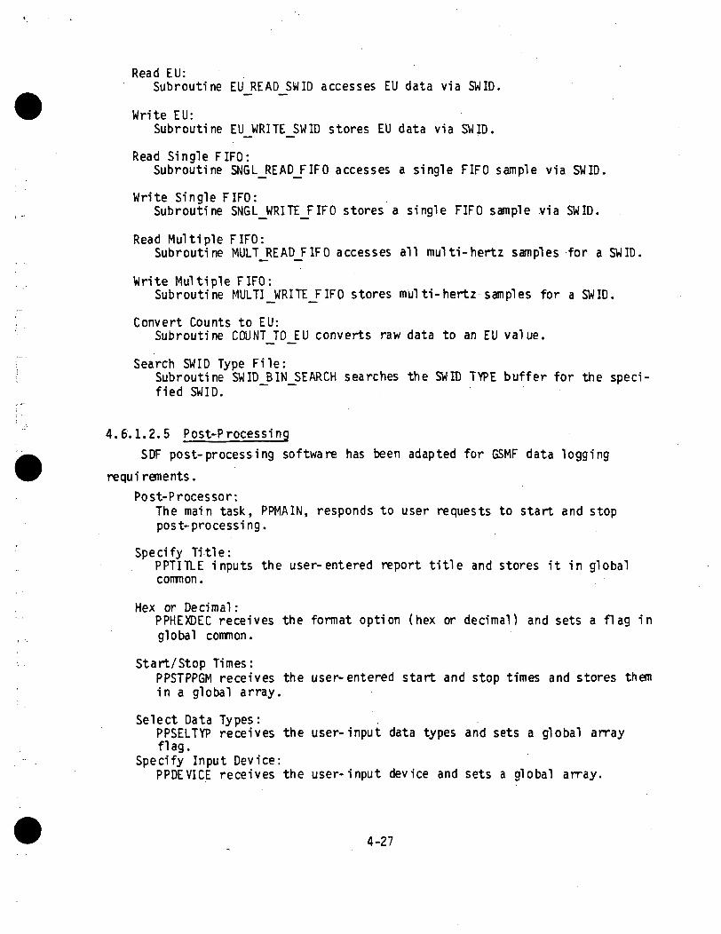
Read EU:Subroutine EU_READ_SWID accesses EU data via SWID.
Write EU:Subroutine EU_WRITE_SWID stores EU data via SWID.
Read Single FIFO:Subroutine SNGL_READ_FIFO accesses a single FIFO sample via SWID.
Write Single FIFO:Subroutine SNGL_WRITE_FIFO stores a single FIFO sample via SWID.
Read Mul t ip le FIFO:Subroutine MULT_READ_FIF0 accesses all multi-hertz samples for a SWID.
Write Multiple FIFO:Subroutine MULTI_WRITE_FIFO stores multi-hertz samples for a SWID.
Convert Counts to EU:Subroutine COUNT_TO_EU converts raw data to an EU value .
Search SWID Type Fi le :Subroutine SWID_BIN_SEARCH searches the SWID TYPE buf fe r for the speci-f ied SWID.
4.6.1.2.5 Post-Processing
SDF post-process ing software has been adapted for GSMF data logging
requirements.
Post-Processor:The ma in task, PPMAIN, responds to user requests to start and stoppost-processing.
Specify Title:PPTITLE inputs the user-entered report title and stores it in globalcommon.
Hex or Decimal :PPHEXDEC receives the format option (hex or decimal) and sets a flag inglobal common.
Start/Stop Times:PPSTPP6M receives the user-entered start and stop times and stores themin a global array.
Select Data Types:PPSELTYP receives the user-input data types and sets a global arrayflag.
Specify Input Device:PPDEVICE receives the user-input device and sets a global array.
4-27

Events Trail:PPEVT, utilizing the operator-selected output format, time periods,data types, and input device, generates the report.
4.6.1.2.6 Off-line File Build
The command file BLDOFFLN.CSS activates tasks to construct data files
used by simulation mode tasks. The offline tasks execute on terminal CRTS.Off-line File Builder:
BLDOFFLN executes off-line, independent of the GSMF host applicationsoftware. BLDOFFLN ouputs a menu permitting the user to build selectedGSMF host files.
Build Data Display File:BLDDSPFL allows the user to specify the SWIDs to be displayed by DataDisplay task.
Build Command Sequence File:BLDCMDSQ builds the command sequence file utilized by the CommandSequence task.
Build Initial Behavior Function File:The utility BLDINBEH allows the user to specify any Behavior Functionswhich are to be automatically activated upon selection of the simula-tion mode.
Read Setup Tape:The task RDSETUP copies the files created by the setup mode from tapeto disc.
Copy GC ID Fi 1 e to Di sk :GCIDZKSK transfers GCID application files from the VME port to the GSMFdi sk.
4.6.2 Link I nformation
All application tasks developed by TRW may be linked using the MODBLD
procedure (Section 4.6.1). This procedure requires the user to first create,
one time only, a command file X.CMD, where "X" is the task name. These com-mand files have already been created for all delivered tasks.
To build command files for additional tasks, the user shall edit fileTASKBLD.CMD. The " X X X X X X X X " fields shall be replaced with the task name, any
task-unique options added, and the file saved as X.CMD where "X" is the task
name.
4-28

Task-unique options consist of:
a) Resolving against GSMF library. After the "RESOLVE F7RTL51.RTL/S"statement, incl ude:"LIBRARY GSMF.LIB/G"
b) Resolving against global commons. If the task accesses global vari-ables, include one or more of the following statements:RESOLVE CMPOOL.TCM/S, ACC = RW, STRUCTURE * (CMPOOL/200)RESOLVE CCOM.TCM/S, ACC = RW, STRUCTURE = CCOMRESOLVE OPTNCOMB. IMG/G, ACCESS = RW RESOLVE DATACOMB. IMG/G, ACCESS= RWRESOLVE STATCOMB. IMG/3, ACCESS = RWRESOLVE BUFFCOMB. IMG/G, ACCESS = RWRESOLVE QUECOMB. IMG/G, ACCESS = RWRESOLVE DISCOFFS. IMG/G, ACCESS = RWRESOLVE LOOPWORK. IMG/G, ACCESS = RWRESOLVE TIMEWORK. IMG/G, ACCESS = RW.
Off-the-shelf software uses revision 6 libraries and must be TET'ed rather
than linked. The associated TET file for task "X" is called X.TET. To task-
build, enter "TET X", where "X" is the task name (DSPLYCTL, DLF, or LOGTOPRT).
4.6.3 Task Organization and Priority
4.6.3.1 Timing and Sizing
Table 4-4 summarizes response time estimates for GCID/ATE commands during
the simulation mode. Table 4-5 lists measured actual response time. These
times, measured with a 120 hertz clock, are accurate to 8.5 milli-second. Table 4-6 illustrates memory usage.
4.6.3.2 Task Priori tyTable 4-7 lists the priority requirements for the Simulation Mode tasks
and utility routines, where 1 is the highest priority and 255 is the lowest
priority.
4.6.4 Maintenance Function DescriptionAfter the GSMF simulation and related software are baselined and accepted
as an operational viable product, there are certain areas that must be ad-
dressed regarding software maintenance. These areas are described in the
following sections. Section 4.6.5 details the steps that shall be used to
make any changes to the baselined GSMF software.
4-29

Table 4-4. Timing Estimates (Standalone Mode)
A. Respond to MSE CommandsACTIVITY
1. RECINTER queue to MSESIM2. MSESIM processing3. MSESIM queue to BEHSCHED4. BEHSCHED processing5. BEHSCHED queue to behavior
function6. Behavior Function processing
TOTALS
B. Response to SCCD StatusACTIVITY
1. RECINTER queue to SCCDSIM2. SCCDSIM processing3. SCCDSIM queue to BEHSCHED4. BEHSCHED processing5. BEHSCHED queue to behavior
function6. Behavior Function processing7. Queue to SCCDCONC8. Concentration algorithm
TOTALS
C. Response to TLC CommandACTIVITY
1. RECINTER queue to TLCQHNDL2. TLCQHNDL processing3. Queue to ECOSSIM/SCOSSIM4. ECOSSIM/SCOSSIM response
TOTALS
D. Response to BSR InterruptACTIVITY
1. RECINTER queue to SCOSSIM/ECOSSIM
2. Update GMT and PIOL3. SCOSSIM/ECOSSIM queue to
GENINTERTOTALS
No Logging1 msec1 msec1 msec
1.5 msec
1 msec1 msec
6.5 msec
No Logg.ing1 msec1 msec1 msec
1.5 msec
1 msec1 msec1 msec10 msec17.5 msec
No Logging1 msec1 msec1 msec
0.5 msec3.b msec
No Logging
1 msec0.1 msec
1 msecZ.I msec
TIMELogging1 msec2 msec1 msec
2.5 msec
1 msec2 msec
8.5 msec
TIMELogging1 msec2 msec1 msec
2.5 msec
1 msec2 msec1 msec10 msec
20.5 msec
TIMELogging1 msec2 msec1 msec
0.5 msec4.b msec
TIMELogging
1 msec1.1 msec
1 msec3.1 msec
4-30

Table 4-5. Measured Response Times (No Logging)
ACTIVITY TIME
A. Respond to MSE Stimuli 0-9 msec
B. Respond to TLC Commands 0-9 msec
C. Respond to BSR Interrupt 0-9 msec
D. Respond to SCCD Command, includingstatus array concentration 25-34 msec
4-31
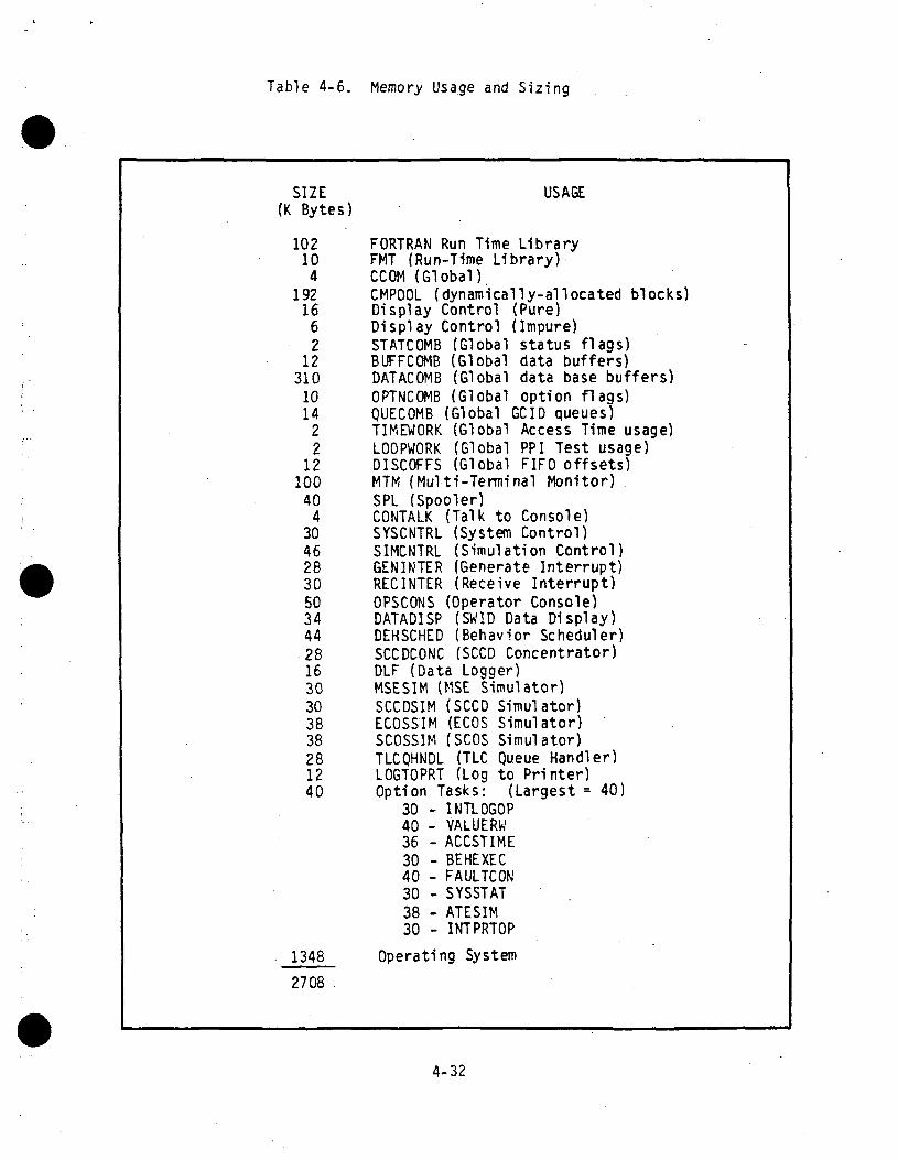
Table 4-6. Memory Usage and Sizing
SIZE(K Bytes)
102104
19216
62
12310
1014
22
12100
404
30462830503444281630303838281240
USAGE
FORTRAN Run Time LibraryFMT (Run-Time Library)CCOM (Global)CMPOOL (dynamically-allocated blocks)Display Control (Pure)Display Control (Impure)STATCOMB (Global status flags)BUFFCOMB (Global data buffers)DATACOMB (Global data base buffers)OPTNCOMB (Global option flags)QUECOMB (Global GCID queues)TIMEWORK (Global Access Time usage)LOOPWORK (Global PPI Test usage)DISCOFFS (Global FIFO offsets)MTM (Multi-Terminal Monitor)SPL (Spooler)CONTALK (Talk to Console)SYSCNTRL (System Control)SIMCNTRL (Simulation Control)GENINTER (Generate Interrupt)RECINTER (Receive Interrupt)OPSCONS (Operator Console)DATADISP (SWID Data Display)DEHSCHED (Behavior Scheduler)SCCDCONC (SCCD Concentrator)DLF (Data Logger)MSESIM (MSE Simulator)SCCDSIM (SCCD Simulator)ECOSSIM (ECOS Simulator)SCOSSIM (SCOS Simulator)TLCQHNDL (TLC Queue Handler)LOGTOPRT (Log to Printer)Option Tasks: (Largest = 40)
30 - INTLOGOP40 - VALUERW36 - ACCSTIME30 - BEHEXEC40 - FAULTCON30 - SYSSTAT38 - ATESIM30 - INTPRTOP
Operating System
4-32

Table 4-7. GSMF Host Task Priorities(1 = High, 255 = Low)
TASK PRIORITY
DLF (Data Logger) 30
DSPLYCTL (Display Control) 55
RECINTER (Receive Interrupt) 60GENINTER (Generate Interrupt) 60
TLCQHNDL (TLC Queue Handler) 65ECOSSIM (ECOS Simulator) 70SCOSSIM (SCOS Simulator) 70MSESIM (MSE Simulator) 72SCCDSIM (SCCD Simulator) 72
BEHSCHED (Behavior Scheduler) 75
SCCDCONC (SCCD Concentrator) 80
SYSCNTRL (System Control) 90
SIMINIT (Simulation Initialization) 90
DATALOAD (Load Data Base) 90
DOWNLOAD (Download to GCID) 90SIMCNTRL (Simulation Control) 95
LOGTOPRT (Log to Printer 115
OPSCONS (Operator Console) ' 125
DATADISP (SWID Data Display) 125
CMDSEQTK (Command Sequence Task) 125
4-33
4.6.4.1 Updated Operating System and FORTRAN VII Compiler
With the release of upgraded OS/32 operating systems and new releases forthe compiler, all routines shall be recompiled and relinked.
4.6.4.2 Space!ab Data Base UpdatesWith each new release of the Space!ab data base,the setup mode wi l l
generate the eight fi les that are to be used by the s imulat ion mode. Thesefiles are:
• SWID_MEASB_OFFSET FILE
• SWIDJYPEJABLE FILE
• STIMULI_SWID_OFFSET FILE
• SCOSJIFOJJFFSET F IL E
t ECOSJIFOJJFFSET FILE
• HARDWAREJJFFSET F I L E
• SWIDJNITIALJATA FILE
• RUN_DOCUMENTATION F I L E .
In the event that the SLDB is reconfigured, then the appropriate modi-fications shall to be made to the setup mode routines to reflect thesechanges.
4.6.4.3 Enhancements to KSC GSMF SystemIf any enhancements are made to the actual GSMF at KSC, then to ma in ta in
a true GSMF s imula t ion at MSFC, these same enhancements must be simulated asclosely as possible in order to ma in ta in the original f ideli ty.
4.6.5 Conf igura t ion Management Procedures
4.6.5.1 PurposeThe configuration management (CM) procedures describe the control mechan-
isms that shall be used dur ing the development of the GSMF. The GSMF softwarewi l l be controlled by the Integration Control Board ( I C B ) and the Software
4-34

Review Board (SRB) after sign-off. Experience has demonstrated that software
development efforts with a team of more than one developer is impeded by not
having a documented CM plan.
4.6.5.2 Scope
This plan describes the organization, responsibilities, policies, and
methods that shall be used in configuration management of the GSMF Computer
Program Components (CPC) during the development of the GSMF. After the GSMF
is accepted, the system shall follow the general policies and procedures of
the Spacelab Software Project. During integration the CM discipline applies
technical and administrative surveillance and control to the four principal
configuration areas: identification, control, status accounting, and review
and audits. These CM program elements are integral to the Configuration
Control Cycle described in Section 4.6.5.5.2. The CM program described in
this plan encompasses these four major areas through:
• Positive identification of all project software components, usingestablished reporting techniques, procedures, and policies.
t Rapid, comprehensive, and accurate treatment of proposed changes tothe GSMF software under configuration control to correct discrepan-cies, authorize deviation/waivers, and disseminate corrected documen-tation and software product changes.
• Detailed status accounting of all proposed, authorized, and imple-mented changes.
• Verification/audit of change control, including identification andstatus accounting of all descriptive documentation and projectmaterial s.
These objectives will be met by imposing this plan on all GSMF software
activities.
Section 4.6.5.3 discusses the application of the CM program to both the
deliverable and support software. Section 4.6.5.9 describes how the CM pro-
gram is applied to the software documentation.
4.6.5.3 Change Levels
There are two categories of changes to baselined software and documenta-
tion. Category 1 changes are those that impact other units or other documen-
tation or system performance. Category 2 changes are those with little or no
impact outside of the unit or documentation. Both Categories 1 and 2 changes
4-35

shall be approved through the configuration control cycle (Section 4.6.5.5.2).
However, for Category 2 changes, some of the steps (e.g., the analysis step)may be minimal or skipped with the approval of the software Lead Design Engi-
neer (IDE) Prior to baselining the software element or document, the indi-
vidual responsible for the element development is also responsible for main-
taining the element or document configuration. The formal configuration con-trol policies are applicable only after the software element or document isbaselined.
4.6.5.4 Configuration Management OrganizationThe Integration Control Board (ICB) has the primary responsibility for
the software configuration. The ICB is established to control and document
changes to baseline software and documentation. The ICB members are the GSMF
Project Lead Engineer, the LDE for software, and the software developer.
The LDE for software will be responsible for providing the ICB with the
information required to make effective decisions relative to proposed changesin the baselined software and documentation. The PDE will be assisted by a CM
custodian. The CM custodian will maintain logs of proposed and acceptedchanges to baselined software and documents. The developer is the only person
who can make changes directly to baselined software. The LDE will use otherGSMF development team members to provide analysis of proposed changes. The
LDE will determine the change category and verify that the change control
procedures are followed.
The Project Lead Engineer will be the ICB chairman. In this role theProject Lead Engineer will make the final determination on change approval or
rejection based on inputs provided by the PDE.Figure 4-6 is a graphic flowchart of the necessary steps taken when a
change is to be made to the baselined software.
4.6.5.5 Configuration Management Program Areas
As identified above, CM is divided into a number of interrelated areas.
These areas are configuration identification, configuration control, configu-
ration status accounting, and configuration review and audit. These CM pro-
gram areas apply to all baselined elements as described in Sections 4.6.5.3
and 4.6.5.4.
4-36

to.coo
intoOJuo
o
QJCD
to.co
to
QJs_
4-37ORIGINAL PmE !?sOF POOR QUALITY

4.6.5.5.1 Configuration I dentification
One of the primary functions of CM is configuration identification. Con-figuration Identification assures that the configuration of software products
is specified and controlled. Configuration identification will be applied tosoftware elements, documents, and test material. The original internal con-
figuration and all subsequent baselines of requirements documentation, designdocumentation, test documentation, and the physical software products areestablished. The configuration identification responsibilities are to:
• Establish identifiers for documents, software, and test materials
t Define configuration baseline items and periods of control for base-lines established for program
• Establish identifiers for initial as well as subsequent versions ofbaselined elements
• Define and support system to release software products and theirdocumentation into a controlled environment.
4.6.5.5.2 Configuration Control
The configuration control function ensures a staple environment and anorderly transition from one major commitment point (baseline) to the next. Abaseline is the configuration identification approval point from which allsubsequent changes require documentation, review, impact assessment, approval,and authorization prior to implementation. The GSMF ICB is the entity respon-sible for processing changes to the baselines. The change control procedure
for GSMF is described in detail in Section 4.6.5.6.1.A major function of CM is change control. This function ensures that all
proposed changes to the baselined products are both warranted and can accom-plish their intended purpose. Change control also ensures that only approvedchanges are incorporated into baselined elements.
4.6.5.5.3 Configuration Status AccountingThe Configuration Status Accounting provides records of initial releases,
changes, change request, and their dispositions for the software and relateddocumentation. Periodic status reports reflect the approved configuration aswell as the status of proposed and approved changes.
4-38

There shall be logs maintained of all Software Problem Reports (SPRs),
Engineering Change Proposals (ECPs) , and Software Release Notices (SRNs).
These logs will provide the official current status of problems and changes
that have been made or are being made to the baselined software.Listings of the baselined software elements and copies of the baselined
documents shall be maintained by'the CM custodian.Software sources, and object files shall be maintained in a directory
with only read and execute privileges of the baselined software. This direc-tory and its associated subdirectores will make up the current approved base-
line at any time. Changes to this directory can only be made by the respon-sible software developer with the ICB approval.
4.6.5.5.4 Configuration Review and Audits
Configuration Management will support all formal and project level inter-
nal reviews and audits until acceptance. The status accounting functionsshall be periodically audited to ensure that the current baseline and proposedchanges to the baseline are adequately identified. Documentation releases are
reviewed to ensure adherence to format requirements and release procedures.
The change control process shall be audited and reviewed to ensure that proper
procedures are followed and that the current baseline is identified and docu-
mented.
4.6.5.6 Configuration Control Cycle
When software elements are accepted for integration, they shall be base-lined and subject to the formal configuration control procedures described in
this document. In addition, when deliverable documents are finalized, theyshall be baselined and are also subject to the formal configuration control
procedures. The baseline version of the software elements and delivereddocuments may not be modified without proper documentation and approval. The
change control cycle shall be followed in making changes to accepted and base-
lined software and documents.
Change Control Procedures. The change control cycle for documentation and/or
software may be initiated by anyone on the project. This process is begun by
writing an SPR or an ECP. SPRs are written to describe errors or discrep-ancies in baselined software or documents. ECPs shall be written in response
4-39

to requirement changes or to propose improvements to baselined software or
document. Examples of sources for changes to baselined software or documents
are:
• Problem uncovered during integration and testing of software unit
• Change in GSMF software requirements
• Request from interfacing software unit designer
• Valid improvement in functioning of a program unit
• Problem developed by changing interfacing program unit.
Once an SPR or ECP is written, the CM custodian log the SPR or ECP for
recordkeeping and reporting purposes. The logged SPR or ECP will then be sentto the software LDE for evaluation.
If the LDE agrees that the SPR or ECP is valid, an SRN will be written.
The SRN is the formal document used to track the problem resolution or the
proposed enhancement through the change control cycle. However, if the LDE
disagrees with the SPR or ECP, they will discuss the disagreement with the
originator of the document. If the originator agrees with the LDE, the SPR or
ECP shall be closed and no SRN written. However, if the originator disagrees
with the LDE, the LDE will initiate a SRN. The LDE, as part of initiating theSRN, will assign developer(s) to evaluate the proposed change.
The LDE will send the SRN to the CM custodian for logging and to theselected developer! s) for further analysis. The developed s) will estimate
impacts to other software elements and documents. In addition, the develop-
er(s) shall estimate the time to effect the proposed change. The developer(s)
may suggest actions or alternatives to the proposed change. After the
developer!s) complete the analysis, the SRN will be updated and sent to the
ICB.The ICB will consider each open SRN on an as-needed basis. The ICB shall
review the SRN and determine what action to take. There are three actions that
the ICB can take:
t Accept SRN - LDE is then tasked with assigning responsibility andscheduling implementation and change
t Defer SRN - In cases where ICB thinks that more thought is neededbefore the SRN final disposition can be determined, or in the case ofan SRN which has a lower priority than others, the SRN may be deferreduntil a later meeting of the ICB
4-40

• Reject SRN - If the ICB decides that change is not justified, SRN willbe rejected.
In all cases, the IDE shall update the SRN with the board's action and
send the SRN to the CM custodian for update. Deferred SRNs will either return
to the ICB for reconsideration at a later date or be sent to developer(s) for
further analysis. Rejected SRNs shall be closed and a copy of the SRN with an
explanation of the reason for the rejection will be sent to the originator( s)
of the SPR(s) or E C P ( s ) . Accepted SRNs shall be returned to the LDE for
assignment to responsible developer(s) and/or analyst(s) to implement .the
changes.
After the changes are implemented (not in the baselined software or
documents, but in copies of the baseline versions), the LDE will review the
changes. If the changes are approved by the LDE, the documentation of the
changes and the test results shall be sent ot the ICB for approval. If the
LDE finds problems with the changes, the SRN shall be returned to the devel-
oper(s) for correction before passing the changes on to the ICB for approval.
If the ICB approves the changes and the documentation of the changes, the
SRN shall be sent to the CM custodian for inclusion in the baseline version
and SRN closeout. The custodian will then update the ECP or SPR and the SRN
indicating data and time of baseline update. The logs for the appropriate CM
documents will be updated. The ECP or SPR originator will be notified of the
changes and the process shall terminate for that change.
4.6.5.7 Configuration Control Forms
There are three forms that shall be used in configuration control: the
ECP, SPR and SRN. These forms can be obtained from the Configuration Manage-
ment Office, TRW, Building 4706.
4.6.5.7.1 Engineering Change Proposal (ECP)
The ECP shall be used to initiate changes to the baseline software and/or
documents that are not discrepancies or errors. The ECP can be initiated by
any project team member. Examples of sources of ECPs are:
• Change in requirements that require a change to baseline documents orsoftware
• Valid improvement in the functioning of a program unit.
4-41
The originator of the ECP shall complete an ECP with the following infor-
mati on:
t Originator - Originator's name
• Date - Current date
• Affected Software Name - Name of unit or routine
• Affected Software Version - Current baseline version number
• Affected Software File - Location of current baseline version
• Affected Documents Name - Name of affected document
• Affected Documents Control Number - TRW s document control number
• Related SPR - Any known outstanding SPRs that are related, by number
t Description of Change - Proposed change should be described in text(if more space is needed include continuation pages)
• Reason for Change - Textual description of advantages or reason forchange (if more space is needed include continuation pages).
After filing in the ECP, the originator shall deliver the ECP to the CM
custodian. The CM custodian will log the ECP in the ECP notebook assigning it
the next sequential ECP number. The CM custodian shall make a copy of the ECPand put the original in the ECP notebook. The CM custodian shall deliver the
logged ECP to the IDE.
The IDE will review the ECP and determine preliminary disposition. If
the IDE agrees with the proposal, he will use the information from the ECP to
initiate a SRN. If the IDE disagrees with the proposal, the LDe will discuss
the proposal with the initiator. If the originator agrees that the proposed
change is not needed, the CM custodian will close the ECP and the process
stops. If the originator does not agree that the proposed change is unneeded,
the LDE will initiate a SRN for the ECP.
The ECP log book shall be available for review to all project members.
In addition, the CM custodian shall prepare a report of all open ECP's for
distribution to all project members.
4-42

4.6.5.7.2 Software Problem Report (SPR)
The SPR shall be used to initiate changes to the baseline software and/or
documents due to discrepancies or errors. The SPR can be initiated by any
project team member. Examples of sources of SPRs are:
t Problem encountered during integration testing of software unit
• Problem encountered during testing of interfacing software unit
• Problem with documentation during any of software development phase.
The originator of the SPR must complete an SPR with the following infor-
mation:
• Originator - Originator's name.
• Date - Current date.
• Affected Software name - Name of unit or routine.
• Affected Software Version - Current baseline version number.
• Affected Software File - Location of current baseline version.
• Affected Documents Name - Name of affected document.
• Affected Documents Control Number- TRW s document control number.i
• Discovery source - Source of problem discovered during one of thefollowing phases: REVIEW, UNIT TEST, INTEGRATION AND TEST,ACCEPTANCE, OPERATION, or OTHER.
• Related SPR - Number of known outstanding SPRs that are related.
• Problem Description - First describe whether symptoms are repeatableand if problem documentation is included. Textual description ofproblem encountered should then be written. Continuation pages shouldbe included if needed to adequately describe problem. If problem isreadily repeatable, a description of how to repeat the problem shouldbe included in this section.
• Suspected Cause - If originator has an idea of suspected cause of theproblem, it is entered here. Continuation pages are included ifneeded. If more than one thing may have caused the problem, origi-nator should include each possible cause here.
• Recommended Fix - If originator has suggestion on how problem can befixed, that suggestion is documented in this section. If continuationpages are needed, include them.
4-43

After filling in the SPR, the originator shall deliver the SPR to the CM
custodian. The CM custodian will log the SPR in the SPR notebook and assign
it the next sequential SPR number. The CM custodian will make a copy of the
SPR and put the original in the SPR notebook. The CM custodian will deliver
the logged SPR to the IDE.
The IDE will review the SPR and determine preliminary disposition. If
the IDE agrees that a problem exists, the LDE shall use the information from
the SPR to initiate a SRN. If the LDE disagrees that a problem exists, he
will discuss the proposal with the originator. If the originator agrees with
the analysis of the LDE, the SPR shall be closed by the CM custodian and the
process stops. If the originator does not agree with the LDE's analysis, the
LDE shall initiate a SRN for the SPR.
The SPR log book will be available for review to all project members. In
addition, the CM custodian shall prepare a weekly SPR report for distribution
to all project members.
4.6.5.7.3 Software Release Notice (SRN)
An SRN will be initiated by the LDE in response to either an SPR or an
ECP. The LDE shall initiate the SRN by filling in the following sections on an
SRN form:
t Date - Current date.
• Associated SPR(s) - Originating SPR(s) is identified by number.Related SPRs and ECPs may be included on one SRN.
t Associated ECP(s) - Originating ECP(s) is identified by number(related SPRs and ECPs may be included on one SRN).
t Affected Software - Same software described on SPR or ECP; however, ifLDE suspects that other software elements are affected, these are alsoincluded.
t Affected Documents - Same documents described on SPR or ECP; however,if LDE suspects that other documents are affected these are alsoincluded.
After entering the above information, the SRN will be sent to the CM
custodian for the assignment of the next sequential SRN number and for logging
into the SRN notebook. A copy of the SRN shallbe included in the SRN notebook
4-44

and a copy returned to the LDE. The IDE will then assign a developer! s) to
analyze the problem and provide them with a SRN copy and the originating
document! s).
The analysis must include time estimates and potential impacts on other
software elements or documents. The analysis shall also provide for recommen-
ded changes or recommend that the SRN be rejected for cause. The analyzed
SRN(s) will be sent to the CCB for a decision of final disposition.
The CCB shall review the analyzed SRN(s) and determine what action to
take. There are three courses of action possible by the CCB: (1) reject
proposed change; (2) defer change or decision on change; or (3) accept pro-
posed change. In all cases, the indicated action shall be entered on the SRN
and the status of the SRN log updated by the CM custodian.
If the proposed change is rejected, the SRN and the supporting SPR(s) or
ECP(s) shall be closed and the originator will be notified of the reason for
the rejection. The process on rejected and closed SRN(s) is complete at this
stage.
If the proposed change is deferred, there are two possible paths for the
SRN. If the deferral is for further analysis, the LDE shall assign responsi-
bility and direction for that analysis. If the deferral is due to lack of
resources to pursue the change at this point, the LDE shall schedule the
reconsideration of the SRN at a later CCB meeting.
If the proposed change is to accept the SRN, the LDE shall assign a
developer! s) or analyst! s) the task of implementing the change. The change
shall be made not on the baseline software or documents, but on the copies of
the baselined elements. After the change is completed, the LDE will approve
the changes and provide the CCB with documentation supporting the changes.
After approval of all changes, the SRN shall be marked as completed and
sent to the CM custodian. After the custodian makes the approved changes in
the baselined elements, the SRN and its associated ECP(s) or SPR(s) will be
closed. The originator! s) of ECP(s) or SPR(s) which initiated the SRN shall
be informed of the completion of the changes suggested and the process will be
terminated.
4-45
4.6.5.8 Software Configuration Control
The software elements that are under configuration control are both theGSMF software and the tools used in testing and development. The procedures
for configuration control described in Section 4.6.5.6 shall be applicable toall software elements when they are accepted for integration. Changes tothese elements, once accepted, shall be controlled and the current configu-ration maintained under the ICB authority and not the individual developers.
4.6.5.8.1 GSMF Software
The GSMF software units, as defined in the Compute Program Product Speci-fication, are considered baselined when they are accepted for integration.
This means that problems encountered prior to acceptance for integration withthe software are not the responsibility of the ICB, but are the responsibility
of the developer of the affected software unit. After acceptance for integra-tion, however, the procedure for CM including identification, control, status
accounting, and review and audits shall be followed for any changes. Thedeveloper, however, shall be responsible for maintaining development and testrecords of sufficient quality to provide a basis for audit, and acceptance ofthe software unit for integration. This includes traceability of the softwareunit test results to the exact version of the software offered for baselining.
4.6.5.8.1.1 Configuration Identification
Each structural entity of the real-time deliverable software from thefunction level to the lowest level that can be included in the source libraryshall be identified with a software identification number. Software compo-nents, including common blocks, will be uniquely identified at the lowestidentifiable level.
Routines and common blocks will be identified by the appropriate unitname concatenated with the routine or common block name. Names of GSMF rou-tines and common blocks are available in the GSMF Detailed Design document.
Support software tools shall be identified by their name and a sequential
version number as is done with the real-time software.
4-46

4.6.5.8.1.2 Configuration Control »
The GSMF real-time software is applicable to configuration control.
After units of GSMF are accepted for integration, the formal control mechan-
isms described in Section 4 .6 .5 shall be applied to proposed changes to thesoftware units. Prior to acceptance for integration, normal development
procedures will be applicable for required changes. Software control at thisstage is through DDF review and design and code walkthroughs.
When the GSMF is completed and accepted by NASA, the CM responsibilitiesof TRW for that software will continue.
4.6.5.8.2 Support Software Tools
The software used to support the development and the test of the GSMF
software shall be subject to configuration control procedures. This software
includes the executable tools developed specifically for GSMF, existing sup-port libraries, data files, and command procedures used for execution and
testing. Perkin Elmer or other outside vendor software, will not be under theGSMF configuration control procedures. Examples of software not under con-
figuration control of GSMF are the OS/32 operating system, the FORTRAN VII
compilers, and other support tools not developed by TRW. Test drivers and
stubs developed only to support unit level testing will not be included in theconfigurable software set.
GSMF Specific Software Tools. There are two interrelated software tools that
support the testing of the GSMF software: data logging and the data reduction
tools. Once these tools are checked out and accepted in the baseline, changes
must be approved by the same procedures used to modify baselined GSMF code.The source, object, and executable code of these tools shall be con-
trolled in the same manner as the real-time deliverable software is con-
trolled. The procedures outlined in Section 4.6.5 shall apply to the proposed
changes in this code.
4.6.5.9 Document Control
The GSMF deliverable documentation shall under configuration control.
Once a final copy of any contract deliverable document is signed off by TRW
management for delivery to MDTSCO, that document is established as baselined.
4-47

Subsequent changes to the document shall be handled via the configuration con-
trol proceduers described in Section 4.6.5. Prior to baselining a document,
new revisions to the document shall be handled in the same manner as the
initial release. There is a signature procedure that must be followed the
same as for all TRW formal documentation.
Once baselined, changes to documents shall be done by publishing change
pages and instructions. If there are numerous changes to a baselined document
a new version can be published, if approved by the ICB.
Documents that are not contract deliverables such as this Configuration
Management Plan and the developer's Manual will not be under the control of
formal configuration management procedures. These documents, however, will be
under the normal TRW procedures for document publication and maintenance.
4.6.5.9.1 Document Identification
Each specification and related document shall be assigned a unique iden-
tificaiton number. This identification and numbering procedure will be appli-
cable to configuration identificaton documents and to all SDRLs. The identi-
fication number shall use the unique document control number generated by TRW
publications.
4.6.5.9.2 Deliverable Documentation
The deliverable documents that shall under configuration control are:
t GSMF Acceptance Test Plan
• GSMF Software Requirements
• GSMF Detailed Design
• GSMF User1 s Manual
• GSMF System Manual.
4.6.6 GCID Software Description
The GCID software for the standalone diagnostics will be resident in
executable form in read only memory installed on the GCID. Therefore the host
computer will not contain any feils to download either diagnostic.
4-48

The simulation software will be downloaded by the host computer before
execution. This software will be contained in five files on the Perkin-Elmerdisk with the following names:
• TLMOPSW.DAT
• MSEOPSW.DAT
• TLCOPSW.DAT
t SCCDOPSW.DAT
• TIMEOPSW.DAT.
Each record of these files will contain one variable length Motorola
S-record. The file will be in source file format because Motorola S-recordsare actually an ASCII representation of the hex load data.
4.6.7 Setup Mode Data Base File
The following sections summarize the data base files built during theSetup mode and loaded during Simulation Initialization. All files are definedin Appendix C of the GSMF Software Design Document.
4.6.7.1 SWID Measurement Offset File
The file SWIDMEAS.DAT allows mapping into the host measurement buffer for
all SCCD/MSE SWIDs. The file contains records whose fields define the SWIDattributes necessary for measurement/stimul i processing.
4.6.7.2 SWID Type Table File
The file SWIDTYPE.DAT contains records whose fields define SWID, type,and offset. The offset is a pointer into the appropriate offset buffer.
4.6.7.3 Stimuli SWID Offset File
The file STIMSOFF.DAT relates stimuli to associated measurements andbehavior function. The file defines all affected measurements and indicatesthe behavior function for each stimuli.
4-49

4.6.7.4 SCOS FIFO Offset File
The file SCOSFIFO.DAT maps all SCOS telemetry data contained in the FIFO.
The file defines the location of each multi-hertz sample for each SCOS SWIWD.
4.6.7.5 ECOS FIFO Offset File
The file ECOSFIFO.DAT is functionally identical to the SCOS FIFO Offset
file.
4.6.7.6 Hardware Offset File
The file HARDWADD.DAT maps hardware addresses to stimuli SWIDs. The file
contains a pointer to the SWIDs entry in the Stimuli Offset file for each
hardware address.
4.6.7.7 SWID In i t i a l Data F i l eThe file SWIDINIT.DAT defines initial values to be assigned to measure-
ment SWIDs.
4.6.7.8 Run Documentation Data File
The file RUNDOC.DAT contains configuration data concerning the Setup mode
data base files.
4.6.8 Offline-Built Files
These types of data files are built offline on the GSMF. These files are
defined in Appendix D of the GSMF Software Design document.
4.6.8.1 Initial Behavior Name File
The file INBEHNM.DAT defines the user-written behavior functions to be
automatically activated during the simulation mode.
4.6.8.2 Command Sequence File
The file CMDSEQ.DAT contains the event criteria and actions to be taken
by the Coimand Sequence task. The file defines the criteria (either time or
measurement SWID) and the SWID and value to be output when the criteria is
satisfied for each event.
4-50

4.6.8.3 SWID Data Display Files
The SWID Data Display files are named by the user at creation. Each file
defines up to 16 Measurement SWIDs to be displayed and dynamically updated
once per second.
4.7 BEHAVIOR FUNCTIONS
Behavior functions execute either on manual command or in response to
stimuli received from the GCID. The relationship between stimuli, affected
measurements, and behavior function names is defined in the SWID Pairs file,
an input to the Setup mode. Two types of behavior functions are supported:
generic subroutines and user-written tasks.
Generic subroutines support the straightforward relationship identified
in the SL-3 data base. These subroutines are SOCDBF, DUALBF, DOSMBF, DORMBF,
GOMSBF, DOPANBF, DIGANALG, AOSABF, andGOCLBF. BEHSCHEDwill call the flagged
subroutine to simulate the effect for each measurement affected by a given
stimuli.
User-written tasks should be included in the Initial Behavior Name file
so that SIMCNTRL will activate them on mode startup. The Behavior Scheduler
will queue a packet defining the stimuli and hardware command. The user-
written task should deque and decode the packet, perform the simulation, de-
allocate the Compool block, and reenter trap wait. User-written behavior tasks
reside in account 114.
4.7.1 Modifications to Generic Functions
The generic subroutines reside in account 103. Some generic function
subroutines are tabledriven. The internal tables define the expected output
for each stimuli. To add other stimuli,
1) Edit the source file internal tables to include new stimuli and effect
2) Recompile subroutine by entering: MODBLD X, LINK = NO(X is subroutine name)
3) Relink Behavior Scheduler by entering:MODBLD BEASCHED, COMP = NO
4) Rename BEHSCHED.TSK from account 103 to system account.
4-51
4.7.2 Incorporating User-written Tasks
As previously defined, the user-written tasks should expect to receivequeue entries containing the following:
WORD FORMAT CONTENT
1 1*4 Stimuli SWID
2 1*4 Command Word 1
3 1*4 Command Word 2
4 1*4 Space
Table 4-8 illustrates the task framework. The task should enable queue en-tries to trap to a user subroutine. This subroutine should receive the block,simulate the effect, de-allocate the block, and reenter trap wait.
Account 114 was set up to hold the source and object files for user-written behavior tasks. To compile and build the task, the user should util-ize the MOOBLD.CSS procedure defined in Section 4.6.1.1 and rename the task tothe system account.
The task should be included in the Initial Behavior Name file to beinitially activated. This file is built offline as described in Section4.6.1.2.6.
4-52

Table 4-8. User-Written Behavior Task Framework
PROGRAM USERTASK
EXTERNAL QUETRAP
C
C
C
SET-UP TO RECEIVE QUEUE ENTRIES
CALL INIT
CALL ENABLE(2,QUETRAP)
CALL ENABLE(0)
END
INIT QUEUE STRUCTURE
QUEUES CAUSE TRAPS
INFINITE TRAP WAIT
SUBROUTINE QUETRAP (IADR)
C THIS SUBROUTINE EXECUTES AT TRAP LEVEL UPON RECEIPT
C OF A QUEUE ENTRY. IADR IS THE ADDRESS OF THE 4-WORD
C PACKET FROM BEHSCHED.
CALL OPMSGRC (...) ; RECEIVE COMPOOL BLOCK
PERFORM SIMULATION
CALL OPMSGRR (IADR)
RETURN
END
; DEALLOCATE BLOCK
; BACK TO TRAP-WAIT
4-53

5. FAULT ISOLATION
5.1 GCID HARDWARE
The GCID DIAGNOSTICS provides control of a series of specific tests tosupport troubleshooting and GCID hardware maintenance. The following tests
with functional verification shall be performed:t GLOBAL RAM
t VME RAM
t DMA
• INTERRUPT GENERATION.
5.2 PE-TEST MODE
The PE TESTs are vendor-supplied diagnostics software that are provided
to control a series of tests to support the PE hardware maintenance. Thefollowing tests will be performed:
t KEYBOARD
t TAPE
• DISPLAY
• DISK
• VMEBI
t PPI.
5.3 PPI LOOP BACK TEST
The SDF PPI interface function includes a loop-back capability. Option 4of the initial GSMF menu, allows the user to exercise this capability. The
PPI Test function allows the user to send configurable patterns to either SDFfor a specified number of repetitions.
5.4 ITTS SOFTWARE
The MITRA-resident ITTS software allows for testing of the ATE-GCID,hardware interface, GCID-GSMF hardware interface, GCID simulation software,
and GSMF simulation software on a step-by-step basis. Each ATE functionalcapability (i.e., TLC command, SCCD command, etc.) may be exercised on a
single-shot basis. -

5.5 VALIDATION SOFTWARE
The MITRA-resident Validation software allows the user to execute pre-
constructed test sequences to verify operation of the ATE functional capa-
bilities.
5.6 SIMULATION MODE PERFORMANCE MONITOR
A Performance Monitor was developed to troubleshoot GSMF simulation mode
problems. This package allows an analyst to dynamically view CCMPOOL usage,
queue usage, SCCD summary status, TLC response, GCID processor status, FIFO
buffer contents, and GCID-maintained MET and GMT.
5-2