Embed Size (px)
Citation preview

BERMUDA BRIDGES
Specification for Ground Investigation
for
Government of Bermuda – Ministry of Public Works
January 2018
Project no. 1620003502 Report no. 1620003502/CG/SP/01
Ramboll UK Carlton House
Ringwood Road Woodlands
Southampton SO40 7HT United Kingdom
tel 023 8081 7500 fax 023 8081 7600

Report No. 1620003502/CG/SP/01 Specification for Ground Investigation
1620003502-CG-SP-01.docx Rev: 2
Revision History
Revision Date Purpose / Status Document Ref. Comments
2 16.01.18 For Tender 1620003502/CG/SP/01
1 20.12.17 For Tender 1620003502/CG/SP/01
0 08.12.17 Draft for Client comment
1620003502/CG/SP/01
Prepared By Reviewed By Approved By
Manuel Garcia Ian Lewis Andy Rose
Graduate Engineer Principal Engineer Project Director
Ramboll Carlton House Ringwood Road Woodlands Southampton SO40 7HT United Kingdom tel +44 (0)23 8081 7500 fax +44 (0)23 8081 7600 [email protected]

Report No. 1620003502/CG/SP/01 Specification for Ground Investigation
1620003502-CG-SP-01.docx Rev: 2
CONTENTS Section Item Page 1 SPECIFICATION 1
SCHEDULE 1 INFORMATION 1 SCHEDULE 2 EXPLORATORY HOLES 19 SCHEDULE 3 INVESTIGATION SUPERVISOR’S FACILITIES 20 SCHEDULE 4 SPECIFICATION AMENDMENTS 21 SCHEDULE 5 SPECIFICATION ADDITIONS 22
ANNEX 1: BILL OF QUANTITIES FOR GROUND INVESTIGATION 24 ANNEX 2: STANDARDS FOR GROUND INVESTIGATION (ASTM) 33 ANNEX 3: INFORMATION FOR DAILY RECORDS 42 ANNEX 4: INFORMATION FOR EXPLORATORY HOLE LOGS 43 Figures Figure 1 SITE LOCATION PLAN Figure 2 ENVIRONMENTAL AND PLANNING CONSTRAINTS LONGBIRD BRIDGE Figure 3 ENVIRONMENTAL AND PLANNING CONSTRAINTS SWING BRIDGE Figure 4 LONGBIRD BRIDGE EXPLORATORY HOLE LOCATION PLAN Figure 5 SWING BRIDGE EXPLORATORY HOLE LOCATION PLAN Appendices APPENDIX A RATES FOR GROUND PRACTITIONERS AND OTHER PERSONNEL APPENDIX B LONG-TERM SAMPLE STORAGE APPENDIX C CHEMICAL TESTING SUITES
Report No. 1620003502/CG/SP/01 Specification for Ground Investigation
1620003502-CG-SP-01.docx Rev: 2 Page 1
1 SPECIFICATION
Specification This document constitutes the Specification for the Ground Investigation and shall be read in accordance with the UK Specification for Ground Investigation the standards published by American Society for Testing and Materials (ASTM), with information, amendments and additions as described in the Schedules:
Schedule 1. Information and site-specific requirements Schedule 2. Exploratory holes Schedule 3. Investigation Supervisor’s facilities Schedule 4. Specification amendments Schedule 5. Specification additions
Additional Terms of Reference are listed in Schedule 5.1
Schedule 1 Information
S1.1 Name of Contract
Bermuda Bridges
S1.2 Investigation Supervisor
Ian Lewis of Ramboll, Carlton House, Ringwood Road, Woodlands, Southampton, SO40 7HT, United Kingdom The Conditions of Contract shall be the Infrastructure Conditions of Contract Ground Investigation Version dated August 2011. For the purposes of this specification, the “Ground Specialist” as defined in the Conditions of Contract shall be the Investigation Supervisor.
S1.3 Description of Site
The site is located in Bermuda Islands, in the north-western Atlantic Ocean. There are two different locations for the investigation: Longbird Bridge (link between St. Davis’s Island and Bermuda Island) and Swing Bridge (link between St. David’s Island and St. George Island). The exploratory holes are located close to those structures.
S1.4 Main Works Proposed and Purpose of this Contract
It is proposed to construct a new bridge parallel to Swing Bridge on its northeast side and to replace Longbird Bridge structure. It is assumed that the works at Bermuda bridges consist of:
• Longbird Bridge: - Demolition of the old bridge (abutments included) - Construction of a new bridge in the same location - Construction of the connections between the new bridges
and the existing roads. • Swing Bridge:
- Construction of a new bridge on the northeast side of the existing bridge
Report No. 1620003502/CG/SP/01 Specification for Ground Investigation
1620003502-CG-SP-01.docx Rev: 2 Page 2
- Construction of the connections between the new bridge and the existing roads
- Associated infrastructure This investigation shall constitute the main investigation and the findings are to be used during the design and construction of the new bridges.
S1.5 Scope of Investigation
The investigation shall comprise: • Nine rotary boreholes. • In-situ testing and sampling. • Hand dug inspection pits for boreholes. (Only on land) • Five machine excavated trial pits. • Geotechnical laboratory testing. • Contamination laboratory testing.
The exploratory hole details are summarised in Schedule 2. S1.6 Geology and Ground Conditions
A general scope shows that the geology of the Bermuda area comprises a sequence of aeolian and marine sediments of coralline (calcium carbonate) origin. The basal geology of the Bermuda Seamount is a sequence of volcanic basaltic lava, pyroclastic and intrusive flows. The upper sediments are known to have been subjected to a varying amount of weathering. This includes cementation and the formation of voids. Due to the construction of L.F. Wade International Airport within St. David’s Island, it was necessary to level and link several smaller islands to create enough space for the airport itself. The dredged fill to infill between them consisted of coralline deposits and/or limestone sediments (composed of marine skeletal remains, gravel and sand-size fragments). The depth of the reclaimed fill varies between 3 metres and 10 metres. The general ground profile shows a stratigraphic sequence of fill/made ground, followed by coralline deposits with several grades of cementation and a Basalt bedrock.
S1.7 Schedule of drawing(s) and documents
The following drawings and documents are provided:
Title Reference Notes
Site Location Plan Figure 1 Exploratory Hole Location Plan Figure 4 and Figure 5
Any available service/utility drawings will provided prior to the investigation commencing.
S1.8 General Requirements - Particular Restrictions / Relaxations
Contract specific details, are detailed in the following schedules. The work on site shall not commence until the Employer is satisfied that a suitable and sufficient Health and Safety Plan, complying with the current Regulations, has been produced for the works.

Report No. 1620003502/CG/SP/01 Specification for Ground Investigation
1620003502-CG-SP-01.docx Rev: 2 Page 3
S1.8.1 Quality management system
Quality management to ISO 9001:2015, ISO 14001:2015 and OHSAS 18001:2007 is required.
S1.8.2 Professional attendance
Professional Attendance shall be provided by the Contractor in the form of the provision of technical staff as necessary to fulfil the technical, logistical and quality requirements of the works. Proposed personnel shall be suitably qualified, with at least three years’ experience. The Contractor’s tender shall provide CV’s and detail the number, names and experience details of the proposed staff and the times which each member of staff is anticipated to spend at the site. Bill of Quantities Item A7 shall be used to detail the Contractor’s expected Professional Attendance.
S1.8.3 Provision of ground practitioners and other personnel
Drilling and site staff qualifications shall be provided within the Tender Return. The Contractor is to prepare the specified factual part of the Ground Investigation Report. The Contractor’s expected staff times for report compilation, preparation and checking are to be included in Bill of Quantities Item A7. The Contractor is required to complete the table of rates include in Appendix A.
S1.8.4 Hazardous ground, land affected by contamination and notifiable and invasive weeds
None known of on site.
S1.8.5 Additional information on services not shown on Contract drawings
Available service information will be provided prior to intrusive works on site. Local services and service connections may also be present at the site.
S1.8.6 Known suspected mine workings, mineral extractions, etc.
None known.
S1.8.7 Protected species None known.
S1.8.8 Archaeological remains
None known.
S1.8.9 Security of site Where possible all exploratory hole positions shall be fenced off and made secure during the works. Besides, all barriers breached or otherwise disturbed during the execution of site operations shall be immediately repaired or replaced to the same standard.
S1.8.10 Traffic management measures
Access and egress routes through the work site shall be agreed with the Client prior to commencing the site works.
S1.8.11 Restricted working hours
Site working hours shall be 0800hrs to 1800hrs Monday to Friday. Weekend working shall be at
Report No. 1620003502/CG/SP/01 Specification for Ground Investigation
1620003502-CG-SP-01.docx Rev: 2 Page 4
the discretion of the Engineer. Working hours outside of those stated shall be agreed with the Client.
S1.8.12 Trainee site operatives
Site operatives shall provide qualification, appropriate to their status to the type of work being undertaken.
S1.8.13 Contamination avoidance and/or aquifer protection measures required
Not anticipated. If any signs (visual and/or olfactory) of significant contamination are encountered, particularly Non-Aqueous Phase Liquid (NAPL), the Contractor shall inform the Engineer immediately. The Contractor shall allow for provision and use of protection/bunding of equipment and plant such that spillages and pollution of the ground from fuel and oil does not occur.
S1.8.14 Maximum period for boring, pitting or trenching through hard material, hard stratum or obstruction
The terms “hard stratum”, “hard material” and “obstruction” shall mean natural or artificial material, including rock, which cannot be penetrated except by the use of hard boring techniques (chisel/shell with additional weights, etc.) during cable percussion boring, rotary drilling, blasting or powered breaking tools. The terms “hard stratum,” and “obstruction” shall apply to percussive boring, only where it is shown that condition (a) and either condition (b) or condition (c) below are fulfilled, provided that the boring rig involved is in good working order and is fully manned. The progress rate observations and driving tests shall be repeated at hourly and 0.50 m depth intervals, respectively. Condition (a).- Boring with normal appropriate tools cannot proceed at a rate greater than 0.50 m/hour. The stated rate shall be applicable to the boring operation alone and exclude sampling/in situ testing and standing time. Condition (b).- 100 mm diameter undisturbed sample tubes cannot be driven more than 300 mm with 50 blows of the driven hammer. Condition (c).- A Standard Penetration Test (SPT) shows a resistance in excess of blows/75 mm. The term “hard material” shall apply only to machine excavation of trial pits and trenches and observation pits and trenches where it is shown that condition (d) or (e) below are fulfilled. Condition (d).- Natural or artificial material, including rock, is encountered in masses exceeding 0.20 cubic metres which cannot be penetrated except by the use of powered breaking tools. Condition (e).- Existing pavements, footways, paved areas (but excluding unbound materials) and foundations in masses exceeding 0.20 cubic

Report No. 1620003502/CG/SP/01 Specification for Ground Investigation
1620003502-CG-SP-01.docx Rev: 2 Page 5
metres which cannot be penetrated except by the use of powered breaking tools. The term “hard material” shall apply only to hand excavation of inspection pits and observation pits and trenches where it is shown that conditions (f) and (g) below are fulfilled. Condition (f).- Natural or artificial material, including rock, is encountered in masses exceeding 50 kg which cannot be penetrated except by the use of powered breaking tools. Condition (g).- Existing pavements, footways, paved areas (including unbound fill materials) and foundations in masses exceeding 50 kg which cannot be penetrated except by the use of powered breaking tools. If unexpected or hard ground conditions (above those already anticipated) are encountered then the Investigation Supervisor shall be informed, who may instruct the use of one or more of the following: 1) Continuation of appropriate techniques. 2) Rotary or other approved drilling until the
stratum is proved for a sufficient depth (should the hard stratum prove to be a thin layer and further boring be required beneath, the Contractor shall break it out sufficiently to enable boring, in situ testing and sampling to proceed).
3) Abandonment of the borehole and a further borehole started nearby to obtain the required samples and/or in situ tests.
The progress rate observations and driving tests necessary to demonstrate that a “hard stratum” or “obstruction” has been encountered shall be included on the daily record.
S1.8.15 Reinstatement requirements
Operations shall be confined to the minimum area of ground required for the safe execution of the Works. On completion of each exploratory hole all equipment, surplus material and rubbish of every kind shall be cleared away. Surplus material and rubbish shall be removed from the site to a disposal point licensed to accept the waste concerned. The whole of the site and any ancillary shall be left in a clean and tidy condition. In case the Works take place on paved areas, it shall be broken out to the minimum extent necessary for each exploratory hole. After completion of the hole the paved area shall be reinstated.
S1.8.16 Hygiene facilities As specified in the current Health and Safety

Report No. 1620003502/CG/SP/01 Specification for Ground Investigation
1620003502-CG-SP-01.docx Rev: 2 Page 6
required regulations, as well as the Health and Safety plan proposed for the works.
S1.8.17 Unavoidable damage to be reinstated by Contractor
Not anticipated.
S1.8.18 Accuracy of exploratory hole locations
Each exploratory hole shall be set out at the location given to the nearest 1 metre. During the period of the site operations, the elevation of the ground at each as-built exploratory hole related to Ordnance Datum shall be established to the nearest 0.05 metres.
S1.8.19 Photography requirements
Photographs shall be taken as follows: • Exploratory hole location prior to
commencement of works • Exploratory hole location following
completion of works • Rotary core samples • Pit or trench photographs
S1.8.20 Notice to the Investigation Supervisor
The Investigation Supervisor shall be given at least 7 days notice of the commencement of work on site, and 2 hours notice of movement between exploratory hole positions. The Contractor shall inform the Investigation Supervisor of each and every instance where standing time exceeds 30 minutes.
S1.8.21 Sensitive Habitat areas
Several areas of sensitive habitat are located within and close to the site boundary. These are shown in Figures 2 and 3.
S1.8.22 Working Procedures The Contractor must adhere to the local rules and regulations regarding working on-shore and off-shore locations.
S1.8.23 Ground Protection at Exploratory Hole Positions
Ground within each of the working areas shall be protected with boards/sheeting. Drilling rigs shall work from hardstanding areas only. All work areas to be fenced and also with protective sheeting applied.
S1.9 Percussive Boring - Particular Restrictions / Relaxations
Contract requirements, are detailed in the following schedules.
S1.9.1 Permitted methods and restrictions
The works shall be undertaken under ASTM standards. Should the Contractor wish to commence drilling using cable percussive drilling they shall be responsible for selecting the appropriate casing at the start of boring/drilling to account for any necessary reduction in casing size to achieve the minimum diameter required at the base of the borehole. Necessary precautions shall be taken to prevent fuel spillage entering the ground or
Report No. 1620003502/CG/SP/01 Specification for Ground Investigation
1620003502-CG-SP-01.docx Rev: 2 Page 7
groundwater. Whenever water is added to the borehole, the depth at which it is added together with the volume added shall be recorded on the driller’s daily logs. Only the minimum amount of clean water shall be added to the boreholes to aid boring.
S1.9.2 Backfilling Boreholes not requiring monitoring piezometers/ standpipes to be installed shall be backfilled with arisings (see item S1.8.15) or grout as directed by the Investigation Supervisor.
S1.9.3 Dynamic sampling Not required.
S1.10 Rotary Drilling - Particular Restrictions / Relaxations
Contract specific requirements, are detailed in the following schedules.
S1.10.1 Augering requirements and restrictions
The works shall be undertaken under ASTM standards.
S1.10.2 Particular rotary drilling techniques
The rotary coring rig shall be capable of undertaking Standard Penetration Tests (SPT). SPTs in rotary boreholes at 1.0 metre centres between ground/bed level and 5.0 metres depth, then at 3.0 metre intervals to the top of bedrock. All Works shall be undertaken under ASTM standards.
S1.10.3 Drilling fluid type and collection
Clean water and/or air may be used to assist in the progress of the drilling operation. The method shall be proposed by the contractor. If contaminated material is encountered at any time whilst drilling, the Contractor shall suspend work on the borehole and inform the Engineer.
S1.10.4 Rotary core drilling equipment and core diameter
The Contractor shall advise the Investigation Supervisor of the proposed methods prior to commencing works and should keep the Investigation Supervisor informed of any changes to this method. Rotary core drilling shall be developed by Geobore S wireline system with core size 102 mm, using a rigid plastic liner.
S1.10.5 Core logging The cores shall be examined and described in accordance with ASTM D2113-14, ASTM D6032/D6032M-17, ASTM D1452/D1452M-16, ASTM D5434-12, ASTM D653-14, ASTM D2487-11, ASTM D2488-17 and any of the applicable standards for logging, description or evaluation of soils and rocks. It shall be by or under the supervision of an experienced ground engineer. Cores shall be prepared for examination by the removal of sealing materials and splitting of liners in such a way as to avoid damage to the cores or
Report No. 1620003502/CG/SP/01 Specification for Ground Investigation
1620003502-CG-SP-01.docx Rev: 2 Page 8
cause injury to the person splitting the liners. Plastic liners shall be cut lengthwise such that at least half the core circumference is exposed. Core logging shall be undertaken on site. The Contractor shall make the cores available for inspection by the Investigation Supervisor for the duration of the Contract.
S1.10.6 Core sub-samples for laboratory testing
Sub-samples are required for laboratory testing and are to be undertaken following core preparation and prior to destructive logging. Photographs of the core shall be taken before and after sub-sampling.
S1.10.7 Address for delivery of selected cores
Samples to be taken to Contractor’s laboratory for testing, always in accordance with ASTM D4220/D4220M-14.
S1.10.8 Rotary open-hole drilling general requirements
Not required.
S1.10.9 Rotary open-hole drilling for locating mineral seams, mine workings etc.
Not required.
S1.10.10 Open hole resonance (sonic) drilling
Not required.
S1.10.11 Resonance (sonic) drilling with sampling or continuous coring
Not required.
S1.10.12 Backfilling As in previous sections specified.
S1.10.13 Core photographic requirements
Photographs of the rotary core are required.
S1.11 Pitting and Trenching - Particular Restrictions / Relaxations
Contract specific restrictions/relaxations, are detailed in the following schedules.
S1.11.1 Indirect detection of buried services and inspection pits
For trial pit/trench and observation pit/trench locations, Cable Avoidance Tool (CAT) scanning shall be carried out prior to the start of the excavation and, without personnel entry into the excavation, at frequent depth intervals during excavation until it’s unsafe to do so due to the depth of the excavation.
Details of the CAT scanning, its findings and any consequent actions taken shall be included in the daily records.
All hand excavated inspection pits will require logging and sampling by the Contractor’s engineer.
S1.11.2 Restrictions on plant or pitting/trenching methods
Trial pits and trenches shall be excavated by machine to the required depth to enable visual examination and sampling as required from

Report No. 1620003502/CG/SP/01 Specification for Ground Investigation
1620003502-CG-SP-01.docx Rev: 2 Page 9
outside the pit or trench. Hand inspection pits are required at borehole locations prior to drilling. Pits and trenches shall be adequately supported or battered back to a safe angle to enable personnel to enter safely and permit in situ examination, soil sampling and testing as required. Risk assessments together with all necessary support design calculations shall be carried out by a suitably qualified and experienced Ground Practitioner for all observation pits and trenches.
S1.11.3 Entry of personnel Observation pits and trenches shall be treated as confined spaces. Only personnel who are appropriately trained for confined-space working shall be permitted to work in observation pit or trench excavations.
S1.11.4 Alternative pit and trench dimensions
Trial pits and observation pits shall have a minimum base area of 1.5 square metres. Trial trenches and observation trenches shall be a minimum of 0.9 metres wide.
S1.11.5 Abstracted groundwater from land affected by contamination
Not required
S1.11.6 Backfilling Pits and trenches shall be backfilled with material arising, in the reverse order to that in which they were excavated. Backfilled material shall be compacted and the surface reinstated to the Investigation Supervisor’s satisfaction. The ground shall be re-instated to the original condition.
S1.11.7 Photographic requirements
Photographs should be taken in accordance with the specification and as follows: • Exploratory hole location prior to
commencement of works • Exploratory hole location following completion
of works • Open excavation prior to backfilling • Excavated material prior to backfilling • Core photographs
S1.11.8 Artificial lighting Not required.
S1.11.9 Provision of pitting equipment and crew for Investigation Supervisor’s use
Not required.
S1.11.10 Materials arising Separate stockpiles shall be formed for Topsoil, Made Ground and Natural Ground.
S1.11.11 Description Trial pits, trenches and observation pits shall be examined and described in accordance with ASTM D5434-12, ASTM D420, ASTM D653 and ASTM D2488 and any applicable ASTM standards.
Report No. 1620003502/CG/SP/01 Specification for Ground Investigation
1620003502-CG-SP-01.docx Rev: 2 Page 10
S1.11.12 Hand Excavated pits or trenches
Not required.
S1.12 Sampling and Monitoring During Intrusive Investigation - Particular Restrictions / Relaxations
Contract specific requirements, are detailed in the following schedules.
S1.12.1 Address for delivery of selected geotechnical samples
Samples to be taken to Contractor’s laboratory for testing, in accordance with ASTM D4220/D4220M-14.
S1.12.2 Retention and disposal of geotechnical samples
Samples shall be kept for a period of 28 days after submission of the approved final report. After this time the Investigation Supervisor’s permission shall be sought for their disposal. The Contractor shall dispose of all samples, other than those delivered to the address in S1.12.1, in accordance with waste disposal regulations. Should the Investigation Supervisor require samples to be kept for a period longer than 28 days then the rates detailed in Appendix B (to be provided by the Contractor) would be applicable.
S1.12.3 Frequency of sampling for geotechnical purposes
1) Frequency of sampling in boreholes a) The first open-tube sample or SPT shall be
taken at 0.5 m below the base of the inspection pit (for land based exploratory holes, for overwater exploratory this shall be from sea bed level), thereafter at 1.0 m depth intervals to 5 m depth below ground level then at 3.0 m depth intervals.
b) Small disturbed samples shall be taken of the topsoil, at each change in soil type or consistency and midway between successive open-tube samples or SPTs or at 0.5 m intervals, whichever is the more frequent.
c) Bulk disturbed samples shall be taken of each soil type and where no sample is recovered with an SPT or UT100.
d) Ground water samples shall be taken whenever ground water is encountered. Where more than one ground-water level is found, each one shall be sampled separately.
2) Frequency of sampling in pits and trenches a) Small disturbed samples shall be taken of
the topsoil at each change in soil type or consistency and between successive bulk disturbed samples.
b) Bulk disturbed samples shall be taken at 1 m intervals, with at least one large bulk disturbed sample (total weight of not less than 30 kg.) of each soil type and be representative of the zone from which they

Report No. 1620003502/CG/SP/01 Specification for Ground Investigation
1620003502-CG-SP-01.docx Rev: 2 Page 11
have been taken. c) Groundwater samples shall be taken where
there is sufficient ingress to permit samples to be collected.
Large bulk disturbed samples shall be undertaken at intervals specified by the Investigation Supervisor.
S1.12.4 Open tube and piston sample diameters
Open tube and piston samples shall be taken using the sampling equipment and procedures as described in the applicable ASTM regulation, depending on the method chosen. Before an open-tube or piston sample is taken, the bottom of the hole shall be carefully cleared of loose materials and where a casing is being used the sample shall be taken below the bottom of the casing. Following a break in the work exceeding 1 hour, the borehole shall be advanced by 250 mm before open-tube or piston sampling is resumed. Where an attempt to take an open-tube or piston sample is unsuccessful, the hole shall be cleaned out for the full depth to which the sampling tube has penetrated and the recovered soil saved as a bulk disturbed sample. A fresh attempt shall then be made from the level of the base of the unsuccessful attempt. Should this second attempt also prove unsuccessful, the Contractor shall agree with the Investigation Supervisor alternative means of sampling. The samples shall be sealed immediately to preserve their natural moisture content and in such a manner as to prevent the sealant from entering any voids in the sample. Soil from the cutting shoe of an open tube shall be retained as an additional small disturbed sample.
S1.12.5 Retention of cutting shoe samples
As specified within S1.12.4
S1.12.6 Delft and Mostap sampling
Not required.
S1.12.7 Groundwater level measurements during exploratory hole construction
1) Encountering groundwater: When groundwater is encountered in exploratory holes, the depth from ground level of the point of entry shall be recorded together with depth of any casing. Exploratory hole operations shall be stopped and the depth from ground level to water level recorded with an approved instrument at 5 minute intervals for a period of 20 minutes. If after 20 minutes the water level is still rising, this shall be recorded together with the depth to water below ground level unless otherwise instructed by the Investigation Supervisor. The exploratory hole operations shall then be continued. If casing at which no further entry or only insignificant infiltration of water
Report No. 1620003502/CG/SP/01 Specification for Ground Investigation
1620003502-CG-SP-01.docx Rev: 2 Page 12
occurred. Where applicable, every effort shall be made to seal off each water strike.
2) Other groundwater level measurements: Water levels shall be measured at the beginning and end of each shift or other rest periods during the work.
3) Times of measurements: On each occasion when groundwater is recorded, the depth of the exploratory hole, the depth of any casing and the time on a 24 hour clock shall also be recorded.
S1.12.8 Special geotechnical sampling
Not required.
S1.12.9 Address for delivery of selected samples
As specified in S1.12.1.
S1.12.10 Retention and disposal of contamination/WAC samples
As specified in S1.12.2.
S1.12.11 Frequency of sampling As specified within S1.12.3.
S1.12.12 Sampling method Samples taken from boreholes and trial pits shall use the procedures identified in ASTM D1452/D1452M-16, ASTM D2113-14, ASTM D3213-13, ASTM D4220/D4220M-14, ASTM D6151/D6151M-15, ASTM D6519-15, ASTM D7015-13, ASTM D6911-15 and other applicable standards depending on the method used. Samples will be obtained by appropriately qualified personnel using best practice techniques to maximise sample quality and minimise interference from cross-contamination (i.e., new pair of disposable gloves worn for each sample, sample obtained as soon as reasonably practical and sensitive samples stored in cool box with pre-frozen cool packs immediately, etc.)
S1.12.13 Headspace testing Not required.
S1.12.14 Specific requirements for chemical samples
Soil sample analysis for the pH and Water Soluble sulfate is required as part of the geotechnical testing. The Contractor shall liaise with the Investigation Supervisor and the analytical laboratory to ensure that the correct sample containers or bottles are used to store the collected samples and the correct volume of soil is obtained. Correct sampling procedures, sample preservation and storage procedures are regarded as critically important to ensure the quality of the analytical data obtained. Where cool boxes and cool packs are used for sample storage and transportation, the Contractor shall ensure that cool packs are frozen in preparation for sampling and that all cool boxes

Report No. 1620003502/CG/SP/01 Specification for Ground Investigation
1620003502-CG-SP-01.docx Rev: 2 Page 13
have frozen cool packs. The Contractor shall maintain a stock of frozen cool packs. The Contractor is to ensure that all samples are handled, stored, and transported in a manner such that they are in a suitable condition for the required laboratory testing. It is recommended that they are collected from site at the end of each working day and transported to the analytical testing laboratory within 24 hours of sampling. All samples shall be accompanied by Chain of Custody forms, duly signed off, copies of which shall be sent to the supervising engineer. The laboratory should be informed by the Contractor of the potential contaminants on the site. One surface water sample to be taken at each bridge, upstream of operational activities. Water flow direction at time of sampling to be recorded. From the soil: it shall be taken samples (3 per borehole, within the top first 2 metres) in 2 boreholes over water at Longbird Bridge, one either side of the bridge, and in 3 boreholes over water at Swing Bridge, one at either end of the bridge plus one of the central area.
S1.13 Probing and Cone Penetration Testing - Particular Restrictions / Relaxations
Not required
S1.14 Geophysical Testing - Particular Restrictions / Relaxations
Contract specific restrictions/relaxations, are detailed in the following schedules.
S1.14.1 Geophysical survey objectives
Not required
S1.14.2 Requirement for Ground Specialist geophysicist
Not required
S1.14.3 Trials of geophysical methods
Not required
S1.14.4 Types of geophysics required
Not required
S1.14.5 Information provided Not required
S1.14.6 Horizontal data density
Not required
S1.14.7 Level datum Not required
S1.14.8 Geophysical survey report
Not required
S1.15 In-situ Testing - Particular Restrictions / Relaxations
Contract specific requirements, are detailed in the following schedules.
S1.15.1 Tests in accordance Tests shall be undertaken in accordance with the
Report No. 1620003502/CG/SP/01 Specification for Ground Investigation
1620003502-CG-SP-01.docx Rev: 2 Page 14
with ASTM Standards applicable ASTM standard.
S1.15.2 Hand penetrometer and hand vane for shear strength
To assist with logging if required.
S1.15.3 Self-boring pressuremeter and high-pressure dilatometer testing and reporting
Not required.
S1.15.4 Driven or push-in pressuremeter testing and reporting requirements.
Not required.
S1.15.5 Menard pressuremeter tests
Not required.
S1.15.6 Soil infiltration test Not required.
S1.15.7 Special in-situ testing and reporting requirements
Not required.
S1.15.8 Interface probes Not required.
S1.15.9 Contamination screening tests
Not required.
S1.15.10 Metal detection Not required.
S1.15.11 California Bearing Ratio Tests
Not required.
S1.16 Instrumentation - Particular Restrictions / Relaxations
Not required.
S1.17 Installation Monitoring and Sampling - Particular Restrictions / Relaxations
Not required.
S1.18 Daily Records - Particular Restrictions / Relaxations
Contract specific requirements, are detailed in the following schedules.
S1.18.1 Information for daily records
The Contractor shall prepare for each exploratory hole a daily record which shall be submitted to the Investigation Supervisor at the beginning of the next working day. Information shall be recorded as work proceeds and shall include all the relevant events. The term “daily record” shall mean the record for each exploratory hole and all other specified measurements, observations and test results deriving from works separate from exploratory holes or geophysical surveys.
S1.18.2 Special in-situ tests and instrumentation
As specified within S1.18.1.

Report No. 1620003502/CG/SP/01 Specification for Ground Investigation
1620003502-CG-SP-01.docx Rev: 2 Page 15
records
S1.19 Geotechnical Laboratory Testing - Particular Restrictions / Relaxations
Contract specific requirements, are detailed in the following schedules.
S1.19.1 Investigation Supervisor or Contractor to schedule testing
The testing shall be scheduled by the Investigation Supervisor on receipt of draft exploratory hole records and blank laboratory test schedules. The Contractor shall supply rates for all laboratory testing rates with their tender return.
S1.19.2 Tests required The testing required will be dependent upon the ground conditions encountered. However it is anticipated that the testing will include, but not be limited to, the following tests: • Moisture Content • Atterberg Limits • Particle Size Distribution • Triaxial • Uniaxial compressive strength • Point load tests • pH & Sulphate (refer to Appendix C for
soil/groundwater testing specification after BRE Special Digest 1)
S1.19.3 Specifications for test Where applicable, all preparation, testing and reporting shall be in accordance with the relevant standards from American Society of Testing and Materials (ASTM). Calibration of load-displacement or other measuring equipment shall be carried out in accordance with the appropriate ASTM standard and the manufacturer’s recommendations. Evidence of current calibrations shall be supplied to the Investigation Supervisor when requested.
S1.19.4 Accreditation to be adopted
It shall be accredited that ANS/ISO17025-05, General Requirements for the Competence of Testing and Calibration Laboratories, ASTM International is complied as standard.
S1.19.5 Rock testing requirements
All sort of rock tests, classification, durability, hardness, aggregates, strength or geophysical properties shall be in accordance with ASTM methods or standards. It shall be used any of the ASTM standards from Annex 2 or any additional one applicable.
S1.19.6 Chemical testing for aggressive ground / groundwater for concrete
During storage and transport, samples shall be protected to ensure that they arrive at laboratory in condition suitable for testing. Samples shall also be protected from direct heat and sunlight. Samples shall be tested as soon as possible but, in any event, within 3 weeks after recovery.
S1.19.7 Laboratory testing on Not required.

Report No. 1620003502/CG/SP/01 Specification for Ground Investigation
1620003502-CG-SP-01.docx Rev: 2 Page 16
site
S1.19.8 Special laboratory testing
Not required.
S1.20 Geoenvironmental Laboratory Testing - Particular Restrictions / Relaxations
Contract specific requirements, are detailed in the following schedules.
S1.20.1 Investigation Supervisor or Contractor to schedule testing
The draft exploratory hole records shall be provided to the Investigation Supervisor within 24 hours of the samples being taken. The testing shall be scheduled by the Investigation Supervisor within 72 hours of receipt of draft exploratory hole records and blank laboratory test schedules. The Contractor shall inform the Investigation Supervisor within a further 72 hours if a sample referred to in the schedule is not available or unsuitable for testing.
S1.20.2 Accreditation required Contractor to detail the accreditation which can be offered on a test-by-test basis.
S1.20.3 Chemical testing for contamination
The Contractor shall complete the proforma pages ‘Suite E – soil samples’ and ‘Suite F – water samples’ to submit the testing procedures and limits of detection for approval by the Investigation Supervisor. This schedules are provided in Appendix C.
S1.21 Reporting - Particular Restrictions / Relaxations
Contract specific requirements, are detailed in the following schedules.
S1.21.1 Form of exploratory hole logs
In accordance with ASTM D5434 -12, ASTM D5753-05(2010) or any other related or applicable ASTM standards. Preliminary logs shall be submitted to the Investigation Supervisor within 3 working days of completion of the exploratory holes to which they refer and shall contain all information required for the exploratory hole logs.
S1.21.2 Information on exploratory hole logs
As specified at ANNEX 4: INFORMATION FOR EXPLORATORY HOLES LOGS
S1.21.3 Variations to final digital data supply requirements
The final AGS data is required in one file. The AGS data version offered shall be stated by the Contractor.
S1.21.4 Preliminary digital data
Preliminary AGS data shall be provided on completion of the site operations and a further issue on completion of the laboratory testing operations.
Report No. 1620003502/CG/SP/01 Specification for Ground Investigation
1620003502-CG-SP-01.docx Rev: 2 Page 17
Preliminary digital photos shall be provided for approval in accordance with the following specifications: • Photographs shall be digital and the image shall
be a minimum of 5 million pixels in resolution (minimum 2560 pixels by 1920 pixels).
• A JPG format file of each photograph shall be submitted to the Investigation Supervisor for his approval and retention within 3 working days of the photography. Where the quality is unacceptable, they shall be retaken at no extra cost.
• A complete set of prints (size 150 mm x 100 mm) of all the photographs shall be presented with the Ground Investigation Report.
• Particular requirements for photographs of cores and pits and trenches are given in Schedules above.
S1.21.5 Type(s) of report required
Factual Ground Investigation Report.
S1.21.6 Electronic report requirements
As specified and with the following requirements: • All photographs (jpeg, tiff or other format
agreed by the Investigation Supervisor); • As built exploratory hole location plan (dwg,
dxf or other format agreed by the Investigation Supervisor);
• Testing results (excel, AGS or other format agreed by the Investigation Supervisor);
• x,y,z coordinates of all exploratory holes in electronic format (text, csv files or excel spreadsheets are acceptable);
• All factual ground investigation data (AGS format).
S1.21.7 Format and contents of Desk Study Report
Not required.
S1.21.8 Contents of Ground Investigation Report (or specified part thereof)
The factual information to be reported shall comprise, as a minimum: 1. A statement on the purpose and rationale of
the investigation. 2. A description of the work carried out including
reference to the Specification and standards adopted and any deviations from them.
3. Exploratory hole logs, including details of any instruments installed.
4. Measurements, observations and test results (where separate from other exploratory holes).
5. Laboratory test results. 6. Monitoring data. 7. Site location plan. 8. Detailed site plan showing all exploratory hole
locations. 9. A single copy of the photographic volume. The plans shall be to a stated scale and shall

Report No. 1620003502/CG/SP/01 Specification for Ground Investigation
1620003502-CG-SP-01.docx Rev: 2 Page 18
include a scale bar and direction of north. S1.21.9 Contents of
Geotechnical Design Report (or specified part thereof)
Not required.
S1.21.10 Times for supply of electronic information
Preliminary AGS data shall be submitted within 48hrs of completion of the site operations. A complete set of digital data shall be submitted with the draft and final Factual Report or Ground Investigation Report (as applicable).
S1.21.11 Electronic information transmission media
Preliminary information: [email protected] Final information: email and CD or DVD ROM All, physical and electronic, information shall be securely labelled and clearly marked with its content.
S1.21.12 Report approval One copy of the draft report shall be forwarded to the Investigation Supervisor for approval prior to the issue of the final report.
Report No. 1620003502/CG/SP/01 Specification for Ground Investigation
1620003502-CG-SP-01.docx Rev: 2 Page 19
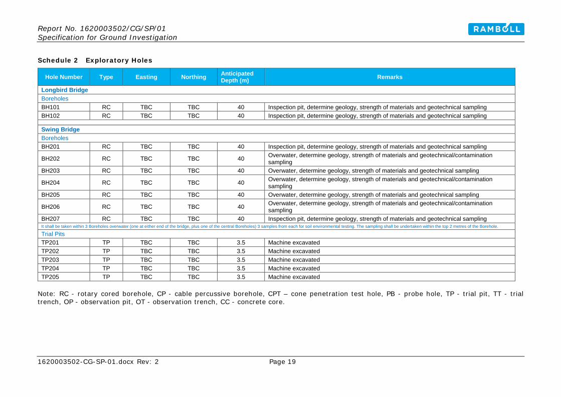
Schedule 2 Exploratory Holes
Hole Number Type Easting Northing Anticipated Depth (m) Remarks
Longbird Bridge Boreholes BH101 RC TBC TBC 40 Inspection pit, determine geology, strength of materials and geotechnical sampling BH102 RC TBC TBC 40 Inspection pit, determine geology, strength of materials and geotechnical sampling
Swing Bridge Boreholes BH201 RC TBC TBC 40 Inspection pit, determine geology, strength of materials and geotechnical sampling
BH202 RC TBC TBC 40 Overwater, determine geology, strength of materials and geotechnical/contamination sampling
BH203 RC TBC TBC 40 Overwater, determine geology, strength of materials and geotechnical sampling
BH204 RC TBC TBC 40 Overwater, determine geology, strength of materials and geotechnical/contamination sampling
BH205 RC TBC TBC 40 Overwater, determine geology, strength of materials and geotechnical sampling
BH206 RC TBC TBC 40 Overwater, determine geology, strength of materials and geotechnical/contamination sampling
BH207 RC TBC TBC 40 Inspection pit, determine geology, strength of materials and geotechnical sampling It shall be taken within 3 Boreholes overwater (one at either end of the bridge, plus one of the central Boreholes) 3 samples from each for soil environmental testing. The sampling shall be undertaken within the top 2 metres of the Borehole. Trial Pits TP201 TP TBC TBC 3.5 Machine excavated TP202 TP TBC TBC 3.5 Machine excavated TP203 TP TBC TBC 3.5 Machine excavated TP204 TP TBC TBC 3.5 Machine excavated TP205 TP TBC TBC 3.5 Machine excavated
Note: RC - rotary cored borehole, CP - cable percussive borehole, CPT – cone penetration test hole, PB - probe hole, TP - trial pit, TT - trial trench, OP - observation pit, OT - observation trench, CC - concrete core.
Report No. 1620003502/CG/SP/01 Specification for Ground Investigation
1620003502-CG-SP-01.docx Rev: 2 Page 20
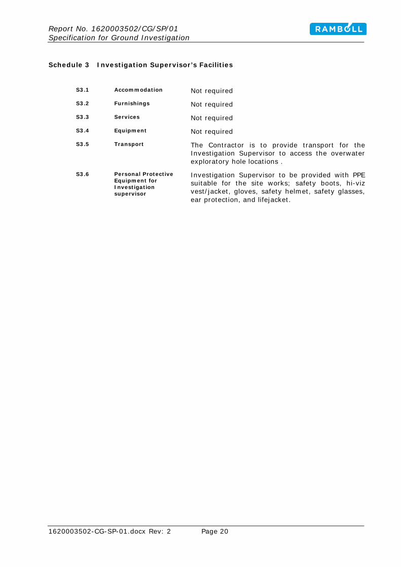
Schedule 3 Investigation Supervisor’s Facilities
S3.1 Accommodation Not required
S3.2 Furnishings Not required
S3.3 Services Not required
S3.4 Equipment Not required
S3.5 Transport The Contractor is to provide transport for the Investigation Supervisor to access the overwater exploratory hole locations .
S3.6 Personal Protective Equipment for Investigation supervisor
Investigation Supervisor to be provided with PPE suitable for the site works; safety boots, hi-viz vest/jacket, gloves, safety helmet, safety glasses, ear protection, and lifejacket.

Report No. 1620003502/CG/SP/01 Specification for Ground Investigation
1620003502-CG-SP-01.docx Rev: 2 Page 21
Schedule 4 Specification Amendments
None
Report No. 1620003502/CG/SP/01 Specification for Ground Investigation
1620003502-CG-SP-01.docx Rev: 2 Page 22
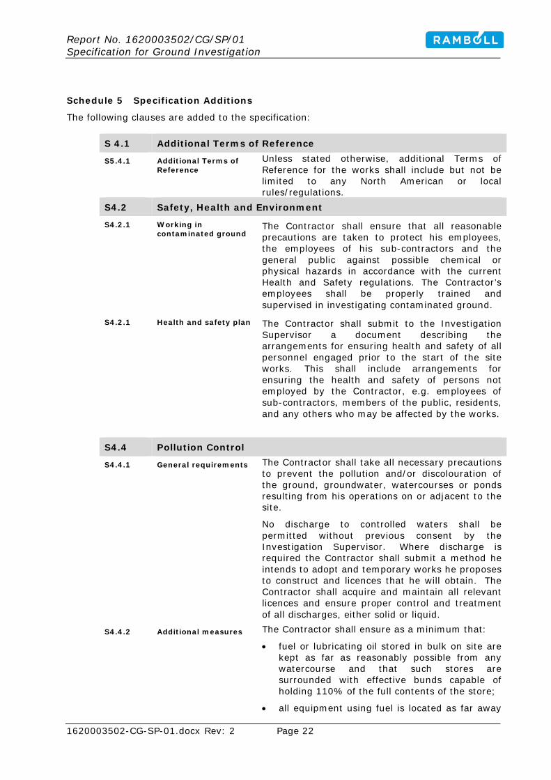
Schedule 5 Specification Additions
The following clauses are added to the specification:
S 4.1 Additional Terms of Reference
S5.4.1 Additional Terms of Reference
Unless stated otherwise, additional Terms of Reference for the works shall include but not be limited to any North American or local rules/regulations.
S4.2 Safety, Health and Environment
S4.2.1 Working in contaminated ground
The Contractor shall ensure that all reasonable precautions are taken to protect his employees, the employees of his sub-contractors and the general public against possible chemical or physical hazards in accordance with the current Health and Safety regulations. The Contractor’s employees shall be properly trained and supervised in investigating contaminated ground.
S4.2.1 Health and safety plan The Contractor shall submit to the Investigation Supervisor a document describing the arrangements for ensuring health and safety of all personnel engaged prior to the start of the site works. This shall include arrangements for ensuring the health and safety of persons not employed by the Contractor, e.g. employees of sub-contractors, members of the public, residents, and any others who may be affected by the works.
S4.4 Pollution Control
S4.4.1 General requirements The Contractor shall take all necessary precautions to prevent the pollution and/or discolouration of the ground, groundwater, watercourses or ponds resulting from his operations on or adjacent to the site.
No discharge to controlled waters shall be permitted without previous consent by the Investigation Supervisor. Where discharge is required the Contractor shall submit a method he intends to adopt and temporary works he proposes to construct and licences that he will obtain. The Contractor shall acquire and maintain all relevant licences and ensure proper control and treatment of all discharges, either solid or liquid.
S4.4.2 Additional measures The Contractor shall ensure as a minimum that:
• fuel or lubricating oil stored in bulk on site are kept as far as reasonably possible from any watercourse and that such stores are surrounded with effective bunds capable of holding 110% of the full contents of the store;
• all equipment using fuel is located as far away

Report No. 1620003502/CG/SP/01 Specification for Ground Investigation
1620003502-CG-SP-01.docx Rev: 2 Page 23
as possible from any watercourse. Any fuel transfer shall be via a fully closed system and spill kits shall be provided.
• no discharge or seepage of cement slurry, drilling fluids and cuttings to any controlled waters will occur.
In the event of a controlled water-body being polluted as a result of his works, the Contractor shall be responsible for taking immediate action to prevent the pollution spreading, and inform the Investigation Supervisor immediately.
S4.5 Waste Management
S4.5.1 General Waste Management requirements
The Contractor shall remove any surplus material after backfilling of the exploratory holes, and leave the site in a clean and tidy state to the satisfaction of the Investigation Supervisor. This shall include obtaining a skip for the storage of waste materials on site. The Contractor shall allow for the classification and disposal of any excess arisings from the Contractor's work to a suitably licensed disposal facility. All soil arisings shall be placed on plastic sheeting and not on Natural Ground, in order to prevent contamination of clean areas.
S4.5.2 Disposal of material off-site
Should any material be removed off-site the Contractor shall comply with all applicable Waste Management and Duty of Care regulations.

Report No. 1620003502/CG/SP/01 Specification for Ground Investigation
1620003502-CG-SP-01.docx Rev: 2 Page 24
ANNEX 1: BILL OF QUANTITIES FOR GROUND INVESTIGATION
Preamble
1. In this Bill of Quantities the sub-headings and item description identify the work covered by the respective items. The exact nature and extent of the work to be performed shall be ascertained by reference to the Conditions of Contract, the Specification and the Schedules and Appendices to the Specification as appropriate. The rates and prices entered in the Bill of Quantities shall be deemed to be the full inclusive value of then work covered by the several items, including the following unless stated otherwise:
a) Contract management and superintendence, labour and all costs in connection therewith;
b) the supply of materials, goods, storage, facilities and services, and all costs in connection therewith, including wastage and delivery to site;
c) plant and all costs in connection therewith; d) fixing, erecting and installing or placing of materials and goods in position; e) all temporary works; f) all general obligations, requirements, liabilities and risks involved in the
execution of the investigation as set forth or implied in the documents on which the tender is based;
g) establishment charges, overheads and profit; h) bringing plant and sampling and in-situ testing and monitoring equipment to
the site of each exploratory hole; erecting dismantling and removing on completion;
i) on completion, removal of all equipment and services from site and disposal of arisings.
2. Unless identified as Not Required, all items in Section A of the Bill of Quantities (general items, and provisional services and additional items), and all items in subsequent sections against which quantities are entered shall be priced.
3. If lump-sum items are not required by the Contractor, this shall be stated against the rate item in the Bill of Quantities and $0.00 entered in the amount. Where rates are not priced they shall have $0.00 placed against them and $0.00 entered in the amount.
4. When full or part-time professional attendance on site is required, this shall normally be paid for under Item A7 of the Bill of Quantities.
Unless otherwise detailed in Schedule S1.8.2, the on-site professional attendance services provided by the technical staff shall comprise the technical supervision of site activities, site liaison, logistics logging, in-situ testing and sampling, photography and the preparation of daily records and preliminary logs (except where any of the above activities are carried out by site operatives and boring/drilling operatives).
When individuals are not carrying out their specific duties are otherwise away from the site then daily rates will not apply and these costs will be deemed to be covered under general items.
5. The rate entered under Item A3 shall include for the provision of any additional PPE, ground surface protection measures, additional welfare and hygiene facilities and plant and equipment decontamination facilities required as a direct result of the contamination of hazard(s) detailed in Schedule S1.8.4 and/or S1.8.6.
6. The Item for photographs shall allow for the standing time of associated plant and supply of negatives, enprints and bound volume or electronic equivalents.
7. Rates for moving plant and equipment to the site of each exploratory hole shall

Report No. 1620003502/CG/SP/01 Specification for Ground Investigation
1620003502-CG-SP-01.docx Rev: 2 Page 25
allow for the formation of access routes, and making good avoidable damage to access routes and working areas on completion as required by the Contract.
8. The rates for moving rotary drilling plant to the site of each hole shall include for setting up over a previously formed borehole, including for any additional costs arising from pulling casings left in the ground or providing temporary casings
9. Payment for forming exploratory holes shall be based on:
a) full thickness of strata investigated and described in accordance with the Specification;
b) depths measured from ground level; c) depth measured from the original ground level where an inspection pit has
been excavated; d) that part of a drill hole below the bottom of a borehole where a drill hole has
been ordered to continue from the bottom of a borehole; e) core recovery of at least 90% in any core run, unless the Investigation
Supervisor is satisfied it cannot be achieved; f) volume calculated as measured length multiplied by measured depth
multiplied by specified width for trial and observation trenches.
10. Rates for forming exploratory holes shall allow for:
a) temporary casing installation, where necessary, and removal; b) dealing with surface water; c) backfilling with arisings; d) taking information and supply of daily record for the works carried out by
site operatives; e) additional site supervision of non-qualified operatives.
11. Rates for aquifer protection measures shall allow for the measures detailed in section S1.8.13.
12. Standing time shall be measured as the duration of time for which plant, equipment and personnel are standing on the instruction of the Investigation Supervisor or in accordance with the specification.
Standing time shall be paid for interruption of the formation of exploratory holes to record groundwater entry. The rates for standing time shall include for:
a) plant equipment and personnel; b) consequential costs; c) changes in the programme of working; d) recording information and preparing daily report.
13. The rates for daily provision of dynamic sampling and probing, hand augering and pitting and trenching crews and equipment at locations as directed by the Investigation Supervisor shall allow for compliance with the requirements of the Contract, including preparation of records (unless the Investigation Supervisor takes responsibility for the logging and preparation of records).
The rates for dynamic sampling Items B15 to B17 and B19 shall include for the provision of liners.
14. The rates for sampling shall allow for the standing time of associated plant. The rates for sampling shall also include for the costs of the sample containers and transport and storage of the samples up to the specified time limits.
The rate for taking U100 or UT100 sample does not include for recovery of a sample from the cutting shoe.
The rates for each of Items E14.1 to E15.3 shall include for all necessary containers and collected samples for an individual determination of the specified contamination or WAC suite.

Report No. 1620003502/CG/SP/01 Specification for Ground Investigation
1620003502-CG-SP-01.docx Rev: 2 Page 26
15. The rates for in-situ testing shall allow for the standing time of associated plant and for the interpretation and presentation of the results on preliminary logs/exploratory hole logs or on separate agreed report forms using the same dates of presentation as the exploratory hole to which they refer.
In the case of the self-boring pressuremeter, high pressure dilatometer or Menard pressuremeter, the rates shall also allow or the mutual standing of the respective boring/drilling plant and specialist testing equipment and crews during the combined process.
Where in-situ testing I paid for on an hourly basis, the time measured shall be the actual time taken to carry out the test in accordance with the Investigation Supervisor’s instruction and/or the Specification but excluding the time taken to erect and dismantle test equipment where this is itemised separately.
The rate for carrying out and SPT (whether using spit spoon or solid cone), does not include for the recovery of associated sample.
16. The rates for cone penetration test Items F15 and F21 shall allow for the provision of daily records and for the interpretation and presentation of the results on agreed report forms/exploratory hole logs in accordance with Schedules 1.13.3 or 1.13.4.
For the seismic cone, the recorded and presented data shall include the specified CPT data recorded between seismic test depths.
The rates for dynamic probing shall allow for undertaking and reporting torque measurements at the prescribed vertical intervals.
17. The rates for installation of instruments shall allow for:
a) clearing and keeping the hole free of unwanted materials; b) all costs associated with equipment, installation, specified seals, surround
and backfill materials excluding backfill below the instrument and surface terminal if appropriate;
c) Proving correct functioning; d) Delays due to installations including setting time for grout; e) Recording information and preparing daily record and additional reports.
18. The rates for monitoring and sampling of installations during the fieldwork period shall allow for:
a) Purging and dealing with disposal of recovered water b) All costs associated with consumables and provision of data recording
equipment to site c) Proving correct calibration and recalibration d) Recording information, preparing, updating and submitting additional reports
successively and at the completion of monitoring , including notification of any unexpected readings and/or variation in readings
e) Delays due to interruptions of other site activities.
The rates for recording of water level, ground gas or other monitoring measurement shall allow for notices of re-entry to the Investigation Supervisor, owners or occupiers affected by the location or access route.
19. The rates for laboratory testing shall include for:
a) The supply of a copy of the preliminary test results to the Investigation Supervisor
b) Notification of available test samples, failed tests and/or deviating samples (e.g. samples not correctly preserved)
c) The cost of determining a parameter (e.. moisture content or density), where that parameter forms part of the information to be reported for the specified test (e.g. undrained shear strength, consolidation test, or unconfined

Report No. 1620003502/CG/SP/01 Specification for Ground Investigation
1620003502-CG-SP-01.docx Rev: 2 Page 27
compressive strength) d) The disposal of samples in accordance with the relevant regulations.
20. The provisional sum, Item A6, for the off-site disposal of contaminated waste shall include for temporary storage and for organising the transport and disposal by a suitably licenced waste disposal contractor. Payment shall be made only against receipted invoices.
The costs of laboratory testing to determine the nature of the waste shall be covered by laboratory testing rates for tests actually completed and to an agreed schedule. Those sums shall be offset against the Provisional sum Item A6.
21. Appendix A to the Bill of Quantities (Rates for Ground Practitioners and other Personnel) shall be priced. The rates given will be used by the Investigation Supervisor to make an initial estimate of costs, where applicable, of employing the Contractor’s staff.
22. Items for the supply of the master and copies of the Desk Study Report, Ground Investigation Report and/or Geotechnical Design Report shall include for the printing and supply of the specified number of draft and final copies (Schedule S1.21.12). All other duties in compiling, preparing and checking the draft and final reports shall normally be paid for either under Item A7 of the Bill of Quantities or using the rates given under Appendix A.
23. Units of measurement: the following abbreviations shall be used for the units of measurements:
• Millimetres: mm • Metre: m • Kilometres: km • Square millimetres: mm² • Square metre: m² • Cubic metre: m3 • Square metre per day: m²/day • Linear meter: lin.m • Kilogramme: kg • Tonne: t • Sum: sum • Number: nr • Hour: h • Week: wk • Vehicle week: v.wk • Item: item • Day: day • Specimen day: sp.day • Person day: p.day
Preamble amendments and additions
24. The rates for performing laboratory tests of long duration shall include for all costs incurred whilst working outside normal hours.

Report No. 1620003502/CG/SP/01 Specification for Ground Investigation
1620003502-CG-SP-01.docx Rev: 2 Page 28
Bill of Quantities The following pages constitute the Bill of Quantities. There are 2 sets of Bill of Quantities included, one for the drilling contractor and a second for the Geotechnical Engineer for logging, sampling, laboratory testing, and reporting.
Report No. 1620003502/CG/SP/01 Specification for Ground Investigation
1620003502-CG-SP-01.docx Rev: 2 Page 29
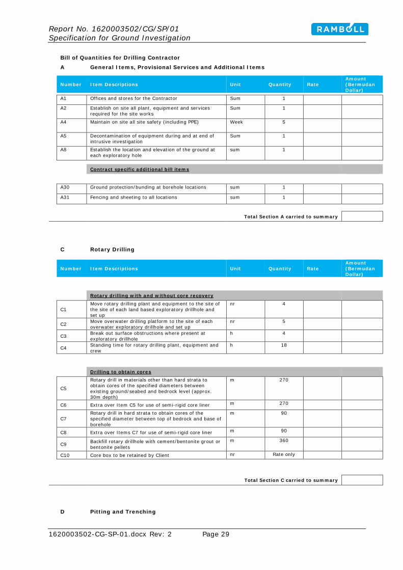
Bill of Quantities for Drilling Contractor
A General Items, Provisional Services and Additional Items
Number Item Descriptions Unit Quantity Rate Amount (Bermudan Dollar)
A1 Offices and stores for the Contractor Sum 1
A2 Establish on site all plant, equipment and services required for the site works
Sum 1
A4 Maintain on site all site safety (including PPE) Week 5
A5 Decontamination of equipment during and at end of intrusive investigation
Sum 1
A8 Establish the location and elevation of the ground at each exploratory hole
sum 1
Contract specific additional bill items
A30 Ground protection/bunding at borehole locations sum 1
A31 Fencing and sheeting to all locations sum 1
Total Section A carried to summary
C Rotary Drilling
Number Item Descriptions Unit Quantity Rate Amount (Bermudan Dollar)
Rotary drilling with and without core recovery
C1 Move rotary drilling plant and equipment to the site of the site of each land based exploratory drillhole and set up
nr 4
C2 Move overwater drilling platform to the site of each overwater exploratory drillhole and set up
nr 5
C3 Break out surface obstructions where present at
exploratory drillhole h 4
C4 Standing time for rotary drilling plant, equipment and
crew h 18
Drilling to obtain cores
C5
Rotary drill in materials other than hard strata to obtain cores of the specified diameters between existing ground/seabed and bedrock level (approx. 30m depth)
m 270
C6 Extra over Item C5 for use of semi-rigid core liner m 270
C7 Rotary drill in hard strata to obtain cores of the specified diameter between top of bedrock and base of borehole
m 90
C8 Extra over Items C7 for use of semi-rigid core liner m 90
C9 Backfill rotary drillhole with cement/bentonite grout or bentonite pellets
m 360
C10 Core box to be retained by Client nr Rate only
Total Section C carried to summary
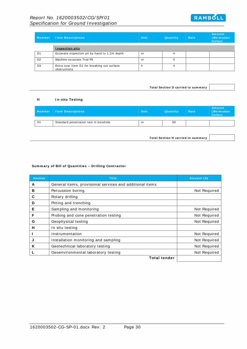
D Pitting and Trenching
Report No. 1620003502/CG/SP/01 Specification for Ground Investigation
1620003502-CG-SP-01.docx Rev: 2 Page 30
Number Item Descriptions Unit Quantity Rate Amount (Bermudan Dollar)
Inspection pits
D1 Excavate inspection pit by hand to 1.2m depth nr 4
D2 Machine excavate Trial Pit nr 5
D3 Extra over Item D1 for breaking out surface obstructions
h 4
Total Section D carried to summary
H In-situ Testing
Number Item Descriptions Unit Quantity Rate Amount (Bermudan Dollar)
H1 Standard penetration test in borehole nr 90
Total Section H carried to summary
Summary of Bill of Quantities – Drilling Contractor
Section Title Amount ($)
A General items, provisional services and additional items B Percussion boring Not Required C Rotary drilling D Pitting and trenching E Sampling and monitoring Not Required F Probing and cone penetration testing Not Required G Geophysical testing Not Required H In situ testing I Instrumentation Not Required J Installation monitoring and sampling Not Required K Geotechnical laboratory testing Not Required L Geoenvironmental laboratory testing Not Required
Total tender

Report No. 1620003502/CG/SP/01 Specification for Ground Investigation
1620003502-CG-SP-01.docx Rev: 2 Page 31
Bill of Quantities – Geotechnical Engineer for logging, sampling, testing, and reporting
A General Items, Provisional Services and Additional Items
Number Item Descriptions Unit Quantity Rate Amount (Bermudan Dollar)
A1 Offices and stores for the Engineer Sum 1
A2 Establish on site all plant, equipment and services required for the site works
Sum 1
A4 Provide and maintain site safety equipment (PPE) Week 5
A7 Provide professional attendance in accordance with Clause 3.5.2 for logging, sampling, testing, and reporting
Sum 1
A9 Preparation of Health and Safety documentation and Safety Risk Assessment
sum 1
A21 Preparation Electronic copy of Factual Investigation Report (or specified part thereof)
sum 1
A25 Digital data in AGS transfer format sum 1
A27 Photographic volume nr 1
A28 Long-term storage of geotechnical samples (Appendix B)
provisional sum
Total Section A carried to summary
E Sampling and Monitoring During Intrusive Investigation
Number Item Descriptions Unit Quantity Rate Amount (Bermudan Dollar)
Samples for geotechnical and contamination purposes
E1 Small disturbed sample nr 135
E2 Bulk disturbed sample nr 36
E8 Rotary core sub-sample (including cutting, preparation and protecting)
nr 27
E9 Contamination sample nr 15
E10 Surface water sample nr 4
Total Section E carried to summary
K Geotechnical Laboratory Testing
Number Item Descriptions Unit Quantity Rate Amount (Bermudan Dollar)
Provide current laboratory testing rates – provisional sum provided
12,500.00
Total Section K carried to summary
L Geo-environmental Laboratory Testing
Number Item Descriptions Unit Quantity Rate Amount (Bermuda Dollar)
Provide current laboratory testing rates – provisional sum provided 6,000.00
Total Section K carried to summary
Summary of Bill of Quantities

Report No. 1620003502/CG/SP/01 Specification for Ground Investigation
1620003502-CG-SP-01.docx Rev: 2 Page 32
Section Title Amount ($)
A General items, provisional services and additional items B Percussion boring Not Required C Rotary drilling Not Required D Pitting and trenching Not Required E Sampling and monitoring F Probing and cone penetration testing Not Required G Geophysical testing Not Required H In situ testing Not Required I Instrumentation Not Required J Installation monitoring and sampling Not required K Geotechnical laboratory testing 12,500.00 L Geoenvironmental laboratory testing 6,000.00
Total tender
Report No. 1620003502/CG/SP/01 Specification for Ground Investigation
1620003502-CG-SP-01.docx Rev: 2 Page 33
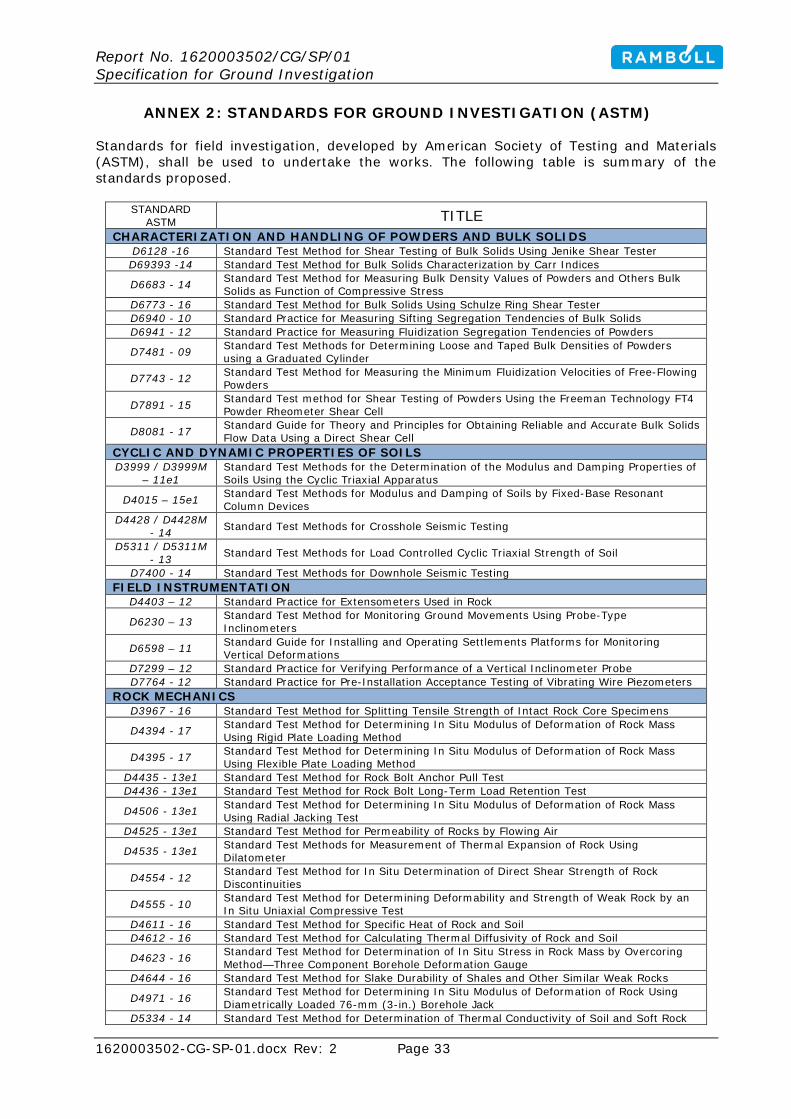
ANNEX 2: STANDARDS FOR GROUND INVESTIGATION (ASTM)
Standards for field investigation, developed by American Society of Testing and Materials (ASTM), shall be used to undertake the works. The following table is summary of the standards proposed.
STANDARD ASTM TITLE
CHARACTERIZATION AND HANDLING OF POWDERS AND BULK SOLIDS D6128 -16 Standard Test Method for Shear Testing of Bulk Solids Using Jenike Shear Tester D69393 -14 Standard Test Method for Bulk Solids Characterization by Carr Indices
D6683 - 14 Standard Test Method for Measuring Bulk Density Values of Powders and Others Bulk Solids as Function of Compressive Stress
D6773 - 16 Standard Test Method for Bulk Solids Using Schulze Ring Shear Tester D6940 - 10 Standard Practice for Measuring Sifting Segregation Tendencies of Bulk Solids D6941 - 12 Standard Practice for Measuring Fluidization Segregation Tendencies of Powders
D7481 - 09 Standard Test Methods for Determining Loose and Taped Bulk Densities of Powders using a Graduated Cylinder
D7743 - 12 Standard Test Method for Measuring the Minimum Fluidization Velocities of Free-Flowing Powders
D7891 - 15 Standard Test method for Shear Testing of Powders Using the Freeman Technology FT4 Powder Rheometer Shear Cell
D8081 - 17 Standard Guide for Theory and Principles for Obtaining Reliable and Accurate Bulk Solids Flow Data Using a Direct Shear Cell
CYCLIC AND DYNAMIC PROPERTIES OF SOILS D3999 / D3999M
– 11e1 Standard Test Methods for the Determination of the Modulus and Damping Properties of Soils Using the Cyclic Triaxial Apparatus
D4015 – 15e1 Standard Test Methods for Modulus and Damping of Soils by Fixed-Base Resonant Column Devices
D4428 / D4428M - 14 Standard Test Methods for Crosshole Seismic Testing
D5311 / D5311M - 13 Standard Test Methods for Load Controlled Cyclic Triaxial Strength of Soil
D7400 - 14 Standard Test Methods for Downhole Seismic Testing FIELD INSTRUMENTATION
D4403 – 12 Standard Practice for Extensometers Used in Rock
D6230 – 13 Standard Test Method for Monitoring Ground Movements Using Probe-Type Inclinometers
D6598 – 11 Standard Guide for Installing and Operating Settlements Platforms for Monitoring Vertical Deformations
D7299 – 12 Standard Practice for Verifying Performance of a Vertical Inclinometer Probe D7764 - 12 Standard Practice for Pre-Installation Acceptance Testing of Vibrating Wire Piezometers
ROCK MECHANICS D3967 - 16 Standard Test Method for Splitting Tensile Strength of Intact Rock Core Specimens
D4394 - 17 Standard Test Method for Determining In Situ Modulus of Deformation of Rock Mass Using Rigid Plate Loading Method
D4395 - 17 Standard Test Method for Determining In Situ Modulus of Deformation of Rock Mass Using Flexible Plate Loading Method
D4435 - 13e1 Standard Test Method for Rock Bolt Anchor Pull Test D4436 - 13e1 Standard Test Method for Rock Bolt Long-Term Load Retention Test
D4506 - 13e1 Standard Test Method for Determining In Situ Modulus of Deformation of Rock Mass Using Radial Jacking Test
D4525 - 13e1 Standard Test Method for Permeability of Rocks by Flowing Air
D4535 - 13e1 Standard Test Methods for Measurement of Thermal Expansion of Rock Using Dilatometer
D4554 - 12 Standard Test Method for In Situ Determination of Direct Shear Strength of Rock Discontinuities
D4555 - 10 Standard Test Method for Determining Deformability and Strength of Weak Rock by an In Situ Uniaxial Compressive Test
D4611 - 16 Standard Test Method for Specific Heat of Rock and Soil D4612 - 16 Standard Test Method for Calculating Thermal Diffusivity of Rock and Soil
D4623 - 16 Standard Test Method for Determination of In Situ Stress in Rock Mass by Overcoring Method—Three Component Borehole Deformation Gauge
D4644 - 16 Standard Test Method for Slake Durability of Shales and Other Similar Weak Rocks
D4971 - 16 Standard Test Method for Determining In Situ Modulus of Deformation of Rock Using Diametrically Loaded 76-mm (3-in.) Borehole Jack
D5334 - 14 Standard Test Method for Determination of Thermal Conductivity of Soil and Soft Rock
Report No. 1620003502/CG/SP/01 Specification for Ground Investigation
1620003502-CG-SP-01.docx Rev: 2 Page 34
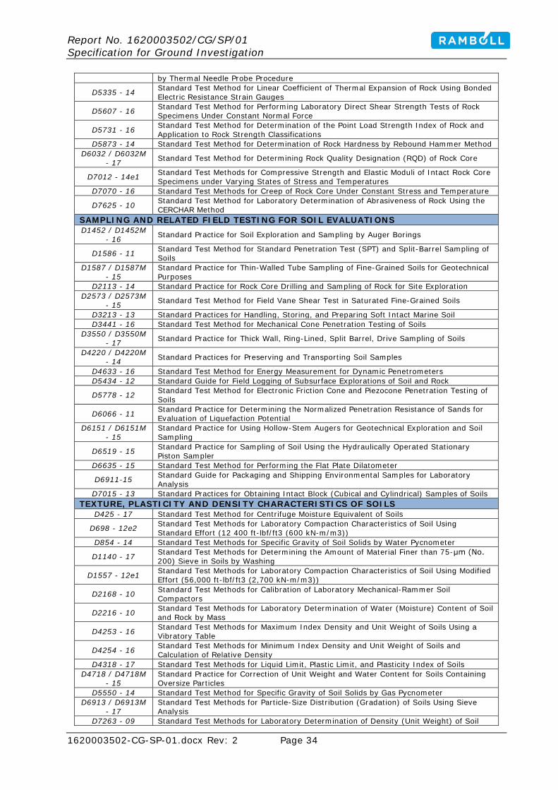
by Thermal Needle Probe Procedure
D5335 - 14 Standard Test Method for Linear Coefficient of Thermal Expansion of Rock Using Bonded Electric Resistance Strain Gauges
D5607 - 16 Standard Test Method for Performing Laboratory Direct Shear Strength Tests of Rock Specimens Under Constant Normal Force
D5731 - 16 Standard Test Method for Determination of the Point Load Strength Index of Rock and Application to Rock Strength Classifications
D5873 - 14 Standard Test Method for Determination of Rock Hardness by Rebound Hammer Method D6032 / D6032M
- 17 Standard Test Method for Determining Rock Quality Designation (RQD) of Rock Core
D7012 - 14e1 Standard Test Methods for Compressive Strength and Elastic Moduli of Intact Rock Core Specimens under Varying States of Stress and Temperatures
D7070 - 16 Standard Test Methods for Creep of Rock Core Under Constant Stress and Temperature
D7625 - 10 Standard Test Method for Laboratory Determination of Abrasiveness of Rock Using the CERCHAR Method
SAMPLING AND RELATED FIELD TESTING FOR SOIL EVALUATIONS D1452 / D1452M
- 16 Standard Practice for Soil Exploration and Sampling by Auger Borings
D1586 - 11 Standard Test Method for Standard Penetration Test (SPT) and Split-Barrel Sampling of Soils
D1587 / D1587M - 15
Standard Practice for Thin-Walled Tube Sampling of Fine-Grained Soils for Geotechnical Purposes
D2113 - 14 Standard Practice for Rock Core Drilling and Sampling of Rock for Site Exploration D2573 / D2573M
- 15 Standard Test Method for Field Vane Shear Test in Saturated Fine-Grained Soils
D3213 - 13 Standard Practices for Handling, Storing, and Preparing Soft Intact Marine Soil D3441 - 16 Standard Test Method for Mechanical Cone Penetration Testing of Soils
D3550 / D3550M - 17 Standard Practice for Thick Wall, Ring-Lined, Split Barrel, Drive Sampling of Soils
D4220 / D4220M - 14 Standard Practices for Preserving and Transporting Soil Samples
D4633 - 16 Standard Test Method for Energy Measurement for Dynamic Penetrometers D5434 - 12 Standard Guide for Field Logging of Subsurface Explorations of Soil and Rock
D5778 - 12 Standard Test Method for Electronic Friction Cone and Piezocone Penetration Testing of Soils
D6066 - 11 Standard Practice for Determining the Normalized Penetration Resistance of Sands for Evaluation of Liquefaction Potential
D6151 / D6151M - 15
Standard Practice for Using Hollow-Stem Augers for Geotechnical Exploration and Soil Sampling
D6519 - 15 Standard Practice for Sampling of Soil Using the Hydraulically Operated Stationary Piston Sampler
D6635 - 15 Standard Test Method for Performing the Flat Plate Dilatometer
D6911-15 Standard Guide for Packaging and Shipping Environmental Samples for Laboratory Analysis
D7015 - 13 Standard Practices for Obtaining Intact Block (Cubical and Cylindrical) Samples of Soils TEXTURE, PLASTICITY AND DENSITY CHARACTERISTICS OF SOILS
D425 - 17 Standard Test Method for Centrifuge Moisture Equivalent of Soils
D698 - 12e2 Standard Test Methods for Laboratory Compaction Characteristics of Soil Using Standard Effort (12 400 ft-lbf/ft3 (600 kN-m/m3))
D854 - 14 Standard Test Methods for Specific Gravity of Soil Solids by Water Pycnometer
D1140 - 17 Standard Test Methods for Determining the Amount of Material Finer than 75-μm (No. 200) Sieve in Soils by Washing
D1557 - 12e1 Standard Test Methods for Laboratory Compaction Characteristics of Soil Using Modified Effort (56,000 ft-lbf/ft3 (2,700 kN-m/m3))
D2168 - 10 Standard Test Methods for Calibration of Laboratory Mechanical-Rammer Soil Compactors
D2216 - 10 Standard Test Methods for Laboratory Determination of Water (Moisture) Content of Soil and Rock by Mass
D4253 - 16 Standard Test Methods for Maximum Index Density and Unit Weight of Soils Using a Vibratory Table
D4254 - 16 Standard Test Methods for Minimum Index Density and Unit Weight of Soils and Calculation of Relative Density
D4318 - 17 Standard Test Methods for Liquid Limit, Plastic Limit, and Plasticity Index of Soils D4718 / D4718M
- 15 Standard Practice for Correction of Unit Weight and Water Content for Soils Containing Oversize Particles
D5550 - 14 Standard Test Method for Specific Gravity of Soil Solids by Gas Pycnometer D6913 / D6913M
- 17 Standard Test Methods for Particle-Size Distribution (Gradation) of Soils Using Sieve Analysis
D7263 - 09 Standard Test Methods for Laboratory Determination of Density (Unit Weight) of Soil

Report No. 1620003502/CG/SP/01 Specification for Ground Investigation
1620003502-CG-SP-01.docx Rev: 2 Page 35
Specimens
D7928 - 17 Standard Test Method for Particle-Size Distribution (Gradation) of Fine-Grained Soils Using the Sedimentation (Hydrometer) Analysis
TEST METHODS C97 / C97M - 15 Standard Test Methods for Absorption and Bulk Specific Gravity of Dimension Stone C99 / C99M - 15 Standard Test Method for Modulus of Rupture of Dimension Stone C120 / C120M -
15a Standard Test Methods for Flexure Testing of Structural and Roofing Slate
C121 / C121M - 15 Standard Test Method for Water Absorption of Slate
C170 / C170M - 17 Standard Test Method for Compressive Strength of Dimension Stone
C217 / C217M - 15a Standard Test Method for Weather Resistance of Slate
C241 / C241M - 15e1 Standard Test Method for Abrasion Resistance of Stone Subjected to Foot Traffic
C880 / C880M - 15 Standard Test Method for Flexural Strength of Dimension Stone
C1201 / C1201M - 15
Standard Test Method for Structural Performance of Exterior Dimension Stone Cladding Systems by Uniform Static Air Pressure Difference
C1352 / C1352M - 15 Standard Test Method for Flexural Modulus of Elasticity of Dimension Stone
C1353 / C1353M - 15a
Standard Test Method for Abrasion Resistance of Dimension Stone Subjected to Foot Traffic Using a Rotary Platform Abraser
C1354 / C1354M - 15 Standard Test Method for Strength of Individual Stone Anchorages in Dimension Stone
C1721 - 15 Standard Guide for Petrographic Examination of Dimension Stone TERMINOLOGY FOR SOIL, ROCK AND CONTAINES FLUIDS
D653 - 14 Standard Terminology Relating to Soil, Rock, and Contained Fluids SURFACE AND SUBSURFACE CHARACTERIZATION
D5753 - 05(2010) Standard Guide for Planning and Conducting Borehole Geophysical Logging
D5777 - 00(2011)e1 Standard Guide for Using the Seismic Refraction Method for Subsurface Investigation
D5879 - 95(2010) Standard Practice for Surface Site Characterization for On-Site Septic Systems
D5921 - 96(2010)
Standard Practice for Subsurface Site Characterization of Test Pits for On-Site Septic Systems
D5922 - 96(2010) Standard Guide for Analysis of Spatial Variation in Geostatistical Site Investigations
D5923 - 96(2010) Standard Guide for Selection of Kriging Methods in Geostatistical Site Investigations
D5924 - 96(2010)
Standard Guide for Selection of Simulation Approaches in Geostatistical Site Investigations
D5995 - 98(2010) Standard Guide for Environmental Site Characterization in Cold Regions
D6167 - 11 Standard Guide for Conducting Borehole Geophysical Logging: Mechanical Caliper D6235 - 04(2010)
Standard Practice for Expedited Site Characterization of Vadose Zone and Groundwater Contamination at Hazardous Waste Contaminated Sites
D6274 - 10 Standard Guide for Conducting Borehole Geophysical Logging - Gamma D6429 -
99(2011)e1 Standard Guide for Selecting Surface Geophysical Methods
D6430 - 99(2010) Standard Guide for Using the Gravity Method for Subsurface Investigation
D6431 - 99(2010)
Standard Guide for Using the Direct Current Resistivity Method for Subsurface Investigation
D6432 - 11 Standard Guide for Using the Surface Ground Penetrating Radar Method for Subsurface Investigation
D6726 - 15 Standard Guide for Conducting Borehole Geophysical Logging—Electromagnetic Induction
D6727 / D6727M - 16 Standard Guide for Conducting Borehole Geophysical Logging—Neutron
D7046 - 11 Standard Guide for Use of the Metal Detection Method for Subsurface Exploration D7128 - 05(2010)
Standard Guide for Using the Seismic-Reflection Method for Shallow Subsurface Investigation
D7699 / D7699M - 11
Standard Practice for Minimum Geospatial Data for Abandoned Mine Land Problem Areas, Planning Units, Keyword Features, and Project Sites
D7780 - 12 Standard Practice for Geospatial Data for Representing Coal Mining Features STRENGTH AND COMPRESSIBILITY OF SOILS
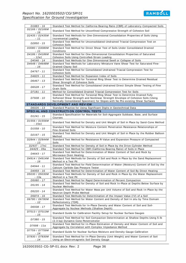
Report No. 1620003502/CG/SP/01 Specification for Ground Investigation
1620003502-CG-SP-01.docx Rev: 2 Page 36
D1883 - 16 Standard Test Method for California Bearing Ratio (CBR) of Laboratory-Compacted Soils D2166 / D2166M
- 16 Standard Test Method for Unconfined Compressive Strength of Cohesive Soil
D2435 / D2435M - 11
Standard Test Methods for One-Dimensional Consolidation Properties of Soils Using Incremental Loading
D2850 - 15 Standard Test Method for Unconsolidated-Undrained Triaxial Compression Test on Cohesive Soils
D3080 / D3080M - 11
Standard Test Method for Direct Shear Test of Soils Under Consolidated Drained Conditions
D4186 / D4186M - 12e1
Standard Test Method for One-Dimensional Consolidation Properties of Saturated Cohesive Soils Using Controlled-Strain Loading
D4546 - 14 Standard Test Methods for One-Dimensional Swell or Collapse of Soils D4648 / D4648M
- 16 Standard Test Methods for Laboratory Miniature Vane Shear Test for Saturated Fine-Grained Clayey Soil
D4767 - 11 Standard Test Method for Consolidated Undrained Triaxial Compression Test for Cohesive Soils
D4829 - 11 Standard Test Method for Expansion Index of Soils
D6467 - 13 Standard Test Method for Torsional Ring Shear Test to Determine Drained Residual Shear Strength of Cohesive Soils
D6528 - 17 Standard Test Method for Consolidated Undrained Direct Simple Shear Testing of Fine Grain Soils
D7181 - 11 Method for Consolidated Drained Triaxial Compression Test for Soils
D7608 - 10 Standard Test Method for Torsional Ring Shear Test to Determine Drained Fully Softened Shear Strength and Nonlinear Strength Envelope of Cohesive Soils (Using Normally Consolidated Specimen) for Slopes with No Pre-existing Shear Surfaces
STANDARDS DEVELOPMENT AND REVIEW D6026 - 13 Standard Practice for Using Significant Digits in Geotechnical Data
SPECIAL AND CONSTRUCTION CONTROL TESTS
D1241 - 15 Standard Specification for Materials for Soil-Aggregate Subbase, Base, and Surface Courses
D1556 / D1556M - 15e1 Standard Test Method for Density and Unit Weight of Soil in Place by Sand-Cone Method
D1558 - 10 Standard Test Method for Moisture Content Penetration Resistance Relationships of Fine-Grained Soils
D2167 - 15 Standard Test Method for Density and Unit Weight of Soil in Place by the Rubber Balloon Method
D2844 / D2844M - 13
Standard Test Method for Resistance R-Value and Expansion Pressure of Compacted Soils
D2937 - 17e1 Standard Test Method for Density of Soil in Place by the Drive-Cylinder Method D4429 - 09a Standard Test Method for CBR (California Bearing Ratio) of Soils in Place
D4643 - 17 Standard Test Method for Determination of Water Content of Soil and Rock by Microwave Oven Heating
D4914 / D4914M - 16
Standard Test Methods for Density of Soil and Rock in Place by the Sand Replacement Method in a Test Pit
D4944 - 11 Standard Test Method for Field Determination of Water (Moisture) Content of Soil by the Calcium Carbide Gas Pressure Tester
D4959 - 16 Standard Test Method for Determination of Water Content of Soil By Direct Heating D5030 / D5030M
- 13a Standard Test Methods for Density of Soil and Rock in Place by the Water Replacement Method in a Test Pit
D5080 - 17 Standard Test Method for Rapid Determination of Percent Compaction
D5195 - 14 Standard Test Method for Density of Soil and Rock In-Place at Depths Below Surface by Nuclear Methods
D5220 - 14 Standard Test Method for Water Mass per Unit Volume of Soil and Rock In-Place by the Neutron Depth Probe Method
D5874 - 16 Standard Test Methods for Determination of the Impact Value (IV) of a Soil D6780 / D6780M
- 12 Standard Test Method for Water Content and Density of Soil In situ by Time Domain Reflectometry (TDR)
D6938 - 17 Standard Test Methods for In-Place Density and Water Content of Soil and Soil-Aggregate by Nuclear Methods (Shallow Depth)
D7013 / D7013M - 15 Standard Guide for Calibration Facility Setup for Nuclear Surface Gauges
D7380 - 15 Standard Test Method for Soil Compaction Determination at Shallow Depths Using 5-lb (2.3 kg) Dynamic Cone Penetrometer
D7698 - 11a Standard Test Method for In-Place Estimation of Density and Water Content of Soil and Aggregate by Correlation with Complex Impedance Method
D7759 / D7759M - 14 Standard Guide for Nuclear Surface Moisture and Density Gauge Calibration
D7830 / D7830M - 14
Standard Test Method for In-Place Density (Unit Weight) and Water Content of Soil Using an Electromagnetic Soil Density Gauge
Report No. 1620003502/CG/SP/01 Specification for Ground Investigation
1620003502-CG-SP-01.docx Rev: 2 Page 37
ROCK FOR EROSION CONTROL D4992 - 14e1 Standard Practice for Evaluation of Rock to be Used for Erosion Control D5121 - 15 Standard Practice for Preparation of Rock Slabs for Durability Testing
D5240 / D5240M - 12(2013)
Standard Test Method for Evaluation of Durability of Rock for Erosion Control Using Sodium Sulfate or Magnesium Sulfate
D5312 / D5312M - 12(2013)
Standard Test Method for Evaluation of Durability of Rock for Erosion Control Under Freezing and Thawing Conditions
D5313 / D5313M - 12(2013)
Standard Test Method for Evaluation of Durability of Rock for Erosion Control Under Wetting and Drying Conditions
D5519 - 15 Standard Test Methods for Particle Size Analysis of Natural and Man-Made Riprap Materials
D5779 / D5779M - 14
Standard Test Method for Field Determination of Apparent Specific Gravity of Rock and Manmade Materials for Erosion Control
D6092 - 14 Standard Practice for Specifying Standard Sizes of Stone for Erosion Control D6473 - 15 Standard Test Method For Specific Gravity And Absorption of Rock For Erosion Control D6825 - 14 Standard Guide for Placement of Riprap Revetments
QUALITY CONTROL
D3740 - 12a Standard Practice for Minimum Requirements for Agencies Engaged in Testing and/or Inspection of Soil and Rock as Used in Engineering Design and Construction
D5255 - 15 Standard Practice for Certification of Personnel Engaged in the Testing of Soil and Rock PHYSICAL-CHEMICAL INTERACTIONS OF SOIL AND ROCK
D4221 - 17 Standard Test Method for Dispersive Characteristics of Clay Soil by Double Hydrometer D4373 - 14 Standard Test Method for Rapid Determination of Carbonate Content of Soils
D4404 - 10 Standard Test Method for Determination of Pore Volume and Pore Volume Distribution of Soil and Rock by Mercury Intrusion Porosimetry
D4542 - 15 Standard Test Methods for Pore Water Extraction and Determination of the Soluble Salt Content of Soils by Refractometer
D4647 / D4647M - 13
Standard Test Methods for Identification and Classification of Dispersive Clay Soils by the Pinhole Test
D5143 - 06(2015)e1
Standard Test Method for Analysis of Nitroaromatic and Nitramine Explosive in Soil by High Performance Liquid Chromatography
D6572 - 13e2 Standard Test Methods for Determining Dispersive Characteristics of Clayey Soils by the Crumb Test
D7458 - 14 Standard Test Method for Determination of Beryllium in Soil, Rock, Sediment, and Fly Ash Using Ammonium Bifluoride Extraction and Fluorescence Detection
PERMEABILITY AND FILTRATION D4491 / D4491M
- 17 Standard Test Methods for Water Permeability of Geotextiles by Permittivity
D4716 / D4716M - 14
Standard Test Method for Determining the (In-plane) Flow Rate per Unit Width and Hydraulic Transmissivity of a Geosynthetic Using a Constant Head
D4751 - 16 Standard Test Methods for Determining Apparent Opening Size of a Geotextile D5101 - 12(2017)
Standard Test Method for Measuring the Filtration Compatibility of Soil-Geotextile Systems
D5141 - 11 Standard Test Method for Determining Filtering Efficiency and Flow Rate of the Filtration Component of a Sediment Retention Device
D5199 - 12 Standard Test Method for Measuring the Nominal Thickness of Geosynthetics D5493 - 06(2016) Standard Test Method for Permittivity of Geotextiles Under Load
D5567 - 94(2011)
Standard Test Method for Hydraulic Conductivity Ratio (HCR) Testing of Soil/Geotextile Systems
D6088 - 06(2016) Standard Practice for Installation of Geocomposite Pavement Drains
D6140 - 00(2014)
Standard Test Method to Determine Asphalt Retention of Paving Fabrics Used in Asphalt Paving for Full-Width Applications
D6523 - 00(2014)e1
Standard Guide for Evaluation and Selection of Alternative Daily Covers (ADCs) for Sanitary Landfills
D6574 / D6574M - 13e1
Standard Test Method for Determining the (In-Plane) Hydraulic Transmissivity of a Geosynthetic by Radial Flow
D6767 - 16 Standard Test Method for Pore Size Characteristics of Geotextiles by Capillary Flow Test D6917 - 16 Standard Guide for Selection of Test Methods for Prefabricated Vertical Drains (PVD)
D6918 - 09(2014)e1 Standard Test Method for Testing Vertical Strip Drains in the Crimped Condition
D7178 - 16e1 Standard Practice for Determining the Number of Constrictions “m” of Non-Woven Geotextiles as a Complementary Filtration Property
D7180 / D7180M - 05(2013)e1
Standard Guide for Use of Expanded Polystyrene (EPS) Geofoam in Geotechnical Projects
D7498 / D7498M - 09(2014)e1 Standard Test Method for Vertical Strip Drains Using a Large Scale Consolidation Test
D7557 / D7557M Standard Practice for Sampling of Expanded Polystyrene Geofoam Specimens
Report No. 1620003502/CG/SP/01 Specification for Ground Investigation
1620003502-CG-SP-01.docx Rev: 2 Page 38
- 09(2013)e1
D7701 - 11 Standard Test Method for Determining the Flow Rate of Water and Suspended Solids from a Geotextile Bag
D7880 / D7880M - 13
Standard Test Method for Determining Flow Rate of Water and Suspended Solids Retention from a Closed Geosynthetic Bag
D7931 - 17 Standard Guide for Specifying Drainage Geocomposites D8057 - 17 Standard Specification for Inlet Filters with a Rigid Frame
NOMENCLATURE AND DEFINITIONS C119 - 16 Standard Terminology Relating to Dimension Stone
INFORMATION RETRIEVAL AND DATA AUTOMATION D4753 - 15
Standard Guide for Evaluating, Selecting, and Specifying Balances and Standard Masses for Use in Soil, Rock, and Construction Materials Testing
D5720 - 95(2009)
Standard Practice for Static Calibration of Electronic Transducer-Based Pressure Measurement Systems for Geotechnical Purposes
D6027 / D6027M - 15
Standard Practice for Calibrating Linear Displacement Transducers for Geotechnical Purposes
IDENTIFICATION AND CLASSIFICATION OF SOILS
D2487 - 11
Standard Practice for Classification of Soils for Engineering Purposes (Unified Soil Classification System)
D2488 - 17 Standard Practice for Description and Identification of Soils (Visual-Manual Procedures)
D3282 - 15
Standard Practice for Classification of Soils and Soil-Aggregate Mixtures for Highway Construction Purposes
D4427 - 13(2017)
Standard Classification of Peat Samples by Laboratory Testing
D4452 - 14 Standard Practice for X-Ray Radiography of Soil Samples
HYDROLOGIC PROPERTIES AND HYDRAULIC BARRIERS
D3385 - 09
Standard Test Method for Infiltration Rate of Soils in Field Using Double-Ring Infiltrometer
D4511 - 11 Standard Test Method for Hydraulic Conductivity of Essentially Saturated Peat
D5084 - 16a
Standard Test Methods for Measurement of Hydraulic Conductivity of Saturated Porous Materials Using a Flexible Wall Permeameter
D5093 - 15
Standard Test Method for Field Measurement of Infiltration Rate Using Double-Ring Infiltrometer with Sealed-Inner Ring
D5298 - 16 Standard Test Method for Measurement of Soil Potential (Suction) Using Filter Paper
D5856 - 15
Standard Test Method for Measurement of Hydraulic Conductivity of Porous Material Using a Rigid-Wall, Compaction-Mold Permeameter
D6391 - 11
Standard Test Method for Field Measurement of Hydraulic Conductivity Using Borehole Infiltration
D6539 - 13
Standard Test Method for Measurement of the Permeability of Unsaturated Porous Materials by Flowing Air
D6836 - 16
Standard Test Methods for Determination of the Soil Water Characteristic Curve for Desorption Using Hanging Column, Pressure Extractor, Chilled Mirror Hygrometer, or Centrifuge
D7100 - 11
Standard Test Method for Hydraulic Conductivity Compatibility Testing of Soils with Aqueous Solutions
D7243 - 11
Standard Guide for Measuring the Saturated Hydraulic Conductivity of Paper Industry Sludges
D7503 - 10
Standard Test Method for Measuring the Exchange Complex and Cation Exchange Capacity of Inorganic Fine-Grained Soils
D7664 - 10 Standard Test Methods for Measurement of Hydraulic Conductivity of Unsaturated Soils
HYDRAULIC FRACTURING
D8006 - 16
Standard Guide for Sampling and Analysis of Residential and Commercial Water Supply Wells in Areas of Exploration and Production (E&P) Operations
GROUNDWATER AND VADOSE ZONE INVESTIGATIONS D3404 - 15 Standard Guide for Measuring Matric Potential in Vadose Zone Using Tensiometers
D4043 - 17
Standard Guide for Selection of Aquifer Test Method in Determining Hydraulic Properties by Well Techniques
D4044 / D4044M - 15
Standard Test Method for (Field Procedure) for Instantaneous Change in Head (Slug) Tests for Determining Hydraulic Properties of Aquifers
D4050 - 14
Standard Test Method for (Field Procedure) for Withdrawal and Injection Well Testing for Determining Hydraulic Properties of Aquifer Systems
D4104 - 96(2010)e1
Standard Test Method (Analytical Procedure) for Determining Transmissivity of Nonleaky Confined Aquifers by Overdamped Well Response to Instantaneous Change in Head (Slug Tests)
D4700 - 15 Standard Guide for Soil Sampling from the Vadose Zone
D5088 - 15a Standard Practice for Decontamination of Field Equipment Used at Waste Sites
D5092 / D5092M - 16
Standard Practice for Design and Installation of Groundwater Monitoring Wells
D5126 - 16e1 Standard Guide for Comparison of Field Methods for Determining Hydraulic Conductivity

Report No. 1620003502/CG/SP/01 Specification for Ground Investigation
1620003502-CG-SP-01.docx Rev: 2 Page 39
in Vadose Zone
D5254 / D5254M - 92(2010)e1
Standard Practice for Minimum Set of Data Elements to Identify a Groundwater Site
D5269 - 15
Standard Test Method for Determining Transmissivity of Nonleaky Confined Aquifers by the Theis Recovery Method
D5270 - 96(2014)
Standard Test Method for Determining Transmissivity and Storage Coefficient of Bounded, Nonleaky, Confined Aquifers
D5299 - 99(2012)e1
Standard Guide for Decommissioning of Groundwater Wells, Vadose Zone Monitoring Devices, Boreholes, and Other Devices for Environmental Activities
D5408 - 93(2010)e1
Standard Guide for Set of Data Elements to Describe a Groundwater Site; Part One - Additional Identification Descriptors
D5409 / D5409M - 93(2010)e1
Standard Guide for Set of Data Elements to Describe a Groundwater Site; Part Two - Physical Descriptors
D5447 - 04(2010)
Standard Guide for Application of a Groundwater Flow Model to a Site-Specific Problem
D5472 / D5472M - 14
Standard Test Method for Determining Specific Capacity and Estimating Transmissivity at the Control Well
D5474 - 93(2012)
Standard Guide for Selection of Data Elements for Groundwater Investigations
D5490 - 93(2014)e1
Standard Guide for Comparing Groundwater Flow Model Simulations to Site-Specific Information
D5521 / D5521M - 13
Standard Guide for Development of Groundwater Monitoring Wells in Granular Aquifers
D5608 - 16
Standard Practices for Decontamination of Sampling and Non Sample Contacting Equipment Used at Low Level Radioactive Waste Sites
D5609 - 16 Standard Guide for Defining Boundary Conditions in Groundwater Flow Modelling
D5610 - 94(2014)
Standard Guide for Defining Initial Conditions in Groundwater Flow Modelling
D5611 - 94(2016)
Standard Guide for Conducting a Sensitivity Analysis for a Groundwater Flow Model Application
D5716 / D5716M - 15
Standard Test Method for Measuring the Rate of Well Discharge by Circular Orifice Weir
D5718 - 13 Standard Guide for Documenting a Groundwater Flow Model Application
D5719 - 13
Standard Guide for Simulation of Subsurface Airflow Using Groundwater Flow Modelling Codes
D5737 / D5737M - 14
Standard Guide for Methods for Measuring Well Discharge
D5781 / D5781M - 13
Standard Guide for Use of Dual-Wall Reverse-Circulation Drilling for Geoenvironmental Exploration and the Installation of Subsurface Water-Quality Monitoring Devices
D5782 - 95(2012)
Standard Guide for Use of Direct Air-Rotary Drilling for Geoenvironmental Exploration and the Installation of Subsurface Water-Quality Monitoring Devices
D5783 - 95(2012)
Standard Guide for Use of Direct Rotary Drilling with Water-Based Drilling Fluid for Geoenvironmental Exploration and the Installation of Subsurface Water-Quality Monitoring Devices
D5784 / D5784M - 13
Standard Guide for Use of Hollow-Stem Augers for Geoenvironmental Exploration and the Installation of Subsurface Water-Quality Monitoring Devices
D5785 / D5785M - 15
Standard Test Method for (Analytical Procedure) for Determining Transmissivity of Confined Nonleaky Aquifers by Underdamped Well Response to Instantaneous Change in Head (Slug Test)
D5786 - 17
Standard Practice for (Field Procedure) for Constant Drawdown Tests in Flowing Wells for Determining Hydraulic Properties of Aquifer Systems
D5787 - 14 Standard Practice for Monitoring Well Protection
D5850 - 95(2012)
Standard Test Method for (Analytical Procedure) Determining Transmissivity, Storage Coefficient, and Anisotropy Ratio from a Network of Partially Penetrating Wells
D5855 / D5855M - 15
Standard Test Method for (Analytical Procedure) for Determining Transmissivity and Storage Coefficient of Confined Nonleaky or Leaky Aquifer by Constant Drawdown Method in Flowing Well
D5872 / D5872M - 13
Standard Guide for Use of Casing Advancement Drilling Methods for Geoenvironmental Exploration and Installation of Subsurface Water-Quality Monitoring Devices
D5875 / D5875M - 13
Standard Guide for Use of Cable-Tool Drilling and Sampling Methods for Geoenvironmental Exploration and Installation of Subsurface Water-Quality Monitoring Devices
D5876 - 95(2012)e1
Standard Guide for Use of Direct Rotary Wireline Casing Advancement Drilling Methods for Geoenvironmental Exploration and Installation of Subsurface Water-Quality Monitoring Devices
D5881 - 13
Standard Test Method for (Analytical Procedure) Determining Transmissivity of Confined Nonleaky Aquifers by Critically Damped Well Response to Instantaneous Change in Head (Slug)
D5903 - 96(2017)e1
Standard Guide for Planning and Preparing for a Groundwater Sampling Event
Report No. 1620003502/CG/SP/01 Specification for Ground Investigation
1620003502-CG-SP-01.docx Rev: 2 Page 40
D5911 / D5911M - 96(2010)e1
Standard Practice for Minimum Set of Data Elements to Identify a Soil Sampling Site
D5920 - 14
Standard Test Method [Analytical Procedure] for Tests of Anisotropic Unconfined Aquifers by Neuman Method
D5978 / D5978M - 16
Standard Guide for Maintenance and Rehabilitation of Groundwater Monitoring Wells
D5979 - 96(2014)
Standard Guide for Conceptualization and Characterization of Groundwater Systems
D5980 - 16
Standard Guide for Selection and Documentation of Existing Wells for Use in Environmental Site Characterization and Monitoring
D6000 / D6000M - 15e1
Standard Guide for Presentation of Water-Level Information from Groundwater Sites
D6001 - 05(2012)
Standard Guide for Direct-Push Groundwater Sampling for Environmental Site Characterization
D6028 - 17
Standard Test Method (Analytical Procedure) for Determining Hydraulic Properties of a Confined Aquifer Taking into Consideration Storage of Water in Leaky Confining Beds by Modified Hantush Method
D6029 - 17
Standard Test Method (Analytical Procedure) for Determining Hydraulic Properties of a Confined Aquifer and a Leaky Confining Bed with Negligible Storage by the Hantush-Jacob Method
D6030 - 15
Standard Guide for Selection of Methods for Assessing Groundwater or Aquifer Sensitivity and Vulnerability
D6031 / D6031M - 96(2015)
Standard Test Method for Logging In Situ Moisture Content and Density of Soil and Rock by the Nuclear Method in Horizontal, Slanted, and Vertical Access Tubes
D6033 - 16 Standard Guide for Describing the Functionality of a Groundwater Modelling Code
D6034 - 17
Standard Test Method (Analytical Procedure) for Determining the Efficiency of a Production Well in a Confined Aquifer from a Constant Rate Pumping Test
D6036 - 96(2014)
Standard Guide for Displaying the Results of Chemical Analyses of Groundwater for Major Ions and Trace Elements—Use of Maps
D6067 - 10
Standard Practice for Using the Electronic Piezocone Penetrometer Tests for Environmental Site Characterization
D6089 - 15 Standard Guide for Documenting a Groundwater Sampling Event
D6106 - 97(2010)
Standard Guide for Establishing Nomenclature of Groundwater Aquifers
D6168 - 97(2010)
Standard Guide for Selection of Minimum Set of Data Elements Required to Identify Locations Chosen for Field Collection of Information to Describe Soil, Rock, and Their Contained Fluids
D6169 / D6169M - 13
Standard Guide for Selection of Soil and Rock Sampling Devices Used With Drill Rigs for Environmental Investigations
D6170 - 17 Standard Guide for Selecting a Groundwater Modelling Code
D6171 - 97(2010)
Standard Guide for Documenting a Groundwater Modelling Code
D6187 - 97(2010)
Standard Practice for Cone Penetrometer Technology Characterization of Petroleum Contaminated Sites with Nitrogen Laser-Induced Fluorescence
D6282 / D6282M - 14
Standard Guide for Direct Push Soil Sampling for Environmental Site Characterizations
D6285 - 99(2016)
Standard Guide for Locating Abandoned Wells
D6286 - 12 Standard Guide for Selection of Drilling Methods for Environmental Site Characterization
D6312 - 17
Standard Guide for Developing Appropriate Statistical Approaches for Groundwater Detection Monitoring Programs at Waste Disposal Facilities
D6452 - 99(2012)e1
Standard Guide for Purging Methods for Wells Used for Groundwater Quality Investigations
D6517 - 00(2012)e1
Standard Guide for Field Preservation of Groundwater Samples
D6564 - 00(2012)e1
Standard Guide for Field Filtration of Groundwater Samples
D6634 / D6634M - 14
Standard Guide for the Selection of Purging and Sampling Devices for Groundwater Monitoring Wells
D6724 / D6724M - 16
Standard Guide for Installation of Direct Push Groundwater Monitoring Wells
D6725 / D6725M - 16
Standard Practice for Direct Push Installation of Prepacked Screen Monitoring Wells in Unconsolidated Aquifers
D6911 - 15
Standard Guide for Packaging and Shipping Environmental Samples for Laboratory Analysis
D6914 / D6914M - 16
Standard Practice for Sonic Drilling for Site Characterization and the Installation of Subsurface Monitoring Devices
D7045 - 17
Standard Guide for Optimization of Groundwater Monitoring Constituents for Detection Monitoring Programs for Waste Disposal Facilities
D7048 - 16 Standard Guide for Applying Statistical Methods for Assessment and Corrective Action

Report No. 1620003502/CG/SP/01 Specification for Ground Investigation
1620003502-CG-SP-01.docx Rev: 2 Page 41
Environmental Monitoring Programs
D7069 - 04(2015)
Standard Guide for Field Quality Assurance in a Groundwater Sampling Event
D7242 / D7242M - 06(2013)e1
Standard Practice for Field Pneumatic Slug (Instantaneous Change in Head) Tests to Determine Hydraulic Properties of Aquifers with Direct Push Groundwater Samplers
D7262 - 10(2016)e1
Standard Test Method for Estimating the Permanganate Natural Oxidant Demand of Soil and Aquifer Solids
D7352 - 07(2012)
Standard Practice for Direct Push Technology for Volatile Contaminant Logging with the Membrane Interface Probe (MIP)
D7626 - 10 Standard Test Methods for Determining the Organic Treat Loading of Organophilic Clay
D7648 - 12
Standard Practice for Active Soil Gas Sampling for Direct Push or Manual-Driven Hand-Sampling Equipment
D7663 - 12
Standard Practice for Active Soil Gas Sampling in the Vadose Zone for Vapor Intrusion Evaluations
D7758 - 17
Standard Practice for Passive Soil Gas Sampling in the Vadose Zone for Source Identification, Spatial Variability Assessment, Monitoring, and Vapor Intrusion Evaluations
D7929 - 14
Standard Guide for Selection of Passive Techniques for Sampling Groundwater Monitoring Wells
D8037 / D8037M - 16
Standard Practice for Direct Push Hydraulic Logging for Profiling Variations of Permeability in Soils
D8106 - 17 Standard Test Methods for Determining the Oil Sorption Capacity of Organophilic Clay
D8038 - 16 Standard Practice for Reclamation of Recycled Aggregate Base (RAB) Material
EROSION AND SEDIMENT CONTROL TECHNOLOGY D6449 - 99(2015)
Standard Test Method for Flow of Fine Aggregate Concrete for Fabric Formed Concrete (Flow Cone Method)
D6459 - 15
Standard Test Method for Determination of Rolled Erosion Control Product (RECP) Performance in Protecting Hillslopes from Rainfall-Induced Erosion
D6460 - 12
Standard Test Method for Determination of Rolled Erosion Control Product (RECP) Performance in Protecting Earthen Channels from Stormwater-Induced Erosion
D6461 / D6461M - 16a
Standard Specifications for Silt Fence Materials
D6475 - 17 Standard Test Method for Measuring Mass per Unit Area of Erosion Control Blankets
D6599 - 00(2014)e1
Standard Practice for Construction of Live Fascines on Slopes
D6629 - 01(2012)e1
Standard Guide for Selection of Methods for Estimating Soil Loss by Erosion
D6684 - 04(2010)
Standard Specification for Materials and Manufacture of Articulating Concrete Block (ACB) Revetment Systems
D6685 - 01(2015)
Standard Guide for the Selection of Test Methods for Fabrics Used for Fabric Formed Concrete (FFC)
D6711 - 15
Standard Practice for Specifying Rock to Fill Gabions, Revet Mattresses, and Gabion Mattresses
D6765 - 13 Standard Practice for Live Staking
D6884 - 03(2015)e1
Standard Practice for Installation of Articulating Concrete Block (ACB) Revetment Systems
D7014 - 10
Standard Practice for Assembly and Placement of Double-Twisted Wire Mesh Gabions and Revet Mattresses
D7047 - 15e1 Standard Test Method for Swell Volume of Plantago Insularis (Ovata, Psyllium)
D7101 - 13
Standard Index Test Method for Determination of Unvegetated Rolled Erosion Control Product (RECP) Ability to Protect Soil from Rain Splash and Associated Runoff Under Bench-Scale Conditions
D7208 - 14
Standard Test Method for Determination of Temporary Ditch Check Performance in Protecting Earthen Channels from Stormwater-Induced Erosion
D7276 - 16
Standard Guide for Analysis and Interpretation of Test Data for Articulating Concrete Block (ACB) Revetment Systems in Open Channel Flow
D7277 - 16
Standard Test Method for Performance Testing of Articulating Concrete Block (ACB) Revetment Systems for Hydraulic Stability in Open Channel Flow
D7322 / D7322M - 17
Standard Test Method for Determination of Erosion Control Product (ECP) Ability to Encourage Seed Germination and Plant Growth Under Bench-Scale Conditions
D7351 - 13
Standard Test Method for Determination of Sediment Retention Device Effectiveness in Sheet Flow Applications
D7560 - 16
Standard Test Method for Determination of Fiber Length Percentages in Hydraulic Erosion Control Products (HECPs)
D7986 - 17a
Standard Practice for Preparing Specimens of Hydraulic Erosion Control Products for Index Property Testing
D8107 - 17 Standard Practice for Determining Sediment Pond Skimmer Flow Rate

Report No. 1620003502/CG/SP/01 Specification for Ground Investigation
1620003502-CG-SP-01.docx Rev: 2 Page 42
ANNEX 3: INFORMATION FOR DAILY RECORDS
Req. – Means information required (Req.) – Means information required if applicable. Percussion
boring (including dynamic sampling)
Rotary drilling (including augering and sonic drilling)
Pitting and trenching
Continuous and semi continuous sampling
Dynamic probing and static cone testing
Measurements, observations and test results (where separate from other exploratory holes)
1. Contract tittle and site name Req. Req. Req. Req. Req. Req. 2. Contractor’s and crew names Req. Req. Req. Req. Req. Req. 3. CSCS, BDA Audit or similar registration number Req. Req. Req. Req. Req. 4. Exploratory hole or location number Req. Req. Req. Req. Req. Req. 5. Day and Date Req. Req. Req. Req. Req. Req. 6. CAT scan details and type and depth of any services or drains encountered Req. Req. Req. Req. Req. (Req.) 7. Equipment and technique in use Req. Req. Req. Req. Req. Req. 8. Diameter and depth of holes and casing Req. Req. Req. (Req.) (Req.) 9. The depths at which any water was added and the volume of water used Req. 10. Depth of each change of stratum Req. Req. Req. Req. (Req.) (Req.) 11. Description of each stratum including visual and olfactory (where safe to do so) observations and any evidence of sidewall/basal instability.
Req. Req. Req. Req. (Req.)
12. The types of samples, the depths from/over which they were taken and length of undisturbed or core sub-samples recovered, the method used and the number of blows required to drive open-tube samples.
Req. (Req.) Req. (Req.) (Req.) (Req.)
13. The depths and details of all in situ tests. Req. Req. Req. (Req.) (Req.) 14. Depths of hard strata and/or obstruction, the justifying progress rate and driving test observations and times o’clock spent on penetration.
Req. Req.
15. Records of groundwater readings and times o’clock of the readings. Req. Req. Req. (Req.) (Req.) (Req.) 16. Installation detail of any standpipes, piezometers or other instrumentation. Req. Req. Req. (Req.) (Req.) (Req.) 17. Water level readings in previously installed standpipes and times o’clock of the readings. Req. Req. Req. (Req.) (Req.) (Req.) 18. Ground gas readings in previously installed standpipes and times o’clock of the readings. Req. Req. Req. (Req.) (Req.) (Req.) 19. Details of backfilling and /or infilling. Req. Req. Req. Req. (Req.) (Req.) 20. Details of times o’clock spent other than in advancing the borehole, including details and duration of any periods of standing time.
Req. Req. Req. Req. Req. Req.

Report No. 1620003502/CG/SP/01 Specification for Ground Investigation
1620003502-CG-SP-01.docx Rev: 2 Page 43
ANNEX 4: INFORMATION FOR EXPLORATORY HOLE LOGS
Req. – Means information required (Req.) – Means information required if applicable. Percussion
boring (including dynamic sampling)
Rotary drilling (including augering and sonic drilling)
Pitting and trenching
Continuos and semicontinuos sampling
Dynamic probing and static cone testing
Measurements, observations and test results (where separate from other exploratory holes)
1. All the information for Daily Records Req. Req. Req. Req. Req. Req. 2. Coordinates of hole location to specified grid Req. Req. Req. Req. Req. (Req.) 3. Ground level related to specified datum Req. Req. Req. Req. Req. (Req.) 4. Elevation of each stratum referred to the datum Req. Req. Req. Req. (Req.) (Req.) 5. Description of each stratum in accordance with ASTM D2113-14, ASTM D6032/D6032M-17, ASTM D1452/D1452M-16, ASTM D5434-12, ASTM D653-14, ASTM D2487-11, ASTM D2488-17 and any of the applicable standards for logging, description or evaluation of soils and rocks, initials of person who carried out the logging (and responsible Supervisor if under training) and initials of person who reviewed the log.
Req. Req. Req. Req. (Req.) (Req.)
6. Geological name of each stratum (where possible). Req. Req. Req. Req. (Req.) (Req.) 7. Details of groundwater observations Req. Req. Req. (Req.) (Req.) 8. Symbolic legend of strata. Req. Req. Req. Req. (Req.) (Req.) 9. Total and solid core recovery as percentage of each core run in accordance with ASTM D2113 - 14
Req.
10. Rock Quality Designation RQD in accordance with ASTM D6032 / D6032M - 17 (Req.) 11. Fracture index (FI) or fracture spacing (If) in accordance with ASTM D6032 / D6032M - 17
(Req.) (Req.)

Report No. 1620003502/CG/SP/01 Specification for Ground Investigation
1620003502-CG-SP-01.docx Rev: 2 Figures
FIGURES
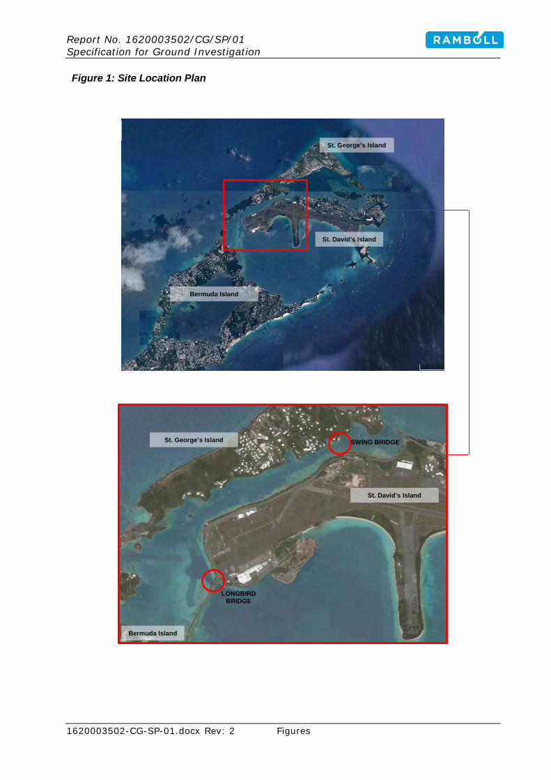
Report No. 1620003502/CG/SP/01 Specification for Ground Investigation
1620003502-CG-SP-01.docx Rev: 2 Figures
Figure 1: Site Location Plan
Bermuda Island
St. George’s Island
St. David’s Island
LONGBIRD BRIDGE
SWING BRIDGE
St. David’s Island
St. George’s Island
Bermuda Island
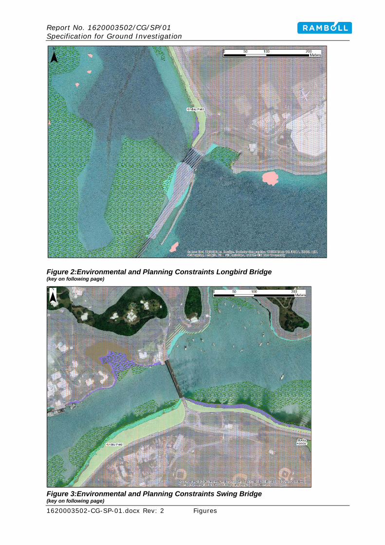
Report No. 1620003502/CG/SP/01 Specification for Ground Investigation
1620003502-CG-SP-01.docx Rev: 2 Figures
Figure 2:Environmental and Planning Constraints Longbird Bridge (key on following page)
Figure 3:Environmental and Planning Constraints Swing Bridge (key on following page)

Report No. 1620003502/CG/SP/01 Specification for Ground Investigation
1620003502-CG-SP-01.docx Rev: 2 Figures
Key for Figures 2 and 3:

Report No. 1620003502/CG/SP/01 Specification for Ground Investigation
1620003502-CG-SP-01.docx Rev: 2 Figures

Report No. 1620003502/CG/SP/01 Specification for Ground Investigation
1620003502-CG-SP-01.docx Rev: 2 Figures

Report No. 1620003502/CG/SP/01 Specification for Ground Investigation
1620003502-CG-SP-01.docx Rev: 2 Appendices
APPENDICES
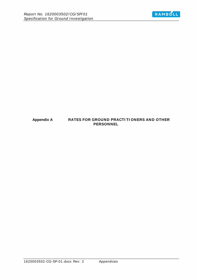
Report No. 1620003502/CG/SP/01 Specification for Ground Investigation
1620003502-CG-SP-01.docx Rev: 2 Appendices
Appendix A RATES FOR GROUND PRACTITIONERS AND OTHER PERSONNEL

Report No. 1620003502/CG/SP/01 Specification for Ground Investigation
1620003502-CG-SP-01.docx Rev: 2 Appendices
Rates shall be entered for the various grades of staff listed, who will be employed by agreement with the Investigation Supervisor to provide advice or assistance during the course of the investigation and/or the preparation of the Ground Investigation Report and/or Geotechnical Design Report all in accordance with Schedule S1.8.3
These services exclude the contract management, superintendence and technical direction require under the Conditions of Contract and the requirements of Specification Clauses 3.5.1 which are to be included in the general rates and prices of the main Bill of Quantities (see Cause 1 of the Preamble to the Bill of Quantities).
Item Item description Unit Rate 1 Technician h 2 Graduate ground engineer h 3 Experienced ground engineer h 4 Registered Ground Engineering Professional h 5 Registered Ground Engineering Specialist h 6 Registered Ground Engineering Advisor h 7 Expenses incurred by staff n site visits or who are resident
by agreement with the Investigation Supervisor day
8 Fare per kilometre 1 from Contractor’s premises and return for Items 1, 2 and 3
km 1
9 As above, but for Items 4, 5 and 6 km 1 10 All other expenses incurred in conjunction with a site visit
where a return journey is made on the same day for Items 1, 2 and 3
visit
11 As above, but for Items 4, 5 and 6 visit 12 All other expenses incurred in connection with visit where
and overnight stay is necessary for Items 1, 2 and 3 overnight
13 As above, but for Items 4, 5 and 6 overnight
1. Where considered appropriate, ‘mile’ may be used.
Estimate of costs under Appendix A to the Bill of Quantities where the provision of the Contractor’s staff for work in accordance with the following Specification Causes 3.5.2, 3.6.1 and 3.6.2 cannot be adequately specified at tender (to be assessed by the Investigation Supervisor):
$
Report No. 1620003502/CG/SP/01 Specification for Ground Investigation
1620003502-CG-SP-01.docx Rev: 2 Appendices
Appendix B LONG-TERM SAMPLE STORAGE
Report No. 1620003502/CG/SP/01 Specification for Ground Investigation
1620003502-CG-SP-01.docx Rev: 2 Appendices
Rates shall be entered for:
Item Item description Unit Rate/month Geotechnical Samples 1 Dynamic (windowless) samples nr 2 Rotary drilling core in core box nr 3 Rotary drilling core sub-samples nr 4 Bulk samples nr 5 Large bulk samples nr 6 Open-tube samples (thick-walled sampler) nr 7 Open-tube samples (thin-walled sampler) nr 8 Disturbed samples nr 9 Groundwater samples nr 10 Delft samples nr 11 Mostap samples nr 12 Piston samples nr Contamination Samples 13 Soil samples in plastic tubs nr 14 Soil samples in glass containers nr 15 Groundwater samples nr 16 Gas samples nr
Where samples comprise more than one container, the rate entered shall be per container. Estimates of costs under Appendix B to the Bill of Quantities for long term storage of samples where required in Schedules S1.12.2 and S1.12.10 (to be assessed by Investigation Supervisor):
$

Report No. 1620003502/CG/SP/01 Specification for Ground Investigation
1620003502-CG-SP-01.docx Rev: 2 Appendices
Appendix C CHEMICAL TESTING SUITES

Report No. 1620003502/CG/SP/01 Specification for Ground Investigation
1620003502-CG-SP-01.docx Rev: 2 Appendices
SCHEDULE1.20.3 CHEMICAL LABORATORY TESTING FOR CONTAMINATION Nominated test laboratory? Contractor to specify proposed laboratory
Required testing turn-around times? 10 days The Contractor shall detail the Limit of Detection, Test Method and Accreditation that can be provided for each of the determinands listed in test suites E and F. SUITE E: Soil Samples
Determinand Offered Limit of
Detection Test Method
Test Accreditation
Arsenic Cadmium Chromium (total and VI) Copper Lead Mercury Nickel Zinc pH Water soluble sulfate (as SO4)
Total Organic Carbon To be based on high temp combustion, not oxidation
Total petroleum hydrocarbons
Phenol Cyanide (total) Asbestos Tributyl tin Dibutyl tin Polyaromatic Hydrocarbons (USEPA 16)
PCBs (sum of ICES 7, sum of 25 co-geners)

Report No. 1620003502/CG/SP/01 Specification for Ground Investigation
1620003502-CG-SP-01.docx Rev: 2 Appendices
SUITE F: Water Samples
Determinand Offered Limit of
Detection Test Method
Test Accreditation
Arsenic Cadmium Chromium (total and VI) Copper Lead Mercury Nickel Zinc pH Dissolved Organic Carbon (DOC)
Total Organic Matter Total petroleum hydrocarbons
Phenol Cyanide (total) Calcium Tributyl tin Dibutyl tin Polyaromatic Hydrocarbons (USEPA 16)
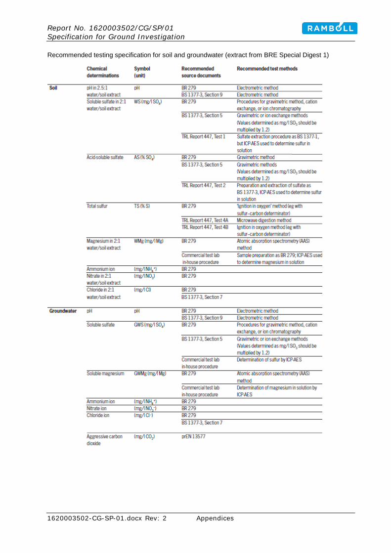
Report No. 1620003502/CG/SP/01 Specification for Ground Investigation
1620003502-CG-SP-01.docx Rev: 2 Appendices
Recommended testing specification for soil and groundwater (extract from BRE Special Digest 1)