Embed Size (px)
Citation preview
IMPI
ANTI
DI CO
NGLO
MERA
TO B
ITUMI
NOSO
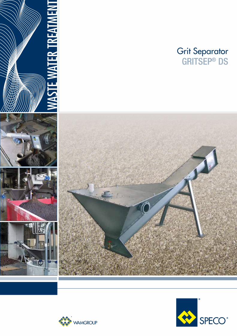
Grit Separator GRITSEP® DS
WAS
TE W
ATER
TREA
TMEN
T

The GRITSEP® Grit Separator DS consists of an inclined screw conveyor with a large volume hopper including a water inlet and outlet spout, a shaftless screw housed in a trough, a low-friction anti-wear trough liner, a trough cover, an outlet spout for solid particles, and a drive unit mounted at the outlet end.
Water to be cleaned flows through the inlet spout of the GRITSEP® Grit Separator into the sedimentation hopper where solid particles settle.
The low screw rotation speed improves sedimentation and sees to conveying and discharging of de-watered material through the upper outlet.
EFFICIENT GRIT SEPARATION
Technical Features
- Hopper manufactured from stainless steel
- Shaftless screw made up from sections of heavy-duty spiral, either in wear-resistant carbon steel or stainless steel
- Trough manufactured from stainless steel and lined with stainless steel bolted wear bars
- Liquid throughput: from 5 l/s up to 36 l/s
- Solids throughput: from 0.06 dm3/s up to 0.36 dm3/s
Grit
Sep
arat
orGR
ITSE
P® D
S
MODELFlow Rate
(m3 /h)Installed Power
kWHopper Capacity
(m3)Average Sand Extraction
(dm3/s)
DS 400 18 0.55 0.45 0,06
DS 1000 30 0.55 0.71 0,08
DS 2000 80 0.55 1.95 0,08
DS 3000 100 0.55 2.94 0,08
DS 4000 130 1.5 3.9 0,36
Settling Tank Air Injection
Safety Valve Sand Washing

Benefits
High separation performance;
Trough liner design facilitates quick and easy replacement;
Low installation and maintenance costs.
Overall Dimensions
MODEL A B C D E F G H L M PFlange1 UNI
Flange2 UNI
DS 400 * 3,710 2,020 1,450 1,995 1,390 3,365 1,215 1,490 490 1,270 650 DN80PN10 DN100PN10
DS 1000 4,490 2,170 1,460 2,330 1,290 4,000 1,830 1,400 770 1,100 685 DN100PN10 DN150PN10
DS 2000 5,480 2,580 1,850 3,215 1,650 5,00 2,396 1,805 765 1,400 980 DN125PN10 DN200PN10
DS 3000 6,485 3,015 2,320 3,180 2,038 6,015 2,410 2,190 790 1,844 1,090 DN200PN10 DN250PN10
DS 4000 6,590 3,090 2,370 3,960 2,180 6,015 2,510 2,330 865 1,985 1,140 DN400PN10 2x DN250PN10
P
G
E
A
HM
L
D
CB
INLET
F
OUTLET
1
2
For reference only: for detailed drawings please contact the Manufacturer* Transport system in tubular screw Dimensions in mm
Accessories
- Endless Tube
- Bag Clamping System

0630
0142
2
Febr
uary
2013
R
ights
rese
rved t
o mod
ify te
chni
cal s
pecif
icatio
ns.
www.wamgroup.com
Application


![[XLS]Load Reduction Estimating Workbook - Ohio …water.ohiodnr.gov/portals/soilwater/data/xls/Load... · Web viewOil/Grit Separator storm sewers. Feedlots Feedlot Pollution Reduction](https://img.dokumen.tips/doc/110x75/5b5e17937f8b9a310a8bbb8c/xlsload-reduction-estimating-workbook-ohio-water-web-viewoilgrit-separator.jpg)