Embed Size (px)
Citation preview

ARTICLE IN PRESS
0890-6955/$ - se
doi:10.1016/j.ijm
�CorrespondE-mail addr
International Journal of Machine Tools & Manufacture 47 (2007) 97–106
www.elsevier.com/locate/ijmactool
Grinding-hardening with liquid nitrogen: Mechanisms and technology
T. Nguyen, I. Zarudi, L.C. Zhang�
School of Aerospace, Mechanical and Mechatronic Engineering, The University of Sydney, NSW 2006, Australia
Received 9 January 2006; accepted 17 February 2006
Available online 11 April 2006
Abstract
This paper studies an innovative development of a steel grinding–hardening technology using an inert cryogen—liquid nitrogen.
It was found that phase transformations took place during grinding with the application of liquid nitrogen and resulted in
hardened surface layer in a ground component. The layer had a fine laths martensite structure which gave rise to a remarkably
high hardness. It was also shown that the treatment can produce superior surface integrity, with compressive surface residual
stresses and without surface oxidation. Due to the inert nature of the liquid nitrogen, the grinding process becomes environmentally
conscious.
r 2006 Elsevier Ltd. All rights reserved.
Keywords: Grinding liquid nitrogen; Microstructure; Residual stresses; Hardness; Phase transformation; Oxidation suppression
1. Introduction
Grinding–hardening treatment has attracted significantresearch attention worldwide due to its efficiency andunique properties of ground workpiece [1–7]. Relevanttheoretical and experimental studies have shown clearadvantages of grinding–hardening which combines surfaceheat treatment with surface finishing.
In the investigations on grinding-induced surface integ-rity in steel workpieces [8,9], it was found that phasetransformations during surface grinding, which in turnresulted in hardening characteristics, could be achieved bya proper selection of grinding conditions. It was also foundthat the depth and property of the martensite layer and thedistribution of residual stresses could be described quanti-tatively with respect to the material removal rate andcoolant application method.
Experimental studies also reported that the grindingenergy could be used to generate a hard surface [1,2,6].However, a hardened layer does not necessarily meanbeneficial, rather, it can be harmful if the layer is associatedwith a poor surface finish, uncontrollable precision, tensile
e front matter r 2006 Elsevier Ltd. All rights reserved.
achtools.2006.02.010
ing author. Tel.: +612 9351 2835; fax: +61 2 9351 7060.
ess: [email protected] (L.C. Zhang).
residual stresses, damaged microstructure or severe surfaceoxidation [5,6].One way to eliminate these problems is by applying new
types of coolant. It has been noticed that in the field ofwelding, oxidisation is one of the major causes inweakening the strength of welds. To overcome theproblem, nitrogen gas has been used in shielding thewelding spot [10]. On the other hand, liquid nitrogen,because of its extremely low boiling temperature, has beenwidely applied in cryogenic treatment of tool steels toconvert austenite retained from conventional quenching toa more rigid structure of martensite [11–16]. It is clear thatliquid nitrogen whilst acts as a protective shielding, canalso provide high cooling rates to promote metallurgicalchanges. However, these advantages have not beenexplored in grinding.This paper proposes an innovative development of
grinding–hardening technology using liquid nitrogen tointegrate precision surface grinding with surface hardeningtreatment, and at the same time, to produce satisfactorysurface integrity of ground components, including com-pressive surface residual stresses and fine microstructurewith high hardness. Because of the inert nature of liquidnitrogen, the grinding process becomes environmentallyconscious.

ARTICLE IN PRESS
Table 1
Chemical composition and mechanical properties of steel 1045
Chemical compositions, % Mechanical properties
C Mn P, max S, max Tensile strength (MPa) Micro-hardness (HV0.5) Yield strength (MPa)
0.42–0.50 0.60–0.90 0.040 0.050 630 172.9711.1 530
Table 2
Grinding and dressing conditions
Grinding machine Minini Junior 90 CNC-M286
Workpiece � Plain carbon steel 1045, 45� 19.5� 19.5mm
� Vacuumed pre-annealing at above 600 1C
� Initial surface residual stress: �10.0078.00MPa (longitudinal) and �10.3978.00MPa (transverse)
Grinding method Surface up grinding
Grinding wheel BWA60MVA1, f260� 20
Dressing � Single point diamond
� Transverse rate ¼ 160mm/rev
� Total dressing depth ¼ 2� 25mm
Wheel speed 23m/s
Table speed 400mm/min
Depth of cut 20mmCooling Atmospheric dry air, ambient temperature ¼ 20 1C
Liquid nitrogen, Q ¼ 2.18L/min
Noritake SA-02 (1:60), Q ¼ 18.8L/min
Fig. 1. The experimental set-up using liquid nitrogen.
T. Nguyen et al. / International Journal of Machine Tools & Manufacture 47 (2007) 97–10698
2. Experiment
The test material was widely used steel, AISI 1045,initially annealed. The chemical composition of the steel islisted in Table 1. Grinding was performed on a surface
grinder, Minini Junior 90 CF CNC M286. The grindingand dressing conditions are listed in Table 2.Fig. 1 shows the experimental set-up of surface grinding
with liquid nitrogen. The internal pressure of the reservoirwas 50 kPa, controlled by a regulator. A nozzle with the

ARTICLE IN PRESS
Fig. 2. The surface topography after grinding: (a) with coolant; (b) in the
dry air; (c) with liquid nitrogen.
0
3000
6000
Co
un
ts, a
.u.
Fe Kβ
Fe Lα
Fe Kα
C Kα
0
3000
6000
Co
un
ts, a
.u.
0
3000
6000
kV
Co
un
ts, a
.u.
0 1 2 3 64 5 7
kV0 1 2 3 64 5 7
kV0 1 2 3 64 5 7
Fe KβFe Lα
Fe Kα
O Kα
Fe Kβ
Fe Lα
Fe Kα
C Kα
C Kα
(a)
(b)
(c)
Fig. 3. EDX spectra from the ground surface after grinding: (a) with
coolant; (b) in the dry air; (c) with liquid nitrogen.
T. Nguyen et al. / International Journal of Machine Tools & Manufacture 47 (2007) 97–106 99
outlet diameter of 2mm was mounted on the wheel guardto provide a liquid jet to the grinding point from a distanceof 50mm with an angle of 301 tangential to the specimensurface. Up-grinding was used to facilitate the penetrationof liquid nitrogen into the grinding zone. After grinding, aground workpiece was left in liquid nitrogen for 600 s, andthen lifted to the ambient until its temperature reachedroom temperature.
The micro-hardness (HV) of the subsurface was exam-ined on cross-section view samples with a hardness tester,
Shimadzu Seisakusho, NT-M001. The topography ofground surfaces was observed on the scanning electronmicroscope (SEM), 505 (JEOL). Residual stresses in aground specimen were measured on an X-ray diffractionmachine, Rigaku MSF-3M. The removal of the surfacelayers in the residual stress measurement was performed onan electro-polishing machine, Movipol-3. The thicknessremoved in each step was determined on an opticalmicroscope, Leica DM RXE. The characterization of theelectron structure of the ground surfaces was done on a

ARTICLE IN PRESS
Fig. 4. Subsurface structure, hardness and residual stresses after grinding: (a) with coolant; (b) in the dry air; (c) with liquid nitrogen.
T. Nguyen et al. / International Journal of Machine Tools & Manufacture 47 (2007) 97–106100
transmission electron microscope (TEM), CM12 (Philips).TEM plan view specimens were prepared in a standardmanner using a tripod, whose thinning procedure wasperformed from the side opposite to ground surface. At thefinal stage, ion-beam thinning was used to achieve asufficiently thin area for TEM. In sample preparation, thespecimen temperature was kept below 40 1C to ensure thatno microstructural changes would take place.
3. Results and discussion
3.1. Surface topography
Fig. 2 presents the surface topography of the groundsurfaces after grinding with different cooling media.Grinding with Noritake coolant (Fig. 2(a)) has generated
continuous and shallow grooves with roughness (Ra) of
ARTICLE IN PRESS
Fig. 5. The optical micrograph: (a) grinding with coolant; (b) heat treatment; (c–d) upper part of the GIL after grinding; (c) in the dry air; (d) with liquid
nitrogen; (e–f) bottom of the GIL after grinding; (e) in the dry air; (f) with liquid nitrogen.
T. Nguyen et al. / International Journal of Machine Tools & Manufacture 47 (2007) 97–106 101
0.25 mm, confirming a ductile mode of material removal.The surface was shining and without oxidisation (Fig. 3(a)).In contrast, the ground surface obtained in dry airappeared with dark colour. The EDX spectrum showedthe oxygen peak (Fig. 3(b)), indicating a surface oxidation.In this case, the Ra roughness was 0.98 mm and it is clearthat the lack of lubrication in grinding had led todiscontinuous grooves (Fig. 2(b)). By examining thesurfaces, it was found that spherical particles appearedon the surfaces ground in dry air, which were the meltedgrinding chips [17]. It is clear that the ground surfacequality was further degraded by the ‘back-transfer’ of theworkpiece metal [18].
On the contrary, the surfaces ground with liquidnitrogen were always shining, smooth and without anysign of oxidation or burning (Figs. 2(c) and 3(c)). Theseindicate that oxidation was suppressed. Therefore, it can beconcluded that liquid nitrogen has successfully acted as aprotective shielding in grinding.
3.2. Microstructure by optical microscopy
The optical micrographs of subsurface areas aftergrinding with different coolants are presented in Figs. 4and 5.No grinding-induced layers (GILs) were admitted with
the application of Noritake coolant (Fig. 4(a)). Thestructure of material was composed of pearlite, arrangedin the background of ferrite (Fig. 5(a)).However, the GILs were found in both the components
ground in dry air or with liquid nitrogen (Figs. 4(b and c)).The GIL in a specimen ground in dry air had a variablemicrostructure of martensite (Fig. 5(c)) and a depth of350 mm. The martensite of the layer had a finer structurewhen compared with a plate-like laths martensite generatedby an ordinary heat treatment (Fig. 5(b)). At the bottomof the GIL, it was found that there existed numerousferrite grains with carbides precipitated along its bound-aries (Fig. 5(e)).
ARTICLE IN PRESS
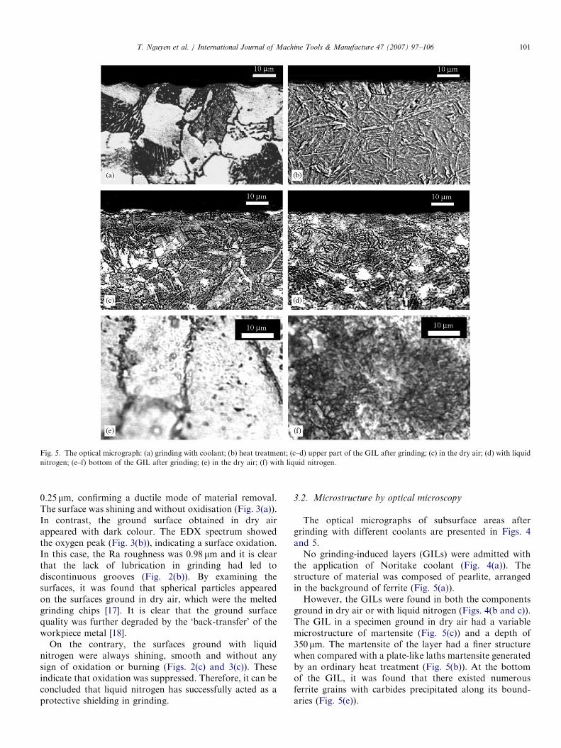
Fig. 6. The electron micrograph after grinding: (a) in the dry air; (b) with
liquid nitrogen.
T. Nguyen et al. / International Journal of Machine Tools & Manufacture 47 (2007) 97–106102
The GIL in the specimen ground with liquid nitrogenwas thinner, 85 mm in depth, but its structure was moreeven featuring martensite at the layer’s bottom (Fig. 5(e)).Martensite of the GIL near the surface was opticallyundistinguishable from the GIL after grinding in dryair (Figs. 5(c and d)). (The difference can be revealedby electron microscopy, but this will be discussed inSection 3.4.)
3.3. Micro-hardness
The micro-hardness across the thickness of a GIL can beseen in Fig. 4. It is clear that a specimen’s micro-hardnessremained unchanged (HV(500g) ¼ 200) (Fig. 4(a)) after thegrinding with Noritake coolant. However, the micro-hardness of the GIL due to the grinding in dry airincreased to HV(500g) ¼ 750 (Fig. 4(b)), which is 3.75 timeshigher than that of the original steel and 1.15 times that ofthe ordinary martensite (HV(500g) ¼ 650). There was afluctuation of the micro-hardness across the GIL, whichdecreased to HV(500g) ¼ 400 at the layer’s bottom, becausethe microstructure changed to the ferrite–carbide arrange-ment. It was very promising that the micro-hardness of theGIL generated by the grinding with liquid nitrogen waseven higher, HV(500g) ¼ 1100 (Fig. 4(c)), which is 1.46 timeshigher than that of the GIL developed by the grinding indry air. Furthermore, the micro-hardness decreased onlyslightly across the GIL thickness, which was stillHV(500g) ¼ 700 at the layer’s bottom due to even martensitestructure (Fig. 5(e)).
3.4. Microstructure revealed by electron microscopy
The microstructure of the upper part of the GIL (nearthe specimen’s surface) induced by the grinding in dry air isshown in Fig. 6(a). The martensite laths are grouped inpackets. The martensite crystals inside a packet areelongated in approximately the same direction, with anaverage length of 2–4 mm and an average width of0.3–0.5 mm. The dislocation density is high. Dispersedprecipitations with characteristic dimension of 20–50 nmwere easily located at boundaries (Fig. 7(a)) and inside thelaths (Fig. 7(c)). A diffraction analysis showed that they areinterstitial carbides of two types, x-carbide Fe2.4C withhexagonal structure or Z-carbide Fe2C with orthorhombicstructure [19]. Figs. 7(a and b) present the bright and darkimages of x-carbide and diffraction pattern with zone axis½1̄ 1̄ 1� of Fe2.4C J to [1 1 1] of martensite. Z-carbide ispresented in Figs. 7(c and d), with zone axis ½1̄ 1 1̄� of Fe2CJ to [3 3 1] of martensite.
The upper part of the GIL obtained with liquid nitro-gen was composed of fine and nearly circular grainswith a characteristic dimension of 0.2–0.3 mm. More-over, the dislocation structure of the martensite frag-ments was mainly cellular, although polygonal regionsoccasionally appeared (Fig. 6(b)). No carbides wereobserved.
3.5. Residual stresses
The distributions of residual stresses in subsurface ofground components are shown in Fig. 4. In this figure, sxx
and syy are residual stresses measured along and perpendi-cular to the grinding direction, respectively.Grinding with Noritake coolant produces compressive
residual stresses of 200–400MPa to the depth of 100 mmin the ground component for both measured directions(Fig. 4(a)).On the contrary, grinding in dry air created tensile
residual stresses of 100–200MPa along the whole depth ofthe GIL (400 mm) in both xx and yy directions (Fig. 4(b)),which is not desirable in engineering applications becausetensile surface residual stresses facilitate fracture, fatiguefailure, corrosion and wear.The application of liquid nitrogen created compressive
residual stresses of 200MPa, spreading to the depth of85 mm (Fig. 4(c)), which is similar to those produced by thegrinding with coolant. The origin of these advantages willbe discusses below.

ARTICLE IN PRESS
Fig. 7. The electron micrograph of interstitial carbides after grinding in the dry air: (a) the bright field and the indexed diffraction pattern (Note e-carbidesat laths boundary); (b) the dark field in the 101 Fe2.4C reflection; (c) the bright field and the indexed diffraction pattern (Note Z-carbides inside martensite
laths); (d) the dark field in the 0 0 1̄ Fe2C reflection.
T. Nguyen et al. / International Journal of Machine Tools & Manufacture 47 (2007) 97–106 103
3.6. Mechanisms of heating, microstructure and residual
stress development
The above results show that liquid nitrogen is a superiorcooling medium for a grinding-hardening operation. Itsapplication not only enhances the mechanical properties ofa ground component and creates compressive residualstresses, but also eliminates surface oxidation. To achieve adeeper understanding, it is necessary to look into theheating mechanism that took place within the wheel–workpiece interaction zone and the development ofthe GIL microstructure and residual stresses duringgrinding.
In a grinding–hardening process, the development of theGIL is the result of phase transformations during which thesteel is heated above Ac3. As the thickness of a martensitelayer is known, which can be measured from Fig. 4, thesurface temperature in grinding can be approximatelyestimated by [17]
Ac3
ys¼ 1� erf y
,2
k
rC
ðDdÞ1=2
vw
!1=224
35
8<:
9=;,
where Ac3 is the austenite transition temperature which is795 1C for the 1045 steel used in this study, y is the
thickness of the martensitic layer, erf is the Gaussian errorfunction, k/rC is the thermal diffusivity, D is the wheeldiameter, d is the depth of cut and vw is the table speed.This formula predicts that the mean surface temperature,ys, should be 833 and 1023 1C, for grinding with liquidnitrogen and dry air, respectively. While such a hightemperature rise in dry air is not surprising, the followingdiscussion and experimental observation can explain howthe large temperature rise occurred even with the applica-tion of liquid nitrogen whose boiling temperature is�196 1C.It is well known that heating in grinding is localised
within a very small grinding zone and the degree ofgrinding-heating depends on the quantity of the coolingmedium penetrated into the zone [20]. As illustrated inFig. 8(a), when liquid nitrogen is applied, its highevaporation rate is further raised by the turbulent air flowgenerated by wheel rotation. As a result, the penetration ofliquid nitrogen into the grinding zone is extremely limited,leaving the wheel pores and workpiece in contact with onlya little amount of nitrogen gas, as illustrated in the figure.Heat dissipation due to the boiling of liquid nitrogen iseffective only in the vicinity of the grinding zone. Hence, ahigh temperature rise takes place inside the grinding zone.This mechanism is well demonstrated by the experiment

ARTICLE IN PRESS
Fig. 8. Nitrogen penetration in the grinding zone: (a) schematic presentation; (b) general view (Note an extensive evaporation of nitrogen).
T. Nguyen et al. / International Journal of Machine Tools & Manufacture 47 (2007) 97–106104
shown in Fig. 8(b), where significant amount of liquidnitrogen vapour appeared.
Now let us consider the microstructure development ingrinding–harderning. As mentioned before, to initiate theGIL, it is necessary to bring the temperature above Ac3.According to our estimation previously, the grinding withliquid nitrogen met the condition. Moreover, the applica-tion of liquid nitrogen increased the cooling rate, so thatthe heat treatment cycle became different from the grindingin air or coolant (Fig. 9). Hence, the deformation ofaustenite during the grinding with liquid nitrogen occurredat a lower temperature and promoted the development ofcellular and polygonal dislocation structures. The sub-structure generated in the austenite prevented the growthof martensite crystals, facilitated an increase in the numberof nucleation centres, and caused the overall refinement ofthe martensite structure. Because of that, the martensiteinduced by the grinding with liquid nitrogen had a muchfiner structure (Fig. 6(b)).
The change in the cooling rate also affected the final GILstructure. The nose of the Bs curve in the TTT diagram of1045 carbon steel is located at 540 1C and is at 1 s [21]. Itmeans that to avoid carbide precipitation the cooling ratemust be above 500 grad/s for the grinding in dry air and250 grad/s for that in liquid nitrogen. As the dry air-grinding failed to meet the condition, carbides were easilyformed in the GIL (Fig. 7). Furthermore, the high strainrate in grinding changed the kinetics of their precipitationand endorsed the development of interstitial e and Zcarbides. In the grinding with liquid nitrogen, however, thecooling rate was well above 250 grad/s. Hence, no carbidesappeared.Clearly, the GIL created by the grinding with liquid
nitrogen is very advantageous due to the refinement ofmartensite and absence of carbides—both increase thehardness of the GIL.Now let us consider the development of residual
stresses. Relevant studies on residual stresses in a ground

ARTICLE IN PRESS
Fig. 9. Thermal cycles in grinding.
T. Nguyen et al. / International Journal of Machine Tools & Manufacture 47 (2007) 97–106 105
component have concluded that their creation is due tomechanical traction, thermal deformation and phasetransformation [22]. The mechanical traction generallyproduces compressive stresses. The thermal deformation,however, often leads to tensile stresses. When phasetransformation occurs, additional residual stresses appear,which can alter the resultant stress distribution [9,23,24]—either tensile or compressive, depending on the volumechanges of the new phases. In the case of martensitetransformation, compressive residual stresses arise as itsbody-centered tetragonal (BCT) lattice occupies morespace than the original body-centered cubic (BCC) latticeof ferrite accomplished with orthorhombic lattice ofcementite [21].
The tensile stresses generated by the grinding with dry airwere due to the development of high heat (the temperaturerise was 1023 1C as calculated before). At the same time,the precipitation of interstitial carbides Fe2C and Fe2.4Clowered the volume of BCT martensite lattice and reducedthe compressive stresses caused by phase transformation,leading to tensile resultant stresses.
In the grinding with liquid nitrogen, the smallertemperature rise (833 1C), fine homogeneous martensitestructure (absence of carbides), and high mechanicaltraction all contributed to the generation of compressiveresultant residual stresses.
4. Conclusions
This paper has presented an innovative development of asteel grinding–hardening technology using liquid nitrogen.The major conclusions are as follows:
1.
The treatment can produce satisfactory surface integrity,including the compressive surface residual stresses andoxidation-free surface finish.2.
The phase transformations took place during grindingresulted in a martensite layer in a ground component.The layer had a fine martensite structure which gives riseto a remarkably high hardness.
3.
The grinding with liquid nitrogen is environmentallyconscious.References
[1] E. Brinksmeier, T. Brockhoff, Utilization of grinding heat as a new
heat treatment process, Annals of the CIRP 45 (1996) 283–286.
[2] T. Brockhoff, Grind-hardening: a comprehensive view, Annals of the
CIRP 48 (1999) 255–260.
[3] S. Malkin, Burning limit for surface and cylindrical grinding of steels,
Annals of the CIRP 27 (1978) 233–236.
[4] M.C. Shaw, A. Vyas, Heat-affected zones in grinding steel, Annals of
the CIRP 43 (1994) 279–282.
[5] I. Zarudi, L.C. Zhang, A revisit to some wheel–workpiece interaction
problems in surface grinding, International Journal of Machine Tools
and Manufacture 42 (8) (2002) 905–913.
[6] I. Zarudi, L.C. Zhang, Mechanical property improvement of
quenchable steel by grinding, Journal of Materials Science 37 (18)
(2002) 3935–3943.
[7] I. Zarudi, L.C. Zhang, Modelling the structure changes in quenchable
steel subjected to grinding, Journal of Materials Science 37 (2) (2002)
4333–4341.
[8] M. Mahdi, L.C. Zhang, Applied mechanics in grinding, part VII:
residual stresses induced by the full coupling of mechanical
deformation, thermal deformation and phase transformation, Inter-
national Journal of Machine Tools & Manufacture 39 (1999)
1285–1298.
[9] M. Mahdi, L. Zhang, Applied mechanics in grinding—VI. Residual
stresses and surface hardening by coupled thermo-plasticity and
phase transformation, International Journal of Machine Tools &
Manufacture 38 (1998) 1289–1304.
[10] G.E. Linnert, Welding Metallurgy, Carbon and Alloy Steel, vol 1,
American welding society, Miami, FL, USA, 1994.
[11] P. Cohen, D. Kamody, Cryogenics goes deeper, Cutting Tool
Engineering 50 (1998) 1–3.
[12] P. Gorden, C.M., The transformation of retained austenite in
high speed steel at subatmospheric temperatures, Transactions of
American Society for Metals 30 (1942) 569–591.
[13] J.R. Kennedy, A study of subzero treatments applied to Molybde-
num–Tungsten high speed steel, Transactions of American Society
for Metals 34 (1945) 251–309.

ARTICLE IN PRESST. Nguyen et al. / International Journal of Machine Tools & Manufacture 47 (2007) 97–106106
[14] F. Meng, K. Tagashira, R. Azuma, Role of Eta-carbide precipitation
in the wear resistance improvements of Fe–12Cr–Mo–V–1.4C tool
steel by cryogenic treatment, ISIJ International 34 (1994) 205–210.
[15] E.S. Zhmud, Improved tool life after shock cooling, Metals Science
and Heat Treatment 10 (1980) 701–703.
[16] K. Nagai, T. Yuri, T. Ogata, O. Umezawa, K. Ishikawa, T.
Nishimura, Cryogenic mechanical properties of Ti–6Al–4V alloys
with three levels of oxygen content, ISIJ International 31 (1991)
882–889.
[17] M.C. Shaw, Principles of Abrasive Processing, University Press,
Oxford, 1996, pp. 574.
[18] S. Malkin, Grinding Technology—Theory and Applications of Machin-
ing with Abrasives, EllisHorwood Ltd, Chichester, 1989, pp. 275.
[19] A. Koniger, C. Hammerl, M. Zeitler, B. Rauschenbach, Formation
of metastable iron carbide phases after high-fluence carbon ions
implantation into iron at low temperatures, Physical Review B 55 (13)
(1997) 8143–8147.
[20] A.S. Lavine, T.C. Jen, Thermal aspects of grinding: heat transfer to
workpiece, wheel, and fluid, Transactions of the ASME 113 (1991)
296–303.
[21] G. Krauss, Steels: Principles of Heat Treatment of Steels, ASM
International, Metals Park, OH, 1980.
[22] L.C. Zhang, T. Suto, H. Noguchi, T. Waida, A study of creep-feed
grinding of metallic and ceramic materials, Journal of Materials
Processing Technology 48 (1995) 267–274.
[23] L.C. Zhang, T. Suto, H. Noguchi, T. Waida, An overview of applied
mechanics in grinding, Manufacturing Review 5 (1992) 261–273.
[24] M. Mahdi, L.C. Zhang, Applied mechanics in grinding-V. Thermal
residual stresses, International Journal of Machine Tools &
Manufacture 37 (1997) 619–633.