Embed Size (px)
Citation preview

40th Annual Conference of the Canadian Nuclear Society and 45th Annual CNS/CNA Student Conference
GRIDRESERVE, TECHNICAL FEASIBILITY AND ECONOMICS OF A HYBRID SMALL MODULAR REACTOR AND THERMAL ENERGY
STORAGE TO ENABLE NUCLEAR AS PEAKING PLANT
J. Soravilla1, S. Martínez2, O. Larrosa3, D. Taylor4, G. Anderson5, R. O’Sullivan6 1 IDOM Consulting, Engineering, Architecture SAU, Barcelona, Cataluña, Spain 2 IDOM Consulting, Engineering, Architecture SAU, Barcelona, Cataluña, Spain
3 IDOM Consulting, Engineering, Architecture SAU, Madrid, Madrid, Spain
4 NB Power, Saint John, New Brunswick, Canada
5 Moltex Energy Ltd., Stratford-upon-Avon, Warwickshire, United Kingdom
6 Moltex Energy Canada Inc., Saint John, New Brunswick, Canada
[email protected], [email protected], [email protected], [email protected],
[email protected], [email protected]
Abstract
Internationally, concern has grown over the lack of effectiveness of energy solutions to fight climate change. The most common approach to date involves the deployment of intermittent renewable energy sources and gas as a back-up. This paper presents the technical feasibility and economics of GridReserve® thermal energy storage used in combination with the Stable Salt Reactor (SSR). GridReserve® enables gigawatt-hours of thermal storage so electricity can be generated during sustained periods of no wind or sunshine. Installed capacity costs can be as a low as a gas fired power plant, which could ultimately lower the total ‘all up’ costs of renewables and reduce rate payer bills. Where most Small Modular Reactors (SMR) reduce power output to provide flexible electricity, GridReserve® allows the SSR to continue running at full power while putting several times more power onto the grid for shorter durations.
1. Introduction
GridReserve® is Moltex’s (https://www.moltexenergy.com/) solution to enabling a nuclear and renewables powered electrical grid.
Energy storage is not considered economically feasible at the low operating temperatures of current pressurized water reactors (~300°C), making it difficult to integrate into grids with low demand or high variable demand profiles. GridReserve® can store thermal energy from the SSR and convert it to electrical energy for delivery to the grid during peak demand periods. This stored thermal energy can be used to complement the intermittent, unpredictable and inflexible operational nature of renewables.
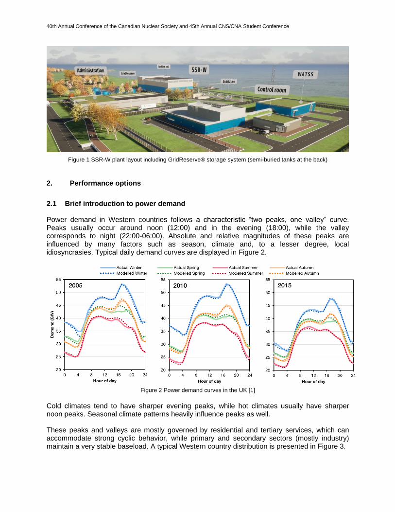
Moltex’s GridReserve® system consists of a group of insulated tanks filled with a molten salt mixture capable of storing thermal energy. The mixture is made up of sodium and potassium nitrates, and is similar to that used in concentrated solar power (CSP) plants. Heat generated from Moltex’s 300MW Stable Salt Reactor – Wasteburner (SSR-W300) can be retained in the storage system for about 8-10h at temperatures of about 550°C. A layout of the SSR-W plant can be observed in Figure 1.
40th Annual Conference of the Canadian Nuclear Society and 45th Annual CNS/CNA Student Conference
Figure 1 SSR-W plant layout including GridReserve® storage system (semi-buried tanks at the back)
2. Performance options
2.1 Brief introduction to power demand
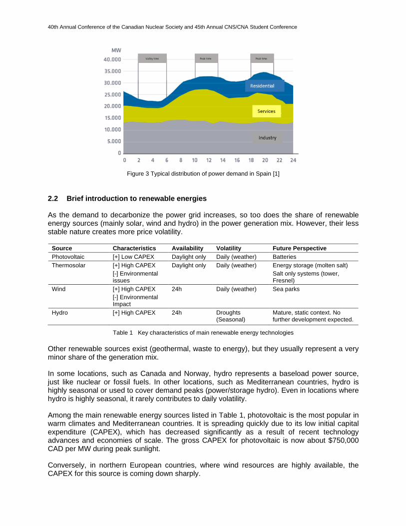
Power demand in Western countries follows a characteristic “two peaks, one valley” curve. Peaks usually occur around noon (12:00) and in the evening (18:00), while the valley corresponds to night (22:00-06:00). Absolute and relative magnitudes of these peaks are influenced by many factors such as season, climate and, to a lesser degree, local idiosyncrasies. Typical daily demand curves are displayed in Figure 2.
Figure 2 Power demand curves in the UK [1]
Cold climates tend to have sharper evening peaks, while hot climates usually have sharper noon peaks. Seasonal climate patterns heavily influence peaks as well.
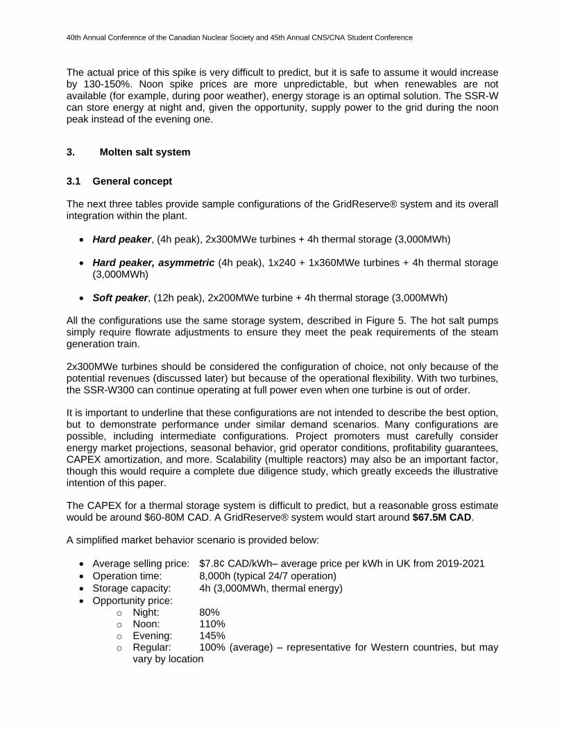
These peaks and valleys are mostly governed by residential and tertiary services, which can accommodate strong cyclic behavior, while primary and secondary sectors (mostly industry) maintain a very stable baseload. A typical Western country distribution is presented in Figure 3.
40th Annual Conference of the Canadian Nuclear Society and 45th Annual CNS/CNA Student Conference
Figure 3 Typical distribution of power demand in Spain [1]
2.2 Brief introduction to renewable energies
As the demand to decarbonize the power grid increases, so too does the share of renewable energy sources (mainly solar, wind and hydro) in the power generation mix. However, their less stable nature creates more price volatility.
Source Characteristics Availability Volatility Future Perspective
Photovoltaic [+] Low CAPEX Daylight only Daily (weather) Batteries
Thermosolar [+] High CAPEX
[-] Environmental issues
Daylight only Daily (weather) Energy storage (molten salt)
Salt only systems (tower, Fresnel)
Wind [+] High CAPEX
[-] Environmental Impact
24h Daily (weather) Sea parks
Hydro [+] High CAPEX
24h Droughts (Seasonal)
Mature, static context. No further development expected.
Table 1 Key characteristics of main renewable energy technologies Other renewable sources exist (geothermal, waste to energy), but they usually represent a very minor share of the generation mix.
In some locations, such as Canada and Norway, hydro represents a baseload power source, just like nuclear or fossil fuels. In other locations, such as Mediterranean countries, hydro is highly seasonal or used to cover demand peaks (power/storage hydro). Even in locations where hydro is highly seasonal, it rarely contributes to daily volatility.
Among the main renewable energy sources listed in Table 1, photovoltaic is the most popular in warm climates and Mediterranean countries. It is spreading quickly due to its low initial capital expenditure (CAPEX), which has decreased significantly as a result of recent technology advances and economies of scale. The gross CAPEX for photovoltaic is now about $750,000 CAD per MW during peak sunlight.
Conversely, in northern European countries, where wind resources are highly available, the CAPEX for this source is coming down sharply.

40th Annual Conference of the Canadian Nuclear Society and 45th Annual CNS/CNA Student Conference
Battery storage is still in its early stages and mostly geared towards photovoltaic energy. However, recent studies are also looking at the possibility of using them as a universal storage solution for any power source.
2.3 Brief introduction to price behaviour
The price behavior of the kilowatt-hour (kWh) in the market is dependent on multiple factors. Among other things, it is heavily influenced by the power generation mix and the power exporting capabilities of neighboring countries/jurisdictions.
A common factor in locations with a rich mix of renewable energy sources is high price volatility, mainly because of the mismatch between renewable generation, which is heavily influenced by seasonal and weather conditions, and power demand, which is more stable. This often leads to oversized generation stations, which can easily produce excess power under optimal conditions (sunny days across the region, high winds, etc.).
The result is high price volatility on a day-to-day basis. Meanwhile, hourly prices tend to be more stable, as renewable power stations (mostly solar) disconnect at night, leaving baseload power stations to support the (mostly) industrial demand.
Conversely, locations relying heavily on baseload energy sources (fossil fuels, nuclear, hydro) tend to have more predictable daily and hourly prices, but sharper contrasts in those prices, due to the higher cost of underperforming baseload generation at night.
Figure 4 Energy SPOT prices (€/MWh) in Spain (red) and France (blue) on July 3, 2020 [1] Figure 4 illustrates the typical behavior of a baseload rich country (France) and a renewable rich country (Spain). In France, a country that relies on nuclear as a baseload energy source, the hourly prices vary more dramatically between day and night. A case-by-case analysis shall be done for each location.
Another analysis (https://www.esios.ree.es/en) shows the average market price in the UK from 2019-2021 was $7.8¢ CAD/kWh.
In all the above cases, price spikes occur during the noon and evening demand peaks. Jurisdictions dominated by renewables can easily handle the noon price spike, which is around solar peak hours, but fail to properly address the evening spike. This poorly covered spike is what leads to the very common size of most thermal storage systems (3-4h).
40th Annual Conference of the Canadian Nuclear Society and 45th Annual CNS/CNA Student Conference
The actual price of this spike is very difficult to predict, but it is safe to assume it would increase by 130-150%. Noon spike prices are more unpredictable, but when renewables are not available (for example, during poor weather), energy storage is an optimal solution. The SSR-W can store energy at night and, given the opportunity, supply power to the grid during the noon peak instead of the evening one.
3. Molten salt system
3.1 General concept
The next three tables provide sample configurations of the GridReserve® system and its overall integration within the plant.
• Hard peaker, (4h peak), 2x300MWe turbines + 4h thermal storage (3,000MWh)
• Hard peaker, asymmetric (4h peak), 1x240 + 1x360MWe turbines + 4h thermal storage (3,000MWh)
• Soft peaker, (12h peak), 2x200MWe turbine + 4h thermal storage (3,000MWh)
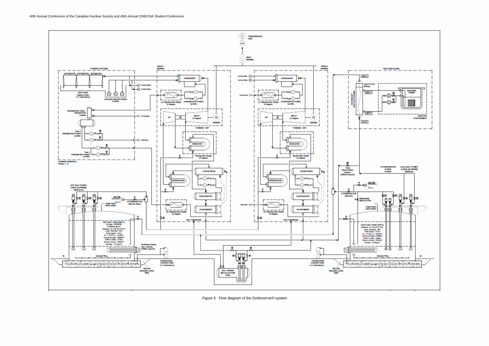
All the configurations use the same storage system, described in Figure 5. The hot salt pumps simply require flowrate adjustments to ensure they meet the peak requirements of the steam generation train.
2x300MWe turbines should be considered the configuration of choice, not only because of the potential revenues (discussed later) but because of the operational flexibility. With two turbines, the SSR-W300 can continue operating at full power even when one turbine is out of order.
It is important to underline that these configurations are not intended to describe the best option, but to demonstrate performance under similar demand scenarios. Many configurations are possible, including intermediate configurations. Project promoters must carefully consider energy market projections, seasonal behavior, grid operator conditions, profitability guarantees, CAPEX amortization, and more. Scalability (multiple reactors) may also be an important factor, though this would require a complete due diligence study, which greatly exceeds the illustrative intention of this paper.
The CAPEX for a thermal storage system is difficult to predict, but a reasonable gross estimate would be around $60-80M CAD. A GridReserve® system would start around $67.5M CAD.
A simplified market behavior scenario is provided below:
• Average selling price: $7.8¢ CAD/kWh– average price per kWh in UK from 2019-2021
• Operation time: 8,000h (typical 24/7 operation)
• Storage capacity: 4h (3,000MWh, thermal energy)
• Opportunity price: o Night: 80% o Noon: 110% o Evening: 145% o Regular: 100% (average) – representative for Western countries, but may
vary by location
40th Annual Conference of the Canadian Nuclear Society and 45th Annual CNS/CNA Student Conference
Figure 5 Flow diagram of the Gridreserve® system
40th Annual Conference of the Canadian Nuclear Society and 45th Annual CNS/CNA Student Conference
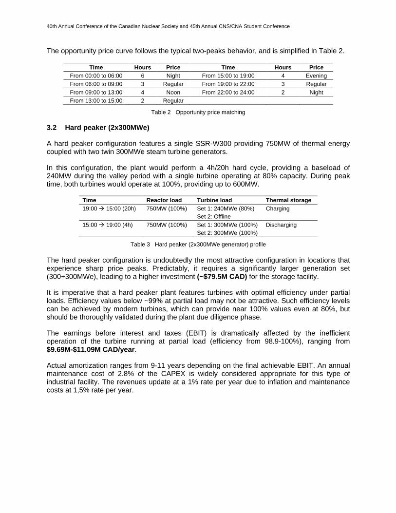
The opportunity price curve follows the typical two-peaks behavior, and is simplified in Table 2.
Time Hours Price Time Hours Price
From 00:00 to 06:00 6 Night From 15:00 to 19:00 4 Evening
From 06:00 to 09:00 3 Regular From 19:00 to 22:00 3 Regular
From 09:00 to 13:00 4 Noon From 22:00 to 24:00 2 Night
From 13:00 to 15:00 2 Regular
Table 2 Opportunity price matching
3.2 Hard peaker (2x300MWe)
A hard peaker configuration features a single SSR-W300 providing 750MW of thermal energy coupled with two twin 300MWe steam turbine generators.
In this configuration, the plant would perform a 4h/20h hard cycle, providing a baseload of 240MW during the valley period with a single turbine operating at 80% capacity. During peak time, both turbines would operate at 100%, providing up to 600MW.
Time Reactor load Turbine load Thermal storage
19:00 → 15:00 (20h) 750MW (100%) Set 1: 240MWe (80%)
Set 2: Offline
Charging
15:00 → 19:00 (4h) 750MW (100%) Set 1: 300MWe (100%)
Set 2: 300MWe (100%)
Discharging
Table 3 Hard peaker (2x300MWe generator) profile
The hard peaker configuration is undoubtedly the most attractive configuration in locations that experience sharp price peaks. Predictably, it requires a significantly larger generation set (300+300MWe), leading to a higher investment (~$79.5M CAD) for the storage facility.
It is imperative that a hard peaker plant features turbines with optimal efficiency under partial loads. Efficiency values below ~99% at partial load may not be attractive. Such efficiency levels can be achieved by modern turbines, which can provide near 100% values even at 80%, but should be thoroughly validated during the plant due diligence phase.
The earnings before interest and taxes (EBIT) is dramatically affected by the inefficient operation of the turbine running at partial load (efficiency from 98.9-100%), ranging from $9.69M-$11.09M CAD/year.
Actual amortization ranges from 9-11 years depending on the final achievable EBIT. An annual maintenance cost of 2.8% of the CAPEX is widely considered appropriate for this type of industrial facility. The revenues update at a 1% rate per year due to inflation and maintenance costs at 1,5% rate per year.
40th Annual Conference of the Canadian Nuclear Society and 45th Annual CNS/CNA Student Conference
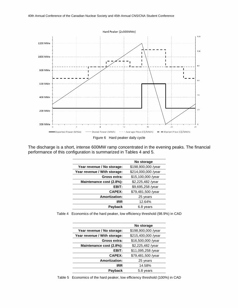
Figure 6 Hard peaker daily cycle
The discharge is a short, intense 600MW ramp concentrated in the evening peaks. The financial performance of this configuration is summarized in Tables 4 and 5.
No storage
Year revenue / No storage: $198,900,000 /year
Year revenue / With storage: $214,000,000 /year
Gross extra: $15,100,000 /year
Maintenance cost (2.8%): $2,225,482 /year
EBIT: $9,695,258 /year
CAPEX: $79,481,500 /year
Amortization: 25 years
IRR 12.64%
Payback 6.8 years
Table 4 Economics of the hard peaker, low efficiency threshold (98.9%) in CAD
No storage
Year revenue / No storage: $198,900,000 /year
Year revenue / With storage: $215,400,000 /year
Gross extra: $16,500,000 /year
Maintenance cost (2.8%): $2,225,482 /year
EBIT: $11,095,258 /year
CAPEX: $79,481,500 /year
Amortization: 25 years
IRR 14.58%
Payback 5.8 years
Table 5 Economics of the hard peaker, low efficiency threshold (100%) in CAD
40th Annual Conference of the Canadian Nuclear Society and 45th Annual CNS/CNA Student Conference
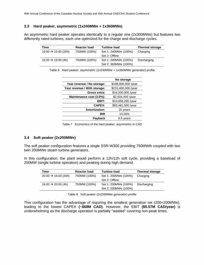
3.3 Hard peaker, asymmetric (1x240MWe + 1x360MWe)
An asymmetric hard peaker operates identically to a regular one (2x300MWe) but features two differently rated turbines, each one optimized for the charge and discharge cycles.
Time Reactor load Turbine load Thermal storage
19:00 → 15:00 (20h) 750MW (100%) Set 1: 240MWe (100%)
Set 2: Offline
Charging
15:00 → 19:00 (4h) 750MW (100%) Set 1: 240MWe (100%)
Set 2: 360MWe (100%)
Discharging
Table 6 Hard peaker, asymmetric (1x240MWe + 1x360MWe generator) profile
No storage
Year revenue / No storage: $198,900,000 /year
Year revenue / With storage: $215,400,000 /year
Gross extra: $16,500,000 /year
Maintenance cost (3.0%): $2,504,445 /year
EBIT: $10,656,295 /year
CAPEX: $83,481,500 /year
Amortization: 25 years
IRR 13.26%
Payback 6.5 years
Table 7 Economics of the hard peaker, asymmetric in CAD
3.4 Soft peaker (2x200MWe)
The soft peaker configuration features a single SSR-W300 providing 750MWth coupled with two twin 200MWe steam turbine generators.
In this configuration, the plant would perform a 12h/12h soft cycle, providing a baseload of 200MW (single turbine operation) and peaking during high demand.
Time Reactor load Turbine load Thermal storage
20:00 → 16:00 (20h) 750MW (100%) Set 1: 200MWe (100%)
Set 2: Offline
Charging
16:00 → 20:00 (4h) 750MW (100%) Set 1: 200MWe (100%)
Set 2: 200MWe (100%)
Discharging
Table 8 Soft peaker (2x200MWe generator) profile
This configuration has the advantage of requiring the smallest generation set (200+200MWe), leading to the lowest CAPEX (~$68M CAD). However, the EBIT ($5.57M CAD/year) is underwhelming as the discharge operation is partially “wasted” covering non-peak times.
40th Annual Conference of the Canadian Nuclear Society and 45th Annual CNS/CNA Student Conference
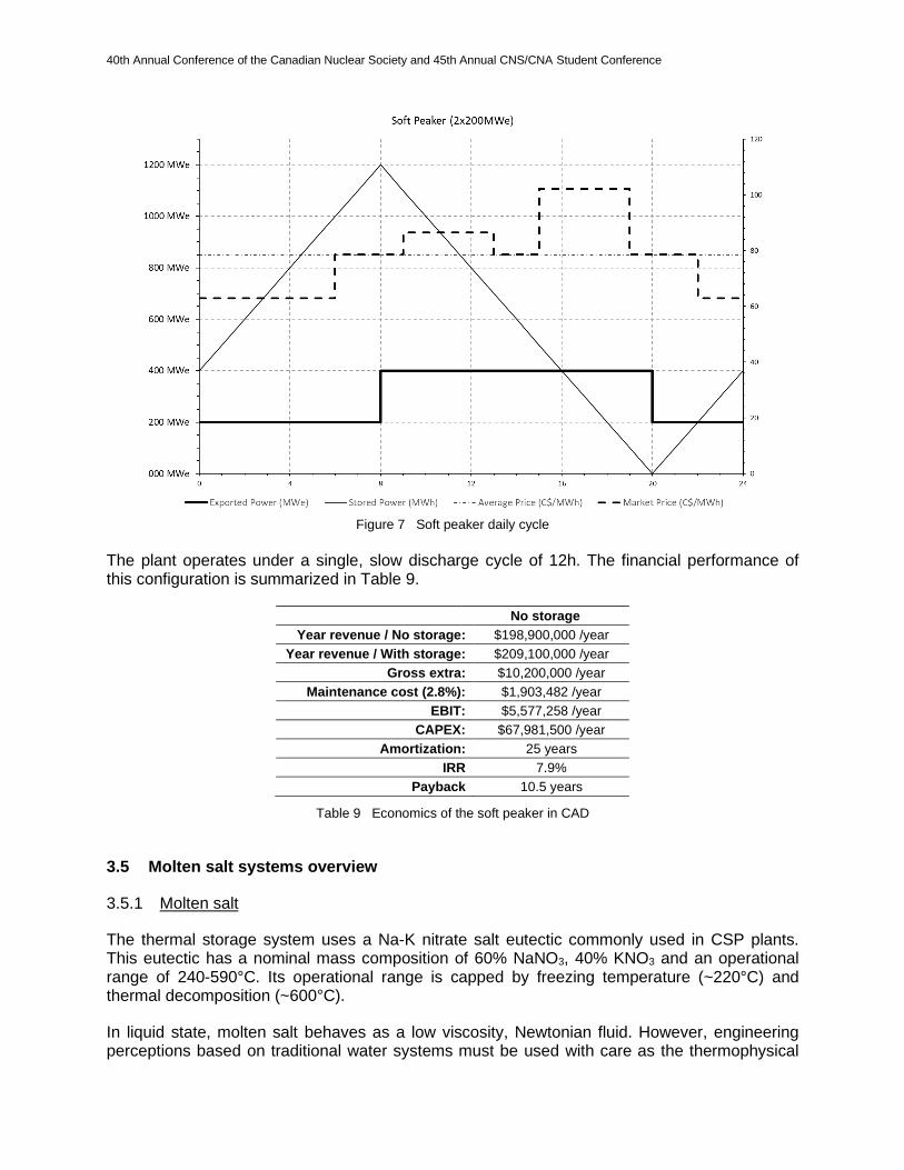
Figure 7 Soft peaker daily cycle
The plant operates under a single, slow discharge cycle of 12h. The financial performance of this configuration is summarized in Table 9.
No storage
Year revenue / No storage: $198,900,000 /year
Year revenue / With storage: $209,100,000 /year
Gross extra: $10,200,000 /year
Maintenance cost (2.8%): $1,903,482 /year
EBIT: $5,577,258 /year
CAPEX: $67,981,500 /year
Amortization: 25 years
IRR 7.9%
Payback 10.5 years
Table 9 Economics of the soft peaker in CAD
3.5 Molten salt systems overview
3.5.1 Molten salt
The thermal storage system uses a Na-K nitrate salt eutectic commonly used in CSP plants. This eutectic has a nominal mass composition of 60% NaNO3, 40% KNO3 and an operational range of 240-590°C. Its operational range is capped by freezing temperature (~220°C) and thermal decomposition (~600°C).
In liquid state, molten salt behaves as a low viscosity, Newtonian fluid. However, engineering perceptions based on traditional water systems must be used with care as the thermophysical
40th Annual Conference of the Canadian Nuclear Society and 45th Annual CNS/CNA Student Conference
properties of salt is different. In particular, density is twice that of water systems, and can therefore be misleading when expressed in fluid head (meters).
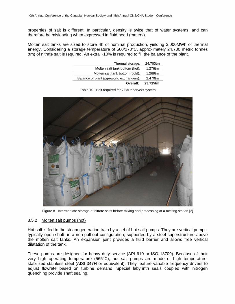
Molten salt tanks are sized to store 4h of nominal production, yielding 3,000MWh of thermal energy. Considering a storage temperature of 560/270°C, approximately 24,700 metric tonnes (tm) of nitrate salt is required. An extra ~10% is required to fill the balance of the plant.
Thermal storage: 24,700tm
Molten salt tank bottom (hot): 1,276tm
Molten salt tank bottom (cold): 1,269tm
Balance of plant (pipework, exchangers): 2,470tm
Overall: 29,715tm
Table 10 Salt required for GridReserve® system
Figure 8 Intermediate storage of nitrate salts before mixing and processing at a melting station [3]
3.5.2 Molten salt pumps (hot)
Hot salt is fed to the steam generation train by a set of hot salt pumps. They are vertical pumps, typically open-shaft, in a non-pull-out configuration, supported by a steel superstructure above the molten salt tanks. An expansion joint provides a fluid barrier and allows free vertical dilatation of the tank.
These pumps are designed for heavy duty service (API 610 or ISO 13709). Because of their very high operating temperature (565°C), hot salt pumps are made of high temperature, stabilized stainless steel (AISI 347H or equivalent). They feature variable frequency drivers to adjust flowrate based on turbine demand. Special labyrinth seals coupled with nitrogen quenching provide shaft sealing.
40th Annual Conference of the Canadian Nuclear Society and 45th Annual CNS/CNA Student Conference
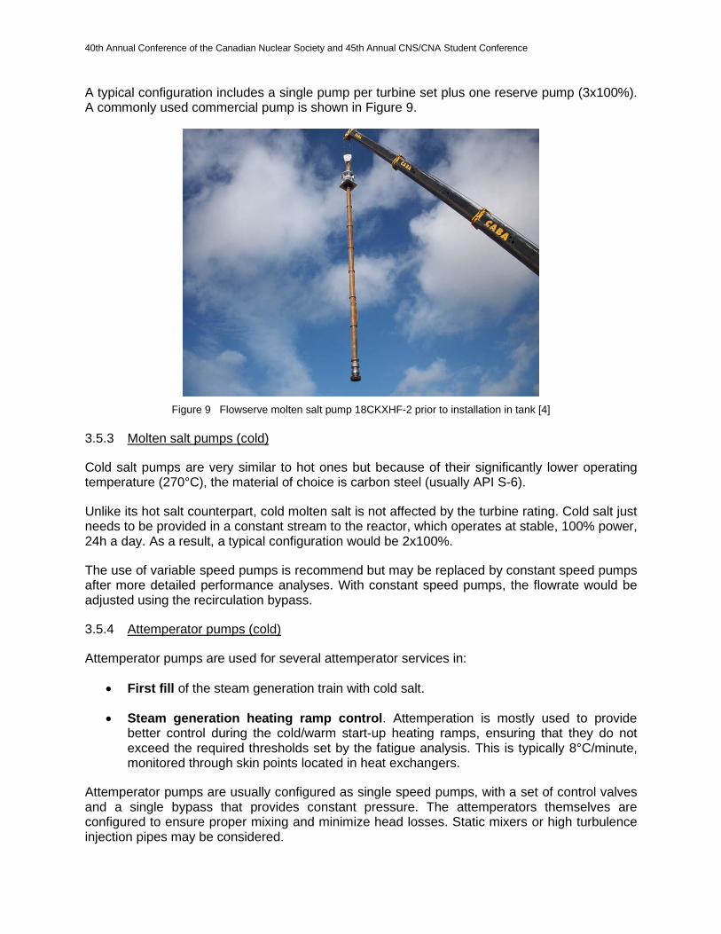
A typical configuration includes a single pump per turbine set plus one reserve pump (3x100%). A commonly used commercial pump is shown in Figure 9.
Figure 9 Flowserve molten salt pump 18CKXHF-2 prior to installation in tank [4]
3.5.3 Molten salt pumps (cold)
Cold salt pumps are very similar to hot ones but because of their significantly lower operating temperature (270°C), the material of choice is carbon steel (usually API S-6).
Unlike its hot salt counterpart, cold molten salt is not affected by the turbine rating. Cold salt just needs to be provided in a constant stream to the reactor, which operates at stable, 100% power, 24h a day. As a result, a typical configuration would be 2x100%.
The use of variable speed pumps is recommend but may be replaced by constant speed pumps after more detailed performance analyses. With constant speed pumps, the flowrate would be adjusted using the recirculation bypass.
3.5.4 Attemperator pumps (cold)
Attemperator pumps are used for several attemperator services in:
• First fill of the steam generation train with cold salt.
• Steam generation heating ramp control. Attemperation is mostly used to provide better control during the cold/warm start-up heating ramps, ensuring that they do not exceed the required thresholds set by the fatigue analysis. This is typically 8°C/minute, monitored through skin points located in heat exchangers.
Attemperator pumps are usually configured as single speed pumps, with a set of control valves and a single bypass that provides constant pressure. The attemperators themselves are configured to ensure proper mixing and minimize head losses. Static mixers or high turbulence injection pipes may be considered.
40th Annual Conference of the Canadian Nuclear Society and 45th Annual CNS/CNA Student Conference
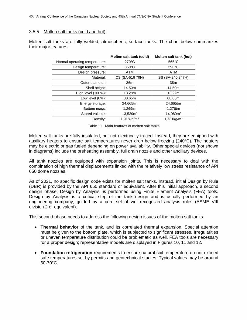
3.5.5 Molten salt tanks (cold and hot)
Molten salt tanks are fully welded, atmospheric, surface tanks. The chart below summarizes their major features.
Molten salt tank (cold) Molten salt tank (hot)
Normal operating temperature: 270°C 565°C
Design temperature: 360°C 590°C
Design pressure: ATM ATM
Material: CS (SA-516 70N) SS (SA-240 347H)
Outer diameter: 36m 38m
Shell height: 14.50m 14.50m
High level (100%): 13.28m 13.22m
Low level (0%): 00.65m 00.65m
Energy storage: 24,665tm 24,665tm
Bottom mass: 1,269tm 1,276tm
Stored volume: 13,520m³ 14,989m³
Density: 1,918kg/m³ 1,731kg/m³
Table 11 Main features of molten salt tanks
Molten salt tanks are fully insulated, but not electrically traced. Instead, they are equipped with auxiliary heaters to ensure salt temperatures never drop below freezing (240°C). The heaters may be electric or gas fueled depending on power availability. Other special devices (not shown in diagrams) include the preheating assembly, full drain nozzle and other ancillary devices.
All tank nozzles are equipped with expansion joints. This is necessary to deal with the combination of high thermal displacements linked with the relatively low stress resistance of API 650 dome nozzles.
As of 2021, no specific design code exists for molten salt tanks. Instead, initial Design by Rule (DBR) is provided by the API 650 standard or equivalent. After this initial approach, a second design phase, Design by Analysis, is performed using Finite Element Analysis (FEA) tools. Design by Analysis is a critical step of the tank design and is usually performed by an engineering company, guided by a core set of well-recognized analysis rules (ASME VIII division 2 or equivalent).
This second phase needs to address the following design issues of the molten salt tanks:
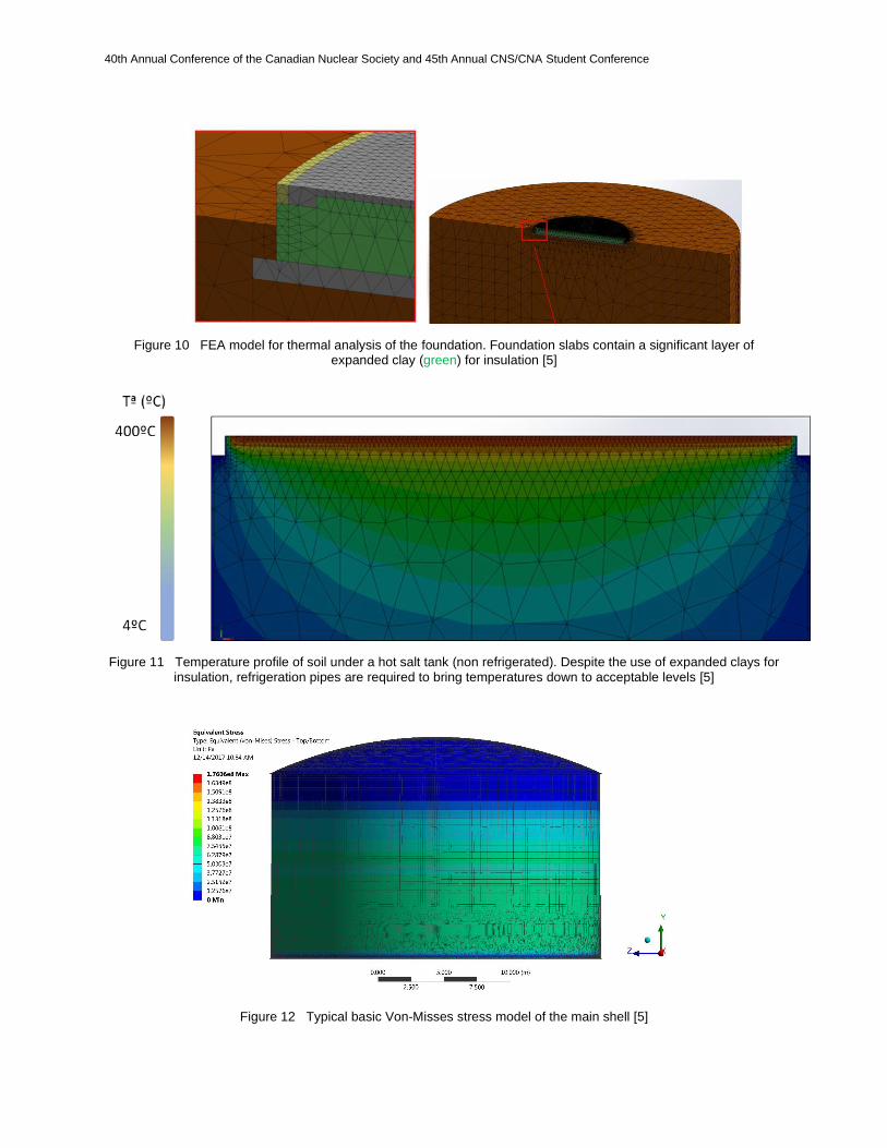
• Thermal behavior of the tank, and its correlated thermal expansion. Special attention must be given to the bottom plate, which is subjected to significant stresses. Irregularities or uneven temperature distribution could be problematic as well. FEA tools are necessary for a proper design; representative models are displayed in Figures 10, 11 and 12.
• Foundation refrigeration requirements to ensure natural soil temperature do not exceed safe temperatures set by permits and geotechnical studies. Typical values may be around 60-70°C.
40th Annual Conference of the Canadian Nuclear Society and 45th Annual CNS/CNA Student Conference
Figure 10 FEA model for thermal analysis of the foundation. Foundation slabs contain a significant layer of expanded clay (green) for insulation [5]
Figure 11 Temperature profile of soil under a hot salt tank (non refrigerated). Despite the use of expanded clays for insulation, refrigeration pipes are required to bring temperatures down to acceptable levels [5]
Figure 12 Typical basic Von-Misses stress model of the main shell [5]

40th Annual Conference of the Canadian Nuclear Society and 45th Annual CNS/CNA Student Conference
Operational experience from thermal storage facilities has revealed issues in the bottom plates of the tanks, particularly in the hot tank. Cracks and creases are a recurrent problem. While multiple factors are at play, it is generally acknowledged that the main reason for failure has to do with the incapacity of the bottom plate to thermally expand, mainly due to excessive friction with the foundation base.
3.5.6 Salt drain recollection tank
The purpose of the drain recollection tank is to collect and redirect the drainage of the salt side of the steam generation train. Drainage is usually redirected to the cold tank but may also be redirected to the hot tank. Drain tanks are also used in the initial fill of the molten salt tanks and during drainage of the tank bottoms.
Drain tank assembly requires a high temperature class stainless steel and is serviced by 2x100% single speed pumps.
3.5.7 Steam generation train
Steam generation trains have process configurations very similar to other power plants, featuring the typical arrangement of economizer, boiler, superheater and various reheaters. Among other design features, molten salt systems include the following:
• Stainless steel construction. All exchangers are manufactured in heat resistant stainless steel (347H or equivalent) since molten salt is corrosive and oxidizing. The only exception is the economizer, which can usually be manufactured in carbon steel as it operates in the cold salt temperature range (<360°C)
• Fully welded design (i.e. zero leaks)
• Water/steam cycle is on the tube side. All heat exchangers have their water cycle on the tube side to facilitate access and maintenance of the tubesheets. This is the reason for the characteristic “pin & head” shape of many salt exchangers.
• Self-draining. Like molten salt pipework, all molten salt exchangers are designed to be self-draining. They usually feature sloped bodies to avoid salt ponding after draining.
A typical water/steam-molten salt heat exchanger is shown in Figure 13.
Figure 13 Typical “pin & head” configuration of a molten salt exchanger [6]
40th Annual Conference of the Canadian Nuclear Society and 45th Annual CNS/CNA Student Conference
Because of the constant nuclear heat flow provided by the SSR-W, there should not be any fatigue damage in the primary and secondary loops as they are not subjected to daily startup and shutdowns, nor daily drainages.
The steam generation trains may still be subjected to fatigue, as peaker configurations require daily startup and shutdown of at least one steam generation train. However, as hot salt is permanently available at a stable temperature, heating ramp control performed by mixing cold and hot salt should be extremely controllable, minimizing any risk of heating runout or thermal shock. Even a minimum flow can be maintained to keep the mechanical equipment warm.
Overall, the salt system is expected to operate very reliability, on a par with standard baseload power generation (typically 98%).
By contrast, a universally present design challenge in molten salt storage systems used by CSP plants is fatigue damage, especially in molten salt heat exchangers belonging to the steam generation train. Because of the daily startup and shutdown routine, a typical CSP plant would be designed for ~400 cycles per year, and subjected to stringent requirements of heating speed, typically no more than 8°C/minute (25°F/minute). This means that the average 30 year plant will be subjected to 12,000 pressure and temperature cycles.
Even more damaging (and more difficult to predict) is fatigue damage caused by thermal shocking. Thermal shocking is not only harder to predict during the design phase, but also difficult to control if ramp heating control is not robust enough.
3.5.8 Pipework
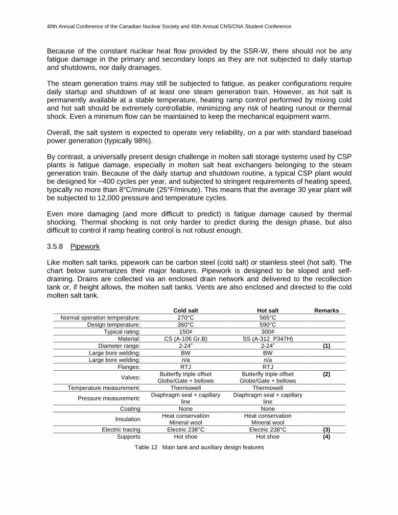
Like molten salt tanks, pipework can be carbon steel (cold salt) or stainless steel (hot salt). The chart below summarizes their major features. Pipework is designed to be sloped and self-draining. Drains are collected via an enclosed drain network and delivered to the recollection tank or, if height allows, the molten salt tanks. Vents are also enclosed and directed to the cold molten salt tank.
Cold salt Hot salt Remarks
Normal operation temperature: 270°C 565°C
Design temperature: 360°C 590°C
Typical rating: 150# 300#
Material: CS (A-106 Gr.B) SS (A-312 P347H)
Diameter range: 2-24” 2-24” (1)
Large bore welding: BW BW
Large bore welding: n/a n/a
Flanges: RTJ RTJ
Valves: Butterfly triple offset
Globe/Gate + bellows Butterfly triple offset
Globe/Gate + bellows (2)
Temperature measurement: Thermowell Thermowell
Pressure measurement: Diaphragm seal + capillary
line Diaphragm seal + capillary
line
Coating None None
Insulation Heat conservation
Mineral wool Heat conservation
Mineral wool
Electric tracing Electric 238°C Electric 238°C (3)
Supports Hot shoe Hot shoe (4)
Table 12 Main tank and auxiliary design features
40th Annual Conference of the Canadian Nuclear Society and 45th Annual CNS/CNA Student Conference
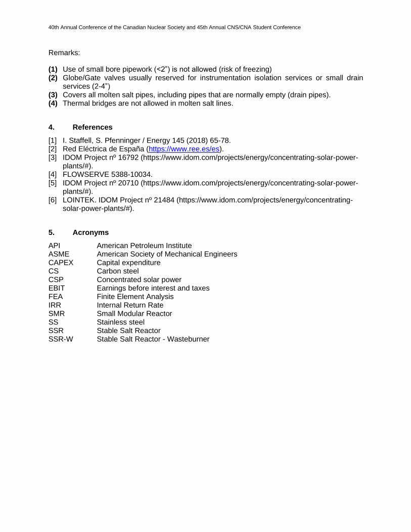
Remarks:
(1) Use of small bore pipework (<2”) is not allowed (risk of freezing) (2) Globe/Gate valves usually reserved for instrumentation isolation services or small drain
services (2-4”) (3) Covers all molten salt pipes, including pipes that are normally empty (drain pipes). (4) Thermal bridges are not allowed in molten salt lines.
4. References
[1] I. Staffell, S. Pfenninger / Energy 145 (2018) 65-78. [2] Red Eléctrica de España (https://www.ree.es/es). [3] IDOM Project nº 16792 (https://www.idom.com/projects/energy/concentrating-solar-power-
plants/#). [4] FLOWSERVE 5388-10034. [5] IDOM Project nº 20710 (https://www.idom.com/projects/energy/concentrating-solar-power-
plants/#). [6] LOINTEK. IDOM Project nº 21484 (https://www.idom.com/projects/energy/concentrating-
solar-power-plants/#).
5. Acronyms
API American Petroleum Institute ASME American Society of Mechanical Engineers CAPEX Capital expenditure CS Carbon steel CSP Concentrated solar power EBIT Earnings before interest and taxes FEA Finite Element Analysis IRR Internal Return Rate SMR Small Modular Reactor SS Stainless steel SSR Stable Salt Reactor SSR-W Stable Salt Reactor - Wasteburner


![Technical Feasibility [Version 1.0]FINAL](https://img.dokumen.tips/doc/110x75/61fb83b92e268c58cd5f1319/technical-feasibility-version-10final.jpg)
