Embed Size (px)
Citation preview
2CD
C 2
51 0
05 V
0013
Data sheet
Grid feeding monitoring according to CEI 0-21CM-UFD.M22
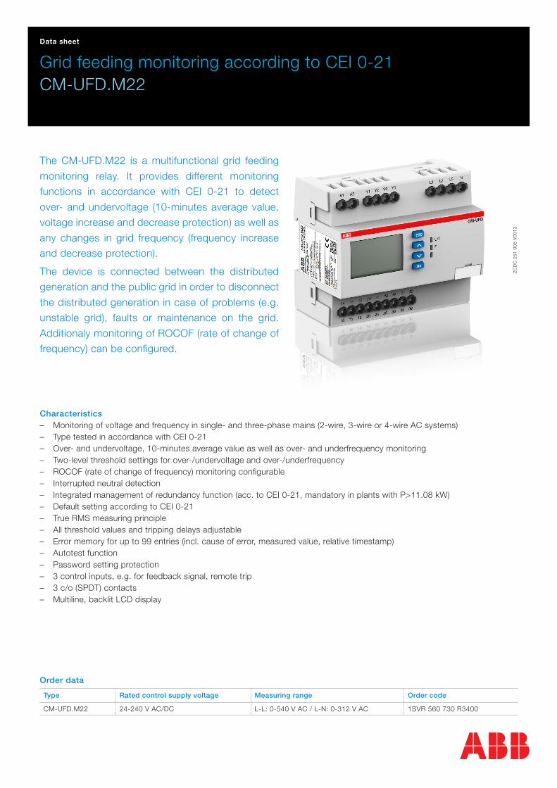
The CM-UFD.M22 is a multifunctional grid feeding
monitoring relay. It provides different monitoring
functions in accordance with CEI 0-21 to detect
over- and undervoltage (10-minutes average value,
voltage increase and decrease protection) as well as
any changes in grid frequency (frequency increase
and decrease protection).
The device is connected between the distributed
generation and the public grid in order to disconnect
the distributed generation in case of problems (e.g.
unstable grid), faults or maintenance on the grid.
Additionaly monitoring of ROCOF (rate of change of
frequency) can be configured.
Characteristics – Monitoring of voltage and frequency in single- and three-phase mains (2-wire, 3-wire or 4-wire AC systems) – Type tested in accordance with CEI 0-21 – Over- and undervoltage, 10-minutes average value as well as over- and underfrequency monitoring – Two-level threshold settings for over-/undervoltage and over-/underfrequency – ROCOF (rate of change of frequency) monitoring configurable – Interrupted neutral detection – Integrated management of redundancy function (acc. to CEI 0-21, mandatory in plants with P>11.08 kW) – Default setting according to CEI 0-21 – True RMS measuring principle – All threshold values and tripping delays adjustable – Error memory for up to 99 entries (incl. cause of error, measured value, relative timestamp) – Autotest function – Password setting protection – 3 control inputs, e.g. for feedback signal, remote trip – 3 c/o (SPDT) contacts – Multiline, backlit LCD display
Order data
Type Rated control supply voltage Measuring range Order code
CM-UFD.M22 24-240 V AC/DC L-L: 0-540 V AC / L-N: 0-312 V AC 1SVR 560 730 R3400

2 - Grid feeding monitoring according to CEI 0-21 | Data sheet
Functions
Operating controls
2CD
C 2
53 0
20 F
0013
1 Display
R1 R2 R3 - relay status; in this case R3 is de-energized
FB - status feedback loop Y1-Y0; in this case FB is closed
EXT – status input external signal; in this case input is closed
REM – status remote trip input; in this case input is closed
2 Indication of operational statesU/T: green LED – V Control supply voltage applied W Timing
F: red LED - Fault message
3 KeypadESC: escape / return to previous menu
^: up / value increase
∨: down / value decrease
OK: enter / confirm selection
Application
The CM-UFD.M22 is a grid feeding monitoring relay (SPI), which is connected between the public grid and the distributed generation (GD) such as photovoltaic systems, wind turbines, block-type thermal power stations. It monitors the voltage and the frequency in the grid and will disconnect the distributed generation (GD) whenever the measured values are not within the range of the adjusted thresholds. The fault is indicated by LED and the corresponding plain text message is shown on the display.
In conformity with CEI 0-21, the CM-UFD.M22 relay can be used in all low voltage plants and in medium voltage plants with power less than 30 kW. The SPI relay is mandatory in all low voltage generation plants with power > 11.08 kW or with more than 3 generators (e.g. plants with more than 3 inverters).
Operating mode
The CM-UFD.M22 can be set up to monitor single- and three-phase mains (2-wire, 3-wire as well as 4-wire AC systems). The unit is configurable by front-face push-buttons. A display with the corresponding menu enables the selection of pre-settings as well as the precise adjustment of the different threshold values and corresponding time delays. Furthermore, the display visualizes the measured values clearly. Together with the front-face LEDs, it shows all information about operational states of output relays and control inputs.
The CM-UFD.M22 provides 3 output relays and 3 control inputs. The first output relay R1 (1115-1216/1418) is required for disconnection of a distributed generation from the public grid (DDI). The corresponding feedback signal from the external contact is monitored via the first control input Y1-Y0 by the internal logic. The second output relay R2 (2125-2226/2428) is redundant to the first one and only activated if output relay R1 has de-energized, but no changed state of the feedback from the external contact (DDI) has been recognized within the adjusted time delay. In case a feedback signal is present, the redundancy relay does not trip. Once the feedback loop did not change its status after the first output changed the status and the DDI should disconnect, the CM-UFD.M22 detects this as a failure (e.g. welded contacts of the DDI contactor) and trips the second output (rincalzo function).
The third output relay R3 (3135-3236/3438) can be used for the closing command of a motor drive for circuit breaker. In case output relay R1 energizes, the adjusted ON-delay starts. When the ON-delay is complete, output relay R3 will be activated for the duration of the ON-time or until R1 de-energizes. In this last case the ON-time is inactive. It is also adjustable to sychronize tripping relay R3 with relay R1.
The operating principle of the relays R2 and R3 is configurable as normally energized (closed-circuit principle) or normally de-energized (open-circuit principle). For safety reasons, the operating principle of R1 is fixed as normally energized (closed-circuit principle) .
Two additional control inputs allow to switch from remote between two sets of frequency threshold settings via Y2-Y0 or to trip the grid feeding monitoring relay via the control input Y3-Y0 (remote trip).
3
2
1

Data sheet | Grid feeding monitoring according to CEI 0-21 - 3
Protective functions
If control supply voltage is applied and all phases are present with voltage and frequency values within their permissible range, output relay R1 (DDI) energizes after the adjusted start-up delay and output relay R2 (DG) energizes or de-energizes, depending on the configuration, after a fixed delay of 1 s. Using the default factory setting, both output relays R1 (DDI) and R2 (DG) will be activated synchronously. The green LED U/T flashes while timing and turns steady when the start-up delay is complete.
If a measured value exceeds or falls below the set threshold value, output relay R1 (DDI) de-energizes after the adjusted delay. The fault is indicated by the red LED F and the type of fault is shown on the display as a plain text message. The event that has caused tripping of the relay is recorded in the event list. The green LED U/T flashes while timing and turns steady when the delay is complete.
As soon as the measured value returns to the tolerance range, taking into account a fixed hysteresis, the red LED F turns off and output relay R1 (DDI) re-energizes after the adjusted re-start delay. The green LED U/T flashes while timing and turns steady when the delay is complete.
Protective function 59 S1 (10-minutes average value): The CM-UFD.M22 calculates the sliding average value of the 3 phases over a period of 10 minutes. The voltage values are updated every 3 seconds. If the 10-minutes average value exceeds the threshold value, the output relays trip.
Redundancy functions
The redundancy relay R2 (DG) is activated if relay R1 (DDI) has de-energized and if no feedback from the external contact has been recognized by the internal logic via the first control input Y1-Y0 within the adjustable time delay. In case a feedback signal is present, the redundancy relay does not trip.
Output relay R3 (3135-3236/3438)
Output relay R3 can be used for the closing command of a breaker motor. In case output relay R1 (DDI) energizes, the adjusted ON-delay starts. When timing is complete, output relay R3 will be activated for the duration of the ON-time or until relay R1 de-energizes. In this last case the ON-time is inactive. The operating principle of relay R3 is configurable as closed-circuit, open-circuit principle, disabled or synchronous with relay 1.
ROCOF (Rate of change of frequency df/dt)
This function monitors the rate of change of frequency within a very short time and detects an imminent loss of mains (islanding).
The ROCOF function will detect zero crossings of the grid voltage. It measures the time between the zero crossings and calculates a new frequency after each zero crossing. In case the frequency changes too much since the last zero crossing, the relay will trip. After the adjusted error time the relay de-energizes automatically.
The ROCOF monitoring function is deactivated per default. It can be activated in the menu.
Interrupted neutral detection
Interrupted neutral detection is always active when phase-neutral measuring principle is selected in the menu “Nominal voltage”. The interruption of the neutral conductor will result in an immediate tripping of output relay R1 (DDI).
Error memory
The CM-UFD.M22 records and logs the last 99 events that caused tripping of the grid feeding monitoring relay as well as any interruption of the control supply voltage. The type of error as well as the current value of the operation counter is recorded into the internal error list, accessible via the menu “Error memory”. The list is stored internally in a non-volatile memory which can be reset by the user.
Local command and external signal
The CEI 0-21 standard defines “restrictive thresholds”, the under- and overfrequency thresholds S1 (49.5-50.5 Hz), and “permissive thresholds”, the under- and overfrequency thresholds S2 (47.5-51.5 Hz). Selection of S1 or S2 thresholds is made by the corresponding combination of the external signal Y2-Y0 and the local command (see tables on page 4).

4 - Grid feeding monitoring according to CEI 0-21 | Data sheet
Working principle Input state Control input
normally open open 0
normally open closed 1
normally closed open 1
normally closed closed 0
Table: Truth table for control inputs External Signal Y2-Y0 and Remote trip Y3-Y0
External signal Local command Active thresholds
0 disabled only S2
1 disabled only S2
0 enabled only S2
1 enabled S1 and S2
Table: Truth table for frequency thresholds
Remote trip
Control input Y3-Y0 allows tripping of the grid feeding monitoring relay from remote. The remote trip input can be configured as normally open or normally closed. If normally closed is configured, the relay trips if Y3-Y0 is opened. If normally open is configured, the relay trips if Y3-Y0 is closed. The output relay 1115-1216/1418 is tripped by the remote trip within less than 20 ms. When the remote trip input is deactivated, the output relay 1115-1216/1418 (DDI) energizes again.
Autotest
The autotest function allows the verification of the protective functions by increasing the lowest threshold and decreasing the highest threshold respectively, until the measured value for input voltage or frequency equals the threshold. Confirming the start of the autotest routine initiates the threshold sweep with the objective of tripping the relay. For each threshold the device displays the measured switching time up from tripping the output relay till the feedback signal from the external contact of the switching device. If the autotest fails, the cause of error has to be analysed and the test needs to be repeated. Output relay 1115-1216/1418 remains de-energized as long as the test has not been passed successfully.
Note: The autotest will cause the CM-UFD.M22 to trip four times within a short time. This may lead to voltage fluctuations in the public grid. Therefore, we recommend to disconnect the generating plant manually from the grid before executing the auto test procedure.
Operating principle
TeledistaccoRemote trip
Misure Measurement
1,10 VnT=3s
0 T
0,40 Vn
1,15 Vn
0,85 Vn
81.S247,5 Hz
81.S150,5 Hz
81.S149,5 Hz
81.S251,5 Hz
Scatto DDITrip DDI
Segnale esternoExternal signal
AND
OR
Comando localeLocal command
T=0,2s0 T
T=0,2s0 T
T=0,4s0 T
T=0,1s0 T
T=0,1s0 T
T=4,0s(or 0,1s)
0 T
T=1s(or 0,1s)
0 T
2CD
C 2
53 0
22 F
0013

Data sheet | Grid feeding monitoring according to CEI 0-21 - 5
Electrical connection
2C
DC
253
023
F00
13
A1-A2
Y1-Y0
Y2-Y0
Y3-Y0
L1, L2, L3, N
1115-1216/1418
2125-2226/2428
3135-3236/3438
Control supply voltage
Control input 1 for feedback signal
Control input 2 for external signal
Control input 3 for remote trip
Measuring input
1st c/o (SPDT) contact
2nd c/o (SPDT) contact
3rd c/o (SPDT) contact
Configuration
The relay is delivered with default settings in accordance to CEI 0-21 table 8. Thanks to the wide backlit display and to appropriate buttons all parameters can be easily set. The user-friendly menu structure starts with the main page that shows the real time measured values. Use the arrow keys to switch between the real time voltages and the 10-minutes average voltages.
Display menu structure, navigation and possible configurations
Main page
Menu navigation
- With a dark display, press any button to light it up
- Press OK button to enter the menu
- Press arrow buttons to move between functions and parameters
- Press OK button to enter the chosen page
- Press arrow buttons to modify the values of the parameters
- Press OK button to confirm the value and proceed
- Press ESC button to return to the previous menu
- Press arrow buttons more than 1 s to scroll through the menu or
password menu
Changes of parameters can be cancelled by pressing the ESC button.
Password protection
Every CM-UFD.M22 relay is delivered with the same default password [0000] for protection of its settings and local command. The installer is responsible for the verification of the parameter values and the change of the password with a personal one in order to avoid unwanted modifications.
Visualization of the parameters is always possible, modification only after having entered the password. While entering the password, the password protection is temporarily disabled until the menu is exited.
Only the parameters ‘autotest’, ‘language’, ‘display switch-off delay’ and ‘contrast’ are not password protected.

6 - Grid feeding monitoring according to CEI 0-21 | Data sheet
Default setting table
Protective functions Threshold Tripping delay
relative absolute
1st overvoltage av. (59 S1) 1.10 Vn 253 V
2nd overvoltage (59 S2) 1.15 Vn 265 V 0.2 s
1st undervoltage (27 S1) 0.85 Vn 196 V 0.4 s
2nd undervoltage (27 S2) 0.40 Vn 92 V 0.2 s
1st overfrequency (81> S1) 50.5 Hz 0.1 s
1st underfrequency (81< S1) 49.5 Hz 0.1 s
2nd overfrequency (81> S2) 51.5 Hz 0.1 s
2nd underfrequency (81< S2) 47.5 Hz 0.1 s
Note: The voltage values in this table refer to phase-neutral (Vn 230 V).
Indication of operational states
LED Status information
U/T: green LED ON Control supply voltage applied
U/T: green LED flashing Timing
F: red LED ON Failure

Data sheet | Grid feeding monitoring according to CEI 0-21 - 7
Menu structure
Main menu displays Submenus displays
OK R
r ESC
OK R
r ESC
∨ down up ∧ ∨ down up ∧
Main menu displays
Submenus displays
Options Configuration possibilities Step size
Nominal voltage Meas. principle [3L-N], [3L-L], [1L-N]
Nominal voltage [100.0] - [230.9] V L-N / [173.2] - [400.0] V L-L 0.1 V
I/O setup Relay 1 settings Start-up delay [1.00] - [600.00] s 0.05 s
Restart delay [0.05] - [600.00] s 0.05 s
Relay 2 settings Working principle [closed-circuit], [open-circuit]
Relay 3 settings Working principle [closed-circuit], [open-circuit], [disabled], [sync. with relay 1]
ON-delay [0.00] - [10.00] s 0.05 s
ON-time [0.05] - [10.00] s 0.05 s
Feedback loop Y1 Working principle [normally closed], [normally open], [auto detection]
Trip window [0.05] - [0.50] s 0.05 s
Release window [0.50] - [600.00] s 0.05 s
External signal Y2 Working principle [normally closed], [normally open]
Remote trip Y3 Working principle [normally closed], [normally open]
Monitoring func. Overvoltage >S1 Threshold value [1.00] - [1.20] * Un 0.01 * Un
Overvoltage >S2 Threshold value [1.00] - [1.30] * Un 0.01 * Un
Tripping delay [0.05] - [600.00] s 0.05 s
Undervoltage <S1 Threshold value [0.20] - [1.00] * Un 0.01 * Un
Tripping delay [0.05] - [600.00] s 0.05 s
Undervoltage <S2 Threshold value [0.05] - [1.00] * Un 0.01 * Un
Tripping delay [0.05] - [600.00] s 0.05 s
Overfrequency >S1 Threshold value [50.0] - [54.0] Hz 0.1 Hz
Tripping delay [0.05] - [600.00] s 0.05 s
Overfrequency >S2 Threshold value [50.0] - [54.0] Hz 0.1 Hz
Tripping delay [0.05] - [600.00] s 0.05 s
Underfrequency <S1 Threshold value [46.0] - [50.0] Hz 0.1 Hz
Tripping delay [0.05] - [600.00] s 0.05 s
Underfrequency <S2 Threshold value [46.0] - [50.0] Hz 0.1 Hz
Tripping delay [0.05] - [600.00] s 0.05 s
ROCOF ROCOF [disabled], [enabled]
Threshold value [0.1] - [1.0] Hz/s 0.1 Hz/s
Error-time [0.05] - [600.00] s 0.05 s
Autotest
General settings Local command Local command [disabled], [enabled]
Change LC password [****]
Language Language [English], [Italiano]
Display Switch-off delay [10] - [600] s 1 s
Contrast [0] - [9]
Password Protection [disabled], [enabled]
Change password [****]
Load settings "Setting name"
Save settings "Setting name"
Information
Error memory Error list
Error recording Remote trip [disabled], [enabled]
Power OFF [disabled], [enabled]
Reset error memory
Operating counter
Cumulated OFF-time

8 - Grid feeding monitoring according to CEI 0-21 | Data sheet
Display and failure messages
When entering, the password is required, in this case E4W3
Error, ROCOF
Error overvoltage S1 in all three phases detected.
If overvoltage occurs in one phase only, >S1 indicates the phase with overvoltage.
4-wire connection The neutral conductor is disconnected or interrupted.
Please check wiring.
Error overvoltage S2 in all three phases detected.
If overvoltage occurs in one phase only, >S2 indicates the phase with overvoltage.
Failure in the feedback loop FB. E.g. wiring failure, configuration failure, welded feedback contact in DDI.
Please check configuration and installation for failures. After failure removal, press ESC to restart/reset.
Error undervoltage S1 in all three phases detected.
If undervoltage occurs in one phase only, <S1 indicates the phase with undervoltage.
Permanent failure in the feedback loop FB. E.g. wiring failure, configuration failure, welded feedback contact in DDI.
Failure in configuration or installation must be removed before the failure can be receipted with ESC.
Error undervoltage S2 in all three phases detected.
If undervoltage occurs in one phase only, <S2 indicates the phase with undervoltage.
Failure within the logic or hardware of the device. Remove supply and restart. If failure still occurs, there is a permanent failure in the device.
Error overfrequency S1 detected Feedback of DDI interrupted or failure.
Error overfrequency S2 detected Main display / start display after autotest failure.
Restart autotest
Error underfrequency S1 detected Remote trip shows that the remote trip is activated and output relay R1 is de-energized.
Error underfrequency S2 detected

Data sheet | Grid feeding monitoring according to CEI 0-21 - 9
Error memory
As soon as one of the above errors occurs, subsequent error codes with the corresponding time stamp will be stored in the error memory:
Storage position in the error list
Error code
Time stamp In this case the error occured 8 hours, 3 minutes and 15 seconds after commissioning
Error code Explanation
L1N>S1 or L2N>S1 or L3N>S1 Error, overvoltage S1 10-minutes average value
L1N>S2 or L2N>S2 or L3N>S2 Error, overvoltage S2
L1N<S1 or L2N<S1 or L3N<S1 Error, undervoltage S1
L1N<S2 or L2N<S2 or L3N<S2 Error, undervoltage S2
L12>S1 or L23>S1 or L31>S1 Error, overvoltage S1 10-minutes average value
L12>S2 or L23>S2 or L31>S2 Error, overvoltage S2
L12<S1 or L23<S1 or L31<S1 Error, undervoltage S1
L12<S2 or L23<S2 or L31<S2 Error, undervoltage S2
F>S1 Error, overfrequency S1
F>S2 Error, overfrequency S2
F<S1 Error, underfrequency S1
F<S2 Error, underfrequency S2
ROCOF Error, ROCOF
AUTO Error, autotest Failure during the autotest routine
REMOTE Error, remote trip
DDI-FB Error, DDI feedback Malfunction of the DDI
POWER Error, power Supply voltage is disconnected or too low
NEUTRAL Error, interrupted neutral detection
Exxx (e.g. E123) Internal error Failure within the logic or hardware of the device
10 - Grid feeding monitoring according to CEI 0-21 | Data sheet
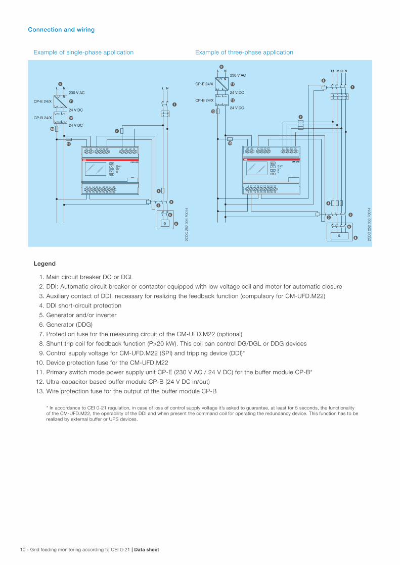
Connection and wiring
Example of single-phase application Example of three-phase application
2CD
C 2
52 0
04 F
0014
2CD
C 2
52 0
03 F
0014
Legend
1. Main circuit breaker DG or DGL
2. DDI: Automatic circuit breaker or contactor equipped with low voltage coil and motor for automatic closure
3. Auxiliary contact of DDI, necessary for realizing the feedback function (compulsory for CM-UFD.M22)
4. DDI short-circuit protection
5. Generator and/or inverter
6. Generator (DDG)
7. Protection fuse for the measuring circuit of the CM-UFD.M22 (optional)
8. Shunt trip coil for feedback function (P>20 kW). This coil can control DG/DGL or DDG devices
9. Control supply voltage for CM-UFD.M22 (SPI) and tripping device (DDI)*
10. Device protection fuse for the CM-UFD.M22
11. Primary switch mode power supply unit CP-E (230 V AC / 24 V DC) for the buffer module CP-B*
12. Ultra-capacitor based buffer module CP-B (24 V DC in/out)
13. Wire protection fuse for the output of the buffer module CP-B
* In accordance to CEI 0-21 regulation, in case of loss of control supply voltage it’s asked to guarantee, at least for 5 seconds, the functionality of the CM-UFD.M22, the operability of the DDI and when present the command coil for operating the redundancy device. This function has to be realized by external buffer or UPS devices.
A1
14 11 12 24 21 22 34 31 32
18 15 16 28 25 26 38 35 36
A2 Y1 L1 L2 L3 NY2 Y3 Y0
ESC
OK
CM-UFD
U/TF
230 V AC
24 V DC
24 V DC
L N L N
L1 N
L+
L+IN L-IN
L+OUTL-OUT
L-
CP-E 24/X
CP-B 24/X
G
13
12
11
9
7
10
1
4
23
6
5
A1
14 11 12 24 21 22 34 31 32
18 15 16 28 25 26 38 35 36
A2 Y1 L1 L2 L3 NY2 Y3 Y0
ESC
OK
CM-UFD
U/TF
230 V AC
24 V DC
24 V DC
L N
L1 N
L+
L+IN L-IN
L+OUTL-OUT
L-
CP-E 24/X
CP-B 24/X
L1 L2 L3 N
G
1
8
7
9
11
12
13
10
4
23
6
5

Data sheet | Grid feeding monitoring according to CEI 0-21 - 11
Technical data
Data at Ta = 25 °C and rated values, unless otherwise indicated
Input circuits
Supply circuit A1-A2
Rated control supply voltage Us 24-240 V AC/DC
Rated control supply voltage Us tolerance -15...+10 %
Rated frequency DC or 50 Hz
Frequency range AC 40-60 Hz
Typical current / power consumption 24 V DC 64 mA / 1.5 W
230 V AC 6.4 mA / 1.5 VA
External fusing (necessary) 6 A gG (gL) or circuit breaker 6 A with B characteristic
Power failure buffering time 200 ms, according to LVFRT (Low Voltage Fault Ride Through)
Measuring circuits L1, L2, L3, N
Monitoring functions acc. to CEI 0-21 overvoltage av. (59 S1)
overvoltage (59 S2)
undervoltage (27 S1)
undervoltage (27 S2)
overfrequency (81>S1)
underfrequency (81<S1)
overfrequency (81>S2)
underfrequency (81<S2)
ROCOF, configurable
neutral, activated if L-N
Measuring ranges voltage (4-wire system L1, L2, L3-N) 0-312 V AC
voltage (3-wire system L1, L2, L3) 0-540 V AC
voltage (2-wire system L-N) 0-312 V AC
frequency 40-60 Hz
Accuracy of measurements voltage m 2 %
frequency w 20 mHz
delay times m 5 % w 20 ms
Accuracy within the temperature range iU m 0.02 %/°C
Threshold values overvoltage av. (59 S1) adjustable, 1.00-1.30*Un in 0.01*Un steps
overvoltage (59 S2) adjustable, 1.00-1.20*Un in 0.01*Un steps
undervoltage (27 S1) adjustable, 0.20-1.00*Un in 0.01*Un steps
undervoltage (27 S2) adjustable, 0.05-1.00*Un in 0.01*Un steps
overfrequency (81>S1) adjustable, 50.0-54.0 Hz in 0.1 Hz steps
underfrequency (81<S1) adjustable, 46.0-50.0 Hz in 0.1 Hz steps
overfrequency (81>S2) adjustable, 50.0-54.0 Hz in 0.1 Hz steps
underfrequency (81<S2) adjustable, 46.0-50.0 Hz in 0.1 Hz steps
ROCOF adjustable, 0.1-1.0 Hz/s in 0.1 Hz/s steps
Hysteresis related to the threshold values overvoltage 0.95-0.97*Un
undervoltage 1.03-1.05*Un
overfrequency 0.997-0.999*fn
underfrequency 1.001-1.003*fn
Tripping delay acc. to CEI 0-21 overvoltage 2 adjustable, 0.05-600.00 s in 0.05 s steps,
w 3 % w 20 msundervoltage 1
undervoltage 2
overfrequency 1
overfrequency 2
underfrequency 1
underfrequency 2
Tripping delay interrupted neutral conductor < 150 ms
Measuring cycle at 50 Hz ROCOF 640 ms

12 - Grid feeding monitoring according to CEI 0-21 | Data sheet
Control circuits Y0, Y1, Y2, Y3
Number 3
Type of triggering volt-free triggering, signal source Y0
Control function Y1-Y0 control input 1 DDI feedback, trip and release monitoring times adjustable
Y2-Y0 control input 2 external signal
Y3-Y0 control input 3 remote trip
Electrical isolation from the supply voltage yes
from the measuring circuit no
from the relay outputs yes
Maximum switching current in the control circuit 6 mA
No-load voltage at the control inputs (Y1-Y0, Y2-Y0, Y3-Y0) 22-26 V DC
Minimum control pulse length 20 ms
Maximum cable length at the control inputs (unshielded) 10 m
Timing functions
Start-up delay R1 (prior to first grid connection or re-connection after interruption) adjustable, 1.00-600.00 s in 0.05 s steps
Restart delay R1 adjustable, 0.05-600.00 s in 0.05 s steps
Start-up delay R2 (prior to first grid connection or re-connection after interruption) 1 s, fixed
ON-delay R3 adjustable, 0.00-10.00 s in 0.05 s steps
ON-time R3 adjustable, 0.05-10.00 s in 0.05 s steps
Trip window, feedback loop Y1 adjustable, 0.05-0.50 s in 0.05 s steps
Release window, feedback loop Y1 adjustable, 0.50-600.00 s in 0.05 s steps
Tripping delays adjustable, 0.05-600.00 s in 0.05 s steps
ROCOF error time adjustable, 0.05-600.00 s in 0.05 s steps
User interface
Indication of operational states
Control supply voltage applied / timing U/T LED green on / flashing
Fault message F LED red on
For details see the message on the display
Display
Backlight on press any button
off switch-off delay adjustable, 10-600 s (default 10 s)
Operating temperature range of the display clearly visible -20...+60 °C
Resolution 112 x 64 pixel
Display size 36 x 22 mm
Operating controls
4 push-buttons for menu navigation, setting and entering

Data sheet | Grid feeding monitoring according to CEI 0-21 - 13
Output circuits
Kind of outputs 11-12/14 (15-16/18) 1st c/o (SPDT) contact, tripping relay for DDI
21-22/24 (25-26/28) 2nd c/o (SPDT) contact, redundancy relay for DG
31-32/34 (35-36/38) 3rd c/o (SPDT) contact, closing command for breaker motor,
also sync. with relay 1
Operating principle 11-12/14 closed-circuit principle1)
21-22/24 open- or closed-circuit principle1) configurable
31-32/34 open- or closed-circuit principle1) configurable
Contact material AgNi alloy, Cd free
Rated operational voltage Ue 250 V AC
Minimum switching voltage / minimum switching current 24 V / 10 mA
Maximum switching voltage / maximum switching current see ‘Load limit curves’
Rated operating current Ie AC-12 (resistive) at 230 V 4 A
AC-15 (inductive) at 230 V 3 A
DC-12 (resistive) at 24 V 4 A
DC-13 (inductive) at 24 V 2 A
Mechanical lifetime 30 x 106 switching cycles
Electrical lifetime at AC-12, 230 V AC, 4 A 50 x 103 switching cycles
Maximum fuse rating to achieve
short-circuit protection
n/c contact 10 A fast-acting
n/o contact 10 A fast-acting
Maximum closing current (short time) t < 20 ms 30 A
t < 80 ms 17 A
Conventional thermal current Ith 5 A
1) Closed-circuit principle: Output relay de-energizes if a fault is occuring Open-circuit principle: Output relay energizes if a fault is occuring
General data
MTBF on request
Repeat accuracy (constant parameters) < w 0.5 %
Duty time 100 %
Dimensions see ‘Dimensional drawing’
Weight 0.306 kg (0.675 lb)
Material of housing PA666FR
Mounting DIN rail (IEC/EN 60715) TH 35-7.5 and TH 35-15,
snap-on mounting without any tool
Mounting position any
Minimum distance to other units horizontal / vertical not necessary
Degree of protection housing / terminals IP20
Electrical connection
Connecting capacity fine-strand with wire end ferrule 1 x 0.25-4 mm² (1 x 24-12 AWG)
2 x 0.25-0.75 mm² (2 x 24-18 AWG)
fine-strand without wire end ferrule 1 x 0.2-4 mm² (1 x 24-12 AWG)
2 x 0.2-1.5 mm² (2 x 24-16 AWG)
rigid 1 x 0.2-6 mm² (1 x 24-10 AWG)
2 x 0.2-1.5 mm² (2 x 24-16 AWG)
Stripping length 8 mm (0.315 in)
Tightening torque 0.5-0.6 Nm (4.4-5.3 lb.in)

14 - Grid feeding monitoring according to CEI 0-21 | Data sheet
Environmental data
Ambient temperature ranges operation -20 °C...+60 °C (-4...+140 °F)
storage -20 °C...+80 °C (-4...+176 °F)
Damp heat, cyclic IEC/EN 60068-2-30 6 x 24 h cycle, 55 °C, 95 % RH
Climatic class IEC/EN 60721-3-3 3K5 (no condensation, no ice formation)
Vibration, sinusoidal Class 2
Shock Class 2
Isolation data
Rated insulation voltage Ui supply / measuring / output circuits 600 V
output 1 / output 2 / output 3 300 V
Rated impulse withstand voltage Uimp supply / measuring / output circuits 6 kV; 1.2/50 µs
output 1 / output 2 / output 3 4 kV; 1.2/50 µs
Basic insulation supply / measuring / output circuits 600 V AC
output 1 / output 2 / output 3 300 V AC
Protective separation
(IEC/EN 61140)
supply / measuring / output circuits 250 V
output 1 / output 2 / output 3 250 V
Pollution degree 3
Overvoltage category IEC/EN 60664-1 III
Overvoltage category CEI 0-21 IV
Standards / Directives
Standards IEC/EN 60255-27, EN 50178, CEI 0-21
Low Voltage Directive 2014/35/EU
EMC Directive 2014/30/EU
RoHS Directive 2011/65/EU
Electromagnetic compatibility
Interference immunity to IEC/EN 61000-6-2, CEI 0-21 Tab.11
electrostatic discharge IEC/EN 61000-4-2 Level 3, 6 kV contact discharge, 8 kV air discharge
radiated, radio-frequency, electromagnetic field IEC/EN 61000-4-3 Level 3, 10 V/m
electrical fast transient / burst IEC/EN 61000-4-4 Level 3, 2 kV / 5 kHz
surge IEC/EN 61000-4-5 Level 3, installation class 3,
supply circuit and measuring circuit 1 kV L-L, 2 kV L-N
conducted disturbances, induced by radio-
frequency fields
IEC/EN 61000-4-6 Level 3, 10 V
voltage dips, short interruptions and voltage
variations
IEC/EN 61000-4-11 Class 3
harmonics and interharmonics IEC/EN 61000-4-13 Class 3
Interference emission IEC/EN 61000-6-3
high-frequency radiated IEC/CISPR 22, EN 55022 Class B
high-frequency conducted IEC/CISPR 22, EN 55022 Class B

Data sheet | Grid feeding monitoring according to CEI 0-21 - 15
Technical diagrams
Load limits curves
300
200
1008060504030
20
101 2 4 6 10
I A
V
V
0.1 0.2 0.5
2CD
C 2
52 1
94 F
0205
AC load (resistive)
cos ϕ
F
0.5
0.1 0.2 0.3 0.4 0.5 0.6 0.7 0.8 0.9 1.0
0.6
0.7
0.8
0.9
1.0
2CD
C 2
52 1
92 F
0205
Derating factor F at inductive AC load
300
200
1008060504030
20
101 2 4 6 10
I A
V
V
0.1 0.2 0.5
2CD
C 2
52 1
93 F
0205
DC load (resistive)
Switching current [A]
250 Vresistive load
Sw
itchi
ng c
ycle
s
2CD
C 2
52 1
48 F
0206
Contact lifetime

16 - Grid feeding monitoring according to CEI 0-21 | Data sheet
Dimensions
in mm and inches
90
3.54
”
108 4.25”67 2.64”
2CD
C 2
52 0
08 F
0013
Further documentation
Document title Document type Document number
Electronic relays and controls Catalog 2CDC 110 004 C02xx
CM-UFD.M22 Grid feeding monitoring relay Instruction sheet 1SVC 560 510 M0001
You can find the documentation on the internet at www.abb.com/lowvoltage -> Automation, control and protection -> Electronic relays and controls -> Measuring and monitoring relays.
CAD system files
You can find the CAD files for CAD systems at http://abb-control-products.partcommunity.com -> Low Voltage Products & Systems -> Control Products -> Electronic Relays and Controls.

ABB STOTZ-KONTAKT GmbHP. O. Box 10 16 8069006 Heidelberg, GermanyPhone: +49 (0) 6221 7 01-0Fax: +49 (0) 6221 7 01-13 25E-mail: [email protected]
You can find the address of your local sales organisation on the ABB home pagehttp://www.abb.com/contacts -> Low Voltage Products and Systems
Contact us
Note:We reserve the right to make technical changes or modify the contents of this document without prior notice. With regard to purchase orders, the agreed particulars shall prevail. ABB AG does not accept any responsibility whatsoever for potential errors or possible lack of information in this document.
We reserve all rights in this document and in the subject matter and illustrations contained therein. Any reproduction, disclosure to third parties or utilization of its contents – in whole or in parts – is forbidden without prior written consent of ABB AG.
Copyright© 2017 ABB All rights reserved
Do
cum
ent
num
ber
2C
DC
112
001
D02
00 (0
3.20
17)