Embed Size (px)
Citation preview
COPYRIGHT © 2011 ALCATEL-LUCENT. ALL RIGHTS RESERVED. ALCATEL-LUCENT — INTERNAL PROPRIETARY — USE PURSUANT TO COMPANY INSTRUCTION
Greening the telecom industry
TREND PhD Summer School on GREEN NETWORKING
July 2013
Alberto CONTE - Alcatel-Lucent Bell labs
2
COPYRIGHT © 2011 ALCATEL-LUCENT. ALL RIGHTS RESERVED. ALCATEL-LUCENT — INTERNAL PROPRIETARY — USE PURSUANT TO COMPANY INSTRUCTION
Plan
• General intro
• Cellular networks
• Optical backhaul
Always-on Q&A
Don’t wait the last slide to ask about the first…
3
COPYRIGHT © 2011 ALCATEL-LUCENT. ALL RIGHTS RESERVED. ALCATEL-LUCENT — INTERNAL PROPRIETARY — USE PURSUANT TO COMPANY INSTRUCTION
General Introduction
4
COPYRIGHT © 2011 ALCATEL-LUCENT. ALL RIGHTS RESERVED. ALCATEL-LUCENT — INTERNAL PROPRIETARY — USE PURSUANT TO COMPANY INSTRUCTION
General Introduction plan
• Do we need to “green” ICT?
• Where the energy is consumed?
• Real drivers
[References]
5
COPYRIGHT © 2011 ALCATEL-LUCENT. ALL RIGHTS RESERVED. ALCATEL-LUCENT — INTERNAL PROPRIETARY — USE PURSUANT TO COMPANY INSTRUCTION
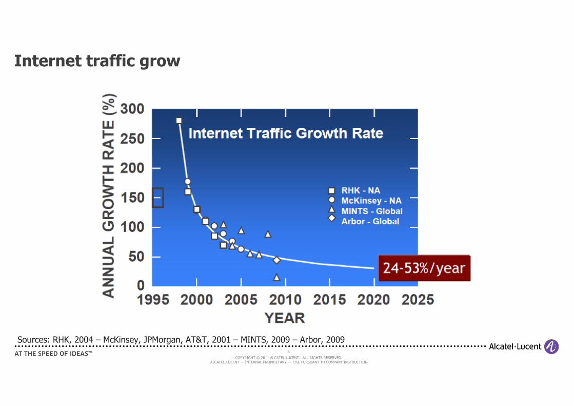
Internet traffic grow
Sources: RHK, 2004 – McKinsey, JPMorgan, AT&T, 2001 – MINTS, 2009 – Arbor, 2009
6
COPYRIGHT © 2011 ALCATEL-LUCENT. ALL RIGHTS RESERVED. ALCATEL-LUCENT — INTERNAL PROPRIETARY — USE PURSUANT TO COMPANY INSTRUCTION
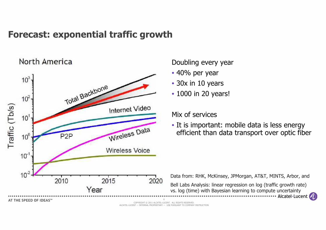
Forecast: exponential traffic growth
Doubling every year
• 40% per year
• 30x in 10 years
• 1000 in 20 years!
Mix of services
• It is important: mobile data is less energy efficient than data transport over optic fiber
Data from: RHK, McKinsey, JPMorgan, AT&T, MINTS, Arbor, and
Bell Labs Analysis: linear regression on log (traffic growth rate) vs. log (time) with Bayesian learning to compute uncertainty
7
COPYRIGHT © 2011 ALCATEL-LUCENT. ALL RIGHTS RESERVED. ALCATEL-LUCENT — INTERNAL PROPRIETARY — USE PURSUANT TO COMPANY INSTRUCTION
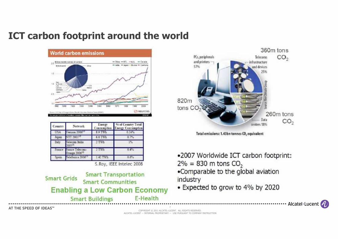
ICT carbon footprint around the world
8
COPYRIGHT © 2011 ALCATEL-LUCENT. ALL RIGHTS RESERVED. ALCATEL-LUCENT — INTERNAL PROPRIETARY — USE PURSUANT TO COMPANY INSTRUCTION
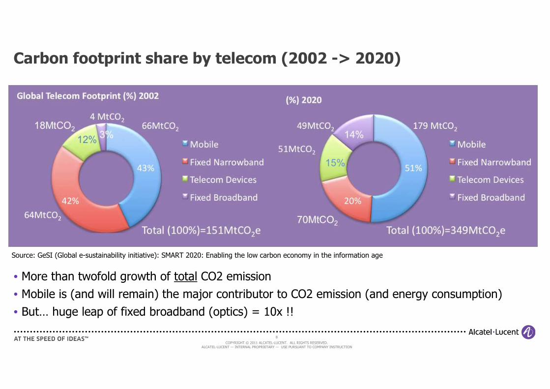
Carbon footprint share by telecom (2002 -> 2020)
• More than twofold growth of total CO2 emission
• Mobile is (and will remain) the major contributor to CO2 emission (and energy consumption)
• But… huge leap of fixed broadband (optics) = 10x !!
Source: GeSI (Global e-sustainability initiative): SMART 2020: Enabling the low carbon economy in the information age
9
COPYRIGHT © 2011 ALCATEL-LUCENT. ALL RIGHTS RESERVED. ALCATEL-LUCENT — INTERNAL PROPRIETARY — USE PURSUANT TO COMPANY INSTRUCTION
Real drivers
Carbon footprint (CO2 emission) is important but…
• … need a political/societal push to force the industry to spend money to reduce it
What is really “enabling” the green revolution is the forecast (and observed tendency) on the explosion of energy consumption of telecom networks…
• … thus the explosion of the energy bill…
• … and the need for operators to reduce its impact on the network TCO (Total Cost of Ownership, includes CAPEX and OPEX)
Telecom ecosystem (industry and research) is reacting:
…

10
COPYRIGHT © 2011 ALCATEL-LUCENT. ALL RIGHTS RESERVED. ALCATEL-LUCENT — INTERNAL PROPRIETARY — USE PURSUANT TO COMPANY INSTRUCTION
References
- GreenTouch Vision, Targets and Research Activities (public: http://www.greentouch.org/uploads/documents/GreenTouch_Celtic_Plus_Elmirghani.pdf)
11
COPYRIGHT © 2011 ALCATEL-LUCENT. ALL RIGHTS RESERVED. ALCATEL-LUCENT — INTERNAL PROPRIETARY — USE PURSUANT TO COMPANY INSTRUCTION
Cellular Networks
12
COPYRIGHT © 2011 ALCATEL-LUCENT. ALL RIGHTS RESERVED. ALCATEL-LUCENT — INTERNAL PROPRIETARY — USE PURSUANT TO COMPANY INSTRUCTION
Cellular Networks plan
• Understanding cellular networks
- Network architecture
- Base Stations
- Backhauling
- Base Station power consumption
• Modeling cellular networks
• Energy inefficiencies in today cellular networks
• Going green : overview of energy-efficiency improvement techniques
[References]
13
COPYRIGHT © 2011 ALCATEL-LUCENT. ALL RIGHTS RESERVED. ALCATEL-LUCENT — INTERNAL PROPRIETARY — USE PURSUANT TO COMPANY INSTRUCTION
Generic cellular network architecture
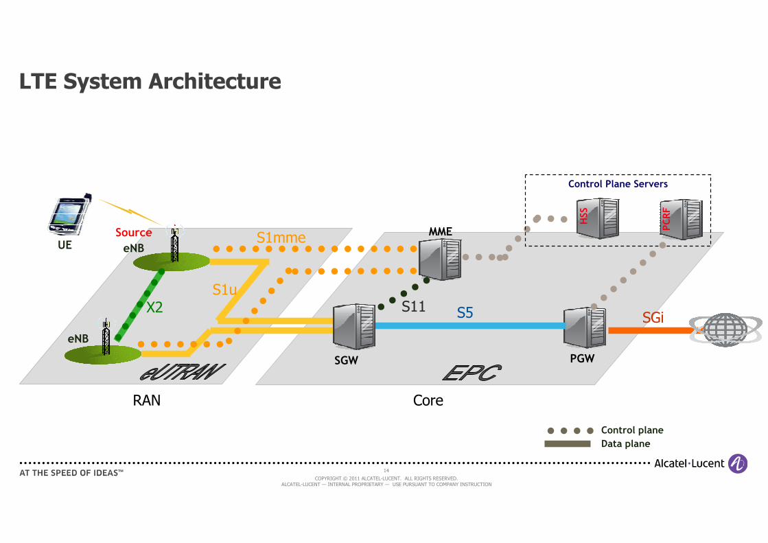
• Composed of two “sections”: Radio Access Network (RAN) and Core Network (CN)
• RAN
- In charge of handling the last-hop (i.e. through the air interface) with the mobile terminal: BS ↔ UE
- Handles everything related to radio aspects, and isolates such details from the core
• Core
- Interfaces with the “external world” (Internet, VPN end-points, etc…)
- Provides IP anchoring (and thus IP address to the UE)
- In charge of traffic control and routing, and AAA (authentication, authorization and accounting)
• In modern architectures IP networking is massively used
- Inside RAN
- Between RAN and Core
- Inside Core
14
COPYRIGHT © 2011 ALCATEL-LUCENT. ALL RIGHTS RESERVED. ALCATEL-LUCENT — INTERNAL PROPRIETARY — USE PURSUANT TO COMPANY INSTRUCTION
LTE System Architecture
HSS
Control Plane Servers
SGW
eNB
Source
eNBUE
Control plane
Data plane
PCRF
MME
PGW
X2S1u
S1mme
S5 SGiS11
RAN Core
15
COPYRIGHT © 2011 ALCATEL-LUCENT. ALL RIGHTS RESERVED. ALCATEL-LUCENT — INTERNAL PROPRIETARY — USE PURSUANT TO COMPANY INSTRUCTION
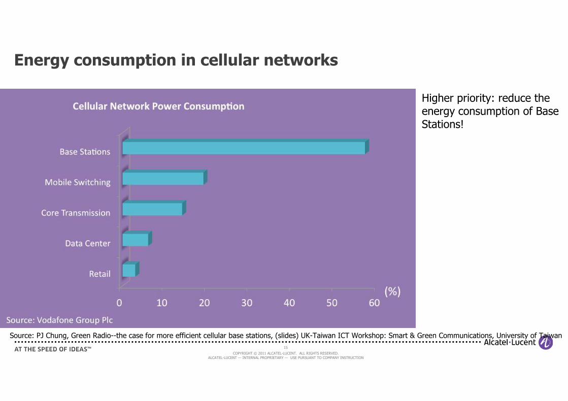
Energy consumption in cellular networks
Source: PJ Chung, Green Radio--the case for more efficient cellular base stations, (slides) UK-Taiwan ICT Workshop: Smart & Green Communications, University of Taiwan
Higher priority: reduce the energy consumption of Base Stations!
16
COPYRIGHT © 2011 ALCATEL-LUCENT. ALL RIGHTS RESERVED. ALCATEL-LUCENT — INTERNAL PROPRIETARY — USE PURSUANT TO COMPANY INSTRUCTION
What is a Base Station? 1/2
• Base Station (BS) is in charge of transmitting/receiving information to/from the mobile terminal (or user Equipment, UE) over the air interface
- Downlink: BS → UE
- Uplink: UE → BS
• Two main telecom components
- Baseband unit (BBU): performs all the digital signal processing transforming the bits into I/Q samples in DL (and vice versa in UL)
- Radio head (RH):
- DL: transforms digital I/Q coming from BBU into analog signal, amplifies it and transmit it through the antenna
- UL: receives the radio signal, amplifies (LNA) and filters it, convert into digital samples (I/Q), send them to BBU
• Additional components: power supply units, AC-DC and DC-DC converters, cooling, I/O interfaces (e.g. Eth)
17
COPYRIGHT © 2011 ALCATEL-LUCENT. ALL RIGHTS RESERVED. ALCATEL-LUCENT — INTERNAL PROPRIETARY — USE PURSUANT TO COMPANY INSTRUCTION
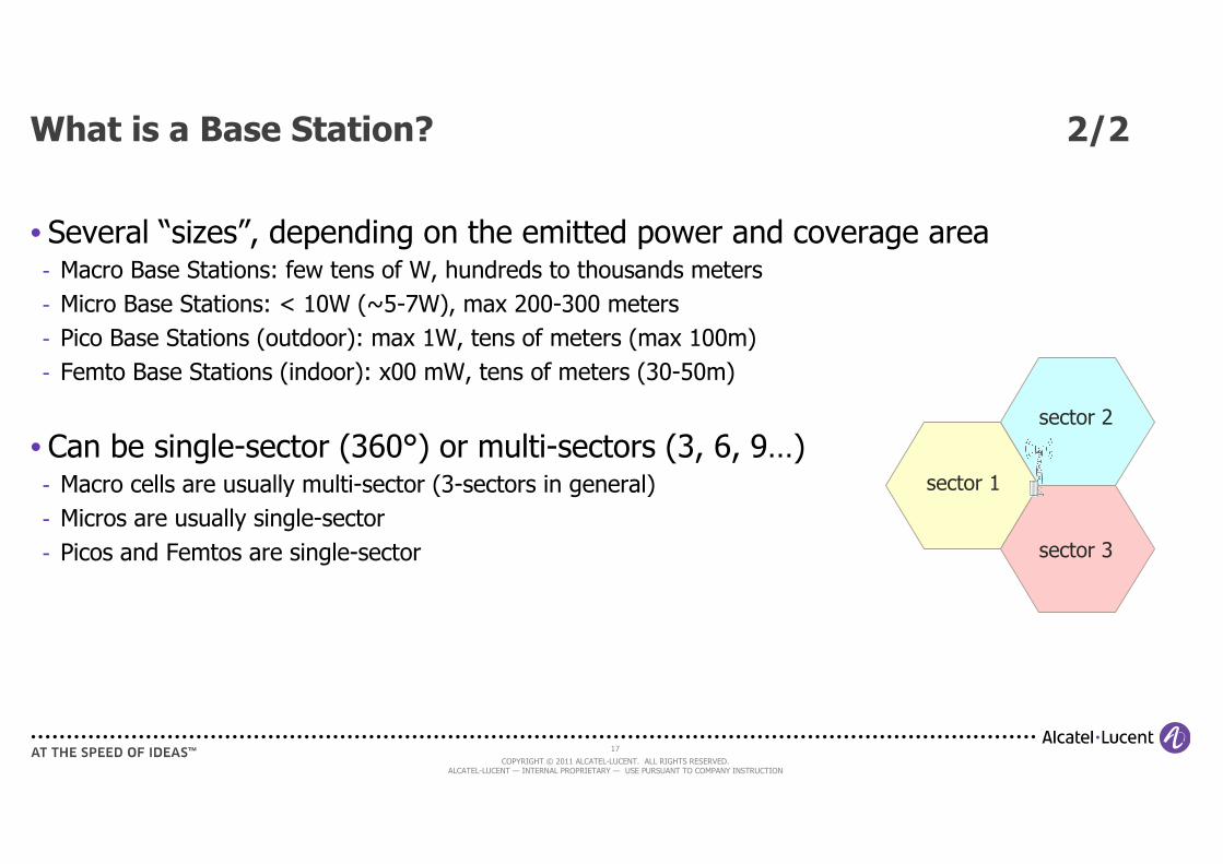
What is a Base Station? 2/2
• Several “sizes”, depending on the emitted power and coverage area- Macro Base Stations: few tens of W, hundreds to thousands meters
- Micro Base Stations: < 10W (~5-7W), max 200-300 meters
- Pico Base Stations (outdoor): max 1W, tens of meters (max 100m)
- Femto Base Stations (indoor): x00 mW, tens of meters (30-50m)
• Can be single-sector (360°) or multi-sectors (3, 6, 9…)- Macro cells are usually multi-sector (3-sectors in general)
- Micros are usually single-sector
- Picos and Femtos are single-sector
sector 1
sector 2
sector 3
18
COPYRIGHT © 2011 ALCATEL-LUCENT. ALL RIGHTS RESERVED. ALCATEL-LUCENT — INTERNAL PROPRIETARY — USE PURSUANT TO COMPANY INSTRUCTION
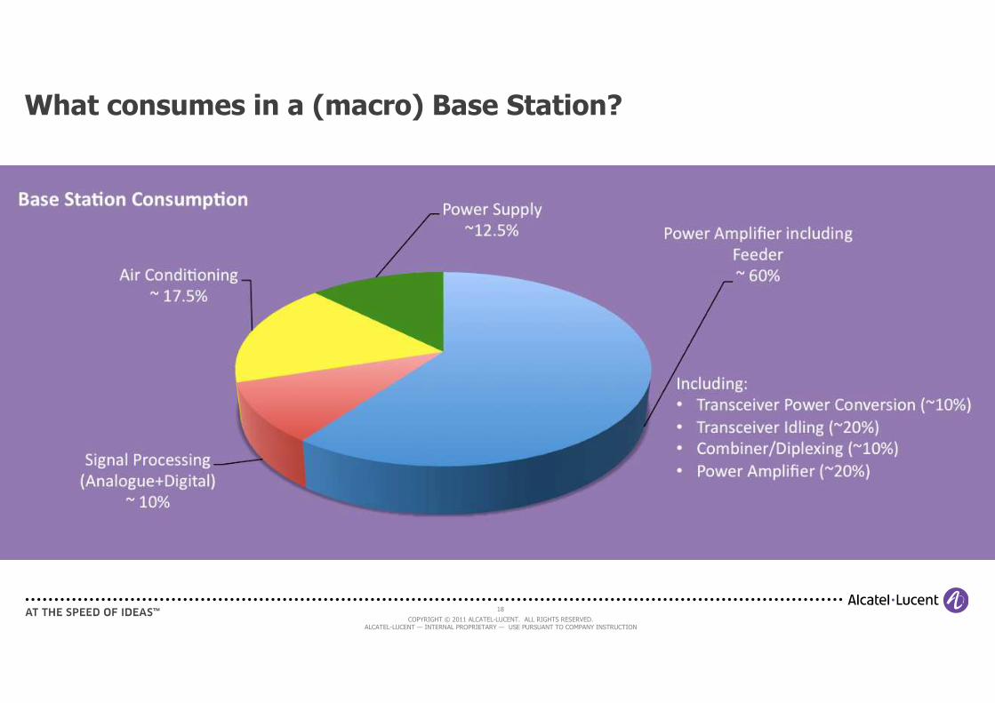
What consumes in a (macro) Base Station?
19
COPYRIGHT © 2011 ALCATEL-LUCENT. ALL RIGHTS RESERVED. ALCATEL-LUCENT — INTERNAL PROPRIETARY — USE PURSUANT TO COMPANY INSTRUCTION
analogue
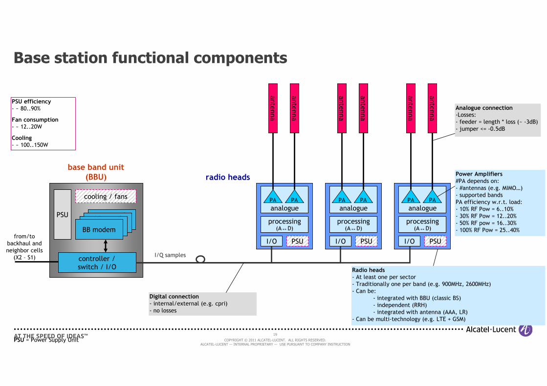
Base station functional components
cooling / fans
antenna
PSU
controller /
switch / I/O
base band unit(BBU)
antenna
antenna
antenna
antenna
antenna
Digital connection- internal/external (e.g. cpri)
- no losses
from/to
backhaul and
neighbor cells
(X2 – S1)
processing(A↔D)
PAPA
I/O PSU
analogue
processing(A↔D)
PAPA
I/O PSU
analogue
processing(A↔D)
PAPA
I/O PSU
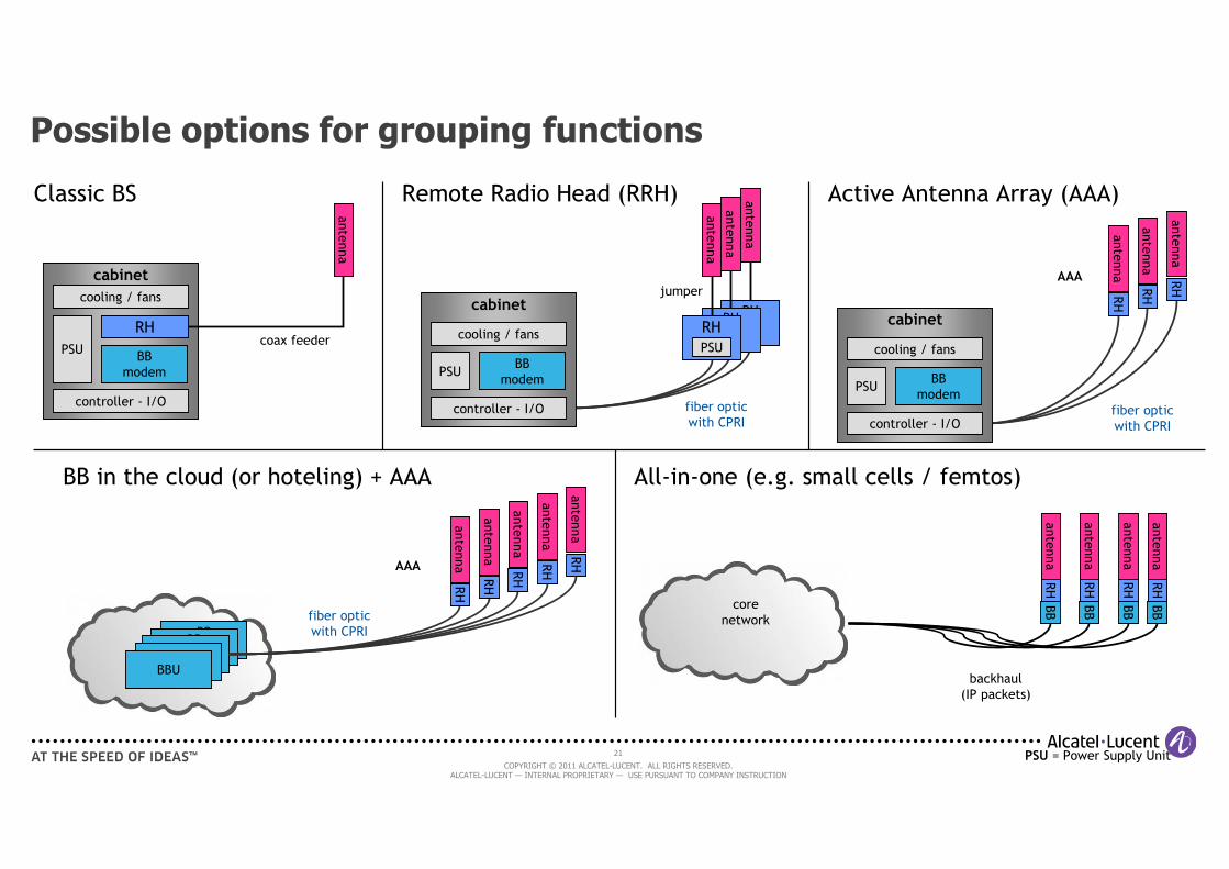
Radio heads- At least one per sector
- Traditionally one per band (e.g. 900MHz, 2600MHz)
- Can be:
- integrated with BBU (classic BS)
- independent (RRH)
- integrated with antenna (AAA, LR)
- Can be multi-technology (e.g. LTE + GSM)
radio heads
Analogue connection-Losses:
- feeder = length * loss (~ -3dB)
- jumper <= -0.5dB
Power Amplifiers#PA depends on:
- #antennas (e.g. MIMO…)
- supported bands
PA efficiency w.r.t. load:
- 10% RF Pow = 6..10%
- 30% RF Pow = 12..20%
- 50% RF pow = 16..30%
- 100% RF Pow = 25..40%
PSU = Power Supply Unit
I/Q samples
PSU efficiency- ~ 80..90%
Fan consumption- ~ 12..20W
Cooling- ~ 100..150W
BB signal
processingBB signal
processingBB signal
processingBB modem
20
COPYRIGHT © 2011 ALCATEL-LUCENT. ALL RIGHTS RESERVED. ALCATEL-LUCENT — INTERNAL PROPRIETARY — USE PURSUANT TO COMPANY INSTRUCTION
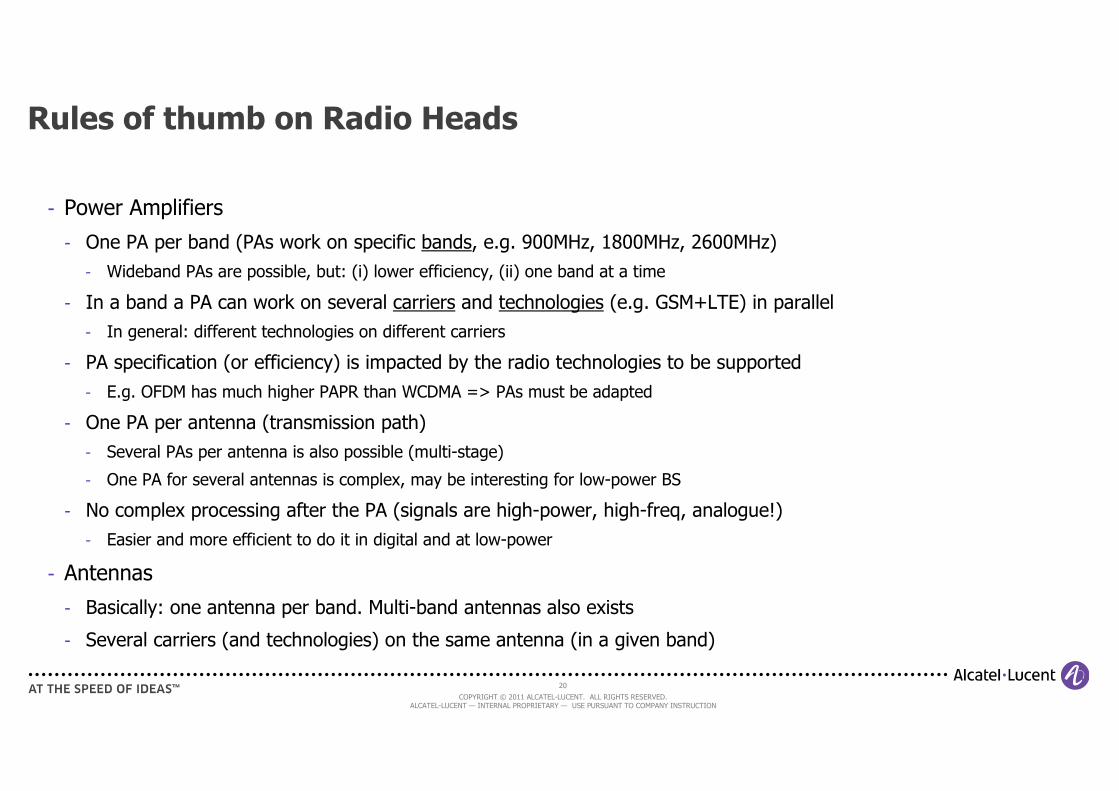
Rules of thumb on Radio Heads
- Power Amplifiers
- One PA per band (PAs work on specific bands, e.g. 900MHz, 1800MHz, 2600MHz)
- Wideband PAs are possible, but: (i) lower efficiency, (ii) one band at a time
- In a band a PA can work on several carriers and technologies (e.g. GSM+LTE) in parallel
- In general: different technologies on different carriers
- PA specification (or efficiency) is impacted by the radio technologies to be supported
- E.g. OFDM has much higher PAPR than WCDMA => PAs must be adapted
- One PA per antenna (transmission path)
- Several PAs per antenna is also possible (multi-stage)
- One PA for several antennas is complex, may be interesting for low-power BS
- No complex processing after the PA (signals are high-power, high-freq, analogue!)
- Easier and more efficient to do it in digital and at low-power
- Antennas
- Basically: one antenna per band. Multi-band antennas also exists
- Several carriers (and technologies) on the same antenna (in a given band)
21
COPYRIGHT © 2011 ALCATEL-LUCENT. ALL RIGHTS RESERVED. ALCATEL-LUCENT — INTERNAL PROPRIETARY — USE PURSUANT TO COMPANY INSTRUCTION
antenna
antenna
cabinet
BB
modem
cooling / fans
PSU
controller - I/O
RH
antenna
RHRH
RH
antenna
cabinet
BB
modem
cooling / fans
PSU
controller - I/O
RH
antenna
RH
antenna
RH
antenna
AAA
AAA
BB
processingBB
processingBBU
Classic BS Remote Radio Head (RRH) Active Antenna Array (AAA)
BB in the cloud (or hoteling) + AAA
RH
antenna
RH
antenna
RH
antenna
All-in-one (e.g. small cells / femtos)
RH
antenna
BB
backhaul
(IP packets)
core
networkfiber optic
with CPRI
fiber optic
with CPRI
fiber optic
with CPRI
coax feeder
RH
antenna
BB
RH
antenna
BB
RH
antenna
BB
BBUBBU
RH
antenna
RH
antenna
jumper
Possible options for grouping functions
PSU = Power Supply Unit
PSU
cabinet
BB
modem
cooling / fans
PSU
controller - I/O
22
COPYRIGHT © 2011 ALCATEL-LUCENT. ALL RIGHTS RESERVED. ALCATEL-LUCENT — INTERNAL PROPRIETARY — USE PURSUANT TO COMPANY INSTRUCTION
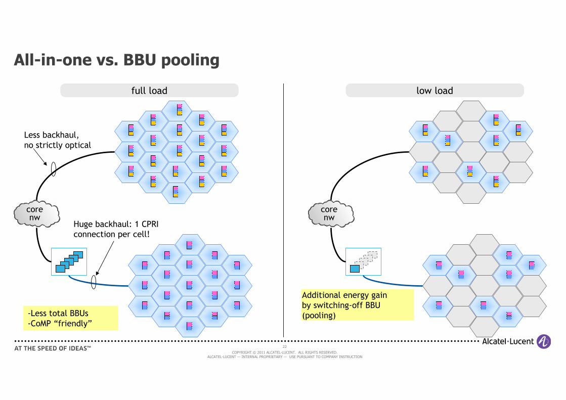
-Less total BBUs
-CoMP “friendly”
All-in-one vs. BBU pooling
corenw
Huge backhaul: 1 CPRI
connection per cell!
Less backhaul,
no strictly optical
Additional energy gain
by switching-off BBU
(pooling)
corenw
full load low load
23
COPYRIGHT © 2011 ALCATEL-LUCENT. ALL RIGHTS RESERVED. ALCATEL-LUCENT — INTERNAL PROPRIETARY — USE PURSUANT TO COMPANY INSTRUCTION
Rules of thumb on BB grouping
• BBU in the cloud (or in large cabinets = hoteling)
- Well adapted for multi-cell processing (like network-MIMO)
- High CPRI BW required + fiber distance limited due to latency limits
- BB pooling => energy savings by matching load with # of active BBUs
• All-in-one
- BB processing can be small, cheap and integrated (e.g. on SoC)
- Best choice for small cells (price constrained)
- Lack of BB pooling. Duplication of “common” functions (e.g. synchronization)
24
COPYRIGHT © 2011 ALCATEL-LUCENT. ALL RIGHTS RESERVED. ALCATEL-LUCENT — INTERNAL PROPRIETARY — USE PURSUANT TO COMPANY INSTRUCTION
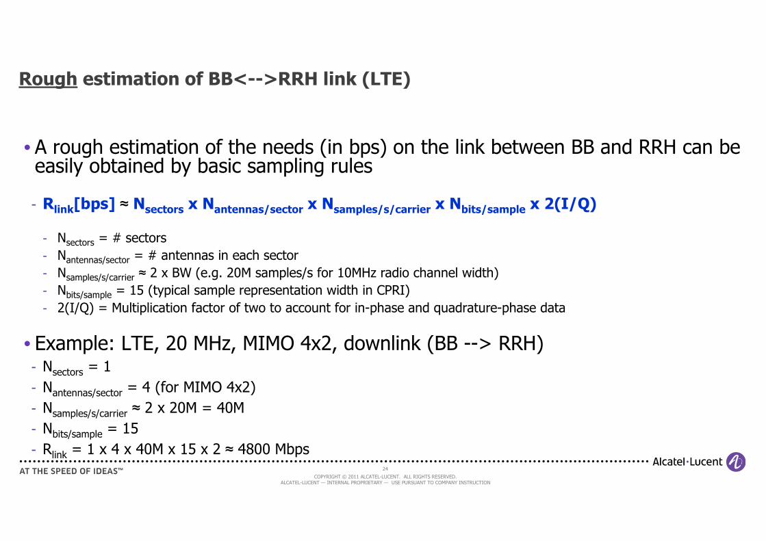
Rough estimation of BB<-->RRH link (LTE)
• A rough estimation of the needs (in bps) on the link between BB and RRH can be easily obtained by basic sampling rules
- Rlink[bps] ≈ Nsectors x Nantennas/sector x Nsamples/s/carrier x Nbits/sample x 2(I/Q)
- Nsectors = # sectors
- Nantennas/sector = # antennas in each sector
- Nsamples/s/carrier ≈ 2 x BW (e.g. 20M samples/s for 10MHz radio channel width)
- Nbits/sample = 15 (typical sample representation width in CPRI)
- 2(I/Q) = Multiplication factor of two to account for in-phase and quadrature-phase data
• Example: LTE, 20 MHz, MIMO 4x2, downlink (BB --> RRH)- Nsectors = 1
- Nantennas/sector = 4 (for MIMO 4x2)
- Nsamples/s/carrier ≈ 2 x 20M = 40M
- Nbits/sample = 15
- Rlink = 1 x 4 x 40M x 15 x 2 ≈ 4800 Mbps
25
COPYRIGHT © 2011 ALCATEL-LUCENT. ALL RIGHTS RESERVED. ALCATEL-LUCENT — INTERNAL PROPRIETARY — USE PURSUANT TO COMPANY INSTRUCTION
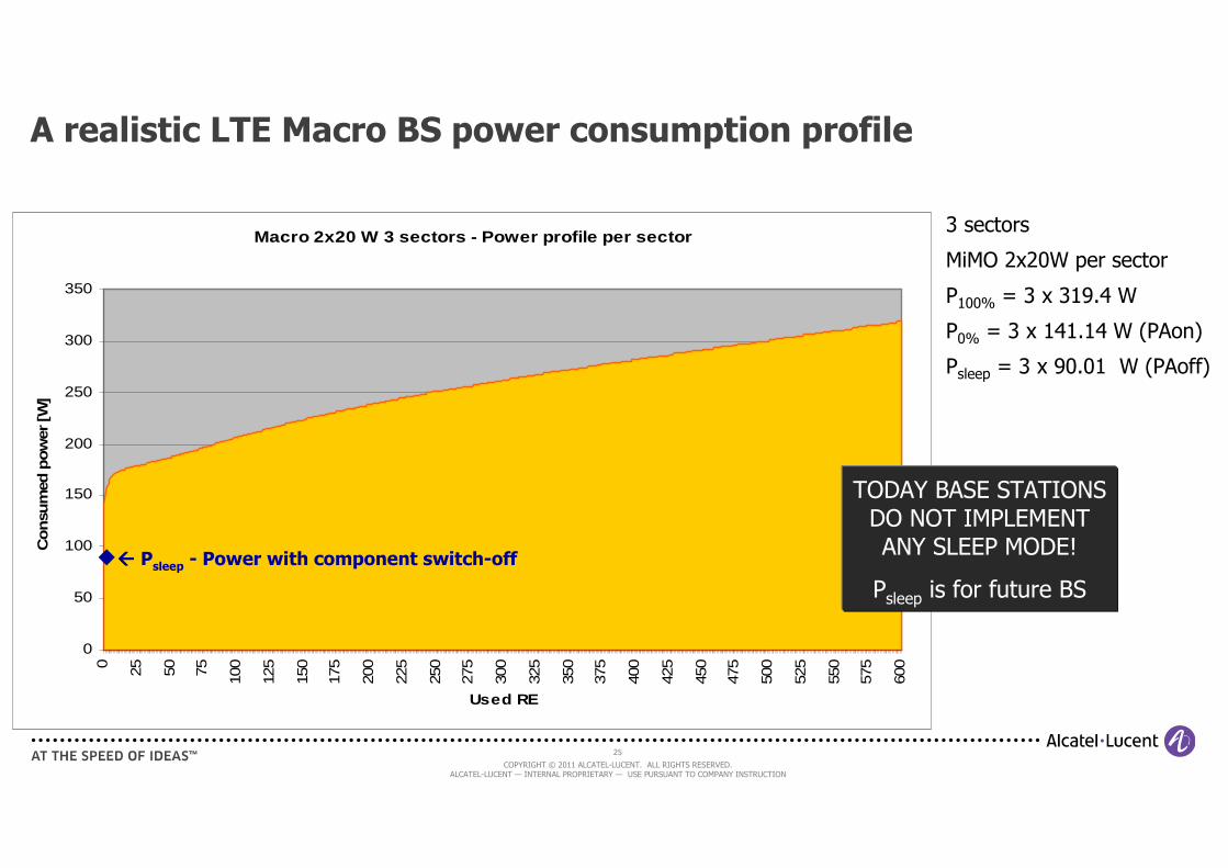
A realistic LTE Macro BS power consumption profile
Macro 2x20 W 3 sectors - Power profile per sector
0
50
100
150
200
250
300
350
0 25 50 75 100
125
150
175
200
225
250
275
300
325
350
375
400
425
450
475
500
525
550
575
600
Used RE
Consu
med
pow
er [W
]
3 sectors
MiMO 2x20W per sector
P100% = 3 x 319.4 W
P0% = 3 x 141.14 W (PAon)
Psleep = 3 x 90.01 W (PAoff)
���� Psleep - Power with component switch-off
TODAY BASE STATIONS DO NOT IMPLEMENT ANY SLEEP MODE!
Psleep is for future BS
26
COPYRIGHT © 2011 ALCATEL-LUCENT. ALL RIGHTS RESERVED. ALCATEL-LUCENT — INTERNAL PROPRIETARY — USE PURSUANT TO COMPANY INSTRUCTION
Cellular Networks plan
• Understanding the cellular networks
• Modeling the cellular network
- BS power consumption models (EARTH, GreenTouch)
- Deployment and models
- Traffic models
• Energy inefficiencies in today cellular networks
• Going green : overview of energy-efficiency improvement techniques
[References]
27
COPYRIGHT © 2011 ALCATEL-LUCENT. ALL RIGHTS RESERVED. ALCATEL-LUCENT — INTERNAL PROPRIETARY — USE PURSUANT TO COMPANY INSTRUCTION
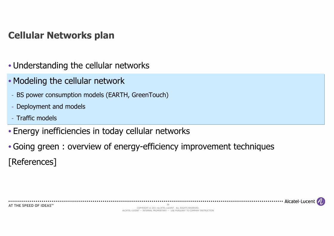
Understanding the wireless channel 1/3
Courtesy of JM Gorce, INRIA
28
COPYRIGHT © 2011 ALCATEL-LUCENT. ALL RIGHTS RESERVED. ALCATEL-LUCENT — INTERNAL PROPRIETARY — USE PURSUANT TO COMPANY INSTRUCTION
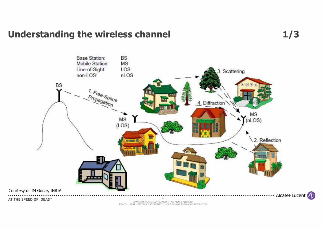
Understanding the wireless channel 2/3
• Wireless channel can be modeled as the sum (in dB) of three factors
- Pathloss (deterministic): attenuation of RF signal due to distance from source (also function of frequency, antenna height, and environment)
- Shadowing (spatial stochastic process, time-stationary (almost), lognormal distribution): function of the environment (as well as frequency, distance, and antenna height) has a random effect due to randomly appearing and disappearing waves (reflections)
- (fast) Fading (sthocastic, highly time-varying): results of multi-path and moving elements in the environment (cars, tree leafs…). Several models: Rayleigh (NLOS), Nakagami (weak LOS), Rice (strong LOS)…
Courtesy of JM Gorce, INRIA
29
COPYRIGHT © 2011 ALCATEL-LUCENT. ALL RIGHTS RESERVED. ALCATEL-LUCENT — INTERNAL PROPRIETARY — USE PURSUANT TO COMPANY INSTRUCTION
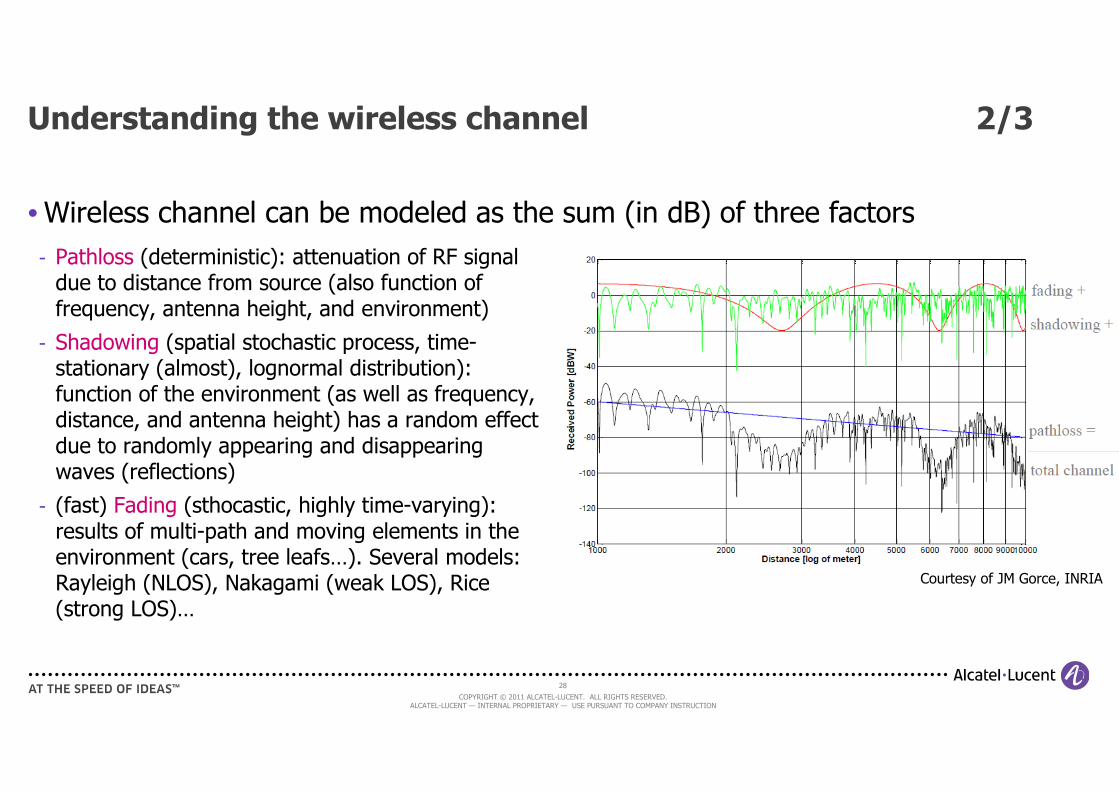
Understanding the wireless channel 3/3
Pathloss and Shadowing are taken into account during cell
planning
Fading is not taken into account at planning, dimensioning phase.
Real-time scheduling and channel-ware techniques take
charge of it
30
COPYRIGHT © 2011 ALCATEL-LUCENT. ALL RIGHTS RESERVED. ALCATEL-LUCENT — INTERNAL PROPRIETARY — USE PURSUANT TO COMPANY INSTRUCTION
Modeling the wireless channel 1/2
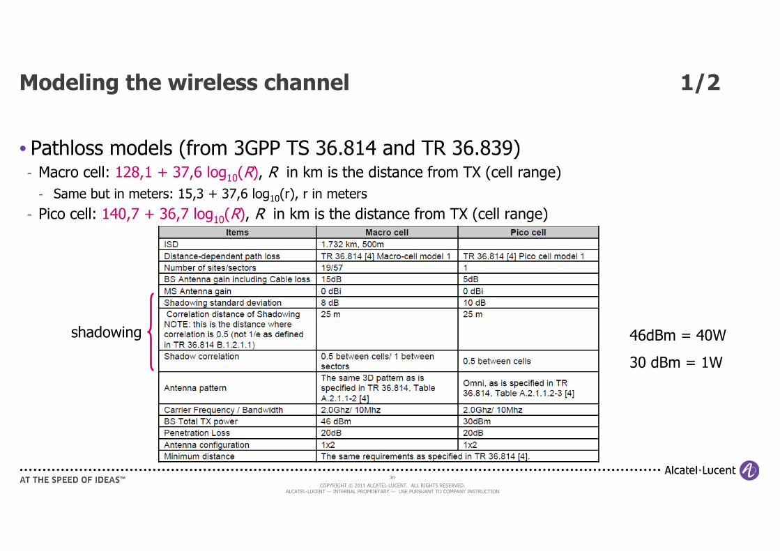
• Pathloss models (from 3GPP TS 36.814 and TR 36.839)- Macro cell: 128,1 + 37,6 log10(R), R in km is the distance from TX (cell range)
- Same but in meters: 15,3 + 37,6 log10(r), r in meters
- Pico cell: 140,7 + 36,7 log10(R), R in km is the distance from TX (cell range)
shadowing 46dBm = 40W
30 dBm = 1W
31
COPYRIGHT © 2011 ALCATEL-LUCENT. ALL RIGHTS RESERVED. ALCATEL-LUCENT — INTERNAL PROPRIETARY — USE PURSUANT TO COMPANY INSTRUCTION
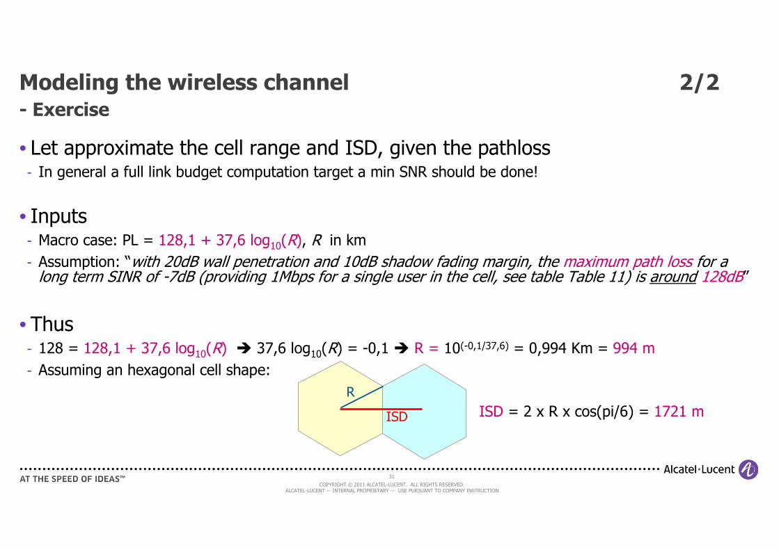
Modeling the wireless channel 2/2- Exercise
• Let approximate the cell range and ISD, given the pathloss- In general a full link budget computation target a min SNR should be done!
• Inputs- Macro case: PL = 128,1 + 37,6 log10(R), R in km
- Assumption: “with 20dB wall penetration and 10dB shadow fading margin, the maximum path loss for a long term SINR of -7dB (providing 1Mbps for a single user in the cell, see table Table 11) is around 128dB”
• Thus- 128 = 128,1 + 37,6 log10(R) � 37,6 log10(R) = -0,1 � R = 10(-0,1/37,6) = 0,994 Km = 994 m
- Assuming an hexagonal cell shape:
ISD = 2 x R x cos(pi/6) = 1721 m ISD
R
32
COPYRIGHT © 2011 ALCATEL-LUCENT. ALL RIGHTS RESERVED. ALCATEL-LUCENT — INTERNAL PROPRIETARY — USE PURSUANT TO COMPANY INSTRUCTION
Macro BS deployment w.r.t. area types
• Typical Inter-Site Distance (ISD) used in simulations
- Dense urban (~10 000 inhabitants/Km2) => ISD = 500 m (site area = 0.22 Km2)
- Urban (~1 000 inhabitants/Km2) => ISD = 1000 m (site area = 0.87 Km2)
- Sub-Urban (~300 inhabitants/Km2) => ISD = 1732 m (site area = 2.6 Km2)
- Rural (~30 inhabitants/Km2) => ISD = 4330 m (site area = 10.4 Km2)
33
COPYRIGHT © 2011 ALCATEL-LUCENT. ALL RIGHTS RESERVED. ALCATEL-LUCENT — INTERNAL PROPRIETARY — USE PURSUANT TO COMPANY INSTRUCTION
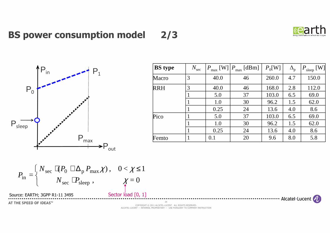
BS power consumption model 1/3
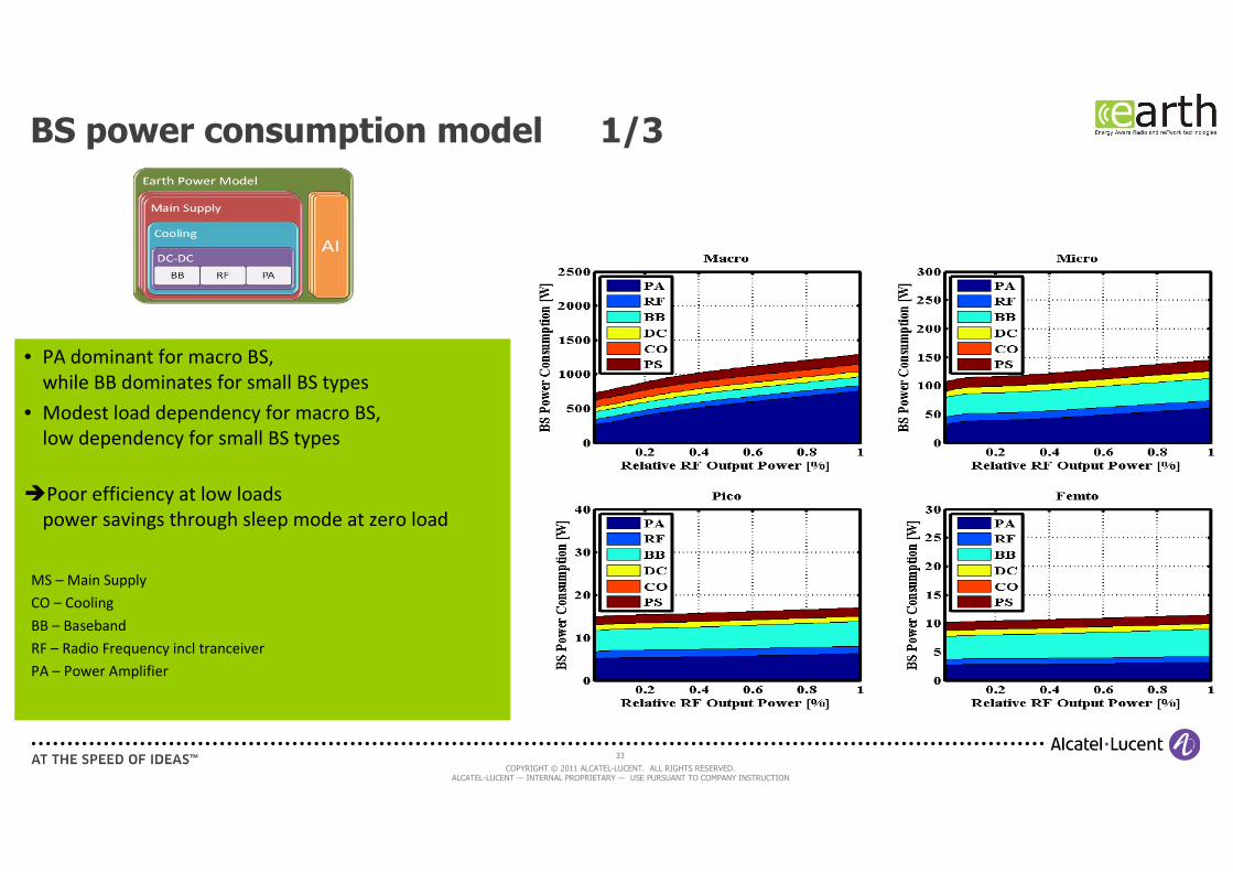
• PA dominant for macro BS,
while BB dominates for small BS types
• Modest load dependency for macro BS,
low dependency for small BS types
�Poor efficiency at low loads
power savings through sleep mode at zero load
MS – Main Supply
CO – Cooling
BB – Baseband
RF – Radio Frequency incl tranceiver
PA – Power Amplifier
34
COPYRIGHT © 2011 ALCATEL-LUCENT. ALL RIGHTS RESERVED. ALCATEL-LUCENT — INTERNAL PROPRIETARY — USE PURSUANT TO COMPANY INSTRUCTION
BS power consumption model 2/3
5.8 8.0 9.6200.1 1 Femto 8.6 4.0 13.6240.25162.01.596.2301.01 69.06.5103.0375.01Pico8.6 4.0 13.6240.25162.01.596.2301.0169.06.5103.0375.01112.0 2.8 168.04640.03 RRH
150.0 4.7 260.04640.03 Macro
Psleep [W] ∆pP0[W] Pmax [dBm] Pmax [W] NsecBS typePin
Pout
Pmax
P0
Psleep
P1
⋅≤∆+⋅0=,
1<0,)(=
sleepsec
maxp0secin χ
χχPN
PPNP
Source: EARTH; 3GPP R1-11 3495 Sector load [0, 1]
35
COPYRIGHT © 2011 ALCATEL-LUCENT. ALL RIGHTS RESERVED. ALCATEL-LUCENT — INTERNAL PROPRIETARY — USE PURSUANT TO COMPANY INSTRUCTION
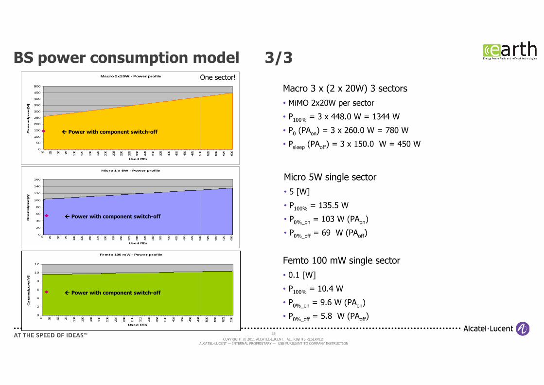
BS power consumption model 3/3
Micro 1 x 5W - Power profile
0
20
40
60
80
100
120
140
160
0 25 50 75 100
125
150
175
200
225
250
275
300
325
350
375
400
425
450
475
500
525
550
575
600
Used REs
Consu
med
power [W]
Macro 3 x (2 x 20W) 3 sectors
• MiMO 2x20W per sector
• P100% = 3 x 448.0 W = 1344 W
• P0 (PAon) = 3 x 260.0 W = 780 W
• Psleep (PAoff) = 3 x 150.0 W = 450 W
���� Power with component switch-off
Micro 5W single sector
• 5 [W]
• P100% = 135.5 W
• P0%_on = 103 W (PAon)
• P0%_off = 69 W (PAoff)
Femto 100 mW single sector
• 0.1 [W]
• P100% = 10.4 W
• P0%_on = 9.6 W (PAon)
• P0%_off = 5.8 W (PAoff)
Femto 100 mW - Power profile
0
2
4
6
8
10
12
0 26 52 78 104
130
156
182
208
234
260
286
312
338
364
390
416
442
468
494
520
546
572
598
Used REs
Consu
med
power
[W
]
���� Power with component switch-off
Macro 2x20W - Power profile
0
50
100
150
200
250
300
350
400
450
500
0 25 50 75 100
125
150
175
200
225
250
275
300
325
350
375
400
425
450
475
500
525
550
575
600
Used REs
Consu
med
pow
er [W
]
���� Power with component switch-off
One sector!
36
COPYRIGHT © 2011 ALCATEL-LUCENT. ALL RIGHTS RESERVED. ALCATEL-LUCENT — INTERNAL PROPRIETARY — USE PURSUANT TO COMPANY INSTRUCTION
Traffic model
37
COPYRIGHT © 2011 ALCATEL-LUCENT. ALL RIGHTS RESERVED. ALCATEL-LUCENT — INTERNAL PROPRIETARY — USE PURSUANT TO COMPANY INSTRUCTION
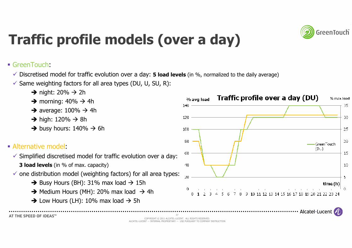
Traffic profile models (over a day)
� GreenTouch:
� Discretised model for traffic evolution over a day: 5 load levels (in %, normalized to the daily average)
� Same weighting factors for all area types (DU, U, SU, R):
� night: 20% � 2h
� morning: 40% � 4h
� average: 100% � 4h
� high: 120% � 8h
� busy hours: 140% � 6h
� Alternative model:
� Simplified discretised model for traffic evolution over a day:
3 load levels (in % of max. capacity)
� one distribution model (weighting factors) for all area types:
� Busy Hours (BH): 31% max load � 15h
� Medium Hours (MH): 20% max load � 4h
� Low Hours (LH): 10% max load � 5h
38
COPYRIGHT © 2011 ALCATEL-LUCENT. ALL RIGHTS RESERVED. ALCATEL-LUCENT — INTERNAL PROPRIETARY — USE PURSUANT TO COMPANY INSTRUCTION
Cellular Networks plan
• Understanding the cellular networks
• Modeling the cellular network
• Energy inefficiencies in today cellular networks
• Going green cellular
[References]
39
COPYRIGHT © 2011 ALCATEL-LUCENT. ALL RIGHTS RESERVED. ALCATEL-LUCENT — INTERNAL PROPRIETARY — USE PURSUANT TO COMPANY INSTRUCTION
Overall challenge
• Cellular networks have been designed to satisfy specific KPIs
- Fast connection
- High spectral efficiency (bit/s/Hz)
- Low consumption of UEs (e.g. native support of idle mode)
- Mobility support of active (hand-over) and idle (relocation) UEs
- Security
- Backward compatibility
• Energy efficiency was not a first priority in the past
- Need to improve mechanisms and equipments not designed for energy efficiency
40
COPYRIGHT © 2011 ALCATEL-LUCENT. ALL RIGHTS RESERVED. ALCATEL-LUCENT — INTERNAL PROPRIETARY — USE PURSUANT TO COMPANY INSTRUCTION
Major sources of energy wasting
• BS hardware components inefficiency (especially the Power Amplifier)
- Today, a top class PA (pre-distorted Doherty) has a power efficiency of around 45% - 50%
- Cooling by air-conditioning is a major source of energy consumption!
• Always-on / emitting cells
- No idle mode for base stations
- Cellular standards (WCDMA/UMTS, LTE…) mandate that BS always signal their presence
• Over deployed network
- Cellular networks are planned and deployed to absorb the highest peak traffic => in general a cellular network is largely under-utilized - Remember the traffic load profile?!!!!
- Co-existence of several independent networks, one for each operator worsen the situation
• Network (and BS) power consumption poorly scales with traffic load
- At low loads, overall energy efficiency worsen!
41
COPYRIGHT © 2011 ALCATEL-LUCENT. ALL RIGHTS RESERVED. ALCATEL-LUCENT — INTERNAL PROPRIETARY — USE PURSUANT TO COMPANY INSTRUCTION
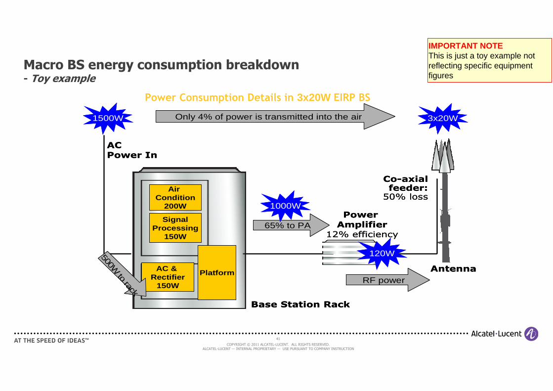
Macro BS energy consumption breakdown- Toy example
Power
Amplifier12% efficiency
Antenna
Base Station Rack
1500W
AC
Power In
AC & Rectifier
150W
SignalProcessing
150W
Air Condition
200W
Platform
Only 4% of power is transmitted into the air 3x20W
3x20W
Co-axialfeeder:50% loss
65% to PA
1000W
RF power
120W500W to rack
Power
Amplifier12% efficiency
Antenna
Base Station Rack
1500W
AC
Power In
AC & Rectifier
150W
SignalProcessing
150W
Air Condition
200W
Platform
Only 4% of power is transmitted into the air 3x20W
3x20W
Co-axialfeeder:50% loss
65% to PA
1000W
RF power
120W500W to rack
Power Consumption Details in 3x20W EIRP BS
IMPORTANT NOTEThis is just a toy example not reflecting specific equipment figures

42
COPYRIGHT © 2011 ALCATEL-LUCENT. ALL RIGHTS RESERVED. ALCATEL-LUCENT — INTERNAL PROPRIETARY — USE PURSUANT TO COMPANY INSTRUCTION
Always emitting cells: the LTE case 1/2
f
t
……
Pilot (Reference Signal)
Scheduling grants (PDCCH)Broadcast General Info (BCH)
Synchronization (PSS/SSS)
Physical Resource Block (PRB)

43
COPYRIGHT © 2011 ALCATEL-LUCENT. ALL RIGHTS RESERVED. ALCATEL-LUCENT — INTERNAL PROPRIETARY — USE PURSUANT TO COMPANY INSTRUCTION
Always emitting cells: the LTE case 2/2
Broadcast signaling used to:
- Signal service availability to mobile terminals (coverage)
- Provide system information allowing UEs to connect to network
- Provide synch signals (in time and frequency)
- Enable UEs to estimate cell quality
- Mobility support
Even when no user traffic 10% -20% of max Txpower for broadcast channels and pilot signals
LTE (5MHz bandwidth)
- Overhead caused by Reference Symbols 5% - 10% (boosting). Proportional to bandwidth!
- Physical control channels up to 14% to 21 %.
- Synchronization and phys BCH overhead not bandwidth dependent.

44
COPYRIGHT © 2011 ALCATEL-LUCENT. ALL RIGHTS RESERVED. ALCATEL-LUCENT — INTERNAL PROPRIETARY — USE PURSUANT TO COMPANY INSTRUCTION
A bit of analysis on BS power consumption
•BS consumption analysis- BBU, PSU, cooling/fans consumption is poorly dependent on cell load- RH: ~60% of its consumption scales with data traffic load
- The remaining ~40% is not dependent on data traffic load- HW consumption - Broadcast channels: continuously emitted (10-15% of RF power) even at 0 load
Coveragetax
cell load [%]
PTOT [W]
0% 100%
PMAX
~0.5 PMAX
IMPORTANT NOTEThis is just a toy example not reflecting specific equipment figures
Toy exampleMacro LTE eNB 2x30W (MIMO 2x2) x 3 sectors
=> PMAX ~ 1200-1500W

45
COPYRIGHT © 2011 ALCATEL-LUCENT. ALL RIGHTS RESERVED. ALCATEL-LUCENT — INTERNAL PROPRIETARY — USE PURSUANT TO COMPANY INSTRUCTION
Cellular Networks plan
• Understanding the cellular networks
• Modeling the cellular network
• Energy inefficiencies in today cellular networks
• Going green cellular
- Taxonomy of energy-efficiency improvement techniques
- Improvements at BS component level
- Improvements at BS level
- Improvement at cell site
- Improvements at network level
[References]

46
COPYRIGHT © 2011 ALCATEL-LUCENT. ALL RIGHTS RESERVED. ALCATEL-LUCENT — INTERNAL PROPRIETARY — USE PURSUANT TO COMPANY INSTRUCTION
A taxonomy

47
COPYRIGHT © 2011 ALCATEL-LUCENT. ALL RIGHTS RESERVED. ALCATEL-LUCENT — INTERNAL PROPRIETARY — USE PURSUANT TO COMPANY INSTRUCTION
Improvements at BS components level
• The majority of research effort is focused on improving power efficiency whilst decreasing amplifier losses
- New materials (e.g. GaN)
- Traffic-aware PAs: ability to change operating point or deactivate drain voltage as function of traffic
- New architectures:
- Switch-Mode PA -> expected efficiency ~ 60%-70% - Envelop-tracking PA: power supply voltage is adjusted in real-time to the required instantaneous output power. It ensures that the PA constantly operates at peak efficiency

48
COPYRIGHT © 2011 ALCATEL-LUCENT. ALL RIGHTS RESERVED. ALCATEL-LUCENT — INTERNAL PROPRIETARY — USE PURSUANT TO COMPANY INSTRUCTION
BB + full radio on chip
BB + (digital) radio on chip
BB on a chip
Integration “on chip” options
CPRIbackhaul
backhaul
processin
g+ A↔
D
analogue
PA/LNA + filters
backhaul
processin
g+ A↔
D
jumper
•“Traditional” approach
• Useful when BB is concentrated in hotel/cloud or
large BTS central offices
• Can be used in loosely integrated “all in one” solution
•Integrates BB + the “digital” part of the radio head
(including DAC and ADC)
• Need external PA/LNA and filters
• Used in “all-in-one” solution (more integrated than
previous one)
• Integrates also the analogue part of the radio head
(i.e. also PA/LNA and filters)
• Can be done only for relatively low-power RF (small
cells)
• Used in “all-in-one” solution

49
COPYRIGHT © 2011 ALCATEL-LUCENT. ALL RIGHTS RESERVED. ALCATEL-LUCENT — INTERNAL PROPRIETARY — USE PURSUANT TO COMPANY INSTRUCTION
Improvements at BS level
• Active cells adapting to traffic load
- Adaptation of used resources in time + Micro-DTX
- Adaptation of used resources in frequency
- Adaptation of BW
- Adaptation of # of transmitting antennas
- Adaptation of # of carriers
- Adaptation of RATs
• Transmission improvements
- Based on different flavor of multi-antenna MIMO
• Idle modes

50
COPYRIGHT © 2011 ALCATEL-LUCENT. ALL RIGHTS RESERVED. ALCATEL-LUCENT — INTERNAL PROPRIETARY — USE PURSUANT TO COMPANY INSTRUCTION
Active cells adapting to traffic load 1/5
BSs account for55% to 80% of the total RAN energy consumption
BSs account for55% to 80% of the total RAN energy consumption
- Power Amplifier designed to be efficient at peak power
- PAs can be “de-activated”in real-time
- Power Amplifier designed to be efficient at peak power
- PAs can be “de-activated”in real-time
Base Stations are the most consuming
equipments in RAN
Base Stations are the most consuming
equipments in RAN
Base Stations are most of the time
poorly loaded
Base Stations are most of the time
poorly loaded
For a BS, it is more efficient to transmit at
full power than at lower power
For a BS, it is more efficient to transmit at
full power than at lower power

51
COPYRIGHT © 2011 ALCATEL-LUCENT. ALL RIGHTS RESERVED. ALCATEL-LUCENT — INTERNAL PROPRIETARY — USE PURSUANT TO COMPANY INSTRUCTION
Active cells adapting to traffic load 2/5
• Adaptation of used resources in time + Micro-DTX
- Group traffic and transmit it in one shot…
- => Transmit at maximum power
- => PA works at best efficiency point
- … then stay silent!
- => Micro-sleep (x00 µs)
- => PA can be deactivated
- Expected performances
- High gains at low load
- > 20% gains during one day
- Standard compatible

52
COPYRIGHT © 2011 ALCATEL-LUCENT. ALL RIGHTS RESERVED. ALCATEL-LUCENT — INTERNAL PROPRIETARY — USE PURSUANT TO COMPANY INSTRUCTION
Active cells adapting to traffic load 3/5
• Adaptation of used resources in frequency
- Concentrate traffic in frequency so that to use less spectrum. Cannot exploit micro-DTX
- No impact on UE
• Adaptation of BW
- Similar to adaptation in frequency, but by explicitly reducing the used BW (LTE available bandwidths: 1.4 MHz, 3 MHz, 5 MHz, 10 MHz, 20 MHz)
- Reduces the number of pilots and energy for signaling
- Not transparent to UE => additional delay, less real-time

53
COPYRIGHT © 2011 ALCATEL-LUCENT. ALL RIGHTS RESERVED. ALCATEL-LUCENT — INTERNAL PROPRIETARY — USE PURSUANT TO COMPANY INSTRUCTION
Active cells adapting to traffic load 4/5
Source: Ambrosy, A.; Blume, O.; Klessig, H.; Wajda, W., "Energy saving potential of integrated hardware and resource management solutions for wireless base stations," Personal Indoor and Mobile Radio Communications (PIMRC), 2011 IEEE 22nd International Symposium on , vol., no., pp.2418,2423, 11-14 Sept. 2011

54
COPYRIGHT © 2011 ALCATEL-LUCENT. ALL RIGHTS RESERVED. ALCATEL-LUCENT — INTERNAL PROPRIETARY — USE PURSUANT TO COMPANY INSTRUCTION
Active cells adapting to traffic load 5/5
• Adaptation of # of transmitting antennas
- Move from e.g. MIMO 4X4 to MIMO 2x2
- This can not happen in a transparent way! Both UE and BS must reconfigure their TRX in order to work correctly
• Adaptation of # of carriers
- Can be used when a BS uses multiple carriers. In that cas the BS can turn-off some of the cariiers and keep the remaining (at least one) on.
- Easy to implement
• Adaptation of RATs
- Can be used when a BS uses multiple air interfaces (multi-RAT, e.g. UMTS + LTE). In that case the BS can turn-off a RAT (e.g. LTE) and keep the other on (e.g. UMTS)
- UEs must be able to use the remaining RAT

55
COPYRIGHT © 2011 ALCATEL-LUCENT. ALL RIGHTS RESERVED. ALCATEL-LUCENT — INTERNAL PROPRIETARY — USE PURSUANT TO COMPANY INSTRUCTION
Transmission improvements: MIMO flavors 1/3
• Multiple-In Multiple-Out exploit several antennas at BS and UE to create independent radio channels (streams)
• Energy efficiency improvements come from
- Higher spectral efficiency
- Reduced RF emission power thanks to beamforming

56
COPYRIGHT © 2011 ALCATEL-LUCENT. ALL RIGHTS RESERVED. ALCATEL-LUCENT — INTERNAL PROPRIETARY — USE PURSUANT TO COMPANY INSTRUCTION
Transmission improvements: MIMO flavors 2/3
• Going to the extreme: massive antenna systems- Use tens of antennas to form extremely focused beams- Antennas can be centralized or distributed. Processing is always centralized- Very high requirements in backhauling!
Spatially distributed antennasMassively co-located antennas
BBprocessing

57
COPYRIGHT © 2011 ALCATEL-LUCENT. ALL RIGHTS RESERVED. ALCATEL-LUCENT — INTERNAL PROPRIETARY — USE PURSUANT TO COMPANY INSTRUCTION
Transmission improvements: MIMO flavors 3/3
• Transmission improvements are effective only on user data, not on signaling!
• Signaling can not take benefit of multi-antenna, as it must transmitted omni-directionally
• A huge amount of pilots is necessary to obtain precise channel state information on each stream!
- At low load the energy efficiency degrades rapidly, and can even be worst that SISO system

58
COPYRIGHT © 2011 ALCATEL-LUCENT. ALL RIGHTS RESERVED. ALCATEL-LUCENT — INTERNAL PROPRIETARY — USE PURSUANT TO COMPANY INSTRUCTION
BS idle modes 1/8
• At low load some Base Stations become unnecessary: they can enter idle-mode
- At conditions that other neighbor Base Stations can absorb the remaining traffic and can also ensure coverage
- Idle modes span from complete switch-off, to just few components switch-off (e.g. PA). No idle mode implemented in current products, but will be available in next generation
- Theoretically very high energy gains can be expected, as cellular networks are over provisioned
• But several problems must be tackled:
- Ensure coverage: turning-off a cell must not result into a coverage hole, or a greater risk of call drop
- Transients: wake-up period depends on what has been deactivated. A cold restart requires several minutes. Faster wake-up is possible at the price of some residual consumption during idle mode
- Wake-up need detection: different solutions have been proposed, from semi-static planned wake-up, to UE detection by different means.

59
COPYRIGHT © 2011 ALCATEL-LUCENT. ALL RIGHTS RESERVED. ALCATEL-LUCENT — INTERNAL PROPRIETARY — USE PURSUANT TO COMPANY INSTRUCTION
BS idle modes 2/8
• Coverage hole risk
- The risk can be very high in case of homogenous (single layer) deployments. The solution is very difficult and requires neighbor cell compensation.
- Similarly, indoor coverage is a big challenge too. Even femtocell may result necessary to ensure coverage is some specific deep indoor places (e.g. basement).
- In case of HetNet the coverage-hole risk is lower, assuming that overlay macro base stations are never put into idle mode. But then gains are reduced!
Empty cellMid/low-loadHigh load

60
COPYRIGHT © 2011 ALCATEL-LUCENT. ALL RIGHTS RESERVED. ALCATEL-LUCENT — INTERNAL PROPRIETARY — USE PURSUANT TO COMPANY INSTRUCTION
BS idle modes 3/8
• Neighbor compensation- Neighbor cells (C1 and C3) enlarge their coverage (by up-tilting the antenna or augmenting the RF power)
in order to cover the area of the idle cell (C2)
- Problem: how to prove to an operator that no coverage hole will be created? At best only statistical margin can be provided (i.e. probability of call drop < some %).
C1 C2 C3

61
COPYRIGHT © 2011 ALCATEL-LUCENT. ALL RIGHTS RESERVED. ALCATEL-LUCENT — INTERNAL PROPRIETARY — USE PURSUANT TO COMPANY INSTRUCTION
61
BS idle modes 4/8– Experimental research
• Data cell = commercial 3G Femtocell (sw + hw modified)
- We implemented a new low-consumption stand-by mode which activates when no UE is connected to the femtocell
- Designed for fast wake-up (few seconds) not for extreme energy savings
- Mainly turns-off the RF part
• Signaling cell = commercial WiFi access point
- Detects UE proximity ( “probe request” from UE) and wakes-up data cell
)))
probe request(wifi)
���� UE requests wake-up ���� 3G femto active���� UE detects the femto
beacon(WiFi)
standby standby active
May go standby
))) )))

62
COPYRIGHT © 2011 ALCATEL-LUCENT. ALL RIGHTS RESERVED. ALCATEL-LUCENT — INTERNAL PROPRIETARY — USE PURSUANT TO COMPANY INSTRUCTION
62
BS idle modes 5/8– Prototype implementation
Signaling cell(WiFi AP)
Data cell (3G
Femto)
Oscillator Heater7%
RF front-end45%
Other48%
Power consumption share
Baseband
Processor
Flash x2
DDR
3G RF
TCXO
heater
ETH SW
3G home
femto
Power
Supply
WiFi AP
Signaling cell(WiFi AP)
Data cell (3G
Femto)
Source: I. Haratcherev, A. Conte, “Practical energy-saving in 3G femtocells”, Green Broadband Access workshop collocated with IEEE ICC 2013

63
COPYRIGHT © 2011 ALCATEL-LUCENT. ALL RIGHTS RESERVED. ALCATEL-LUCENT — INTERNAL PROPRIETARY — USE PURSUANT TO COMPANY INSTRUCTION
BS idle modes 6/8– Analysis
Parts we can switch off (and currently implemented):
• RF is the most beneficial in terms of gain/penalty ratio:- Over 45% electrical power saved
- Low wakeup delay (<0.5 s)
but
- There is need for re-initialization and re-calibration on each wakeup
• TCXO heater also has good gain/penalty ratio:- 7% electrical power saved
- Very easy to switch off/on
but
- TCXO stability might be compromised:
- However our tests show that system still operational
- Other ways to improve stability being investigated
Oscillator Heater7%
RF front-end45%
Other48%

64
COPYRIGHT © 2011 ALCATEL-LUCENT. ALL RIGHTS RESERVED. ALCATEL-LUCENT — INTERNAL PROPRIETARY — USE PURSUANT TO COMPANY INSTRUCTION
BS idle modes 7/8– Analysis
Parts we want to switch off, but we shouldn’t:
• ETH switch would be good to power down (consumes a lot), but no way to wakeup the femto through the backhaul (after)
• Parts of PC302 also can be switched off, but w/ huge redesign penalty:
- Huge re-write of the SW – save/restore context has to be implemented FW-wide
- TCXO frequency control + NTP might have to be re-implemented completely
Parts we don’t need to switch off (low gain, high penalty):
• Memory (P≤0.5W)
• Other:
- Logic (too few, low consumption)
- Oscillators (needed)
- DC/DC converters (normally low quiescent current)

65
COPYRIGHT © 2011 ALCATEL-LUCENT. ALL RIGHTS RESERVED. ALCATEL-LUCENT — INTERNAL PROPRIETARY — USE PURSUANT TO COMPANY INSTRUCTION
65
BS idle modes 8/8– Experimental research - Results
← Power consumption
Transient times →

66
COPYRIGHT © 2011 ALCATEL-LUCENT. ALL RIGHTS RESERVED. ALCATEL-LUCENT — INTERNAL PROPRIETARY — USE PURSUANT TO COMPANY INSTRUCTION
Improvements at cell site
• Use of renewable energy
- Wind turbines and wind mills
- Solar panels
- Always require additional batteries or to be grid-connected
• New cabinets with improved cooling systems
- Small cells allows for passive cooling
- Active research on passive cooling or liquid cooling cabinets also for macro base stations
• Massive adoption of Remote Radio Head (RRH) architectures
- Drastically reduce the losses due to the RF feeder (~ -3db in typical conditions)
• Integration “on chip”, particularly for small cells
- Power consumption reduced thanks to shorter, in chip links between components
- But… risk of not being able anymore of turning-off some of the components (without impacting the others on the same chip)

67
COPYRIGHT © 2011 ALCATEL-LUCENT. ALL RIGHTS RESERVED. ALCATEL-LUCENT — INTERNAL PROPRIETARY — USE PURSUANT TO COMPANY INSTRUCTION
Improvements at network level
• Densification and Heterogeneous Networks
- Small cells and multi-layered deployements
• BS on/off orchestration
- Exploit the network level view to orchestrate the cell on/off
• New architectures
- Move some of the RAN components “into the cloud”, typically the baseband processing
- Requires
- Silent BS: redesign the cellular system

68
COPYRIGHT © 2011 ALCATEL-LUCENT. ALL RIGHTS RESERVED. ALCATEL-LUCENT — INTERNAL PROPRIETARY — USE PURSUANT TO COMPANY INSTRUCTION
Heterogeneous Networks (HetNet) 1/3
• Use of smaller cells to improve capacity under an umbrella macro cell deployment

69
COPYRIGHT © 2011 ALCATEL-LUCENT. ALL RIGHTS RESERVED. ALCATEL-LUCENT — INTERNAL PROPRIETARY — USE PURSUANT TO COMPANY INSTRUCTION
Heterogeneous Networks (HetNet) 2/3
• Why is HetNet green?
• In general densification (i.e. smaller cells) improve the system efficiency by:
- Improving spatial reuse: all the resources (e.g. time slots and subcarriers in LTE) are made available at different places at the same time
- Energy efficiency:
- The number of deployed cell improves proportionally to 1/R2
(half cell size => ~ 4x more cells to cover the same area)
- The transmit power required to get a given received power (Pmin) at distance R is proportional to Ra with a = 3.5 – 4 in urban and suburban environments
PRF PRF
Pmin Pmin
Example
3GPP pathloss for sub-urban PL = 128.1 + 37.6 log10(R)
⇒ PRX (dBm) = PTX (dBm) – [128.1 + 37.6 log10(R)] (in log scale)
⇒ PRX (W) = PTX * 1/1012,81 * 1/R3.76 (in linear scale)

70
COPYRIGHT © 2011 ALCATEL-LUCENT. ALL RIGHTS RESERVED. ALCATEL-LUCENT — INTERNAL PROPRIETARY — USE PURSUANT TO COMPANY INSTRUCTION
Heterogeneous Networks (HetNet) 3/3
• But the goal in not full coverage by small cells: just deploy them in the right spots
- Macro BS offloading
- Typically, Small Cells are deployed at macro cell edge or in particularly crowded spots
• Allows to reduce the requirements on peak traffic that must be handled by the umbrella coverage (macro)
• But to be really energy efficient: small cells must be turned on/off in order to adapt to the traffic load!
- Otherwise, during low load periods, the consumptions of small cells just adds to the macro layer resulting in higher consumption than macro layer only (without a higher data transmission)

71
COPYRIGHT © 2011 ALCATEL-LUCENT. ALL RIGHTS RESERVED. ALCATEL-LUCENT — INTERNAL PROPRIETARY — USE PURSUANT TO COMPANY INSTRUCTION
71
Rethink the signaling 1/4- What’s “wrong” with current signaling?
• The fish-market problem: each Base Station permanently screams (signaling) to advertise its product (connectivity), even when there is no customer (mobile) close-by
• An example with LTE
• The result:
BS C
onsu
mption [
W]
0
200
400
600
800
1000
1200
1400
0% 50% 100%
Cell load [%]
LTE RRH 2x40W 3 sectors 2.6GHz
Coverage tax
t
1 msf
Energy wasting
Inter-cell interferences
Unnecessary RF radiation
Limitations on on/off gains
…
10 % RF power constantly spent for
signaling translates to ~50% (at best) power
consumed to keep signaling “on” even at 0%
load!

72
COPYRIGHT © 2011 ALCATEL-LUCENT. ALL RIGHTS RESERVED. ALCATEL-LUCENT — INTERNAL PROPRIETARY — USE PURSUANT TO COMPANY INSTRUCTION
72
Rethink the signaling 2/4- What Base Stations scream about?
- Assist newly switched-on terminals
- Cell detection and selection, time/frequency synchronization, system
information acquisition
- Assist idle terminals
- Notification of incoming calls (paging)
- Mobility/cell relocation: serving cell quality monitoring, neighbor cell detection
and quality measurement
- Detect tracking/paging area changes
- Assist active terminals
- Data exchange: resource assignments, channel estimation for coherent
demodulation/detection
- Mobility/hand-over: serving cell quality monitoring, neighbor cell detection
and quality measurement
BSs are blind! They don’t know where a new UE will switch-on => this is why they need to scream,
out and loud!
BSs are also “blind” for idle terminals, with an additional challenge: mobility !
This is a very special “signaling”, with the toughest periodicity constraints (e.g. channel coherence
time ~250 us)
Can we redesign better?
Can we stop them screaming all the time?
• Signaling (broadcast info) is highly overloaded in today cellular systems!

73
COPYRIGHT © 2011 ALCATEL-LUCENT. ALL RIGHTS RESERVED. ALCATEL-LUCENT — INTERNAL PROPRIETARY — USE PURSUANT TO COMPANY INSTRUCTION
Rethink the signaling 3/4- Idea 1: Minimal signaling
����activeGet resource assignment (scheduling grants)
����active/idleServing cell quality monitoring
?����active/idleMobility - Neighbor cell detection
active
active
idle
idle
new/idle
New/idle
UE State
��������System Info acquisition
��������Detect tracking/paging area changes
��������Receive paging indication
����Channel estimation for coherent modulation and
demodulation
?����Mobility - Neighbor cell quality measurement
����Cell search & selection
Minimal Signaling
(“idle” cell)
Full Signaling
(active cell)
Functions

74
COPYRIGHT © 2011 ALCATEL-LUCENT. ALL RIGHTS RESERVED. ALCATEL-LUCENT — INTERNAL PROPRIETARY — USE PURSUANT TO COMPANY INSTRUCTION
Rethink the signaling 4/4- Idea 2: Split signaling from data
• Signaling cell: umbrella “macro” cell, always-on
- This cell is dedicated to signaling only
- Must provide means to help locating users!
- Can transmit over a narrow band (more efficient hw)
- Can use a low carrier frequency to ease the propagation
- Can possibly handle some background traffic
• Data cells: small cells, on/off
- Small cells that activate and deactivate according to traffic needs
- If no data to transmit => idle-mode
- Must be activated rapidly (no full switch-off)
• Problem: how to know when and where a UE need a data cell
- Need to locate the user
overlay signaling cell
sleep data cell:
no data / no signalingactive data cell:
data + signaling

75
COPYRIGHT © 2011 ALCATEL-LUCENT. ALL RIGHTS RESERVED. ALCATEL-LUCENT — INTERNAL PROPRIETARY — USE PURSUANT TO COMPANY INSTRUCTION
References
- Luis Suarez, Loutfi Nuaymi and Jean-Marie Bonnin, “An overview and classification of research approaches in green wireless networks”, EURASIP Journal on Wireless Communications and Networking, Volume 2012 (public: http://jwcn.eurasipjournals.com/content/2012/1/142)
- G. Auer, V. Giannini, M. Godor, P. Skillermark, M. Olsson, M. Imran, D. Sabella, M. Gonzales, C. Desset, O. Blume and A. Fehske, "How much energy is needed to run a wireless network?", in IEEE Wireless Communications Magazine, Oct. 2011
- Ambrosy, A.; Blume, O.; Klessig, H.; Wajda, W., "Energy saving potential of integrated hardware and resource management solutions for wireless base stations," Personal Indoor and Mobile Radio Communications (PIMRC), 2011 IEEE 22nd International Symposium on , vol., no., pp.2418,2423, 11-14 Sept. 2011
- I. Haratcherev, A. Conte, “Practical energy-saving in 3G femtocells”, Green Broadband Access workshop collocated with IEEE ICC 2013
- Jingon Joung; Chin Keong Ho; Sumei Sun, "Green wireless communications: A power amplifier perspective," Signal & Information Processing Association Annual Summit and Conference (APSIPA ASC), 2012 Asia-Pacific , vol., no., pp.1,8, 3-6 Dec. 2012
- Conte, A.; Feki, A.; Chiaraviglio, L.; Ciullo, D.; Meo, M.; Marsan, M.A., "Cell wilting and blossoming for energy efficiency," Wireless Communications, IEEE , vol.18, no.5, pp.50,57, October 2011

76
COPYRIGHT © 2011 ALCATEL-LUCENT. ALL RIGHTS RESERVED. ALCATEL-LUCENT — INTERNAL PROPRIETARY — USE PURSUANT TO COMPANY INSTRUCTION
References
- 3GPP R1-11 3495
- www.greentouch.org
- 3GPP TS 36.814 “E-UTRA, Further advancements for E-UTRA physical layer aspects”

77
COPYRIGHT © 2011 ALCATEL-LUCENT. ALL RIGHTS RESERVED. ALCATEL-LUCENT — INTERNAL PROPRIETARY — USE PURSUANT TO COMPANY INSTRUCTION
Optical Networks
Courtesy of Annalisa Morea, Alcatel-Lucent Bell Labs

78
COPYRIGHT © 2011 ALCATEL-LUCENT. ALL RIGHTS RESERVED. ALCATEL-LUCENT — INTERNAL PROPRIETARY — USE PURSUANT TO COMPANY INSTRUCTION
Optical Networks plan
• Motivations
• How to get more energy-efficient networks?
• Sleep modes management
• Elastic optical networks
• Conclusions

79
COPYRIGHT © 2011 ALCATEL-LUCENT. ALL RIGHTS RESERVED. ALCATEL-LUCENT — INTERNAL PROPRIETARY — USE PURSUANT TO COMPANY INSTRUCTION
Motivations
Traffic increases with an annual pace that today is 40% and in 2020 will be around 25%.
What about energy consumption?
Next 10 years: traffic increase of 1200% � 150% of energy increase(1)
(1) C. Lange et al, ECOC2009 paper 5.5.3
2012
70%70%
15%15%
15%15%
Access network
Other
Backbonenetwork
2017
38%38%
42%42%
20%20%
Access network
Other
Backbonenetwork
It is imperative to find more energy efficient backbonesolutions
It is imperative to find more energy efficient backbonesolutions

80
COPYRIGHT © 2011 ALCATEL-LUCENT. ALL RIGHTS RESERVED. ALCATEL-LUCENT — INTERNAL PROPRIETARY — USE PURSUANT TO COMPANY INSTRUCTION
Optical Networks plan
• Motivations
• How to get more energy-efficient networks?
• Sleep modes management
• Elastic optical networks
• Conclusions

81
COPYRIGHT © 2011 ALCATEL-LUCENT. ALL RIGHTS RESERVED. ALCATEL-LUCENT — INTERNAL PROPRIETARY — USE PURSUANT TO COMPANY INSTRUCTION
First step: Observe carried amount of traffic
• Effective traffic requests
• Capacity over-provisioning (unexpected traffic and forecast in a timeframe)
• Traffic recovery
HOW TO GET MORE ENERGY-EFFICIENT NETWORKS?
Expected traffic
Overprovisioning
Resiliency

82
COPYRIGHT © 2011 ALCATEL-LUCENT. ALL RIGHTS RESERVED. ALCATEL-LUCENT — INTERNAL PROPRIETARY — USE PURSUANT TO COMPANY INSTRUCTION
First step: Observe traffic that is transported
• Effective traffic requests
• Capacity over-provisioning (unexpected traffic and forecast in a timeframe)
• Traffic recovery
• Predictable traffic variations (i.e., daily, weekly)
Second step: Observe network management
• Optical networks are quasi-static: all elements are fully powered for the total traffic (without considering daily variations, failure states, …)
HOW TO GET MORE ENERGY-EFFICIENT NETWORKS?
IDEABe able to adapt the network energy consumption to the amount of effective traffic to be carried
Expected traffic
Transported capacityEnergy wastage

83
COPYRIGHT © 2011 ALCATEL-LUCENT. ALL RIGHTS RESERVED. ALCATEL-LUCENT — INTERNAL PROPRIETARY — USE PURSUANT TO COMPANY INSTRUCTION
Traffic-Aware networking denotes network managements where the networkis designed to support the worst-case peak traffic, but both IP and WDM layers consumes according to clients’ demand.
TRAFFIC-AWARE NETWORKING
Introduce different power states (up/idle/down) that can be dynamically reconfigured by the means of a control plane (i.e. GMPLS)
Elastic interfaces can tune their data-rate as a function of the actual transported capacity, thank to modulation-format and/or symbol rate adaptation
ENERGY-AWARENETWORKING

84
COPYRIGHT © 2011 ALCATEL-LUCENT. ALL RIGHTS RESERVED. ALCATEL-LUCENT — INTERNAL PROPRIETARY — USE PURSUANT TO COMPANY INSTRUCTION
Steps for traffic-aware networking
For traffic-aware networking � Adaptive/reconfigurable network elements � Knowledge about future traffic evolution:
Short-term forecasts, prediction algorithms
� Monitoring, management and control
But… any monitoring, control plane information up-date, network reconfiguration means energy consumption
But… any monitoring, control plane information up-date, network reconfiguration means energy consumption
Fully traffic-aware networks are difficult to operate. It becomes important to understand how much adaptive a strategy has to be and estimate the reconfiguration energy impact
Energy is saved if E + ENC < E0Energy is saved if E + ENC < E0

85
COPYRIGHT © 2011 ALCATEL-LUCENT. ALL RIGHTS RESERVED. ALCATEL-LUCENT — INTERNAL PROPRIETARY — USE PURSUANT TO COMPANY INSTRUCTION
Savings depend on:
� Traffic characteristics
� Network reconfiguration approach
We introduce two parameters
� ρ: ideal energy savings as a function of the transported traffic, given a trafficvariation profile and the device power consumption
� η: energy savings provided by ‘traffic-aware’ networking
How to estimate the efficiency of a traffic-aware networking?

86
COPYRIGHT © 2011 ALCATEL-LUCENT. ALL RIGHTS RESERVED. ALCATEL-LUCENT — INTERNAL PROPRIETARY — USE PURSUANT TO COMPANY INSTRUCTION
Efficiency of a ‘traffic-aware’ networking strategyIdeal networks (ρ)
peak
downpeakdown T
PPKtTKPtP
tTKtP
)( )()(
)()(
−=→⋅+=
⋅=
peak
peak
downpeak
down
peak
peak
downpeak
down
peakdown
down
peak
P
TT
PPP
P
tTKT
PPP
TKP
tTKP
P
tPt
−+
=→
⋅−
+=
⋅+⋅+==
ε
ε
)()()(
)(
−⋅
−=−=
peakpeak
downpeak
T
T
P
PP11 ερ
Traffic
Pow
er
Ppeak
Pdown
T0Tpeak
peakref PtP =)(
Powersaved
Power efficiency (ε)
Power savings (ρ)
P: powerT: traffict : time

87
COPYRIGHT © 2011 ALCATEL-LUCENT. ALL RIGHTS RESERVED. ALCATEL-LUCENT — INTERNAL PROPRIETARY — USE PURSUANT TO COMPANY INSTRUCTION
Efficiency of a ‘traffic-aware’ networking strategyIdeal networks (ρ)
Energy savings provided by ‘traffic-aware’ networking depend on:
1)The gap between the average and peak traffic valueslower it is, smaller savings can be achieved
2) The ratio between Ppeak and Pdown
higher it is, major savings are obtained
−⋅
−=
peakpeak
downpeak
T
T
P
PP1ρ
Traffic
Pow
er
Ppeak
Pdown
T0Tpeak
Powersaved
12P: powerT: traffic

88
COPYRIGHT © 2011 ALCATEL-LUCENT. ALL RIGHTS RESERVED. ALCATEL-LUCENT — INTERNAL PROPRIETARY — USE PURSUANT TO COMPANY INSTRUCTION
In a real network there is no linear power-traffic relationship� Traffic has a smaller granularity compared to the devices deployed in a
network
� Network resiliency has to be considered
η gives an idea of how far these strategies are from the ideal case (given by ρ) soas to understand if other energy efficient improvements are possible
Efficiency of a ‘traffic-aware’ networking strategyReal networks (η)
( )peak
peak
peak
peak
P
PP
P
tTPPt
−=→
−= ηη
)()(
P: powerT: traffict : time

89
COPYRIGHT © 2011 ALCATEL-LUCENT. ALL RIGHTS RESERVED. ALCATEL-LUCENT — INTERNAL PROPRIETARY — USE PURSUANT TO COMPANY INSTRUCTION
Optical Networks plan
• Motivations
• How to get more energy-efficient networks?
• Sleep modes management
• Elastic optical networks
• Conclusions

90
COPYRIGHT © 2011 ALCATEL-LUCENT. ALL RIGHTS RESERVED. ALCATEL-LUCENT — INTERNAL PROPRIETARY — USE PURSUANT TO COMPANY INSTRUCTION
SLEEP-MODE MANAGEMENT
The idea is to allow the network management functions and/or network control functions to explicitly provision network devices in:- DownDown state
- IdleIdle state
- UpUp state
An Idle state: the system device is not operational but it stays configured as it is ready for be switched up- The transition delay from the « Idle » state to « Up » state is very short
- The power requirement to maintain a system component in the « Idle » state is minimal
Down Idle Up
b oot -up
s hut down
hibernate
activate
shut down
wake-up
In the following we compare three power management strategies:
� One acts only on optoelectronic (OE) devices� A second acts only on amplifiers on a link� A third acts jointly on OE devices and in-line amplifiers
In the following we compare three power management strategies:
� One acts only on optoelectronic (OE) devices� A second acts only on amplifiers on a link� A third acts jointly on OE devices and in-line amplifiers

91
COPYRIGHT © 2011 ALCATEL-LUCENT. ALL RIGHTS RESERVED. ALCATEL-LUCENT — INTERNAL PROPRIETARY — USE PURSUANT TO COMPANY INSTRUCTION
OE device sleep mode (OESM)
� All OE device are lit-up
No OESM approach
� The number of lit OE devices is minimized
OESM approach
� Lit-up partially filled OE device � Partially filled links are always powered

92
COPYRIGHT © 2011 ALCATEL-LUCENT. ALL RIGHTS RESERVED. ALCATEL-LUCENT — INTERNAL PROPRIETARY — USE PURSUANT TO COMPANY INSTRUCTION
Link sleep mode (LSM)
� All links are lit-up
No LSM approach
� The number of lit links is minimized� Connections do not follow the shortest available path
LSM approach
� Lit-up partially filled links
� Connections follow the shortest available path
3R
� Empty links are powered-off
� Need for further regenerators�Frequent connection reallocations are required

93
COPYRIGHT © 2011 ALCATEL-LUCENT. ALL RIGHTS RESERVED. ALCATEL-LUCENT — INTERNAL PROPRIETARY — USE PURSUANT TO COMPANY INSTRUCTION
The hybrid sleep mode (HSM) approach considers the power management of both OE-devices and links
This approach allows us to understand if more complex approaches provide further energy savings or not.
Hybrid sleep mode (HSM)
� The number of lit links and OE devices is minimized� Connections do not follow the shortest available path
� Empty links are powered-off� Empty OE devices are partially or not powered
� Need for further regenerators� Frequent connection reallocations are required

94
COPYRIGHT © 2011 ALCATEL-LUCENT. ALL RIGHTS RESERVED. ALCATEL-LUCENT — INTERNAL PROPRIETARY — USE PURSUANT TO COMPANY INSTRUCTION
static dynamic static dynamic static dynamic
unprotected 2,35 5,73 28,62 28,62 30,44 33,81 36,74
static dynamic static dynamic static dynamic
unprotected 1,78 4,37 21,86 21,86 22,73 25,82 28,06
static dynamic static dynamic static dynamic
unprotected 8,23 11,62 58,08 58,08 64,62 68,61 74,55
η for T1 Traffic Variations (%)
LSM OESM HSMIDEAL (ρ)
η for T3 Traffic Variations (%)
LSM OESM HSMIDEAL (ρ)
η for T2 Traffic Variations (%)
LSM OESM HSMIDEAL (ρ)
Comparing ρ and ηUnprotected case
LSM approach does not provide enough energysavings

95
COPYRIGHT © 2011 ALCATEL-LUCENT. ALL RIGHTS RESERVED. ALCATEL-LUCENT — INTERNAL PROPRIETARY — USE PURSUANT TO COMPANY INSTRUCTION
static dynamic static dynamic static dynamic
unprotected 2,35 5,73 28,62 28,62 30,44 33,81 36,74
static dynamic static dynamic static dynamic
unprotected 1,78 4,37 21,86 21,86 22,73 25,82 28,06
static dynamic static dynamic static dynamic
unprotected 8,23 11,62 58,08 58,08 64,62 68,61 74,55
η for T1 Traffic Variations (%)
LSM OESM HSMIDEAL (ρ)
η for T3 Traffic Variations (%)
LSM OESM HSMIDEAL (ρ)
η for T2 Traffic Variations (%)
LSM OESM HSMIDEAL (ρ)
Comparing ρ and ηUnprotected case
� OESM does not take advantages of reconfiguration possibility;� HSM operating without reconfiguration slightly improves OEDM

96
COPYRIGHT © 2011 ALCATEL-LUCENT. ALL RIGHTS RESERVED. ALCATEL-LUCENT — INTERNAL PROPRIETARY — USE PURSUANT TO COMPANY INSTRUCTION
static dynamic static dynamic static dynamic
unprotected 2,35 5,73 28,62 28,62 30,44 33,81 36,74
static dynamic static dynamic static dynamic
unprotected 1,78 4,37 21,86 21,86 22,73 25,82 28,06
static dynamic static dynamic static dynamic
unprotected 8,23 11,62 58,08 58,08 64,62 68,61 74,55
η for T1 Traffic Variations (%)
LSM OESM HSMIDEAL (ρ)
η for T3 Traffic Variations (%)
LSM OESM HSMIDEAL (ρ)
η for T2 Traffic Variations (%)
LSM OESM HSMIDEAL (ρ)
Comparing ρ and ηUnprotected case
� HSM provides at least 6% more savings than OEDM, because low traffic profile � +10% of further savings are observed for HSM with dynamic reconfiguration
Traffic
profile
Average
traffic
T1 15%
T2 60%
T3 70%

97
COPYRIGHT © 2011 ALCATEL-LUCENT. ALL RIGHTS RESERVED. ALCATEL-LUCENT — INTERNAL PROPRIETARY — USE PURSUANT TO COMPANY INSTRUCTION
static dynamic static dynamic static dynamic
1:1 protected 3,03 6,5 50,94 50,94 53,49 56,58 36,74
static dynamic static dynamic static dynamic
1:1 protected 1,78 5,06 47,8 47,8 49,07 52,05 28,06
static dynamic static dynamic static dynamic
1:1 protected 9,58 12,79 64,61 64,61 73,41 76,32 74,55
η for T1 Traffic Variations (%)
LSM OESM HSMIDEAL (ρ)
η for T3 Traffic Variations (%)
LSM OESM HSMIDEAL (ρ)
η for T2 Traffic Variations (%)
LSM OESM HSMIDEAL (ρ)
Comparing ρ and η1:1 Protected case
Higher savings are observed because protection means twopaths per demand and network get empty easier

98
COPYRIGHT © 2011 ALCATEL-LUCENT. ALL RIGHTS RESERVED. ALCATEL-LUCENT — INTERNAL PROPRIETARY — USE PURSUANT TO COMPANY INSTRUCTION
static dynamic static dynamic static dynamic
1:1 protected 3,03 6,5 50,94 50,94 53,49 56,58 36,74
static dynamic static dynamic static dynamic
1:1 protected 1,78 5,06 47,8 47,8 49,07 52,05 28,06
static dynamic static dynamic static dynamic
1:1 protected 9,58 12,79 64,61 64,61 73,41 76,32 74,55
η for T1 Traffic Variations (%)
LSM OESM HSMIDEAL (ρ)
η for T3 Traffic Variations (%)
LSM OESM HSMIDEAL (ρ)
η for T2 Traffic Variations (%)
LSM OESM HSMIDEAL (ρ)
Comparing ρ and η1:1 Protected case
� η>ρ !� Traffic variation does not account for the protection redondancy

99
COPYRIGHT © 2011 ALCATEL-LUCENT. ALL RIGHTS RESERVED. ALCATEL-LUCENT — INTERNAL PROPRIETARY — USE PURSUANT TO COMPANY INSTRUCTION
Energy-efficient solutions are mandatory due:� The expected traffic growth
� The increase of energy cost
� The growth of the network infrastructure
Many traffic-aware networking have been presented in the literature, we have presented here two parameters ρ and η for comparing them
The best ‘traffic-aware’ networking is the one providing higher savings with fewerreconfigurations� In this work it is the optoelectronic sleep mode (OESM) one
Sleep mode - Conclusions

100
COPYRIGHT © 2011 ALCATEL-LUCENT. ALL RIGHTS RESERVED. ALCATEL-LUCENT — INTERNAL PROPRIETARY — USE PURSUANT TO COMPANY INSTRUCTION
Optical Networks plan
• Motivations
• How to get more energy-efficient networks?
• Sleep modes management
• Elastic optical networks
• Conclusions

101
COPYRIGHT © 2011 ALCATEL-LUCENT. ALL RIGHTS RESERVED. ALCATEL-LUCENT — INTERNAL PROPRIETARY — USE PURSUANT TO COMPANY INSTRUCTION
Elastic networks Modulation-format adaptation
Trade-off between reach and capacity
�Format-adaptation allows the bypass of unnecessary opto-electronic regeneration at off-peak hours
0
800
1600
2400
3600
-3 -2 -1 0 1 2 3 4 5 6
Input Power Per Channel (dBm)
Reach (km)
0
800
1600
2400
3600
-3 -2 -1 0 1 2 3 4 5 6
Input Power Per Channel (dBm)
Reach (km)
25Gb/s SP-BPSK
50Gb/s PDM-BPSK
75Gb/s PS-QPSK
100Gb/sPDM-QPSK
25Gb/s SP-BPSK
50Gb/s PDM-BPSK
75Gb/s PS-QPSK
100Gb/sPDM-QPSK
Tx Rx Tx
100Gb/s
100G PDM-QPSK 100G PDM-QPSK
100Gb/s50Gb/s 50Gb/s
50Gb/s PDM-BPSK
zzz…
Rx
25Gb/s 75Gb/s50Gb/s 100Gb/s
Simulation set-up:− No-DM− SMF− 50GHz grid
Energy savings comes only if sleep-mode is implemented!

102
COPYRIGHT © 2011 ALCATEL-LUCENT. ALL RIGHTS RESERVED. ALCATEL-LUCENT — INTERNAL PROPRIETARY — USE PURSUANT TO COMPANY INSTRUCTION
50G PDM-QPSK 50G PDM-QPSK
• Symbol-rate adaptation has very little impact on optimal reach!
• Dynamic voltage and frequency scaling (DVFS) tunes the voltage to the requested operating clock-rate (R) � Energy consumption: TSP: 186 + 164 x (R/28)3
Reg: 141 + 273 x (R/28)3
Elastic networks Symbol-Rate Adaptation
0
400
800
1200
1600
-3 -2 -1 0 1 2 3 4 5 6
Input Power Per Channel (dBm)
Reach (km
) 100Gb/s(28Gbaud)
75Gb/s
(21Gbaud)
50Gb/s
(14Gbaud)
25Gb/s
(7Gbaud)
25Gb/s 75Gb/s50Gb/s 100Gb/s
Simulation set-up:− No-DM− SMF− 50GHz grid
SMF50GHz grid
Tx Rx Tx
100G PDM-QPSK 100G PDM-QPSK
100Gb/s 100Gb/s50Gb/s 50Gb/s
Rx

103
COPYRIGHT © 2011 ALCATEL-LUCENT. ALL RIGHTS RESERVED. ALCATEL-LUCENT — INTERNAL PROPRIETARY — USE PURSUANT TO COMPANY INSTRUCTION
Network scenario
European network11 nodes, 17 bi-directional links
Network conditions 32 wavelengths per link
100Gb/s channels
Traffic assumption Unprotected IP traffic - uniform distributed
10Gb/s line cards on the IP router
Average request capacity is a fraction of the transponder capacity
In/Out: 0.27 and 0.57
Energy consumption
100Gb/s PDM-QPSK transponder: 350 W; 100Gb/s rate-adaptive TSP: 186 + 164 x (R/28)3
regenerator: 414W Reg: 141 + 273 x (R/28)3
10Gb/s line cards 15W/Gb/s (router for traffic processing and that of the line cards)
Reference network
Static 100Gb/s network (no power managed)
Multi-layer (IP-o-WDM) dimensioning based on ILP (Integer Linear Programming) formulation
60%

104
COPYRIGHT © 2011 ALCATEL-LUCENT. ALL RIGHTS RESERVED. ALCATEL-LUCENT — INTERNAL PROPRIETARY — USE PURSUANT TO COMPANY INSTRUCTION
Results
Savings due to energy-aware strategies Required OE-devices
OE
-de
vic
en
um
be
r
0
20
40
60
80
100
120
SM SR
SR
-SM
MF
0
5
10
15
20
25
30
35
En
erg
ysa
vin
gs
(%)
SM SR
SR
-SM
MF
In/Out =0.27
In/Out =0.57
SM SR SR-SM MF
Energy savings -18% -27% -30% -20%
OE-devices 0 +28/48% +28/48% 0
Symbol-Rate adaptation is more energy efficient…Symbol-Rate adaptation is more energy efficient…
SM = Sleep-mode; SR = Symbol-Rate; MF = Modulation FormatAdaptation Adaptation
…but this solution is not cost-efficient!…but this solution is not cost-efficient!
OE-device for staticscenario

105
COPYRIGHT © 2011 ALCATEL-LUCENT. ALL RIGHTS RESERVED. ALCATEL-LUCENT — INTERNAL PROPRIETARY — USE PURSUANT TO COMPANY INSTRUCTION
Results
In/Out =0.27
In/Out =0.57
SM SR SR-SM MF SR-TO SR-SM-TO
Energy savings -18% -27% -30% -20% -26% -28%
OE-devices 0 +28/48% +28/48% 0 0 0
SR
-S
M-T
O
… jointly with on/off solutions only improves of ~2% the estimated savings… jointly with on/off solutions only improves of ~2% the estimated savings
TO: max number of resources constrained to the required by the reference networkTO: max number of resources constrained to the required by the reference network
Savings due to energy-aware strategies Required OE-devices
OE
-de
vic
en
um
be
r
0
20
40
60
80
100
120
SM SR
SR
-SM
MF
0
5
10
15
20
25
30
35
En
erg
ysa
vin
gs
(%)
SM SR
SR
-SM
MF
SR
-TO
SR
-TO
SM = Sleep-Mode; SR = Symbol-Rate; MF = Modulation Format; TO = Trade-OffAdaptation Adaptation
Symbol-Rate adaptation is always more energy efficient…Symbol-Rate adaptation is always more energy efficient…
SR
-S
M-T
O

106
COPYRIGHT © 2011 ALCATEL-LUCENT. ALL RIGHTS RESERVED. ALCATEL-LUCENT — INTERNAL PROPRIETARY — USE PURSUANT TO COMPANY INSTRUCTION
Due to the increase of traffic, telecom operators seek for novel network design strategies which represent a good compromise between energy and cost (trade-off on the number of used resources).
Energy-aware networking is the solution providing more energy-efficient networks
We compare and combine two different approaches: sleep-mode and elastic networking� Sleep-Mode alone provides 18% of energy savings
� Modulation-Format provides 20% of energy savings
� Symbol-rate adaptation provides 26% of energy savings
� Sleep-Mode joint with Symbol-rate adaptation only 2% of further gains
Elastic networks - Conclusions

107
COPYRIGHT © 2011 ALCATEL-LUCENT. ALL RIGHTS RESERVED. ALCATEL-LUCENT — INTERNAL PROPRIETARY — USE PURSUANT TO COMPANY INSTRUCTION
References
- C. Lange, “Energy-related Aspects in Backbone Networks”, ECOC 2009 (slides), http://conference.vde.com/ecoc-2009/programs/documents/ws4_lange_ws_bb_final.pdf
- A. Morea, G. Rizzelli, and M. Tornatore, "On the Energy and Cost Trade-Off of Different Energy-Aware Network Design Strategies," in Optical Fiber Communication Conference/National Fiber Optic Engineers Conference 2013, OSA Technical Digest (online) (Optical Society of America, 2013), paper OM3A.4.

108
COPYRIGHT © 2011 ALCATEL-LUCENT. ALL RIGHTS RESERVED. ALCATEL-LUCENT — INTERNAL PROPRIETARY — USE PURSUANT TO COMPANY INSTRUCTION
THANK YOU

109
COPYRIGHT © 2011 ALCATEL-LUCENT. ALL RIGHTS RESERVED. ALCATEL-LUCENT — INTERNAL PROPRIETARY — USE PURSUANT TO COMPANY INSTRUCTION
Base Station Energy Efficiency assessmentLab tests
• ETSI TS102706 V1.3.1 (June 2013)- Measurement Method for Energy Efficiency of Wireless Access Network Equipment
- Reference for European operators, European regulators (BB Code of Conduct) and ITU
- Main metrics:
o Energy consumption (W) at Busy Hour (BH), Medium Load (ML), Low Load (LL) and Average@LL (W)
o Energy Efficiency for coverage (km²/W)
o Energy Efficiency for capacity (users/W for GSM and kbit/J for WCDMA/LTE)
• ETSI TR103116 V1.1.1 (Oct 2012)- Provides practical application and maintenance of the TS 102706
- TS 102706 V1.3.1 (minor updates) expected mid-2013 and V1.4.1 (major updates) expected end-2013
• ATIS 0600015.06.2011 (Nov 2011)- Methodology for measurement & reporting of RBS metrics
- Reference for US customers (Verizon, AT&T…)
- Metrics : TEER (kbps/W) and RF Efficiency ratio (%)
- Issue 2 expected in 2014 with process simplifications

110
COPYRIGHT © 2011 ALCATEL-LUCENT. ALL RIGHTS RESERVED. ALCATEL-LUCENT — INTERNAL PROPRIETARY — USE PURSUANT TO COMPANY INSTRUCTION
Mobile Network Energy Efficiency assessmentStandard development (ongoing)
•ETSI work item EEPS005- ETSI Specification (ES)- Use caseso Generic cluster assessment
o Live network assessment
o Global network modeling
- Scheduleo Sept 2012: start
o June 2013: early draft
o Sept 2014: stable draft
o Feb 2015: TB approval
- Metricso MNEE: mobile network energy efficiency
o MNPD: mobile network performance delivered
o MNEC: mobile network energy consumption
o MNEE = MNPD / MNEC
- Backgroundo Leverage TR103117 guidelines
o Scope: GSM, UMTS & LTE RAN (incl. MBH)
o Metrics/KPIs based on throughput and/or number of users within a range of Quality of Service/Quality of Experience
o Analyse pros/cons of methods based on nodes counters or on test users
- Liaisons with 3GPP SA5 and RAN2o TS32.425 Performance measurements
• §4.4 throughput and active users• § 4.5 transmitted power• § 4.10 CQI distribution
o TS36.314 Layer 2 – Measurements• Used for network management• § 4.1.3.1 Number of active users• § 4.1.6.1 Scheduled IP throughput in DL
independent of traffic patterns and packet size• § 4.1.7.1 Measures IP throughput over Uu in DL• § 4.1.8.1 Data Volume for MDT in DL.

111
COPYRIGHT © 2011 ALCATEL-LUCENT. ALL RIGHTS RESERVED. ALCATEL-LUCENT — INTERNAL PROPRIETARY — USE PURSUANT TO COMPANY INSTRUCTION
Mobile Network Energy Efficiency MetricsEarly draft proposal (June 2013)
• The Mobile Network Energy Consumption (MNEC) is the sum of the energy consumption of equipment included in the MN under investigation. MNEC is generally expressed in MWh/Y
MNEC = Σi (BSEC)i + Σj (BHEC)j (1)
• The Mobile Network Performance Delivered (MNPD) is the performance indicator of the MN under investigation relevant for energy efficiency assessment. MNPD is defined as the datavolumehandled by the equipment of the mobile network under investigation during the time frame of the energy consumption assessment.
MNPD = Σi (BSPD)i + Σj (BHPD)j (2)
• Mobile Network Data Energy Efficiency (MNDEE) is the ratio between the performance indicator (MNPD) and the energy consumption (MNEC) when assessed during the same time frame. MNEE is generally expressed in kbit/J.
MNDEE = MNPD / MNEC (3)
• Mobile Network Coverage Energy Efficiency (MNCEE) is the ratio between the area covered by the BS in the MN under investigation and the energy consumption (MNEC) when assessed during one year. MNEE is generally expressed in km²/MWh per year.
MNCEE = CoA / MNEC (4)


![DOSCH DESIGNDosch Textures: Sci-Fi Textures ases—MSll aril] —oa ages enb—Ol celliJâ eges enb—ao erib 03 enb —enl) 01 CSI asas—MSll enb—u; ages enb—ort asas DI EIOOL](https://img.dokumen.tips/doc/110x75/5f8bc80253e84874430eba83/dosch-design-dosch-textures-sci-fi-textures-asesamsll-aril-aoa-ages-enbaol.jpg)