Embed Size (px)
Citation preview

International Journal of Mechanical & Mechatronics Engineering IJMME-IJENS Vol:17 No:04 52
173904-5656-IJMME-IJENS © August 2017 IJENS I J E N S
Green Weight-Lifting Machine Using Gear-Shifting
Mechanism and A Power Generator
Vinesh Thiruchelvam
School of Engineering,
Asia Pacific University,
Kuala Lumpur, Malaysia.
E-mail: [email protected]
Syed Abdullah Medni
School of Engineering,
Asia Pacific University,
Kuala Lumpur, Malaysia.
E-mail: [email protected]
Cleopatra Musa Yasin Hammad
School of Engineering,
Asia Pacific University,
Kuala Lumpur, Malaysia.
E-mail: [email protected]
Abstract— The growth of innovative renewable energy sources is
a worldwide consideration due to the high power demand and the
harmful influence of conventional sources of energy to the
environment. Besides the solar and wind energy, fitness facilities
around the world employed the cardiovascular machines such as
elliptical trainer to generate energy throughout the exercise. As a
further utilization of the gymnasium’s machines, the proposed
project developed a green weight-lifting machine with high
torque generator and gears-shifting mechanism to generate
electricity during the user’s workout. The mechanical design of
the machine focused in altering the linear motion by the user to
rotational motion via pulleys and wheel, which then converted by
the generator to electricity. The power stabilization system was
also introduced to amplify and stable the generator’s output
power with the help of capacitor, voltage converters, and
Arduino controller. Each gear level in the gears-shifting
mechanism represents specific kilograms to be lifted, which were
theoretically derived and then compared with the testing results
where 96.7% accuracy was successfully achieved. The conducted
six tests were designed to find out the lifted kilograms and
generated power in four exercises with six levels of gears.
Index Term– Arduino Controlling, Gears-Shifting Mechanism,
Generator.
I. INTRODUCTION
The importance of energy and its usage has arose in all
around the world, and due to this factor there is an essential
need to create the new technique for the conservation of
energy and power generation that causes least influences on
environment. Therefore, there are some auspicious areas of
application for human power in developing sections where
electric power is not affordable or not obtainable. Similarly at
the most fitness facilities, there are some unused potential for
the requirement of binding the human power also.
In early 2007, the research was started by the fitness
facilities regarding the conversion of human power to
electricity. Initially the first gym that was established to
integrate the human powered machines was California Fitness
facility in Hong Kong, by Lucien Gambarota the French
inventor and the Doug Woodring the entrepreneur. The
program was called “Powered by YOU” which diverts and
converts the excessive energy generated by the members on
13step cycling and cross training machines to the power
lighting fixtures in the gym. Moreover, The Dixon Recreation
Center at Oregon State University (OSU) by Clearwater based
on the Florida Company known to be ReRev that retrofitted in
2008 and 2009. The company diverts the excessive energy
generated by the clients to the electric grid, by retrofitting 22
elliptical machines at OSU. Furthermore, the company states
in the website that “An elliptical machine in regular use at a
gym using ReRev technology will generate one kilowatt-hour
of electricity every two days” (Haji, Laa & Agogino, 2010) [1].
The stability and position of the business plan plays a vital
role in order to evaluate the possibility ratio of execution of
gymnasium’s green technology. By taking this into
consideration and by understanding the responsibility we have
towards our environment, the Green Weight-Lifting Machine
is introduced as a unique opportunity to utilize the human
energy for the good of our environment. The implementation
of green weight lifting machines can be housed within a gym
and used to offset the gym’s energy requirement besides the
cardiovascular machines.
II. METHODOLOGY
Generator Connection: Fig 1 shows the block diagram of
generator connection. The high torque 50W generator is
connected to the weight-lifting machine with the help of
pulley which is connected to the shaft of the generator. The
pulley is connected to the wheel with the help of belt. A 10cm
diameter pulley is connected to the shaft of the generator and
the wheel of 17 inches which is attached to the pulley through
120cm long belt. When the user is working out, the liner
motion produce during the workout is converted to the
rotational motion with the help of pulleys. The string which is
connected to the chain on the other side will allow the wheel
to rotate which will then rotate the pulley connected to the
shaft of high torque generator with the help of belt. Hence the
high torque PM generator will generate electricity. The one
cycle of the 17 inches wheel is equal to the 5 cycles of 10cm
pulley which is connected to the generator. The reason of
using a pulley of large diameter is to limit the maximum force
applied by the user at the smallest gear and to prevent it from
any damage which can be caused due to high tension on the
string and pulleys.

International Journal of Mechanical & Mechatronics Engineering IJMME-IJENS Vol:17 No:04 53
173904-5656-IJMME-IJENS © August 2017 IJENS I J E N S
Fig. 1. Generator Connection Block Diagram
Gears-Shifting Mechanism: Another main objective of the
project is the modified gears shifting mechanism (Fig 2). The
gear-shifting mechanism consists of six levels of gears in
order to have more weights options. The moving of the gear-
shifter is dependent on the metal string attached to it. When
the metal string of the gear shifter is pulled, it allows the
shifter to move inside towards the bigger gear. In this way the
shifter changes the position of the chain to different gears.
Each gear has approximately 2kgs of difference between
them; the first gear allows the user to apply 21kg, whereas the
last gear allows 32kg.
Fig 2. Proposed Gears-Shifting Mechanism
The main purpose of modifying the weight lifting machine
is to generate electricity from the power exerted by the person
during his/her workout. The current weight lifting is modified
in such a way that it converts the linear motion to the
rotational motion with the help of some pulleys and chain,
which is needed at the end to rotate the shaft of the generator,
the overall 2-D mechanical design is shown in the Fig 3. The
reason of developing a suitable gear-shifting mechanism is to
control the intensity of workout, meaning that the force
applied by the person can be controlled without changing or
using the extra weights.
The gears are adjustable and are connected to a wheel. The
machine will rotate the wheel through the gears only in
clockwise direction, whereas the anticlockwise direction will
be free. The spring is attached to the gears-shifting mechanism
in order to support the gear shifter. It is connected to give
more tension on the chain to avoid it to come off the gear.
Power Stabilization System: The block diagram of the
designed power stabilization system is shown in Fig 4. The
Arduino Uno operates as a controller to monitor and control
two circuits in the power optimization system. The program
controls the source of supplying to the system by capacitor
voltage status. The generated output voltage of generator is
connected to the voltage booster. The voltage booster has an
ability to boost the voltage from 4V DC to the 35V DC with
the maximum power of 100W depending on the input current.
This voltage booster is connected in parallel to the capacitor of
24V 3F and voltage sensor 1 which to sense the voltage level
in the capacitor. The Arduino is also controlling the Stable
mode of the circuit that is implemented to exercise easily
without any distortion, and activated when turning the switch
ON (Stable Mode Switch). This is done because the generator
requires more torque to generate enough voltage to turn on the
voltage booster. Once the voltage booster is turned on then the
rotating torque of the generator gets low as the constant flow
of the voltage takes place to boost and charge the capacitor.
To overcome the problem in changing the torque of the
generator, Stable Mode is introduced which is done by taking
the minimum voltage from external source to turn on the
voltage booster and once it turned on the constant voltage is
supplied by the generator.
Fig. 3. Green Weight-Lifting Machine 2-D Design
Fig. 4. Designed Power Stabilization System
Weights Theoretical Derivation: In the testing section, six
gears levels in the gears-shifting mechanism were tested. As
mentioned before, each gear will allow the user to lift specific
amount of kilograms. The lifted kilograms by each gear were
derived theoretically by using engineering fundamentals
related to the mechanical field. Further, the derived parameters
were compared to the actual kilograms displayed on the
attached weight’s meter of the developed weight-lifting
machine design.
Table 1 includes the radiuses in centimeters for each gear
and the wheel which are used to derive the required
parameters. First, it is required to find the torque required to
rotate the gear (τG) by the DC generator. As the radiuses of
gears and wheel are given, and assuming both gear and wheel
have similar speed, no slip and no power losses, the torque can
be found using the ratio of gear power and angular speed in
Equation (4). As no power loss, voltage of gear (VG) and
wheel (VW) are found in Equation (1), and gear power (PG)
and wheel power (PW) are found in Equation (2); where τg is
the DC generator rated torque:
VG = VW = -----------------------------------(1)
PG = PW = -------------------------------------(2)

International Journal of Mechanical & Mechatronics Engineering IJMME-IJENS Vol:17 No:04 54
173904-5656-IJMME-IJENS © August 2017 IJENS I J E N S
The wheel’s angular speed (ωw) is found in Equation (3), and
then the value is substituted in Equation (4) with both
Equations (1) and (2):
ωw = ---------------------------------------------------------(3)
τG = = = ---------------------------------(4)
Considering taking the first gear of 0.12m (12cm), 0.22m
(22cm) for the wheel radius, and 80% efficiency of 0.1Nm for
τg then substituting in Equation (4):
τG = = 0.146Nm
By using the torque in Equation (5), τG can be substituted
while considering the first gear of 0.12m radius to convert
torque to force (FG):
τG = FG RG --------------------------------------------------------(5)
FG = = = 1.217N
To find the kilograms of mass to be lifted when selecting the
first gear, Equation (6) is used. Assuming the lifting time is
three seconds (t) and for 50cm (0.50m) of distance (d), mass
(M) is calculated after rearranging Equation (6):
FG = m ---------------------------------------------------------(6)
M = = = 21.906 kg
Using same equations, assumptions and other gears radiuses
from Table 1, Table 2 shows the calculated kilograms versus
each gear to be compared with the testing results when the
actual kilograms are found.
TABLE I
GEARS AND WHEEL RAIDUSES IN CENTIMETERES
Symbol Gear Level Radius (cm)
RG
1 12
2 10
3 8
4 6
5 4
6 2
RW Wheel 22
TABLE II
DERIVED WEIGHT FOR EACH GEAR LEVEL
Gear Level Kilograms
1 21.906
2 24.0192
3 25.8004
4 27.9080
5 29.5245
6 31.9940
III. DESIGN IMPLEMENTAION
Power Stabilization System: The designed and actual
constructed circuits of power stabilization system are shown in
Figs 5 and 6. The circuit consists of Arduino Uno, two voltage
sensors and two SPDT relays, to control two scenarios within
the circuit: Supply Switching and Stable Mode. The switching
between the supplies is controlled by using the program flow
in Fig 7. As explained before, the supplies of the stabilization
circuit can be the power generation from the DC generator or
external source such as similar machine or battery charger.
The switching between the sources is determined by
monitoring the voltage level in the voltage sensor which is in
parallel to the 3F capacitor. The capacitor voltage sensor
(CVS) can sense the voltage minimum of 0.5V to the
maximum of 50V DC.
There are three different pins of the voltage sensor which
are (VCC, GND, and SIG). The VCC of VS1 is connected to
the 5V DC output of the Arduino and GND to the ground of
Arduino. Whereas the SIG (signal) pin is connected to (A0)
Analog pin of Arduino Uno. The relay to control the switching
is named capacitor relay where its state is LOW by default and
connected to the digital pin (12) of Arduino. According to the
flowchart in Fig 7 and Arduino code in Fig 8, the capacitor
voltage sensor is continuously monitored to decide the power
supply of stabilization system. If the CVS is less or equal to
10V, the relay will turn on (HIGH) to disconnect the
supplying from the DC generator and connect to supply from
external source. Whereas when the capacitor voltage did not
reach 10V, the DC generator will be the supply of the
stabilization circuit.
Fig. 5. Designed Power Stabilization System
International Journal of Mechanical & Mechatronics Engineering IJMME-IJENS Vol:17 No:04 55
173904-5656-IJMME-IJENS © August 2017 IJENS I J E N S
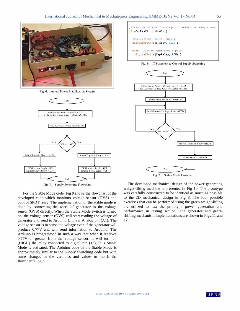
Fig. 6. Actual Power Stabilization System
Fig. 7. Supply Switching Flowchart
For the Stable Mode code, Fig 9 shows the flowchart of the
developed code which monitors voltage sensor (GVS) and
control SPDT relay. The implementation of the stable mode is
done by connecting the wires of generator to the voltage
sensor (GVS) directly. When the Stable Mode switch is turned
on, the voltage sensor (GVS) will start reading the voltage of
generator and send to Arduino Uno via Analog pin (A1). The
voltage sensor is to sense the voltage even if the generator will
produce 0.77V and will send information to Arduino. The
Arduino is programmed in such a way that when it receives
0.77V or greater from the voltage sensor, it will turn on
(HIGH) the relay connected to digital pin (13), thus Stable
Mode is activated. The Arduino code of the Stable Mode is
approximately similar to the Supply Switching code but with
some changes in the variables and values to match the
flowchart’s logic.
Fig. 8. If-Statement to Control Supply Switching
Fig. 9. Stable Mode Flowchart
The developed mechanical design of the power generating
weight-lifting machine is presented in Fig 10. The prototype
was carefully constructed to be identical as much as possible
to the 2D mechanical design in Fig 3. The four possible
exercises that can be performed using the green weight-lifting
are utilized to test the prototype power generation and
performance in testing section. The generator and gears-
shifting mechanism implementations are shown in Figs 11 and
12.

International Journal of Mechanical & Mechatronics Engineering IJMME-IJENS Vol:17 No:04 56
173904-5656-IJMME-IJENS © August 2017 IJENS I J E N S
Fig. 10. Green Weight Lifting Machine Prototype
Fig. 11. Generator Connection
Fig. 12. Gears-Shifting Mechanism Connection
IV. TESTING AND RESULTS
The prototype was tested using five experiments where four
tests are to obtain different parameters: lifted weight in
kilograms, voltage, current and generated power for each
exercise and in six gears. The last test is to compare the
average generated power during different exercises, therefore
finding the highest generation of power among all exercises.
Test 1 (Pull-Down Exercise): The actual experimental
setup of Test 1 is showed in Fig 13 which includes the power
stabilization system, multimeter to display current, and 3
Farads capacitor. The setups of the other experiments are
similar to the Pull-Down test but by using different exercises.
The gear levels were changed six times to obtain several sets
of readings to find the generated power when varying the
gears.
Fig. 13. Actual Experimental Setup of Testing
Table 3 shows the experimental data of test 1 where the
Pull Down exercise was tested two times for each gear level
(six gears). The generated power is calculated using the
obtained voltage and current parameters. Kilograms (lifted
weights) column represents the values that were displayed on
the weight meter during each gear level.
TABLE III OBTAINED DATE DURING PULL-DOWN EXERCISE
Fig 14 shows an analysis between the two tests of Pull-
Down exercise where the generated power of each gear level
in test 1 is compared with the second test, to show how well
and stable is the power generation. In gears 1, 4 and 6 the
generation is approximately stable under both tests, whereas
for gears 2, 3, and 5 there is an average 1.433W difference
between the generation level in test 1 and 2. This can be due to
slight change in the applied force during the testing which
caused imprecision in the readings. It is also noticed from the
analysis that when increasing the gears (higher kilograms) the
generation of power is reduced. This is because the lifting
process is slower, thus lower rotation of the generator, which

International Journal of Mechanical & Mechatronics Engineering IJMME-IJENS Vol:17 No:04 57
173904-5656-IJMME-IJENS © August 2017 IJENS I J E N S
caused a reduction in the generated current therefore
decreased power generation.
Fig. 14. Data Analysis of Pull-Down Exercise
Test 2 (Chest Press Exercise): The collected data during the
testing are listed in Table 4 and analysed in Fig 15.
TABLE 4. OBTAINED DATA DURING CHEST PRESS EXERCISE
Test 3 (Butterfly Exercise): Table 5 and Fig 16.
TABLE V
OBTAINED DATA DURING BUTTERFLY EXERCISE
Fig. 15. Data Analysis of Chest Press Exercise
Fig. 16. Data Analysis of Butterfly Exercise
Test 4 (Legs Exercise): Table VI and Fig 17.
TABLE VI
OBTAINED DATA DURING LEGS EXERCISE
Test 5 (Comparison Test): The average power generation
values of the two trials in each gear level in each exercise are
calculated and listed in Table 7. The column chart in Fig 18
illustrates the average power generation of each exercise under
specific gear level. It is clear that the first gear level has the
highest generation of watts, and the generation decreases as
the gear level is increased.
Pull-Down exercise generates the highest amount of power
when same weight is lifted by other exercises which can be
noticed in Fig 18. This finding is true except when the third
gear is selected, as Chest Press exercise has higher power

International Journal of Mechanical & Mechatronics Engineering IJMME-IJENS Vol:17 No:04 58
173904-5656-IJMME-IJENS © August 2017 IJENS I J E N S
generation of 0.245W when compared to Pull-Down exercise.
Another outcome of this comparison is that the power
production in the different exercises and under fifth and sixth
gear levels is slightly reduced in each exercise.
Fig. 17. Data Analysis of Legs Exercise
TABLE VII
AVERAGE POWER GENERATION FOR EACH EXERCISE
Gear
Level
Pull-
Down
(W)
Chest
Press
(W)
Butterfly
(W)
Legs (W)
1 31.36 30.735 31.01 29.025
2 27.64 27.2 27.37 26.165
3 21.805 22.05 20.795 20.49
4 17.655 17.43 16.54 15.86
5 13.78 13.53 13.41 13.21
6 11.91 11.565 11.335 10.915
Fig. 18. Average Power Generation Comparison
V. DATA INTERPRETATION
Table 8 shows a comparison between the theoretically
calculated kilograms in each gear (Table 2) and the actual
kilograms obtained by the weight meter during the testing.
From the testing tables of each exercise, the average actual
kilograms were calculated. The error column represents the
error level in percentage between the calculated and actual
kilograms. Fig 19 is an analysis between the derived
kilograms by each gear level with the average actual
kilograms obtained during the four exercises testing. The data
are showing high degree of accuracy as the average lifted
kilograms are close to the original values. The highest
similarity level is caused by gear level 5 as the average
obtained kilograms value is less by 0.7495kgs as compared to
the original value (29.5245kgs) with a percentage error of
2.54% only.
TABLE VIII
DATA COMPARISON & PERCENTAGE ERROR
Gear Level Calculated
Kilograms
Actual
Average
Kilograms
Error (%)
1 21.906 21.075 3.79
2 24.0192 23.15 3.62
3 25.8004 25.0125 3.05
4 27.9080 27.00 3.25
5 29.5245 28.775 2.54
6 31.9940 30.825 3.65
Fig. 19. Calculated versus Actual Average Kilograms
VI. CONCLUSION
The aim of modifying the available weight-lifting machine
to be a power generating unit was successfully accomplished
by satisfying the project’s three objectives. The mechanical
design of the green weight-lifting machine was developed by
using high torque generator and suitable gears-shifting
mechanism instead of the original weights of the machine.
Several components were also utilized to construct the
mechanical design such as chains, weight meter, springs,
pulleys, wheel, and L-shape aluminums bars to interconnect
all the mechanical parts. The last objective was achieved by
integrating a power stabilization system which amplifies and
stabilizes the output power of the weight-lifting machine with
the help of 3 Farads capacitor, buck-boost convert, voltage
sensors, relays and Arduino Uno. The testing of the developed
machine showed 96.7% of accuracy when comparing the
attained results to the theoretical findings. The project can be
further improved as follow: reducing the machine’s size by
incorporating built-in generator in the wheel, and introducing
electronic clutch for the gears-shifting mechanism to shift the

International Journal of Mechanical & Mechatronics Engineering IJMME-IJENS Vol:17 No:04 59
173904-5656-IJMME-IJENS © August 2017 IJENS I J E N S
gears freely without jerking therefore decrease the chances of
damaging the gears.
VII. REFERENCES [1] Haji, M., Lau, K. & Agogino, M. (2010) Harnessing Human Power for
Alternative Energy in Fitness Facilities: A Case Study. In Energy Management. 57 (2). p. 326 - 357.
[2] Jahanmahin, M. et al. (2012) Improved configurations for Dc to Dc
buck and boost converters. In IEEE Conference on Power Electronics and Drive Systems Technology. Tehran and 15th – 16th February 2012.
pp. 372-378.
[3] Kayano, S., Sanada, M. & Morimoto, S. (2010) Power Characteristics of a Permanent Magnet Flux Switching Generator for a Low-speed
Wind Turbine. In Power Electronics Conference (IPEC). Sapporo and
21st – 24th June 2010. pp. 258-263. [4] Lee, G. & Jung, T. (2013) Design of Dual Structural Axial Flux
Permanent Magnet Generator for Small Wind Turbine. In TENCON
Spring Conference. Sydney and 17th – 19th April 2013. pp. 90-94.
[5] Neto, J. et al. (2013) DSP Based Fuzzy Controller Applied to a DC-DC
Boost Converter. In IEEE Conference on Intelligent Signal Processing
(WISP). Funchal and 16th – 18th September 2012. pp. 54-59. [6] Pavlovic, T., Bajazic, T. & Ban, Z. (2013) Simplified Averaged Models
of DC–DC Power Converters Suitable for Controller Design and
Microgrid Simulation. In Power Electronics. 28 (7). p. 3266 - 3275. [7] Potgieter, J. & Kamper, J. (2012) Optimum Design and Technology
Evaluation of Slip Permanent Magnet Generators for Wind Energy Applications. In Energy Conversion Congress and Exposition (ECCE)
Conference. Raleigh and 15th – 20th September 2012. pp. 2342 - 2349.
[8] Rajan, J. & Bhagawath, J. (2013) Constant Output Under Transient Condition in Wind Turbine using Novel Boost Converter. In Circuits,
Power and Computing Technologies (ICCPCT) International
Conference. Nagercoil and 20th – 21st March 2012. pp. 381 - 387. [9] Rodriguez, R. et al. (2013) Optimizing the Efficiency of a dc-dc Boost
Converter Over 98% by Using Commercial SiC Transistors with
Switching Frequencies from 100 kHz to 1MHz. In IEEE Conference on Applied Power Electronics Conference and Exposition (APEC). Long
Beach and 17th – 21st March 2013. pp. 641 - 648.
[10] Salazar, P. et al. (2011) Design of a Sliding Mode Control for a DC-to-DC Buck-Boost Converter. In Circuits and Systems. 51 (8). p. 1539 -
1551.
[11] Wannakarn, P. et al. (2011) Design and Construction of Axial Flux Permanent Magnet Generator for Wind Turbine Generated DC Voltage
at Rated Power 1500 W. In IEEE Conference on Electric Utility
Deregulation and Restructuring and Power Technologies. Shandong and 6th – 9st July 2011. pp. 763 - 766.
[12] Wang, L., Yang, Z. & Song, L. (2012) Power Efficiency of Outer-rotor
Permanent Magnet Wind Generator. In Networking, Sensing and Control (ICNSC) IEEE International Conference. Beijing and 11th –
14th April 2012. pp. 222 - 227.
![Help Manual - Shimanoe-tubeproject.shimano.com/pdf/en/HM-EO.3.3.0-00-EN.pdf · * During this operation, ... [OFF] in [Other Shifting Switch]. [Gear-shifting interval] The gear-shifting](https://img.dokumen.tips/doc/110x75/5abdf0ba7f8b9a8e3f8c6455/help-manual-shimanoe-during-this-operation-off-in-other-shifting-switch.jpg)