Embed Size (px)
Citation preview

Green Building Council of Australia Phone: 02 8252 8222 | Fax: 02 8252 8223 | [email protected] | www.gbcaus.orgLevel 4/249 Pitt Street Sydney NSW 2000 | PO Box Q78 QVB NSW 1230
2005 Architecture
Green Star Diffusion
Printed with soya based inks on 100% recycled paper

CONTENTS
CONTENTS.............................................................................................1 The Project and Acknowledgements ..........................................................................................4
SECTION 1 .............................................................................................5 INTRODUCTION.....................................................................................5
The Australian Property Industry and the Environment ..............................................................5 The Green Building Council of Australia and Green Star............................................................5 How this Document relates to Architects ....................................................................................6
Green Star and the Architect ........................................................................................7
THE ROLE OF THE GREEN ARCHITECT ............................................9 Architects in an Integrated Design Team....................................................................................9 About Integrated Building Design ...............................................................................................9 An Integrated Design Process for Office Projects.....................................................................11
Briefing and Concept Design......................................................................................11 Sketch Design, Design Development and Documentation .........................................12 Construction Administration and Commissioning .......................................................14 Case Study – Council House 2 (CH2) ........................................................................14 Other References .......................................................................................................14
SECTION 2 ...........................................................................................16 GREEN BUILDING CONCEPTS AND SYSTEMS ...............................16 [1] DESIGNING FOR CLIMATE .........................................................16
[1.1] Hot Dry Warm And Cold Winter – Arid...........................................................................17 [1.2] Hot And Warm Humid ....................................................................................................17 [1.3] Warm Temperate ...........................................................................................................17 [1.4] Cold ...............................................................................................................................17 [1.5] Design Strategies and Principles ...................................................................................17 [1.6] Using Strategies suitable to the Climate ........................................................................18 [1.7] Office Servicing Strategies and their applicability to Climate Conditions .......................19
[2] OCCUPANT THERMAL COMFORT.............................................21 [2.1] Comfort Zone .................................................................................................................22 [2.2] Adaptive Models ............................................................................................................22
Method of measurement.............................................................................................23 [2.3] Importance of Radiant Systems.....................................................................................23 [2.4] Computer Modelling.......................................................................................................23 [2.5] Designing For Context – Climate, Site & Client..............................................................26
[3] ORIENTATION ..............................................................................27 [4] BUILDING ENVELOPE.................................................................27
[4.1] Building Form.................................................................................................................27 [4.2] Façade Systems ............................................................................................................28 [4.3] Roofs .............................................................................................................................28 [4.4] Computer modelling – Building Envelope ......................................................................29 [4.5] Glazing Units..................................................................................................................29 [4.6] Air Tightness ..................................................................................................................29 [4.7] Green Star – Building Envelope.....................................................................................30
[5] NATURAL VENTILATION, PASSIVE HEATING & COOLING ....31 [5.1] Single Sided...................................................................................................................31 [5.2] Cross Ventilation............................................................................................................33 [5.3] Stack Ventilation ............................................................................................................33

2
[5.4] Checklist for Natural Ventilation .....................................................................................35 Design Considerations ...............................................................................................35 Problems associated with Building Openings.............................................................35 Tropical Environments................................................................................................36 Office Issues...............................................................................................................36 Retail Issues...............................................................................................................37 Equipment Layout ......................................................................................................37
[5.5] Computer Modelling of Natural Ventilation.....................................................................38 [5.6] Natural Ventilation and associated Passive Design Strategies......................................38
Solar Chimneys ..........................................................................................................39 Thermal mass.............................................................................................................40 Shifting peak load.......................................................................................................41 Earth and Geothermal Conditioning ...........................................................................41 Labyrinth.....................................................................................................................41 Night time purge ventilation ........................................................................................42 Night sky radiant cooling ............................................................................................42
[6] MECHANICAL VENTILATION, HEATING & COOLING..............43 [6.1] Considerations for Ventilation ........................................................................................43
Mixed Mode Ventilation (Natural & Mechanical).........................................................43 Computer Modelling – Mechanical Ventilation............................................................44
[6.2] Dehumidification ............................................................................................................44 [6.3] Heat Exchangers ...........................................................................................................45 [6.4] System Design...............................................................................................................45
Leaks..........................................................................................................................45 Insulation ....................................................................................................................45 Zoning ........................................................................................................................45
[6.5] Low Pressure Systems ..................................................................................................46 Larger Ducts...............................................................................................................46 Circular Ducts.............................................................................................................46 Reduce Bends for Efficiency ......................................................................................46 Efficient Diffusers .......................................................................................................46
[6.6] Displacement Ventilation (UAD).....................................................................................46 Benefit of Radiant Systems ........................................................................................48 Cooling Systems ........................................................................................................48 Chilled Technologies ..................................................................................................50 Storage Systems ........................................................................................................52
[7] NATURAL AND ARTIFICIAL LIGHTING .....................................53 [7.1] Views .............................................................................................................................53 [7.2] Daylighting Strategies ....................................................................................................54
Limitation of Daylighting Strategies ............................................................................55 [7.3] Daylight Glare Control....................................................................................................56 [7.4] Computer Modelling.......................................................................................................56 [7.5] Artificial Lighting.............................................................................................................58
GREEN STAR – OFFICE DESIGN CREDITS AND THE ARCHITECT 59 GREEN STAR – OFFICE DESIGN ARCHITECTS’ GUIDE .................61
MANAGEMENT........................................................................................................................61 Man – 1 ‘Green Star Accredited Professional’ .......................................................61 Man – 7 ‘Waste Management’ ................................................................................61
INDOOR ENVIRONMENT QUALITY........................................................................................62 IEQ – 1 ‘Ventilation Rates’.....................................................................................62 IEQ – 2 ‘Air Change Effectiveness’........................................................................63

3
IEQ – 4 ‘Daylighting’ ..............................................................................................63 IEQ – 5 ‘Daylight Glare Control’.............................................................................64 IEQ – 8 ‘External Views’ ........................................................................................65 IEQ – 12 ‘Internal Noise Levels’ ............................................................................66 IEQ – 13 ‘Volatile Organic Compounds’ ................................................................66 IEQ – 14 ‘Formaldehyde Minimisation’ ...................................................................66 IEQ – 16 ‘Tenant Exhaust Riser’ ...........................................................................67
ENERGY ..................................................................................................................................67 Ene – 1 ‘Energy’ ....................................................................................................67 Ene – 2 ‘Energy Improvement’ ..............................................................................69
TRANSPORT ...........................................................................................................................69 Tra – 1 ‘Provision of Car Parking’ ..........................................................................69 Tra – 2 ‘Small Car Spaces’ ....................................................................................70 Tra – 3 ‘Cycling Facilities’ ......................................................................................70
WATER.....................................................................................................................................71 Wat – 1 ‘Occupant Amenity Potable Water Efficiency’...........................................71
MATERIALS .............................................................................................................................72 Mat – 1 ‘Recycling Waste Storage’ ........................................................................72 Mat – 2 ‘Reuse of Façade’.....................................................................................72 Mat – 3 ‘Reuse of Structure’ ..................................................................................72 Mat – 4 ‘Shell and Core or Integrated Fit-out’ ........................................................73 Mat – 5 ‘Recycled Content of Structural Concrete’ ................................................73 Mat– 6 ‘Recycled Content of Structural Steel’ .......................................................74 Mat – 7 ‘PVC Minimisation’....................................................................................74 Mat – 8 ‘Sustainable Timber Selection’..................................................................75
LAND USE AND ECOLOGY ....................................................................................................75 Eco – 1 ‘Ecological Value of the Site’ ....................................................................75 Eco – 4 ‘Change of Ecological Value’ ....................................................................75
EMISSIONS..............................................................................................................................76 Emi – 7 ‘Light Pollution ..........................................................................................76 Emi – 9 ‘Insulant Ozone Depleting Potential’.........................................................76
INNOVATION ...........................................................................................................................76 Inn – 1 ‘Innovative Strategies And Technologies’ ...................................................77 Inn – 2 ‘Exceeding Green Star Benchmarks’ ..........................................................77 Inn – 3 ‘Environmental Design Initiatives’ ..............................................................77

4
The Project and Acknowledgements In April 2004, the Green Building Council of Australia (GBCA) and its project partners, the Royal Australian Institute of Architects (RAIA), the Australian Institute of Refrigeration Air Conditioning & Heating (AIRAH) and the Property Council of Australia (PCA) were successful in attracting Department if Industry, Tourism and Resources – AusIndustry Innovation Access Program funding assistance for a project to develop professional development materials to support architects and mechanical engineers in the uptake of Green Star innovation and for the property industry. This project entitled ‘Green Star Diffusion - Architecture’ aims to ensure that the innovation contained in the Green Star – Office Design rating tool is made available to architects to support them in the attainment of green building capabilities. An important component of the Green Star Diffusion project was to attempt to understand how professional services practices were engaging with innovation and how practitioners preferred to learn and continue to develop their practice capabilities. An early component of the project included a series of workshops, conducted by Huston Eubank of the USA Rocky Mountain Institute, to provide knowledge and insights about these issues which could be used to guide the Implementation Manual content writers. The outputs of this component proved invaluable. To provide continuing advice to the content writers on matters of relevance and appropriateness of material, RAIA convened a reference group of practitioners comprising architects and designers from a range of practices, large and small. This reference group included practitioners with green building experience and those without, who saw this document in its evolution and provided invaluable guidance. Finally, the material gathered was compiled into its present form through the assistance of Betty Tseng of Mirvac who provided advice and contributed greatly to the final development strategies and writing. ‘Green Star Diffusion – Architecture’ is a work in progress and is designed to grow in line with the increasing sophistication and reach of the Green Star environmental rating tools. Acknowledgements The project team wishes to thank all those who have given support, encouragement and advice to the project: in particular, Catherine Evans – Royal Australian Institute of Architects, Huston Eubank – USA Rocky Mountain Institute, Dominique Hes – RMIT University, Asif Din – RMIT University, Clare Newton – University of Melbourne, Graham Crist – RMIT University, Alex Nock – Woodhead International, David Oppenheim – Sustainable Built Environments, Natasha Palich – City of Port Phillip, Andrew Walker Morison – RMIT University, Betty Tseng - Mirvac, Mark Thomson – TVS Partnership and Louise Walker – Green Building Council Australia. The GBCA gratefully acknowledges the support of the Commonwealth Department of Industry, Tourism and Resources through the AusIndustry Innovation Access Program. Richard Sebo Green Star Diffusion Project Manager

5
SECTION 1
INTRODUCTION
The Australian Property Industry and the Environment Buildings have a significant impact on the environment, consuming 32% of the world's resources including 12% of its water. Buildings also produce 40% of waste going to landfill and 40% of air emissions. In Australia, commercial buildings produce 8.8% of the national greenhouse emissions, and have a major part to play in meeting Australia's international greenhouse obligations. A commercial building sector baseline study found that office buildings and hospitals were the two largest emitters by building type, causing around 40% of total sectoral emissions1. The property industry is well placed to deliver significant long-term environmental improvements using a broad range of measures. The breadth of the industry and its depth in terms of the supply chain are far-reaching in its impact on the environment. Similarly, green practices and systems in this industry can also deliver significant improvement on the overall impact on the environment. Improvements can include behavioural changes at all stages of the supply chain resulting in green practices and systems.
The Green Building Council of Australia and Green Star The objective of the GBCA is to drive the transition of the property industry towards sustainability. A key priority for the GBCA has been the development of a comprehensive environmental rating system for buildings, known as ‘Green Star’. A Green Star tool evaluates separately the environmental initiatives of designs, projects and/or buildings based on a number of criteria, including energy and water efficiency, indoor environment quality and resource conservation. Green Star aims to:
♦ Establish a common language and standard of measurement for green buildings;
♦ Promote integrated, whole-building design; ♦ Identify building life-cycle impacts; ♦ Raise awareness of green building benefits; ♦ Recognise environmental leadership; and ♦ Minimise the environmental impact of development and improve the built
environment. Green Star will have rating tools for different phases of the building life-cycle (design, fit-out and operation) and for different building classes (office, retail, health, education, residential, industrial etc). Green Star - Office Design was the first Green Star rating tool released. 1 Environmentally Sustainable Buildings: Challenges and Policies’ – a report by the OECD, 2003; ‘Australia State of the Environment 2001’ – a report by the Australian State of the Environment Committee for the Commonwealth Minister for the Environment and Heritage, 2001

6
Green Star has been developed based on existing systems and tools in overseas markets, including the British BREEAM (Building Research Establishment Environmental Assessment Method) system and the North American LEED (Leadership in Energy and Environmental Design) system, by establishing individual environmental measurement criteria relevant to the Australian marketplace and environmental context. Green Star rating tools refer to regulatory standards to encourage the property industry to ameliorate the impact of development on the environment. The rating tools embrace local standards and guidelines where applicable to benchmark this improvement. The GBCA has developed Green Star to provide industry with an objective measurement for assessing green buildings. In order to facilitate rating and promote change towards green practices, the GBCA has been diligent in focusing on those areas of environmental impact that are a direct consequence of a building’s briefing, design, construction and maintenance - that is, those outcomes that can be directly influenced by stakeholders within the property industry. Green Star establishes a number of categories under which specific key criteria are grouped and assessed. This framework is used by each and every Green Star rating tool. The basic Green Star structure is shown below.
• Management
• Indoor Environment Quality
• Energy
• Transport
• Water
• Materials
• Land Use and Ecology
• Emissions
• Management
• Indoor Environment Quality
• Energy
• Transport
• Water
• Materials
• Land Use and Ecology
• Emissions
Ass
essm
ent C
redi
ts
Issu
e C
ateg
ory
Scor
es
Envi
ronm
enta
l Wei
ghtin
gs
Sing
le S
core
Rating
• Innovation
Figure 1 - Structure of the Green Star rating system
How this Document relates to Architects
This document is specifically designed for architects and building design professionals in the building industry. Its aim is to forward an understanding of green building concepts amongst designers and to identify opportunities for the implementation of green initiatives. To do this, the document looks at: • The role of the architects in particular in the design, development,
construction and commissioning of a commercial office building; • How Green Star - Office Design overlaps with the typical role of the architect
and where that architect’s input can influence a Green Star - Office Design rating for a new or refurbished Class 5 building;

7
This document’s primary aim is to diffuse the innovation promoted by Green Star – Office Design and encourage holistic integration of these principles in typical office projects to achieve improved environmentally sustainable outcomes that are capable of delivering immediate benefit to building occupiers and improve productivity and long-term business operating costs. This document is not intended to be: • A design guide or represent definitive design advice; • A guaranteed method of obtaining a Green Star Office Design Certified
Rating; • An alternative or substitute for any Green Star Technical Manual.
Green Star and the Architect The Green Star Diffusion Project for Architects seeks to address the key design and construction issues for architects covered by Green Star Office Design. Many aspects of Green Star Office Design require the architect to develop and implement the project and design brief with knowledge of available building systems, technologies and materials that are more environmentally sustainable. The use of Green Star - Office Design can be seen as adding, expanding and/or making transparent green initiatives, which in most instances are intrinsic to the practice of good building design. Figure 2 provides an overview of the anticipated scope of involvement required of the architect and other consultants on a project team. The intention of Figure 2 is to illustrate in general where the key consultants would need to work together to arrive at a desirable outcome, particularly in terms of brief setting and design development, under each Green Star – Office Design criterion. It is not intended to be an exhaustive summary or list of skills required for a project as each project’s scope and design requirements differ from one another.

8
Figure 2 – Design Consultants

9
THE ROLE OF THE GREEN ARCHITECT
Architects in an Integrated Design Team The architect would typically have an integrative role from inception to completion of a typical office project. The way that such a role is carried out in an integrated design process can have a big impact on the success of design outcomes, and the ability of the project to deliver innovative and sustainable designs. Integrated design is a process that delivers value by understanding impacts across a broad range of disciplines during design and subsequently by physically integrating the initiatives and building components to achieve superior outcomes2. This section looks at integrated building design and how the architect’s role is instrumental in an integrated design process to achieve improved outcomes.
About Integrated Building Design3 Integrated building design is a process of design in which multiple disciplines and seemingly unrelated aspects of design are integrated in a manner that permits synergistic benefits to be realised. The goal is to achieve high performance and multiple benefits at a lower cost than the total for all the components combined. This process often includes integrating green design strategies into conventional design criteria for building form, function, performance, and cost.
A key to successful integrated building design is the participation of people from different specialties of design: general architecture, HVAC, lighting and electrical, interior design, and landscape design. By working together at key points in the design
2 Wall, Ché (2000), DES 36 “An Approach for Integrated Systems Design”, BDP Environment Design Guide, RAIA. 3 Text adapted from DOE website - http://www.eere.energy.gov/buildings/info/design/integratedbuilding/ last accessed 21/12/2004

10
process (particularly at the earliest conceptual stages), these participants can often identify highly attractive solutions to design needs that would otherwise not be found. In an integrated design approach, the architect’s conceptual design for the base building would be discussed and modelled, albeit crudely to begin with, by other consultants on the project team, such as by the mechanical and electrical engineers to estimate HVAC and energy-use implications of the design. An integrated design approach is by nature often iterative and would require extensive information coordination, assimilation, evaluation and implementation. The architect’s design development process of the architecture would be rigorously driven and challenged progressively by this collective approach.
Figure 9 – Integrated design reflects interrelated nature of a building http://www.esru.strath.ac.uk/Courseware/Class-16293/19-Integrated.pdf Last
Accessed 19/01/2005
In today’s design and construction environment, an integrated design approach is increasingly the norm. An example of an excellent integrated design outcome in a commercial building involving mechanical engineers and architects could be the consideration of chilled beams against a typical VAV system. In a traditional, non-integrated design approach, the mechanical engineer could overlook or discount a chilled beam option if the mechanical system costs were higher. In an integrated approach, the architectural savings of an increased floor-to-floor height, or the opportunity to increase Net Lettable Area (NLA) from an additional floor, would be considered against the increased mechanical costs, thereby opening up more green design opportunities without increasing cost.
The integration of building design strategies is worth considering for all aspects of green design: improving energy efficiency, planning a sustainable site, safeguarding water, creating healthy indoor environments, and using environmentally preferable materials. Where all members of the design team – from civil engineers to interior designers – have common goals that were set in the building program, and which were set with their buy-in, it becomes easier to see innovative design concepts through past the schematic design stage.
Building Form and Function

11
One of the best ways to drive an integrated design approach is to stress a team-building approach in the procurement of architectural and engineering services, with provisions for integrated design incorporated into the scope during the concept design phase. An example would be a scope which included frequent meetings and a significant level of input from mechanical engineers at the concept design stage to evaluate and have buy-in for various green initiatives.
An Integrated Design Process for Office Projects An office environment is a communal work setting for a group of people that accommodates and facilitates the carrying out of the work required. It is therefore important to maintain a consistently healthy and productive environment. However, as the outdoor natural environment changes from dawn to dusk and from season to season, the internal built environment would also change. The office built form and building services depending on the skill of the architect and engineers can either ameliorate or intensify the impact that changing natural environment would have on the internal environment. Therefore, building design and services are significant in determining the extent of artificial systems and control required to maintain the desirable environmental outcome. In order to maintain appropriate internal environmental conditions, environmental measures and controls need to be established and monitored.
Design by nature is a not a linear process. However, many aspects of design such as functionality assessment including form, spatial and services design can be approached methodically. Being a member of an integrated design process, it is imperative for the architect to be acutely aware of commercial impacts and be able to demonstrate financial benefits. In doing so, the architect is facilitating the client’s acceptance of green building design as accepted practice and as a value-adding aspect of a project instead of a social cost burden. One of the most challenging aspects of contemporary architectural project delivery is coordination and integration of various consultant and expert input. Quite often it is the coordination and integration within a project team that determines the success of a project and hence the increasing emphasis on an integrated design process.
As a guideline, the typical architecture design process in the context of an integrated design process is described below to illustrate the importance of the architect’s involvement.
Briefing and Concept Design During the predesign stage before the architect commences with building design, the first step for any type of project should always be the setting of a project brief. The complexity of a project brief largely depends on the nature of the project, the stakeholders and the project team involved. Green building design increasingly has become a central element of a project brief due to the number of building design and services aspects it has influence on (directly or indirectly). The project brief once established also sets the initial context and parameters that all aspects of the project must relate to. It is often necessary to have briefing workshops to establish a project brief. The list of participants would gradually lengthen as the predesign stage advances to include

12
the client, the architect, consultants including at least the engineers, the quantity surveyor and the project manager if there is one, and preferably also the building contractor from as early on as practicable. In simplest terms, the brief is ultimately the client’s commitment towards the level of quality of the project to be achieved (which in addition to the built form may also include community consultation and other urban outcomes), the budget available, and the project team assembled including the client. Concurrent to the briefing process is the Concept Design process. Concept design and the project brief go hand in hand so that the resultant brief is practical and the concept design progresses acknowledging the constraints and can therefore be more effective in the search for alternative solutions and innovative ideas. Some of the key architectural aspects important to the setting of the brief and to progressing the concept design include:
Informing the client on the potential of green building opportunities and the broader benefits of taking such actions;
Designing for the macro-climate, and for the microclimate and orientation of the site;
Specification to be based on needs analysis to avoid under- or over-specification;
Adopting an inter-disciplinary integrated approach to design including early identification of consultants required and selection of consultants with appropriate green building credentials including a Green Star Accredited Professional.
Sketch Design, Design Development and Documentation The design and analysis process for developing integrated building designs includes:
♦ Establishing a base case—for example, a performance profile showing energy use and costs for a typical facility that complies with code and other measures for the project type, location, size, etc.
♦ Identifying a range of solutions—all those that appear to have potential for the specific project.
♦ Evaluating the performance of individual strategies—one by one through sensitivity analysis or a process of elimination parametrics
♦ Grouping strategies that are high performers into different combinations to evaluate performance.
♦ Selecting strategies, refining the design, and reiterating the analysis throughout the process.
Finding the right building design initiatives through an integrated design process can be challenging. At first, design teams often make incremental changes that are effective and result in high-performance buildings—and often at affordable costs. However, continuing to explore design integration opportunities can sometimes yield incredible results, in which the design team breaks through the cost barrier. The building design begins with an analysis of the required spaces. With an eye toward the green building targets established in pre-design, the individual spaces should be clearly described in terms of their function, occupancy and use, daylight and electric light requirements, indoor environmental quality standards, acoustic isolation needs, and so on. Spaces then can be clustered by similar function, common thermal zoning, need for daylight or connection to outdoors, need for privacy or security, or other relevant criteria.

13
Whenever one green strategy can provide more than one benefit, there is a potential for design integration. For example, windows can be highly cost-effective even when they are designed and placed to provide the multiple benefits of daylight, passive solar heating, summer-heat-gain avoidance, natural ventilation, and an attractive view. A central corridor, common in historic buildings, provides daylight and natural ventilation to each room, and transom windows above doors provide lower levels of light and ventilation to corridors. Building envelope and lighting design strategies that significantly reduce HVAC system requirements can have remarkable results. Sometimes the most effective solutions also have the lowest construction costs, especially when they are part of an integrated design. The built form is the primary mechanism for reducing energy loads. A proactive approach is for the energy efficiency aspects to set the constraints against which the building components can be developed. Such constraints may include the building plan depth, the proportion of glazed façade, solar shading requirements and thermal massing. Services design should be informed by the ability of the building to modify the climate and reduce energy consumption. A range of environmental design tools such as building thermal modelling, daylighting assessment, indoor environment quality assessment, and plant and systems modelling, may need to be employed and commence assessment during the sketch design stage to evaluate and guide the building and services design. This is the core of the integrated design process and requires extensive communication, coordination and integration of assessment outcomes and adjustment required amongst the architect, services engineers and various consultants. It is often during conceptual design that existing accepted practices are challenged as part of the design process in search of the most suitable system for a building. This further intensifies the inter-disciplinary coordination required to fully understand the practicality and financial feasibility of a proposed system. The assessment outcome, especially the cost-and-benefit analysis, needs to be presented to the client for informed decision-making. The use of the chilled beam option described previously would reduce the amount of air required to pass through a building can reduce floor-to-floor heights and thereby increase the yield on a high-rise office development and reducing the fit-out cost per square metre of NLA, even though the capital cost of a chilling ceiling is higher than a VAV system. Various observations of recent industry practices suggest that the integrated design process can protract the concept design stage and further blur the distinction between concept design and detailed design. This has seen building professionals gradually re-formulating their fee structures. In principle, especially for projects that require submissions to the local governing authorities for development permits or approvals, the Sketch Design stage rolls into Detailed Design when the building design and services systems have been sufficiently decided on for application documentation to be finalised. As design development progresses with the building and services design taking shape, so does architectural documentation including specifications. Part of the design development process would include material selection for construction materials, interior and exterior finishes. There are increasingly more green materials available in the marketplace. There are also opportunities for further examination of the construction practices and processes to minimise the use of new materials. This may involve investigating alternative

14
construction technologies, introducing or increasing the recycled content of building materials such as recycled concrete, timber and steel.
Construction Administration and Commissioning Depending on whether the architect is involved in the tender assessment and undertakes full contract administration, the architect’s role in these areas would range from advisory only to that of a contract administrator or a client representative. Whilst it is the building contractor’s responsibility to ensure that the building is constructed in accordance with the architectural and various engineering design and specifications, the architect may be required to observe or inspect whether the building is constructed in accordance with the architectural design and specification and provide advice or site instructions depending on the architect’s contractual agreement with the client. The architect may be involved in the preparation of documentation such as the design intent and specifications, and the Building Users’ Guide, in conjunction with other consultants and the contractor in the project team.
Case Study – Council House 2 (CH2) The design approach adopted for the City of Melbourne’s 6 Star Green Star – Office Design building Council House 2 (CH2) is an excellent example of integrated design. One of the unique aspects of the CH2 project was that the City of Melbourne employed the prospective consultants on hourly rates for the concept and workshop process prior to formal engagement. Not only did this give all consultants the opportunity to fully explore and discuss green building initiatives at this stage, it engaged all team members early, allowing them to encourage or discourage initiatives as they saw fit. This was important, because subsequent to formal engagement, team members would not be able to hinder initiatives just because they were no longer enthusiastic about designing them. The result was a 6 Star Green Star - Office Design Certified Rating, which integrated a vast range of innovative and unusual design features, from phase change materials to black water reuse of the sewer.
Other References BDP Environment Design Guide (EDG) published by the Royal Australian Institute of Architects – the following articles from the EDG are good starting points.
GEN 1 “RAIA Environment Policy”, February 1995 & August 2001 GEN 63 “Green Star – A User’s Perspective” by Peter James, November
2004. DES 36 “An Approach for Integrate Systems Design” by Ché Wall,
August 2000. DES 62 “Integrated Design Process Incorporating Lighting” by Mark B
Luther, August 2004.

15
DES 65 “Designing Buildings That Actually Perform” by Dr Paul Bannister, November 2004.
CAS 36 “The Integrated Design Process of CH2” by Stephen Webb, February 2005.
16
SECTION 2
GREEN BUILDING CONCEPTS AND SYSTEMS This section explains the concepts of:
[1] Designing for Climate [2] Occupant Comfort [3] Orientation [4] Building Envelope [5] Natural Ventilation, Passive Heating & Cooling [6] Mechanical Ventilation, Heating and Cooling [7] Natural and Artificial Lighting
.
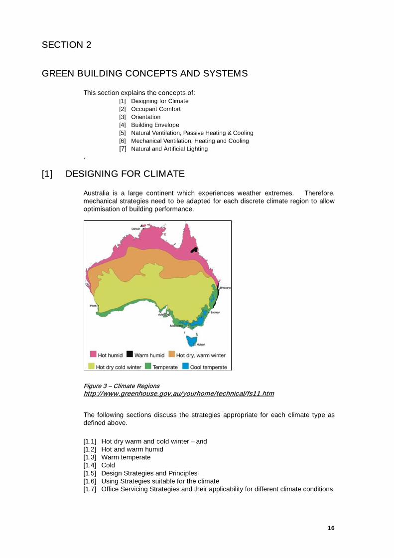
[1] DESIGNING FOR CLIMATE Australia is a large continent which experiences weather extremes. Therefore, mechanical strategies need to be adapted for each discrete climate region to allow optimisation of building performance.
Figure 3 – Climate Regions http://www.greenhouse.gov.au/yourhome/technical/fs11.htm
The following sections discuss the strategies appropriate for each climate type as defined above.
[1.1] Hot dry warm and cold winter – arid [1.2] Hot and warm humid [1.3] Warm temperate [1.4] Cold [1.5] Design Strategies and Principles [1.6] Using Strategies suitable for the climate [1.7] Office Servicing Strategies and their applicability for different climate conditions

17
In many design situations, boundaries and constraints limit the application of cutting edge actions. The design strategies and principles outlined in Section [1.5] should be considered and the basic and passive ones incorporated as much as possible.
[1.1] Hot Dry Warm And Cold Winter – Arid Main characteristics:
♦ Low humidity year round. ♦ High diurnal (day/night) temperature range. ♦ At least two (usually four) distinct seasons. ♦ Low rainfall. ♦ Very hot summers are common. ♦ Cold winters. ♦ Hot, dry winds in summer. ♦ Cool to cold dry winds in winter.
[1.2] Hot And Warm Humid Main characteristics:
♦ High humidity with a degree of or definitive "dry season". ♦ High temperatures year round or mild winter. ♦ Minimum seasonal temperature variation. ♦ Low to moderate diurnal (day/night) temperature range.
[1.3] Warm Temperate
Main characteristics:
♦ Low diurnal (day/night) temperature range near coast to high diurnal range inland.
♦ Four distinct seasons. ♦ Summer and winter can exceed human comfort range. ♦ Spring and autumn are ideal for human comfort. ♦ Mild to cool winters with low humidity. ♦ Hot to very hot summers with moderate humidity.
[1.4] Cold
Main characteristics:
♦ Low humidity. ♦ High diurnal range. ♦ Four distinct seasons. ♦ Winter and Summer exceeds human comfort range. ♦ Cold to very cold winters with majority of rainfall. ♦ Hot dry summers. ♦ Variable spring and autumn conditions.
[1.5] Design Strategies and Principles
♦ Commence strategies to improve energy efficiency at the very beginning of the design process.

18
♦ The entire building should be regarded as a system in which passive and active features interact.
♦ Maximise passive solar design suited to hot arid locations and appreciate the tropics as a unique climatic zone requiring unique design solutions.
♦ Provide a broader range of other passive comfort design elements where passive and low energy cooling contributes substantially to comfort.
♦ Consider intrinsic building comfort performance inherent in the building form, irrespective of energy and systems availability.
♦ Create passive heat extraction from building interiors, generated by thermal courtyard, clerestory and greenhouse building design elements.
♦ Create passive cooling introduced into buildings by shaded courtyard and subsidence tower design elements integral to the building.
♦ Design elements are integral to the building form to create comfort outcomes rather than through attached mechanical solutions.
♦ Integrate active and passive systems to recapture control of the processes. ♦ The achieved comfort contribution is through design elements integral to
building superstructure cost centres, which can offset both traditional services capital and recurrent operating cost allocations in project budgets.
♦ Design elements have the potential to create a regional design for buildings featuring sun-side and shade-side design elements noted above in contrast to traditional symmetry derived building form.
♦ Design elements can interact with related design elements; notably safari roof for increased solar insulation from the building interior, humidification and shading associated with understorey and canopy vegetation, wetting with sprays, fountains, drippers, flow forms for air infeed to the design elements discussed in the original paper. (Prelgauskas, 2003, BDP EDG, DES 20)
♦ Invest in improving understanding of technology and building science. ♦ Understand the application of whole of life impact and cost concepts. ♦ Understand life cycle costs and financial parameters which affect investment in
energy efficiency.
[1.6] Using Strategies suitable to the Climate The chart below shows the technologies which are most effective given temperature and humidity. Passive solar heating is effective if the Dry Bulb Temperature (DBT) is between 15 and 22 and the air has an Absolute Humidity (AH) between 5 and 12 (i.e. cold and relatively dry).
Figure 4 – Effectiveness of Passive Techniques. Image by Dr Andrew Marsh of Square One Research Pty Ltd www.squ1.com (http://www.squ1.com/climate/climate-passive.html)

19
[1.7] Office Servicing Strategies and their applicability to Climate Conditions
Temperate Cold Temperate Hot Humid Warm Humid Dry Warm Winter Dry Cold Winter
Natural Ventilation
Yes Yes, but need to have a heating strategy.
Prior to refrigerant cooling people used natural strategies; it is more difficult to meet current comfort requirements in this climate.
Prior to refrigerant cooling people used natural strategies; it is more difficult to meet current comfort requirements in this climate.
Yes Yes
Chilled Ceiling Panels
Yes4 Yes, though it may not be necessary4.
Not appropriate without humidity control4.
Not appropriate without humidity control4.
May be appropriate if load does not exceed 80w/m2 4.
May be appropriate if load does not exceed 80w/m2 4.
Underfloor Ventilation
Yes Yes Yes Yes Yes Yes
Displacement Ventilation
Yes Yes Yes Yes Yes Yes
Shower Towers
Yes, though it may not be necessary.
Less appropriate. No – too humid therefore not enough evaporation to be effective
No, there would not be enough evaporation to be effective given the humidity.
Yes Yes
Night Cooling
Yes, particularly if there is a medium to large difference between day and night temperatures5.
Yes, particularly if there is a medium to large difference between day and night temperatures5.
Less appropriate5. Less appropriate5. Less appropriate5. Yes, particularly if there is a medium to large difference between day and night temperatures5.
Ice Store Or Night Water Cooling
Ice storage is applicable wherever there is cheaper night electricity available. This does not save energy just stores it when it is cheaper.
Ice storage is applicable wherever there is cheaper night electricity available. This does not save energy just stores it when it is cheaper.
Ice storage is applicable wherever there is cheaper night electricity available. This does not save energy just stores it when it is cheaper.
Ice storage is applicable wherever there is cheaper night electricity available. This does not save energy just stores it when it is cheaper.
Ice storage is applicable wherever there is cheaper night electricity available. This does not save energy just stores it when it is cheaper.
Ice storage is applicable wherever there is cheaper night electricity available. This does not save energy just stores it when it is cheaper.
Direct Evaporative Cooling
Yes, if relative humidity is low. Yes, though it may not be necessary.
No – too humid therefore not enough evaporation to be effective.
No, there would not be enough evaporation to be effective given the humidity.
Yes Yes
4 humidly control necessary for all of these. Note, the higher the humidity the lower the comparative dehumidifying load for chilled ceilings. This is because with chilled beams only the occupancy fresh air requirements are required to be dehumidified. Also note that chilled ceilings can prove
heating to at least 1.5 x their cooling capacity – so good for cold winter areas too).
5 Only applicable is there is exposed thermal mass in the building)

20
Temperate Cold Temperate Hot Humid Warm Humid Dry Warm Winter Dry Cold Winter
Indirect Evaporative Cooling
Yes Yes Yes Yes Yes Yes
Hollow Core Panels
Yes Yes, but need to have a heating strategy.
Less appropriate. Not appropriate. Not appropriate. Not appropriate.
Thermal Mass
Yes, particularly if there is a medium to large difference between day and night temperatures6.
Yes particularly if there is a medium to large difference between day and night temperatures6.
Less appropriate6. Less appropriate6. Yes, if the thermal mass is extremely large underground 6.
Yes, particularly if there is a medium to large difference between day and night temperatures6.
Thermal Chimneys
Yes, if chimneys are correctly sized and there are appropriate climatic conditions.
Yes, if chimneys are correctly sized and there are appropriate climatic conditions
Less appropriate. Less appropriate. Yes, if chimneys are correctly sized and there are appropriate climatic conditions.
Yes, if chimneys are correctly sized and there are appropriate climatic conditions.
Vertical Ducting
Yes, if chimneys are correctly sized and there are appropriate climatic conditions.
Yes, if chimneys are correctly sized and there are appropriate climatic conditions
Less appropriate. Less appropriate. Yes, if chimneys are correctly sized and there are appropriate climatic conditions.
Yes, if chimneys are correctly sized and there are appropriate climatic conditions.
Trombe Walls Yes, for residential. Yes, for residential No No No Yes, for residential.
Double Skin Envelope
Yes, particularly if completely mechanically ventilated, though there is some uncertainty about this technique’s effectiveness.
Yes, particularly if completely mechanically ventilated, though there is some uncertainty about this technique’s effectiveness.
Yes, particularly if completely mechanically ventilated, thought there is still some uncertainty about this technique’s effectiveness.
Yes, particularly if completely mechanically ventilated, though there is some uncertainty about this technique’s effectiveness.
Yes, particularly if completely mechanically ventilated, thought there is still some uncertainty about this technique’s effectiveness.
Yes, particularly if completely mechanically ventilated, though there is still some uncertainty about this techniques effectiveness.
Labyrinths (For Cooling)
Yes Yes, but need to have a heating strategy.
Yes Yes Potentially Yes, but need to have a heating strategy.
6 For offices this is not always appropriate.

21
[2] OCCUPANT THERMAL COMFORT Thermal comfort relates to the building occupant’s experience and reaction to the indoor environment. Occupant thermal comfort is not only about the actual air temperature of a space but also air movement, humidity, radiant temperature etc. The success or failure of a building is often measured by how comfortable the people feel in the building. Research indicates there is variation from person to person and even the same person on differing days. There are however a range of attributes that can be incorporated in the design to facilitate occupant comfort. The climate conditions and the comfort zone for that location must be established. The amount of days that require conditioning such as heating, cooling, humidification or dehumidification should to be established. This section deals only with occupant thermal comfort and does not address other important factors such as indoor air quality, glare, noise etc.:
[2.1] Comfort zone [2.2] Adaptive models
Method of measurement Predicted mean vote (PMV) Percentage of People Dissatisfied (PPD)
[2.3] Importance of radiant systems [2.4] Computer modelling (IEQ 11)
[2.5] Designing for Context – Climate, Site and Client In designing the indoor thermal environment the occupant satisfaction is the first thing that has to be considered. A climate analysis will determine what proportion of the year some conditioning to the external environment is required. Data can be obtained from weather stations to analyse when modifications need to occur. Typical year data should be used warily as this may not take into account extremes experienced on a year to year basis. Other considerations such as microclimate in which the building is located should be identified in modifying open field weather station data7.
The tool below shows the interaction of many of the factors that affect comfort:
Figure 5 - Interactive tool for giving an idea of comfort. Produced by Dr Andrew Marsh of Square One Research Pty Ltd www.squ1.com (http://www.squ1.com/comfort/prediction.html)
7 Weather data is available from the Bureau of Meteorology http://www.bom.gov.au/silo/

22
These conditioning techniques usually have the effect of raising air temperature (heating), lowering air temperature (cooling) and adjustment of the moisture content of the air (humidification / dehumidification).
Figure 6 - Psychometric chart (http://boris.uce.ac.uk/resources/LJ/ba203-condensation.pdf)
[2.1] Comfort Zone
There are numerous factors that are involved in making people feel comfortable. Consider the following:
♦ Solar radiation can help keep building occupants warm even when the air temperature around them is considerably lower. Seasonal variation is taken up in part by the way people dress. In winter people tend to wear more clothes.
♦ If building occupants are able to control their environment by opening
windows, switching on heaters and lights, occupants are more tolerant of their thermal environment. The use of thermostatic valves on radiators could help occupants keep control of their local thermal environment.
♦ Radiant systems should be considered as well as the usual convective
systems as they provide a more even distribution of heat/coolth that is more perceptible to the occupants than conductive or convective systems.
There are other examples including air movement for perceived cooling but common sense must be used in the designing of systems. It is important to understand that the comfort zone is a range of conditions rather than a specific design temperature.
[2.2] Adaptive Models Building occupants are more tolerant of their thermal environment if they are able to control their environment by opening windows, switching on heaters, layering clothes on or off and changing activity rates. This is called the adaptive model of thermal comfort. Adaptive models are based on large sample of experimental data over a range of thermal environments.

23
Method of measurement As this is a qualitative field, a great deal of research has been done. It is made up of the Predicted Mean Vote and the Percentage of People Dissatisfied.
Predicted Mean Vote (PMV) The most successful measure comes from the work of Fanger who established the adaptive model for thermal comfort. This model uses predicted mean vote (PMV) a scale of +3 to -3, too hot to too cold, on how a person would feel in a certain space. From this the percentage of people dissatisfied (PPD) can be calculated the lower the value the better. This has a minimum value of 5% as factors such as age, physical condition and diet has an associated mathematical uncertainty connected to it and mathematical models established.
Percentage of People Dissatisfied (PPD) From PMV, the percentage of people dissatisfied (PPD) can be calculated. As the PMV moves away from 0, the PPD increases. The lower the value the better but PPD figure never falls below 5%. ISO 7730 (1984) uses PMV to determine thermal comfort. The comfort levels have a 5% error rating as a certain amount of factors including age, physical condition, diet and internal body rhythm effect the thermal comfort of an occupant but cannot be easily translated into a mathematical physical equation.
[2.3] Importance of Radiant Systems Radiant systems should be considered as well as the usual convective systems as they provide a more even distribution of heating/cooling that is more perceptible to the occupants. Radiant heating and cooling is more effective than other heating on occupant thermal comfort.
[2.4] Computer Modelling From a range of factors, the thermal environment can be modelled in a building. From this a PPD map can be created for the occupied areas. Problems can be identified and remedied before the building is actually built and occupied. In computer modelling information required includes:
♦ location of heating and cooling elements; ♦ location of vents and extracts; ♦ location of windows; ♦ equipment and occupation density; and ♦ geometry of floor plate including ceiling height.
From this and climatic data, the temperatures and air movement are assigned for each of the design elements. The sources, such as lights, may have differing hours of operation. This would result in a map of how comfortable people would feel in the area. Figure 7 shows the PPD for the CH2 project - identifying the space around the chilled ceiling panels.

24
Figure 7 – Predicted Percentage Dissatisfied [PPD] study done for the placement of chilled ceiling elements (AEC)
Figure 8 – Different version of PPD contour map http:/labs21.lbl.gov/DPM/Assets/e3_maine.pdf
PMV contours can be created for a room indicating areas of dissatisfaction allowing problem areas to be identified and solutions sought during the design phase.

25
Figure 9 – PPD as function of PMV (http://www.askanalytic.com/HTML%20files/Chapter4.htm)
The relationship between PPD and PMV can best be shown as the PPD increases as PMV departs from neutral comfort. Even when PMV is zero, PPD is 5 percent. This means that five percent of people are dissatisfied; 2.5 percent are uncomfortably cold and 2.5 percent are uncomfortably warm. We see that it is not possible to satisfy everyone, even within a perfectly controlled climate environment. Consider a larger range in PMV. When PMV is -1.5, then about 50 percent of people feel too cold. When PMV is +1.5, then about 50 percent of people feel too warm. Or, from the opposite viewpoint, about 50 percent of people are still comfortable at PMV = ±1.5. When PMV is ±2.0, then about 75 percent of people are dissatisfied. From the opposite viewpoint, this means that about 25 percent of people are still comfortable.

26
[2.5] Designing For Context – Climate, Site & Client APPROPRIATE CONTEXT CHECKLIST8
Understand the needs of the client
Number of people who will be using the building.
Type of people using the building.
Corporate objectives of the client.
Short, medium and long term goals of the company.
Functions that will undertaken in the building.
Green aspirations of the client – set targets with the client for Green Star or specifically performance for example energy and water.
Understand the community into which the building is going.
Understand the urban fabric into which the building is going.
Evaluate Site Resources
Assess the site for soil type, vegetation, water and wetlands, existing buildings and usable support facilities and infrastructure.
Do not disturb important natural areas. Implement a landscaping scheme that reinforces the plant and animal populations that exist there.
Check for solar orientation for natural light, passive heat gain and ventilation.
Get information on wind directions (Wind roses from the Bureau of Meteorology).
Get information on rain fall figures (from the Bureau of Meteorology).
Get information on solar radiation (from the Bureau of Meteorology).
Understand the local climate and best design strategies for minimising energy use and maximising comfort for that climate
See Designing for Climate section of this resource. Locate buildings to minimise environmental impact.
Cluster buildings or build attached units to minimize disturbed areas. Avoid sensitive areas like wetlands or rare species habitat. Select building sites that have been used previously. Keep roads and service corridors short. Minimize paving and impervious
surfaces. Plan for gardens, vegetation, irrigation and access Plan for space and access for waste storage areas
Landscape for energy conservation.
Plant windbreaks of indigenous species. Use vegetation to provide exterior shading of building surfaces, especially
north, east and west-facing walls and windows in the summer. Incorporate earth beaming whenever possible to deflect winds and minimize
exposed building surfaces. Recognizing the value of existing buildings, streets, and other site amenities.
Reuse existing structures whenever possible. Extend adaptive reuse efforts to include damaged sites.
8 adapted from http://www.ccicenter.org/publications/guidelines/site.htm last accessed 9/3/2005

27
[3] ORIENTATION The way in which a building is oriented has a marked effect on the energy consumption of the building. Generally Australian and New Zealand offices should be orientated with the length of the building along the east-west direction so that hard to control eastern and western sun is minimised. A north-south orientation should be considered with other conditions such as summer cooling breezes. Obviously, site constraints often determine how much these factors can be adhere to.
[4] BUILDING ENVELOPE The building envelope comprises the materials that the building is made of which separate it from the external environment. The building envelope acts as a barrier to:
♦ Solar/daylight; ♦ Noise; ♦ Pollution; ♦ Thermal differences; and ♦ Moisture differences.
The performance requirements of a building envelope in order to act as a barrier or interface vary according to the local climatic conditions. Although Australia contains a range of climate types, for the purposes of this section there are three major types:
♦ Temperate; ♦ Hot and Arid; and ♦ Tropical
Design of the building envelope needs to be related to the special conditions of each climate type. Given an appropriate design response, the building envelope is a significant contributor to energy efficiency and occupant comfort, as well as general well being of the occupants. This section considers issues related to the design of building envelope under the following headings:
[4.1] Building Form; [4.2] Façade Systems; [4.3] Roofs; [4.4] Computer Modelling – Building Envelope; [4.5] Glazing Units; [4.6] Air Tightness; and [4.7] Green Star – Building Envelope
[4.1] Building Form Generally, the less the office floor space the less energy the office will consume. For a new office the initial requirements should be met with enough loose-fit to allow future expansion. This should not be confused with creating an oversized building.
The most efficient space is a square which provides most area for the least perimeter (façade). However, lighting and ventilation strategies are more effective with narrow footprints.

28
[4.2] Façade Systems The engineering of the façade itself can help with the inclusion of daylight and the exclusion of solar heating, which is desirable in a heat producing environment. If a heating element is required, this can be included in the façade at designated locations to match the load requirement. Heating is usually required during periods of low sun angles (winter) on the north façade in a temperate climate. Therefore, a combination of correct glazing choice and shading devices can help achieve this energy compromise. The detailing of the façade is of vital importance to ensure heat loss does not occur by:
♦ Conduction- where heat transfers through contact (metals being good conductors);
♦ Convection- where air currents carry heat. Building constructions should be consistent with insulation pushed tight otherwise the air gaps will cause convective losses; and
♦ Radiation- where two bodies not in contact exchange heat. Radiative losses are reduced by the use of shiny materials facing into an air gap. Note that if the shiny material is covered or dirty its effectiveness is greatly reduced.
Site location can also have a considerable impact on the heat loss with respect to the local wind velocity and may contribute through infiltration or uncontrolled ventilation to significant heat loss. Detailing should reflect this so that any ventilation is controlled rather than unwanted. This is true of winter temperate climate conditions where the minimum ventilation is required to reduce heat loss. The glazing system of a building is always the weak point of any thermal envelope, often performing five times worse than solid insulated panels. There are a number of glazing types that aid the provision of daylighting to a building interior with different heat gain characteristics:
♦ Multiple Glazed Panels perform better than single glazed panels; ♦ Tinted or Mirrored Coatings on window panels reduce the amount of
glaring daylight entering a building, which can be useful, but cause discomfort for outside users. Although these reduce the visible part of the spectrum, they tend to absorb more heat than other glazing so add to the building’s cooling load.
♦ Selective Coatings are available to modify the thermal performance of the glass. The most economic selective coating is a low emissivity (low-e) coating. This coating converts a double-glazed unit into the thermal performance similar to a triple-glazed unit. Whether the coating is applied to the external or internal face of the glazing unit also affects its thermal performance.
[4.3] Roofs The choice of roof construction can a have a significant effect on the energy requirement of a building. Most ventilation equipment is placed on the roof and as a result chillers have to work harder as temperatures on roofs are in excess of the interior temperature. The colour and outer material of the roof should also be considered. As a rule, the lighter the colour of the roof material, the more reflection rather than absorption of the sun’s heat. In the past shiny surfaces were used to reflect radiation. However, this

29
caused high external roof temperatures adding to maintenance costs. It is therefore preferable to design for white surfaces as these require less maintenance and have lower surface temperature. Other effects such as roof gardens should be considered. These provide good performance and an additional amenity to the office space. A number of Australian buildings have incorporated green roofs, such as 30 The Bond, Sydney (5 Star Green Star – Office As Built) and 40 Albert Road, Melbourne (6 Star Green Star – Office Design).
[4.4] Computer modelling – Building Envelope Computer modelling allows the energy consumption of a building over a year to be assessed. The effects of a range of designs of glazing and solid elements within a building envelope design can be tested in modelling to identify optimal performance. With sufficient information on the materials concerned, such as U values (the rate at which a material loses heat), determinations can be made through modelling of cooling or heating loads on a building. Information required for accurate modelling consists of building elevations and plans and the usages of each room. From this information, window options related to size and materials can be tested for their contribution to the overall energy performance of the building.
[4.5] Glazing Units Standard glazing is a weak point in any façade's insulation system. Glazing is an expensive component in any building. It is usual for glazing to be more expensive per square meter than opaque construction. It is therefore important to take into account the cost of glazing in relation to the cost in assessing building performance. Special care should be taken with double glazed units. Although many manufacturers quote mid pane U values this does not take into account the spacer between the two panes nor does it take into account frame losses. Frames should have thermal breaks, otherwise they act like cold conductive bridges in their own right and lead to heat loss and ultimately energy loss. It is clear that the smaller the glazing unit, the more spacer and frame it has, and therefore its U value is lower and the environmental performance compromised. Low-e coatings are applied to one of the glazing surfaces facing the air gap of a glazed unit. The location of this surface does not affect U-value, but does affect the solar heat gain properties.
The window façade system has to be considered in terms of maintenance, thermal performance and appearance. A good glazing unit in a façade system will still perform badly unless it is well insulated and thermally broken.
[4.6] Air Tightness Uncontrolled and/or unintended ventilation of a building is known as Infiltration. It is important for this to be reduced to protect the performance of pressure driven systems and maintain minimum fresh air intake during winter conditions. The reduction of infiltration increases occupant comfort and reduces energy consumption. Low-velocity ventilation systems have less air leakage. Higher pressure systems require a great deal of attention to the sealing of elements to avoid infiltration.
30
[4.7] Green Star – Building Envelope For the architect, a major Green Star – Office Design building envelope issue is the design of the façade and quality of the detailing given the chosen heating and cooling strategy. Green Star – Office Design does not deal specifically with the building envelope. This element is addressed by the inclusion of the Australian Building Greenhouse Rating (ABGR) rating scheme in Green Star – Office Design. A project must achieve minimum ABGR design rating of 4 stars to be eligible for Green Star – Office Design Assessment. ABGR deals with the building envelope by how energy efficient the design is. That is, it requires modelling of the building and its predicted energy requirements for heating, cooling and lighting and the efficiency of the façade is one of the modelling test parameters. The data required to carry out an ABGR design rating is:
1. The Building Environment ♦ External Shading; and ♦ Horizon.
2. The Building Envelope ♦ Form; ♦ Glazing; ♦ Insulation; ♦ Windows; ♦ Shading; ♦ Orientation; and ♦ Car parks.
3. Simulation of Internal Loads ♦ Lighting density; ♦ Lighting hours of use; ♦ Lighting controls; ♦ Cleaner's hours; ♦ Equipment density; ♦ Equipment hours of use; ♦ Occupant density; and ♦ Hours of occupancy.
Where hours of use are unknown and when simulating for the purposes of a Green Star – Office Design rating, the default occupancy schedules are to be used.
4. Simulation of HVAC ♦ System choice; ♦ System design; and ♦ System control.
Some key issues in this respect are as follows: ♦ The economy cycle for an air-based system; ♦ Primary duct temperature control for air-based systems; ♦ The control of airflow for variable speed fans systems; and ♦ System loads.

31
Note that the data in ABGR must meet the requirements detailed in Green Star – Office Design Technical Manual. Note these requirements override any contrary requirements in the ABGR Validation Protocol.
[5] NATURAL VENTILATION, PASSIVE HEATING & COOLING A successful natural ventilation solution can minimise energy consumption and the need for mechanical ventilation and improve internal environment quality. Even in circumstances where the effects of natural ventilation are not sufficient, a smaller plant used in a mixed mode operation is preferable to a fully air conditioned building. Ventilation for fresh air as well as cooling can be provided for a large proportion of the year in many locations around Australia from the external air providing:
♦ Cheaper capital costs; ♦ Lower operating costs; ♦ Reduced environmental impacts; and ♦ Increased flexibility in workspaces.
This section discusses:
[5.1] Single Sided Ventilation [5.2] Cross Ventilation [5.3] Stack Ventilation [5.4] Significant Factors Checklist for Natural Ventilation
♦ Problems with building operation when using Natural Ventilation [5.5] Computer Modelling of Natural Ventilation [5.6] Natural Ventilation and Associated Passive Design Strategies
♦ Solar Chimneys ♦ Thermal Mass ♦ Shifting Peak Load ♦ Earth and Geothermal Conditioning ♦ Labyrinth ♦ Night Time Purge Ventilation ♦ Night Sky Radiant Cooling
Buildings in Australian cities often require cooling more than they require heating. Natural ventilation provides the fresh air supply in winter and the heat removal from people and appliances in summer.
[5.1] Single Sided A room with an opening to the external environment can be fully natural ventilated by external air by wind induced pressure differences. This allows fresh air to enter the space and circulate relatively evenly with no stale areas. This is however subject to a range of factors including:
♦ Ceiling height of the room; ♦ Configuration of opening; ♦ Temperature difference between inside and outside; and ♦ External conditions, particularly velocity of wind.

32
Ideally the window spaces should have an opening at the bottom for intake and at the top for extract.
Figure 10 - Single sided ventilation zone, preferable top and bottom opening configuration
33
Figure 11 - different routes depending on openings
(http://www.arch.mcgill.ca/prof/bourke/arch672/fall2002/wind2.htm ventilation)
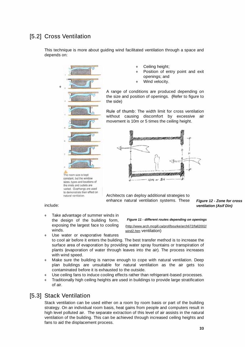
[5.2] Cross Ventilation
This technique is more about guiding wind facilitated ventilation through a space and depends on:
♦ Ceiling height; ♦ Position of entry point and exit
openings; and ♦ Wind velocity.
♦ A range of conditions are produced depending on the size and position of openings. (Refer to figure to the side)
Rule of thumb: The width limit for cross ventilation without causing discomfort by excessive air movement is 10m or 5 times the ceiling height.
Architects can deploy additional strategies to enhance natural ventilation systems. These
include: ♦ Take advantage of summer winds in
the design of the building form, exposing the largest face to cooling winds.
♦ Use water or evaporative features to cool air before it enters the building. The best transfer method is to increase the surface area of evaporation by providing water spray fountains or transpiration of plants (evaporation of water through leaves into the air). The process increases with wind speed.
♦ Make sure the building is narrow enough to cope with natural ventilation. Deep plan buildings are unsuitable for natural ventilation as the air gets too contaminated before it is exhausted to the outside.
♦ Use ceiling fans to induce cooling effects rather than refrigerant-based processes. ♦ Traditionally high ceiling heights are used in buildings to provide large stratification
of air.
[5.3] Stack Ventilation Stack ventilation can be used either on a room by room basis or part of the building strategy. On an individual room basis, heat gains from people and computers result in high level polluted air. The separate extraction of this level of air assists in the natural ventilation of the building. This can be achieved through increased ceiling heights and fans to aid the displacement process.
Figure 12 - Zone for cross ventilation (Asif Din)
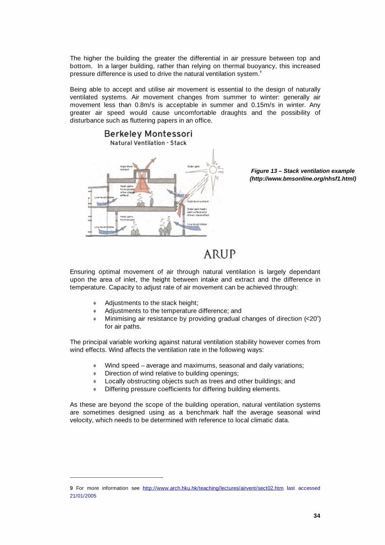
34
The higher the building the greater the differential in air pressure between top and bottom. In a larger building, rather than relying on thermal buoyancy, this increased pressure difference is used to drive the natural ventilation system.9 Being able to accept and utilise air movement is essential to the design of naturally ventilated systems. Air movement changes from summer to winter: generally air movement less than 0.8m/s is acceptable in summer and 0.15m/s in winter. Any greater air speed would cause uncomfortable draughts and the possibility of disturbance such as fluttering papers in an office.
Ensuring optimal movement of air through natural ventilation is largely dependant upon the area of inlet, the height between intake and extract and the difference in temperature. Capacity to adjust rate of air movement can be achieved through:
♦ Adjustments to the stack height; ♦ Adjustments to the temperature difference; and ♦ Minimising air resistance by providing gradual changes of direction (<20o)
for air paths. The principal variable working against natural ventilation stability however comes from wind effects. Wind affects the ventilation rate in the following ways:
♦ Wind speed – average and maximums, seasonal and daily variations; ♦ Direction of wind relative to building openings; ♦ Locally obstructing objects such as trees and other buildings; and ♦ Differing pressure coefficients for differing building elements.
As these are beyond the scope of the building operation, natural ventilation systems are sometimes designed using as a benchmark half the average seasonal wind velocity, which needs to be determined with reference to local climatic data.
9 For more information see http://www.arch.hku.hk/teaching/lectures/airvent/sect02.htm last accessed
21/01/2005
Figure 13 – Stack ventilation example (http://www.bmsonline.org/nhsf1.html)

35
[5.4] Checklist for Natural Ventilation Should work on still days and regardless of wind direction.
Openings should not be obstructed.
Openings should be the maximum vertical distance apart to increase pressure differences.
Consider low level opening on one side of floor and higher level opening at the other.
Horizontal distances should be examined to make sure air does not bypass occupied zones.
Elements such as overhangs can help or hinder air flow.
External planting can enhance air flow through the building.
Air velocities should be maximised for occupant conductive cooling in humid environments.
Doors and openings should be in the direction of the prevailing wind.
Openings should be fully operable by occupants.
Vertical shafts should be used to induce stack effect throughout the building.
Windows in pressure neutral zone should be minimised as they would have little thermal effectiveness.
Inlets and outlets should be of the same size.
Design Considerations
♦ Building and fire regulations (CBA 5% free area of floor area); ♦ Acoustic problems; ♦ Occupancy patterns; ♦ Automatic vs. manual controls; ♦ Lack of tools; ♦ Increased risk and doubling up of systems; ♦ Potential heat loss in winter; ♦ Direct solar control; and ♦ Fluctuation of interior environment.
Problems associated with Building Openings ♦ Safety; ♦ Security; ♦ Outdoor Noise; ♦ Dust and Air Pollution; ♦ Sealed Environment; ♦ Solar heat gain – shading is often required and become obstructive of
views and effective aperture size; ♦ Draught; and ♦ Occupant knowledge of the system.
There are some contexts where natural ventilation solutions may be considered inappropriate. Call centres, for example, usually characterised by high occupancy density may find the control systems for a mixed mode system impractical.

36
Tropical Environments In a tropical environment breezes should be used to provide comfort cooling. To take advantage of this requires preferably lightweight structures capable of opening to and sealing from the environment. This approach does require a high level of insulation and the ability to exclude warm winds and the ability to capture cooling breezes. As the air has high moisture content in tropical regions, air movement within the space becomes very important, so the natural ventilation openings should be kept as open as possible.
Office Issues
Partitions should be limited to 1.2m in height perpendicular to air flow. The use of tall partitions at the perimeter will deflect air in a naturally air conditioned office. Also the concentration of high heat gain equipment in under-ventilated areas should be
Having circulation areas around the perimeter should be considered as this allows a more democratic usage of the windows accessible for a greater number of occupants.
Example: ING building The building famously avoided air conditioning by using its massive 18" interior concrete walls and flushing with the cooler night air to advantage. This building was one of the first to report the productivity gains of a green building, such as lower absenteeism.' The Rocky Mountain Institute reports: 'The building uses less than a tenth the energy of its predecessor and a fifth that of a conventional new office building in Amsterdam. The annual energy savings are approximately $2.9 million (1996 U.S. dollars) from features that added roughly $700,000 to the construction cost of the building and was paid back in three months.' ING have claimed an average 15% reduced absenteeism, which could render calculating payback periods for employing green building design suddenly a far more rewarding exercise.
If it is possible to design high quality commercial buildings with the use of natural ventilation, louvers, fans and passive solar design, then why are we still employing expensive mechanical airflow systems that are damaging to the environment, our health and finances?
(Refer http://www.rmi.org/sitepages/pid208.php for a full case study by the Rocky Mountain Institute.)
ref: Patrick K. (2004) IEQ: Coming to a building near you. Property Australia, October 2004; Sydney.
Figure 14 – Plan partitions so as to not block flow of air through the building, or use low level partitions (Asif Din)

37
Trickle ventilators should be used to provide the fresh air requirement in winter without excessive loss of heat. Trickle ventilation deploys a small opening to allow air to slowly move into a space. This has been used in the Limerik County Hall in Ireland. (Refer http://www.sei.ie/uploads/documents/upload/publications/Limerick_case_study1.pdf for fresh air provision in winter).
Figure 15 - Limerik Country Hall Atrium
Retail Issues
Buildings have large heat gains (high density of lighting and people) with large entrances causing overcooling and draughts. Many retail spaces have deep floor plates making natural ventilation difficult to achieve effectively. The main aim would be to reduce the temporary air flow changes by using modifiers as radiant sources or air curtains adjacent to openings.
Equipment Layout Due to solar heat gain, the density of occupants along the north façade should be lower than that of the south façade. Heavily polluting equipment should be located in rooms with mechanical extract on the East or West facades where fenestration is typically minimised due to solar heat gain and glare being hard to control.
Figure 16 – building organisation
Limerik County Hall’s eye-catching atrium forms an essential part of its natural ventilation, standing full height along the entire length of the south-west façade. In summer, automatic openings in the atrium combine with manual and automatic openings in the offices to ventilate the main building and offset heat gain. During winter, trickle ventilation provides fresh air to the atrium. Its external solar shading reduces the unwanted solar gain and minimises glare, while offering adequate day lighting and views to the outside.

38
[5.5] Computer Modelling of Natural Ventilation As a range of different factors are in play in the use of a naturally ventilated system, the knock-on effects of changing an element are hard to predict. An appropriate computer model can optimise various elements with regards to other factors including geometry and building mass. While basic weather data can be used to calculate extremes, computer modelling will be able to give the results for the whole year based on weather data. It allows unexpected results, which sometimes occur during spring/autumn, to be investigated in more detail. Basic parameters after various iterations will point the design in the direction of the most low energy effective ventilation design. In computer modelling, the key parameters required are:
♦ Location of heating and cooling elements; ♦ Location of vents and extracts; ♦ Location of windows; ♦ Equipment and occupation density; and ♦ Geometry of floor plate including ceiling height.
Based on the parameters, temperatures and air movement are assigned for each of the natural ventilation, heating and cooling sources. As natural ventilation demands some user or mechanical manipulations of the openings and extracts, the locations and sizes of these openings should be given so the maximum and minimum free areas can be assessed on how well they work in the ventilation strategy when tied in with climatic data for the region. Various elements may require physical modelling to achieve the low pressure measurements required for a passive system. Salt bath can be used for this type of specific modelling though it tends to be very expensive. Computer modelling when carried out properly can assist in convincing clients of the applicability of a natural ventilation strategy, especially in terms of the Predicted Mean Vote (PMV) and Percentage of People Dissatisfied (PPD) (refer Section [2.2] for more on this). Modelling may indicate that full natural ventilation may not provide the ideal conditions and mixed mode strategies should be explored. Outputs from the modelling that will need to be reported are:
♦ Air exchange rates; ♦ Ventilation rates; ♦ PMV and PPD; ♦ Percentage of natural and artificial ventilation; and ♦ Energy consumption and greenhouse emissions.
[5.6] Natural Ventilation and associated Passive Design Strategies
A combination of strategies can be combined to provide more effective and efficient results, which become mixed mode systems.

39
Mixed mode systems demand smaller control zones so users can have mechanical ventilation in areas where climatic influences demand it (e.g. west facades). The mean effective temperature of the ventilation system should be determined using climatic data to find hours of mechanical fan operation required. This will produce a cost for the reduced sized system and determine whether the mixed mode system is effective in that climatic environment. Natural ventilation strategies can be combined to provide the desired effects: stack, wind and solar absorption. Stack and wind have been dealt with above. Solar absorption effect occurs when solar-heated air expands pulling cooler air into a collector to be heated and thereby initiatiating a continuous process. Wind and solar absorption effects introduce a degree of variability and require some measure of control. Often a damper would be fitted to cope with excess wind or solar gain at times. On the other hand, wind effect can entirely drop out in periods of negligible air movement.
Solar Chimneys Solar chimneys should be sufficiently insulated so that when dampers are closed excess solar incident heat is transferred and vice versa in cold winter air conditions. To design a solar chimney the first aspect that needs to be assessed is the total heat gain. This is a sum of the heat gains from the occupants, solar gain through windows, fabric solar gain, lighting and equipment. These effects can be assessed to estimate the potential effectiveness of a solar chimney strategy for the extract of hot air in the building. This is largely dependant on:
♦ Inlet and exhaust temperatures; ♦ Area of opening; ♦ Throat area of exit; and ♦ Combined wind and stack effect.
View through exterior courtyard of
solar chimney beyond.
Close up of exterior detail of
solar chimney.

40
View through main hall beneath
solar chimney.
View up into solar chimney.
Figure 17 – Images kindly used with permission of Terri Broak (University of Waterloo http://www.fes.uwaterloo.ca/architecture/faculty_projects/terri/sustain_casestudies/York_gallery.html)
Thermal mass Thermal mass uses the free cooling available when the outside air is cooler than that in the interior of the building. This strategy is only effective where there is a high diurnal shift between day and night temperatures. Heavy mass elements are able to absorb heat and re-radiate it into a building at a later time. Concrete provides a good thermal mass while plasterboard has little thermal mass effect. A minimum amount of concrete effective for diurnal heat storage is 50mm of high density concrete.
Figure 18 – CH2 passive design strategy using Thermal mass and night purging (Stephen Webb DeignInc Melbourne)

41
Figure 19 – CH2 precast panel
Shifting peak load Shifting the peak load so that the energy usage is more evenly distributed throughout the day allows the use of smaller plant and therefore less energy consumption. Shifting loads requires the storing of heat energy so that it can be reused or expelled. The simplest form of this is the use of thermal mass. Concrete buildings should be insulated on the outside with the concrete exposed to the interior. The concrete can absorb a certain amount of the heat during the working hours and re-radiated it during non-working hours. The building can then be flushed at night so that the mass is ready to absorb heat the next working day. This system only works in areas with diurnal shifts of temperature and so is unsuitable for tropical conditions.
Earth and Geothermal Conditioning The earth at below about 500mm is very constant in temperature and so can be used for the preheating or cooling of air before it enters the building. Boreholes and the use of geothermal heat work on the same concept although are quite expensive. Sometimes called earth pipes, the heating/cooling effect depends on the moisture content and soil type and varies throughout the year. Rock fill is a better thermal heat capacity medium and can be used to surround the pipe but this will add extra cost to a project. For further information refer to: The Geoscience Australia Building – ground source heat pumps http://www.ga.gov.au/about/corporate/agso_building.jsp http://www.ga.gov.au/about/corporate/building_features.jsp
Labyrinth In the case of a labyrinth an artificial tunnel is created with the maximum surface area for heat transfer. This allows parts to be closed off to provide an adequate amount of heating. This option should only be considered if it serves other engineering/structural purposes due to the amount of embodied energy contained in building such a structure.

42
Federation Square is an example of an effectively working labyrinth though it only cools the atrium space. For more information see the case study.
Figure 20 – Federation Square (http://www.atelierten.com/ourwork/fedSquare.asp)
Night time purge ventilation In an office building, the main aim is to use the thermal mass to absorb the incidental gains during the working hours and discharge the heat during unoccupied periods. This method only works well in climate zones with a lower external night time temperature than the interior of the building. In this case, air is used to cool the concrete elements in the building. This could be by forced ventilation using fans or by opening windows at night cooling the building ready to absorb heat at the start of the next working day (see Figure 19 above).
Night sky radiant cooling Natural cooling can also be provided by the use of evaporation and radiant night sky cooling. This is a method to produce chilled water for a chilled panel or air conditioning purposes. During the day the earth is warmed by the sun. At night the earth reradiates this daytime heat back into space which providing cooling potential. Space acts like a black body and the effective cooling potential of the clear night sky is around 10-15oC cooler than the ambient air temperature. Factors that affect this cooling potential include air temperature, moisture content and cloud cover. These reduce the night cooling potential dramatically. Dry clear nights provide the best potential for this method. Radiant night cooling can be used where there is a high incidence of clear nights in summer. Water is spayed onto the roof at night and is cooled by the night sky this is then collected and used in the conditioning systems the next day. Space has to be allowed for these shower towers and monitoring for when they can be used most effectively. This has the added advantage that the system can be incorporated with a rainwater collection system. More information see: Fact sheet at: http://www.eere.energy.gov/inventions/pdfs/integratedcom.pdf Installation guide: http://www.pnl.gov/TechReview/pdfs/WhiteCapTechInstall.pdf

43
[6] MECHANICAL VENTILATION, HEATING & COOLING The most important issue for mechanical ventilation is determining exactly what the client’s needs are for comfort in their building and taking stock of what natural ventilation opportunities are available and feasible. This section addresses:
[6.1] Considerations for Ventilation Systems ♦ Mixed Mode Ventilation (Natural & Mechanical) ♦ Computer Modelling – Mechanical Ventilation ♦ Checklist of Economising HVAC
[6.2] Dehumidification [6.3] Heat Exchangers [6.4] System Design
♦ Leaks ♦ Insulation ♦ Zoning
[6.5] Lower Pressure Systems ♦ Larger Ducts ♦ Circular Ducts ♦ Reduce Bends for Efficiency ♦ Efficient Diffusers
[6.6] Displacement Ventilation (UAD)
[6.1] Considerations for Ventilation When designing a ventilation system three systems can be employed:
♦ Natural ventilation ♦ Mechanical ventilation ♦ A mixed mode system
Natural ventilation systems are covered in the previous section on Natural Ventilation. In certain circumstances a natural ventilation system cannot satisfy the entire occupants’ requirement for thermal comfort. Mechanical ventilation systems should only be used when necessary in such places as libraries, computer rooms and laboratories.
Mixed Mode Ventilation (Natural & Mechanical) Mixed Mode describes a system that provides both passive and active cooling, heating or ventilation with the operation of either system being determined by seasonal or daily variation of ambient temperatures. Mixed mode ventilation systems, including mechanical methods or components are suitable for most commercial projects. This should not mean two systems are installed instead of one. Some zones such as circulation spaces have less strict thermal requirements which provide potential for naturally ventilated zones within the building. Before starting to assess the air conditioning plant size for a building, a natural or mixed mode potential for a certain part of the year needs to be assessed. This can be done by matching climatic data with thermal comfort conditions to see if conditioning of air can be done by natural means. If these methods cannot be used then a mechanical system of supplying air to the building is required.

44
In a mixed mode system, natural ventilation to be used for the most part and can be supplemented by a mechanical system. This requires smaller control zones to take into account external influences. The switch-over point is very fuzzy requiring complicated automated systems or an educated user to close windows to allow a mechanical system to activate. A traditional HVAC design system can be designed to consume less energy in a range of ways. Each needs to be considered as part of the system design and not considered as a kit of parts to be added together.
As a general rule, the greater the fresh air supply to a workspace the better the productivity and the comfort of the internal environment, provided the air is properly conditioned. Adequate air mixing in the building must be designed for so effective air replacement can take place to avoid static air pockets. This will remove stale polluted air, replacing it with fresh air and reducing sickness in office workers.
Where automated systems are used, a carbon dioxide monitor should be installed and the system designed to automatically supply more fresh air to those areas of high carbon dioxide concentration.
Computer Modelling – Mechanical Ventilation This is closely related to the comfort levels experienced within the building. With parameters such as the location of supply and extract, and the air supply rate, computer modelling assess occupants’ comfort level in terms of the effectiveness of air mixing, temperature and draught conditions for the occupied zones modelled. Parameters required to carry out computer modelling are:
♦ Location of heating and cooling elements; ♦ Location of vents and extracts; ♦ Location of windows; ♦ Equipment and occupation density; and ♦ Geometry of floor plate including ceiling height.
From these, a map of temperatures and air movement can be established with differing hours of operation to show how effectively the ventilation system is working. The temptation to overpopulate the building, and hence over sizing of the ventilation system, should be avoided and advice sought from the client to see what actual equipment and workspace occupation patterns are.
[6.2] Dehumidification The traditional method of dehumidification is to cool the air down so that it possesses less moisture content prior to reheating. This is wasteful of energy. Tt is better to use a reusable agent such as a desiccant wheel.
A desiccant system comprises a heat exchanger, a desiccant wheel and two evaporative coolers installed in a standard air handling unit. The ambient air enters the desiccant wheel where it is partly dehumidified with a rise in temperature. The treated air then passes through a sensible heat recovery wheel where it passes through the evaporative cooler to be cooled further. It does pick up moisture but remains below the dew point temperature for the desired internal air condition.
The return air passes through the second evaporative cooler where it is cooled and picks up moisture. It then passes to the sensible heat recovery wheel to provide

45
coolth to incoming outside air. The air is then heated further by waste heat before passing through the desiccant wheel, regenerated, then discharged to the atmosphere. Many suppliers combine the sensible heat recovery wheel with the desiccant wheel in one unit.
[6.3] Heat Exchangers Heat exchangers reuse the waste heat from the stale outgoing air with the air intake. Many different heat exchangers exist including in-flow, counter-flow and cross. Cross-action heat exchangers provide the most efficient operation10. Different heat exchangers are required for different operations in the system and should be part of the initial design to gain its maximum potential in the reduction of sizing other equipment.
[6.4] System Design
Leaks Leaks have a detrimental effect on the efficiency of any conditioning system. They also may have a health and safety consequence depending on the refrigerant used. Leak detectors should be installed so any leaks are reported quickly and refrigerant is conserved rather than replaced.
Insulation Distribution losses in the system can be minimised with properly insulated and sealed ductwork and particular attention should be paid to junctions and bends. The protection of any air conditioning equipment from solar gain is important, as extra solar load placed on equipment may lead to equipment sensors giving false readings resulting in overcooling of spaces.
Zoning Zoning is of particular importance when designing for energy efficiency. This may be a flexible system that would take into account changes in layout and cellular offices. In the case of open plan arrangement, a perimeter will be zoned separately from an internal zone due to façade influences.
The Architect should discuss with the mechanical engineer:
♦ When using VAV outlets, it is important to specify zones designed
specifically for VAV systems and avoid fan-assisted outlets, which adds complication to the control mechanism.
♦ The application of self-actuators rather than boxes/slot diffusers is preferable.
♦ Calculation of supply rates needs to be conducted rather than relying on rules of thumb for minimum supply rates.
♦ Use separate return air flow control independent of supply air static pressure control loop for the balance between supply and return circuits.
♦ Use backward curved centrifugal fans and solid state variable speed drives.
♦ Use static regain duct calculation method.
10 For more information see http://www.aexusa.com/nvdv.htm#how

46
♦ Zone areas correctly including cellular, perimeter and internal open plan zones and take into account orientation and the building fabric.
[6.5] Low Pressure Systems Any ventilation system should be designed to minimise pressure in the system, as low pressure systems are more energy efficient to operate. The ventilation rate is a key determinant of pressure in the system and can directly impact on the size and energy consumption of the ventilation system. An increase in the ventilation rate requirement, for example, as a result of the additional thermal loads and pollutants caused by office fit-out, furnishings and equipment, would raise the pressure and compromise the energy efficiency of the initial system design.
A lower pressure system can be achieved by:
♦ Allowing spaces for larger diameter ducts ♦ Using circular ducts where possible; ♦ Reducing the number of bends and places of transition; ♦ Checking that most effective diffusers are used for the reduced
velocities.
Larger Ducts A lower pressure system needs less energy to run as it operates at a lower velocity. This means that the system is sized with a larger diameter of ducts that in turn reduces frictional losses and is reflected in the smaller sizing of fans and chillers.
Circular Ducts Using circular rather than square ducts to reduce turbulence as the corners create turbulent zones. Use of correct diffusers and baffles ensure that air is transferred to the occupied spaces as required. The Air Diffusion Performance Index (ADPI)11 is a measure of how the system performs in a certain space in delivering air within a range of temperature and velocity range for comfort12.
Reduce Bends for Efficiency Reducing bends in the system will also improve system efficiency and reduce plant component sizes with the proper use of correctly sized dampers and reflectors. The outlets need to be properly specified to give the correct amount of throw, velocity and control otherwise this will lead immediately to user dissatisfaction.
Efficient Diffusers The most efficient diffusers should be used for the job required whether they are high induction or spiral action to give the most effective coverage for the amount of diffusers in a space.
[6.6] Displacement Ventilation (UAD) Here ventilation supply is located at the bottom of a space and by natural thermal buoyancy picks up pollutants and is extracted at high level. It relies on the thermal
11 For more information see http://www.tuttleandbailey.com/techcorner/bulletins/basics.asp
12 The ASHRAE Handbook states that “for an office environment in cooling mode, the design goal should be an ADPI of greater than 80.”

47
stratification of air providing comfort temperatures in the occupied zone. The system is more broadly defined as an erfloor air distribution (UAD) system. This is due to the use of plumes, which rise then fall causing better mixing than having displacement, low-velocity and low-pressure outlets. When a steady system is obtained, the air moves slowly up the space drawing in more fresh air from below causing an even stratification between the lighter polluted air and the denser cooler fresh air. Factors to consider when designing UAD systems:
♦ Make sure there is enough free space in the underfloor system; ♦ Fit terminals with debris baskets so cleaning of the underfloor space is
reduced; and ♦ Floor tiles can be coordinated with terminal panels so that terminal tiles
can be moved to where they are required.
A displacement ventilation system can supply air at 18oC and return at 26oC. An overhead system typically supplies air at 12oC and returns at 24oC (Graham G, “UAD system implementation”, AIRAH Conference 17 September 2003)
Displacement ventilation uses the natural convective movement of air to get rid of pollutants in the office. In this way, air can be supplied at a lower temperature for heating and higher temperature for cooling. This reduces the sizing of ventilation equipment compared to a conventional system.
Figure 21 - Displacement strategy using natural heating of elements to get rid of pollutants from an office (Asif Din)
Using displacement ventilation through large ducts, low velocities and lower temperature ranges will reduce energy consumption. It will also cause lower pressure drops across the system resulting in the reduction of system noise.
This has a range of advantages over a conventional overhead system with improved robustness and less complicated VAV design. It also allows flexibility in churn by having the ability to move floor vents with local personal control, as each terminal can be adjusted to supply air towards or away from occupants. The terminals catch debris in a basket arrangement damper and can be modularised to suit the size of floor tiles allowing convenient relocation and replacement.

48
Many offices use a raised floor system for distribution of communications and electrical wiring, the UAD (in range of 300-400mm) can be accommodated within existing raised floor systems as long as clear air paths exist (minimum 75mm) and can be coupled with the exposed concrete slab for pre cooling before air reaches terminal outlets. In new office projects, this can reduce floor to floor heights with bulkheads required for return air ducting rather than a full suspended ceiling. Energy savings compared to a conventional system occur due to more usage of the economiser cycle (with higher return temperatures of 25-30oC dry bulb and higher supply temperatures of 16-18oC dry bulb), increased chiller Coefficient of Performance (COP) and fan energy savings by reduced air volume and lower static pressure requirements. An overhead system has to provide air supply at a lower temperature at 12oC and return at 24oC13, and require higher pressure and volume to get correct mixing to occur. This results in the economiser being used for a lower proportion of the year than a UAD system.
Benefit of Radiant Systems Radiant heating and cooling is more effective in comparison to traditional convective systems that require fans to blow conditioned air into the space. Chilled ceiling panels can be used to provide cool conditions on hot summer days, but are not as suitable in humid environments due to condensation problems. Chilled beams using the same technology can be used to provide cooling near windows to counteract solar heat gain. Heating and cooling in a traditional HVAC convective system are quite inefficient relying on movement of air over hot or cold surfaces. Radiant systems are more responsive in modifying air conditions and the adjustment can be more readily felt by the occupants as this method is more in tune in the way the body works.
Cooling Systems
Shower Towers These supply direct evaporative sensible cooling to reduce air temperature in non-humid air conditions. The air can only be cooled by its capacity to absorb water until it is fully saturated. In humid conditions this becomes ineffective due to the high relative humidity of the air.
13 Building Delivery ZONE at Sydney Olympic Park, C. Lovejoy, AIRAH ESD conference 2 September 2004

49
Figure 22 – CH2 (Design Inc)
The CH2 project employs shower towers, which work by drawing in outside air from 17 metres above street level and channelling thin into the shower towers on the south side of CH2. The towers are made from tubes of lightweight fabric 1.4 metres in diameter. As the air falls within the shower tower it is cooled by evaporation from the shower of water. Other similar systems include spaying the roof at night where the water is stored in a tank to provide a passive storage system. This tank storage can also be part of a rainwater system. This water can be used to provide the pre-cooling required for air conditioning systems. The combination of a rainwater storage system and a stratified tank for the storage of radiant night coolth should be investigated for potential.
Case study – Essendon Baptist Community Church14 - The church could not artificially cool a 400-seat auditorium and the associated spaces, so night sky cooling system was explored. As the church was used only one day a week, the chill water required to provide cooling for the next event can be generated over the remaining week.
Water is sprayed onto the roof and collected in the rainwater storage system. Of the two tanks located in the basement of the building, one is used for cooling and the other for toilet flushing and irrigation of the site.
The system satisfied the peak cooling requirements without the use of refrigerants by using an underfloor heating and cooling system placed in the screed of the floor (used as a medium to provide radiant cooling) and a displacement ventilation system using 100% fresh air. A possible upgrade could include using the chilled water for the pre-cooling of outside air before it enters the building during peak hours. 14 Active Building Structure and Night sky Radiant Cooling, S Esmore, AIRAH ESD conference, 2
September 2004

50
Chilled Technologies This includes the use of chilled beams, panels and ceilings. These can offer significant advantages in terms of energy, thermal comfort and indoor air quality. They generally use water-based heat transfer eliminating the requirement for a traditional air transfer system that is energy inefficient by comparison. These chilled systems can achieve the same comfort range by supplying air to occupied spaces at higher temperatures and thereby reducing the energy required to cool fresh and return air which in turn reduces the plant and equipment size required. Chilled technology comes in a variety of forms:
♦ Passive chilled ceilings; ♦ High capacity chilled ceilings; ♦ Chilled beams – active and passive (convective and radiant/convective); ♦ Thermal ceilings.
In chilled ceilings, water is usually circulated at 14-17oC compared to an air system of 6oC (Henderson, AIRAH 2003) to minimise condensation and the sensors would automatically switch off an element in conditions where condensation could occur. These systems usually consist of metal perforated panels with chilled water circulating behind and mineral mats are used to absorb the noise generated by water circulating in the system. Chilled ceilings can also be used in a reversible process using the same system for radiant heating. In a radiant system, air is cooled and falls, but because air velocities are lower than a traditional system, occupants’ perception of thermal comfort is improved, as a radiant source is more in tune with the perceived bodily heat transfer.
Figure 23 – Chilled Multi Service Beams – light, comms and coolth (AEC CH1 workshop)
The cooling capacity for a chilled ceiling is a function of the difference between the temperature of the ceiling and that of the occupied zone. This is typically 10W/m2 for every 1K. The mechanism of cooling is 60% radiation, 30% convection and 10% evaporation via a dehumidified air supply.

51
Chilled beams can either be recessed or suspended below the ceiling. For more effective cooling, chilled elements should be exposed to the room. Chilled beams use a linear finned element encouraging warm air to pass over it, and fall into the occupied zone by negative buoyancy when the air is cooled. This could either be a passive system or an active arrangement introducing air over the coil. The active beams have an induction ratio of up to 5:1 so that 2 l/sm² equates to a total delivery 10 l/s m2.
Figure 24 – Chilled beams and ceiling panels CH2 (Stephen Webb, DesignInc Melbourne)
Chilled beams have a reduced radiant effect, as the cooling surface does not directly influence the occupants. This does allow higher air temperatures and lower air velocities compared to a traditional HVAC system. However, it is more like an air system than chilled ceiling system with some capacity limitation. Typical heat exchange is achieved by 10-20% radiation, 70-80% convection and 10% evaporation. The output for chilled beams can be as high as 600W/m but capacities over 250W/m are likely to cause downdrafts. Chilled beams should be modelled to check if air velocities would cause discomfort to occupants. Beams are usually used at the perimeter of floor plans to counteract solar heat gain and chilled ceilings or panel used in the centre of floor plates. A chilled system has a lower supply rate and lower pressure than an all air system achieving around 20% energy saving in fan power. In addition, due to higher return temperatures, chiller plants can achieve a COP of 7-10 providing associated energy savings. Chilled elements are simple water to air heat exchangers. The overflow of water achieves little excess capacity but underflow may noticeably affect the desired load capacity. Self-regulation occurs due to the chilled element capacity being proportional to the fluid temperature difference. Therefore, if the internal loads are higher, more heat is transferred and the same effect occurs when the load drops. There is however a time lag of two hours for a 2-3oC room temperature rise.
52
Storage Systems
Phase Change Materials (PCMs) Certain materials change from liquid to solid with an input of energy. This thermal energy can be stored and used at a later date. Water can be considered to be a PCM at 0OC. Other salts and materials have values around 20OC making them more useful for building services applications. PCMs can be impregnated into building materials effectively making plasterboard act like a thermally massive concrete slab15, or in a centralised storage system that can be modularised for holding coolth until required.
New Innovation in this area is the use of PCM in double glazing. The main challenge with PCM at the moment is cost. For more information see:
♦ Weinlader, H, Beck, A & Fricke, J 'PCM-facade-panel for daylighting and room heating', Solar Energy, vol. In Press, Corrected Proof.
♦ Ismail K. A. R., Henríquez J. R. (1998) ‘PCM glazing systems’ International Journal of Energy Research Volume 21, Issue 13, Pages 1241 – 1255
Ice Storage An application of the PCM principle is ice storage and chilled water storage. This uses off-peak electricity supply to store chilled water or ice for use the next day and thereby reduces the peak demand. The electricity used would be on a reduced tariff. Further energy efficiency can be achieved by using passive means to achieve chilling of water overnight. The bigger the system for chilled water storage the better, which suggests that this method would be highly suited to district cooling systems provided that distribution losses are minimised through insulation and leak protection.
In comparison to building-based chillers, cooling towers and control systems, a centralised system saves on floor areas required, plant and equipment numbers and chiller sizing, as well as simplified maintenance routines.
Case Study – Chilled water storage at Charles Darwin University – By using off-peak electricity, a peak load shift of 1.5MW was achieved. Ice storage proved too expensive but a stratified chilled water system was employed. The stratified water tank is 8.6ML serving 42 buildings with a total floor area in excess of 80,000m². This centralised system always runs at full capacity during off-peak hours.
Since its commissioning in late 1998, the chilled water thermal energy storage system has functioned without fail. It has improved reliability and has required little attention from facilities management staff and has been continuing to achieve energy cost saving as initially estimated.
(Refer http://www.airah.org.au/downloads/2004-11-F03.pdf for further information.)
15 for more information see
http://utwired.engr.utexas.edu/siegel/final%20project/Symposium/Liu%20Paper-05-04.pdf

- 53 -
[7] NATURAL AND ARTIFICIAL LIGHTING If the use of natural daylight in a building can be maximised, reliance on artificial lighting can then be minimised and only used to supplement for certain tasks. This would lead to a reduction in electricity used and an improvement in the indoor environment quality. However, it is important to remember that there needs to be a balance between natural light and the heat load as high daylight levels usually coincide with the peaks in cooling loads.
Daylight is an extremely powerful light source providing around 5,000 lux on an overcast winter day compared to 300 lux falling on an average office desk. Daylight also has a psychological effect as it contains all frequencies of light unlike artificial light, which tends to concentrate in particular spectral values. This section addresses:
[7.1] Views to outside increase productivity [7.2] Daylighting Strategies [7.3] Daylight Glare Control [7.4] Computer Modelling [7.5] Artificial Lighting
Other References on Lighting
BDP Environmental Design Guide DES 62 “Integrated Design Process Incorporating Lighting” by Mark B
Luther, August 2004. DES 63 “A Basic Guide to the Daylighting of Buildings” by Steve Coyne
and Gillian Isoardi, November 2004. Whole Building Design Guide – Daylighting, by by Gregg D. Ander, FAIA,
http://www.wbdg.org/design/daylighting.php, last accessed on 17 October 2005.
[7.1] Views It is preferable to have a view to outside from a desk position not only for daylight purposes but also for the reduction of eyestrain with the opportunity for occupants to adjust their eye focussing between near and far objects outside of windows.
A good rule of thumb is to have all desks within 8m of a window with a view.
Figure 25 - A 8m zone to an outside view is preferable in an office building (Asif Din).

- 54 -
[7.2] Daylighting Strategies
Light can be admitted into a building through a range of devices. The larger the window the more light is admitted. In letting in daylight, direct sunlight which provides a heating load on the building should be minimised except if required for heating purposes. Direct sunlight is much brighter than daylight which can also cause discomfort to the occupants.
Although direct sunlight may be preferred in winter when there is a heating requirement, in summer it quickly results in overheating. Sunlight being so variable and hard to control in terms of glare and reflections off of monitors, it should be excluded from most office building designs.
Atriums or light wells allow diffused daylight from above to enter a building. This provides a more constant and even lighting with minimal solar heat gain and allows daylight to penetrate further across floor plans than normally possible.
Figure 27 - School of Architecture and Design, Victoria University of Wellington, Wellington, New Zealand (http://www.vuw.ac.nz/architecture/facilities/index.aspx)
Open-plan offices with partitions should ensure that the partitions near windows should be as low as practicable. If acoustic privacy is required as in the case of cellular offices, the use of high-level glazed partitions will allow light to penetrate.
TIP
Generally windows should be placed in a zone 600mm above finished floor level and 2100mm to top unless a strategy of daylight displacement is used (eg. light shelves).
Figure 26 - Ideal placement of window for maximum usage without excessive heat gain/loss (Asif Din)

- 55 -
Roof lights or skylights can be used to provide diffused daylight. This is usually achieved by orientating them on a southerly slope to avoid direct solar heat gain. This however is only available to floor or section of floors that have a roof.
All glazed opening units should have a weather seal to reduce heat loss through uncontrolled ventilation. Window and door frames should be made of an insulative material or thermally broken to reduce the amount of heat transfer from the building. As a general rule of thumb, daylight will penetrate 6m into the plan of a building. A range of elements can be used to increase the daylight factors in a building. These fixtures make the maximum use of the sun as the source of natural light.
Light shelves with a reflective upper surface can be incorporated as part of a horizontal shading system part way up an opening. Light shelves work by bouncing light deeper into the plan but exclude direct sunlight from perimeter locations.
External blinds help bounce light from the openings to the ceiling plane using the ceiling surface to reflect more daylight into the building. This works similarly to light shelves in front of a window.
The devices above could be very simple or can be complex by the use of sun tracking systems to shade and diffuse the maximum amount of light. A cost comparison needs to be made between an initial capital cost required for installing a computerised system compared to the saving of the reduced load on cooling systems and lighting loads. This would require lifecycle costs and payback period to be calculated. Ceiling forms to maximise the effect of light shelves and external blinds can be designed to reflect and modulate bouncing of light deeper into floor plans.
Limitation of Daylighting Strategies Overheating due to direct transmission of daylight into an interior space needs to be avoided. This would usually involve exclusion of direct sunlight. However, as the sun’s angle varies over the course of a year, it may be difficult to exclude all hours of direct sunlight.
Figure 28 - computer model of the office spaces with precast concrete ceiling-floor system (DesignInc)

- 56 -
Generally speaking, overhang or eaves to northern facades would provide protection against direct sunlight through the openings. On the eastern and western facades, a combination of horizontal and vertical shading devices may be required to minimise morning and afternoon direct exposure and the low-angle sun in winter. Southern façade glazing usually requires little shading or some vertical shading when the sun is low in the sky.
It should be noted that ineffective shading is not unlike inadequate lighting and can lead to occupant discomfort.
[7.3] Daylight Glare Control An efficient daylighting design, in addition to providing illumination sufficient for good visual performance, is also essential in maintaining a comfortable and pleasant atmosphere. Glare occurs where there is excessive brightness contrast within the field of view, which is an aspect of lighting that can cause discomfort to office occupants and compromise productivity. While the human eye can function quite well over a wide range of luminous environments, it does not function well if extreme levels of brightness are present in the same field of view. Presence of glare or excessive contrast in brightness actually reduces visibility and causes eyestrain over time as the eyes try to adjust to the excess brightness or between areas of different brightness. Because of the sun’s angle and path through the year, it is difficult to design a glare-free environment whilst maximising openings in the building envelope to allow daylight to come in and views to outside. However, it is important to avoid direct beam daylight on critical visual tasks, including reflections off computer screens. Devices such as light shelves and external blinds can be designed to provide diffused daylight to maximise room brightness and at the same time decrease window brightness, which is a major source of glare and cause of reflections off surfaces. User controls over external shading devices or internal blinds as part of the daylighting systems also add the overall adaptability of the office environment. Productivity also improves where occupants feel that they have control over their environment. Glazing specification can also assist in controlling the transmission of daylight into interior spaces. There is now a wide range of tinted or coated glass with differing luminous efficacy available commercially that can be used to control the amount of daylight transmissible through the glazing system. Many of these products can also reduce solar heat gain as they lower the transmission of infrared radiation, which is at the low end of the light spectrum that provides no luminous effect but adds to the cooling load requirement in summer. Different glazing product and systems also have varying U-values which measure the rate of heat transfer or the rate at which thermal energy is conducted through the material. For example, double-glazing systems would have a lower U-value than a single-glazing system of comparable materials, as the transfer (or loss) of heat would be significantly reduced.
[7.4] Computer Modelling
The daylighting design concepts need to be assessed to provide a prediction of how the daylighting will perform in a space. The assessment would need to include

- 57 -
prediction of lighting levels achievable for different areas and estimates of solar heat gain throughout the day and the year.
There is wide range of daylight simulation softwares available on the market. The high level software packages are particularly useful in the later stages of design as they can provide relatively accurate simulations to reflect the design development changes and finetuning, such as building orientation, size and location of openings, and interior furnishings. Software packages are available, which are physically-based rendering tools. A lighting engineer or a specialist would be required to operate the software properly in order to produce meaningful results.
The packages have modelling and rendering capacity and provide a reliable tool in aiding design development assisting in:
♦ accurate calculation of luminance; ♦ ability to model both electric light and daylight; ♦ ability to support a variety of reflectance models; ♦ ability to support complicated geometry; and ♦ ability to take unmodified input from CAD systems.
However, computer modelling exercises can be expensive and the level of detail required is more suited for projects that have progressed to the design development phase as well as for projects adopting a combination of daylighting strategies where there combined effects may not be so obvious. For most effective overall project results, it is recommended that daylighting modelling be run in conjunction with thermal modelling so that occupant comfort and energy efficiency are also taken into consideration holistically in lighting design.

- 58 -
[7.5] Artificial Lighting While the importance of daylighting in sustainable office design is apparent, the design of artificial lighting is just as significant as it is unlikely that an office can completely rely on daylighting throughout the office operating hours year round. In fact, artificial lighting in office environments is a major area of energy consumption. In the United States, electric lighting accounts for 35% to 50% of the total electrical energy consumption in commercial buildings. Like other aspects of an office designed discussed thus far, artificial lighting design of an office environment also needs to integrate with daylighting strategies. Energy efficiency measures in lighting would also contribute towards lower cooling load on the HVAC systems and reduce energy consumption. Key factors in artificial light design are:
♦ Light sources and their efficacies; ♦ Light distribution and fixture design; ♦ Light colour and filtering; and ♦ Zoning layout and controls.
New luminaires like high frequency ballasts are superior to conventional fluorescent and incandescent luminaires as they do not cause flickering perceptible by some people or give large amount of heat warming up the environment unnecessarily. High frequency ballasts also have prolonged lamp life leading to direct operating benefits.
Optimal lighting levels required vary depending on the tasks. An average lighting level of 320 lux is recommended for visual display terminals (VDT) or computer screens, though the range can be 300-500 lux depending on the specifics. Generally reading would need between 500-700 lux depending on the size of the print and the eye condition of the reader. General ambience lighting in an office environment should take into consideration the tasks to be performed. It is also important not to over-provide lighting as too bright an environment can also cause occupant discomfort and it is not necessary to have lighting levels suitable for reading everywhere when only it is required for a percentage of an office floor plate.
Lighting fixtures and their distribution should be examined so there are no dark or extra bright patches as a result of the insufficient coverage or crossover. Designers should also note the average height level of the tasks are to be performed at for targeting of lighting levels required. Office layout and future adaptability should be considered in zoning of lights. This may including switches and control systems that allow dimming, dual-level and multi-level lighting as the level of lighting required to support daylighting where available would be different depending on the time of the day and on weather conditions. Overall, there are health benefit, energy efficiency and improved operating costs to be gained out of integrated lighting design to ensure that proper lighting levels are provided for occupants to carry out their tasks by opting for more energy efficiency light fittings and fixtures. Furthermore, detail studies of lighting usage can inform better office zoning and design of control systems that would in the long run contribute towards operational cost savings. References
BDP Environment Design Guide
DES 62 “Integrated Design Process Incorporating Lighting” by Mark B Luther, August 2004.

- 59 -
GREEN STAR – OFFICE DESIGN CREDITS AND THE ARCHITECT
Management
Code Criteria Architectural Role When to implement
Case Study
Purpose
Man-1 Employ Green Star Accredited Professional
Discuss this as part of project scoping at tender stage.
Initial discussion with client
CH2 Supports integrated design.
Man-7 Waste Management
Integrate requirement for Waste Minimization Plan in documentation.
Documentation ad construction
CH2 Supports good practice in construction and initiates procurement processes to reduce waste handling costs.
Indoor Environment Quality
Code Criteria Architectural Role When to implement
Case Study
Purpose
IEQ-1 Ventilation Rates Ensure mechanical engineer optimises ventilation rates initiatives.
Design development
CH2 Supports thermal comfort and occupant productivity.
IEQ-2 Air Change Effectiveness
Ensure mechanical engineer optimises air change effectiveness
Design development
CH2 Supports thermal comfort and occupant productivity.
IEQ-4 Daylighting Design in as much daylight as possible while minimising heat load.
Concept design CH2 Minimises energy consumption and supports occupant health and wellbeing.
IEQ-5 Daylighting glare control
Design in occupant controlled external blinds.
Concept design CH2 Minimises energy consumption and supports occupant health and wellbeing.
IEQ-5 Daylighting glare control
Design in occupant controlled external blinds
Concept design CH2 Minimises energy consumption and supports occupant health and wellbeing.
IEQ-8 External view Design office where desks are 8m or less from windows.
Concept design CH2 Productivity benefits.
IEQ-12 Internal Noise Levels
Brief mechanical engineer on required noise levels (design for sound level between 40-45 dB LAeqT in general offices areas and 35-40dB LAeqT in private offices).
Design development
CH2 Productivity benefits.
IEQ-13 Volatile Organic Compounds
Minimisation of potential VOC emissions from paints, carpet, sealants and adhesives.
Design development
CH2 Health and productivity benefits.
IEQ-14 Formaldehyde Minimisation
Use of no or low emission composite wood products.
Design development
CH2 Health and productivity benefits.
IEQ-16 Tenant Exhaust Riser
Design needs to show that there is a dedicated tenant exhaust riser providing 0.2l/s/m2 and potential of 0.5/s/m².
Design development
CH2 Health and productivity benefits.
Transport
Code Criteria Architectural Role When to implement
Case Study
Purpose
Tra-1 Reduce car parking
Design in minimum of car parks. Concept design and design development
CH2 Encourage alternative transport modes.
Tra-2 Small car parking
Design in 25% small car spaces (2.3*5m).
Concept design and design development
CH2 Encourage more efficient cars.
Tra-3 Bike Parking Design in bike parking for 5-10% of staff, equivalent number of lockers and 1 shower per 10 parks, and for visitors.
Concept design and design development
CH2 Encourages bicycle riding.

- 60 -
Materials
Code Criteria Architectural Role When to implement
Case Study
Purpose
Mat-1 Recycling Waste Storage
Design in adequate area of waste storage and separation (0.35% on NLA).
Concept design and design development
CH2 Waste minimisation and support s recycling.
Mat-2 Re-use of Facade
If refurbishing a building reuse as much of the façade as possible.
Concept design and design development
CH2 Waste minimisation and resource conservation.
Mat-3 Re-use of Structure
If refurbishing a building reuse as much of the structure as possible.
Concept design and design development
CH2 Waste minimisation and resource conservation.
Mat-4 Shell and core or integrated fit-out
Design and document either shell and core or integrated fit-out delivery.
Design documentation
CH2 Waste minimisation and resource conservation.
Mat-5 Recycled Content of Concrete
Specify concrete with 30-60% of extender and aggregate for 75% of concrete.
Design documentation
CH2 Minimise material impact. Resource conservation. Support greenhouse gas emission abatement.
Mat-6 Recycled Content of Steel
Specify steel which has 60-90% recycled content..
Design documentation
CH2 Minimise material impact. Supports greenhouse gas emission abatement.
Mat-7 PVC Minimisation
Specify non PVC alternatives 30-60% by cost.
Design documentation
CH2 Minimise material impact.
Mat-8 Sustainable Timber
Specify 60-90% of timber to be FSC certified, recycled or from good wood guide.
Design documentation
CH2 Minimise material impact.
Land-use and Ecology
Code Criteria Architectural Role When to implement
Case Study
Purpose
Eco-1 Ecological Value of Site
If part of the project before site selection, select a site, which is not on prime agricultural land or 100 metres from a natural wetland.
Client briefing CH2 Protect land of ecological significance
Eco-4 Change of Ecological Value
Work with design team to enhance ecological value of the site.
Design development
CH2 Increase ecological value of land
Eco-5 Top Soil & Fill Removal from Site
Specify in documentation that soil from site should be retained and used on site .
Design documentation
CH2 Preserve local soil ecology
Emissions
Code Criteria Architectural Role When to implement
Case Study
Purpose
Emi-7 Light Pollution Design lighting strategy to ensure there is no light beyond boundary.
Design development & documentation
CH2 Reduce impact on breeding cycles of fauna
Emi-9 Insulant ODP Specify the insulation materials use no ODS (Ozone Depleting Substances) in their manufacture.
Design development & documentation
CH2 Reduce impact on Ozone layer
Innovation
Code Criteria Architectural Role When to implement
Case Study
Purpose
Inn-1, Inn-2, & Inn-3
Innovation
There are 5 points for the use of innovative solutions. Points are given under:
− Innovative strategies or technologies;
− Exceeding green star benchmarks; and
− Environmental design initiatives.
Concept design and design development
CH2 Any of the above

- 61 -
GREEN STAR – OFFICE DESIGN ARCHITECTS’ GUIDE
MANAGEMENT
Man – 1 ‘Green Star Accredited Professional’ Points available: 2
Stage of the design process: Concept Design
Architect’s role: Explain the benefits to the client of employing a Green Star Accredited Professional
Activities that need to be undertaken:
Step 1: Explain the role of a Green Star Accredited Professional to the client. Step 2: Develop a vision for the building with the client if the Green Star
Accredited Professional was involved. Step 3: Define the extent of the role the Green Star Accredited professional will
play – write up the roles and responsibilities. Step 4: Ensure that they are appropriately resourced to be involved in the project
from the beginning and through the compliance phase. Benefits of employing a Green Star Accredited Professional:
1. Provide an understanding of the intricacies of Green Star – Office Design; 2. Has a solid knowledge for achieving the credits most effectively provided he
or sheet is involved from the start of the project; 3. Participation in the design process and assuming the role of coordinating the
integration of sustainability to ensure that best practice is applied; 4. Assistance with the coordination required to validate the point claimed.
Relevant sections:
Integrated Design Process
Man – 7 ‘Waste Management’ This can form part of the Environmental Management Plan (EMP) in other credits but needs to include a separate comprehensive list of all materials coming in and going out of site detailing methods for waste minimisation and recycling. Points available: 2
Stage of the design process: Documentation, contract administration and construction
Architect’s role: Explain the importance waste management to the client, set up contractual Waste Management requirements including reporting.

- 62 -
Activities that need to be undertaken: Step 1: Explain to the client why waste management is important. Step 2: Ensure contracts with builders and subcontractors have a waste
management component including reporting and compliance requirements.
Step 3: Ensure contractor has a comprehensive Waste Management Plan including strategies for avoiding the generation of waste onsite.
Example: Reservoir Civic Centre
The Reservoir Civic Centre saved $43,000 on landfill costs and recycled 1240m3 of material. It reused 11,500 bricks and saved $12,000. There were some additional costs in the cleaning of the bricks though the mortar was relatively easy to remove.
INDOOR ENVIRONMENT QUALITY Credits on Indoor Environment Quality are aimed at ensuring that the building’s users and those constructing it receive a minimal impact from materials and all the advantages of sensitive design. Further it aims to identify and support minimisation of health and wellbeing impacts.
IEQ – 1 ‘Ventilation Rates’ Points available: 3
Stage of the design process: Design Development
Architect’s role: Explain the importance of ventilation rated to health and productivity and direct mechanical engineer to optimise ventilation rates.
Activities that need to be undertaken:
Step 1: Explain to the client why ventilation rates are important. Step 2: Ensure that the mechanical engineer understands the levels of ventilation
required and optimises this with energy efficiency. Step 3: Explore whether natural ventilation is appropriate for the location of the
building. Step 4: Ensure mechanical engineer provides the calculations and specifications
confirming the design of outside air rates and the minimum outside air rates calculated in accordance with AS 1668.2-1991.

- 63 -
Relevant sections: Designing for Climate Natural Ventilation Mechanical Ventilation
Other References:
BDP Environment Design Guide – GEN 67 “Green Buildings and Productivity” by Brian Purdey, February 2005. RAIA Advisory Notes – AN13.01.703 “Building Health” by Phillipa Watson, Steve Watson and Justine Groves, July 2005 (draft).
IEQ – 2 ‘Air Change Effectiveness’ Points available: 2
Stage of the design process: Design Development
Architect’s role: Explain the importance of air change effectiveness to health and productivity and direct mechanical engineer to optimise air change effectiveness across all floors.
Activities that need to be undertaken:
Step 1: Explain to the client why air change effectiveness is important. Step 2: Ensure that the mechanical engineer understands the levels of air change
required and optimises this with energy efficiency. Step 3: Explore whether natural ventilation is appropriate for the location and type
of the building. Step 4: Ensure mechanical engineer provides the documentation of calculations
and modelling that determine the air change effectiveness (intakes and exhausts, air flows, etc.) and any strategies designed to minimise areas of dead air in the building.
Benefits: Emerging research is documenting improvement in health and productivity from effective air change rates particularly as a result of the removal of pollutants such as VOCs from office spaces. Relevant sections:
Designing for climate Natural ventilation Mechanical ventilation
IEQ – 4 ‘Daylighting’ Points available: 3
Stage of the design process: Concept Design and Design Development
Architect’s role: Explain the importance of natural light to health and productivity.
Design for maximum exploitation of natural light.

- 64 -
Activities that need to be undertaken: Step 1: Explain to the client why natural light is important. Step 2: Design floor plate to maximise the use of natural light, provide for glare
control. Step 3: Direct the relevant consultant (electrical, mechanical, environmental)
engineer to carry out lighting and natural lighting modelling to identify glare problems and auxiliary artificial lighting needs. Diagrams below show an example what the results will show.
Step 4: Ensure that there is documentation of: floor layouts, day lighting studies showing light level contours, work plane areas which will receive direct sunlight, calculations which show compliance with Green Star requirements and descriptions of anti glare devices such as blinds used. For more information see the Green Star users’ manual.
Benefits: Emerging research is demonstrating the link between increased natural lighting and improved human health and effectiveness. For example, a study of natural light in schools in the US showed a 20-25% improvement in learning due to provision of natural light into the classroom.
General rules of thumb to get maximum Green Star credits:
♦ Sunlight will penetrate to 7m ♦ General reflectance of work surfaces and walls is medium to high as they
are usually light ♦ At least 80% of each room must be able to see the sky from desk height
For architects this has several implications:
♦ To achieve maximum points a narrower floor plate needs to be designed with access to windows
♦ Glare control needs to be integrated ♦ Shading or reflective coatings will be important for north, east and west
glazing as this will affect the size of the cooling system needed (generally systems are sized based on the metres of western glazing designed into a building).
Relevant sections:
Natural and Artificial Lighting
IEQ – 5 ‘Daylight Glare Control’ Points available: 1
Stage of the design process: Concept Design and Design Development
Architect’s role: Explain the importance of glare control and user control to health and productivity.
Design for control of glare.
Activities that need to be undertaken:

- 65 -
Step 1: Explain to the client glare control as part of the natural lighting strategy. Step 2: Design in user controlled external and internal shading. Step 3: Direct the relevant consultant (electrical, mechanical, environmental)
engineer to carry out lighting and natural lighting modelling to identify glare problems for determining external shading requirements.
Step 4: Ensure there is documentation of: the shading devices, their extent and any relevant specifications showing user control, and glare studies for more information see the Green Star users’ manual.
Benefits: Emerging research is revealing improvement to health and productivity through increased access to natural light and reduction of glare. User control allows for individual employee management of glare is emerging as a contributor to improved productivity. External shading in the form of Venetian blinds can be operated by the BMS with a manual override. Made from aluminium, timber, plastic or steel, they provide shielding against direct glare by tilting the slats and provide a diffused and uniform level of daylight with the ability to be retracted in overcast weather conditions. For more information see:
http://www.luxaflex.com.au/home/default.asp http://www.bbsa.org.uk/exVen.html
Relevant sections:
Natural and Artificial Lighting
IEQ – 8 ‘External Views’ Points available: 2
Stage of the design process: Concept Design and Design Development
Architect’s role: Access to external views from the working space should be designed in, in general that means all desks and working areas need to be a maximum of 8m from a window.
Activities that need to be undertaken:
Step 1: Explain to the client the benefits of access to views. Step 2: Design floor plates to allow access to views – generally by designing
working spaces within 8m from windows or atriums. Step 3: Direct the relevant consultant (electrical, mechanical, environmental)
engineer to carry out lighting and natural lighting modelling to identify glare problems to determine shading requirements.
Step 4: Ensure there is documentation of: floor layouts showing proximity to windows and atria, day lighting studies for more information see the Green Star users manual.
Benefits: The main benefit in having access to views is minimising eyestrain and productivity loss from the resulting headaches and other health problems by providing a visual connection to the outdoor to allow regular change of eye focus of the occupants. Relevant sections:
Natural and Artificial Lighting

- 66 -
IEQ – 12 ‘Internal Noise Levels’ Points available: 2
Stage of the design process: Concept Design and Design Development
Architect’s role: Design for specific noise levels in specific functional areas. These are: 40-45 dB LAeqT in general offices and 35-40dB LAeqT in private offices.
For large projects involve an acoustics engineer early in the process. Require that the mechanical system attain recommended design sound levels of AS/NZS 2107:2000.
Activities that need to be undertaken:
Step 1: Specify the noise levels for the mechanical system, specify that the mechanical engineer needs to provide the calculations and specifications that show the design will meet these requirements
Step 2: Design office areas and private offices to meet Green Star sound levels, this may require advice from an acoustics engineer.
Step 3: Demonstrate how spaces have been designed for the Green Star noise levels
IEQ – 13 ‘Volatile Organic Compounds’ Points available: 3
Stage of the design process: Design Development
Architect’s role: Choose materials that have low emissions.
Activities that need to be undertaken:
Step 1: Explain to the client that a strategy is in place to choose materials that are low emitting and the benefits of this for staff wellbeing and productivity. Also explain any additional strategies to avoid materials and the reasons for this.
Step 2: Document what materials are chosen and potential alternatives – ask manufacturers to provide their products emission levels over time.
Step 3: Specify that the building contractor may not substitute materials not included in the above list without consultation with the design team
Benefits: VOCs have been linked to poor concentration, to cause headaches, nausea and other health problems.
IEQ – 14 ‘Formaldehyde Minimisation’ Points available: 1
Stage of the design process: Design Development
Architect’s role: Use materials that give off a minimum of formaldehyde and wherever possible use non-emitting products.

- 67 -
Activities that need to be undertaken: Step 1: Explain to the client that a strategy is in place to choose materials that are
low emitting and the benefits for staff health and productivity. Also explain any additional strategies to avoid specific materials or groups of materials and the reasons for this.
Step 2: Document what materials are chosen and potential alternatives – ask manufacturers to provide emission levels of their products over time
Step 3: Specify that the building contractor may not substitute materials outside the above list without consultation with the design team
Benefits: Formaldehyde is listed as a human carcinogen; it has also been shown to negatively effect concentration, cause headaches, nausea and other health problems.
IEQ – 16 ‘Tenant Exhaust Riser’ Points available: 1
Stage of the design process: Design Development
Architect’s role: Design risers and if practical dedicated printing areas.
Activities that need to be undertaken:
Step 1: Design dedicated printing areas. Step 2: Explain to the client why there are designated printing areas. Step 3: Include in the building user manual an explanation of the dedicated
printing areas and the importance of locating printers, copiers and faxes in this area.
Step 4: Direct mechanical engineer to design in dedicated risers to extract fumes from printing areas, demonstrate in documentation and specification the location of printing areas.
Benefits: Printers, copiers and fax machines give off emissions that have been shown to be detrimental to the concentration levels and health of staff.
ENERGY The majority of credits in this section, and the design elements which they give rise to, aim to reduce energy consumption and contribute to the broader aim of zero greenhouse gas emissions from energy use.
Ene – 1 ‘Energy’ Points available: Conditional to project obtaining a Green Star
Certified Rating
Stage of the design process: Concept Design and Design Development
Architect’s role: Assist with the Australian Building Greenhouse Rating assessment.

- 68 -
Activities that need to be undertaken: Step 1: Ensure that the client understands the benefits of having an ABGR
assessment done and that they can have an ongoing accreditation if they choose to.
Step 2: Employ a modeller to carry out the ABGR requirements, provide the information required by the modellers (see box below)
Step 3: Document and specify the systems as modelled and ensure that the contractors understand why things need to be as specified.
Step 4: Provide ABGR report
Australian Building Greenhouse Rating (ABGR)
Green Star – Office Design does not deal specifically with the building envelope. This is taken care of ABGR rating requirement. A building must achieve an ABGR design rating of 4 or higher to be eligible for the Green Star Certified Rating. ABGR deals with the building envelope by how energy efficient the building is. That is, it needs complete modelling of the building and its predicted energy requirements for heating, cooling and lighting.
1. THE BUILDING ENVIRONMENT
• External shading. • Horizon.
2. THE BUILDING ENVELOPE
• Form. • Glazing. • Insulation. • Windows. • Shading. • Orientation. • Car parks.
3. SIMULATION OF INTERNAL LOADS
• Lighting density. • Lighting hours of use. • Lighting Controls. • Cleaner's hours. • Equipment density. • Equipment hours of use. • Occupant density. • Hours of Occupancy. • Where hours of use are unknown, and when simulating for the
purposes of a Green Star rating, the default occupancy schedules provided in Section 5 are to be used.
4. SIMULATION OF HVAC
• System choice. • System design. • System control.

- 69 -
Ene – 2 ‘Energy Improvement’ Points available: 15
Stage of the design process: Concept Design and Design Development
Architect’s role: Once the initial ABGR has been carried out the building solutions may be better than the rating recognised by ABGR. This is done through the application of the architect’s skills in responding to the site, climatic conditions and the use of energy minimisation design strategies.
Activities that need to be undertaken:
Step 1: Identify with the client the level of efficiency they would like to aim for being clear with them what this entails in the building design.
Step 2: Design in the efficiency options in collaboration with the various relevant engineers (Electrical, Mechanical and Hydraulic), carrying out modelling to determine the effectiveness of various strategies.
Step 3: Demonstrate how the design improves on the 4 star ABGR rating.
Benefits: Increased efficiency of the building ensures low energy bills and protects operators and tenants against future energy price rises and shortages. Being a recognised energy efficient building also demonstrates commitment by the building owner to potential tenants and differentiates the building in a competitive leasing market. As Jones Lang LaSalle16 concluded in their recent report ‘… tenants are increasingly using sustainability as a criterion for location selection’ (2005:7). From the US talking about real-estate companies: 'six companies with above average energy management performance, taken as a group, outperformed the below average companies over the past two years by over 3,400 basis points (thirty four percentage points) in the stock market.’ Relevant sections:
Integrated Design Process Designing for climate Natural ventilation Mechanical ventilation Natural and Artificial Lighting
TRANSPORT This group of credits rewards building design which encourages and facilitates the use of public transport and the reduction of use and dependence on cars.
Tra – 1 ‘Provision of Car Parking’ Points available: 2
16 Jones Lang LaSalle, “Building Refurbishment - repositioning your asset for success”, March 2005.

- 70 -
Stage of the design process: Concept Design and Design Development
Architect’s role: Design car park for a minimum number of car spaces as allowed by the relevant planning authority.
Activities that need to be undertaken:
Step 1: Explain to the client the purpose of minimising car parking spaces and increasing bicycle parking
Step 2: Ensure the minimum car parking spaces are designed, specified and documented
Step 3: Demonstrate that the design meets minimum council requirements Benefits: The use of the private automobile is a major contributor to greenhouse gas emissions and poor air quality in cities. Minimising the number of car parking spaces encourages people to car pool, walk, cycle and catch public transport. Additional strategies: Design car parks to channel stormwater runoff into planted areas, plant trees to minimise stationary emissions from cars. If there are dedicated undercover car parks design them to be able to be retrofitted in useable space easily.
Tra – 2 ‘Small Car Spaces’ Points available: 1
Stage of the design process: Concept Design and Design Development
Architect’s role: Design in as many small car spaces (2.3m x 5m) as possible, Green star requirement is 25%
Activities that need to be undertaken:
Step 1: Explain why smaller car parking spaces and therefore smaller car parks are a good environmental option.
Step 2: Reflect this in the design, documentation, and specifications. Benefits:
Smaller car parking spaces have the effect of encouraging people to use the smaller car to drive to work reducing levels of greenhouse gas emissions and the consumption of fuel.
Tra – 3 ‘Cycling Facilities’ Points available: 3
Stage of the design process: Concept Design and Design Development
Architect’s role: Design in space for storing bicycles, lockers, change rooms and showers for 5%-10% of staff.
Activities that need to be undertaken:

- 71 -
Step 1: Explain the benefits of providing bicycle parking and understand the client’s requirements for bicycle parking – this may be greater than the specified 5%-10% of the staff.
Step 2: Allow undercover safe parking space for staff and visitor bicycles, sufficient lockers and changing facilities for staff.
Step 3: Demonstrate dedicated bicycle, locker and changing areas on drawings and specifications.
Benefits: Cycling is a healthy, energy efficient method of transport. It demonstrates commitment to the staff and best practice building planning.
WATER
The architect’s involvement in achieving ‘Water’ credits is critical in the integrated design process though the system design and documentation would be mostly a services engineers’ responsibility.
Wat – 1 ‘Occupant Amenity Potable Water Efficiency’
Points available: 5 points
Stage of the design process: Concept Design and Design Development
Architect’s role: Through client briefing, design specification and working with hydraulic and services engineers to reduce potable water consumption, and investigate potential of grey water, Blackwater and/or rainwater collection systems.
Activities that need to be undertaken: Step 1: Explain to the client the water usage pattern for an office building and set
water saving target and budget for selection of water efficient systems. Step 2: Design and calculate predicted occupancy usage based on the number of
occupants, fittings and fixtures (WCs, urinals, hand wash basins, showers, etc) of different water efficiency ratings.
Step 3: Document and specify the fittings and fixtures, and water harvesting or recycling systems if any to ensure that engineers design their systems to accommodate the design and the contractors can construct accordingly.
Benefits: Water is a resource that is becoming increasingly scarce. Office amenities takes approximately 40% of total water usage in the office building sector according to Sydney Water’s audit with further 25% generally lost as a result of wastage or leakage in the building systems. Saving in this area would not only reduce water consumption but would also improve the overall efficiency of building operation and possibly some energy saving too. Many water efficient fitting and fixtures also require less maintenance (eg. waterless urinals).

- 72 -
MATERIALS
Mat – 1 ‘Recycling Waste Storage’ Points available: 2
Stage of the design process: Concept Design and Design Development
Architect’s role: Allow enough space for bins storage 3.9% NLA.
Activities that need to be undertaken:
Step 1: Discuss with the client the amount of waste space they need, this may be more that the best practice 3.9%.
Step 2: Investigate what waste recycling services are available now and potentially in the future.
Step 3: Design and document the allocated spaces for waste storage, ensure that there is enough space to carry out comprehensive recycling.
Mat – 2 ‘Reuse of Façade’ Points available: 2
Stage of the design process: Concept Design and Design Development
Architect’s role: Plan for façade reuse if relevant and appropriate, check that the façade allows for the achievement of operational goals and is structurally sound.
Activities that need to be undertaken:
Step 1: Determine whether the façade can be effectively reused – structurally and in regards to thermal performance.
Step 2: If it can be reused plan the design of the retrofit to incorporate the best elements of the original façade while strengthening those elements that are weak.
Step 3: Provide documentation and specification on how the façade will be reused.
Benefits: The main advantage to the reuse of the façade is the waste, materials and costs savings.
Mat – 3 ‘Reuse of Structure’ Points available: 4
Stage of the design process: Concept Design and Design Development
Architect’s role: Plan for structure reuse if relevant and appropriate, check that the structure allows for the achievement of operational goals and is structurally sound.

- 73 -
Activities that need to be undertaken: Step 1: Determine whether the structure can be effectively reused – structurally
and in regards to thermal performance Step 2: If it can be reused plan the design of the retrofit to incorporate the best
elements of the original structure while strengthening those elements that are weak.
Step 3: Provide documentation and specification on how the structure will be reused
Benefits: The main advantage to the reuse of the structure is the waste, materials and costs savings.
Mat – 4 ‘Shell and Core or Integrated Fit-out’ Points available: 3
Stage of the design process: Concept Design and Design Development
Architect’s role: In discussing with the client options for the design process if appointed early enough in the process suggest shell and core or integrated fit-out.
Activities that need to be undertaken:
Step 1: Discuss with the client the benefits of shell and core or integrated fit-out options for design approaches.
Step 2: Design the building to reflect the design approach and demonstrate how waste will be minimised by the approach – for shell and core that ceilings, floor coverings, partitions, lighting, and air duct supply/return risers finish and for integrated fit-out that there is an input from the client and fit-out is being coordinated
Benefits: The aim of these options is to avoid the risk of a new tenant refitting prior to occupancy. Shell and core only would be the approach for speculative projects without an identified tenant. While, integrated fit-out means that the tenant is involved in the initial process on decision-making on the design and fit-out.
Mat – 5 ‘Recycled Content of Structural Concrete’ Points available: 3
Stage of the design process: Design Development
Architect’s role: Specify recycled concrete component and recycled aggregate component.
Activities that need to be undertaken:
Step 1: Work with structural engineer to specify the highest possible recycled cement component possible (20-40% in-situ and 15-30% precast) and recycled aggregate (20%) for the strength required in the building.
Step 2: Demonstrate total recycled concrete and aggregate specified.

- 74 -
Benefits: This lowers the embodied energy and inherent environmental impacts of the cement and the aggregate, as well as reusing a waste product such as slag, fly ash, etc.
Mat– 6 ‘Recycled Content of Structural Steel’ Points available: 2
Stage of the design process: Design Development
Architect’s role: Specify a recycled steel component
Activities that need to be undertaken:
Step 1: Determine that the steel component makes up more than 1% of the projects total contract value, if yes then:
Step 2: Demonstrate the percentage of recycled content in the steel in the specifications.
Benefits: This lowers the embodied energy and inherent environmental impacts of the steel.
Mat – 7 ‘PVC Minimisation’ Points available: 2
Stage of the design process: Design Development
Architect’s role: Specify alternatives of PVC
Activities that need to be undertaken:
Step 1: Coordinate with engineer and other consultants where necessary to establish the total PVC content cost for major services elements (pipes, conduits and cables - telephone and data)
Step 2: Evaluation whether 30% PVC reduction by cost (for 1 credit point) or 60% reduction by cost (for 2 credit points) can be achieved through specification of alternative material and/or reticulation redesign.
Step 3: Keep the client informed through the process and facilitate decision-making based on cost-benefit and/or lifecycle assessments.
Benefits:
PVC has many impacts during its life, the main issues are summarised in the Department of Heritage and Environment website17. The industry is addressing these issues though currently there is still more research to conduct. ‘Under the Vinyl Council of Australia Product Stewardship Commitment, 33 companies in the Australian PVC industry have committed to address the health and environmental concerns associated with the manufacture, use and disposal of their products. This agreement was developed by the PVC industry in cooperation with the Department of the Environment and Heritage (then known as Environment
17 http://www.deh.gov.au/settlements/waste/vinyl.html

- 75 -
Australia) and endorsed by Dr David Kemp, the then Minister for the Environment and Heritage in October 2002.’
Mat – 8 ‘Sustainable Timber Selection’ Points available: 2
Stage of the design process: Concept Design and Design Development
Architect’s role: Specify timbers that are post consumer recycled of FSC certified
Activities that need to be undertaken:
Step 1: Demonstrate the source specified of the major timber elements of the building.
Benefits: Having a post consumer recycled product ensures that there is no ecological impact of the subsequent use of the timber. FSC labelled timber means that there is some assurance that the timber has come from independent accredited, stakeholder consultation, ecologically well managed forests.
LAND USE AND ECOLOGY This looks at the impacts on the ecology through the land use – previous use and any improvements and regeneration are planned for in the development.
Eco – 1 ‘Ecological Value of the Site’ Points available: Conditional for the project to obtain a Green Star –
Office Design Certified Rating
Stage of the design process: Concept Design and Design development
Architect’s role: Ensure site selection does not include ecologically valuable land
Activities that need to be undertaken:
Step 1: Demonstrate that the project is not on an ecological or agriculturally valuable zone, or 100m from a wetland using up to date council zoning plans.
Eco – 4 ‘Change of Ecological Value’ Points available: 4
Stage of the design process: Concept Design and Design Development
Architect’s role: Ensure that the ecological benefits of the site are maximised if possible
Activities that need to be undertaken:

- 76 -
Step 1: Assess the ecological value of the site. Step 2: Discuss with the client those initiatives that could increase the ecological
value of the site, roof gardens should be considered. Step 3: Demonstrate in the plans, specifications and documentation the design
elements for the site that enhance the ecological value of the site. Benefits: The benefits are the support of native flora and fauna and the provision of a regional adapted species that are climatically appropriate (i.e. draught resistant in dry places). Roof gardens also lower the heat island effect of cities and can add to the insulation and thermal performance of the building.
EMISSIONS
Emi – 7 ‘Light Pollution Points available: 1
Stage of the design process: Concept Design and Design Development
Architect’s role: Minimise light selection that spills light into neighbouring properties
Activities that need to be undertaken:
Step 1: Design external light carefully to maximise amenity and minimise its waste and light pollution for other properties.
Benefits: Reduced energy consumption and visual disturbance.
Emi – 9 ‘Insulant Ozone Depleting Potential’ Points available: 1
Stage of the design process: Concept Design and Design Development
Architect’s role: Specify insulation materials that do not use ozone depleting substances
Activities that need to be undertaken:
Step 1: Specify insulation materials that do not use ozone-depleting substances, provide the contractor with a range of acceptable products and require that there be no substitution without discussion with the design team.
INNOVATION
The aim of this set of credits is to encourage the spread of innovative technologies, designs, and processes for commercial building applications that impact environmental performance.
Points available: 5
Stage of the design process: Concept Design and Design Development

- 77 -
Architect’s role: Develop and integrate innovative strategies and technologies with the design and consultant team.
and/or
Demonstrate how the project exceeds Green Star benchmarks.
and/or
Demonstrate how there are environmental design initiatives that are not in the Green Star application.
Inn – 1 ‘Innovative Strategies And Technologies’ Activities that need to be undertaken:
Step 1: Investigate how the project can be innovative in the areas of strategies and technologies.
Step 2: Discuss the costs and benefits with the clients. Step 3: Document the strategy or technology, demonstrate how it is innovative
and will influence the building industry and argue why it has not been covered elsewhere in the Green Star assessment.
Inn – 2 ‘Exceeding Green Star Benchmarks’ Activities that need to be undertaken:
Step 1: Investigate how the project can exceed Green Star benchmarks. Step 2: Discuss the costs and benefits with the clients. Step 3: Document how the project exceeds Green Star benchmarks.
Inn – 3 ‘Environmental Design Initiatives’ Activities that need to be undertaken:
Step 1: Investigate how the project can integrate innovative design strategies. Step 2: Discuss the costs and benefits with the clients. Step 3: Demonstrate that the innovative environmental design strategy has not
been covered elsewhere in the Green Star assessment.