Embed Size (px)
Citation preview
Scalefour Society
Gravity Back-to-Back Gauge Instructions
Page 1 of 8 10 January 2010
Introduction
Nothing does more to improve running than checking the distance between the wheels on each
axle - the back-to-back measurement in the jargon. This simple tool makes what can be a
tricky and tedious job very straightforward.
The principle is very simple. The Gauge comprises a steel plate with a very shallow taper. The
wheelset to be tested is placed at the narrow end of the plate and allowed to roll towards the
wide end. By noting where the taper brings the wheelset to a stop, you can tell whether the
back-to-back is within the proper tolerances.
There is a small amount of setting up to be done but don't let this put you off. If you can use a
calliper and a scriber to mark two lines on the piece of steel that forms the Gauge and then fix it
to a wood or plastic base, then there's nothing to be afraid of.
The major advantages of this Gauge are:
• The use of gravity to set the measuring point means that the force applied to a wheelset in measuring it is consistent.
• It can be used to check the back-to-back of wheelsets whilst they are still mounted in the
vehicle. This can be a significant advantage if removal of the wheelset is obstructed by
brake-gear or other fittings.
The P4 standards published by the Scalefour Society set out measurements for a maximum and
a minimum dimension for the back-to-back of rolling stock and locomotives to ensure that
wheels runs reliably and smoothly through trackwork built to P4 standards.
What you need
There are certain items that you will need to complete the Gauge. The choice of some of these
is entirely yours, and in writing these instructions we have allowed sufficient flexibility to
accommodate your own preferences. Nevertheless, recommendations are made for the most
suitable materials based on experience of product development in producing the Gauge and
using the prototypes.
Materials
The Gauge can be used as supplied, once it has had markings made on it. However you may
find it useful to mount it on a suitable base to enable it to be used easily and consistently. The
Gauge illustrated in these instructions is mounted in such a way. To do this, you will need:
• A piece of styrene or plasticard that the wheelset will run on. This should be robust and
experience leads us to recommend using a sheet of at least 2 mm thickness
• A piece of stable and smooth timber on which you can mount the Gauge for ease of
handling.
Tools
Some simple tools are needed to mark the Gauge with a pair of lines that are then used to
check your wheelsets for accuracy and consistency:
• A scriber, knife, or similar tool capable of making an accurate mark on the surface of the
Gauge.
• A digital or vernier calliper, that indicates a gap to an accuracy of two decimal places of a
millimetre (0.01mm). If you do not already have a calliper of this type, they are often
available quite cheaply on special offer at shops such as Maplin or Lidl. You will find that
they are also useful for many other modelling tasks.
• A small engineers square, to scribe a line at exactly 90 degrees to the edge of the Gauge.
Scalefour Society
Gravity Back-to-Back Gauge Instructions
Page 2 of 8 10 January 2010
• A flat surface with a straight line marked across it. One of the “self-heal” cutting mats
that are marked with a grid of lines is ideal, but any suitably marked smooth surface will
do.
Setting up the Gauge
Before it is used, the Gauge needs a very simple set up by the scribing of two lines on it to set
the upper and lower limits. This is necessary because the Gauge is supplied in a “blank” form to
allow it to be set up to suit the standards of individual modellers.
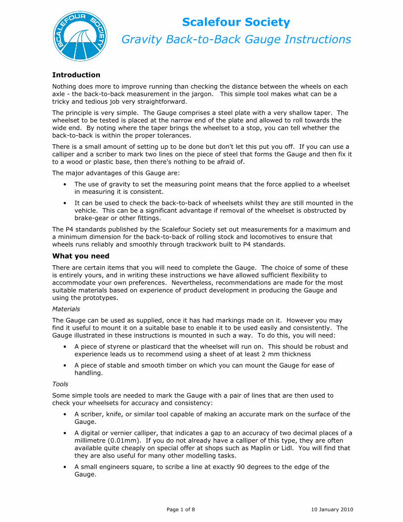
The picture below shows the Gauge as it is supplied from the Stores. Although it is not obvious
in the picture, it tapers from one end to the other, which will be referred to later as the “large”
end and the “small” end. The Gauge is also pre-drilled so that it can be mounted on a board,
and the surface blackened so that it can be marked.
The marks that will be made on the Gauge will be the chosen upper and lower limits that you
wish to use for the back-to-back dimension on your wheels.
The Scalefour Society recommends that for P4 the dimensions are:
• Minimum 17.67 mm
• Maximum 17.75 mm
The first step is to set your calliper to the minimum back-to-back dimension. If your calliper has
a locking nut to set it firmly in place, engage this as it will ensure that you do not accidentally
nudge it out of measurement.

Scalefour Society
Gravity Back-to-Back Gauge Instructions
Page 3 of 8 10 January 2010
The next step is to align the calliper blades on the straight line on your flat surface. You should
insert the small end of the Gauge between the calliper jaws and slowly pull it along between
them until it comes to a natural stop. Do not try and force it through the gap as you do not
want it to become wedged between the jaws.
You then carefully remove the callipers but do NOT move the Gauge. If you do so, then repeat
the exercise. The Gauge will now be positioned with the line on your flat surface in the same
place as the scribed line must be for the minimum back-to-back measurement.
Align your square exactly along the line where the calliper blades were positioned and scribe a single line across the width of the Gauge. This line will be the minimum limit that you wish your
wheels to be set at.

Scalefour Society
Gravity Back-to-Back Gauge Instructions
Page 4 of 8 10 January 2010
Reset your callipers to measure the maximum back-to-back dimension that you are using for
your modelling. Repeat the previous steps to scribe a line that shows this maximum dimension
on the Gauge.
After marking both lines, your Gauge should look like this.
Scalefour Society
Gravity Back-to-Back Gauge Instructions
Page 5 of 8 10 January 2010
Once you have the maximum and minimum limit lines on the Gauge it can be used. However
we recommend mounting it on a base that helps you make consistent and accurate tests.
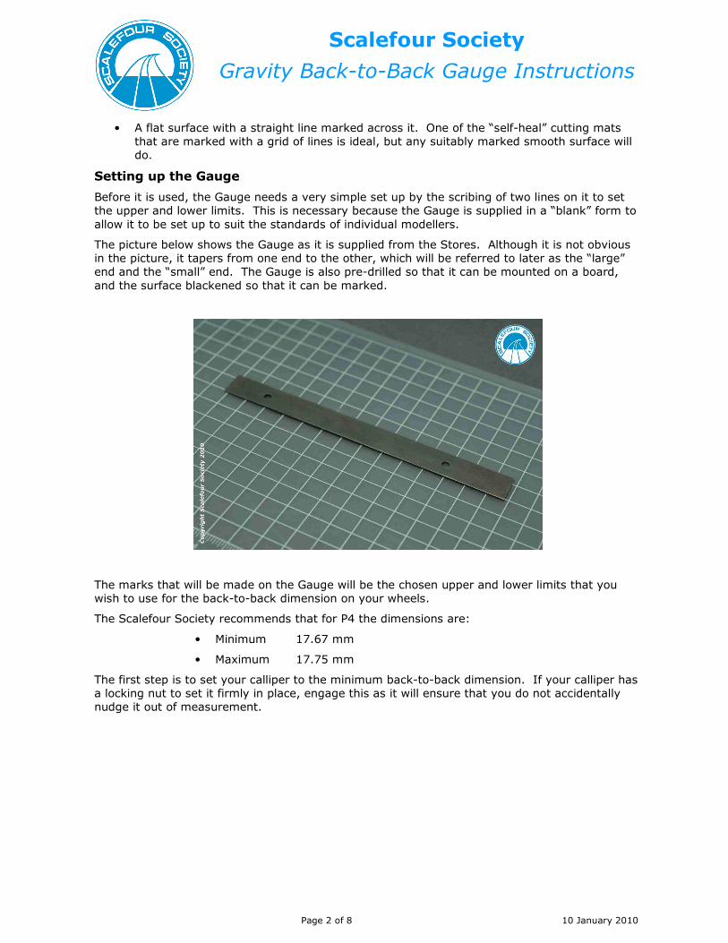
The next picture shows the three main components used to make the base. These are:
• The Gauge, which has already been marked with the measurement lines.
• A piece of smooth styrene or plasticard for the wheelset to run on, of sufficient thickness
that it will be unaffected by use or age.
• A piece of planed or smooth-finished timber to securely mount these items on, and to
provide a robust base for handling the completed Gauge.
The precise measurements of the two supporting pieces are not critical. However we
recommend that it is long enough to support the outermost axle of your longest piece of rolling
stock if you are checking wheelsets mounted in vehicles.
The three components are shown as individual items. The parts can be glued together or
screwed together using suitable fixings. The Gauge is supplied pre-drilled for ease of assembly
by screws, and the pictures of the completed Gauge that follow use pan-head screws as fixings.
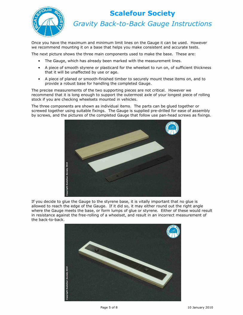
If you decide to glue the Gauge to the styrene base, it is vitally important that no glue is
allowed to reach the edge of the Gauge. If it did so, it may either round out the right angle
where the Gauge meets the base, or form lumps of glue or styrene. Either of these would result
in resistance against the free-rolling of a wheelset, and result in an incorrect measurement of
the back-to-back.

Scalefour Society
Gravity Back-to-Back Gauge Instructions
Page 6 of 8 10 January 2010
The previous picture shows how the finished Gauge may look. Note the scribed lines indicating
the area in which the check will be made.
One final thought on setting the Gauge up: if you slip with your scriber, or mis-measure with the
callipers, and don’t quite get the markings as accurate as you would like, you can always turn
the Gauge over and have a second attempt on the other side. No one apart from you will ever
know.
Using the Gauge
Before using the gauge, it is worth checking the wheelsets visually to ensure that there are no
manufacturing defects or other damage that may affect the measurement.
The left hand wheel has a machining fault that has left an uneven ridge on the back of the tyre.
This would cause a back-to-back setting to be incorrectly offset in relation to the tip of the
flange. This sort of fault cannot be corrected and the wheel should be returned.
The right hand wheel has a piece of swarf from a moulding pip that could give an inaccurate reading if it is caught whilst setting or checking the back-to-back.
To use the Gauge, place the wheelset or vehicle to be checked on the small end. Use a piece of
styrene or card under the small end of the Gauge to create a gentle slope. Push the piece
further toward the centre of the Gauge to increase the slope angle. When the wheelset rolls
down the slope, note where it stops.

Scalefour Society
Gravity Back-to-Back Gauge Instructions
Page 7 of 8 10 January 2010
.

Scalefour Society
Gravity Back-to-Back Gauge Instructions
Page 8 of 8 10 January 2010
Wheel wobble detector
The gauge can also detect wheel wobble, another potential cause of poor running. Run a
wheelset down the gauge several times. If it stops in a different place each time, the wheels are not square on the axle.