Embed Size (px)
Citation preview

1
Grate Boilers in CHP
- are increasing their Competiveness
By
Flemming Skovgaard Nielsen
Nils Peter Astrupgaard
Power-Gen Europe 2015, Amsterdam,
Holland
Tel: +45 3945 2000
www.bwe.dk

2
1. Abstract
Straw fired plants are gaining momentum as a reliable, efficient and environmentally
acceptable power generation technology. This move is supported by the fact that 40% of
EU 27 available biomass resources for energy constitute straw.
Sustainable fuels that can lead to immediate savings of CO2 emissions are primarily
constituted of agrofuels having a one year carbon cycle. Hence the carbon footprint of
plants able to use these difficult and slagging fuels is very low.
BWE engineers has since the 80’ties developed and delivered straw based boiler islands
and the last generation of proven design 120 MWth boilers having steam data of up to 140
bar, 540°C providing electric efficiencies at up to 34 - 36%.
The development stages are supported by the reliability shown from the previous plants
featuring slagging austenitic superheaters – some operated for more than 15 years of
continuous operation without major repair or exchange of these adding to low operational
(OPEX) costs for such difficult fuels.
In the recent years BWE has delivered straw fired Boiler Islands in Germany and the UK
and recently won a contract for the largest straw based CHP boiler island in Denmark. It
also features flue gas condensing in combination with combustion air humidification to
improve the energy efficiency. The latter has never before been demonstrated on a straw
fired plant.
2. Technology Development Since the first straw fired BWE engineered unit commissioned in 1989 at Rudkøbing a
couple of design choises has been followed and refined to outmost success.
Important choises were:
1. Adaptation of the water cooled vibrations grate as part of the high pressure boiler
system
2. A fuel handling system based on rectangular straw bales
3. Additional handling of auxillary fuels such as wood chips at feed rates up to 50%
4. Hanging slagging austenitic superheaters capable of high superheater
temperatures.
5. Modular designs
6. Drum type boiler

3
The design has been improved over the years:
1. Increasing the boiler pressure and temperature
2. Improving the fuel handling and scarifying of the straw bales.
3. Simplification of grate design
4. De NOx technologies from SNCR to SCR
5. Air humidification and succeeding higher heat outputfrom flue gas condensing
systems in CHP mode
The below figure graphically shows the changes of commissioned plants.
The recent design range is represented through the commissioned Emlichheim and
Sleaford boilers that also highlight the modular plant design. Emlichheim is a straw bale
fed boiler plant with two fuel feeding lines and Sleaford has four fuel feeding lines and
additional wood chips feeding into every stoker line.
Generally the combustion system can be supplied with equipment for the handling of
auxiliary fuels such as wood chips or similar fuels with a feed rate of up to 50%. BWE
employs engineers who have designed such plants since the end of the 1980’s.

4
3. Overall Plant Designs The boilers are standing boilers with natural circulation. They have three passes plus
one/one-half or two towers with an economiser and a flue gas cooler. Dry sorbent acid
abatement techniques are employed, as Ca(OH)2 is injected in the flue gas pass before
the fly ash fabric filter. Additionally activated carbon can be injected as well in order to
reduce harmful emissions by chemical means.
Besides generating power, the plants can operate in CHP mode and deliver steam to
nearby process plants and/or heat to a district heating system.
As an important part of a heat supply system, a large accumulator tank is normally
implemented to deal with fluctuations in heat supply/demand.
Plant overview, from BWE 3D (PDMS) model.

5
Emlichheim Main Data
Plant Owner: BEKW Bioenergiekraftwerk Emsland, GERMANY
Year of commissioning: 2012
Fuel: Straw bales
Unmanned operation: Up to 72 hours (possible)
Steam: 18.6 kg/s (522° C, 112 bar)
Efficiency: 92,0%
Capacity: 49.9 MJ/s (thermal input)
From straw to power, processing of steam and heat. (Illustration owned by BEKW)
This illustration shows the main mass and energy balance of the plant. (Illustration owned by BEKW)

6
Sleaford Main Data
Plant Owner: GlennmontPartners
Year of commissioning: 2014
Fuel: Straw bales and wood chips
Unmanned operation: Up to 72 hours (possible)
34%
Steam: 18.6 kg/s (522° C, 112 bar)
Boiler Efficiency: 92,3%
Capacities: 115 MJ/s (thermal input), 38,5 MWe – Net efficiency 34%
The Sleaford straw-fired boiler - sectional view, 115 MWth
7
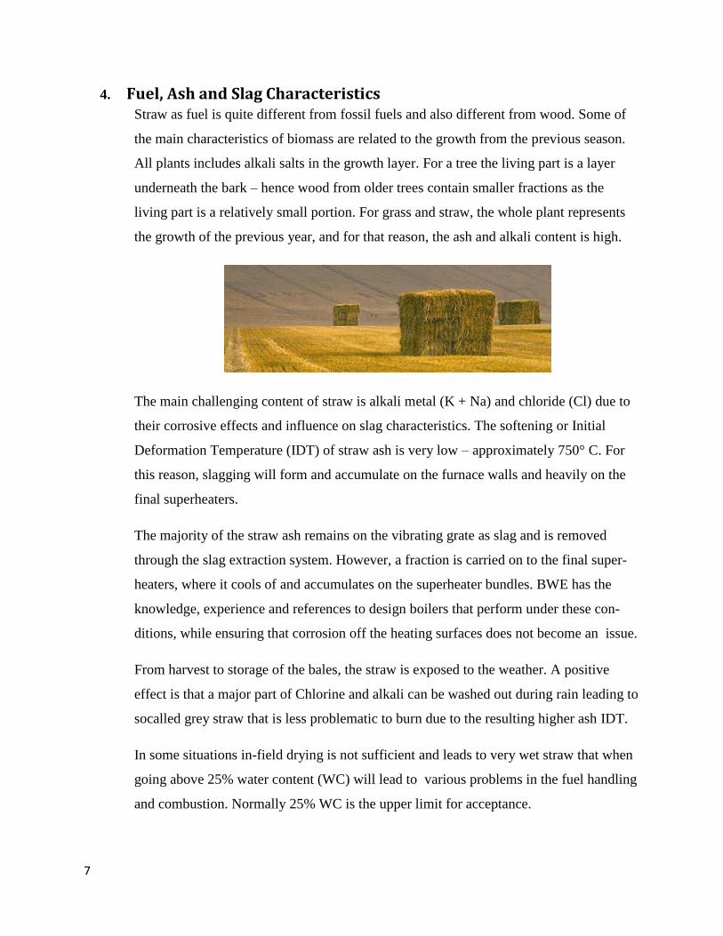
4. Fuel, Ash and Slag Characteristics Straw as fuel is quite different from fossil fuels and also different from wood. Some of
the main characteristics of biomass are related to the growth from the previous season.
All plants includes alkali salts in the growth layer. For a tree the living part is a layer
underneath the bark – hence wood from older trees contain smaller fractions as the
living part is a relatively small portion. For grass and straw, the whole plant represents
the growth of the previous year, and for that reason, the ash and alkali content is high.
The main challenging content of straw is alkali metal (K + Na) and chloride (Cl) due to
their corrosive effects and influence on slag characteristics. The softening or Initial
Deformation Temperature (IDT) of straw ash is very low – approximately 750° C. For
this reason, slagging will form and accumulate on the furnace walls and heavily on the
final superheaters.
The majority of the straw ash remains on the vibrating grate as slag and is removed
through the slag extraction system. However, a fraction is carried on to the final super-
heaters, where it cools of and accumulates on the superheater bundles. BWE has the
knowledge, experience and references to design boilers that perform under these con-
ditions, while ensuring that corrosion off the heating surfaces does not become an issue.
From harvest to storage of the bales, the straw is exposed to the weather. A positive
effect is that a major part of Chlorine and alkali can be washed out during rain leading to
socalled grey straw that is less problematic to burn due to the resulting higher ash IDT.
In some situations in-field drying is not sufficient and leads to very wet straw that when
going above 25% water content (WC) will lead to various problems in the fuel handling
and combustion. Normally 25% WC is the upper limit for acceptance.

8
To motivate the farmer to deliver driest possible straw the payment is normally based on
WC – the lower WC - the higher the payment.
5. From Straw Barn to Stoker The complete bale feeding and handling system is based on BWE’s in-house design of
the equipment. All conveyors are designed with heavy conveyor chains and engagement
spikes.
Before entering the final straw conveyor line to the boiler the bales each pass a weighing
table that can determine the bale mass to within 5 kg. An integrated micro wave
humidity sensor system determines the humidity in the bale, and photo sensors
determine the length of the bales. In this way important information of the bale energy
content is logged. The system keeps track of the bale, and the dosing will be adjusted
with respect to the actual bale and the boiler load needed, thereby optimizing the firing
sequence.
As a means of minimising the “false” air ingress and to prevent a possible fire from
spreading to the straw barn, the straw conveyer lines are isolated by two seal gates. One
bale at a time will pass this sluice.
Yellow straw Grey straw
Unit Very little exposure littleless moisture rain
After 50-150 mm rain
Typical bale density
kg/m³ 200
Typical bale size m 1.2 x 1.2 x 2.5
Humidity, nom. % 10-20
Humidity, max. % 25
Typical LCV MJ/kg 15 (@ 15% humidity)
Ash content % 4 * 3 *
Chloride % 0.6 0.2
Alkali in ash % 30 10-20
Ash IDT °C 750 1000
Price level Euro/GJ 4.5 4.5
* Cereal. For corn stover, sorghum and miscanthus, values can be up to 7%

9
On the left: Heavy and stabilising counter rotating synchronising cog wheels. On the right: Straw bale inlet and heavy impellers for straw bale disintegration.
The conveyor is equipped with a variable speed drive to deliver the feeding required and
calculated, on the basis of the bale characteristics.
Just before a bale enters the straw divider, a string cutter cuts the twines holding the bale
together. The straw divider consists of two counter rotating, impeller-like wheels which
“scrape” off the straw layers of the bales to fall down in the straw chute. The straw
divider is a heavy duty patented BWE design.
The straw chute is equipped with a fast closing damper that in different situations can
provide a sealing against “false” air ingress and also offer protection against back fire.
The loose straw falls down the chute and arrives on top of the double stoker screw. The
stoker has two opposite rotating conical and progressive screws. The screws ensure that
Straw conveyor lines.
On the left: the two seal
gates.
On the right: the canopy for
the spike wheel, cabinets for
the down force dollies and
the string cutter.

10
the straw and strings will be transported and pressed forward forming a practically air
tight plug through the water-cooled stoker duct.
6. The water-cooled Vibration Grate The water-cooled vibration grate offers very low maintenance costs and provides high
availability and extremely low power consumption as the vibration drive only operates
1—2% of the time and with a moderate installed power of 22 kW for the drive motor.
The grate is a part of the evaporator system ensuring problem-free start-ups and high
boiler efficiency.
The main characteristics of the water-cooled vibration grate are as follows:
One commonly controlled primary air box;
Two – to four parallel grate sections with balanced operation;
Each section has a membrane wall with holes in the fins for primary air;
Flex tubes between grate headers and boiler connection points for absorption of
dynamic movements;
Flexible joints, performing air tightening between the grate, the boiler and
surroundings;
Air tightening plates performing sealings along the grate; and
Spring-supported material and an air seal between the grate sections.
This illustration shows the
vibration grate and its
surroundings. The orange
line indicates the surface of
the straw. Notice the
individual slag hoppers for
1st, 2nd and 3rd boiler pass to
a common slag conveyor.

11
The grate is inclined at a low angle, still allowing it to be a part of the evaporator system
without the risk of steam stagnation and thereby an overheating of the membrane. The
vibration drive is operating intermittently; typically, with one vibration sequence every
two to five minutes. The vibration ensures a mixing of fresh and already ignited fuel. In
addition, the vibration generates transport down the grate from the reception/heating-
/drying zones to the area where the main combustion takes place, further down to the
zone where the coke glows out, and finally to the cooling zone for the ashes before
falling into the slag hopper.
The primary air is distributed through a predesigned hole pattern in the grate surface –
the membrane which is the water-cooled part of the grate. Many factors are important to
obtain stable and well-controlled combustion. The vibration grate must have effective air
tightening so that the combustion air leakage at the corners and joints are low. The air
flow from the air box to the grate surface must be properly designed and controlled I
norder that the main zones are fed with the optimal air flow for the drying zone, the
combustion zone and the burn-out zone.
The grate surface is split into two to four opposite moving membrane sections supported
by grate carriers and blade springs which allow the dynamic movement in the vibration
sequence.
The grate is exposed to all of the traditional conditions caused by mechanical stress,
wear and tear:
Thermal expansion and loads;
Dynamic movements and loads;
Self-oscillation (avoided by design);
Wear and tear from the abrasive ash and slag and the fuel itself;
Air tightening; and
Local high heat input.
To control all these issues, many special designs have been applied.

12
7. Boiler and Superheater The boiler design is dedicated to straw firing. The large noses in the furnace for air
nozzles and acceleration of the combustible gasses are very important features. The
boiler is standing on the sidewall bottom headers on feets with defined friction and
guides.
In order to obtain reasonable low air excess and also to keep UBC, CO and NOx low,
the right distribution of combustion air is important. Primary air is introduced through
the holes in the grate surface. The rest of the combustion air is introduced through a
number of air injection nozzles in connection to the furnace noses. With optimised
operation, the air excess will be 1.30 – a fine result, taking the fuel characteristics and
firing technique into account – but, of course, not on the same level as a modern, large
utility boiler (λ1.15-1.17)
Due to the extreme tendency to build up slags, the two final superheaters in the furnace
and 2nd
pass are of the hanging or “platen” type with a large pitch. The final superheaters
are made of austenitic steel which, to a large degree is resistant to the corrosive salts.
The design is based on “balanced slagging” which means that heat balances are based on
a certain build up of slag.
The slags will build up to a layer where
the surface temperature is equal to the
melting temperature of the slag that
constantly drips off the SH surfaces. The
large pitch still allows for sufficiently free
space for the flue gasses.
This illustration shows a “cold view”
view of balanced slagging – where
the full layer of slag is reached.
Slags are dripping from the
superheaters in normal operation.

13
Control of steam outlet data is a challenge . Heat absorbed in the furnace is highly
affected by the slag layer and the actual heat release in the furnace. To reduce the slag
layer influence, water cannons operate with various programmes to clean the furnace
walls thereby controlling the heat absorption in the furnace walls. At the same time,
variations in heat input due to variations in straw flow and energy content require
effective means for control, which is done by various attemperator after the different
superheater segments.
Reliability and a long lifetime are ensured by numerous initiatives. In relation to the
design data, the grate membrane is designed with elevated material grades and an
additional wall thicknesses.
The final superheaters are, as mentioned earlier, designed with high grade boiler
austenitic stainless steel. For this purpose, BWE uses TP 347 H, which is proven through
more than 20 years of operation in plants designed by us.
8. Advances in Boiler Performance With respect to optimization of electric efficiency the laws of Carnot must be obeyed.
When it comes to boilers this is mainly done by securing extreme pressures and
superheater temperatures and if possible - application of steam reheat to obtain highest
mean steam temperature for the cycle.
The availability of adequate steam turbines is also a limiting factor as well as a their
demand for a reasonable high mass flow to safeguard low turbine inlet losses. For the
larger biomass boilers providing around 40 MWe turbine suppliers can offer steam
turbines with reheat options.
BWE is in progress with designing such a boiler – also for straw. This involves a highly
experienced engineering staff that based on the knowledge from several advanced straw
fired steam boilers can provide a design for a boiler with a heat flux that over time varies
a lot due to different slag build ups etc. Such a boiler based on steam data of 140 bar and
540 ˚C promises more than 35% net electric efficiency and net electric yields between
40 and 50 MWe.

14
9. Advances in CHP and Environmental Performance Many customers have focus on the ability to supply heat and power with special
attention on high heat performance. Flue gas condensing can help fulfilling this demand.
For a relatively dry fuel as straw this can be rather difficult.
To overcome this barrier air humidification of the combustion air raises the relative
humidity of the flue gas elevating the condensing temperature and hence the amount of
heat that can be delivered. At the same time it supercools the flue gas. It can be
recognized as a kind of thermal heat pump.
BWE is delivering a straw fired boiler to the city of Aarhus/Denmark supplied with
exactly this type of combustion air humidification and condensing bringing the boiler
over all efficiency up to approximately 103% with respect to lower heating value (LHV).
The flue gas system in this system consists of the following packages:
1. Reagent storage and injection system
2. Fabric filter
3. SCR catalyst
4. Combustion air humidifier
5. Flue gas quencher and condenser
6. Chemical storage and dosing system
7. Waste water treatment
Below the full system is depicted.

15
In the below figure the condensing/air humidification system can be seen in detail.
10. Results of Advances in CHP The table below shows how a boiler in CHP mode can be optimized using the previously
described air humidification and condensing technologies. The 110 MWth Lisbjerg**
CHP performance is modelled in different optimization stages. It is compared to the
117 MWth Sleaford* power plant. Both plants share the same boiler values of 110 bar
and 540 ˚C superheated steam temperature.
Heat input
Flue gas conden-
sing
Comb. air
humidi-fication
Gross electrical
output
Auxiliary consump-
tion
Net power output
Electri-cal effi-ciency
District heating Steam MJ/s
Flue gas dew point
Flue gas temperature
District heating Flue gas
1)
Fuel effi-ciency (LHV)
MWth
MWe MWe MWe % MJ/s °C °C MJ/s %
117* No No
38,5 34 0 - 130 0
110** No No 38 2,46 35,4 32,2 66,2 52,4 113 1,5 94.2
110** Yes No 37,4 2,68 34,5 31,4 65,1 52,8 46 1.5+7,5 99,4
110** Yes Yes 37,2 2,84 34,3 31,2 64,9 59,7 40
(reheated) 1,3+12,
3 103,3

16
It can be seen that the Sleaford power plant has an electric net electric efficiency of 34%.
The Lisbjerg CHP plant has a slightly lower net electric efficiency of 32,2% due to a
minor loss of electricity production in order to produce heat. In return the fuel efficiency
is increased from 34% to 94,2%. In steps first flue gas condensing and subsequently
combustion air humidification measures are implemented. At a loss of only 1% percent
point of the net electric efficiency a gain in more than 9 percent point of heat is realized.
11. Advances in Environmental Performance In this section the environmental performance of the previously in section 9 discussed
developments are described for the straw fired power plants. They are compared to the
draft coming BAT references for Large Combustion Plants (LCP).
The figures are based on EN 14961 for straw firing at moisture content less than 25%
and relate to emissions in mg/Nm3 at 6% O2 dry. Indices 1) and 2) refer to Sleaford(117
MWth)/Brigg(120 MWth) plants and Snetterton(130 MWth) plant respectively. The figures
in these two rows are guarantee values as well as the Lisbjerg row.
The environmental performance has improved considerably over a span of just 5 years.
The Lisbjerg plant already is in compliance with the future expected criteria for LCP
BREF – although the guarantee values for acid components are slightly higher.
* * *
NOx SOx HCl NH3 CO Particulate
LCP BREF DRAFT >100 MWth (April 2015) 50-140 10-50 0,3-5 5-10 15-160 2-5
Boiler with bag filter 320 n.a. <100 <5
Boiler with SNCR, dry sorbent injection and bag filter 1) 200-250 50-200 10-25 10-12 <100 <10
Boiler with dry sorbent injection, bag filter, tail end SCR 2) <40 50-200 <10 <5 <100 <10
Boiler with dry sorbent injection, bag filter, tail end SCR
and flue gas condensing
<40 <50 <5 <5 <100 <5
Lisbjerg DK guarantees <40 <60 <10 <5 n.a. <4


![[Global HR Forum 2011] Creation of A New Corporate Competiveness: Social Marketing and Utilizing Human Resources](https://img.dokumen.tips/doc/110x75/5590df121a28ab39578b46f2/global-hr-forum-2011-creation-of-a-new-corporate-competiveness-social-marketing-and-utilizing-human-resources.jpg)