Embed Size (px)
Citation preview
Grass Trimmer/Brush CutterOperator's Manual
MODELS, SRM - 261SRM - 261SSerial Number 002001001 & Up
WARNING DANGERRead rules for safe operation and instructions carefully. ECHO provides anOperator's Manual and a Safety Manual. Both must be read and understood forproper and safe operation. Failure to do so could result in serous injury.
X7502094301 X75000118106/01
2
INTRODUCTION
Welcome to the ECHO family. This ECHO product was designed and manufactured to provide long life and on-the-job-dependability. Read and understand this manual and the SAFETY MANUAL you found in the same package. Youwill find both easy to use and full of helpful operating tips and SAFETY messages.
THE OPERATOR'S MANUAL —Contains specifications and information for operation, starting,stopping, maintenance, storage and assembly specific to this product.
THE SAFETY MANUAL —Explains possible hazards involved with the use of Grass Trimmers andBrush Cutters and the proper trimming techniques you should use forsafe operation.
TABLE OF CONTENTS
Introduction ........................................................................ 2- The Operator's Manual .............................................. 2- The Safety manual ...................................................... 2
Manual Safety Symbols and Important Information ......... 3Safety .................................................................................. 3
- Decals ......................................................................... 3- International Symbols ................................................. 4
Safety Instructions ............................................................. 5- Personal Condition and Safety Equipment ................. 5- Extended Operation/Extreme Conditions ................... 5- Equipment .................................................................. 6- Safe Operation ............................................................ 7
Emission Control ................................................................ 7Description ......................................................................... 8
- Contents ..................................................................... 8Assembly .......................................................................... 10
- Specifications ............................................................ 10- Plastic Shield Installation .......................................... 11- Nylon Head Installation ........................................... 11- Front Handle Installation .......................................... 11- Operation with Blades .............................................. 12- Harness Clamp Installation ...................................... 13- Metal Shield Installation ........................................... 14- U-Handle Installation ............................................... 15
Pre-Operation ................................................................... 17- Fuel ........................................................................... 17
Operation .......................................................................... 18- Starting Cold Engine ................................................. 18
- Starting Warm Engine ............................................... 19- Stopping Engine ........................................................ 19
Maintenance ..................................................................... 20- Skill Levels ................................................................ 20- Maintenance Intervals .............................................. 20- Air Filter ................................................................... 21- Fuel Filter ................................................................. 21- Spark Plug ................................................................. 22- Cooling System Cleaning .......................................... 22- Exhaust System ........................................................ 23- Carburetor Adjustment ............................................. 24- Lubrication ................................................................ 25- Nylon Line Replacement .......................................... 26- Sharpening Metal Blades .......................................... 27
Troubleshooting ................................................................ 28Storage .............................................................................. 29Servicing Information ........................................................ 32
- Parts .......................................................................... 32- Service ....................................................................... 32- ECHO Consumer Product Support .......................... 32- Warranty Card .......................................................... 32- Additional or Replacement Manuals ........................ 32
Specifications, descriptions and illustrative material inthis literature are as accurate as known at the time ofpublication, but are subject to change without notice.Illustrations may include optional equipment andaccessories, and may not include all standard equipment.
CopyRight© 2001 By Echo, IncorporatedAll Rights Reserved.
GRASS TRIMMER/BRUSH CUTTEROPERATOR'S MANUAL 3
This symbol accompanied by the words WARNING andDANGER calls attention to an act or condition that can lead toserious personal injury to operator and bystanders.
The circle with the slash symbol means whatever is shownwithin the circle is prohibited.
MANUAL SAFETY SYMBOLS AND IMPORTANT INFORMATION
IMPORTANT The enclosed messageprovides information necessary for theprotection of the unit.
NOTE This enclosed message provides tips foruse, care and maintenance of the unit.
Throughout this manual and on the product itself, you will find safetyalerts and helpful, information messages preceded by symbols or keywords. The following is an explanation of those symbols and keywords and what they mean to you.
SAFETY
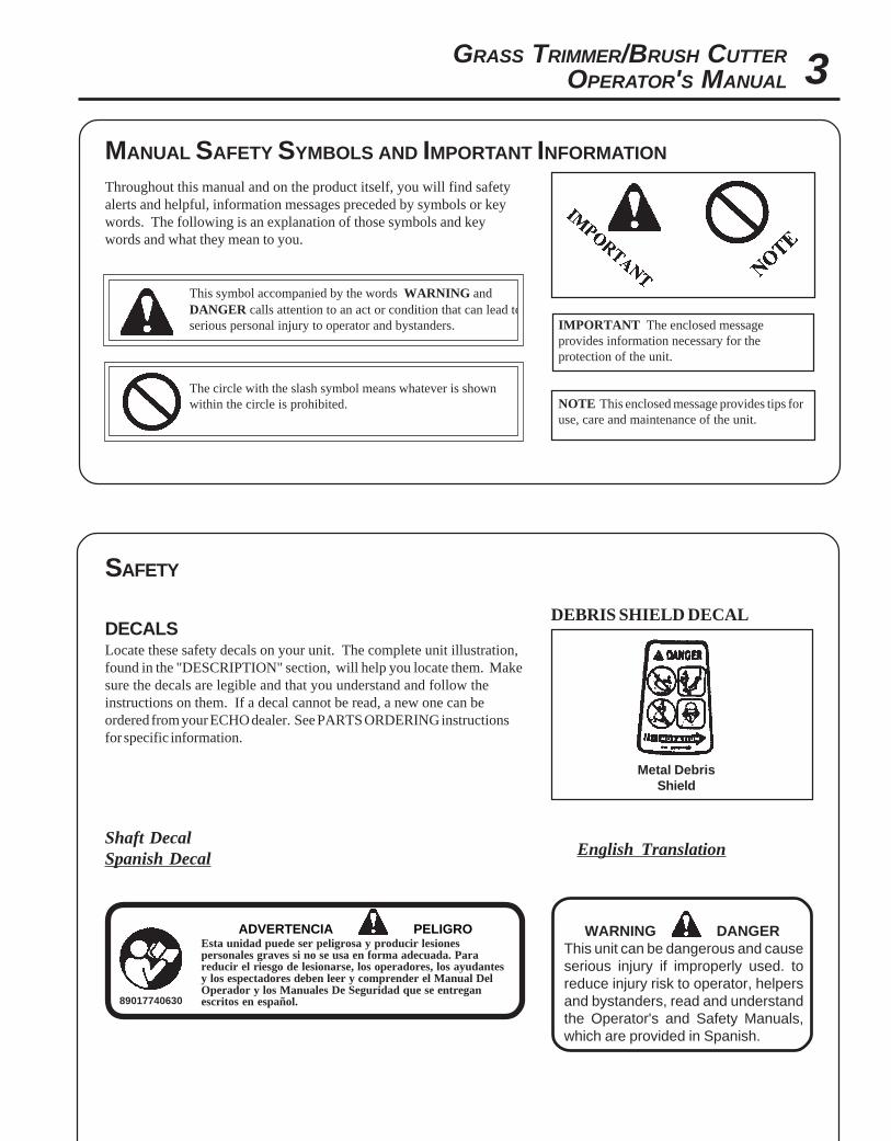
DECALSLocate these safety decals on your unit. The complete unit illustration,found in the "DESCRIPTION" section, will help you locate them. Makesure the decals are legible and that you understand and follow theinstructions on them. If a decal cannot be read, a new one can beordered from your ECHO dealer. See PARTS ORDERING instructionsfor specific information.
WARNING DANGERThis unit can be dangerous and causeserious injury if improperly used. toreduce injury risk to operator, helpersand bystanders, read and understandthe Operator's and Safety Manuals,which are provided in Spanish.
ADVERTENCIA PELIGROEsta unidad puede ser peligrosa y producir lesionespersonales graves si no se usa en forma adecuada. Parareducir el riesgo de lesionarse, los operadores, los ayudantesy los espectadores deben leer y comprender el Manual DelOperador y los Manuales De Seguridad que se entreganescritos en español.89017740630
Shaft DecalSpanish Decal English Translation
DEBRIS SHIELD DECAL
Metal DebrisShield

4
Shaft Decal
WARNING DANGER
• This unit can be dangerous and cause serious injury if improperly used. Toreduce injury risk to operator, helpers and bystanders, read and understandthe Operator's and Safety manuals.
• Blindness can occur from objects that are thrown or ricocheted even withshield in place. Operators, helpers and bystanders must wear ANSI Z87.1approved eye protection.
• Always wear hearing protection when operating unit.• Prevent accidental contact with unit and any cutting attachment. Maintain a
15M (50 ft.) radius, DANGER ZONE surrounding the operator. ONLY theoperator, dressed in proper protective clothing should be in the DANGERZONE.
• Beware of KICKOUT (blade thrust) when using blades. Special precau-tions are necessary for blade operation, see your Operator's and SafetyManuals. ONLY install ECHO approved blades on Brush Cutters (SRM)models equipped with proper blade shield, U-handles, harness, blade collar,nut and cotter pin.
• Blade/Cutting attachment does not stop immediately after releasingthrottle.Keep hands and feet clear of blade/cutting attachment unless engine is shutoff and cutting attachment is not moving.
• INSPECT BLADES BEFORE USE.• DO NOT USE DAMAGED, CRACKED, BENT, DULL OR IMPROP-
ERLY SHARPENED BLADES.• Do not remove shields, modify the unit or install attachments or parts not
approved by ECHO. Approved attachment information and replacementOperator's and Safety Manuals are available from your ECHO dealer or bywriting: ECHO, INCORPORATED, 400 OAKWOOD RD., LAKEZURICH, IL 60049.
P/N 89016844830
INTERNATIONAL SYMBOLS
Symboldescription/application Symbol form/shape Symbol
description/applicationSymbol form/shape
HotSurface
Carburetor adjustment- Idle speed
Carburetor adjustment- High speed mixture
Symboldescription/application Symbol form/shape
Symboldescription/applicationSymbol form/shape
"WARNING, SEEOPERATOR'S
MANUAL
Wear eyes, ears andhead protection
Emergency stopFuel and oil mixture
Finger Severing
Carburetor adjustment- Low speed mixture
Primer Bulb
IgnitionON/OFF
Wear hand andfoot protection
Safety/Alert
Keep bystanders and helpersaway 15 m (50 ft.).
DO NOT smokenear fuel.
DO NOT allowflames or sparks
near fuel.
Engine chokecontrol.
GRASS TRIMMER/BRUSH CUTTEROPERATOR'S MANUAL 5
WARNING DANGERTrimmer/Brush Cutter users risk injury to themselves and others if the trimmer/brush cutter is used improperly and orsafety precautions are not followed. Proper clothing and safety gear must be worn when operating a trimmer.
SAFETY INSTRUCTIONSPERSONAL CONDITION AND SAFETY EQUIPMENT
EXTENDED OPERATION/EXTREME CONDITIONS
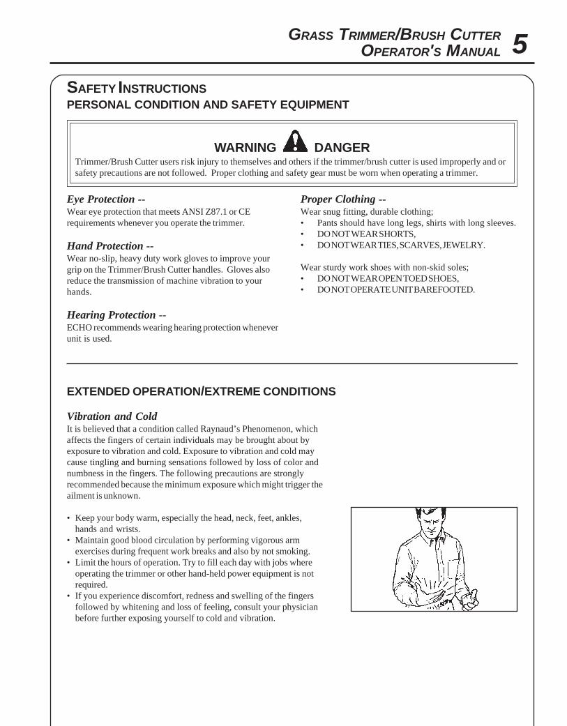
Vibration and ColdIt is believed that a condition called Raynaud’s Phenomenon, whichaffects the fingers of certain individuals may be brought about byexposure to vibration and cold. Exposure to vibration and cold maycause tingling and burning sensations followed by loss of color andnumbness in the fingers. The following precautions are stronglyrecommended because the minimum exposure which might trigger theailment is unknown.
• Keep your body warm, especially the head, neck, feet, ankles,hands and wrists.
• Maintain good blood circulation by performing vigorous armexercises during frequent work breaks and also by not smoking.
• Limit the hours of operation. Try to fill each day with jobs whereoperating the trimmer or other hand-held power equipment is notrequired.
• If you experience discomfort, redness and swelling of the fingersfollowed by whitening and loss of feeling, consult your physicianbefore further exposing yourself to cold and vibration.
Eye Protection --Wear eye protection that meets ANSI Z87.1 or CErequirements whenever you operate the trimmer.
Hand Protection --Wear no-slip, heavy duty work gloves to improve yourgrip on the Trimmer/Brush Cutter handles. Gloves alsoreduce the transmission of machine vibration to yourhands.
Hearing Protection --ECHO recommends wearing hearing protection wheneverunit is used.
Proper Clothing --Wear snug fitting, durable clothing;• Pants should have long legs, shirts with long sleeves.• DO NOT WEAR SHORTS,• DO NOT WEAR TIES, SCARVES, JEWELRY.
Wear sturdy work shoes with non-skid soles;• DO NOT WEAR OPEN TOED SHOES,• DO NOT OPERATE UNIT BAREFOOTED.
6
• Check unit for loose/missing nuts, bolts and screws. Tighten and/orreplace as needed.
• Inspect fuel lines, tank and area around carburetor for fuel leaks. DONOT operate unit if leaks are found.
• Inspect shield for damage and ensure that the cut-off knife issecurelyin place. Replace if either is damaged or missing.
• Check that the cutting attachment is firmly attached and in safeoperating condition.
• Check that front (loop) handle and optional shoulder/waist harnessare adjusted for safe, comfortable operation. See Assembly for properadjustment.
• Keep exhaust area clear of flammable debris. Avoid contact duringand immediately after operation.
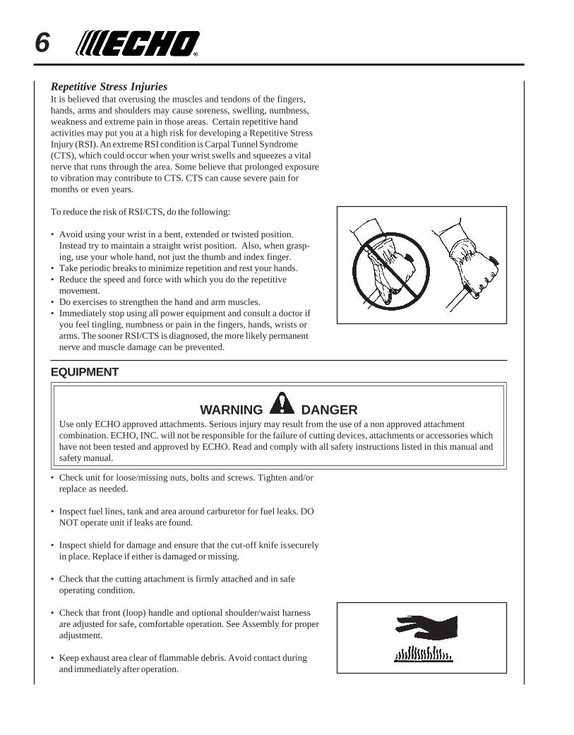
Repetitive Stress InjuriesIt is believed that overusing the muscles and tendons of the fingers,hands, arms and shoulders may cause soreness, swelling, numbness,weakness and extreme pain in those areas. Certain repetitive handactivities may put you at a high risk for developing a Repetitive StressInjury (RSI). An extreme RSI condition is Carpal Tunnel Syndrome(CTS), which could occur when your wrist swells and squeezes a vitalnerve that runs through the area. Some believe that prolonged exposureto vibration may contribute to CTS. CTS can cause severe pain formonths or even years.
To reduce the risk of RSI/CTS, do the following:
• Avoid using your wrist in a bent, extended or twisted position.Instead try to maintain a straight wrist position. Also, when grasp-ing, use your whole hand, not just the thumb and index finger.
• Take periodic breaks to minimize repetition and rest your hands.• Reduce the speed and force with which you do the repetitive
movement.• Do exercises to strengthen the hand and arm muscles.• Immediately stop using all power equipment and consult a doctor if
you feel tingling, numbness or pain in the fingers, hands, wrists orarms. The sooner RSI/CTS is diagnosed, the more likely permanentnerve and muscle damage can be prevented.
EQUIPMENT
WARNING DANGERUse only ECHO approved attachments. Serious injury may result from the use of a non approved attachmentcombination. ECHO, INC. will not be responsible for the failure of cutting devices, attachments or accessories whichhave not been tested and approved by ECHO. Read and comply with all safety instructions listed in this manual andsafety manual.

GRASS TRIMMER/BRUSH CUTTEROPERATOR'S MANUAL 7
SAFE OPERATION
WARNING DANGERDo not operate this product indoors or in inadequately ventilatedareas. Engine exhaust contains poisonous emissions and can causeserious injury or death.
• Provide all operators of this equipment with the Operator's Manualand instructions for safe operation.
Keep A Firm Grip• Hold the front and rear handles with both hands with thumbs and
fingers encircling the handles
Keep A Solid Stance• Maintain footing and balance at all times. Do not stand on slippery,
uneven or unstable surfaces. Do not work in odd positions or onladders. Do not over reach.
IMPORTANT ENGINE INFORMATIONENGINE FAMILY: YEHXS.0254CA
DISPLACEMENT: 25.4 CC
THIS ENGINE MEETS U.S. EPA PH1 AND 2000 AND
LATER CALIFORNIA EMISSION REGULATIONS FOR
S.O.R.E. REFER TO OWNER'S MANUAL FOR
MAINTENANCE SPECIFICATIONS AND ADJUSTMENTS.
EMISSION CONTROL
California Tier 2The emission control system for these engines are EM (Engine Modifi-cation).
An Emission Control Label is located on the engine. (This is anEXAMPLE ONLY, information on label varies by engine FAMILY).
AIR INDEX TAGThe Air Index Tag indicates, for purposes of consumer awareness, howthis product's emissions compare to the standards enacted by theCalifornia Air Resources Board.
PRODUCT EMISSION DURABILITYThe 300 hour emission durability period is the time span selectedby the manufacturer certifying the engine emissions output meetsapplicable California emissions regulations, provided that ap-proved maintenance procedures are followed as listed in theMaintenance Section of this manual.
8DESCRIPTION
The ECHO product you purchased has been factory pre-assembled for your convenience. Due to packaging restrictions,shield installation and other assembly may be necessary.
After opening the carton, check for damage. Immediately notify your retailer or ECHO Dealer of damaged or missingparts. Use the contents list to check for missing parts.
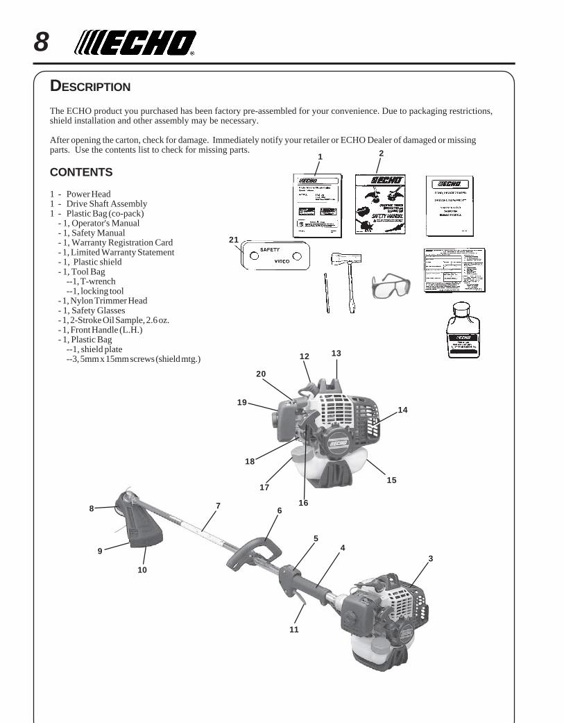
CONTENTS
1 - Power Head1 - Drive Shaft Assembly1 - Plastic Bag (co-pack)
- 1, Operator's Manual- 1, Safety Manual- 1, Warranty Registration Card- 1, Limited Warranty Statement- 1, Plastic shield- 1, Tool Bag
--1, T-wrench--1, locking tool
- 1, Nylon Trimmer Head- 1, Safety Glasses- 1, 2-Stroke Oil Sample, 2.6 oz.- 1, Front Handle (L.H.)- 1, Plastic Bag
--1, shield plate--3, 5mm x 15mm screws (shield mtg.)
34
5
678
9
10
11
1 2
12
14
15
16
17
18
19
20
13
21

GRASS TRIMMER/BRUSH CUTTEROPERATOR'S MANUAL 9
1. OPERATOR'S MANUAL - Included in plastic bag (co-pack). Read before operation and keep in a safe place for
future reference, i.e., operation, maintenance, storage and specifications.
2. SAFETY MANUAL - Included in plastic bag (co-pack). Read before operation and keep in a safe place for future
reference to learn proper, safe operating techniques.
3. POWER HEAD - Includes the Engine, Clutch, Fuel System, Ignition System and Recoil Starter.
4. GRIP - Rear (right hand) handle.
5. STOP SWITCH - "SLIDE SWITCH" mounted on top of the Throttle Trigger Housing. Move switch FORWARD to
RUN, BACK to STOP.
6. FRONT HANDLE - The Front (loop) handle is loosely assembled to the Drive Shaft assembly and must be posi-
tioned for proper cutting attitude and operator comfort.
7. DRIVE SHAFT ASSEMBLY - Includes the Rear (right hand) Handle assembly, Gear Housing assembly, Front (loop,
left hand) Handle assembly, steel drive shaft and Safety Decal.
8. NYLON CUTTER HEAD - Contains replaceable nylon trimming line that advances when the trimmer head is tapped
against the ground while the head is turning at normal operating speed.
9. CUT-OFF KNIFE - Automatically trims line to the correct length: 5" after head is tapped on the ground. If trimmer is
operated without a cut-off knife the line will become too long, the engine will overheat and engine damage may occur.
10. PLASTIC DEBRIS SHIELD ASSEMBLY - Included in plastic bag (co-pack). MUST be installed on unit before use,
see Assembly Instructions. Shield assembly includes the Cut-Off Knife. Mounts on the Gear Housing Assembly just
above the cutting attachment. Helps protect the operator by deflecting debris produced during the trimming opera-
tion. This shield must be replaced with the steel shield for blade use.
11. THROTTLE TRIGGER - Spring loaded to return to idle when released. During acceleration, press trigger gradually
for best operating technique.
12. SPARK PLUG - Provides spark to ignite fuel mixture.
13. ARM REST - Provides arm rest during operation and protects arm from the hot engine.
14. SPARK ARRESTOR - CATALYTIC MUFFLER / MUFFLER -The muffler or catalytic muffler controls exhaust noise
and emission. The spark arrestor screen prevents hot, glowing particles of carbon from leaving the muffler. Keep
exhaust area clear of flammable debris.
15. FUEL TANK - Contains fuel and fuel filter.
16. RECOIL STARTER HANDLE - Pull handle slowly until starter engages, then quickly and firmly. When engine
starts, return handle slowly. DO NOT let handle snap back or damage to unit will occur.
17. FUEL TANK CAP - Covers and seals fuel tank opening.
18. PRIMER BULB - Pumping primer bulb before starting engine draws fresh fuel from the fuel tank priming the carbure-tor for starting. Pump primer bulb until fuel is visible and flows freely in the clear fuel tank return line. Pump bulb anadditional 4 or 5 times.
19. AIR CLEANER - Contains replaceable filter element.
20. CHOKE - The choke control is located on the top of the air filter case. Move choke lever to "Cold Start" to close
choke for cold start. Move choke lever to "Run" position to open choke.
21. SAFETY VIDEO - (Not included with unit) P/N 99922202540 English version only is available at a cost of $5.00 from
ECHO, INC. or any authorized ECHO dealer. The video overviews safety precautions and proper operating tech-
niques and is supplemental to the Safety Manual. Read and understand the Safety Manual for complete information
on safe operation.
10ASSEMBLY
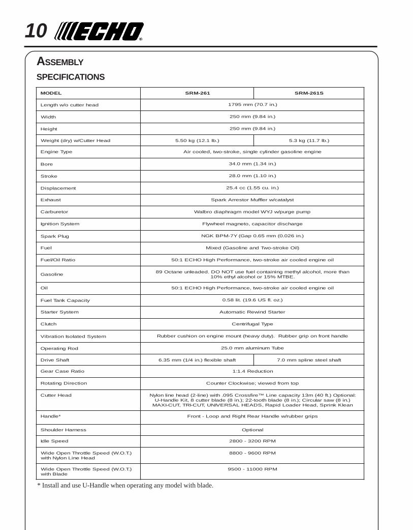
SPECIFICATIONS
* Install and use U-Handle when operating any model with blade.
LEDOM 162-MRS S162-MRS
daehrettuco/whtgneL ).ni7.07(mm5971
htdiW ).ni48.9(mm052
thgieH ).ni48.9(mm052
daeHrettuC/w)yrd(thgieW ).bl1.21(gk05.5 ).bl7.11(gk3.5
epyTenignE enigneenilosagrednilycelgnis,ekorts-owt,deloocriA
eroB ).ni43.1(mm0.43
ekortS ).ni01.1(mm0.82
tnemecalpsiD ).ni.uc55.1(cc4.52
tsuahxE tsylatac/wrelffuMrotserrAkrapS
roterubraC pmupegrup/wJYWledommgarhpaidorblaW
metsySnoitingI egrahcsidroticapac,otengamleehwylF
gulPkrapS ).ni620.0(mm56.0paG(Y7-MPBKGN
leuF )liOekorts-owTdnaenilosaG(dexiM
oitaRliO/leuF lioenignedeloocriaekorts-owt,ecnamrofrePhgiHOHCE1:05
enilosaGnahterom,lohoclalyhtemgniniatnocleufesuTONOD.dedaelnuenatcO98
.EBTM%51rolohoclalyhte%01
liO lioenignedeloocriaekorts-owt,ecnamrofrePhgiHOHCE1:05
yticapaCknaTleuF ).zo.lfSU6.91(.til85.0
metsySretratS retratSdniweRcitamotuA
hctulC epyTlagufirtneC
metsySdetalosInoitarbiV eldnahtnorfnopirgrebbuR.)ytudyvaeh(tnuomenignenonoihsucrebbuR
doRgnitarepO ebuTmunimulamm0.52
tfahSevirD tfahselbixelf).ni4/1(mm53.6 tfahsleetsenilpsmm0.7
oitaResaCraeG noitcudeR4.1:1
noitceriDgnitatoR potmorfdeweiv;esiwkcolCretnuoC
daeHrettuC :lanoitpO).tf04(m31yticapaceniL™erifssorC590.htiw)enil-2(daehenilnolyN).ni8(wasralucriC;).ni8(edalbhtoot-22;).ni8(edalbrettuc8,tiKeldnaH-UnaelKknirpS,daeHredaoLdipaR,SDAEHLASREVINU,TUC-IRT,TUC-IXAM
*eldnaH spirgrebbur/weldnaHraeRthgiRdnapooL-tnorF
ssenraHredluohS lanoitpO
deepSeldI MPR0023-0082
).T.O.W(deepSelttorhTnepOediWdaeHeniLnolyNhtiw
MPR0069-0088
).T.O.W(deepSelttorhTnepOediWedalBhtiw
MPR00011-0059

GRASS TRIMMER/BRUSH CUTTEROPERATOR'S MANUAL 11
PLASTIC SHIELD INSTALLATION(for Nylon Line Operation Only)
Tools Required: Screwdriver.
Parts Required: Plastic Shield, Shield Plate, three (3) 5mm x 15mmscrews.
NOTEFor added comfort, harness kit P/N 99944200200 may be installed foruse with line head and plastic shield. Follow installation instructionsincluded with harness kit.
1. Remove plastic threaded shaft sleeve and adapter plate (A) fromPTO shaft.
2. Place the shield on the bottom of the bearing housing flange.
3. Place shield plate (B) on shield, align holes. Install three (3) screwsfrom bottom through plate and shield into gear case.
4. Assemble adapter plate (A) onto PTO shaft.
NYLON LINE HEAD INSTALLATION
Tools Required: Head Locking Tool,
Parts Required: Nylon Line Head.
1. Be sure adapter plate (A) remains on PTO shaft.
2. Align locking hole in upper plate with notch in edge of gearhousing and insert head locking tool (C).
3. Thread line head onto shaft by turning it counter clockwise untilhead is tight against adapter plate (A).
FRONT HANDLE INSTALLATION
Tools Required: Screwdriver.
Parts Required: Front Handle Assembly
1. Position front handle for comfortable operation and secure screws.
AB
C
12
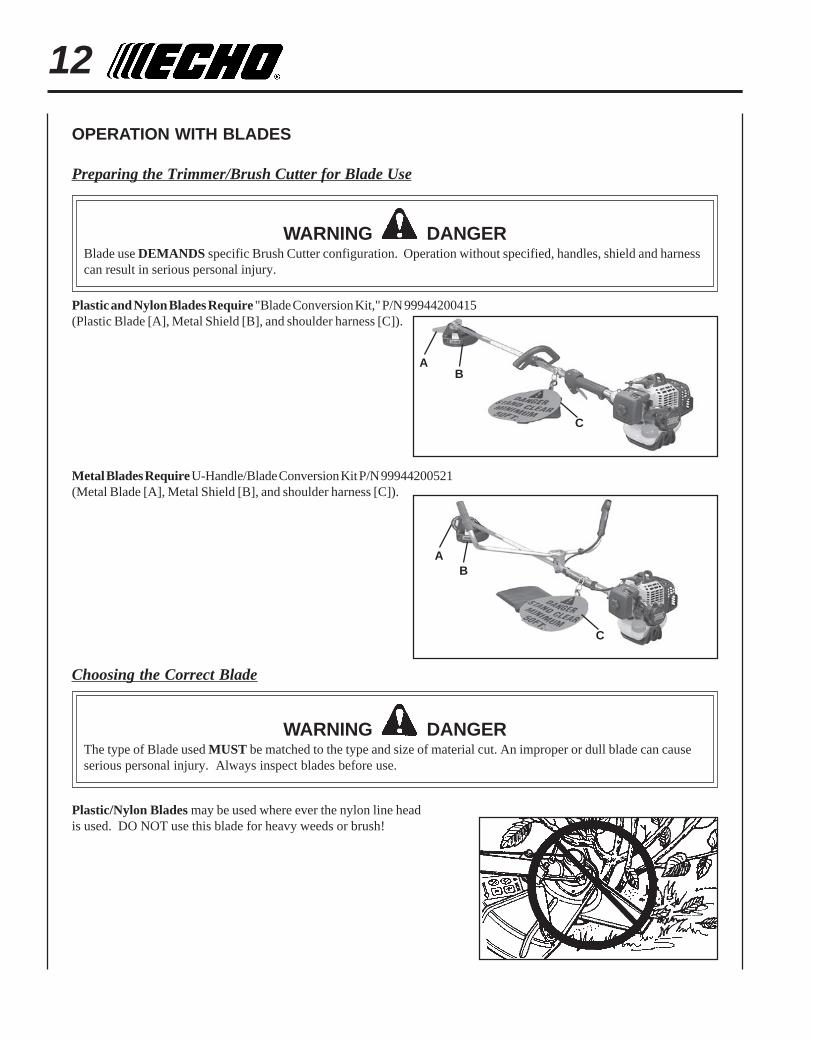
OPERATION WITH BLADES
Preparing the Trimmer/Brush Cutter for Blade Use
WARNING DANGERBlade use DEMANDS specific Brush Cutter configuration. Operation without specified, handles, shield and harnesscan result in serious personal injury.
BA
Plastic and Nylon Blades Require "Blade Conversion Kit," P/N 99944200415(Plastic Blade [A], Metal Shield [B], and shoulder harness [C]).
C
BA
C
Metal Blades Require U-Handle/Blade Conversion Kit P/N 99944200521(Metal Blade [A], Metal Shield [B], and shoulder harness [C]).
Choosing the Correct Blade
WARNING DANGERThe type of Blade used MUST be matched to the type and size of material cut. An improper or dull blade can causeserious personal injury. Always inspect blades before use.
Plastic/Nylon Blades may be used where ever the nylon line headis used. DO NOT use this blade for heavy weeds or brush!

GRASS TRIMMER/BRUSH CUTTEROPERATOR'S MANUAL 13
8 Tooth Weed/Grass Blade (P/N 69600120331) is designed for grass,garden debris and thick weeds. DO NOT use this blade for brush orheavy woody growth, 3/4" in. (19 mm) diameter or larger.
Brush/Clearing Blade (P/N 69500120330) is designed for cutting brushand woody growth up to 3" in. (76 mm) diameter.
Use Shoulder/Waist Harness (P/N 30100052131) Use of the Shoulder/Waist Harness reduces operator fatigue and the possibility of bladecontact with the operators hands and feet by restricting trimmermovement.
HARNESS CLAMP INSTALLATION(Plastic or Nylon Blade Use)
Tools Required: Screwdriver, 8mm x 10mm Open End Wrench.
1. Remove shield and gear housing as an assembly.a. Loosen two (2) screws (A) that clamp the gear housing to the
drive shaft housing.b. Remove locating screw (B) found at the top of the gear
housing. Pull shield and gear housing assembly from the driveshaft assembly.
IMPORTANTPrevent drive shaft from sliding from drive shaft housing. If shaftdoes slide free, clean dirt from shaft and re-assemble.
A
B
A

142. Remove front handle.
a. Remove four (4) screws and nuts and handle support fromhandle.
b. Remove handle.
3. Install clamp and front handle.
4. Install gear housing with metal shield and blade. (See Metal Shieldand Blade Installation Instructions on page 14.
5. Balance unit.
a. Put on harness and attach unit to harness.
b. Slide harness clamp (C) up or down until unit balances withcutting attachment approximately 2 - 3 in. from the ground.
c. Tighten harness clamp screw.
C
METAL SHIELD INSTALLATION(Plastic or metal blade use)
Tools Required: 8mm x 10mm Open End Wrench, Screwdriver.
Parts Required: Metal Shield, Bracket, 3 - 5mm x 15mm screwsw/captivated flat and lockwasher (metal shield to gear housing),2 - 5mm x 8mm screws, 4 - 5mm nuts, 4 - 5mm lockwashers (bracket toshield and bracket to gear housing).
1. If necessary, remove nylon line head and plastic shield.
2. Loosely attach bracket (A) to shield (B) and attach to bottom ofgear housing (C) with screws and nuts provided. Tighten allattaching hardware.
Install Blade
Tools Required: Locking Tool, scrench.
Parts Required: 1 - 20mm Upper Fixing Plate, Grass Blade(69600120330), Brush Blade (69500120330) or Tri-Cut Blade w/Glide Cup(99944200030), 1 - Lower Fixing Plate, 1 - 10mm L.H. Nut, 1 - 2x22mmSplit Pin.
SRM-261/261S
D

GRASS TRIMMER/BRUSH CUTTEROPERATOR'S MANUAL 15
3. Install upper plate (D) on splined shaft. Blade installation requiresuse of Upper Plate (D) with 20mm pilot. Upper plate with 37mm pilotof the SRM-261/261S should be retained for use with nylon linehead.
4. Place Blade (E) over upper plate pilot, install the Lower Plate (F)and 10mm LH nut (G). Tri-Cut Blade (H) is installed with GlideCup (J).
5. Insert Locking Tool (K) through hole in upper plate and notch ingear housing to prevent splined shaft from turning. Tighten nutand secure with Split Pin (L).
U-HANDLE INSTALLATION(Metal blade use)Tools Required: 8mm x 10mm Open End Wrench, Screwdriver, 3mmand 4mm Hex Wrench, Pliers
Parts Required: U-Handle/Blade Conversion Kit P/N 99944200451.
1. Close choke and remove air filter cover.
2. Disconnect ignition stop leads (A) and (B).
3. Remove inner throttle linkage from carburetor swivel (C).
4. Loosen nut (D) and remove throttle linkage from bracket.
5. Loosen bolt (E) and pull drive shaft assembly from clutch case.
6. Loosen two (2) rear handle screws (F) and pull rear handle (G) fromthe drive shaft assembly.
7. Loosen four (4) screws (H) and remove front handle.
8. Position lower U-Handle bracket (J) 400mm (15-3/4 in.) fromengine end of drive shaft. Secure with three (3) 5mm x 30mmbolts.
9. Position harness hook 220mm (8-5/8 in.) from engine end of driveshaft assembly. DO NOT tighten at this time.
A
B
CD
400 mm (15-3/4 in.)
220 mm(8-21/32 in.)
ENGINEEND
J
EF
H
G
16
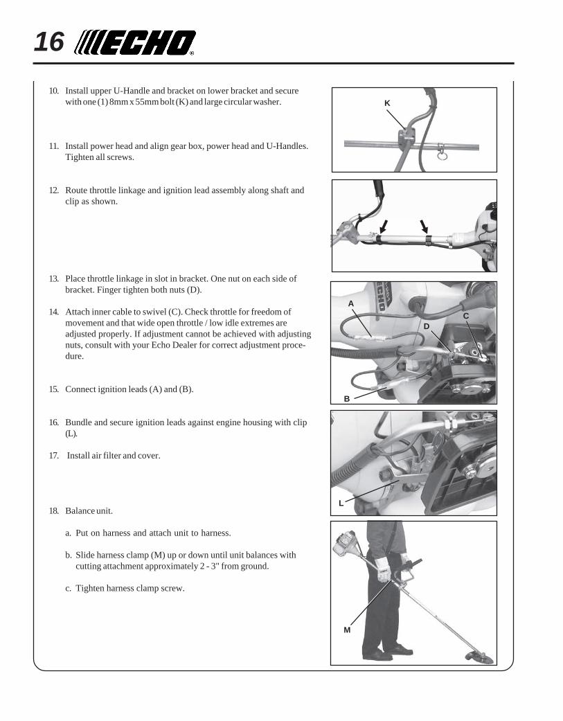
10. Install upper U-Handle and bracket on lower bracket and securewith one (1) 8mm x 55mm bolt (K) and large circular washer.
11. Install power head and align gear box, power head and U-Handles.Tighten all screws.
12. Route throttle linkage and ignition lead assembly along shaft andclip as shown.
13. Place throttle linkage in slot in bracket. One nut on each side ofbracket. Finger tighten both nuts (D).
14. Attach inner cable to swivel (C). Check throttle for freedom ofmovement and that wide open throttle / low idle extremes areadjusted properly. If adjustment cannot be achieved with adjustingnuts, consult with your Echo Dealer for correct adjustment proce-dure.
15. Connect ignition leads (A) and (B).
16. Bundle and secure ignition leads against engine housing with clip(L).
17. Install air filter and cover.
18. Balance unit.
a. Put on harness and attach unit to harness.
b. Slide harness clamp (M) up or down until unit balances withcutting attachment approximately 2 - 3" from ground.
c. Tighten harness clamp screw.
K
M
A
B
CD
L
GRASS TRIMMER/BRUSH CUTTEROPERATOR'S MANUAL 17
PRE - OPERATION
FUEL
Fuel Requirements
Gasoline - Use 89 Octane [ ] (mid grade or higher) gasoline knownto be good quality. Gasoline may contain up to 15% MTBE (methyltertiary-butyl ether). Gasohol containing methyl (wood) alcohol is NOTapproved.
Two Stroke Oil - A two-stroke engine oil meeting ISO-L-EGD (ISO/CD13738) and J.A.S.O. FC Standards, must be used. Echo brand Premium50:1 oil meets these standards. Engine problems due to inadequatelubrication caused by failure to use an ISO-L-EGD and J.A.S.O. FCcertified oil, such as Echo Premium 50:1 Two-stroke Oil, will void thetwo-stroke engine warranty. (Emission related parts only are coveredfor two years, regardless of two-stroke oil used, per the statement listedin the California Emission Defect Warranty Explanation.)
IMPORTANTEcho Premium 2-Stroke Oil may be mixed at 50:1 ratio for applicationin all Echo engines sold in the past regardless of ratio specified inthose manuals.
Mixing Instructions1. Fill an approved fuel container with half of the required amount of
gasoline.2. Add 2-stroke oil to gasoline.3. Close container and shake to mix oil with gasoline.4. Add remaining gasoline and remix.5. Install fuel container cap and wipe any spilled fuel from container
and surrounding area.
Handling Fuel
WARNING DANGERFuel is VERY flammable. Use extreme care when mixing, storing orhandling, otherwise serious personal injury may result.• Use an approved fuel container.• DO NOT smoke near fuel.• DO NOT allow flames or sparks near fuel.• Fuel tanks/cans may be under pressure. Always loosen fuel caps
slowly allowing pressure to equalize.• NEVER refuel a unit when the engine is HOT!• NEVER refuel a unit with the engine running.• DO NOT fill fuel tanks indoors. ALWAYS fill fuel tanks outdoors
over bare ground.• Securely tighten fuel cap after refueling.• Inspect for fuel leakage. If fuel leakage is found, do not start or
operate unit until leakage is repaired.
R + M2 IMPORTANT
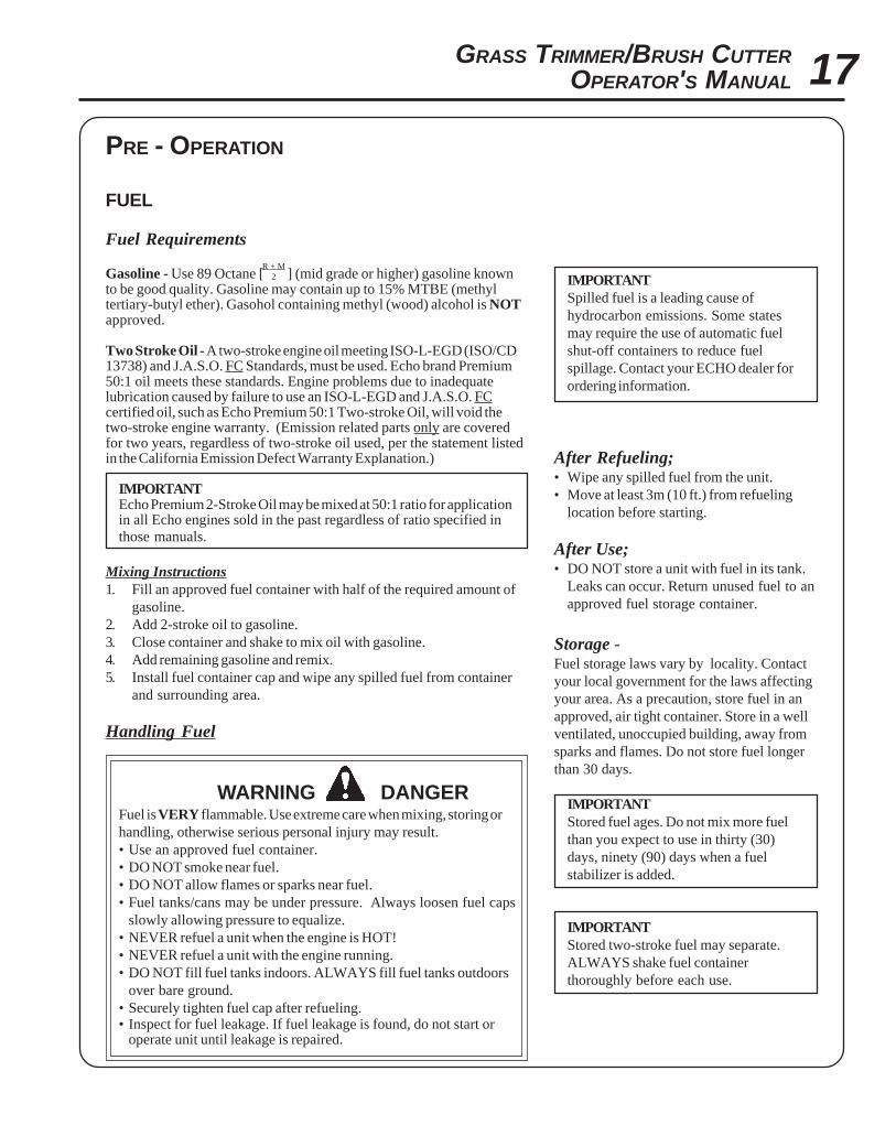
Spilled fuel is a leading cause ofhydrocarbon emissions. Some statesmay require the use of automatic fuelshut-off containers to reduce fuelspillage. Contact your ECHO dealer forordering information.
After Refueling;• Wipe any spilled fuel from the unit.• Move at least 3m (10 ft.) from refueling
location before starting.
After Use;• DO NOT store a unit with fuel in its tank.
Leaks can occur. Return unused fuel to anapproved fuel storage container.
Storage -Fuel storage laws vary by locality. Contactyour local government for the laws affectingyour area. As a precaution, store fuel in anapproved, air tight container. Store in a wellventilated, unoccupied building, away fromsparks and flames. Do not store fuel longerthan 30 days.
IMPORTANTStored fuel ages. Do not mix more fuelthan you expect to use in thirty (30)days, ninety (90) days when a fuelstabilizer is added.
IMPORTANTStored two-stroke fuel may separate.ALWAYS shake fuel containerthoroughly before each use.

18
OPERATION
STARTING COLD ENGINE
WARNING DANGERThe cutting attachment should not rotate at idle. If attachmentrotates, readjust carburetor according to "Carburetor Adjustment"instructions in this manual or see your ECHO Dealer, otherwiseserious personal injury may result.
1. Stop Switch - Start/Run.Move stop switch button (A) forward away from the STOPposition.
2. Close Choke - Cold Start.Move choke lever (B) to Cold Start Position.
3. Primer - Pump Bulb.Pump primer bulb (C) until fuel is visible and flows freely in theclear fuel tank return line. Pump bulb an additional 4 or 5 times.
4. Start - Pull Rope.Lay the trimmer on a flat clear area and pull the recoil starter handle(D) until engine fires (5 or 6 pulls).
5. Open Choke - Run.Move the choke lever to the OPEN - RUN position. Restart engineif necessary and allow to warm up running at idle for severalminutes.
D
C
B
A
GRASS TRIMMER/BRUSH CUTTEROPERATOR'S MANUAL 19
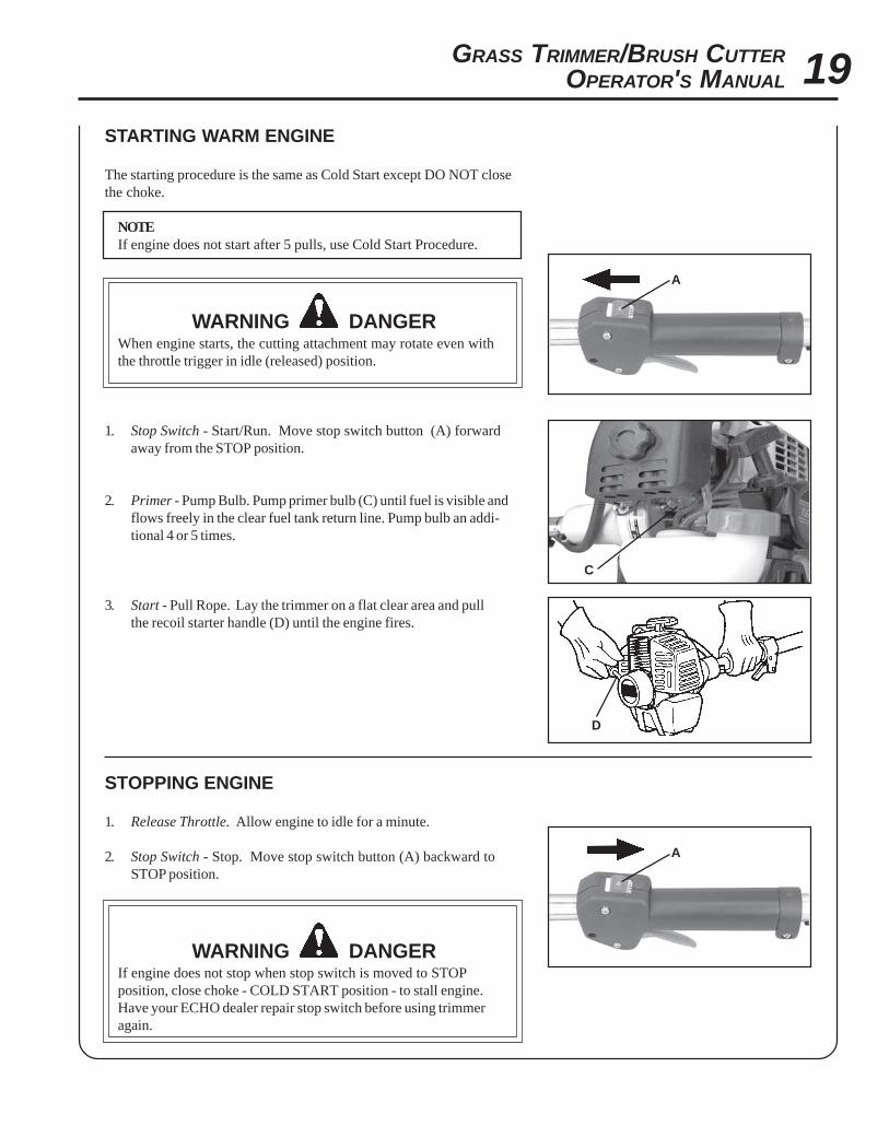
STARTING WARM ENGINE
The starting procedure is the same as Cold Start except DO NOT closethe choke.
NOTEIf engine does not start after 5 pulls, use Cold Start Procedure.
WARNING DANGERWhen engine starts, the cutting attachment may rotate even withthe throttle trigger in idle (released) position.
1. Stop Switch - Start/Run. Move stop switch button (A) forwardaway from the STOP position.
2. Primer - Pump Bulb. Pump primer bulb (C) until fuel is visible andflows freely in the clear fuel tank return line. Pump bulb an addi-tional 4 or 5 times.
3. Start - Pull Rope. Lay the trimmer on a flat clear area and pullthe recoil starter handle (D) until the engine fires.
STOPPING ENGINE
1. Release Throttle. Allow engine to idle for a minute.
2. Stop Switch - Stop. Move stop switch button (A) backward toSTOP position.
WARNING DANGERIf engine does not stop when stop switch is moved to STOPposition, close choke - COLD START position - to stall engine.Have your ECHO dealer repair stop switch before using trimmeragain.
D
C
A
A
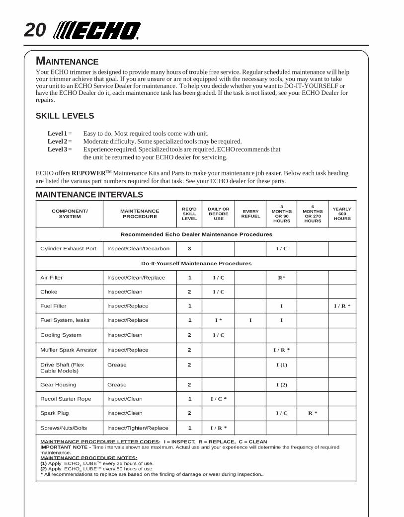
20MAINTENANCEYour ECHO trimmer is designed to provide many hours of trouble free service. Regular scheduled maintenance will helpyour trimmer achieve that goal. If you are unsure or are not equipped with the necessary tools, you may want to takeyour unit to an ECHO Service Dealer for maintenance. To help you decide whether you want to DO-IT-YOURSELF orhave the ECHO Dealer do it, each maintenance task has been graded. If the task is not listed, see your ECHO Dealer forrepairs.
SKILL LEVELS
Level 1 = Easy to do. Most required tools come with unit.Level 2 = Moderate difficulty. Some specialized tools may be required.Level 3 = Experience required. Specialized tools are required. ECHO recommends that
the unit be returned to your ECHO dealer for servicing.
ECHO offers REPOWERTM Maintenance Kits and Parts to make your maintenance job easier. Below each task headingare listed the various part numbers required for that task. See your ECHO dealer for these parts.
MAINTENANCE INTERVALS
/TNENOPMOCMETSYS
ECNANETNIAMERUDECORP
D'QERLLIKSLEVEL
ROYLIADEROFEB
ESU
YREVELEUFER
3SHTNOM
09ROSRUOH
6SHTNOM
072ROSRUOH
YLRAEY006
SRUOH
serudecorPecnanetniaMrelaeDohcEdednemmoceR
troPtsuahxErednilyC nobraceD/naelC/tcepsnI 3 C/I
serudecorPecnanetniaMflesruoY-tI-oD
retliFriA ecalpeR/naelC/tcepsnI 1 C/I *R
ekohC naelC/tcepsnI 2 C/I
retliFleuF ecalpeR/tcepsnI 1 I *R/I
skael,metsySleuF ecalpeR/tcepsnI 1 *I I I
metsySgnilooC naelC/tcepsnI 2 C/I
rotserrAkrapSrelffuM ecalpeR/tcepsnI 2 *R/I
xelF(tfahSevirD)sledoMelbaC
esaerG 2 )1(I
gnisuoHraeG esaerG 2 )2(I
epoRretratSlioceR naelC/tcepsnI 1 *C/I
gulPkrapS naelC/tcepsnI 2 C/I *R
stloB/stuN/swercS ecalpeR/nethgiT/tcepsnI 1 *R/I
SEDOCRETTELERUDECORPECNANETNIAM NAELC=C,ECALPER=R,TCEPSNI=I:-ETONTNATROPMI deriuqerfoycneuqerfehtenimretedlliwecneirepxeruoydnaesulautcA.mumixameranwohsslavretniemiT
.ecnanetniam:SETONERUDECORPECNANETNIAM
)1( OHCEylppA ® EBUL MT .esufosruoh52yreve)2( OHCEylppA ® EBUL MT .esufosruoh05yreve
* ..noitcepsnignirudraewroegamadfognidnifehtnodesaberaecalperotsnoitadnemmocerllA
GRASS TRIMMER/BRUSH CUTTEROPERATOR'S MANUAL 21
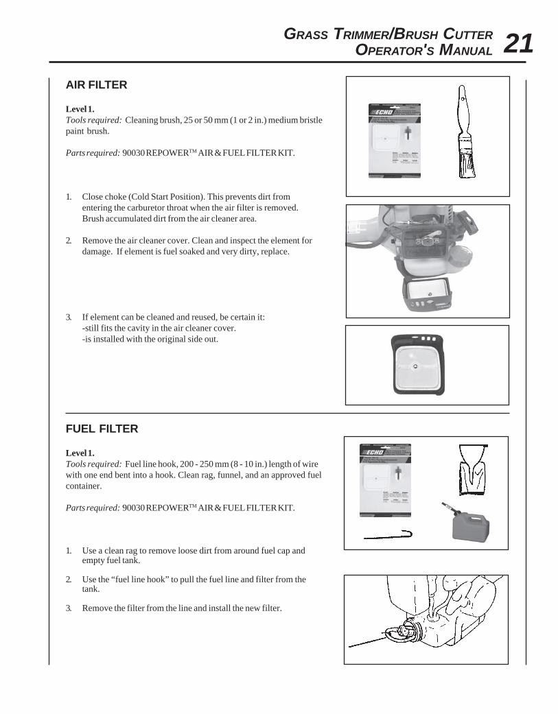
AIR FILTER
Level 1.Tools required: Cleaning brush, 25 or 50 mm (1 or 2 in.) medium bristlepaint brush.
Parts required: 90030 REPOWERTM AIR & FUEL FILTER KIT.
1. Close choke (Cold Start Position). This prevents dirt fromentering the carburetor throat when the air filter is removed.Brush accumulated dirt from the air cleaner area.
2. Remove the air cleaner cover. Clean and inspect the element fordamage. If element is fuel soaked and very dirty, replace.
3. If element can be cleaned and reused, be certain it:-still fits the cavity in the air cleaner cover.-is installed with the original side out.
FUEL FILTER
Level 1.Tools required: Fuel line hook, 200 - 250 mm (8 - 10 in.) length of wirewith one end bent into a hook. Clean rag, funnel, and an approved fuelcontainer.
Parts required: 90030 REPOWERTM AIR & FUEL FILTER KIT.
1. Use a clean rag to remove loose dirt from around fuel cap andempty fuel tank.
2. Use the “fuel line hook” to pull the fuel line and filter from thetank.
3. Remove the filter from the line and install the new filter.
22
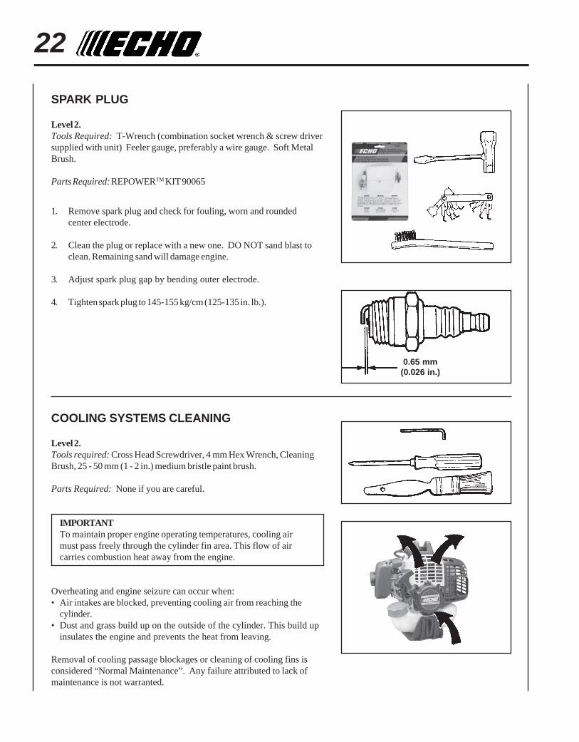
SPARK PLUG
Level 2.Tools Required: T-Wrench (combination socket wrench & screw driversupplied with unit) Feeler gauge, preferably a wire gauge. Soft MetalBrush.
Parts Required: REPOWERTM KIT 90065
1. Remove spark plug and check for fouling, worn and roundedcenter electrode.
2. Clean the plug or replace with a new one. DO NOT sand blast toclean. Remaining sand will damage engine.
3. Adjust spark plug gap by bending outer electrode.
4. Tighten spark plug to 145-155 kg/cm (125-135 in. lb.).
COOLING SYSTEMS CLEANING
Level 2.Tools required: Cross Head Screwdriver, 4 mm Hex Wrench, CleaningBrush, 25 - 50 mm (1 - 2 in.) medium bristle paint brush.
Parts Required: None if you are careful.
IMPORTANTTo maintain proper engine operating temperatures, cooling airmust pass freely through the cylinder fin area. This flow of aircarries combustion heat away from the engine.
Overheating and engine seizure can occur when:• Air intakes are blocked, preventing cooling air from reaching the
cylinder.• Dust and grass build up on the outside of the cylinder. This build up
insulates the engine and prevents the heat from leaving.
Removal of cooling passage blockages or cleaning of cooling fins isconsidered “Normal Maintenance”. Any failure attributed to lack ofmaintenance is not warranted.
0.65 mm(0.026 in.)
GRASS TRIMMER/BRUSH CUTTEROPERATOR'S MANUAL 23
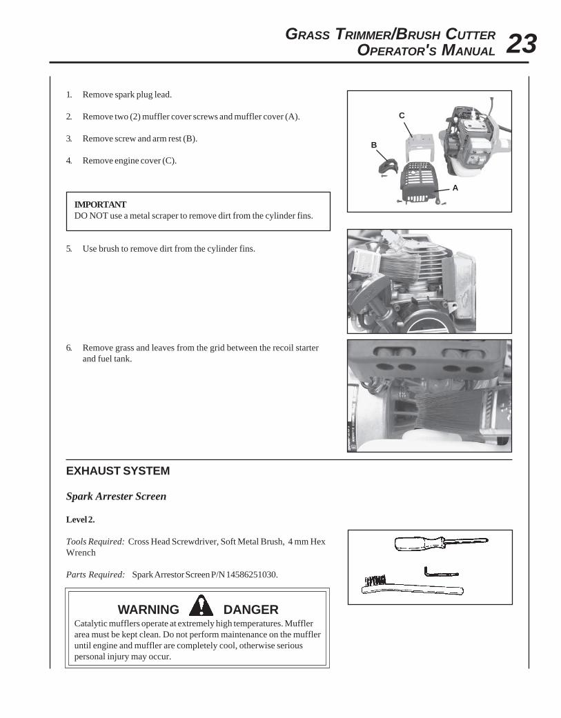
1. Remove spark plug lead.
2. Remove two (2) muffler cover screws and muffler cover (A).
3. Remove screw and arm rest (B).
4. Remove engine cover (C).
IMPORTANTDO NOT use a metal scraper to remove dirt from the cylinder fins.
5. Use brush to remove dirt from the cylinder fins.
6. Remove grass and leaves from the grid between the recoil starterand fuel tank.
EXHAUST SYSTEM
Spark Arrester Screen
Level 2.
Tools Required: Cross Head Screwdriver, Soft Metal Brush, 4 mm HexWrench
Parts Required: Spark Arrestor Screen P/N 14586251030.
WARNING DANGERCatalytic mufflers operate at extremely high temperatures. Mufflerarea must be kept clean. Do not perform maintenance on the muffleruntil engine and muffler are completely cool, otherwise seriouspersonal injury may occur.
A
B
C

241. Remove engine cover (A). See “Cleaning Cooling System” pages
22 & 23 for step by step instructions.
2. Place piston at Top Dead Center (TDC) to prevent carbon/dirt fromentering cylinder.
3. Remove spark arrestor screen cover (B), screen holder (C), gasket(D) and screen (E) from muffler body.
4. Clean carbon deposits from screen and muffler components.
NOTEWhen cleaning carbon deposit, be careful not to damage thecatalytic body.
5. Replace screen if it is cracked, plugged or has holes burnedthrough.
6. Assemble components in reverse order. Be sure spark arrestorscreen is properly seated on muffler.
Cylinder Exhaust Port
Level 3.
IMPORTANTThe cylinder exhaust port must be inspected and cleaned of excesscarbon every 3 months or 90 hours of operation in order to maintainthis engine within the emissions durability period. ECHO stronglyrecommends that you return your unit to your ECHO dealer for thisimportant maintenance service.
CARBURETOR ADJUSTMENT
Engine Break-InNew engines must be operated a minimum duration of two tanks of fuelbreak-in before carburetor adjustments can be made. During the break-in period your engine performance will increase and exhaust emissionswill stabilize. Idle speed can be adjusted as required.
High Altitude AdjustmentHigh altitude adjustment is not required for proper operation of thisengine.
Level 2.Tools required: Screwdriver, Tachometer (ECHO P/N 99051130017).
Parts required: None.
NOTEEvery unit is run at the factory and the carburetor is set in compli-ance with California Emission Regulations. This carburetor doesnot have acceleration and high speed adjustment needles.
A
B
C
D
E
GRASS TRIMMER/BRUSH CUTTEROPERATOR'S MANUAL 25
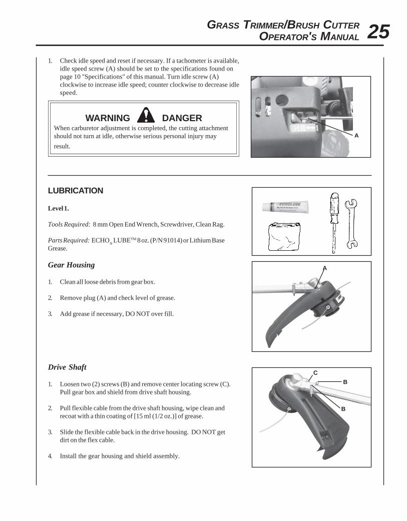
1. Check idle speed and reset if necessary. If a tachometer is available,idle speed screw (A) should be set to the specifications found onpage 10 "Specifications" of this manual. Turn idle screw (A)clockwise to increase idle speed; counter clockwise to decrease idlespeed.
WARNING DANGERWhen carburetor adjustment is completed, the cutting attachmentshould not turn at idle, otherwise serious personal injury may
result.
LUBRICATION
Level 1.
Tools Required: 8 mm Open End Wrench, Screwdriver, Clean Rag.
Parts Required: ECHO® LUBETM 8 oz. (P/N 91014) or Lithium Base
Grease.
Gear Housing
1. Clean all loose debris from gear box.
2. Remove plug (A) and check level of grease.
3. Add grease if necessary, DO NOT over fill.
Drive Shaft
1. Loosen two (2) screws (B) and remove center locating screw (C).Pull gear box and shield from drive shaft housing.
2. Pull flexible cable from the drive shaft housing, wipe clean andrecoat with a thin coating of [15 ml (1/2 oz.)] of grease.
3. Slide the flexible cable back in the drive housing. DO NOT getdirt on the flex cable.
4. Install the gear housing and shield assembly.
A
A
B
C
B
A
26
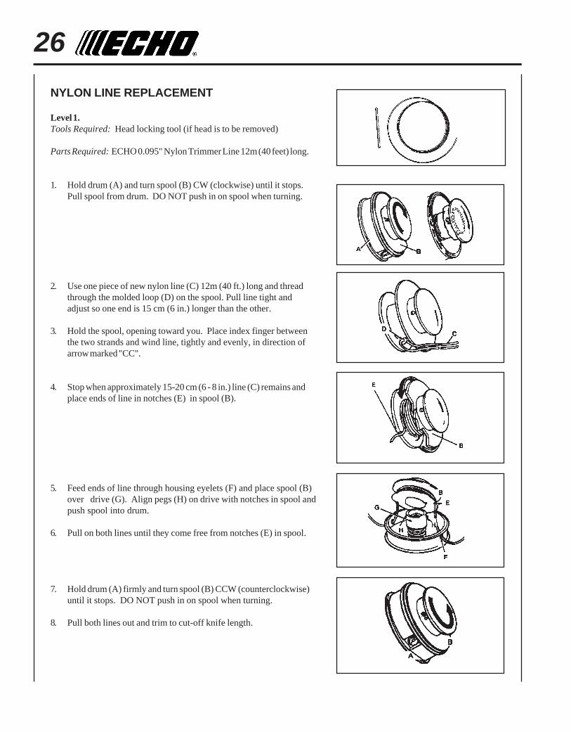
NYLON LINE REPLACEMENT
Level 1.Tools Required: Head locking tool (if head is to be removed)
Parts Required: ECHO 0.095" Nylon Trimmer Line 12m (40 feet) long.
1. Hold drum (A) and turn spool (B) CW (clockwise) until it stops.Pull spool from drum. DO NOT push in on spool when turning.
2. Use one piece of new nylon line (C) 12m (40 ft.) long and threadthrough the molded loop (D) on the spool. Pull line tight andadjust so one end is 15 cm (6 in.) longer than the other.
3. Hold the spool, opening toward you. Place index finger betweenthe two strands and wind line, tightly and evenly, in direction ofarrow marked "CC".
4. Stop when approximately 15-20 cm (6 - 8 in.) line (C) remains andplace ends of line in notches (E) in spool (B).
5. Feed ends of line through housing eyelets (F) and place spool (B)over drive (G). Align pegs (H) on drive with notches in spool andpush spool into drum.
6. Pull on both lines until they come free from notches (E) in spool.
7. Hold drum (A) firmly and turn spool (B) CCW (counterclockwise)until it stops. DO NOT push in on spool when turning.
8. Pull both lines out and trim to cut-off knife length.
GRASS TRIMMER/BRUSH CUTTEROPERATOR'S MANUAL 27
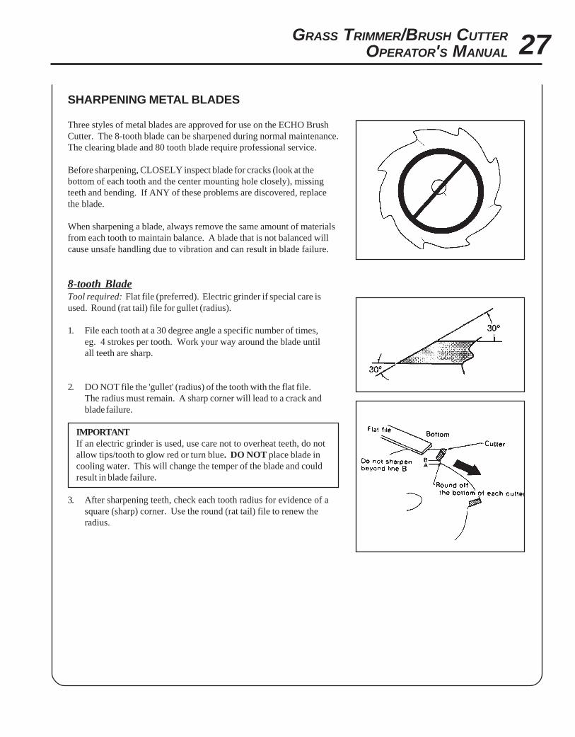
SHARPENING METAL BLADES
Three styles of metal blades are approved for use on the ECHO BrushCutter. The 8-tooth blade can be sharpened during normal maintenance.The clearing blade and 80 tooth blade require professional service.
Before sharpening, CLOSELY inspect blade for cracks (look at thebottom of each tooth and the center mounting hole closely), missingteeth and bending. If ANY of these problems are discovered, replacethe blade.
When sharpening a blade, always remove the same amount of materialsfrom each tooth to maintain balance. A blade that is not balanced willcause unsafe handling due to vibration and can result in blade failure.
8-tooth BladeTool required: Flat file (preferred). Electric grinder if special care isused. Round (rat tail) file for gullet (radius).
1. File each tooth at a 30 degree angle a specific number of times,eg. 4 strokes per tooth. Work your way around the blade untilall teeth are sharp.
2. DO NOT file the 'gullet' (radius) of the tooth with the flat file.The radius must remain. A sharp corner will lead to a crack andblade failure.
IMPORTANTIf an electric grinder is used, use care not to overheat teeth, do notallow tips/tooth to glow red or turn blue. DO NOT place blade incooling water. This will change the temper of the blade and couldresult in blade failure.
3. After sharpening teeth, check each tooth radius for evidence of asquare (sharp) corner. Use the round (rat tail) file to renew theradius.
28
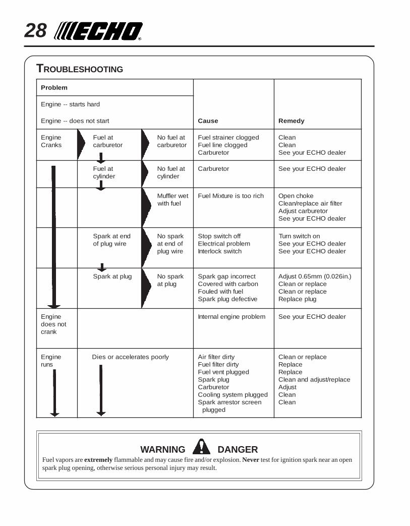
melborP
drahstrats--enignE
tratstonseod--enignE esuaC ydemeR
enignEsknarC
taleuFroterubrac
taleufoNroterubrac
deggolcreniartsleuFdeggolcenilleuF
roterubraC
naelCnaelC
relaedOHCEruoyeeS
taleuFrednilyc
taleufoNrednilyc
roterubraC relaedOHCEruoyeeS
tewrelffuMleufhtiw
hcirootsierutxiMleuF ekohcnepOretlifriaecalper/naelC
roterubractsujdArelaedOHCEruoyeeS
dnetakrapSeriwgulpfo
krapsoNfodnetaeriwgulp
ffohctiwspotSmelborplacirtcelE
hctiwskcolretnI
nohctiwsnruTrelaedOHCEruoyeeSrelaedOHCEruoyeeS
gulptakrapS krapsoNgulpta
tcerrocnipagkrapSnobrachtiwderevoC
leufhtiwdeluoFevitcefedgulpkrapS
).ni620.0(mm56.0tsujdAecalperronaelCecalperronaelC
gulpecalpeR
enignEtonseod
knarc
melborpenignelanretnI relaedOHCEruoyeeS
enignEsnur
ylroopsetareleccaroseiD ytridretlifriAytridretlifleuF
deggulptnevleuFgulpkrapSroterubraC
deggulpmetsysgnilooCneercsrotserrakrapS
deggulp
ecalperronaelCecalpeRecalpeR
ecalper/tsujdadnanaelCtsujdA
naelCnaelC
TROUBLESHOOTING
WARNING DANGERFuel vapors are extremely flammable and may cause fire and/or explosion. Never test for ignition spark near an openspark plug opening, otherwise serious personal injury may result.
GRASS TRIMMER/BRUSH CUTTEROPERATOR'S MANUAL 29
STORAGE
WARNING DANGERDuring operation the muffler or catalytic muffler and surrounding cover become hot. Always keep exhaust area clearof flammable debris during transportation or when storing, otherwise serious property damage or personal injury mayresult.
Long Term Storage (over 30 days)
Do not store your unit for a prolonged period of time (30 days or longer) without performing protective storagemaintenance which includes the following:
1. Store unit in a dry, dust free place, out of the reach of children.
WARNING DANGERDo not store in enclosure where fuel fumes may accumulate orreach an open flame or spark.
7. Remove the spark plug and pour 7 cc (1/4 oz.) (1/2tablespoon) of fresh, clean, two-stroke engine oil intothe cylinder through the spark plug hole.
A. Place a clean cloth over the spark plug hole.B. Pull the recoil starter handle 2-3 times to
distribute the oil inside the engine.C. Observe the piston location through the spark
plug hole. Pull the recoil starter handle slowlyuntil the piston reaches the top of its travel andleave it there.
8. Install the spark plug (do not connect ignition cable).
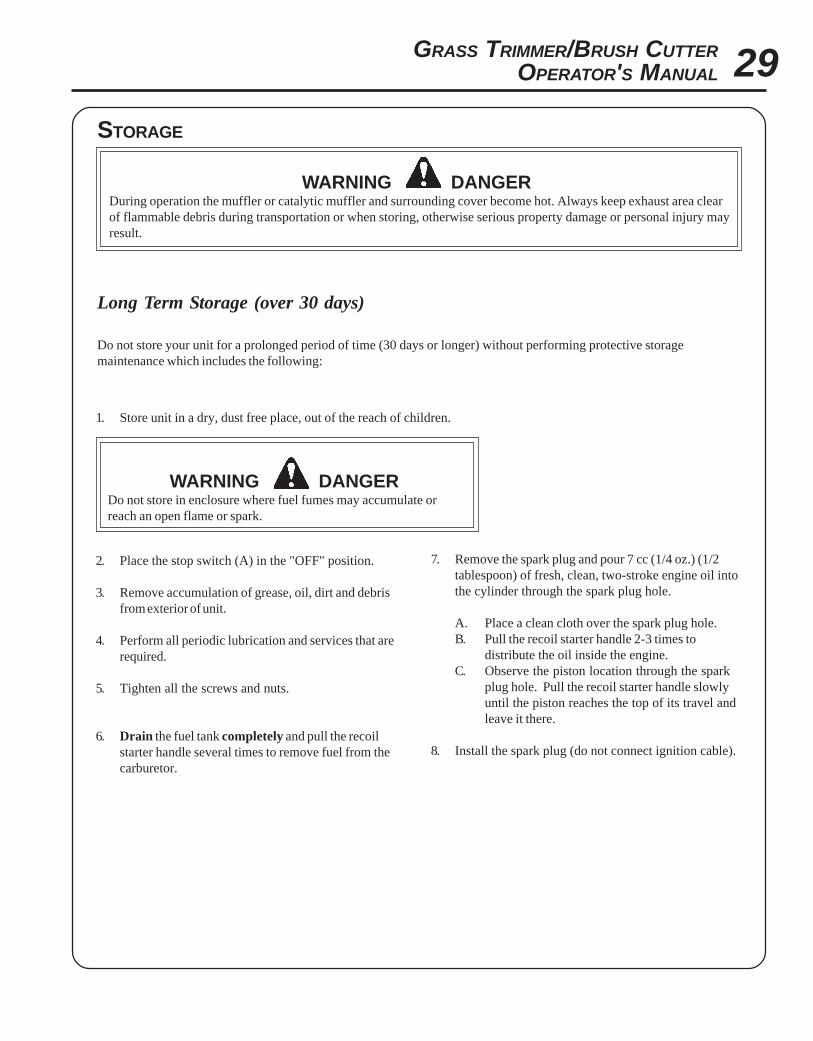
2. Place the stop switch (A) in the "OFF" position.
3. Remove accumulation of grease, oil, dirt and debrisfrom exterior of unit.
4. Perform all periodic lubrication and services that arerequired.
5. Tighten all the screws and nuts.
6. Drain the fuel tank completely and pull the recoilstarter handle several times to remove fuel from thecarburetor.

30
NOTES

GRASS TRIMMER/BRUSH CUTTEROPERATOR'S MANUAL 31
NOTES

SERVICING INFORMATION
PARTSGenuine ECHO Parts and ECHO REPOWER™ Parts and Assemblies foryour ECHO products are available only from an Authorized ECHODealer. When you do need to buy parts always have the ModelNumber and Serial Number of the unit with you. You can find thesenumbers on the engine housing. For future reference, write them in thespace provided below.
Model No. _____________ SN. ____________
SERVICEService of this product during the warranty period must be performedby an Authorized ECHO Service Dealer. For the name and address ofthe Authorized ECHO Service Dealer nearest you, ask your retailer orcall: 1-800-432-ECHO (3246). Dealer information is also available on ourWeb Site. When presenting your unit for Warranty service/repairs,proof of purchase is required.
ECHO CONSUMER PRODUCT SUPPORTIf you require assistance or have questions concerning the application,operation or maintenance of this product you may call the ECHOConsumer Product Support Department at 1-800-673-1558 from 8:30 amto 4:30 pm (Central Standard Time) Monday through Friday. Beforecalling, please know the model and serial number of your unit to helpyour Consumer Product Support Representative.
WARRANTY REGISTRATIONYou may register your Echo equipment using the warranty registrationcard or register on-line at www.echo-usa.com. Registering provides adirect link between you and ECHO if we find it necessary to contactyou.
ADDITIONAL OR REPLACEMENT MANUALS
ECHO, INCORPORATED400 OAKWOOD ROAD
LAKE ZURICH, IL 60047-1564www.echo-usa.com
DEALER?CALL
1-800-432-ECHOOR
www.echo-usa.com
CONSUMER PRODUCTSUPPORT
1-800-673-15588:30 - 4:30 MON - FRI C.S.T.
Safety Manuals in English/Spanish or English/French are available, free of charge, from your ECHO dealer or atwww.echo-usa.com.Operator's and Parts Manuals are available by:• Downloading free from www.echo-usa.com• Purchasing from your Echo Dealer.• Sending a check or money order for $2.00 per Parts Catalog or $1.50 per Operator's Manual made payable to ECHO,
INCORPORATED. State on a sheet of paper the model number and serial number of the ECHO unit you have, partnumber of the manual (if known), your name and address and mail to address below.
Safety Videos are available from your Echo dealer. A $5.00 shipping charge will be required for each video.
Available Parts Catalog Parts Lists
SRM-261/261S S/N 002001001 & UP PART NUMBER 99922203166