Embed Size (px)
Citation preview

277
Pure Appl. Chem., Vol. 80, No. 2, pp. 277–410, 2008.doi:10.1351/pac200880020277© 2008 IUPAC
INTERNATIONAL UNION OF PURE AND APPLIED CHEMISTRY
CHEMICAL NOMENCLATURE AND STRUCTURE REPRESENTATION DIVISION*
GRAPHICAL REPRESENTATION STANDARDS FOR CHEMICAL STRUCTURE DIAGRAMS**
(IUPAC Recommendations 2008)
Prepared for publication byJONATHAN BRECHER
CambridgeSoft Corporation, 100 CambridgePark Drive, Cambridge, MA 02140, USA
*Membership of the Division Committee when this report was approved was as follows: President: G. P. Moss (UK); Past President: A. D. McNaught (UK); Secretary: W. H. Powell (USA); TitularMembers: T. Damhus (Denmark), R. M. Hartshorn (New Zealand), S. R. Heller (USA), K.-H. Hellwich(Germany), J. Kahovec (Czech Republic), J. Nyitrai (Hungary), A. Yerin (Russia); Associate Members: J. Brecher(USA), F. Cozzi (Italy), A. T. Hutton (South Africa), R. G. Jones (UK), G. J. Leigh (UK), J. Wilson (USA);National Representatives: R. Hoyos de Rossi (Argentina), L. F. Lindoy (Australia), I. L. Dukov (Bulgaria),S. S. Krishnamurthy (India), P. Righi (Italy), Y. Do (Korea), J. Reedijk (Netherlands), F. L. Ansari (Pakistan),M. Putala (Slovakia), J. M. Ragnar (Sweden); Ex Officio: D. Schomburg (Germany).
**Developed by the Task Group for Graphical Representation Standards for Chemical Structure Diagrams:Chairman: W. Town (UK); Members: J. Brecher (USA), K. N. Degtyarenko (UK), H. Gottlieb (USA),R. M. Hartshorn (New Zealand), K.-H. Hellwich (Germany), J. Kahovec (Czech Republic), G. P. Moss (UK),A. McNaught (UK), J. Nyitrai (Hungary), W. Powell (USA), A. Smith (USA), K. Taylor (USA), A. Williams(USA), A. Yerin (Russia); Corresponding Members: S. Conway (UK), P. Giles (USA), M. Griffiths (USA),B. Košata (Czech Republic), B. Ramsay (USA).
Comments and suggestions for future revisions of these recommendations may be sent to Jonathan Brecher([email protected]) or to the Secretary of the Division.
Republication or reproduction of this report or its storage and/or dissemination by electronic means is permitted without theneed for formal IUPAC permission on condition that an acknowledgment, with full reference to the source, along with use of thecopyright symbol ©, the name IUPAC, and the year of publication, are prominently visible. Publication of a translation intoanother language is subject to the additional condition of prior approval from the relevant IUPAC National AdheringOrganization.
Graphical representation standards for chemical structure diagrams
(IUPAC Recommendations 2008)
Abstract: The purpose of a chemical structure diagram is to convey information—typically the identity of a molecule—to another human reader or as input to a com-puter program. Any form of communication, however, requires that all participantsunderstand each other. Recommendations are provided for the display of two-di-mensional chemical structure diagrams in ways that avoid ambiguity and are likelyto be understood correctly by all viewers. Examples are provided in many areas,ranging from issues of typography and color selection to the relative positioningof portions of a diagram and the rotational alignment of the diagram as a whole.Explanations describe which styles are preferred and which should be avoided.Principal recommendations include:
• Know your audience: Diagrams that have a wide audience should be drawnas simply as possible.
• Avoid ambiguous drawing styles.• Avoid inconsistent drawing styles.
Keywords: graphical representation; recommendations, graphical; IUPACChemical Nomenclature and Structure Representation Division; chemical struc-tures; chemical structure diagrams.
CONTENTS
GR-0. INTRODUCTION0.1 Overview0.2 Presentation media0.3 Text0.4 Lines0.5 Colors0.6 Size of diagrams
GR-1. BONDS1.1 Bond lengths1.2 Bond widths1.3 Bond patterns1.4 Terminal single bonds1.5 Bonds with bends1.6 Multiple bonds1.7 Coordination bonds1.8 Partial bonds1.9 Multi-center bonds1.10 Sidedness of double bonds
GR-2. ATOM LABELS AND OTHER CHEMICALLY SIGNIFICANT TEXT2.1 Elemental atom labels2.2 Structural abbreviations
J. BRECHER
© 2008 IUPAC, Pure and Applied Chemistry 80, 277–410
278

2.3 Atom labels representing more than one non-hydrogen atom2.4 Formulas
GR-3. ORIENTATION OF STRUCTURES3.1 General guidelines for orientation of structures3.2 Orientation of chains3.3 Depiction of rings3.4 Orientation of rings3.5 Positioning of double bonds in rings3.6 Structural classes with standard orientations
GR-4. POSITIONING OF SUBSTITUENTS4.1 Bond angles at chain atoms4.2 Bond angles from rings to substituents4.3 Avoidance of overlap between substituents
GR-5. CHARGES, UNPAIRED ELECTRONS, AND LONE PAIRS5.1 Charges associated with specific atoms5.2 Lone pairs5.3 Unpaired electrons associated with specific atoms5.4 Delocalized charges and unpaired electrons5.5 Radical ions5.6 Partial charges5.7 Polyatomic ions
GR-6. AROMATIC RINGS AND OTHER TYPES OF ELECTRON DELOCALIZATION6.1 Curves should be drawn uniformly6.2 Curves should be solid6.3 Curves represent delocalization6.4 Curves represent no more than delocalization6.5 Curves should only be used when delocalization is being represented
GR-7. SALTS AND RELATED FORMS7.1 Depiction of ionic bonds7.2 Positioning of components7.3 Salts drawn in unspecified form
GR-8. DOUBLE BONDS, DATIVE BONDS, AND CHARGE-SEPARATED FORMS8.1 Nitrogen compounds8.2 Phosphates and related Group V compounds8.3 Sulfoxides, sulfones, sulfimides, and related Group VI compounds
GR-9. VARIABLE ATTACHMENT POINTS AND SUBSTITUENTS9.1 Small substituents9.2 Predefined substituent classes9.3 Variable chain length and ring size9.4 Variable attachment location9.5 Large substituents
GR-10. TAUTOMERSGR-11. ANNOTATIONS
11.1 Atom-based annotation11.2 Bond-based annotation11.3 Structure-based annotation
GR-12. PSEUDOBONDS12.1 Biological macromolecules12.2 Coordination polyhedra12.3 Connectors
© 2008 IUPAC, Pure and Applied Chemistry 80, 277–410
Graphical representation standards for chemical structure diagrams 279

GR-13. LINEAR DRAWING STYLE13.1 Atoms should be labeled13.2 Bonds should be sufficiently long13.3 Substituents should preferentially be upwards13.4 Structure drawing styles should be consistent13.5 Rings are always drawn as rings
TABLESI. Sample drawing styles for publicationsII. Structural abbreviationsIII. Common contracted atom labels
REFERENCES
GR-0. INTRODUCTION
Although chemical structures have been called “the language of chemistry” [1], few documents have at-tempted to provide any sort of guidelines for the production of chemical structure diagrams [2–5]. Thesame task group that produced this document has recently published recommendations on the graphi-cal representation of stereochemical configuration [6], but IUPAC commentary on the subject of over-all graphical representation has been limited to small sections within larger documents, such as a dis-cussion of the preferred orientation of the steroid ring system as part of the recommendations on thenomenclature of steroids [7]. In the 430-page ACS Style Guide, the chapter on “Chemical Structures”occupies only eight pages that include discussions of several topics in addition to simple representation[8]. And yet chemists have strong feelings for how chemical structure diagrams should look, even in theabsence of formal guidelines. Show most chemists a series of diagrams of something as simple as ben-zene, and there will be near-unanimity about which ones are “good” diagrams and which ones are“bad”. As Robert Pirsig writes in Zen and the Art of Motorcycle Maintenance, “But even though Qualitycannot be defined, you know what Quality is!” [9].
Production of good chemical structure depictions will likely always remain something of an artform. There are few cases where it can be said that a specific representation is “right” and that all oth-ers are “wrong”. These guidelines do not try to do that. Rather, they try to codify the sorts of generalrules that most chemists understand intuitively but that have never been collected in a single printeddocument. Adherence to these guidelines should help produce drawings that are likely to be interpretedthe same way by most chemists and, as importantly, that most chemists feel are “good-looking” dia-grams.
The most important advice in any style guide is to know your audience. In the context of theserecommendations, it follows that the more specific the audience for a structure, the less important it isfor that structure to honor the guidelines discussed here. A structure drawn on the back of a table nap-kin will not be drawn with the same accuracy or precision as one that appears in a printed journal. Thereis nothing wrong with that. A napkin drawing has an audience of one—your colleague on the nextstool—while a printed journal has a much broader audience. Similarly, the types of structures that areappropriate for the Journal of Very Specific Chemistry might not be appropriate to Chemical &Engineering News or Science or Nature.
J. BRECHER
© 2008 IUPAC, Pure and Applied Chemistry 80, 277–410
280
The opposite, however, is not true. Structures drawn for a general audience can be understoodwithout problems by a more specific one. Your colleague on the next stool can surely understand anicely printed diagram if he or she can also understand your scribble-on-a-napkin.
Accordingly, these guidelines encourage those styles that are most likely to be understood byeveryone and discourage the use of unusual, archaic, and ambiguous drawing styles.
Throughout these guidelines, you will see two recurring themes: reduction of ambiguity andproper use of context. With no context, the symbol might represent 4 tungsten atoms, 8vanadium atoms, 17 connected carbon atoms, a wiggly bond, or a diagrammatic fracture. A simple linemight represent a single bond, half of a double bond, a free valence, an iodine atom, or a negativecharge. On occasion, it might even represent nothing more than a simple line itself. Context is critical.The end of one bond should not touch the end of another unless they truly are both bound to the sameatom. Text should not be placed near the end of a bond unless it is intended to provide an atom label,or is so visually different from other labels (in font, size, style, color, or some combination of those)that it could not possibly be mistaken for an atom label. If you create diagrams that are difficult to in-terpret, you should not be surprised if people have problems interpreting them.
The same is true when creating diagrams that need to be interpreted by computer. In many ways,computers today are much more demanding than human chemists. Few programs will interpret a blockof text as being an atom label, no matter how close it is to the end of a bond—unless the software istold, specifically, “That’s an atom label”. Fortunately, most software makes it easy to do so. On the otherhand, software programs may let you assign specific meanings to objects that otherwise look identical,so that the symbol could be made to mean 17 connected carbon atoms without any ambi-guity at all.
Whatever your audience, keep it in mind as you create your structural diagrams.
GR-0.1 Overview
The recommendations in this publication are presented approximately in the order that they should beconsidered by an author who is creating a chemical structure diagram. First, it is necessary to decide onbasic drawing styles, including general issues such as colors and font types (GR-0). Drawing styles spe-cific to chemical structure diagrams also need to be considered, primarily those related to the depictionof bonds (GR-1) and labeled atoms (GR-2). Once the basic styles have been chosen, the diagram itselfcan be produced, starting with the overall orientation of the diagram (GR-3) and continuing until allsubstituents have been positioned (GR-4). Other common features, including formal charges and un-paired electrons (GR-5) as well as delocalization (GR-6) have special needs that are considered sepa-rately, while the depiction of salts and related forms (GR-7) requires the relative positioning of severalfragments that have been depicted individually. Various other issues are discussed in the remainder ofthe publication (GR-8 through the end).
Throughout this publication are numerous examples of chemical structures drawn in styles thatare labeled as “preferred”, “acceptable”, “not acceptable”, or occasionally “wrong”. Due to space con-straints in this document, only a few diagrams are shown for each case, with the intention that those ex-amples are representative of the topic being discussed. The presence of one diagram labeled as “pre-ferred” does not preclude the possibility of other “preferred” diagrams, including those with slightdifferences from the depicted structure in terms of bond length, line thickness, localization of doublebonds in aromatic systems, or other minor details. Beyond that, it is worthwhile to clarify further themeaning of those terms as they are used here.
A chemical structure diagram is most commonly used simply as a means of identification, a wayto answer the implied question, “What is the chemical structure of X?” The styles labeled as “preferred”show how the structure should best be depicted in such cases, where there are no other overriding con-cerns. These depiction styles are generally applicable across many classes of chemical structures.
© 2008 IUPAC, Pure and Applied Chemistry 80, 277–410
Graphical representation standards for chemical structure diagrams 281

Sometimes, however, overriding concerns are present. Even simple structures might contain sev-eral ring systems, substituents, and functional groups. The generation of an aesthetic diagram of thewhole molecule might require that individual portions are depicted in ways that would not be ideal ifthat portion were viewed in isolation. The diagrams labeled as “acceptable” indicate additional depic-tion styles that could be considered if the preferred style is inappropriate for some well-considered rea-son.
Many of the structural depictions included in this document are provided as counterexamples, of-fering clarification of how structures should not be shown. Those depictions are labeled as “not ac-ceptable”, indicating that they should be strongly avoided in normal usage. Where possible, they havebeen accompanied by further description of why they are not acceptable, and why the alternative de-pictions are preferred or more acceptable.
Finally, a small number of examples are labeled as simply “wrong”. Those show representationsthat should be avoided in all cases, generally because they depict something that is either self-contra-dictory or because they accurately represent a molecule other than the one intended.
For the sake of readability within this paper, angular measurements of diagrams are listed withexact numerical values, such as 180°. Unless otherwise specified, all such measurements should be con-sidered to be approximate, and specifying a range within roughly 10° of the listed value. The same ap-plies to textual descriptions of angles, so the term “collinear” should be interpreted as “forming an anglebetween 170° and 190°”. In other words, two bonds that look nearly collinear should be treated as ex-actly collinear, even if that is not exactly true for their actual geometric relationship.
Similarly, any mention of bonds being “adjacent” or atoms being “connected to” refers to theirappearance in the two-dimensional representation. Any of the four bonds of an atom with a physical(three-dimensional) tetrahedral configuration is physically adjacent to every other bond, but in a two-dimensional representation it is depicted as adjacent to only two others, and “opposite” to the third. Incyclohexane, each carbon atom is truly “connected to” four atoms: its two neighboring carbon atoms inthe ring, and two external hydrogen atoms. In most diagrams, however, cyclohexane will be depicted asa regular hexagon with the hydrogen atoms implicit but not shown within the diagram. It is useful todescribe those carbon atoms as being connected to only two other atoms, the two neighboring carbonatoms that are explicitly depicted. These conventions will be used throughout this publication.
The recommendations in this publication are intended for use in structural diagrams drawn in the“standard” two-dimensional format where single bonds are represented with one line segment connect-ing a pair of atoms, double bonds are represented with two parallel line segments connecting a pair ofatoms, atoms are labeled with atomic symbols (or not shown at all in the case of carbon atoms and thehydrogen atoms bonded to them), and so on. There are other valid ways to represent structures includ-ing Newman projections, ball-and-stick models, and many others. These recommendations should notbe over-generalized as applying to anything beyond the “standard” two-dimensional chemical structurediagrams.
GR-0.2 Presentation media
For the most part, these guidelines are written as in the context of a “perfect” presentation medium,where nothing will detract from the chemical structures themselves. Practical reality will rarely be thatsimple. Some styles that have been recommended for various printed publications are shown and con-trasted in Table I, demonstrating the wide range of well-considered styles that are possible even withina single medium. When preparing diagrams for a low-resolution format such as the World Wide Web,on the other hand, it might be appropriate to make diagrams slightly larger or use a larger font than inprinted journals, so that the diagrams can be read more easily on the computer screen. Presentations inprinted journals have an absolute maximum width determined by the page size of that journal, andstructures have to be sized and positioned accordingly. It is certainly reasonable (and altogether proper)
J. BRECHER
© 2008 IUPAC, Pure and Applied Chemistry 80, 277–410
282

to consider how the structures will eventually be presented and processed. There is no problem in de-viating from these guidelines whenever necessary.
The prevalence of computers in chemical research provides some special problems. Compared tothe number of human chemists, there are very few computer applications designed to process (display,store, search, analyze, etc.) chemical structure diagrams. Chemical structures that are likely to be inter-preted by computer must be considered as having an extremely specific audience, and a fairly stupid oneat that. Even the best computer programs available today are quite sensitive to the way that structuresare drawn. These programs will surely become more intelligent over time, but they will not rival humanintelligence in the near future. In addition to being easily interpretable by humans, structures drawn inthe recommended styles are much more likely to be interpreted correctly by computers.
In some cases, no computer software currently available will be able to interpret a depiction thatis otherwise completely reasonable, even preferred. We have tried to indicate those cases clearly, in sec-tions of this document labeled with the phrase “SOFTWARE CAUTION:”, and we hope that softwarewill evolve over time. If structures are required that must be interpreted by computers now—for exam-ple, for entry in a chemical registration system or for searching of an electronic chemical structure data-base—it is particularly important to understand the strengths and limitations of the software you arecurrently using. Again, structure drawings that follow these guidelines are more likely to be interpretedcorrectly than those that do not.
GR-0.3 Text
Any roman font is acceptable, but plainer fonts are preferred. Times, Times New Roman, Helvetica, andArial are the most commonly seen serif and sans serif fonts, but that list is not exclusive. Normally, thefonts used in a chemical structure should match those used in any associated text, or be different fromthem in a clearly visible way (such as serif vs. sans serif).
Text should be scaled to a size that is comfortable for reading. In printed materials, that is usuallyin the range of 8–14 points. In other media, different sizes might be appropriate; in posters or projec-tions, for example, a much larger size might be required. When increasing the size of text, it will usu-ally also be necessary to increase the length of the bonds in the diagram (GR-1.1). Text that is smallerthan five points in size is too small for most people to read comfortably, and is therefore not acceptable.
Formatting of text, including bold, italic, and underlined styles, should follow standard (non-chemical) style guidelines. For the most part, that means that the majority of text should be unformat-ted. Formatted text could be reasonably used to draw emphasis to a portion of a diagram; if emphasisis required, bold formatting is preferred over the use of italics or underlining because it provides agreater visual difference.
© 2008 IUPAC, Pure and Applied Chemistry 80, 277–410
Graphical representation standards for chemical structure diagrams 283

Within the realm of biochemical structure diagrams only, the capital P symbol has different mean-ings depending on whether it is roman (a phosphorus atom) or italic (an abbreviation that represents ahydroxyphosphoryl or dihydroxyphosphoryl moiety in a phosphate group [10]). Due to the long historyof usage, both the roman and italic forms of the capital P must remain acceptable; however, authorsshould consider that the italicized version may be unfamiliar to readers who are not familiar with bio-chemical nomenclature. For the broadest understanding, it is preferable to depict the phosphorus-con-taining fragments fully with explicit atoms and bonds. It is not acceptable to create new abbreviations(see GR-2.2) whose meaning is changed by the presence or absence of text formatting.
The formatting for text should be used consistently throughout the diagram, whatever specificfonts, font sizes, and font styles are chosen. It is not acceptable to use multiple fonts and styles withina single diagram, again with intentional emphasis being an exception.
Within those general guidelines, many publications have specific preferences regarding the use oftext. When producing diagrams that are to be used by someone else, it is always recommended that au-thors check if there are any additional preferences that need to be followed.
GR-0.4 Lines
Lines are most commonly used in chemical diagrams to represent bonds, but may also be used in astrictly graphical sense, for example, to divide a larger space or as the shaft of an arrow. Most linesshould be drawn at a width that is consistent with the remainder of the drawing, usually close to thewidth of the strokes of any accompanying text. Lines that are thinner than 0.5 points should be avoided.Thicker lines should be reserved for places where emphasis is required or (when drawn as bonds) toemphasize perspective.
J. BRECHER
© 2008 IUPAC, Pure and Applied Chemistry 80, 277–410
284

Within those general guidelines, many publications have specific preferences regarding linewidths just as they often do for text (GR-0.3). When producing diagrams that are to be used by some-one else, it is always recommended that authors check if there are any additional preferences that needto be followed.
GR-0.5 Colors
Except when emphasis is desired, use of color should be avoided, and chemical structures should bedisplayed in the same color as any associated material. Most commonly, that means that the structuresshould be displayed in black on a white background, although some circumstances prefer alternativecoloring schemes (projected transparencies are often displayed as white or yellow on a dark blue orblack background).
When emphasis is desired, colors may be used to provide that emphasis. Any colors used in adocument should be clear and visually distinct. Most commonly, red would be used as the primary colorfor emphasis. A dark blue or dark gray color would be a very poor choice for emphasis in a structurethat is mostly black, and similar choices of low-contrast color combinations should be avoided.
Authors are encouraged to remember that roughly 10 % of men are colorblind [11]. The com-bined use of red and green as contrasting colors in one diagram is strongly discouraged.
Authors of two-dimensional chemical diagrams should also keep in mind that there are traditionalcolors used for specific elements within the realm of three-dimensional modeling. Molecular modelsthat display atoms as spheres will typically color the oxygen atoms as red, nitrogen atoms as blue, chlo-rine atoms as green, and so on, a coloring scheme that dates to an 1865 lecture by A. W. Hofmann wherehe used croquet balls in his demonstrations [12]. In current usage for molecular models, the specificshades of those colors may vary, as may the colors for less common elements. Since it is rarely neces-sary to color two-dimensional diagrams by element type, the traditional colors used in molecular mod-eling are simply not relevant in most cases. When it is desired to color two-dimensional diagrams byelement type, it would be preferable to select a coloring scheme that is consistent with the traditionalcolors of three-dimensional modeling. It is not acceptable to color two-dimensional diagrams usingcolor schemes that directly contradict those colors used for molecular modeling. That is, it is not ac-ceptable to color all oxygen atoms yellow, all nitrogen atoms red, and all sulfur atoms blue within a sin-gle two-dimensional diagram.
GR-0.6 Size of diagrams
For the most part, the overall size of a structure diagram will be determined by the size chosen as thelength of a standard bond and by the recommended angles between bonds in various circumstances asdescribed in the remainder of this document. Although computers can store diagrams of any size, thereare many other situations that impose restrictions on the space available for each structure diagram. Inprinted journals, for example, there is an absolute restriction that every structure must fit on the physi-cal page, and the structures will often need to fit within specific column widths as well. Similarly, low-resolution media, such as the World Wide Web, may require a larger diagram overall in order to main-tain legibility of fine details (see GR-0.2).
For very large, rigid molecules, there is little option but to shrink the diagram uniformly as muchas necessary as to fit within the space available. When diagrams are resized, they should always be re-sized uniformly in both dimensions at the same time, and any associated text (such as atom labels)should be resized by the same amount.
© 2008 IUPAC, Pure and Applied Chemistry 80, 277–410
Graphical representation standards for chemical structure diagrams 285
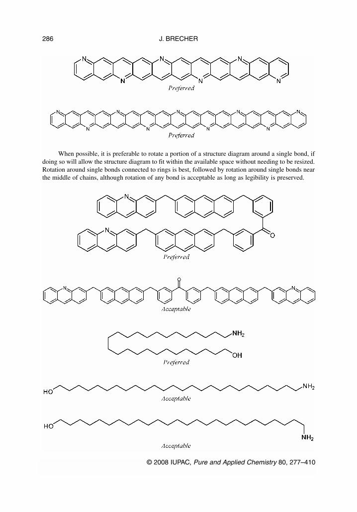
When possible, it is preferable to rotate a portion of a structure diagram around a single bond, ifdoing so will allow the structure diagram to fit within the available space without needing to be resized.Rotation around single bonds connected to rings is best, followed by rotation around single bonds nearthe middle of chains, although rotation of any bond is acceptable as long as legibility is preserved.
J. BRECHER
© 2008 IUPAC, Pure and Applied Chemistry 80, 277–410
286

As discussed in GR-0.3, it is not acceptable to reduce the size of a diagram if doing so would pro-duce atom labels that are illegibly small.
If a portion of a structure diagram is normally depicted in a standard orientation (GR-3.6), thatportion should remain fixed and only the other portion should be rotated.
© 2008 IUPAC, Pure and Applied Chemistry 80, 277–410
Graphical representation standards for chemical structure diagrams 287

An alternative approach to reducing the size of large diagrams is to replace portions of the dia-gram with appropriate abbreviations as discussed in GR-2.2 and GR-2.3. Because abbreviations willoften be much smaller than the portions of the diagram that they replace, their use can also help avoidoverlap when no other options are available to make large diagrams legible.
GR-1. BONDS
In most areas of chemistry, a bond represents an electronic association between two atoms. When draw-ing bonds, therefore, it is important to be unambiguous about (a) the nature of the electronic associa-tion—is the bond in question a single bond, double bond, or a bond of some other order—and (b) whichtwo atoms it joins. Other types of bonding are also possible, including coordination bonds, which arediscussed in GR-1.7. The use of bonds to represent configuration (e.g., using hashes and wedges) is dis-cussed in a separate document [6].
J. BRECHER
© 2008 IUPAC, Pure and Applied Chemistry 80, 277–410
288
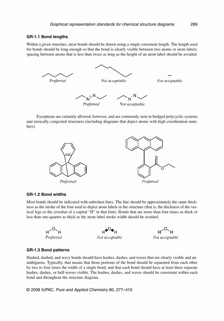
GR-1.1 Bond lengths
Within a given structure, most bonds should be drawn using a single consistent length. The length usedfor bonds should be long enough so that the bond is clearly visible between two atoms or atom labels;spacing between atoms that is less than twice as long as the height of an atom label should be avoided.
Exceptions are certainly allowed, however, and are commonly seen in bridged polycyclic systemsand sterically congested structures (including diagrams that depict atoms with high coordination num-bers).
GR-1.2 Bond widths
Most bonds should be indicated with unbroken lines. The line should be approximately the same thick-ness as the stroke of the font used to depict atom labels in the structure (that is, the thickness of the ver-tical legs or the crossbar of a capital “H” in that font). Bonds that are more than four times as thick orless than one-quarter as thick as the atom label stroke width should be avoided.
GR-1.3 Bond patterns
Hashed, dashed, and wavy bonds should have hashes, dashes, and waves that are clearly visible and un-ambiguous. Typically, that means that those portions of the bond should be separated from each otherby two to four times the width of a single bond, and that each bond should have at least three separatehashes, dashes, or half-waves visible. The hashes, dashes, and waves should be consistent within eachbond and throughout the structure diagram.
© 2008 IUPAC, Pure and Applied Chemistry 80, 277–410
Graphical representation standards for chemical structure diagrams 289

GR-1.4 Terminal single bonds
As discussed in GR-2.1.2, unlabeled atoms are assumed to be carbon atoms, and so terminal singlebonds are assumed to represent methyl groups. Unlabeled bonds should not be used to represent un-specified or variable attachment points (see GR-9), as such diagrams are extremely prone to misinter-pretation.
Shorter-than-usual terminal bonds are especially problematic, as they can be confused not onlywith methyl groups, but also with negative charges. Bonds of this type should be strongly avoided.
GR-1.5 Bonds with bends
Bent bonds are used exclusively in two situations, both relating to the depiction of carbohydrates. Theyare used when representing the glycosidic linkage between two carbohydrates drawn as Haworth pro-jections, where the individual carbohydrate rings must remain in the horizontal orientation required bythe Haworth projections. Even in such cases, it is preferable to depict the glycosidic linkage usingstraight bonds, with the bonds angled slightly from the vertical orientation normally required byHaworth projections. It is acceptable to depict bent bonds in such cases, but they must be drawn assmooth curves. It is not acceptable to depict bent bonds with sharp corners, since such angular bendswithin bonds normally imply CH2 groups, and will always present ambiguity between molecules withthe normal glycosidic –O– linkage and similar analogs that truly do have a larger –CH2–O–CH2– link-age instead.
J. BRECHER
© 2008 IUPAC, Pure and Applied Chemistry 80, 277–410
290

Bent bonds are used also when depicting the cyclic form of carbohydrates in Fischer projections.As in Haworth projections, it is not acceptable to depict the connecting bond with sharp corners, sincethose corners could easily be interpreted as additional CH2 groups.
Those concerns notwithstanding, bent bonds used to indicate closures in cyclic peptides and re-lated molecules (GR-2.2.1) must be depicted with sharp corners, since the curved forms have rarelybeen used and will likely be confusing to a reader unfamiliar with them.
SOFTWARE CAUTION: At the time of writing of this document, the authors know of no com-puter software that is able to represent bonds with smooth curves. If chemical structure diagrams ofpolysaccharides are required for use within an electronic environment, the use of bent bonds may in-deed be not acceptable in that case. However, since there are also few examples of computer softwarethat can properly recognize Haworth projections in any circumstance, it is most preferred to use the flatMills diagrams (as shown in the first Preferred carbohydrate examples above) in situations where poly-saccharides must be interpreted by computer software.
© 2008 IUPAC, Pure and Applied Chemistry 80, 277–410
Graphical representation standards for chemical structure diagrams 291
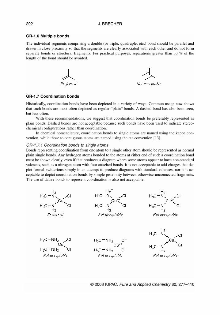
GR-1.6 Multiple bonds
The individual segments comprising a double (or triple, quadruple, etc.) bond should be parallel anddrawn in close proximity so that the segments are clearly associated with each other and do not formseparate bonds or structural fragments. For practical purposes, separations greater than 33 % of thelength of the bond should be avoided.
GR-1.7 Coordination bonds
Historically, coordination bonds have been depicted in a variety of ways. Common usage now showsthat such bonds are most often depicted as regular “plain” bonds. A dashed bond has also been seen,but less often.
With these recommendations, we suggest that coordination bonds be preferably represented asplain bonds. Dashed bonds are not acceptable because such bonds have been used to indicate stereo-chemical configurations rather than coordination.
In chemical nomenclature, coordination bonds to single atoms are named using the kappa con-vention, while those to contiguous atoms are named using the eta convention [13].
GR-1.7.1 Coordination bonds to single atomsBonds representing coordination from one atom to a single other atom should be represented as normalplain single bonds. Any hydrogen atoms bonded to the atoms at either end of such a coordination bondmust be shown clearly, even if that produces a diagram where some atoms appear to have non-standardvalences, such as a nitrogen atom with four attached bonds. It is not acceptable to add charges that de-pict formal zwitterions simply in an attempt to produce diagrams with standard valences, nor is it ac-ceptable to depict coordination bonds by simple proximity between otherwise-unconnected fragments.The use of dative bonds to represent coordination is also not acceptable.
J. BRECHER
© 2008 IUPAC, Pure and Applied Chemistry 80, 277–410
292
SOFTWARE CAUTION: Some existing software may be unable to interpret properly coordina-tion bonds drawn with single bonds and without charges, as recommended above. When creating chem-ical structure diagrams for use with such software, one of the otherwise “not acceptable” forms may infact be the only way to produce a diagram that the software can understand. Authors who need to de-pict coordination bonds for use with chemical software programs should check the requirements ofthose programs before producing the diagrams.
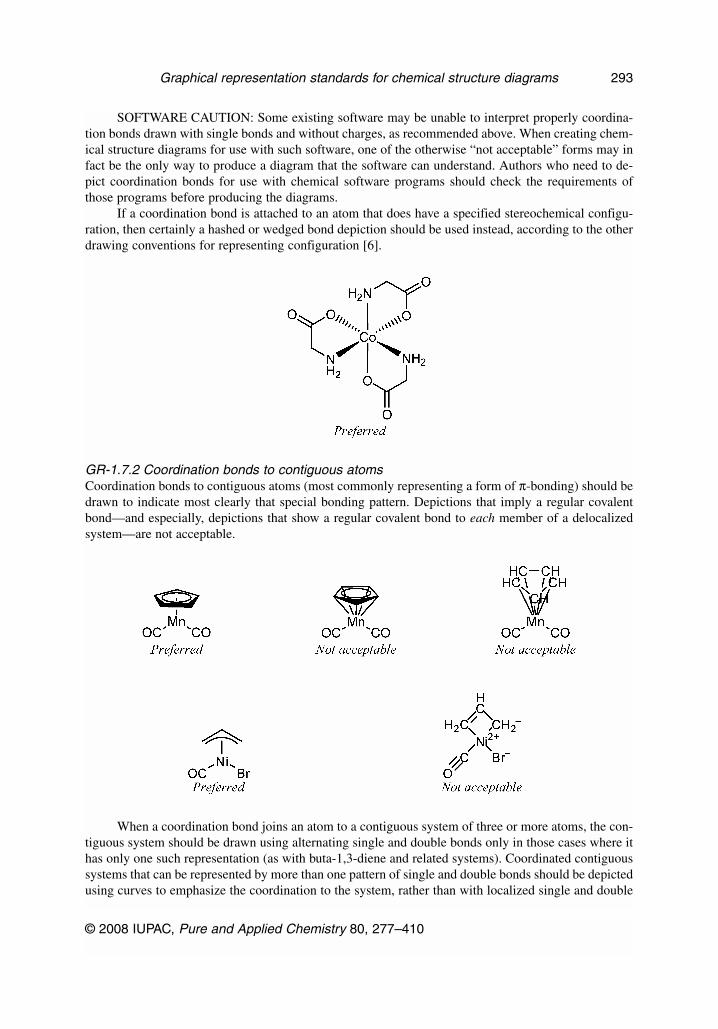
If a coordination bond is attached to an atom that does have a specified stereochemical configu-ration, then certainly a hashed or wedged bond depiction should be used instead, according to the otherdrawing conventions for representing configuration [6].
GR-1.7.2 Coordination bonds to contiguous atomsCoordination bonds to contiguous atoms (most commonly representing a form of π-bonding) should bedrawn to indicate most clearly that special bonding pattern. Depictions that imply a regular covalentbond—and especially, depictions that show a regular covalent bond to each member of a delocalizedsystem—are not acceptable.
When a coordination bond joins an atom to a contiguous system of three or more atoms, the con-tiguous system should be drawn using alternating single and double bonds only in those cases where ithas only one such representation (as with buta-1,3-diene and related systems). Coordinated contiguoussystems that can be represented by more than one pattern of single and double bonds should be depictedusing curves to emphasize the coordination to the system, rather than with localized single and double
© 2008 IUPAC, Pure and Applied Chemistry 80, 277–410
Graphical representation standards for chemical structure diagrams 293

bonds. This is true even if an uncoordinated analog of the same contiguous system normally would berepresented with localized single and double bonds, as with the benzene system within tricarbonyl(η6-benzene)chromium. The use of curves in these molecules is consistent with the preference for usingcurves in systems that cannot be adequately represented by alternating single and double bonds(GR-6.5).
Bonds connecting to delocalized systems should most often be drawn as plain bonds. Solidwedged bonds and hashed wedged bonds might be appropriate when depicting the configuration of theatom on the non-contiguous end of the bond, although even in that case plain bonds would be preferredif it were possible to indicate the configuration using solid wedged bonds or hashed wedged bonds toother substituents.
It is not acceptable to use dashed bonds to show bonding to a delocalized system.
SOFTWARE CAUTION: When working electronically, it is extremely important to specify a co-ordination bond appropriately, according to the capabilities of the software program you are using. Ifthe coordination bond is specified inappropriately, the diagram may be interpreted as two disjoint frag-ments, with the coordination bond being interpreted as a normal bond to an unlabeled carbon atom. Inaddition to losing the intended delocalized character, this misinterpretation will also add an additionalCH3 to the structure’s perceived formula for the “methyl group” at the center of the contiguous system.
J. BRECHER
© 2008 IUPAC, Pure and Applied Chemistry 80, 277–410
294

GR-1.8 Partial bonds
It is often useful to depict an association between atoms that is significantly weaker than a normal co-valent, coordinating, or ionic bond. The most common type of “partial bond” is a hydrogen bond, whichhas been defined as “a form of association between an electronegative atom and a hydrogen atom at-tached to a second, relatively electronegative atom” [14]. The classical hydrogen bond is considered asan electrostatic interaction between polar groups Aδ––Hδ+ and Bδ–: Aδ––Hδ+···Bδ–.
Partial bonds should be represented with dotted lines. As with all types of bonds, dotted bondsshould be long enough to be clearly visible between two atom labels, and bonds that are less than twiceas long as the height of an atom label should be avoided. Dotted bonds should always include at leastthree dots.
SOFTWARE CAUTION: At the time of preparing this document, the authors are unaware of anycomputer software that can produce dotted bonds. In cases where it is not possible to produce true dot-ted bonds, it is acceptable to use dashed bonds instead.
GR-1.9 Multi-center bonds
From a molecular orbital perspective, it is possible to have bonding patterns where a pair of electronsis shared between more than two atoms. This sort of “multi-center” bonding is prevalent in the chem-istry of boron compounds, for example, although it is seen in many other situations as well. As a mat-ter of convention, any such multi-center character is ignored when producing chemical structure dia-grams, and regular bonds connecting pairs of atoms are used instead.
In contrast with the depiction of coordination bonds (GR-1.7.2), curves should not be used whendepicting multi-center bonds.
© 2008 IUPAC, Pure and Applied Chemistry 80, 277–410
Graphical representation standards for chemical structure diagrams 295

GR-1.10 Sidedness of double bonds
Double bonds traditionally appear in three orientations relative to the imaginary line connecting the cen-ters of the atoms on either end of the bond. The double bond may be offset on either side of the center,or it may straddle the center exactly.
If the double bond is offset, one segment should be centered exactly, while the other one is off-set. The segment of the double bond that is offset should usually be shortened at both ends. The amountof the shortening will depend on the spacing between the two segments and on the angles of the ad-joining bonds. For best appearances, the endpoints of the second segment should be positioned so thatthey fall on the bisector of the angle between the double bond and its adjoining bond. If a bond is un-substituted on one end, or if the only substitution on that end is trans relative to the second segment,then the segment should not be shortened on that end.
Because the amount of shortening is dependent on the adjacent angles, it is most pronounced insmall rings.
In contrast, centered double bonds should be extended to join seamlessly with the nearest adja-cent bond on either end.
J. BRECHER
© 2008 IUPAC, Pure and Applied Chemistry 80, 277–410
296

GR-1.10.1 Double bonds with asymmetric substitutionIf a double bond has more substituents on one side than on the other, the double bond should be offsetto that side.
In cases where the double bond has three substituents, and the two substituents on the same endof the double bond are identical or nearly so, it is reasonable for a double bond to be drawn in a cen-tered configuration to emphasize the local symmetry. Since a centered double bond with a single sub-stituent on an unlabeled carbon atom may look odd, this style should only be used when the side of thedouble bond with one substituent has an atom label.
GR-1.10.2 Double bonds with two substituents on one end, and no substituents on the otherDouble bonds with two or more substituents on one end and no substituents on the other should bedrawn with the two segments of the double bond centered relative to its atoms. Double bonds of thistype are necessarily acyclic, and are most commonly found in carbonyl and acid functional groups.
GR-1.10.3 trans-Double bonds with one substituent on each endDouble bonds with one substituent on each end, and with those two substituents trans to each other,should be drawn with one segment offset. The directionality of the offset is not prescribed for chainbonds, and may be selected by the author according to the needs of the diagram. For trans bonds that
© 2008 IUPAC, Pure and Applied Chemistry 80, 277–410
Graphical representation standards for chemical structure diagrams 297

are endocyclic, the double bond should be offset toward the center of the ring (bonds of this type areuncommon).
GR-1.10.4 Double bonds with four substituentsDouble bonds with two substituents on each end should normally be drawn with one segment offset. Ifone substituent on either end is a member of a ring, the double bond should be offset toward the centerof that ring. If the double bond is a fusion bond between two rings, the bond should be offset in the di-rection of whichever ring has the greatest number of other double bonds. If both rings have the samenumber of double bonds, the double bond may be offset in either direction according to the preferencesof the author.
In six-membered rings with alternating single and double bonds, it is especially preferred for thethree double bonds to be offset so that they are all within the six-membered ring. That situation willusually follow as a direct consequence of offsetting the double bond toward the ring with the greatestnumber of other double bonds, but it would be preferable to offset the double bond toward the six-mem-bered ring in all other cases as well.
Double bonds in acyclic systems may also be offset in either direction according to the needs ofthe author. It is also acceptable to draw a double bond with four substitutents in a centered configura-tion, but this style should be restricted to chain bonds where both substituents on one end are identicalor nearly so.
J. BRECHER
© 2008 IUPAC, Pure and Applied Chemistry 80, 277–410
298

GR-2. ATOM LABELS AND OTHER CHEMICALLY SIGNIFICANT TEXT
Textual objects serve many roles in chemical structure diagrams, but are most frequently used to repre-sent atoms via the atomic symbols of the elements or by abbreviations that imply one or more atoms ina specified bonding pattern.
GR-2.1 Elemental atom labels
Atom labels consisting of a single non-hydrogen element are the most universally understood type ofchemical information after bonds themselves. Elements are indicated by their approved element sym-bols [13], using proper case (the first letter of a symbol is capitalized, and subsequent ones are lower-case).
GR-2.1.1 Hydrogen atomsIf hydrogen atoms are bound directly to a labeled atom, they may be indicated directly within the atomlabel. A single hydrogen atom is indicated by the letter “H” immediately after the other element sym-bol (or before the other element symbol, for atom labels attached to the left end of a bond). Multiplehydrogen atoms are further indicated by a subscripted number following the “H”, indicating the totalnumber of hydrogen atoms present. A labeled atom without “H” characters should be interpreted ashaving no hydrogen atoms attached. Such an atom might have been intended to represent a radical cen-ter or charged atom; however, it would be better to indicate the unpaired electron or charge explicitly inthat case.
Under no circumstances should a labeled atom without explicitly indicated hydrogen atoms be in-terpreted to indicate the presence of hydrogen atoms, even if those hydrogen atoms normally would be
© 2008 IUPAC, Pure and Applied Chemistry 80, 277–410
Graphical representation standards for chemical structure diagrams 299

required to satisfy normal valence rules. Rather, such an atom may only represent an atypical valencestate. On the other hand, wholly unlabeled atoms represent carbon atoms with the proper number of hy-drogen atoms to satisfy a valence of four.
It is acceptable to depict hydrogen atoms separately, at the end of explicit bonds. This is espe-cially common for aldehydes and related compounds. Explicit depiction of hydrogen atoms may alsobe necessary in situations where the bond to the hydrogen is of particular interest, including in some re-action mechanisms, but should be avoided in most cases.
GR-2.1.2 Labeling of carbon atomsCarbon atoms are traditionally left unlabeled when they are bonded to at least two other atoms: the pres-ence of the carbon atom is implied by the “bend” in the bonds.
On the other hand, any carbon atom with two identical collinear bonds should always be explic-itly labeled, to remove the possibility of the two bonds being misinterpreted as one long bond.
The use of a dot in place of an explicit carbon atom label is acceptable in allenes and related mol-ecules with three consecutive carbon atoms. It is not acceptable to use a dot to represent a carbon atomwhen either of its adjacent atoms is other than a carbon atom.
J. BRECHER
© 2008 IUPAC, Pure and Applied Chemistry 80, 277–410
300
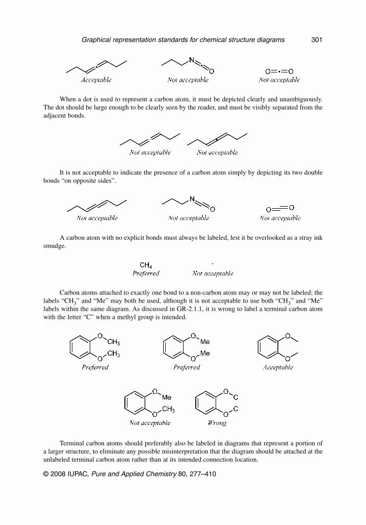
When a dot is used to represent a carbon atom, it must be depicted clearly and unambiguously.The dot should be large enough to be clearly seen by the reader, and must be visibly separated from theadjacent bonds.
It is not acceptable to indicate the presence of a carbon atom simply by depicting its two doublebonds “on opposite sides”.
A carbon atom with no explicit bonds must always be labeled, lest it be overlooked as a stray inksmudge.
Carbon atoms attached to exactly one bond to a non-carbon atom may or may not be labeled; thelabels “CH3” and “Me” may both be used, although it is not acceptable to use both “CH3” and “Me”labels within the same diagram. As discussed in GR-2.1.1, it is wrong to label a terminal carbon atomwith the letter “C” when a methyl group is intended.
Terminal carbon atoms should preferably also be labeled in diagrams that represent a portion ofa larger structure, to eliminate any possible misinterpretation that the diagram should be attached at theunlabeled terminal carbon atom rather than at its intended connection location.
© 2008 IUPAC, Pure and Applied Chemistry 80, 277–410
Graphical representation standards for chemical structure diagrams 301

It is acceptable to add labels for terminal carbon atoms connected to unlabeled carbon atoms, butonly when it is possible to do so without overlapping other portions of the diagram.
When ethane, ethene, ethyne, and related molecules are drawn with only one explicit bond, bothterminal carbon atoms must be labeled explicitly to prevent the molecule from being interpreted as astray line or set of lines.
GR-2.1.3 IsotopesIsotopic substitution is indicated by a superscripted mass number appearing directly to the left of an el-ement symbol (it is not possible to represent an isotope of an otherwise unlabeled carbon atom). Themass number should indicate the isotope’s total mass, and should not indicate its deviation from the el-ement’s nominal mass at natural abundance.
J. BRECHER
© 2008 IUPAC, Pure and Applied Chemistry 80, 277–410
302

The hydrogen isotope of mass 2 may also be indicated by the symbol “D”. The hydrogen isotopeof mass 3 may also be indicated by the symbol “T”. However, the symbols “D” and “T” should prefer-ably not be used in diagrams that also include isotopes of elements other than hydrogen.
The creation of atom labels containing multiple isotopes of one element should preferably beavoided, but if such a label cannot be avoided, atoms in natural abundance should be listed first, fol-lowed by other atoms in increasing isotopic mass number. If an atom label contains both deuterium andtritium, the notation style for those isotopes should be used consistently.
Isotopic labeling (partial rather than complete replacement of the atom by its isotope) is indicatedsimilarly, but the isotopically labeled atom should additionally be enclosed in square brackets. Note thatonly the single element symbol should be so enclosed; if there are other elements (including hydrogenatoms) described in the atom label, they should be located outside the brackets.
© 2008 IUPAC, Pure and Applied Chemistry 80, 277–410
Graphical representation standards for chemical structure diagrams 303

GR-2.1.4 Oxidation numbersWhen required, oxidation numbers should be indicated by a superscripted roman numeral (or arabiczero) immediately following the atomic symbol. Oxidation numbers should preferably be omitted whenthe oxidation state is clearly indicated by the remainder of the structure, which is usually the case in di-agrams that are fully specified with explicit bonds.
GR-2.1.5 Positioning of atom labelsAtom labels should be positioned so that all bonds connecting to the atom label point directly at the el-ement symbol of the atom to which they are bonded. The bonds should approach the label closely, butshould not impinge on the actual characters.
For single-character atom labels, the bonds should point to the center of the character.
For multiple-character atom labels, the bonds should usually point to the center of the first letter(or to the center of the last letter for atom labels attached to the left end of a bond).
When the bonding pattern is highly symmetric, the bonds to multiple-character atom labelsshould instead point to the center of the entire symbol.
J. BRECHER
© 2008 IUPAC, Pure and Applied Chemistry 80, 277–410
304
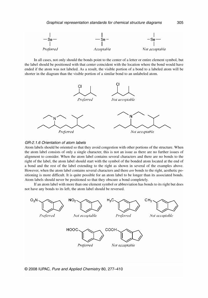
In all cases, not only should the bonds point to the center of a letter or entire element symbol, butthe label should be positioned with that center coincident with the location where the bond would haveended if the atom was not labeled. As a result, the visible portion of a bond to a labeled atom will beshorter in the diagram than the visible portion of a similar bond to an unlabeled atom.
GR-2.1.6 Orientation of atom labelsAtom labels should be oriented so that they avoid congestion with other portions of the structure. Whenthe atom label consists of only a single character, this is not an issue as there are no further issues ofalignment to consider. When the atom label contains several characters and there are no bonds to theright of the label, the atom label should start with the symbol of the bonded atom located at the end ofa bond and the rest of the label extending to the right as shown in several of the examples above.However, when the atom label contains several characters and there are bonds to the right, aesthetic po-sitioning is more difficult. It is quite possible for an atom label to be longer than its associated bonds.Atom labels should never be positioned so that they obscure a bond completely.
If an atom label with more than one element symbol or abbreviation has bonds to its right but doesnot have any bonds to its left, the atom label should be reversed.
© 2008 IUPAC, Pure and Applied Chemistry 80, 277–410
Graphical representation standards for chemical structure diagrams 305
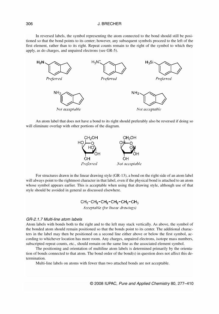
In reversed labels, the symbol representing the atom connected to the bond should still be posi-tioned so that the bond points to its center; however, any subsequent symbols proceed to the left of thefirst element, rather than to its right. Repeat counts remain to the right of the symbol to which theyapply, as do charges, and unpaired electrons (see GR-5).
An atom label that does not have a bond to its right should preferably also be reversed if doing sowill eliminate overlap with other portions of the diagram.
For structures drawn in the linear drawing style (GR-13), a bond on the right side of an atom labelwill always point to the rightmost character in that label, even if the physical bond is attached to an atomwhose symbol appears earlier. This is acceptable when using that drawing style, although use of thatstyle should be avoided in general as discussed elsewhere.
GR-2.1.7 Multi-line atom labelsAtom labels with bonds both to the right and to the left may stack vertically. As above, the symbol ofthe bonded atom should remain positioned so that the bonds point to its center. The additional charac-ters in the label may then be positioned on a second line either above or below the first symbol, ac-cording to whichever location has more room. Any charges, unpaired electrons, isotope mass numbers,subscripted repeat counts, etc., should remain on the same line as the associated element symbol.
The positioning and orientation of multiline atom labels is determined primarily by the orienta-tion of bonds connected to that atom. The bond order of the bond(s) in question does not affect this de-termination.
Multi-line labels on atoms with fewer than two attached bonds are not acceptable.
J. BRECHER
© 2008 IUPAC, Pure and Applied Chemistry 80, 277–410
306

On atoms with two attached bonds, an atom label should be oriented to minimize its overlap withany bonds in the structure. The label may be stacked vertically above or below, or may not be stackedat all depending on the orientation of the two bonds.
In some cases, the label of one atom might overlap with another atom or bond that is not directlyconnected to the first atom. Atom labels should be oriented to minimize overlap with all other objects(including atoms, bonds, charges, annotations, etc.), even those not connected directly.
When overlap can be equally avoided both by multi- and single-line atom labels, the single-linelabels are preferred.
© 2008 IUPAC, Pure and Applied Chemistry 80, 277–410
Graphical representation standards for chemical structure diagrams 307

On atoms with three connected bonds where one of the connected bonds is oriented vertically,overlap can usually be minimized by positioning the atom label on two lines, stacked opposite to theorientation of the vertical bond. A single-line orientation is also acceptable as long as there is little re-sulting overlap.
When an atom with three attached bonds has one of the attached bonds oriented horizontally, thesmallest overlap is generally obtained by a single-line atom label oriented in the opposite horizontal di-rection.
Atom labels containing more than one non-hydrogen element symbol are not acceptable whenthat atom has more than three other bonds. Atom labels containing a non-hydrogen symbol and one ormore hydrogen symbols (or charges or unpaired electrons) may be positioned on multiple lines in anyway that minimizes overlap.
GR-2.2 Structural abbreviations
In addition to element symbols, atom labels may contain substituent abbreviations. The abbreviationsshown in Table II may be used freely. Further definition is unnecessary.
J. BRECHER
© 2008 IUPAC, Pure and Applied Chemistry 80, 277–410
308

Other abbreviations may be used if they are accompanied by a clear explanation of what struc-tural fragment they are intended to represent.
Several structural abbreviations in current usage, as shown below, are identical to an element sym-bol. The use of these and any similar abbreviations should be restricted to situations where they are un-likely to be mistaken for the element symbols. Since these abbreviations conflict only with relativelyuncommon metals, they are fairly safe to use in strictly organic contexts.
Table GR-2.2 Structural abbreviations that can be mistaken for elements.
Abbreviation Element name Abbreviation full name Meaning as abbreviation
Ac Actinium Acetyl
Cm Curium Carboxymethyl
Nb Niobium p-Nitrobenzyl
Np Neptunium p-Nitrophenyl
Pr Praseodymium Propyl
© 2008 IUPAC, Pure and Applied Chemistry 80, 277–410
Graphical representation standards for chemical structure diagrams 309

Other than the abbreviations listed in Table GR-2.2, it is not acceptable to create new abbrevia-tions with the same text as element symbols, even if those abbreviations are defined. Similarly, it is notacceptable to create new abbreviations with the same text (but different meaning) as other abbreviationsin common use (see Table II).
The abbreviation Bz has historically been used for both benzyl and benzoyl moieties, and it hasbeen the subject of contradictory definitions even in earlier IUPAC recommendations [13,15]. Becauseof that historical disagreement over the meaning of Bz, the use of alternative representations is pre-ferred.
GR-2.2.1 Three-letter amino acid abbreviationsThree-letter amino acid abbreviations—and other abbreviations with two or more distinct points of at-tachment—should also be used with care, because the nickname itself gives no indication of the in-tended attachment order:
J. BRECHER
© 2008 IUPAC, Pure and Applied Chemistry 80, 277–410
310

Abbreviations with two or more attachments will generally have a preferred orientation. In thecase of individual amino acids as above, the N-terminus is always on the left by convention, and theC-terminus is always on the right [16]. Unfortunately, just because a convention exists does not guar-antee that the reader—or the computer—will know and understand it.
Special care is needed when there might be a possibility of interpreting an abbreviation of thissort from the “wrong direction”, such as in the depiction of cyclic peptides. If a cyclic peptide is writ-ten on two lines as in the diagram below and to the right, interpreting the cyclic peptide “clockwise” re-quires that the Pro-Met-Asp segment be interpreted from right to left. Similarly, interpreting the cyclicpeptide “counterclockwise” requires that Gln-Trp-Ala segment be interpreted from right to left. If all ofthe abbreviations are rigorously interpreted with their N-termini on the left, the diagram could also beinterpreted as intending an unusual head-to-head and tail-to-tail coupling of the two three-peptide seg-ments that are individually depicted horizontally. Ambiguity is inevitable with diagrams of that sort, andtherefore they should be avoided. When possible, cyclic peptides should preferably be depicted in a sin-gle line, with the cycle closed by plain bonds (GR-1.5). Such problems are general to any asymmetricabbreviation and not limited to amino acids. Other issues specific to amino acids and peptides are dis-cussed in a separate document [16].
SOFTWARE CAUTION: At the time of writing of this document, few software programs are ableto interpret bent bonds at all, and the authors know of no computer software that is able to fully inter-pret complex cyclic peptides as depicted above. If chemical structure diagrams of cyclic peptides arerequired for use within an electronic environment, the use of bent bonds may indeed be not acceptablein that case, and an alternative diagram may be required that avoids the use of abbreviations with twoor more attachments.
GR-2.2.2 Single-letter abbreviationsThere are many other sets of abbreviations that are used with specific molecule classes. In particular,the use of single-character abbreviations can be extremely confusing. Surely, nobody would interpretBENZENE as anything other than C6H6, but it could be Asx-Glu-Asn-Glx-Glu-Asn-Glu according tothe one-letter system of amino acid nomenclature [16]. The use of single-character abbreviations shouldbe limited to contexts where their intended meaning is clear.
It is acceptable to use the Greek lowercase letter phi (φ) to represent a phenyl group. That abbre-viation has a long history, and ambiguity is unlikely since that letter is rarely used for other purposes inchemical structure diagrams.
© 2008 IUPAC, Pure and Applied Chemistry 80, 277–410
Graphical representation standards for chemical structure diagrams 311

The use of Latin alphabet single-character abbreviations in conjunction with other structural fea-tures (atoms and bonds) is not acceptable; abbreviations of this type are best restricted to running text.If it is absolutely necessary to mix abbreviations with other structural features, abbreviations with morethan one letter should be used instead. The use of the italic letter P is an exception that should not beused outside the scope of biochemical structure diagrams (see GR-0.3).
GR-2.3 Atom labels representing more than one non-hydrogen atom
When clarity is critical and space is not a concern, fully expanded structures (showing an explicit bondbetween every pair of non-hydrogen atoms) are always preferable to structures showing more complexatom labels. However, space often is a concern, particularly when preparing structures for publication.The following recommendations should provide some guidelines for producing complex atom labelsthat are likely to be understood correctly in most circumstances.
GR-2.3.1 General guidelinesAtom labels representing more than one non-hydrogen atom—also sometimes known as “contracted”labels—rely on the fact that many elements have consistent and well-understood bonding patterns. Theelements shown with a dark gray background below are fairly safe to use in contracted labels, with afew exceptions as will be discussed. The elements shown with a light gray background are less safe, asthey all have common forms with several different valence states. The remaining uncolored elementshave highly variable bonding patterns and should not be used in contracted labels, but always drawnwith explicit bonds.
J. BRECHER
© 2008 IUPAC, Pure and Applied Chemistry 80, 277–410
312

GR-2.3.2 Contracted labels with more than one explicit bondContracted atom labels may have at most two bonds, one extending horizontally from each of the firstand last characters in the label. Such labels should be read from left to right, with the first element con-nected to the leftmost bond and the last element connected to the rightmost bond.
It is not acceptable to create contracted labels with more than one bond attached to the first (orlast) element within the label, or to create contracted labels with bonds connected to an interior elementwithin the label.
GR-2.3.3 Orientation of symbols within contracted labelsContracted atom labels attached to only one bond should be read outwards from that bond, usually fromleft to right if the bond is on the left of the label. If the bond is instead attached to the right of the label,
© 2008 IUPAC, Pure and Applied Chemistry 80, 277–410
Graphical representation standards for chemical structure diagrams 313

the label will normally be read from right to left, but ambiguities can result. Accordingly, contracted la-bels with a bond on the right should be avoided except for simple cases, usually limited to relativelysmall labels containing four or fewer combined element symbols and abbreviations. Contracted labelswith a single bond attached to an interior atom or with multiple connecting bonds should always be readfrom left to right, but these also are prone to ambiguity and should similarly be avoided except for sim-ple cases.
Relatively long labels with bonds to the rightmost character should be avoided, since their inter-pretation can be extremely difficult. The following two cases demonstrate this problem. Although thelabels appear superficially very similar, the first must be interpreted from left to right, and would rep-resent an acetoxymethyl substituent, while the second must be interpreted from right to left, and wouldrepresent a methyl ester of a carboxylic acid. (The use of parentheses to indicate branching explicitly,as discussed in GR-2.3.5, can be used to reduce some of the potential for ambiguity.)
In extreme cases, a single label could represent different structural fragments depending onwhether it was interpreted from right to left or from left to right.
J. BRECHER
© 2008 IUPAC, Pure and Applied Chemistry 80, 277–410
314
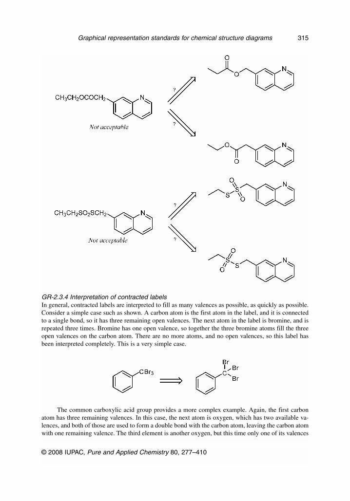
GR-2.3.4 Interpretation of contracted labelsIn general, contracted labels are interpreted to fill as many valences as possible, as quickly as possible.Consider a simple case such as shown. A carbon atom is the first atom in the label, and it is connectedto a single bond, so it has three remaining open valences. The next atom in the label is bromine, and isrepeated three times. Bromine has one open valence, so together the three bromine atoms fill the threeopen valences on the carbon atom. There are no more atoms, and no open valences, so this label hasbeen interpreted completely. This is a very simple case.
The common carboxylic acid group provides a more complex example. Again, the first carbonatom has three remaining valences. In this case, the next atom is oxygen, which has two available va-lences, and both of those are used to form a double bond with the carbon atom, leaving the carbon atomwith one remaining valence. The third element is another oxygen, but this time only one of its valences
© 2008 IUPAC, Pure and Applied Chemistry 80, 277–410
Graphical representation standards for chemical structure diagrams 315

is used to create a single bond to the carbon atom. That fills all of the available valences for the carbonatom, but leaves one remaining valence on the oxygen atom, which is in turn filled by the fourth atom,a hydrogen atom.
In the similar case of a peroxide, two valences on the first carbon atom are filled immediately bytwo hydrogen atoms. With only one valence remaining on the carbon atom, the first oxygen atom hasno option but to chain with the second, forming a very different bonding pattern from that of the car-boxylic acid.
Divalent structural fragments may be enclosed in brackets and followed by a repeat count to rep-resent repeating fragments concisely.
As discussed above, a valence-based interpretation of atom labels will be successful only for el-ements with predictable bonding patterns. Some elements, including sulfur, commonly exist in a vari-ety of valences. Contracted labels containing these elements should be avoided, particularly when thoseelement symbols are immediately followed by multiple chalcogen or halogen symbols.
J. BRECHER
© 2008 IUPAC, Pure and Applied Chemistry 80, 277–410
316

When used as part of a larger label, the textual fragments SO2, SeO2, and TeO2 should be usedonly to represent sulfones, selenones, and tellurones, respectively, and should never be used to repre-sent the linear isomers or any other branching form.
Even in the presence of other atoms with variable valence, the CH2 fragment should always beinterpreted as a chaining moiety, even when followed by a repeat count. Structures containing branch-ing methylidene fragments should be drawn with explicit atoms and bonds.
CH2 fragments intended to represent branches should always be indicated with a leading equalssign and enclosed in parentheses as discussed in GR-2.3.5.
© 2008 IUPAC, Pure and Applied Chemistry 80, 277–410
Graphical representation standards for chemical structure diagrams 317

Some very common contracted labels cannot be interpreted with a simple application of valencerules, but also need some implicit charges to be added. A larger list of these labels is shown inTable III.
GR-2.3.5 BranchingSimple branching patterns may be implied by the basic valence rules described above, and do not re-quire special notation. More complex branching may be clarified by placing parentheses around all el-ements within a branch. One valence for the first element within the parentheses is used for connectingthe previous atom outside the parentheses; subsequent atoms within the parenthesized section are thenbound to the first or subsequent atoms, even if an atom outside the parentheses has remaining open va-lences.
J. BRECHER
© 2008 IUPAC, Pure and Applied Chemistry 80, 277–410
318
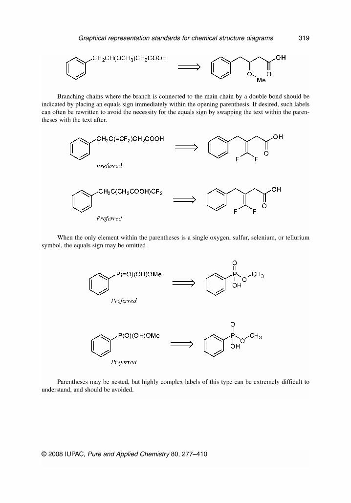
Branching chains where the branch is connected to the main chain by a double bond should beindicated by placing an equals sign immediately within the opening parenthesis. If desired, such labelscan often be rewritten to avoid the necessity for the equals sign by swapping the text within the paren-theses with the text after.
When the only element within the parentheses is a single oxygen, sulfur, selenium, or telluriumsymbol, the equals sign may be omitted
Parentheses may be nested, but highly complex labels of this type can be extremely difficult tounderstand, and should be avoided.
© 2008 IUPAC, Pure and Applied Chemistry 80, 277–410
Graphical representation standards for chemical structure diagrams 319
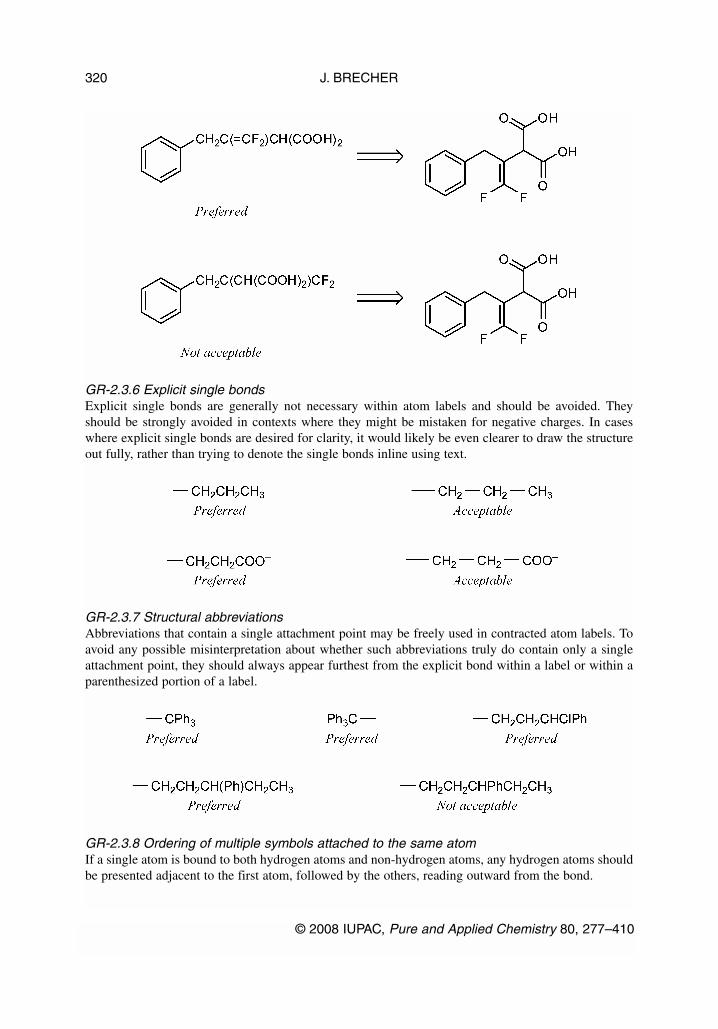
GR-2.3.6 Explicit single bondsExplicit single bonds are generally not necessary within atom labels and should be avoided. Theyshould be strongly avoided in contexts where they might be mistaken for negative charges. In caseswhere explicit single bonds are desired for clarity, it would likely be even clearer to draw the structureout fully, rather than trying to denote the single bonds inline using text.
GR-2.3.7 Structural abbreviationsAbbreviations that contain a single attachment point may be freely used in contracted atom labels. Toavoid any possible misinterpretation about whether such abbreviations truly do contain only a singleattachment point, they should always appear furthest from the explicit bond within a label or within aparenthesized portion of a label.
GR-2.3.8 Ordering of multiple symbols attached to the same atomIf a single atom is bound to both hydrogen atoms and non-hydrogen atoms, any hydrogen atoms shouldbe presented adjacent to the first atom, followed by the others, reading outward from the bond.
J. BRECHER
© 2008 IUPAC, Pure and Applied Chemistry 80, 277–410
320

If more than one single-element symbol or abbreviation is attached to the same non-hydrogenatom, the element symbols should be presented first in alphabetical order (after any hydrogen symbols),followed by the abbreviations in alphabetical order, reading outward from the bond.
Fragments containing multiple symbols should appear only after all hydrogen symbols, single-el-ement symbols, and abbreviations, since that arrangement will often avoid the use of parentheses.
GR-2.3.9 Atom labels without explicit connectivityAtom labels are inherently ambiguous when written as simple counts of elements. The reader cannotknow whether one specific isomer was intended, or whether the diagram indicates that the exact isomertruly was not known. Such labels are not acceptable; either the atoms and bonds should be drawn ex-plicitly, or one of the alternative atom label styles discussed above should be used instead.
© 2008 IUPAC, Pure and Applied Chemistry 80, 277–410
Graphical representation standards for chemical structure diagrams 321

GR-2.4 Formulas
Formulas may be considered as atom labels not connected to any bonds. They may be preferred to struc-tural diagrams for simple molecules such as NaCl and MeOH. Formulas should always be interpretedfrom left to right, but otherwise observe restrictions similar to other kinds of atom labels. For organicmolecules with more than one carbon atom, structure diagrams with explicit atoms and bonds are pre-ferred over formulas. Guidelines for producing and using formulas of inorganic molecules are presentedin ref. [13].
GR-3. ORIENTATION OF STRUCTURES
When considering the guidelines to follow for the orientation of chemical structures, perhaps the mostimportant thing to keep in mind is that, as far as chemical meaning is concerned, they do not matter.With a single exception in the case of Fischer projections [17,18], simple rotation of a chemical struc-ture within the plane of the diagram will never affect its chemical meaning. Flipping a portion of a struc-ture requires a corresponding adjustment of stereobonds (solid wedged bonds must be changed tohashed wedged bonds, etc.), but changes nothing otherwise. In terms of chemical meaning, the orien-tation of structures is irrelevant.
On the other hand, practicing chemists generally have an idea of the orientations they expect. Thisis especially true for various classes of biological molecules, and particularly for those with multiplestereogenic centers, but it is an issue for all structures to some extent. Although benzene could be drawnin any orientation (as shown at right, above), most chemists would expect to see it with “points up anddown” or possibly with “points left and right” (left and center structures above, respectively). So, se-lecting a reasonable orientation for chemical structures serves only to present chemical information ina way that is most convenient and least surprising to other chemists. That is still important, for sure, butnowhere near as important as making sure that the chemical structure itself is as accurate as possible,whatever its orientation.
J. BRECHER
© 2008 IUPAC, Pure and Applied Chemistry 80, 277–410
322
Selection of a reasonable orientation is an art form even more so than other aspects of structurerepresentation. It is therefore worth emphasizing, again, that these guidelines are only guidelines. Theyare provided so that an author who wants to “follow the rules” has some rules to follow. They are notexpected to be comprehensive for all possible chemical structures, and they are certainly not intendedto be definitive. If you have a structure that you think looks better if these guidelines are not followed,then by all means draw it in the way that looks best to you. There is absolutely no problem with that.
It should also be considered that the recommendations that follow are for the depiction of chem-ical structure diagrams in isolation. That is, as discussed in GR-0.1, they are for use when answeringthe question, “What is the chemical structure of X?” When depicting relationships between molecules,it is entirely appropriate to modify the orientation of the individual diagrams so that they accurately de-scribe whatever relationships are being depicted. In an extreme example, ligands participating within aninorganic complex must certainly be oriented to demonstrate their role within that complex, regardlessof their preferred orientation in unbound form. Similarly, reaction diagrams will often be arranged toemphasize the movement of electrons during the reaction [19]. To accomplish that, the individual reac-tion components may be depicted in orientations that are far from what would be preferred in isolation.When chemical structure diagrams are used in larger contexts, the diagrams may need to be modifiedappropriately.
GR-3.1 General guidelines for orientation of structures
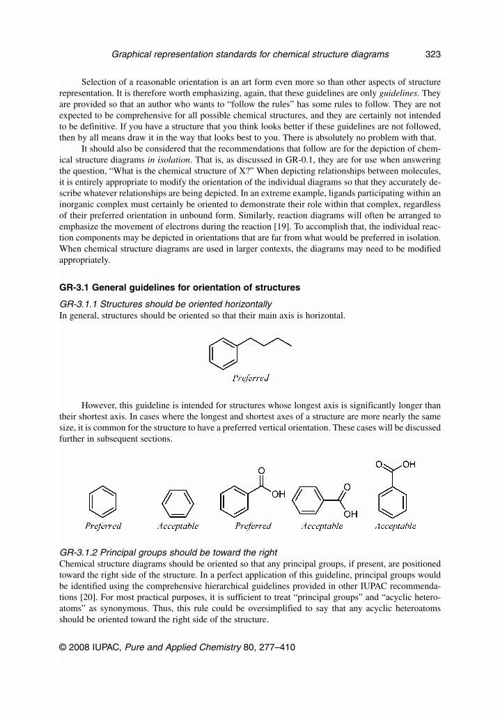
GR-3.1.1 Structures should be oriented horizontallyIn general, structures should be oriented so that their main axis is horizontal.
However, this guideline is intended for structures whose longest axis is significantly longer thantheir shortest axis. In cases where the longest and shortest axes of a structure are more nearly the samesize, it is common for the structure to have a preferred vertical orientation. These cases will be discussedfurther in subsequent sections.
GR-3.1.2 Principal groups should be toward the rightChemical structure diagrams should be oriented so that any principal groups, if present, are positionedtoward the right side of the structure. In a perfect application of this guideline, principal groups wouldbe identified using the comprehensive hierarchical guidelines provided in other IUPAC recommenda-tions [20]. For most practical purposes, it is sufficient to treat “principal groups” and “acyclic hetero-atoms” as synonymous. Thus, this rule could be oversimplified to say that any acyclic heteroatomsshould be oriented toward the right side of the structure.
© 2008 IUPAC, Pure and Applied Chemistry 80, 277–410
Graphical representation standards for chemical structure diagrams 323

Since systematic numbering starts nearest the principal group(s), this guideline also implies thatstructures should be oriented so that systematic numbering increases from right to left within the struc-ture.
However, organic esters should be oriented so that the parent acid points toward the right, even ifthe ester principal group is positioned toward the overall left of the diagram.
GR-3.1.3 Rings should be toward the bottom-leftIn the absence of a different overriding concern, the principal ring system (see GR-4.2.1) within a struc-ture should be oriented toward the bottom-left of the structure.
GR-3.2 Orientation of chains
There are two main styles for depicting acyclic structures and fragments, the “chain” (or “zigzag”)form, and the “linear” form. Since it is possible to use the linear form only for relatively simple struc-tures, the chain form is more generally useful. The linear form, however, remains acceptable for anystructure to which it is suited. Most issues that apply to the chain form would also apply to the linearform. Other issues specific to the linear form are discussed in GR-13.
GR-3.2.1 Structures should be oriented horizontallyAs stated in the general overview, all structures should be oriented horizontally when possible. This isalways possible for the main chain in an acyclic structure.
J. BRECHER
© 2008 IUPAC, Pure and Applied Chemistry 80, 277–410
324

When orienting a chain horizontally, care should be taken to consider the chain as a whole. Inmany cases, a horizontal chain implies that the chain’s first bond be oriented 30° from horizontal, butthe recommendation is for the chain itself to be horizontal, even if that means that the individual bondswithin the chain are not aligned at multiples of 30°.
GR-3.2.2 Branching double bonds should be upwardsA doubly bonded substituent that branches from a horizontal chain should preferentially be positionedabove the chain rather than below it, even if that requires a change in the “zigzag direction” of the chain.This is most commonly seen in ketones, carboxylic acids, and related molecules.
GR-3.3 Depiction of rings
Unlike chains, which typically have two possible conformations at every non-terminal atom, rings havefewer degrees of freedom. It is especially important to depict rings correctly, since readers will oftenhave firm expectations of how a ring should appear.
© 2008 IUPAC, Pure and Applied Chemistry 80, 277–410
Graphical representation standards for chemical structure diagrams 325

GR-3.3.1 Simple rings with eight or fewer ring atomsIsolated rings that do not share any atoms with other rings should be depicted as regular polygons ifthey contain eight or fewer atoms within the ring.
As discussed in the recommendations for graphical representation of stereochemical configura-tion [6], Haworth projections are also preferred, although only for the depiction of carbohydrates andstructurally related molecules. Similarly, other sorts of perspective diagrams are preferred when dis-cussing conformation (since there is no other reasonable way to depict boat and chair forms, etc.) andacceptable when it is desired to emphasize configuration.
GR-3.3.2 Simple rings with nine or more ring atomsIsolated rings with at least nine atoms within the ring should be drawn with reentrant bond angles(“puckered”), as tracing the boundary of a properly depicted fused ring system (see GR-3.3.3).
One goal of depiction of these large rings is to preserve standard bond lengths and angles as muchas possible. Ideally, every pair of standard-length bonds should be separated by 120°, but that is not eventheoretically possible for rings with an odd number of atoms. If it is not possible to preserve 120° an-gles, it is acceptable to use other angles that are present in regular pentagons (108°), heptagons (ap-proximately 129°), and octagons (135°).
Some examples are shown, for rings with 9 through 14 atoms. Note that there will often be morethan one reasonable conformation as the rings get larger. For each ring size, the first diagram shows thepreferred conformation for rings without any restrictions, such as the unsubstituted CnH2n cycloalkanes.In the presence of substituents or double bonds within the ring, it may be necessary to select one of theother conformations to avoid overlap or to preserve double-bond configuration.
J. BRECHER
© 2008 IUPAC, Pure and Applied Chemistry 80, 277–410
326
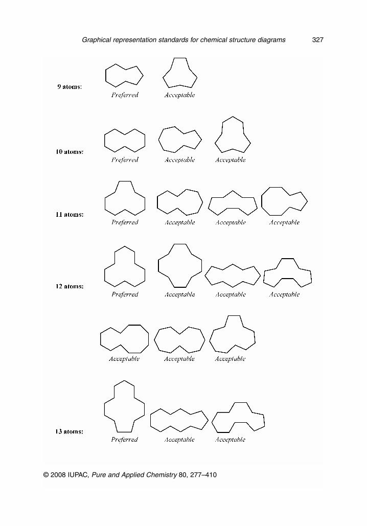
© 2008 IUPAC, Pure and Applied Chemistry 80, 277–410
Graphical representation standards for chemical structure diagrams 327

Many factors need to be considered and balanced when choosing which conformation to usewhen depicting any given large ring. The conformations described as preferred in the Table immedi-ately above are not necessarily preferred for molecules other than the specific unadorned cycloalkanesdepicted.
The single most important factor to consider when selecting a conformation is the configurationof any double bonds within the ring. Each double bond must be depicted in the correct stereochemicalconfiguration without exception.
The positioning of substituents on a large ring should also be considered, although the position-ing of substituents is less important than the preservation of double-bond stereochemistry and the posi-tioning of fused rings. While it is preferable to have as many substituent atoms outside the ring as pos-
J. BRECHER
© 2008 IUPAC, Pure and Applied Chemistry 80, 277–410
328

sible, it is acceptable to have some substituents inside the ring if they can be positioned without distor-tion or overlap.
It is entirely possible to have more than one reasonable conformation of a large ring, one withmore substituents inside and one with fewer. The pair of diagrams shown might be used to illustrate dif-ferent modes where the macrocycle might form a complex with an ion via the nitrogen atoms in the ringor via the oxygen atoms.
© 2008 IUPAC, Pure and Applied Chemistry 80, 277–410
Graphical representation standards for chemical structure diagrams 329
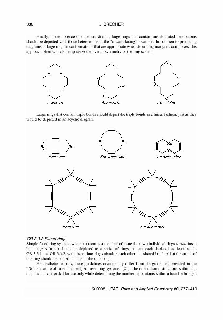
Finally, in the absence of other constraints, large rings that contain unsubstituted heteroatomsshould be depicted with those heteroatoms at the “inward-facing” locations. In addition to producingdiagrams of large rings in conformations that are appropriate when describing inorganic complexes, thisapproach often will also emphasize the overall symmetry of the ring system.
Large rings that contain triple bonds should depict the triple bonds in a linear fashion, just as theywould be depicted in an acyclic diagram.
GR-3.3.3 Fused ringsSimple fused ring systems where no atom is a member of more than two individual rings (ortho-fusedbut not peri-fused) should be depicted as a series of rings that are each depicted as described inGR-3.3.1 and GR-3.3.2, with the various rings abutting each other at a shared bond. All of the atoms ofone ring should be placed outside of the other ring.
For aesthetic reasons, these guidelines occasionally differ from the guidelines provided in the“Nomenclature of fused and bridged fused ring systems” [21]. The orientation instructions within thatdocument are intended for use only while determining the numbering of atoms within a fused or bridged
J. BRECHER
© 2008 IUPAC, Pure and Applied Chemistry 80, 277–410
330

fused ring system. The guidelines presented here should be used when depicting that ring system afterits atoms have been numbered.
When three six-membered rings are fused so that each pair shares a bond and they all share onecommon atom, it is also possible to abut the rings without distortion.
Three-way fusions involving rings of other than six atoms will generally require distortion of oneor more of the ring systems. When the ring system is symmetric, distortions that preserve the symmetryare preferred to those that break it. Otherwise, it is preferable to leave as many six-membered ringsundistorted as possible.
© 2008 IUPAC, Pure and Applied Chemistry 80, 277–410
Graphical representation standards for chemical structure diagrams 331
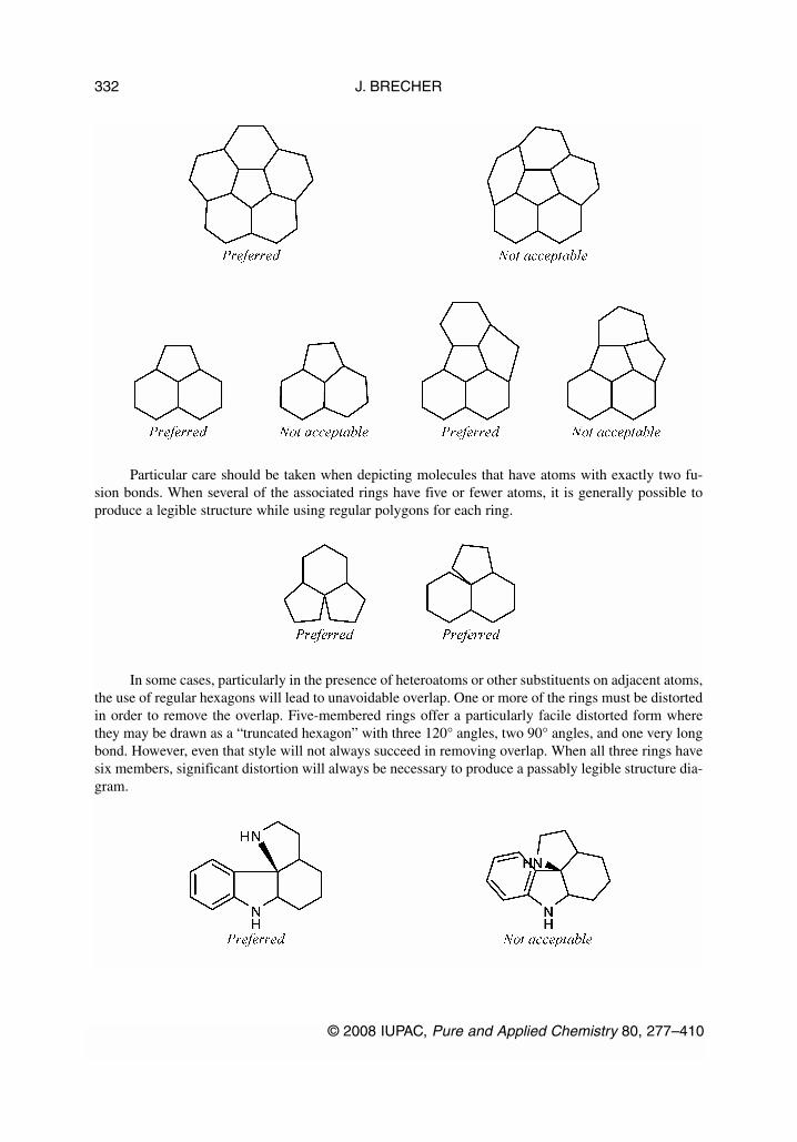
Particular care should be taken when depicting molecules that have atoms with exactly two fu-sion bonds. When several of the associated rings have five or fewer atoms, it is generally possible toproduce a legible structure while using regular polygons for each ring.
In some cases, particularly in the presence of heteroatoms or other substituents on adjacent atoms,the use of regular hexagons will lead to unavoidable overlap. One or more of the rings must be distortedin order to remove the overlap. Five-membered rings offer a particularly facile distorted form wherethey may be drawn as a “truncated hexagon” with three 120° angles, two 90° angles, and one very longbond. However, even that style will not always succeed in removing overlap. When all three rings havesix members, significant distortion will always be necessary to produce a passably legible structure dia-gram.
J. BRECHER
© 2008 IUPAC, Pure and Applied Chemistry 80, 277–410
332

The shape of a large ring that is part of a fused ring system may be influenced by other compo-nents of that system, requiring a shape or orientation for the larger ring that would not be preferred if itwas not fused (see GR-3.3.2). Rings that share a single fusion bond should preferably be arranged sothat the fusion bond is in a “cis-like” configuration relative to the larger ring. This is especially impor-tant in situations where the combination of ring sizes involved in the fusion would result in bonds thatexactly overlap if the larger ring were in a “trans-like” configuration.
In some cases, the most legible depiction of a fused ring system may even require the positioningof some substituents within the larger ring.
© 2008 IUPAC, Pure and Applied Chemistry 80, 277–410
Graphical representation standards for chemical structure diagrams 333
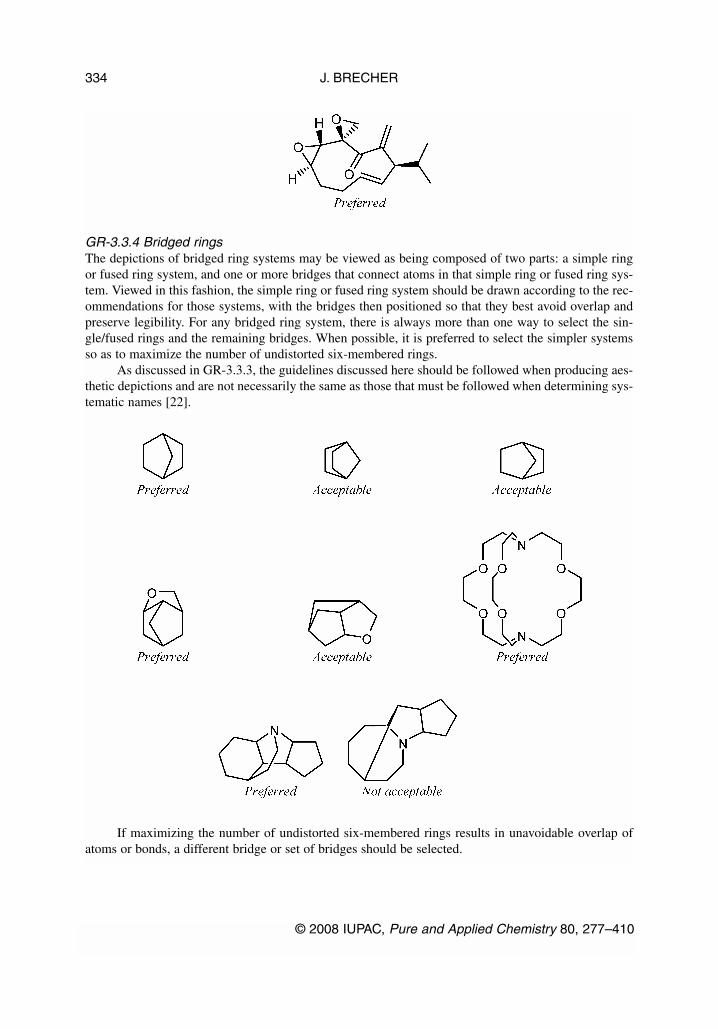
GR-3.3.4 Bridged ringsThe depictions of bridged ring systems may be viewed as being composed of two parts: a simple ringor fused ring system, and one or more bridges that connect atoms in that simple ring or fused ring sys-tem. Viewed in this fashion, the simple ring or fused ring system should be drawn according to the rec-ommendations for those systems, with the bridges then positioned so that they best avoid overlap andpreserve legibility. For any bridged ring system, there is always more than one way to select the sin-gle/fused rings and the remaining bridges. When possible, it is preferred to select the simpler systemsso as to maximize the number of undistorted six-membered rings.
As discussed in GR-3.3.3, the guidelines discussed here should be followed when producing aes-thetic depictions and are not necessarily the same as those that must be followed when determining sys-tematic names [22].
If maximizing the number of undistorted six-membered rings results in unavoidable overlap ofatoms or bonds, a different bridge or set of bridges should be selected.
J. BRECHER
© 2008 IUPAC, Pure and Applied Chemistry 80, 277–410
334

Authors should be especially mindful of diagrams that produce three collinear atoms with an ad-ditional bond between the first and last atoms of the three. Molecules of this sort are thankfully rare,but typically require extensive distortion in order to produce an understandable diagram.
In extreme cases, a perspective-based depiction may be the only reasonable way to produce anunderstandable diagram. Molecules that approximate regular polyhedra are especially well suited to aperspective-based depiction.
It is preferable to minimize the number of substituents on bridges, although generally not at theexpense of maintaining undistorted six-membered rings.
© 2008 IUPAC, Pure and Applied Chemistry 80, 277–410
Graphical representation standards for chemical structure diagrams 335

In extreme cases, significant distortion of a bridge may be necessary to reduce overlap enough toproduce an understandable diagram
When three or more simple rings share one bond, it is critically important that all three rings re-main visible without obscuring each other. Occasionally, it may be possible to “nest” rings of differentsizes inside each other without distortion. However, some sort of distortion will always be necessary ifat least three of the rings are of the same size.
SOFTWARE CAUTION: Although one hopes that no human would create diagrams with ringsthat exactly overlap in this manner, such overlap is regrettably common in diagrams produced by com-puter software. Authors are always encouraged to review the output of computer programs carefully,lest any atoms or bonds be completely obscured and the apparent meaning of a diagram be other thanwas intended.
J. BRECHER
© 2008 IUPAC, Pure and Applied Chemistry 80, 277–410
336

In bridged ring systems that contain large rings (GR-3.3.2) and additional fused rings (GR-3.3.3),the various requirements of those systems must all be balanced to produce the best overall depiction.The shape of a large ring that is part of a bridged ring system will often be influenced by other compo-nents of that system, often requiring a shape for the larger ring that would not be preferred if it was notbridged (see GR-3.3.2).
Rings that share two bonds should preferably be arranged to minimize the distortion of both rings.Typically, that will result in both shared bonds being trans-like relative to the larger ring.
Rings that share three fusion bonds should be arranged so that the outer two shared bonds aretrans-like relative to the larger ring while the central shared bond is cis-like relative to both.
It may be necessary to depict fused rings on a “trans-like” fusion bond as long as the combina-tion of the bond angles in the two rings allows such positioning without overlap.
© 2008 IUPAC, Pure and Applied Chemistry 80, 277–410
Graphical representation standards for chemical structure diagrams 337
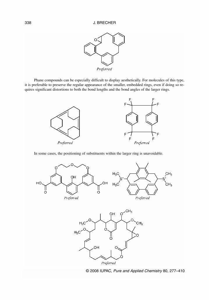
Phane compounds can be especially difficult to display aesthetically. For molecules of this type,it is preferable to preserve the regular appearance of the smaller, embedded rings, even if doing so re-quires significant distortions to both the bond lengths and the bond angles of the larger rings.
In some cases, the positioning of substituents within the larger ring is unavoidable.
J. BRECHER
© 2008 IUPAC, Pure and Applied Chemistry 80, 277–410
338

GR-3.4 Orientation of rings
When present, ring systems generally serve as the focal point of a chemical structure. Although thereare exceptions, the “principal” ring system is normally positioned in a preferred orientation, and onlythen are all other substituents positioned accordingly.
GR-3.4.1 Selection of the principal ring systemIn many cases—and particularly when there is only one ring system in the entire structure—selectionof the principal ring system is obvious. In more complicated cases, there is substantial flexibility.Although it is always acceptable to select the principal ring system according to the hierarchy describedin the “Nomenclature of fused and bridged fused ring systems” guidelines [21], rigorous application ofthat hierarchy is unnecessary if the main intention is simply to produce an aesthetic diagram. For mostpractical purposes, it is sufficient to select the principal ring system as
• the one that has the largest number of fused rings;• if there is more than one such system, the one with the largest individual rings (eight-membered,
seven-membered, etc.);• if there is still more than one system, the one with the greatest unsaturation; or• if there is still more than one system, the one with the greatest number of heteroatoms
Those four guidelines are a tremendous oversimplification of the full Fused Ring Systems guide-lines, but they will serve most purposes. Phrased differently, the principal ring system may be consid-ered to be “the ring system that seems most important”. Those guidelines will usually produce the ringsystem that most chemists would consider to be “most important” in a structure, but they need not befollowed rigorously, either. In a discussion of several related molecules, for example, it would be rea-sonable to select a single ring system to be considered as “most important” across the collection. So thesingle-ring benzoic acid might well be considered “more important” than a two-ring naphthyl group ina collection of structures that consist of 2-fluorobenzoic acid, 2-chlorobenzoic acid, 2-bromobenzoicacid, 2-hydroxybenzoic acid, 2-cyclohexylbenzoic acid, 2-(2-naphthyl)benzoic acid, etc.
Nor should the simple presence of a ring be an absolute determining factor for the orientation ofa structure! In a structure with a chain that is large compared to the size of the largest ring system, it isoften reasonable to treat the chain as the principal system for orienting the structure, and allow thering(s) to be drawn as simple substitutents once the main chain is positioned.
© 2008 IUPAC, Pure and Applied Chemistry 80, 277–410
Graphical representation standards for chemical structure diagrams 339

GR-3.4.2 Orientation of principal ring systemIf the structure features a ring system that may be reasonably treated as a principal ring, that ring shouldbe presented in its preferred orientation. Isolated, non-fused rings of 3, 4, 5, 7, or 8 atoms should pref-erentially be drawn with a horizontal bond at the bottom of the ring or the top of the ring. Isolated, non-fused six-membered rings should preferentially be drawn with a vertical bond at the left of the ring.
If an alternative orientation is required for some specific purpose (e.g., to emphasize symmetry,or to maximize the number of horizontal substituents), it is acceptable to orient rings of eight or feweratoms so that an atom is located at the extreme left or right of the horizontal centerline of the ring.
Rings with nine or more members should be treated analogously to the corresponding fused ringsystem for selection of preferred orientation.
J. BRECHER
© 2008 IUPAC, Pure and Applied Chemistry 80, 277–410
340
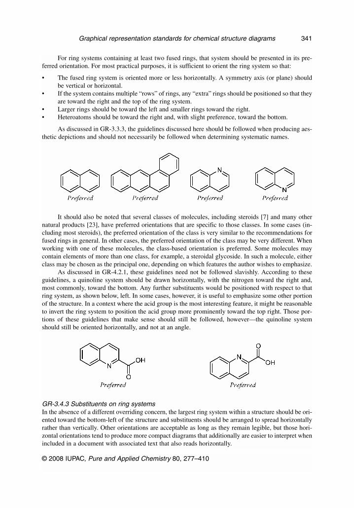
For ring systems containing at least two fused rings, that system should be presented in its pre-ferred orientation. For most practical purposes, it is sufficient to orient the ring system so that:
• The fused ring system is oriented more or less horizontally. A symmetry axis (or plane) shouldbe vertical or horizontal.
• If the system contains multiple “rows” of rings, any “extra” rings should be positioned so that theyare toward the right and the top of the ring system.
• Larger rings should be toward the left and smaller rings toward the right.• Heteroatoms should be toward the right and, with slight preference, toward the bottom.
As discussed in GR-3.3.3, the guidelines discussed here should be followed when producing aes-thetic depictions and should not necessarily be followed when determining systematic names.
It should also be noted that several classes of molecules, including steroids [7] and many othernatural products [23], have preferred orientations that are specific to those classes. In some cases (in-cluding most steroids), the preferred orientation of the class is very similar to the recommendations forfused rings in general. In other cases, the preferred orientation of the class may be very different. Whenworking with one of these molecules, the class-based orientation is preferred. Some molecules maycontain elements of more than one class, for example, a steroidal glycoside. In such a molecule, eitherclass may be chosen as the principal one, depending on which features the author wishes to emphasize.
As discussed in GR-4.2.1, these guidelines need not be followed slavishly. According to theseguidelines, a quinoline system should be drawn horizontally, with the nitrogen toward the right and,most commonly, toward the bottom. Any further substituents would be positioned with respect to thatring system, as shown below, left. In some cases, however, it is useful to emphasize some other portionof the structure. In a context where the acid group is the most interesting feature, it might be reasonableto invert the ring system to position the acid group more prominently toward the top right. Those por-tions of these guidelines that make sense should still be followed, however—the quinoline systemshould still be oriented horizontally, and not at an angle.
GR-3.4.3 Substituents on ring systemsIn the absence of a different overriding concern, the largest ring system within a structure should be ori-ented toward the bottom-left of the structure and substituents should be arranged to spread horizontallyrather than vertically. Other orientations are acceptable as long as they remain legible, but those hori-zontal orientations tend to produce more compact diagrams that additionally are easier to interpret whenincluded in a document with associated text that also reads horizontally.
© 2008 IUPAC, Pure and Applied Chemistry 80, 277–410
Graphical representation standards for chemical structure diagrams 341

GR-3.5 Positioning of double bonds in rings
In the general context of structure-orientation issues, the positioning of double bonds in rings is a minorissue, far less important than the positioning of the rings themselves in relation to other portions of thestructure. Still, there can be a question of positioning of double bonds in rings with highly symmetricsubstituents (or with no substituents at all). Also, there is always a question of the cyclic positioning ofdouble bonds within ring systems with the maximum number of non-cumulative double bonds (“man-cude” ring systems), including aromatic systems. The placement of the two lines composing a doublebond relative to each other is discussed in GR-1.10.4.
GR-3.5.1 Positioning of isolated double bondsDouble bonds should be positioned toward the left (and secondarily toward the top) of a ring.
However, the positioning of double bonds is of less concern than the positioning of fused ring sys-tems and of substituents. For example, a fused ring system should be oriented horizontally even if doingso will position a double bond further rightward than would otherwise be possible.
J. BRECHER
© 2008 IUPAC, Pure and Applied Chemistry 80, 277–410
342

GR-3.5.2 Alternating double bonds may be in either resonance formIn delocalized single-ring systems containing alternating single and double bonds, the bonds may bedrawn in either of two resonance forms, both of which are equally preferred.
In highly symmetrical structures, it is preferable for the double bonds within aromatic systems tobe drawn in a symmetrical fashion as well.
GR-3.6 Structural classes with standard orientations
Several classes of molecules—and especially several classes of biochemical molecules—are tradition-ally drawn using styles that are specific to those classes. Drawing styles for those classes are illustratedwithin the documentation for each of those classes:
• amino acids [16]• carbohydrates [15]• steroids [7]• tetrapyrroles [24]• carotenoids [25]• other natural products [23]• polymers [26,27]
GR-4. POSITIONING OF SUBSTITUENTS
Beyond the overall orientation of structure diagrams, the relative positioning of substituents within a di-agram also influences how that diagram is understood by the reader. Preservation of legibility and re-duction of ambiguity continue to be of critical importance here, as in other areas of graphical represen-tation.
© 2008 IUPAC, Pure and Applied Chemistry 80, 277–410
Graphical representation standards for chemical structure diagrams 343
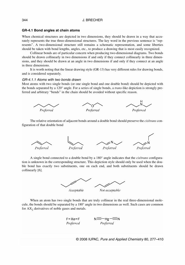
GR-4.1 Bond angles at chain atoms
When chemical structures are depicted in two dimensions, they should be drawn in a way that accu-rately represents the true three-dimensional structures. The key word in the previous sentence is “rep-resents”. A two-dimensional structure still remains a schematic representation, and some libertiesshould be taken with bond lengths, angles, etc., to produce a drawing that is most easily recognized.
Collinear bonds are of particular concern when producing two-dimensional diagrams. Two bondsshould be drawn collinearly in two dimensions if and only if they connect collinearly in three dimen-sions, and they should be drawn at an angle in two dimensions if and only if they connect at an anglein three dimensions.
It is worth noting that the linear drawing style (GR-13) has very different rules for drawing bonds,and is considered separately.
GR-4.1.1 Atoms with two bonds drawnMost atoms with two single bonds (or one single bond and one double bond) should be depicted withthe bonds separated by a 120° angle. For a series of single bonds, a trans-like depiction is strongly pre-ferred and arbitrary “bends” in the chain should be avoided without specific reason.
The relative orientation of adjacent bonds around a double bond should preserve the cis/trans con-figuration of that double bond
A single bond connected to a double bond by a 180° angle indicates that the cis/trans configura-tion is unknown in the corresponding structure. This depiction style should only be used when the dou-ble bond has exactly two substituents, one on each end, and both substituents should be drawncollinearly [6].
When an atom has two single bonds that are truly collinear in the real three-dimensional mole-cule, the bonds should be separated by a 180° angle in two dimensions as well. Such cases are commonfor AX2 derivatives of noble gases and metals.
J. BRECHER
© 2008 IUPAC, Pure and Applied Chemistry 80, 277–410
344

Atoms that are isoelectronic with carbon and bearing two double bonds (or one single bond andone triple bond) should be drawn with the bonds separated by a 180° angle. As discussed in GR-2.1.2,any carbon atom with two double bonds should always be explicitly labeled, to remove the possibilityof the two bonds being misinterpreted as one long bond.
Carbon atoms connected to two heteroatoms by one single bond and one triple bond are equallypreferred with or without explicit labeling of the central carbon atom.
Again, some rare cases exist where an atom with two double bonds should not have those bondsarranged collinearly, but that is limited to atoms with electronic structures other than that of carbon.
GR-4.1.2 Atoms with three bonds drawnAtoms with three bonds drawn should almost always be depicted with three equal 120° angles separat-ing the bonds. In this context, a double bond is considered as one “bond”, not two, and similarly for atriple bond.
© 2008 IUPAC, Pure and Applied Chemistry 80, 277–410
Graphical representation standards for chemical structure diagrams 345

Again, some exceptions exist, principally limited to configurations other than tetrahedral andtrigonal planar. In a T-shaped configuration, for example, the diagram should be drawn with two of thebonds extending vertically above and below the central atom, and the third bond extending to the left.
There are further restrictions for depicting tetrahedral configuration for atoms with three bondsdrawn. Those are discussed elsewhere [6].
GR-4.1.3 Atoms with four bonds drawnAtoms with four bonds may be depicted in several different ways, with a preference among these waysdetermined by context.
When two of the adjacent atoms are each connected to no additional atoms and two of the adja-cent atoms are each connected to at least one additional atom, the four bonds should be separated byone 60° angle, an opposing 120° angle, and two 90° angles. Because of the 120° angle, this style willnot disrupt the orientation of a chain in which it appears. This style also facilitates the depiction of chi-ral centers; the two bonds separated by the 60° angle are marked with a solid wedge and a hashedwedge. If the substituents connected to the two bonds separated by the 60° angle are not identical, thegraphically larger substituent should be on the right for aesthetic purposes.
J. BRECHER
© 2008 IUPAC, Pure and Applied Chemistry 80, 277–410
346

This style should also be used in some cases when three of the adjacent atoms are each connectedto no additional atoms and only one adjacent atom is connected to at least one additional atom. Becausethe 120° angle in this depiction style emphasizes a multiatom chain, it should only be used when an ad-jacent atom is itself acyclic and can be viewed as part of a larger chain with the atom in question. It ismost typically used when exactly one of the terminal substituents is a carbon atom (depicted with a 120°angle separating that substituent from the one with more than one bond) or when two of the terminalsubstituents are not carbon atoms but identical (depicted with a 60° angle separating the identical sub-stituents).
When at least two of an atom’s four bonds are double bonds, it is equally preferred for the atomto be depicted with the four bonds separated by four equal 90° angles.
If exactly two of the bonds in the style are double bonds (as in sulfonyl groups), those two bondsshould usually be drawn opposing each other, with 180° separating them around the central atom. Anexception is made if drawing the two double bonds opposite each other would produce unacceptableoverlap between other portions of the structure that could be avoided by drawing the double bonds ad-jacent.
© 2008 IUPAC, Pure and Applied Chemistry 80, 277–410
Graphical representation standards for chemical structure diagrams 347
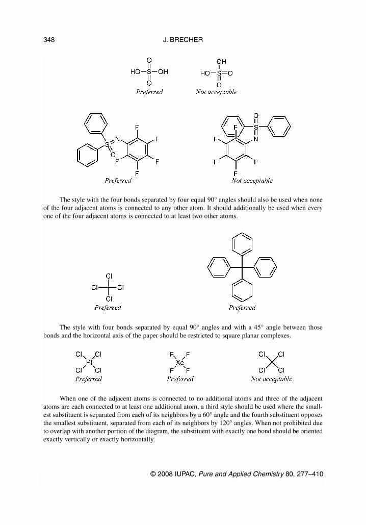
The style with the four bonds separated by four equal 90° angles should also be used when noneof the four adjacent atoms is connected to any other atom. It should additionally be used when everyone of the four adjacent atoms is connected to at least two other atoms.
The style with four bonds separated by equal 90° angles and with a 45° angle between thosebonds and the horizontal axis of the paper should be restricted to square planar complexes.
When one of the adjacent atoms is connected to no additional atoms and three of the adjacentatoms are each connected to at least one additional atom, a third style should be used where the small-est substituent is separated from each of its neighbors by a 60° angle and the fourth substituent opposesthe smallest substituent, separated from each of its neighbors by 120° angles. When not prohibited dueto overlap with another portion of the diagram, the substituent with exactly one bond should be orientedexactly vertically or exactly horizontally.
J. BRECHER
© 2008 IUPAC, Pure and Applied Chemistry 80, 277–410
348
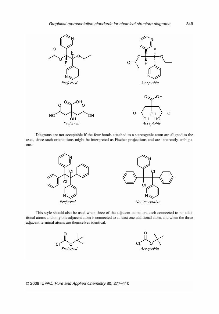
Diagrams are not acceptable if the four bonds attached to a stereogenic atom are aligned to theaxes, since such orientations might be interpreted as Fischer projections and are inherently ambigu-ous.
This style should also be used when three of the adjacent atoms are each connected to no addi-tional atoms and only one adjacent atom is connected to at least one additional atom, and when the threeadjacent terminal atoms are themselves identical.
© 2008 IUPAC, Pure and Applied Chemistry 80, 277–410
Graphical representation standards for chemical structure diagrams 349

A fourth style also may be considered, where the four bonds are separated by one 30° angle, two105° angles, and one 120° angle. This style is occasionally used to emphasize the tetrahedral geometryof phosphates and phosphate esters (and their arsenic and antimony analogs). The style can also be usedin other cases where the tetrahedral geometry is to be emphasized, but it should only be used when twoof the substituents are relatively small, graphically, and those substitutents should be placed on thebonds separated by the 30° angle. This style should always be drawn with one of the other bonds ex-actly vertical or horizontal.
There are further restrictions for depicting tetrahedral configuration for atoms with four bondsdrawn. Those are discussed in the recommendations “Graphical representation of stereochemical con-figuration” [6].
GR-4.1.4 Atoms with more than four bonds drawnAtoms with more than four bonds are rare in organic chemistry, but more common when dealing withinorganic complexes. If no stereochemical significance is assigned to the bonds, they should most com-monly be drawn with one of the bonds directed vertically and the remainder separated by equal angles.If configuration is a concern, the bonds should be drawn in one of the recommended styles for“Graphical representation of stereochemical configuration” [6].
GR-4.1.5 Branching chains should bend outwardUnconstrained secondary chains that branch off a horizontal chain should be oriented, when possible,so that they bend outward from the graphical center of the structure diagram. Besides improving thegeneral aesthetics of the diagram, this recommendation also helps maximize the diagram’s overall hor-izontal arrangement, and in many cases will also assist in emphasizing symmetry as described inGR-3.1.4.
J. BRECHER
© 2008 IUPAC, Pure and Applied Chemistry 80, 277–410
350
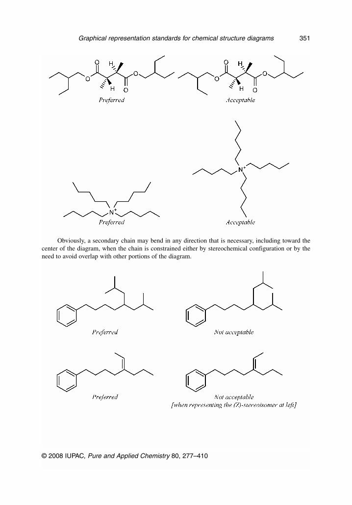
Obviously, a secondary chain may bend in any direction that is necessary, including toward thecenter of the diagram, when the chain is constrained either by stereochemical configuration or by theneed to avoid overlap with other portions of the diagram.
© 2008 IUPAC, Pure and Applied Chemistry 80, 277–410
Graphical representation standards for chemical structure diagrams 351

GR-4.1.6 Double bonds in long chainsIn addition to the styles shown above, there is another style that may be considered when drawing dou-ble bonds in long chains when the double bonds are in a cis configuration relative to the chain. In thisstyle, the double bond is drawn with 150° angles between it and its attached chain bonds rather than theusual 120°. This style serves to preserve the linearity of the chain, and should only be used when thatis desired. It is not acceptable when there is further substitution on the double bond.
J. BRECHER
© 2008 IUPAC, Pure and Applied Chemistry 80, 277–410
352

The similar form with undistorted 120° angles at the double bond and 105° angles to the adjacentchain bonds is acceptable, but not preferred whether or not it has further substituents on the doublebond.
Long chains with triple bonds may be depicted in similar ways.
GR-4.2 Bond angles from rings to substituents
The issues related to bond angles between ring systems and their substituents are very similar to the is-sues related to chain bond angles (GR-4.1). In many cases, bonds from rings to their substituents maybe positioned as if the two neighboring ring bonds described a very short chain, with the substituentsbeing placed as if they were substituents of that chain. There are additionally a few other issues to con-sider that are specific to rings.
GR-4.2.1 Exterior ring atoms with one substituent drawnIn most cases, exterior (non-fusion, non-bridging, non-bridgehead, non-spiro) ring atoms with a singlesubstituent should be drawn so that the substituent bisects the larger angle formed by that atom’s tworing bonds. This is true regardless of the size of the ring or the order of the bond, and also true for non-convex rings.
As above, in cases where bisecting the adjacent bonds would result in a substituent that is within5° of being horizontal, vertical, or at another multiple of 30°, the substituent should preferably be ad-justed so that it is oriented exactly at the nearest such angle. This most commonly happens at fusionsbetween six- and five-membered rings.
© 2008 IUPAC, Pure and Applied Chemistry 80, 277–410
Graphical representation standards for chemical structure diagrams 353
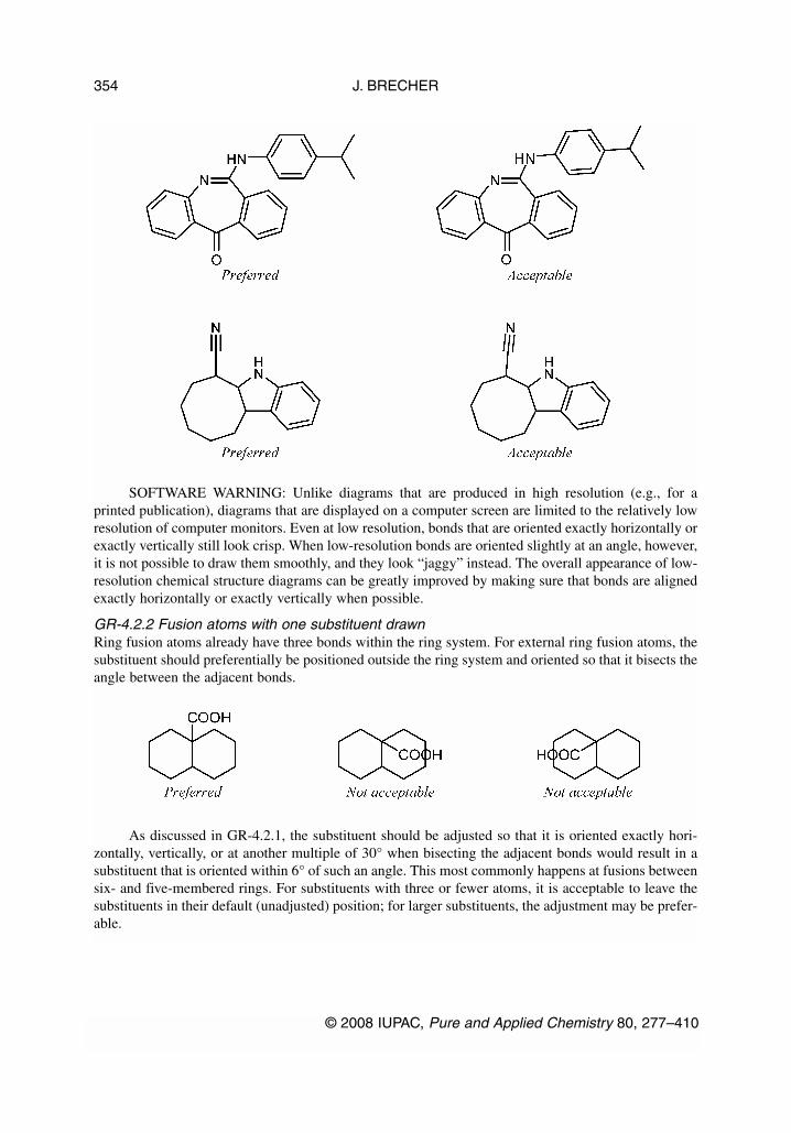
SOFTWARE WARNING: Unlike diagrams that are produced in high resolution (e.g., for aprinted publication), diagrams that are displayed on a computer screen are limited to the relatively lowresolution of computer monitors. Even at low resolution, bonds that are oriented exactly horizontally orexactly vertically still look crisp. When low-resolution bonds are oriented slightly at an angle, however,it is not possible to draw them smoothly, and they look “jaggy” instead. The overall appearance of low-resolution chemical structure diagrams can be greatly improved by making sure that bonds are alignedexactly horizontally or exactly vertically when possible.
GR-4.2.2 Fusion atoms with one substituent drawnRing fusion atoms already have three bonds within the ring system. For external ring fusion atoms, thesubstituent should preferentially be positioned outside the ring system and oriented so that it bisects theangle between the adjacent bonds.
As discussed in GR-4.2.1, the substituent should be adjusted so that it is oriented exactly hori-zontally, vertically, or at another multiple of 30° when bisecting the adjacent bonds would result in asubstituent that is oriented within 6° of such an angle. This most commonly happens at fusions betweensix- and five-membered rings. For substituents with three or fewer atoms, it is acceptable to leave thesubstituents in their default (unadjusted) position; for larger substituents, the adjustment may be prefer-able.
J. BRECHER
© 2008 IUPAC, Pure and Applied Chemistry 80, 277–410
354
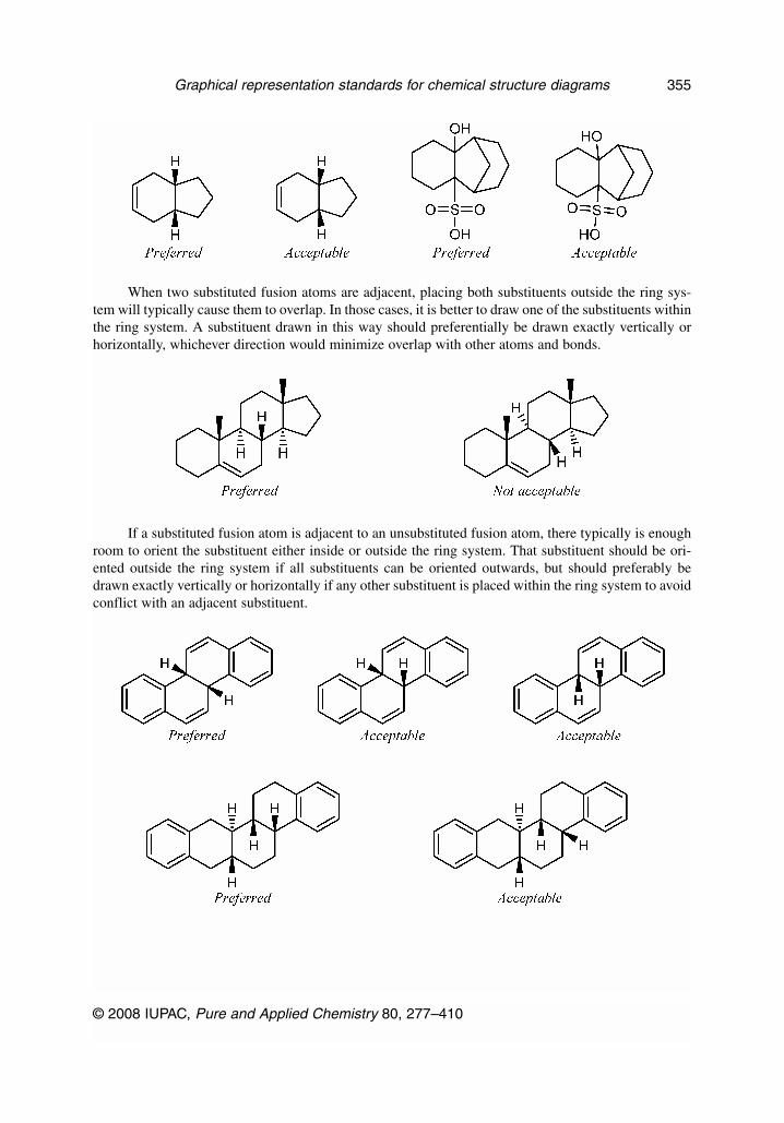
When two substituted fusion atoms are adjacent, placing both substituents outside the ring sys-tem will typically cause them to overlap. In those cases, it is better to draw one of the substituents withinthe ring system. A substituent drawn in this way should preferentially be drawn exactly vertically orhorizontally, whichever direction would minimize overlap with other atoms and bonds.
If a substituted fusion atom is adjacent to an unsubstituted fusion atom, there typically is enoughroom to orient the substituent either inside or outside the ring system. That substituent should be ori-ented outside the ring system if all substituents can be oriented outwards, but should preferably bedrawn exactly vertically or horizontally if any other substituent is placed within the ring system to avoidconflict with an adjacent substituent.
© 2008 IUPAC, Pure and Applied Chemistry 80, 277–410
Graphical representation standards for chemical structure diagrams 355

Small substituents on the C-8 and C-9 atoms of steroids should be drawn within the ring systemin this fashion even if there are no substituents on the adjacent fusion atoms C-10 and C-14. Certainother natural products [23] also have preferred orientations that place substituents within the ring sys-tem.
A substituent should not be oriented within a ring system when attached to a fusion atom thatlacks any vertical or horizontal fusion bond. The substituent should be oriented outside the ring system,minimizing overlap as best as is possible. Sometimes, it might be possible to reorient the ring systemso that the fusion bonds are vertical; the substituents should certainly be placed vertically if so.
It is not acceptable to orient two substituents within the same ring if the ring has fewer than eightatoms. One or both of the substituents should be oriented outside the ring system, minimizing overlapas best as is possible.
Substituents on interior fusion atoms have no option other than being drawn within the ring sys-tem. As above, such substituents should preferentially be drawn exactly vertically or horizontally, ac-cording to the direction that would minimize overlap with other atoms and bonds.
J. BRECHER
© 2008 IUPAC, Pure and Applied Chemistry 80, 277–410
356
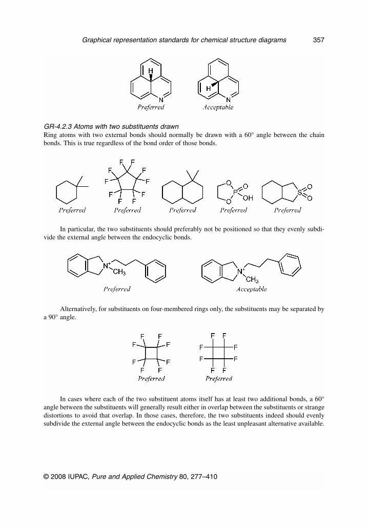
GR-4.2.3 Atoms with two substituents drawnRing atoms with two external bonds should normally be drawn with a 60° angle between the chainbonds. This is true regardless of the bond order of those bonds.
In particular, the two substituents should preferably not be positioned so that they evenly subdi-vide the external angle between the endocyclic bonds.
Alternatively, for substituents on four-membered rings only, the substituents may be separated bya 90° angle.
In cases where each of the two substituent atoms itself has at least two additional bonds, a 60°angle between the substituents will generally result either in overlap between the substituents or strangedistortions to avoid that overlap. In those cases, therefore, the two substituents indeed should evenlysubdivide the external angle between the endocyclic bonds as the least unpleasant alternative available.
© 2008 IUPAC, Pure and Applied Chemistry 80, 277–410
Graphical representation standards for chemical structure diagrams 357

When the two substituents consist of one single-atom substituent and one multi-atom substituent,and when the two substituents are connected to a six-membered ring, the larger substituent should beoriented outside the ring system so that it bisects the angle of the adjacent bonds and the smaller sub-stituent should be oriented so that it bisects an angle adjacent to the larger substituent. When possible,the smaller substituent should also be oriented exactly vertically or exactly horizontally. This drawingstyle helps maximize the number of bonds that are depicted at standard ±30° angles.
The previous recommendation applies only when the two substituents are attached to a six-mem-bered ring. When the two substituents are attached to rings with other than six members, a 60° separa-tion is preferred even when one substituent is large and one is small.
J. BRECHER
© 2008 IUPAC, Pure and Applied Chemistry 80, 277–410
358

When there is a difference between the two sides of the larger substituent, it is preferable to po-sition the smaller substituent on the less crowded side, although it is acceptable to position it on eitherside as long as no overlap results (GR-4.3.1).
If the smaller substituent can be placed on either side of the larger one, it is preferable to orientthe smaller substituent so that it is exactly vertical or exactly horizontal. If neither side achieves that ori-entation, the smaller substituent should be oriented to the right or, if that cannot be achieved either, to-ward the top of the diagram.
© 2008 IUPAC, Pure and Applied Chemistry 80, 277–410
Graphical representation standards for chemical structure diagrams 359
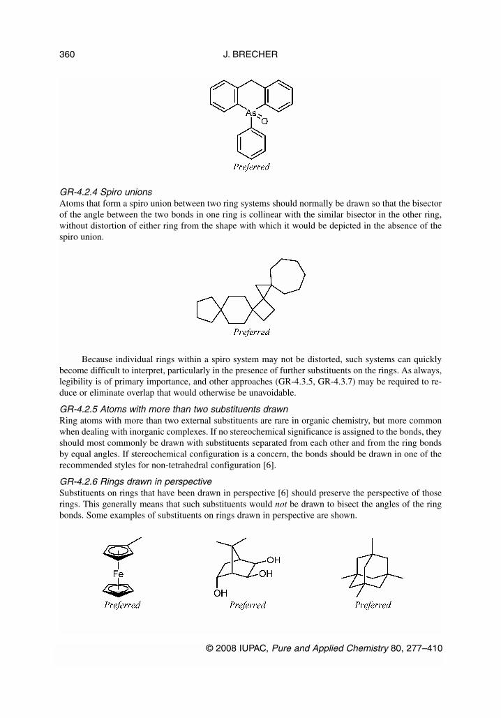
GR-4.2.4 Spiro unionsAtoms that form a spiro union between two ring systems should normally be drawn so that the bisectorof the angle between the two bonds in one ring is collinear with the similar bisector in the other ring,without distortion of either ring from the shape with which it would be depicted in the absence of thespiro union.
Because individual rings within a spiro system may not be distorted, such systems can quicklybecome difficult to interpret, particularly in the presence of further substituents on the rings. As always,legibility is of primary importance, and other approaches (GR-4.3.5, GR-4.3.7) may be required to re-duce or eliminate overlap that would otherwise be unavoidable.
GR-4.2.5 Atoms with more than two substituents drawnRing atoms with more than two external substituents are rare in organic chemistry, but more commonwhen dealing with inorganic complexes. If no stereochemical significance is assigned to the bonds, theyshould most commonly be drawn with substituents separated from each other and from the ring bondsby equal angles. If stereochemical configuration is a concern, the bonds should be drawn in one of therecommended styles for non-tetrahedral configuration [6].
GR-4.2.6 Rings drawn in perspectiveSubstituents on rings that have been drawn in perspective [6] should preserve the perspective of thoserings. This generally means that such substituents would not be drawn to bisect the angles of the ringbonds. Some examples of substituents on rings drawn in perspective are shown.
J. BRECHER
© 2008 IUPAC, Pure and Applied Chemistry 80, 277–410
360

GR-4.2.7 Rings with reentrant bond anglesWhile rings of eight or fewer members are most commonly drawn as convex polygons, larger rings aremore appropriately drawn with some reentrant (non-convex) bond angles (see GR-4.2.2). Wheneverpossible, the ring should be depicted with any substituents positioned on outward-pointing atoms, sothat the substituents themselves point outward according to the recommendations above.
Special care should be taken when representing stereochemical configuration on reentrant bondangles. As discussed in the tetrahedral configuration recommendations [6], it can be extremely difficultand confusing to interpret wedged bonds and hashed wedged bonds in non-standard orientations. Whensuch stereobonds are placed so that they point outward from a reentrant atom, their proper interpreta-tion can be very difficult indeed.
A second diagram, to help clarify this important point even further:
Substituents on reentrant nitrogen atoms are an exception to the general rule. Many large ringscontaining heteroatoms can form complexes, making it desirable to orient all of the heteroatoms in-wards for emphasis. Since stereochemical configuration is not a concern for those monocyclic nitrogenatoms, it is preferable to select a conformation of the ring that does orient the nitrogen atoms inward,even when resulting in substituents on the reentrant atoms.
© 2008 IUPAC, Pure and Applied Chemistry 80, 277–410
Graphical representation standards for chemical structure diagrams 361

The previous exception is limited to cases where there would be a preference to position a sub-stituted atom at a reentrant location even if it was not substituted, and should not be extended more gen-erally. If a large ring is unlikely to form complexes because it contains only a small number of het-eroatoms, it is preferable to depict the ring in a way that avoids substituents on reentrant atoms.
GR-4.3 Avoidance of overlap between substituents
Since the clarity and legibility of a chemical structure diagram must always have priority over all else,it will often be necessary to consider alternatives to the general recommendations presented in GR-4.1and GR-4.2 above. In particular, exact overlap between pairs of atoms or bonds is never acceptable. Itis usually possible to choose among several possible approaches for avoiding such overlap. Thosechoices are discussed below. Furthermore, the following recommendations are presented in the order inwhich they should be considered. The techniques discussed in GR-4.3.2 should not be considered ifoverlap can be avoided completely using the recommendations of GR-4.3.1, and so on, although anysingle diagram may require several techniques to be applied to produce a depiction that is legible over-all.
J. BRECHER
© 2008 IUPAC, Pure and Applied Chemistry 80, 277–410
362

GR-4.3.1 Place a small substituent on the other side of a large substituentFor endocyclic atoms with bonds to one large substituent and one small one, GR-4.2.3 recommends thatthe large substituent be oriented with its bond directly outwards from the ring, and that the small sub-stituent be positioned so that its bond bisects one of the angles adjacent to the bond to the large sub-stituent. There are, however, two such angles. If the position normally recommended by GR-4.2.3 re-sults in overlap that could be avoided by positioning the smaller substituent with its bond along thealternate bisector, then the alternate positioning should be chosen instead.
GR-4.3.2 Rotate about a chain bondRotation about a chain bond is perhaps the single most common and most useful technique for remov-ing overlap between substituents. When there are multiple options for choosing a rotation bond, it ispreferable to rotate along the bond that results in the smallest change to the overall structure diagram.
Rotations around stereogenic double bonds must not be considered.
© 2008 IUPAC, Pure and Applied Chemistry 80, 277–410
Graphical representation standards for chemical structure diagrams 363

GR-4.3.3 Swap neighboring substituentsPositioning two large substituents adjacent to each other may result in overlap. One of those sub-stituents should be swapped with a different adjacent substituent if doing so will produce a more legi-ble diagram.
It is not preferred, however, to swap two substituents when the angles to their adjacent (non-swap-ping) substituents are not equal. In particular, when an atom has substituents separated by 120°, 90°,30°, and 90°, it is not acceptable to swap either of the pairs that are separated by 90°.
J. BRECHER
© 2008 IUPAC, Pure and Applied Chemistry 80, 277–410
364

It is not acceptable to swap substituents if doing so will change the stereochemical configurationof a stereogenic center, such as with a square planar complex.
GR-4.3.4 Bend rings at a spiro unionWith spiro molecules, it is common for structures to be very crowded. It is far better to distort the spirounion angle than it is to have overlapping atoms and bonds in the other parts of the structure.
© 2008 IUPAC, Pure and Applied Chemistry 80, 277–410
Graphical representation standards for chemical structure diagrams 365

GR-4.3.5 Stretch rings at a spiro unionWhen overlap is present as a result of a spiro union and cannot be avoided by distorting the spiro unionangle, it may be necessary to distort the ring systems themselves. When such distortion is necessary, allring systems should be translated outwards from the spiro atom, along with all substituents on thosering systems. This results in lengthening of the bonds to the spiro atom while leaving the other atomsand bonds unaffected.
Inorganic complexes with chelating ligands may be formally considered as having several spiroring systems sharing the central metal atom. Distortion of these systems may similarly be necessary toavoid overlap.
J. BRECHER
© 2008 IUPAC, Pure and Applied Chemistry 80, 277–410
366

GR-4.3.6 Change perspective of planar ringsWhen the bonds of two six-membered rings overlap each other exactly, the simplest method to elimi-nate that overlap may be to change the perspective of those rings, distorting them along the axis of asubstituent bond so that they become narrower and no longer overlap.
Because changing the perspective of a ring may describe a specific hindered biaryl configuration[6], it is not acceptable to change the perspective of planar rings that have additional substituents. Thatis to say, it is not acceptable to depict a molecule in such a way that a hindered rotation is implied incases where the specific stereochemical configuration is not truly known. A different approach, such aschanging the angle at a substituent (GR-4.3.8) is preferred in such cases.
GR-4.3.7 Increase the length of a bondAfter rotation along a bond (GR-4.3.1), increasing the length of a bond is the most useful single tech-nique for avoiding overlap between substituents. Bonds may be lengthened to avoid overlap, but shouldnot be extended further than necessary.
© 2008 IUPAC, Pure and Applied Chemistry 80, 277–410
Graphical representation standards for chemical structure diagrams 367
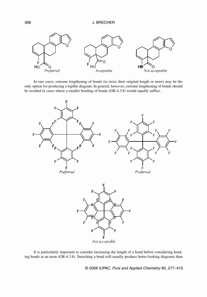
In rare cases, extreme lengthening of bonds (to twice their original length or more) may be theonly option for producing a legible diagram. In general, however, extreme lengthening of bonds shouldbe avoided in cases where a smaller bending of bonds (GR-4.3.8) would equally suffice.
It is particularly important to consider increasing the length of a bond before considering bend-ing bonds at an atom (GR-4.3.8). Stretching a bond will usually produce better-looking diagrams than
J. BRECHER
© 2008 IUPAC, Pure and Applied Chemistry 80, 277–410
368

will be produced by bending bonds at an atom, and will often produce diagrams that are drastically bet-ter-looking.
If two conflicting portions of a chemical structure diagram are visually symmetric (ignoring atomtypes and bond types) or nearly so, it is preferable to lengthen two bonds equally a smaller amountrather than lengthening one of them a large amount or bending them.
© 2008 IUPAC, Pure and Applied Chemistry 80, 277–410
Graphical representation standards for chemical structure diagrams 369

In nucleosides and nucleotides, the bond connecting the pyrimidine or purine base to the carbo-hydrate fragment is also typically lengthened as a matter of style specific to those types of molecules.
GR-4.3.8 Change angle at a substituentWhen no other technique described above can successfully eliminate overlap and produce a legiblestructure diagram, it may be necessary to rotate an entire substituent.
If two conflicting portions of a chemical structure diagram are visually symmetric (ignoring atomtypes and bond types) or nearly so, it is preferable to bend both of them equally a smaller amount ratherthan bending one of them a large amount.
J. BRECHER
© 2008 IUPAC, Pure and Applied Chemistry 80, 277–410
370

GR-4.3.9 Rotate one substituent about its neighborsWhen an atom has one small substituent in addition to three large substituents that are spaced more orless equally, the small substituent can bisect any of the three angles formed by the large substituents.Although the small substituent may have an orientation that is preferred in the absence of conflicts, itmay be rotated to any of the three possible locations if positioning it in its preferred orientation leadsto overlap that can be avoided by the rotation.
© 2008 IUPAC, Pure and Applied Chemistry 80, 277–410
Graphical representation standards for chemical structure diagrams 371

GR-5. CHARGES, UNPAIRED ELECTRONS, AND LONE PAIRS
Charges, unpaired electrons, and lone pairs associated with a chemical structure may be drawn as graph-ical objects separate from the main structure, or as textual characters within an atom label. In real mol-ecules, charges and unpaired electrons are often delocalized. For this reason, the delocalized charge/un-paired electron representations shown in GR-5.3 and GR-5.7 should be used when the intention is torepresent the actual situation as closely as possible. In many cases, however, a localized representationis more convenient, for example, as part of a mechanistic discussion. In such cases, it is appropriate toassign the charge or unpaired electron to a specific atom as discussed in GR-5.1 and GR-5.2.
GR-5.1 Charges associated with specific atoms
Charge symbols associated with specific atoms should be positioned so that they are clearly associatedwith that atom and cannot be misinterpreted as being associated with some other atom. Each chargesymbol should be considered as an addition to the corresponding uncharged diagram; the symbol shouldbe placed near its associated atom in a way that best preserves the legibility of the diagram. It is gener-ally not acceptable to modify a diagram to “make room” for a charge symbol. Charge symbols may beentered as text, by typing the appropriate characters as part of an atom label. They may also be posi-tioned as separate objects that can be placed in positions not otherwise available when typing an atomlabel, such as above or below the element symbol, although it is preferable to place the charge towardthe top right of its associated atom if it is possible to do so without sacrificing legibility.
A positive charge is indicated by a plus sign. When assigned to a specific atom, the plus signshould follow that atom’s element symbol. If the plus sign is entered as text (see GR-2), it shouldpreferably be superscripted.
J. BRECHER
© 2008 IUPAC, Pure and Applied Chemistry 80, 277–410
372

Negative charges are indicated similarly to positive charges, although a minus sign is used insteadof a plus sign. A proper en-dash is preferred to a hyphen when possible.
It is acceptable to use circled symbols for single positive or negative charges, but it is not accept-able to depict multiple charges within a circle.
It is also acceptable to omit the atom label for carbon atoms with associated charges, but prefer-able to include the atom label for clarity.
If an atom is multiply charged, a number indicating the magnitude of the charge should be in-cluded directly before the plus sign. The numeric multiplier should only be used when the magnitudeof the charge is greater than one.
© 2008 IUPAC, Pure and Applied Chemistry 80, 277–410
Graphical representation standards for chemical structure diagrams 373
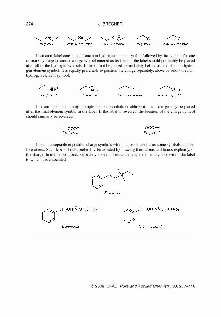
In an atom label consisting of one non-hydrogen element symbol followed by the symbols for oneor more hydrogen atoms, a charge symbol entered as text within the label should preferably be placedafter all of the hydrogen symbols. It should not be placed immediately before or after the non-hydro-gen element symbol. It is equally preferable to position the charge separately, above or below the non-hydrogen element symbol.
In atom labels containing multiple element symbols or abbreviations, a charge may be placedafter the final element symbol in the label. If the label is reversed, the location of the charge symbolshould similarly be reversed.
It is not acceptable to position charge symbols within an atom label, after some symbols, and be-fore others. Such labels should preferably be avoided by drawing their atoms and bonds explicitly, orthe charge should be positioned separately above or below the single element symbol within the labelto which it is associated.
J. BRECHER
© 2008 IUPAC, Pure and Applied Chemistry 80, 277–410
374
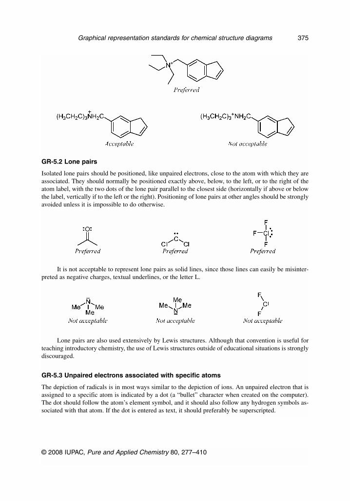
GR-5.2 Lone pairs
Isolated lone pairs should be positioned, like unpaired electrons, close to the atom with which they areassociated. They should normally be positioned exactly above, below, to the left, or to the right of theatom label, with the two dots of the lone pair parallel to the closest side (horizontally if above or belowthe label, vertically if to the left or the right). Positioning of lone pairs at other angles should be stronglyavoided unless it is impossible to do otherwise.
It is not acceptable to represent lone pairs as solid lines, since those lines can easily be misinter-preted as negative charges, textual underlines, or the letter L.
Lone pairs are also used extensively by Lewis structures. Although that convention is useful forteaching introductory chemistry, the use of Lewis structures outside of educational situations is stronglydiscouraged.
GR-5.3 Unpaired electrons associated with specific atoms
The depiction of radicals is in most ways similar to the depiction of ions. An unpaired electron that isassigned to a specific atom is indicated by a dot (a “bullet” character when created on the computer).The dot should follow the atom’s element symbol, and it should also follow any hydrogen symbols as-sociated with that atom. If the dot is entered as text, it should preferably be superscripted.
© 2008 IUPAC, Pure and Applied Chemistry 80, 277–410
Graphical representation standards for chemical structure diagrams 375

It is acceptable to omit the atom label for carbon atoms with associated unpaired electrons, butpreferable to include the atom label for clarity.
If an atom has more than one unpaired electron, a number indicating the count of unpaired elec-trons should be included directly before the dot, with both placed toward the top right of the associatedatom.
It is equally preferable to emphasize multiple radical character by placing the appropriate num-ber of unpaired electron dots adjacent to the element symbol. However, two dots should be placed nextto each other only when intended to represent a lone pair (GR-5.2). When representing two unpairedelectrons, the dots must remain well separated, or a numeric multiplier must be used instead, as above.
GR-5.4 Delocalized charges and unpaired electrons
As discussed in GR-6, charges and unpaired electrons that are delocalized across several atoms shouldbe depicted as separate graphical objects centered within the delocalized system. It is equally preferredto depict a “corner” at the top right of the diagram, with the symbol aligned with the top of the “cor-ner” and to its immediate right.
J. BRECHER
© 2008 IUPAC, Pure and Applied Chemistry 80, 277–410
376

GR-5.5 Radical ions
Radical ions should be depicted in similar ways, with the charge symbol immediately following the dot.
Monocharged polyradicals should be depicted with the unpaired electron dot and its associatedmultiplier enclosed in parentheses to avoid ambiguity about whether the multiplier applies to the chargeas well.
GR-5.6 Partial charges
In contrast to formal charges, partial charge indicators typically represent unspecified (and usuallynon-integral) charge values. They are most commonly used as qualitative indicators of electronegativ-ity or electropositivity. In general usage, partial charge indicators should be omitted from chemicalstructure diagrams; they should be used only when the author wishes to emphasize the partial chargedistribution.
Partial charge indicators may be shown to emphasize the polar nature of certain covalent bonds,to show the charge distribution in a molecule, or to show the atoms participating in hydrogen bonds.The partial charges are designated by symbols δ– and δ+ placed near the atom in question (see GR-11).In diagrams of neutral molecules that show partial charges, at least one each of the δ– and δ+ symbolsmust be shown. The δ– and δ+ symbols represent unspecified “small quantities” and need not be bal-anced numerically even in neutral molecules.
© 2008 IUPAC, Pure and Applied Chemistry 80, 277–410
Graphical representation standards for chemical structure diagrams 377

The mixing of formal and partial charges in one structure should be avoided. In particular, it isnot acceptable to use partial charge indicators to indicate the distribution of a real net charge via reso-nance.
Partial charge indicators may also be associated with delocalized systems, just as formal chargeindicators may be used.
Partial charges with specified non-integral values should be depicted analogously to the depictionof integral charges (see GR-5.1).
GR-5.7 Polyatomic ions
Polyatomic ions add an additional complication. Not only do they often include coordination bonds, butany net charge is usually best represented as delocalized over the entire ion (or a large part of it).
When exact atom-and-bond connectivity is not important, an ion may be best represented by itsmolecular formula. In accordance with the published recommendations for the nomenclature of in-organic chemistry, the formula should be placed in square brackets, and any charge should be reportedas a superscript following the rightmost bracket. For more information about the formatting of formu-las, see ref. [13].
If it is important to depict atoms and bonds explicitly, the ion should be drawn in full without con-cern for the delocalized charges. That structure should then be enclosed in large square brackets, andagain any charge should be reported as a superscript following the rightmost bracket. For single frag-ments, it is equally preferred to forgo the leftmost bracket and depict simply a “corner” at the top rightof the diagram, again with the charge as a superscript following the corner. The full paired bracketsshould be used in any situation where there is a possibility that the charge may be incorrectly associ-ated with an additional structure diagram to the left of the intended one.
J. BRECHER
© 2008 IUPAC, Pure and Applied Chemistry 80, 277–410
378
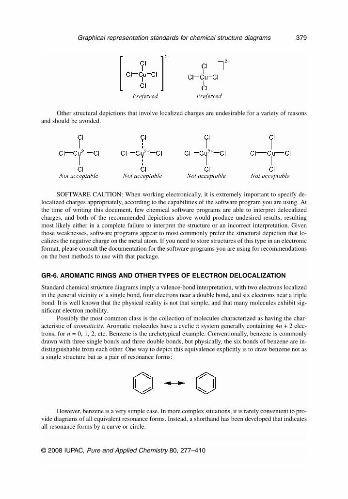
Other structural depictions that involve localized charges are undesirable for a variety of reasonsand should be avoided.
SOFTWARE CAUTION: When working electronically, it is extremely important to specify de-localized charges appropriately, according to the capabilities of the software program you are using. Atthe time of writing this document, few chemical software programs are able to interpret delocalizedcharges, and both of the recommended depictions above would produce undesired results, resultingmost likely either in a complete failure to interpret the structure or an incorrect interpretation. Giventhose weaknesses, software programs appear to most commonly prefer the structural depiction that lo-calizes the negative charge on the metal atom. If you need to store structures of this type in an electronicformat, please consult the documentation for the software programs you are using for recommendationson the best methods to use with that package.
GR-6. AROMATIC RINGS AND OTHER TYPES OF ELECTRON DELOCALIZATION
Standard chemical structure diagrams imply a valence-bond interpretation, with two electrons localizedin the general vicinity of a single bond, four electrons near a double bond, and six electrons near a triplebond. It is well known that the physical reality is not that simple, and that many molecules exhibit sig-nificant electron mobility.
Possibly the most common class is the collection of molecules characterized as having the char-acteristic of aromaticity. Aromatic molecules have a cyclic π system generally containing 4n + 2 elec-trons, for n = 0, 1, 2, etc. Benzene is the archetypical example. Conventionally, benzene is commonlydrawn with three single bonds and three double bonds, but physically, the six bonds of benzene are in-distinguishable from each other. One way to depict this equivalence explicitly is to draw benzene not asa single structure but as a pair of resonance forms:
However, benzene is a very simple case. In more complex situations, it is rarely convenient to pro-vide diagrams of all equivalent resonance forms. Instead, a shorthand has been developed that indicatesall resonance forms by a curve or circle:
© 2008 IUPAC, Pure and Applied Chemistry 80, 277–410
Graphical representation standards for chemical structure diagrams 379

These recommendations discuss preferred usages for these sorts of circles, and by extension, sim-ilar curves that represent other types of electron delocalization
GR-6.1 Curves should be drawn uniformly
Curves should be drawn to approach all associated bonds at a consistent distance. That means, basically,that a circle should be well centered within its framework of bonds. At its closest approach, the circleshould remain separated from each bond by a distance at least equivalent to the width of the bond, andno greater than twice the distance by which a double bond would be specified.
Additionally, there is no restriction that curves be circular. It is extremely common for curves tobe drawn as ellipses when they are associated with ring systems that are viewed in perspective. Curvesdo not have to be convex either (although non-convex delocalized systems are uncommon). Curvesdon’t even have to be closed: delocalization can also occur in non-cyclic systems such as the allyl rad-ical.
GR-6.2 Curves should be solid
Curves should be drawn as solid lines with the same width as a single bond.
GR-6.3 Curves represent delocalization
Above all else, curves represent delocalization. Accordingly, they may be used to depict systems thathave delocalized electrons.
J. BRECHER
© 2008 IUPAC, Pure and Applied Chemistry 80, 277–410
380
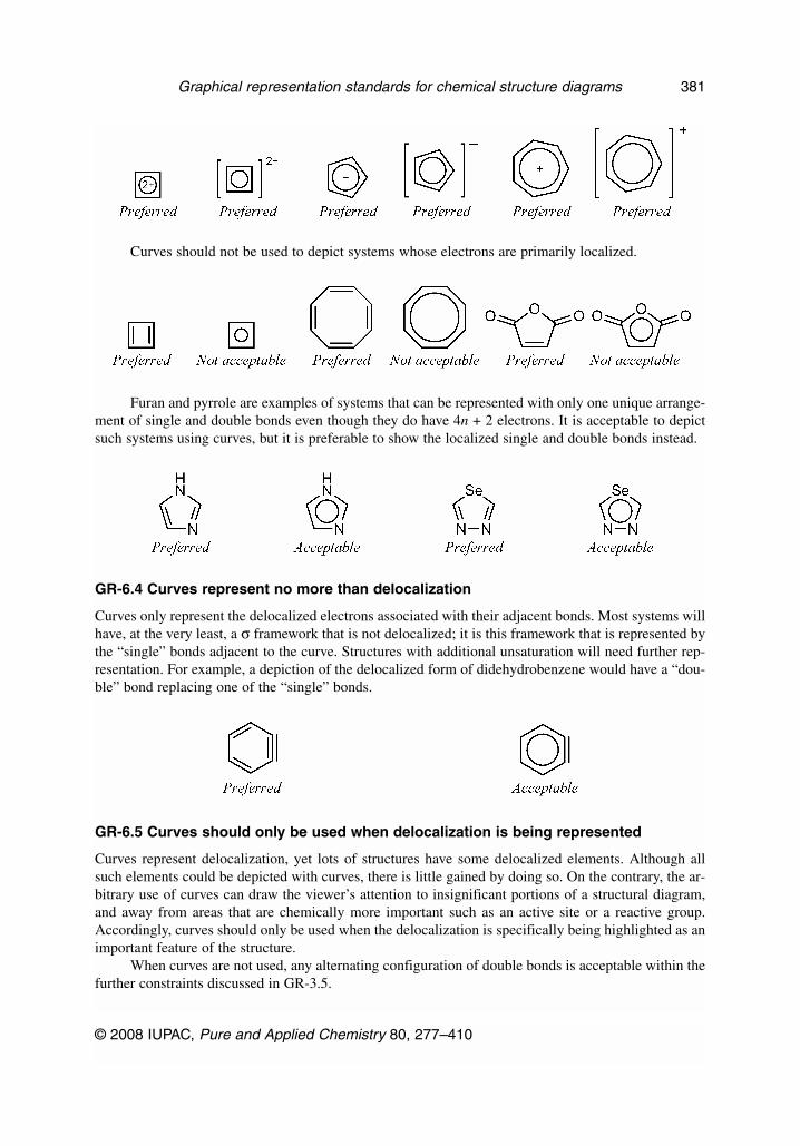
Curves should not be used to depict systems whose electrons are primarily localized.
Furan and pyrrole are examples of systems that can be represented with only one unique arrange-ment of single and double bonds even though they do have 4n + 2 electrons. It is acceptable to depictsuch systems using curves, but it is preferable to show the localized single and double bonds instead.
GR-6.4 Curves represent no more than delocalization
Curves only represent the delocalized electrons associated with their adjacent bonds. Most systems willhave, at the very least, a σ framework that is not delocalized; it is this framework that is represented bythe “single” bonds adjacent to the curve. Structures with additional unsaturation will need further rep-resentation. For example, a depiction of the delocalized form of didehydrobenzene would have a “dou-ble” bond replacing one of the “single” bonds.
GR-6.5 Curves should only be used when delocalization is being represented
Curves represent delocalization, yet lots of structures have some delocalized elements. Although allsuch elements could be depicted with curves, there is little gained by doing so. On the contrary, the ar-bitrary use of curves can draw the viewer’s attention to insignificant portions of a structural diagram,and away from areas that are chemically more important such as an active site or a reactive group.Accordingly, curves should only be used when the delocalization is specifically being highlighted as animportant feature of the structure.
When curves are not used, any alternating configuration of double bonds is acceptable within thefurther constraints discussed in GR-3.5.
© 2008 IUPAC, Pure and Applied Chemistry 80, 277–410
Graphical representation standards for chemical structure diagrams 381

By the same token, the use of curves is preferred for any system that cannot be adequately repre-sented by alternating single and double bonds.
It is generally not acceptable to use curves in two adjacent fused rings, since such diagrams areat best ambiguous in terms of the character of the shared fusion bond between the two rings. If it isknown that there is delocalization over only one ring in a fused ring system, a curve should be used forthat ring only.
GR-7. SALTS AND RELATED FORMS
Salts are characterized by having more than one component, most commonly with one or more cationiccomponents accompanied by one or more anionic component. Although such components are physi-cally associated by ionic bonds, they are traditionally depicted on paper as separate, disjoint fragments.So, in addition to all the issues involved with drawing each individual fragment, salts should also bedrawn with a consideration of how those fragments should be positioned in relation to each other.
It should be noted that although salts consist of cationic and anionic components, they are not al-ways drawn with explicit charges. Many pharmaceuticals, for example, are isolated as hydrochloridesalts. It is often reasonable—and, when the site of protonation is variable or uncertain, unavoidable—to draw such molecules with a neutral parent structure and a neutral hydrogen chloride.
Some molecules may be formally drawn with positive and negative charges within a single struc-tural fragment. The discussion here is limited to compounds that are or could be depicted using multi-ple fragments.
GR-7.1 Depiction of ionic bonds
Structures that are known to be ionic should be depicted as such. They should be drawn with atomsbearing explicit positive and negative charges, and there should be a space (rather than a bond) betweenthose atoms.
J. BRECHER
© 2008 IUPAC, Pure and Applied Chemistry 80, 277–410
382
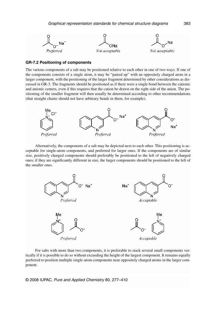
GR-7.2 Positioning of components
The various components of a salt may be positioned relative to each other in one of two ways. If one ofthe components consists of a single atom, it may be “paired up” with an oppositely charged atom in alarger component, with the positioning of the larger fragment determined by other considerations as dis-cussed in GR-3. The fragments should be positioned as if there were a single bond between the cationicand anionic centers, even if this requires that the cation be drawn on the right side of the anion. The po-sitioning of the smaller fragment will then usually be determined according to other recommendations(that straight chains should not have arbitrary bends in them, for example).
Alternatively, the components of a salt may be depicted next to each other. This positioning is ac-ceptable for single-atom components, and preferred for larger ones. If the components are of similarsize, positively charged components should preferably be positioned to the left of negatively chargedones; if they are significantly different in size, the larger components should be positioned to the left ofthe smaller ones.
For salts with more than two components, it is preferable to stack several small components ver-tically if it is possible to do so without exceeding the height of the largest component. It remains equallypreferred to position multiple single-atom components near oppositely charged atoms in the larger com-ponent.
© 2008 IUPAC, Pure and Applied Chemistry 80, 277–410
Graphical representation standards for chemical structure diagrams 383

When a salt contains many identical fragments, it is preferable to depict only one of them, withthat component preceded by a number that indicates its full stoichiometry. It remains acceptable to de-pict all of the identical components, of course.
SOFTWARE CAUTION: At the time of writing this document, there are few computer softwareprograms that are able to recognize stoichiometric multipliers. If chemical structure diagrams of multi-component salts are required for use within an electronic environment, it may be necessary to depict allof the components explicitly.
GR-7.3 Salts drawn in unspecified form
In addition to the styles discussed above, an alternative style depicts the ions in structural form, butwithout any implied association between the ions. This is the preferred form for mixed salts wherethere is more than one positively charged atom or more than one negatively charged atom, and wherethe author wishes to treat them separately. In this style, the largest ion(s) should be enclosed in brack-
J. BRECHER
© 2008 IUPAC, Pure and Applied Chemistry 80, 277–410
384

ets, to emphasize that there is no structural association between it (them) and the other ion(s). The se-lection of ions to bracket is performed solely based on size, and so the bracketed ion(s) may be posi-tively or negatively charged. The bracketed ions are placed on the left, and the other ions are placedon the right.
The various ions should be clearly separated from each other, but not separated so widely as toseem wholly unrelated. A separation distance roughly equivalent to the structure’s average bond lengthis usually reasonable for most purposes.
When an ion appears more than once, it may be depicted a single time, with an additional numeralpresent to indicate the repeat count.
If the repeated ion is represented by a molecular formula, the repeat count is placed to the left ofthe formula in regular-style (non-superscripted, non-subscripted text) and separated from the formulaby a space.
If the repeated ion is represented in structural form, it should be enclosed in brackets, and the re-peat count should be positioned as a subscript toward the bottom-right of the rightmost bracket of theion.
© 2008 IUPAC, Pure and Applied Chemistry 80, 277–410
Graphical representation standards for chemical structure diagrams 385

“Partial” or “acidic” salts would be best drawn in a manner similar to other types of salts.
Salts drawn as multiple neutral components (such as hydrochlorides) should not have the largerstructure enclosed in brackets. The larger structures are drawn to the left, and the smaller ones to theright, with a reasonable separation as discussed above. It is acceptable (but not required) to precedesmall neutral components by a center-dot if those components are represented as formulas. The center-dot, if present, should be separated from the formula by a space. If a repeat count is required as well asa center-dot, the center-dot should not be separated from the repeat count, but the repeat count shouldstill be separated from the rest of the formula by a space.
J. BRECHER
© 2008 IUPAC, Pure and Applied Chemistry 80, 277–410
386

GR-8. DOUBLE BONDS, DATIVE BONDS, AND CHARGE-SEPARATED FORMS
“The nitro problem” is one of the most familiar issues in chemical informatics: How should a nitrogroup be best represented? Experimentally, the two oxygen atoms are equivalent, so it would makesense to depict them symmetrically. However, any way to depict them symmetrically will either violatethe popular “octet rule” or force a double positive charge on the nitrogen atom. Conversely, any attemptto honor the octet rule results in oxygen atoms that appear to be non-equivalent.
Similar problems arise for molecules based on sulfur, phosphorus, and related elements.Furthermore, all of these are fairly common functional groups, and cannot readily be pushed aside as“unusual” cases.
GR-8.1 Nitrogen compounds
In the case of nitrogen compounds, a charge-separated depiction is recommended. While this does notpreserve the visual appearance of equivalent oxygen atoms, we feel that it is acceptable by analogy witharomatic structures. Benzene is commonly drawn with three single bonds and three double bonds, butit is understood that all six bonds are actually equivalent due to resonance delocalization between thetwo localized forms. Similarly, nitro groups should be considered to have both oxygen atoms equiva-lent through a similar resonance pair.
It is equally preferable, in the case of nitro groups, to avoid entirely the issue of depiction and in-stead display the functional group using the NO2 abbreviation as discussed in Table III. As discussedin GR-6, it is acceptable to represent delocalization with a curve when emphasis is needed for that de-localization. Other depiction styles are not acceptable, whether using two double bonds, a dative bond,or further separated charges.
© 2008 IUPAC, Pure and Applied Chemistry 80, 277–410
Graphical representation standards for chemical structure diagrams 387

Azides and the structurally similar diazo compounds should preferably be depicted as having twodouble bonds with a formal negative charge on the terminal atom and a formal positive charge on theatom adjacent to it. It is also acceptable to depict such compounds with a single bond and a triple bond,especially when discussing results that show experimental differences in those bond lengths.
SOFTWARE CAUTION: Although both depiction styles may be used for depicting azides anddiazo compounds, different software programs may interpret the two styles as referring to chemically
J. BRECHER
© 2008 IUPAC, Pure and Applied Chemistry 80, 277–410
388

different compounds. It may be necessary to use only the Preferred style when working in electronicenvironments.
GR-8.2 Phosphates and related Group V compounds
Functional groups containing phosphorus, arsenic, antimony, and bismuth are preferably depicted withnormal single and double bonds and without the addition of extra formal charges, even though such rep-resentations will violate the octet rule.
This depiction style should be preserved even for anions. The four oxygen atoms are chemicallyequivalent, but that equivalence is commonly understood through resonance.
GR-8.3 Sulfoxides, sulfones, sulfimides, and related Group VI compounds
Functional groups containing sulfur, selenium, and tellurium are also preferably depicted with normalsingle and double bonds and without the addition of extra formal charges, even though such represen-tations will violate the octet rule.
Again as with phosphorus, this depiction style should be preserved even for anions. The fouroxygen atoms are chemically equivalent, but that equivalence is commonly understood through reso-nance.
Similarly, there are some uncommon heterocycles that may be depicted either as zwitterions orwith two double bonds to the chalcogen atom. The form with two double bonds is preferred.
© 2008 IUPAC, Pure and Applied Chemistry 80, 277–410
Graphical representation standards for chemical structure diagrams 389
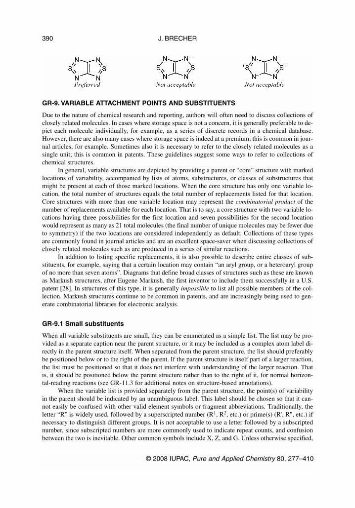
GR-9. VARIABLE ATTACHMENT POINTS AND SUBSTITUENTS
Due to the nature of chemical research and reporting, authors will often need to discuss collections ofclosely related molecules. In cases where storage space is not a concern, it is generally preferable to de-pict each molecule individually, for example, as a series of discrete records in a chemical database.However, there are also many cases where storage space is indeed at a premium; this is common in jour-nal articles, for example. Sometimes also it is necessary to refer to the closely related molecules as asingle unit; this is common in patents. These guidelines suggest some ways to refer to collections ofchemical structures.
In general, variable structures are depicted by providing a parent or “core” structure with markedlocations of variability, accompanied by lists of atoms, substructures, or classes of substructures thatmight be present at each of those marked locations. When the core structure has only one variable lo-cation, the total number of structures equals the total number of replacements listed for that location.Core structures with more than one variable location may represent the combinatorial product of thenumber of replacements available for each location. That is to say, a core structure with two variable lo-cations having three possibilities for the first location and seven possibilities for the second locationwould represent as many as 21 total molecules (the final number of unique molecules may be fewer dueto symmetry) if the two locations are considered independently as default. Collections of these typesare commonly found in journal articles and are an excellent space-saver when discussing collections ofclosely related molecules such as are produced in a series of similar reactions.
In addition to listing specific replacements, it is also possible to describe entire classes of sub-stituents, for example, saying that a certain location may contain “an aryl group, or a heteroaryl groupof no more than seven atoms”. Diagrams that define broad classes of structures such as these are knownas Markush structures, after Eugene Markush, the first inventor to include them successfully in a U.S.patent [28]. In structures of this type, it is generally impossible to list all possible members of the col-lection. Markush structures continue to be common in patents, and are increasingly being used to gen-erate combinatorial libraries for electronic analysis.
GR-9.1 Small substituents
When all variable substituents are small, they can be enumerated as a simple list. The list may be pro-vided as a separate caption near the parent structure, or it may be included as a complex atom label di-rectly in the parent structure itself. When separated from the parent structure, the list should preferablybe positioned below or to the right of the parent. If the parent structure is itself part of a larger reaction,the list must be positioned so that it does not interfere with understanding of the larger reaction. Thatis, it should be positioned below the parent structure rather than to the right of it, for normal horizon-tal-reading reactions (see GR-11.3 for additional notes on structure-based annotations).
When the variable list is provided separately from the parent structure, the point(s) of variabilityin the parent should be indicated by an unambiguous label. This label should be chosen so that it can-not easily be confused with other valid element symbols or fragment abbreviations. Traditionally, theletter “R” is widely used, followed by a superscripted number (R1, R2, etc.) or prime(s) (R', R", etc.) ifnecessary to distinguish different groups. It is not acceptable to use a letter followed by a subscriptednumber, since subscripted numbers are more commonly used to indicate repeat counts, and confusionbetween the two is inevitable. Other common symbols include X, Z, and G. Unless otherwise specified,
J. BRECHER
© 2008 IUPAC, Pure and Applied Chemistry 80, 277–410
390

multiple sites within a single diagram are considered to be independent (that is, the representation in-cludes all combinatorial products).
A label may also be used without an explicit list of allowed substituents. Such labels may be usedto indicate that substitution is permissible or likely, without specifying anything about the substituentsthemselves. If more than one substituent is indicated on the structure and those substituents may be dif-ferent, unique labels (R1, R2, etc.) should be used to emphasize the possibility of that difference.
Most commonly, variable substituents are connected to the parent structure by only one bond.Variable substituents connected to more than one bond should only be used when all fragments withinthe variable list are monoatomic or otherwise symmetric in terms of substitution.
In the absence of an external connection point drawn explicitly on the members of the variablelist, each item in that list is assumed to connect to the parent structure according to the standard rulesof valence, or by the first atom in the item if more than one atom has free valences.
Variable lists that also imply changes to bonding patterns are extremely confusing to the readerand are therefore not acceptable.
When the variable list is provided directly within the parent structure as an atom label, each listshould be enclosed in brackets to make it clear that the terms are associated. This should only be con-sidered for small lists that can be provided without impinging on other portions of the parent structure.
© 2008 IUPAC, Pure and Applied Chemistry 80, 277–410
Graphical representation standards for chemical structure diagrams 391

Unadorned lists are simplest to understand and should always be preferred to textual descriptionsof the variable substituents.
Large collections of small substituents may often be most conveniently presented in tabular form,especially when the substituents are not independent.
J. BRECHER
© 2008 IUPAC, Pure and Applied Chemistry 80, 277–410
392
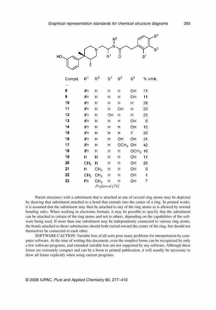
Parent structures with a substituent that is attached at one of several ring atoms may be depictedby drawing that substituent attached to a bond that extends into the center of a ring. In printed works,it is assumed that the substituent may then be attached to any of the ring atoms as is allowed by normalbonding rules. When working in electronic formats, it may be possible to specify that the substituentcan be attached to certain of the ring atoms and not to others, depending on the capabilities of the soft-ware being used. If more than one substituent may be independently connected to various ring atoms,the bonds attached to those substituents should both extend toward the center of the ring, but should notthemselves be connected to each other.
SOFTWARE CAUTION: Variable lists of all sorts pose many problems for interpretation by com-puter software. At the time of writing this document, even the simplest forms can be recognized by onlya few software programs, and extended variable lists are not supported by any software. Although theseforms are extremely compact and can be a boon to printed publication, it will usually be necessary todraw all forms explicitly when using current programs.
© 2008 IUPAC, Pure and Applied Chemistry 80, 277–410
Graphical representation standards for chemical structure diagrams 393

GR-9.2 Predefined substituent classes
Sometimes a substituent can be defined only by describing the general class to which it belongs. Someclasses are common enough that specific labels have traditionally been used to define them. When usedwithout accompanying text to further describe the substituents, the labels in Table GR-9.1 should onlybe used to represent the specific substituent classes listed.
Table GR-9.1 Structural labels that refer to aspecific class of substituents.
Alk alkylAlkyl alkylAr arylAryl arylE electrophileEWG electron-withdrawing groupM metalNu nucleophileQ heteroatom (not hydrogen, not carbon)
Use of those labels in conjunction with accompanying descriptive text should be avoided.However, if descriptive text is used with one of these labels, it should be used only to further restrictone of the listed classes (“Ar = halogen-substituted aryl”) and should not be used to describe an entirelyunrelated set of substituents (“Ar = methyl, ethyl, or propyl”).
If more than one of these labels is required in a given structure, they may be differentiated by theuse of superscripted numbers or primes as described above.
The use of the “Ar” label should be strongly avoided in any context where it might possibly beinterpreted to represent an argon atom. Since argon forms few molecules, contexts of this sort are ex-ceedingly uncommon.
The “R” label has in some cases been used to indicate alkyl substituents, and in other cases to in-dicate non-hydrogen substituents. However, it is more frequently used in the fully generic sense to in-dicate “some unknown substituent” without further restriction. Similarly, “X” has been used to repre-sent halogen atoms or, sometimes, also halogen-like substituents such as tosyl. We recommend thatthese labels be used either in conjunction with descriptive text (“R = alkyl”) or in the fully genericsense.
GR-9.3 Variable chain length and ring size
It is often convenient to specify that a chain or ring must be present, but that its actual length or sizemay vary. This may be accomplished by specifying the ring or chain atom, generally CH2, within brack-ets, then by following the brackets by a subscripted range of values to indicate the minimum and max-imum number of those atoms that may be present. Only homogenous chains should be represented inthis way. If multiple element types or unsaturated bonds may be present, they should be represented out-side of the variable section or another type of notation should be used entirely.
J. BRECHER
© 2008 IUPAC, Pure and Applied Chemistry 80, 277–410
394

It is also acceptable to use curved lines to emphasize that the number of atoms within a ring isvariable or unknown.
SOFTWARE CAUTION: At the time of writing this document, there is no software that supportsthe use of curved bonds. Although this representation is acceptable for general depiction, it must beconsidered not acceptable in cases where the resulting diagram will be further modified in electronicformat.
GR-9.4 Variable attachment location
In addition to allowing the type of attachment to vary, it may also be convenient to indicate that the at-tachment’s location is variable as well. This type of notation should be restricted to substituents that areknown to be bonded to a specific ring, but at an unspecified or unknown atom of that ring. The sub-stituent will always replace a hydrogen atom on one of the ring atoms, and cannot be bound to any atomthat lacks an attached hydrogen atom. Unless explicitly specified otherwise, such diagrams imply thatthe substituent may be bonded to any ring atom that has an attached hydrogen atom. Similarly, if morethan one such substituent is present for a given ring, the bonding of each substituent is independent ofall of the others. In other words, all permutations of bonding are represented by the single diagram.
SOFTWARE CAUTION: When working electronically, it is extremely important to specify thevariable attachment correctly, according to the capabilities of the software program you are using. If thevariable attachment is specified incorrectly, the structure may be interpreted as two disjoint fragments,with the variable bond being interpreted as a normal bond to a carbon atom. In addition to losing theintended variability, this misinterpretation will also add an additional CH4 to the structures perceivedformula: CH3 for the “methyl group” at the center of the ring, and one more H for the location in thering that was not substituted as intended.
GR-9.5 Large substituents
Graphically large substituents and large collections of substituents are most conveniently described intabular form.
SOFTWARE CAUTION: At the time of writing this document, there is no software that is ableto interpret this sort of tabular data. Nonetheless, it remains as an acceptable way of depicting large sub-stituents and large collections of substituents in printed form, even if it may be necessary to draw all in-dividual molecules explicitly if they are to be further modified by computer software.
© 2008 IUPAC, Pure and Applied Chemistry 80, 277–410
Graphical representation standards for chemical structure diagrams 395

In cases where the external connection points must be indicated for the variable substituents, suchindication should be unambiguous. Some attachment types are shown:
Philosophically, an external connection point represents a “null” atom. That is, the associatedbond is connected only to one atom. When the full structure is enumerated, the site represented by theexternal connection point is filled by an atom in the parent structure.
When a structural fragment is drawn with explicit bonds, the location of its attachment pointshould be shown explicitly. The attachment point should not be implied simply by the absence of a hy-drogen atom on a drawn structure.
J. BRECHER
© 2008 IUPAC, Pure and Applied Chemistry 80, 277–410
396

The point of attachment should not be indicated in a subtle manner such as by varying the lengthof a bond.
GR-10. TAUTOMERS
Graphical representations of molecules that can undergo tautomeric rearrangements always representthe single tautomer as drawn. This is consistent with IUPAC recommendations on chemical nomencla-ture [13,20].
GR-11. ANNOTATIONS
Annotations are bits of text that are closely associated with the atoms and bonds of a structure but notchemically meaningful themselves. They may describe something about the structure, or they may sim-ply provide a convenient label. In either case, they should be close enough to the subject of interest thatthey are clearly associated, and far enough from other objects that the nature of the association is notconfused.
SOFTWARE CAUTION: Some software programs may have special ways to create annotationsso that they remain associated with their target objects, or so that they may be indicated as having a spe-cific meaning. If you are using annotations in an electronic environment, you may want to take advan-tage of the features that your chemical drawing software offers in this area.
© 2008 IUPAC, Pure and Applied Chemistry 80, 277–410
Graphical representation standards for chemical structure diagrams 397

GR-11.1 Atom-based annotation
Annotations that describe a specific atom should be positioned close to that atom. Some common atom-based annotations include atom numbering and stereochemistry indicators.
Atom-based annotation is generally positioned in the largest open space near the atom, since thereis less chance that the annotation will be interpreted as referring to another object if there are fewer ob-jects nearby. When annotating several atoms in a ring system, it is also common to place the annota-tions within the ring. Annotations describing the stereochemical configuration of an atom will gener-ally be placed opposite one of the atom’s wedged or hashed wedged bonds.
Annotations should be clearly separated from the atom in question, whether it has a label or rep-resents an unlabeled carbon atom. However, they should also be closer to the atom in question than toany other atom. Typically, atom-based annotations will be separated from the atom by a distance on theorder of half the height of a “C” or an “H” in the font used for atom labels, but that distance may varyaccording to the aesthetics of the chemist. As a practical matter, the indicator will rarely be separatedfrom its atom by as much as the full height of a “C” or an “H” in the font used for atom labels.
Annotations should also be visually different from regular atom labels. Typically, they will bedrawn smaller. They may also be drawn in a different font, style, or color. If numeric indicators aredrawn smaller than regular atom labels, then care should be taken when positioning them to the right orleft of an existing atom label, lest they be mistaken for element repeat counts or isotopic labels.
J. BRECHER
© 2008 IUPAC, Pure and Applied Chemistry 80, 277–410
398

GR-11.1.1 AsterisksAsterisks have traditionally been used in several contexts: not only to indicate the presence of a stere-ogenic center, but also to specify isotopic labeling or excited states. Accordingly, the use of an asteriskas an indicator for any one of those items (including as an indicator of stereogenic centers) is poten-tially misleading and should be avoided. Any use of the asterisk should be undertaken with extremecare, and should generally be accompanied by additional descriptive text that explains its meaning inthat specific context.
GR-11.2 Bond-based annotation
Many of the issues relating to atom-based annotation also apply to bond-based annotation. Graphicalstereodescriptors are a common example of bond-based annotation. Annotations associated with a bondare generally positioned near the midpoint of the bond.
GR-11.3 Structure-based annotation
Annotations describing an entire structure are probably the most common sort of annotations. Nearlyevery structure depicted in a journal article will be identified by a letter or number nearby.
Structure-based annotation should be clearly associated with a specific structure. It should be po-sitioned so that it is closer to the target structure than to any other structure, but it should also be posi-tioned far enough away from the structure that it is not likely to be interpreted as an annotation of a sin-gle atom or bond within the structure. Typically, that means that it will be separated from the closestpart of the structure by a distance at least equal to half of the bond length used in the structure, and nofurther than twice as far as the structure’s bond length.
These annotations should be visually different both from atom labels and from atom- and bond-based annotation (if present). Typically, structure-based annotation will be drawn in a font that is thesame size as or larger than the structure’s atom labels. The font, style, or color may also be different.
Structure-based annotations will usually be placed below the structure. They will sometimes ap-pear to the left or right instead, but that positioning should be avoided in reaction schemes where thereare other structures to the left or right.
GR-12. PSEUDOBONDS
A pseudobond can be defined as a graphical linkage between two atoms that are not directly bound toeach other chemically. Pseudobonds should be always drawn in a fashion that is clearly distinguishablefrom regular covalent bond. Pseudobonds are used to simplify representation of complex structuressuch as macromolecules or coordination compounds.
© 2008 IUPAC, Pure and Applied Chemistry 80, 277–410
Graphical representation standards for chemical structure diagrams 399

SOFTWARE CAUTION: At the time of writing this document, there are few computer softwareprograms that are able to recognize pseudobonds of any sort. If chemical structure diagrams of suchmolecules are required for use within an electronic environment, it may be necessary to eschewpseudobonds and instead depict all of the atoms and bonds explicitly.
GR-12.1 Biological macromolecules
The representation of biological macromolecules often is simplified so only some of the “backbone”atoms connected with pseudobonds are shown. This method is especially useful for representation ofsecondary structure. For instance, a polypeptide backbone is often represented as a set of Cα–Cαpseudobonds [32]. For nucleic acids, several variants were suggested, such as pseudobonds between Pand C4' atoms in RNA [33] or between phosphate 3' oxygen atoms in DNA [34].
GR-12.2 Coordination polyhedra
In representations of coordination geometries, a different kind of graphical convention is often used.Configurations with seven or more ligands are most commonly depicted as polyhedral solids, wherepseudobonds connect the donor atoms of ligands and the central atoms are not shown. It is not accept-able, however, to represent some coordination geometries (TBPY-5; PBPY-7) with the equatorial planeshown with pseudobonds, while the axial ligands are linked to the central atom with “real” bonds.
J. BRECHER
© 2008 IUPAC, Pure and Applied Chemistry 80, 277–410
400

GR-12.3 Connectors
A connector is a variant of pseudobond used for schematic representation of molecules such as poly-dentate ligands where only a few atoms or groups are explicitly labeled. The connectors are usuallydrawn as curved bonds between atoms (groups) of interest.
Tetrapyrrole-metal complexes are often schematically represented as “wheels” with four spokes(i.e., each connector is a 90° segment). Such representation is acceptable and sometimes even preferredto detailed depiction of tetrapyrrole ligand, since there is no confusion between real bond (linear) andpseudobond (curved).
© 2008 IUPAC, Pure and Applied Chemistry 80, 277–410
Graphical representation standards for chemical structure diagrams 401

GR-13. LINEAR DRAWING STYLE
When presented in the “linear” drawing style, acyclic chains are drawn exclusively with horizontal andvertical bonds. Accordingly, their use is limited to those structures that truly can be represented usingonly horizontal and vertical bonds. Extremely congested structures, for example, are not suitable to thisdrawing style.
J. BRECHER
© 2008 IUPAC, Pure and Applied Chemistry 80, 277–410
402

Additionally, atoms with more than four attached bonds cannot be represented in this style.Accordingly, this style should be used to represent only relatively simple structures. Some further pointsare discussed below, and unless otherwise indicated, all other issues relating to chains in general (seeGR-3.2, etc.) would apply to the linear drawing style as well.
The linear drawing style is used primarily in introductory educational environments where it isnecessary to keep the diagrams as simple as possible. It should be considered as not acceptable for gen-eral usage.
GR-13.1 Atoms should be labeled
Because there is no “bend” in the chain of bonds, all atoms, including carbon and hydrogen atoms,should always be labeled explicitly.
GR-13.2 Bonds should be sufficiently long
The standard bond length used when drawing the structure should be long enough that the bonds arenot obscured by the atom labels. This is much more of a problem in this drawing style than in the“chain” style because it is much easier for a horizontally oriented atom label to obscure a horizontalbond than a bond at an angle.
© 2008 IUPAC, Pure and Applied Chemistry 80, 277–410
Graphical representation standards for chemical structure diagrams 403

GR-13.3 Substituents should preferentially be upwards
A substituent on a non-terminal atom should preferentially be positioned above that atom, rather thanbelow.
GR-13.4 Structure drawing styles should be consistent
If the linear drawing style is used for part of a structure, it should be used for the entire structure.Similarly, a group of related structures should be consistent in the style that is used among them.
GR-13.5 Rings are always drawn as rings
There is no equivalent of the linear style for use with cyclic structures. Any ring system should be drawnas a ring system, even if the rest of the structure is drawn using the linear drawing style. However, anybonds connecting the ring to the linear portion of the structure should remain horizontal or vertical.
J. BRECHER
© 2008 IUPAC, Pure and Applied Chemistry 80, 277–410
404

TABLE I. SAMPLE DRAWING STYLES FOR PUBLICATIONS
The following diagrams demonstrate a selection of drawing styles that are used or have recently beenused in various printed publications. All of these diagrams may be considered “preferred”, despite thewide variation in text (GR-0.3), bond lengths (GR-1.1), bond widths (GR-1.2), bond patterns (GR-1.3),and spacing of multiple bonds (GR-1.6). In each case, the combination of individual styles produces adiagram that is wholly legible, and that is more important than the specific numeric value of any singleproperty.
© 2008 IUPAC, Pure and Applied Chemistry 80, 277–410
Graphical representation standards for chemical structure diagrams 405
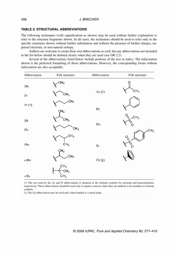
TABLE II. STRUCTURAL ABBREVIATIONS
The following nicknames (with capitalization as shown) may be used without further explanation torefer to the structure fragments shown. In all cases, the nicknames should be used to refer only to thespecific structures shown, without further substitution and without the presence of further charges, un-paired electrons, or non-natural isotopy.
Authors are welcome to create their own abbreviations as well, but any abbreviations not includedin the list below should be defined clearly when they are used (see GR-2.2).
Several of the abbreviations listed below include portions of the text in italics. The italicizationshown is the preferred formatting of those abbreviations. However, the corresponding forms withoutitalicization are also acceptable.
Abbreviation Full structure Abbreviation Full structure
(†) The text used by the Ac and Pr abbreviations is identical to the element symbols for actinium and praseodymium,respectively. Those abbreviations should be used only in organic contexts where they are unlikely to be mistaken as elementsymbols.(‡) The Cp abbreviation may be used only when bonded to a metal atom.
J. BRECHER
© 2008 IUPAC, Pure and Applied Chemistry 80, 277–410
406

TABLE III. COMMON CONTRACTED ATOM LABELS
Some very common contracted labels cannot be interpreted with a simple application of valence rules,but also need some implicit charges to be added. Others may represent slightly unusual bonding pat-terns. The labels shown below, along with their corresponding chalcogen analogs, may be freely usedwithin contracted labels; however, since they all have only a single point of attachment, the textualstrings shown below should always be the last (or only) text within a label or within a parenthesizedportion of a label. (The central rings and metal atoms in the examples below are provided simply asscaffolds to which these labels are attached. Both left-to-right and right-to-left forms of the label areshown.)
© 2008 IUPAC, Pure and Applied Chemistry 80, 277–410
Graphical representation standards for chemical structure diagrams 407

J. BRECHER
© 2008 IUPAC, Pure and Applied Chemistry 80, 277–410
408

REFERENCES
1. See, for example: W. A. Warr (Ed.). Chemical Structures 2: The International Language ofChemistry, Springer-Verlag, Berlin (1993).
2. D. Weininger. J. Chem. Inf. Comput. Sci. 30, 237 (1990).3. H. Helson. Rev. Comput. Chem. 13, 313 (1999).4. P. C. Fricker, M. Gastreich, M. Rarey. J. Chem. Inf. Comput. Sci. 44, 1065 (2004).5. A. M. Clark, P. Labute, M. Santavy. J. Chem. Inf. Model. 46, 1107 (2006).6. IUPAC Chemical Nomenclature and Structure Representation Division. Pure Appl. Chem. 78,
1897 (2006).7. (a) IUPAC-IUB Joint Commission on Biochemical Nomenclature. Eur. J. Biochem. 186, 429
(1989); (b) IUPAC-IUB Joint Commission on Biochemical Nomenclature. Eur. J. Biochem. 213,2 (1993); (c) IUPAC-IUB Joint Commission on Biochemical Nomenclature. Pure Appl. Chem.61, 1783 (1989); (d) R. A. Hill, D. N. Kirk, H. L. J. Makin, G. M. Murphy (Eds.). Dictionary ofSteroids, p. xxx, Chapman & Hall, London (1991).
8. A. M. Coghill, L. R. Garson (Eds.). The ACS Style Guide: A Manual for Authors and Editors,American Chemical Society, Washington, DC (2006).
9. R. Pirsig. Zen and the Art of Motorcycle Maintenance, Bantam Books, New York (1974). 10. (a) IUPAC-IUB Joint Commission on Biochemical Nomenclature. Eur. J. Biochem. 79, 1 (1977);
(b) IUPAC-IUB Joint Commission on Biochemical Nomenclature. Biochem. J. 171, 1 (1978).11. M. Beers (Ed.). The Merck Manual of Medical Information, 2nd home ed., Merck Laboratories,
Whitehouse Station, NJ (2003).12. A. W. Hofmann. Proc. Roy. Inst. 4, 414 (1865).13. IUPAC. Nomenclature of Inorganic Chemistry, IUPAC Recommendations 2005 (the “Red
Book”), N. G. Connelly, T. Damhus, R. M. Hartshorn, A. T. Hutton (Eds.), The Royal Society ofChemistry, Cambridge (2005).
14. IUPAC. Compendium of Chemical Terminology, 2nd ed. (the “Gold Book”), compiled by A. D.McNaught and A. Wilkinson, Blackwell Science, Oxford (1997). XML on-line corrected version:<http://goldbook.iupac.org> (2006–) created by M. Nic, J. Jirat, B. Kosata; updates compiled byA. Jenkins.
15. (a) IUPAC-IUBMB Joint Commission on Biochemical Nomenclature. Adv. Carbohydr. Chem.Biochem. 52, 43 (1997); (b) IUPAC-IUBMB Joint Commission on Biochemical Nomenclature.Carbohydr. Res. 297, 1 (1997); (c) IUPAC-IUBMB Joint Commission on BiochemicalNomenclature. J. Carbohydr. Chem. 16, 1191 (1997); (d) IUPAC-IUBMB Joint Commission onBiochemical Nomenclature. Pure Appl. Chem. 68, 1919 (1996).
16. (a) IUPAC-IUB Joint Commission on Biochemical Nomenclature. Biochem. J. 219, 345 (1984);(b) IUPAC-IUB Joint Commission on Biochemical Nomenclature. Eur. J. Biochem. 138, 9(1984); (c) IUPAC-IUB Joint Commission on Biochemical Nomenclature. Eur. J. Biochem. 152,1 (1985); (d) IUPAC-IUB Joint Commission on Biochemical Nomenclature. Int. J. Pept. ProteinRes. 24, 84 (1984); (e) IUPAC-IUB Joint Commission on Biochemical Nomenclature. J. Biol.Chem. 260, 14 (1985); (f) IUPAC-IUB Joint Commission on Biochemical Nomenclature. PureAppl. Chem. 56, 5954 (1984); (g) J. H. Jones (Ed.). Amino Acids and Peptides, SpecialistPeriodical Report, The Royal Society of Chemistry, 16, 387 (1985); (h) C. Liébecq (Ed.).Biochemical Nomenclature and Related Documents, 2nd ed., p. 39, Portland Press, London(1992).
17. E. Fischer. Ber. Dtsch. Chem. Ges. 24, 1836 (1891).18. E. Fischer. Ber. Dtsch. Chem. Ges. 24, 2683 (1891).19. R. B. Grossman. The Art of Writing Reasonable Organic Reaction Mechanisms, 2nd ed., Springer,
New York (2003).
© 2008 IUPAC, Pure and Applied Chemistry 80, 277–410
Graphical representation standards for chemical structure diagrams 409
20. W. H. Powell, H. Favre (Eds.). Nomenclature of Organic Chemistry, IUPAC Recommendations,Royal Society of Chemistry, in preparation. [See also, Nomenclature of Organic Chemistry,Pergamon Press, Oxford (1979); A Guide to IUPAC Nomenclature of Organic Compounds,Recommendations 1993, R. Panico, W. H. Powell, J.-C. Richer (Eds.), Blackwell Scientific,Oxford, 1993; and corrections in Pure Appl. Chem. 71, 1327 (1999)].
21. IUPAC Organic Chemistry Division. Commission on Nomenclature of Organic Chemistry. PureAppl. Chem. 70, 143 (1998).
22. IUPAC Organic Chemistry Division. Commission on Nomenclature of Organic Chemistry. PureAppl. Chem. 71, 513 (1999).
23. IUPAC Organic Chemistry Division. Commission on Nomenclature of Organic Chemistry. PureAppl. Chem. 71, 587 (1999).
24. (a) IUPAC-IUB Joint Commission on Biochemical Nomenclature. Eur. J. Biochem. 178, 277(1988); (b) IUPAC-IUB Joint Commission on Biochemical Nomenclature. Pure Appl. Chem. 59,779 (1987); (c) C. Liébecq (Ed.). Biochemical Nomenclature and Related Documents, 2nd ed.,p. 278, Portland Press, London (1992).
25. (a) IUPAC Commission on the Nomenclature of Organic Chemistry (CNOC) and IUPAC-IUBCommission on Biochemical Nomenclature (CBN). Biochem. J. 127, 741 (1972); (b) IUPACCommission on the Nomenclature of Organic Chemistry (CNOC) and IUPAC-IUB Commissionon Biochemical Nomenclature (CBN). Biochem. J. 151, 5 (1975); (c) IUPAC Commission on theNomenclature of Organic Chemistry (CNOC) and IUPAC-IUB Commission on BiochemicalNomenclature (CBN). Biochemistry 10, 4827 (1971); (d) IUPAC Commission on theNomenclature of Organic Chemistry (CNOC) and IUPAC-IUB Commission on BiochemicalNomenclature (CBN). Biochemistry 14, 1803 (1975); (e) IUPAC Commission on theNomenclature of Organic Chemistry (CNOC) and IUPAC-IUB Commission on BiochemicalNomenclature (CBN). Eur. J. Biochem. 25, 397 (1972); (f) IUPAC Commission on theNomenclature of Organic Chemistry (CNOC) and IUPAC-IUB Commission on BiochemicalNomenclature (CBN). Eur. J. Biochem. 57, 317 (1975); (g) IUPAC Commission on theNomenclature of Organic Chemistry (CNOC) and IUPAC-IUB Commission on BiochemicalNomenclature (CBN). J. Biol. Chem. 247, 2633 (1972); (h) IUPAC Commission on theNomenclature of Organic Chemistry (CNOC) and IUPAC-IUB Commission on BiochemicalNomenclature (CBN). Pure Appl. Chem. 41, 405 (1975); (i) C. Liébecq (Ed.). BiochemicalNomenclature and Related Documents, 2nd ed., p. 226, Portland Press, London (1992).
26. IUPAC. Compendium of Macromolecular Nomenclature (the “Purple Book”), W. V. Metanomski(Ed.), Blackwell Scientific, Oxford (1991).
27. IUPAC Commission on Macromolecular Nomenclature. Pure Appl. Chem. 74, 915 (2002).28. E. A. Markush. U.S. Patent 1,506,316, Aug. 26, 1924.29. T. J. Oldfield, R. E. Hubbard. Proteins: Struct., Funct., Genet. 18, 324 (1994).30. C. M. Duarte, A. M. Pyle. J. Mol. Biol. 284, 1465 (1998).31. L. Stewart, M. R. Redinbo, X. Qiu, W. G. J. Hol, J. J. Champoux. Science 279, 1534 (1998).
J. BRECHER
© 2008 IUPAC, Pure and Applied Chemistry 80, 277–410
410