Embed Size (px)
Citation preview
Grant VORTEX Pro External CombiCombi 21e, Combi 26e and Combi 36e Condensing Oil Boiler Range
Installation & Servicing Instructions
Part No. DOC 89. Rev 00. May 2012
Commissioning Report
2
Co
mm
issi
oni
ngR
epo
rt
For use with Kerosene* only.After installing the boiler leave theseinstructions with the User.
This appliance is deemed a controlledservice and specific regional statutoryrequirements may be applicable.
*Operation on Bio-fuelAll Grant Vortex Pro condensing boilers,manufactured since May 2011, aresuitable for operation on both standardkerosene (Class C2 to BS2869) andalso bio-kerosene – up to a 30% blend(B30K).
All burner settings and nozzle sizes (asdetailed in Section 2.3 of this manual)are correct for both standard keroseneand bio-kerosene (B30K).
In order to operate this boiler on bio-kerosene it will be necessary to take the following actions:
a) Use a bio-kerosene (B30K)compatible flexible oil line in place of the oil line supplied with this boiler.
b) Have your oil storage tank and oilsupply line (including all pipework, sightgauges, filters, isolating valves, firevalves, de-aeration devices, etc.)checked for their compatibility with bio-kerosene (B30K).
Where necessary some, or all, of theseitems may have to be replaced with abio-kerosene compatible alternative.
c) Check the suitability of the fluesystem with Grant UK.
d) Use only bio-kerosene (B30K) thatconforms to OPS24.
IMPORTANTUnder no circumstances should theboiler be used with bio-kerosenewithout the above actions being takenfirst.
Date:
Commissioning engineer:
Tel. No:
Boiler model: Boiler output: kW
Fuel type: Kerosene
Nozzle size: Pump pressure:
Air setting: Flue gas % CO2:
Net flue gas temp: Smoke No:
System flushed: Yes / No
Corrosion inhibitor added: Yes / No
Antifreeze added: Yes / No
(where there is a Yes / No - please circle appropriate answer)
GRANT ENGINEERING (UK) LIMITEDHopton House, Hopton Industrial Estate, Devizes, Wiltshire SN10 2EUTel: 01380 736920 Fax: 01380 736991Email: [email protected] www.grantuk.com
This manual is accurate at the date of printing but will be superseded and should be disregarded if specifications and/orappearances are changed in the interests of continued product improvement.All good sold are subject to our official Conditions of Sale, a copy of which may be obtained on application.© Grant Engineering (UK) Limited 2012. No part of this manual may be reproduced by any means without prior written consent.
For sealed systems only:Expansion vessel size : litres
Expansion vessel change pressure : bar
Sealed system fill pressure (cold) : bar
Service LogIt is recommended that the boiler should be regularly serviced, at least once a year,and the details entered in the Boiler Handbook by the service engineer.
Contents
Co
nten
ts
3
1 Introduction 41.1 How a Condensing Boiler Works 4
1.2 Boiler Description 4
2 Technical Data 62.1 Boiler Technical Data 6
2.2 Approximate Air Damper Setting 7
2.3 Vortex Pro Combi e Oil Boilers using Class C2 Kerosene 7
2.4 Flue Gas Analysis 7
2.5 Boiler Dimensions 7
3 Oil Storage & Supply System 83.1 Fuel Supply 8
3.2 Burner Oil Connection 11
4 Boiler Installation Information 124.1 Introduction 12
4.2 Boiler Location 12
4.3 Preparation for Installation 12
4.4 Installing the Boiler 12
4.5 Expansion Vessel 13
4.6 Filling and Venting the System 13
4.7 Regulations Compliance Requirements 13
4.8 Completion 14
4.9 Before you Commission 14
4.10 Underfloor Heating Systems 14
4.11 Pipework Materials 14
4.12 Sealed Systems 14
4.13 Underfloor Pipework 14
5 Pipe Connections 155.1 Water Connections 15
5.2 Making the Water Connections 15
5.3 Domestic Hot Water System 16
5.4 To use the Water Hardness Kit 16
6 Condensate Disposal 176.1 General Requirements 17
6.2 Connections 17
6.3 Pipework 17
6.4 External Pipework 17
6.5 Condensate Soakaway 17
6.6 Condensate Trap 18
6.7 Condensate Disposal Pipework 18
6.8 Inspection and Cleaning of Trap 18
7 Sealed Systems 197.1 System Models 19
8 Electrical 208.1 Connecting the Power Supply 20
8.2 Connecting the Controls - Heating Only 22
8.3 Connecting the Controls - Heating and Hot Water 23
8.4 Connecting a Remote Frost Thermostat 25
9 Flue System & Air Supply 269.1 Low Level Discharge Flue 26
9.2 Grant Green System 27
9.3 Grant Hybrid System 27
9.4 Grant Horizontal System 28
9.5 General Guidance 28
9.6 Air Supply 28
10 Commissioning 3010.1 Before Switching On 30
10.2 Switching On 30
10.3 Running the Boiler 31
10.4 Balancing the System 31
10.5 Completion 31
10.6 Air Adjuster Disc - Combi 21 only 32
10.7 Information for the User 32
11 Boiler Servicing 3311.1 Checking before Servicing 33
11.2 Dismantling Prior to Servicing 33
11.3 Cleaning the Boiler 33
11.4 Cleaning the Burner 35
12 Fault Finding 3612.1 Initial Checklist - for Installer or
Service Engineers 36
12.2 Main Fault Finding Procedure 37
12.3 Poor Hot Water Checklist 40
12.4 Riello RDB Burner Fault Finding 41
13 Spare Parts 42
14 Health & Safety Information 4414.1 Insulation Materials 44
14.2 Insulation Materials 44
14.3 Kerosene and Gas Oil Fuels (mineral oils) 44
15 EC Declaration of Conformity 45
16 Warranty 4616.1 The Vortex Oil Boiler Warranty 46
16.2 Extended Warranty 47
1 Introduction
4
Intr
od
ucti
on
Warning of possible human injury asa consequence of not following theinstructions in the warning.
The Grant VORTEX Pro Combi econdensing boilers contain an extraheat exchanger which is designed torecover the latent heat normally lost bya conventional boiler. It does this bycooling the flue gases to below 90° C,thus extracting more sensible heat andsome of the latent heat. This is achievedby cooling the flue gases to their dewpoint (approximately 55° C).
To ensure maximum efficiency, the boilerreturn temperature should be 55° C orless, this will enable the latent heat to becondensed out of the flue gases.
The boiler will achieve net thermalefficiencies of 100%.
To achieve maximum performance fromthe Grant VORTEX Pro Combi e boilers,it is recommended that the heatingsystem is designed so that atemperature differential of 20°Cbetween the flow and return ismaintained.
The Grant Vortex Pro Combi e boilerswill however still operate at extremelyhigh efficiencies even when it is not incondensing mode and therefore issuitable for fitting to an existing heatingsystem without alteration to the radiatorsizes. The boiler is capable of amaximum flow temperature of 78° C.
1.2 Boiler DescriptionThe Vortex Pro Combi e boilers areautomatic pressure jet oil boilersdesigned for use with a sealed centralheating system and will providedomestic hot water at mains pressure.
All boilers are supplied with the controlpanel and the burner factory fitted, anda factory fitted low level discharge fuelsystem.
Caution concerning likely damage toequipment or tools as aconsequence of not following theinstructions in the caution.
Note text. Used for emphasis orinformation not directly concernedwith the surrounding text but ofimportance to the reader.
1.1 How a CondensingBoiler WorksDuring the combustion process,hydrogen and oxygen combine toproduce heat and water vapour. Thewater vapour produced is in the form of superheated steam in the heatexchanger. This superheated steamcontains sensible heat (available heat)and latent heat (heat locked up in theflue gas). A conventional boiler cannotrecover any of the latent heat and thisenergy is lost to the atmospherethrough the flue.
! WARNING
! CAUTION
! NOTE
For conventional flue applications,where required, Grant recommendsthe use of the Grant 'Green' fluesystem, to provide an insulated twin -wall flue system. Refer to Section 9for further details.
Only Kerosene must be used with alow level discharge flue appliance.The Vortex Pro Combi e boilers areonly suitable for use with Kerosene.
All burners are ready to connect to asingle pipe system with a loose flexiblefuel line (900mm) and 3/8” to 1/4” BSPmale adaptor supplied with the boiler. Ifrequired, an additional flexible fuel line(900mm) and 3/8” to 1/4” BSP maleadaptor are available to purchase fromGrant Engineering (UK) Limited, for two-pipe oil supply system, Part No. RBS36.
The temperature of the water leavingthe boiler to heat the radiators is Useradjustable.
The setting of the boiler thermostat onthe Vortex Pro Combi e boilers has noeffect on the hot water performance.
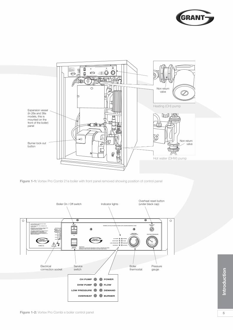
Figure 1-1 shows the components inthe Vortex Pro Combi e boilers and theposition of the control panel. Figure 1-2shows the details of the control panel.
! NOTEThis manual is intended to guideengineers in the installation andmaintenance of Grant VORTEX ProExternal Combi e boilers. A separatemanual is available to guide users inthe operation of these boilers, and isprinted inverted at the end of thismanual.
The following special text formats areused in this manual for the purposeslisted below:
Intr
od
ucti
on
5
IMPORTANTCABLE TO PLUG MUST BE SECURED IN CABLE CLAMP BELOW PANEL
MAXIMUM CABLE LENGTH BETWEEN PLUG AND CLAMP 350mm
WARNING 230V ISOLATE MAINS POWER SUPPLY BEFORE REMOVING COVER
1
2
N
3
N
L
Figure 1-1: Vortex Pro Combi 21e boiler with front panel removed showing position of control panel
IMPORTANTCABLE TO PLUG MUST BE SECURED IN CABLE CLAMP BELOW PANELMAXIMUM CABLE LENGTH BETWEEN PLUG AND CLAMP 350mm
WARNING 230V ISOLATE MAINS POWER SUPPLY BEFORE REMOVING COVER
1
2
N
3
N
L
Figure 1-2: Vortex Pro Combi e boiler control panel
Electricalconnection socket
Serviceswitch
Boilerthermostat
Pressuregauge
Boiler On / Off switch
Expansion vessel(In 26e and 36emodels, this ismounted on thefront of the boiler)panel
Burner lock-outbutton
Indicator lightsOverheat reset button(under black cap)
Hot water (DHW) pump
Non returnvalve
Heating (CH) pump
Non returnvalve
2 Technical Data
6
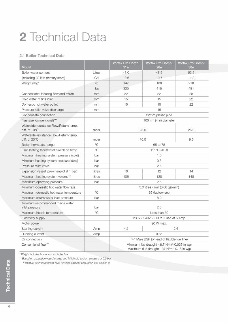
2.1 Boiler Technical Data
Vortex Pro Combi Vortex Pro Combi Vortex Pro CombiModel 21e 26e 36e
Boiler water content Litres 48.0 48.5 53.5
(including 32 litre primary store) Gal 10.6 10.7 11.8
Weight (dry)* kg 147 188 218
lbs 325 415 481
Connections: Heating flow and return mm 22 22 28
Cold water mains inlet mm 15 15 22
Domestic hot water outlet mm 15 15 22
Pressure relief valve discharge mm 15
Condensate connection 22mm plastic pipe
Flue size (conventional)*** 100mm (4 in) diameter
Waterside resistance Flow/Return temp. diff. of 10°C mbar 28.5 26.0
Waterside resistance Flow/Return temp. diff. of 20°C mbar 10.0 9.5
Boiler thermostat range °C 65 to 78
Limit (safety) thermostat switch off temp. °C 111°C +0 -3
Maximum heating system pressure (cold) bar 1.0
Minimum heating system pressure (cold) bar 0.5
Pressure relief valve bar 2.5
Expansion vessel (pre-charged at 1 bar) litres 10 12 14
Maximum heating system volume** litres 106 128 148
Maximum operating pressure bar 2.5
Minimum domestic hot water flow rate 3.0 litres / min (0.66 gal/min)
Maximum domestic hot water temperature °C 65 (factory set)
Maximum mains water inlet pressure bar 8.0
Minimum recommended mains water inlet pressure bar 2.5
Maximum hearth temperature °C Less than 50
Electricity supply 230V / 240V ~ 50Hz Fused at 5 Amp
Motor power 90 W max.
Starting current Amp 4.2 2.6
Running current Amp 0.85
Oil connection 1/4” Male BSP (on end of flexible fuel line)
Conventional flue*** Minimum flue draught - 8.7 N/m² (0.035 in wg)Maximum flue draught - 37 N/m² (0.15 in wg)
* Weight includes burner but excludes flue
** Based on expansion vessel charge and initial cold system pressure of 0.5 bar
*** If used as alternative to low level terminal supplied with boiler (see section 9)
Tech
nica
l Dat
a
2.2 Approximate Air DamperSetting
Burners are supplied factory set atthe outputs shown.
When commissioning, the air dampermust be adjusted to obtain thecorrect CO2 level and the Installermust amend the data label.
2.3 Vortex Pro Combi Oil Boilersusing Class C2 Kerosene
.
Vortex Combi e boilers are only foruse with kerosene.
! NOTE
! NOTE
The data given above is approximateonly and is based on the boiler beingused with a low level discharge flue.
The above settings may have to beadjusted on site for the correctoperation of the burner.
Gas Oil is not suitable for use with aGrant Vortex Pro Combi e boiler.
The net flue gas temperatures givenabove are ± 10%.
When commissioning the air dampermust be adjusted to obtain the correctCO2 level.
2.4 Flue Gas AnalysisTo allow the boiler to be commissionedand serviced, the boiler is supplied witha combustion test point on the frontcleaning door. When this test point isused please note the following:
• The test point is for CO2 and smokereadings only.
• The boiler efficiency andtemperature must be taken from theflue.
• Final combustion readings must betaken from the flue terminal (or testpoint on flue elbow if Green systemis used) with all panels fitted.
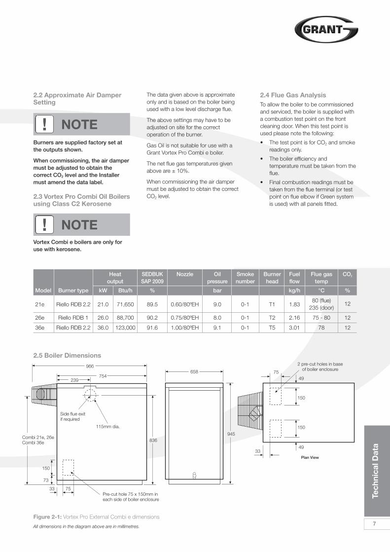
Figure 2-1: Vortex Pro External Combi e dimensions
All dimensions in the diagram above are in millimetres.
2.5 Boiler Dimensions
966
239
Combi 21e, 26eCombi 36e
Side flue exitif required
Pre-cut hole 75 x 150mm ineach side of boiler enclosure
2 pre-cut holes in baseof boiler enclosure
115mm dia.
754
836
150
73
7533
945
33
75
150
49
49
150
658
Heat SEDBUK Nozzle Oil Smoke Burner Fuel Flue gas CO2
output SAP 2009 pressure number head flow temp
Model Burner type kW Btu/h % bar kg/h °C %
21e Riello RDB 2.2 21.0 71,650 89.5 0.60/80ºEH 9.0 0-1 T1 1.8380 (flue) 12
235 (door)
26e Riello RDB 1 26.0 88,700 90.2 0.75/80ºEH 8.0 0-1 T2 2.16 75 - 80 12
36e Riello RDB 2.2 36.0 123,000 91.6 1.00/80ºEH 9.1 0-1 T5 3.01 78 12
Tech
nica
l Dat
a
7
Plan View
8
Oil
Sto
rag
e &
Sup
ply
Sys
tem
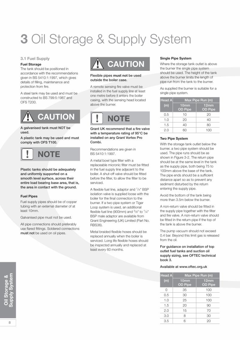
3 Oil Storage & Supply SystemSingle Pipe System
Where the storage tank outlet is abovethe burner the single pipe systemshould be used. The height of the tankabove the burner limits the length ofpipe run from the tank to the burner.
As supplied the burner is suitable for asingle pipe system.
Head A Max Pipe Run (m)
(m) 10mm 12mmOD Pipe OD Pipe
0.5 10 20
1.0 20 40
1.5 40 80
2.0 60 100
Head A Max Pipe Run (m)
(m) 10mm 12mmOD Pipe OD Pipe
0 35 100
0.5 30 100
1.0 25 100
1.5 20 90
2.0 15 70
3.0 8 30
3.5 6 20
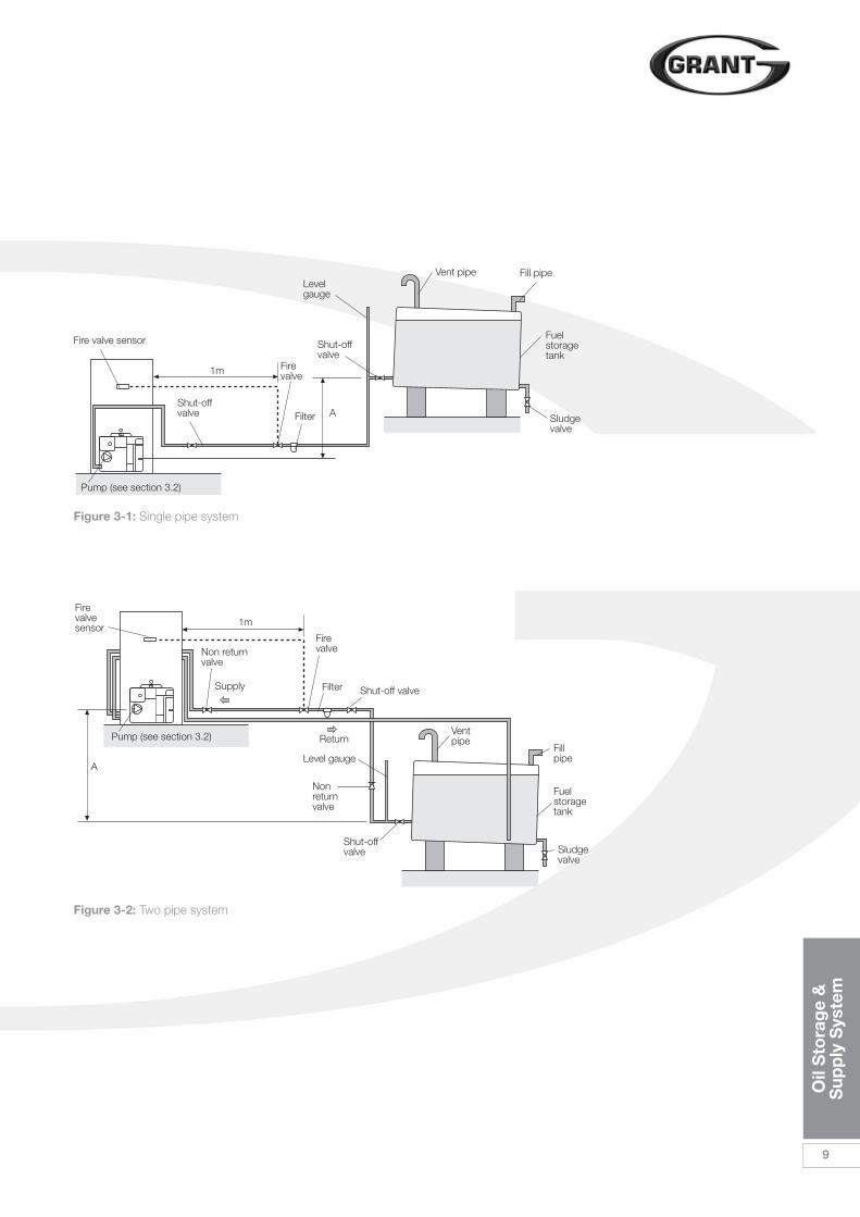
Two Pipe System
With the storage tank outlet below theburner, a two pipe system should beused. The pipe runs should be asshown in Figure 3-2. The return pipeshould be at the same level in the tankas the supply pipe, both being 75 to100mm above the base of the tank. The pipe ends should be a sufficientdistance apart so as to prevent anysediment disturbed by the returnentering the supply pipe.
Avoid the bottom of the tank beingmore than 3.5m below the burner.
A non-return valve should be fitted inthe supply pipe together with the filterand fire valve. A non-return valve shouldbe fitted in the return pipe if the top ofthe tank is above the burner.
The pump vacuum should not exceed0.4 bar. Beyond this limit gas is releasedfrom the oil.
For guidance on installation of topoutlet fuel tanks and suction oilsupply sizing, see OFTEC technicalbook 3.
Available at www.oftec.org.uk
3.1 Fuel SupplyFuel StorageThe tank should be positioned inaccordance with the recommendationsgiven in BS 5410:1:1997, which givesdetails of filling, maintenance andprotection from fire.
A steel tank may be used and must beconstructed to BS 799:5:1987 and OFS T200.
A galvanised tank must NOT beused.
A plastic tank may be used and mustcomply with OFS T100.
Plastic tanks should be adequatelyand uniformly supported on asmooth level surface, across theirentire load bearing base area, that is,the area in contact with the ground.
Fuel Pipes
Fuel supply pipes should be of coppertubing with an external diameter of atleast 10mm.
Galvanised pipe must not be used.
All pipe connections should preferablyuse flared fittings. Soldered connectionsmust not be used on oil pipes.
Flexible pipes must not be usedoutside the boiler case.
A remote sensing fire valve must beinstalled in the fuel supply line at leastone metre before it enters the boilercasing, with the sensing head locatedabove the burner.
Recommendations are given in BS 5410:1:1997.
A metal bowl type filter with areplaceable micronic filter must be fittedin the fuel supply line adjacent to theboiler. A shut-off valve should be fittedbefore the filter, to allow the filter to beserviced.
A flexible fuel line, adaptor and 1/4" BSPisolation valve is supplied loose with theboiler for the final connection to theburner. If a two pipe system or TigerLoop system is used, an additionalflexible fuel line (900mm) and 3/8" to 1/4"BSP male adaptor are available fromGrant Engineering (UK) Limited (Part No.RBS36).
Metal braided flexible hoses should bereplaced annually when the boiler isserviced. Long life flexible hoses shouldbe inspected annually and replaced atleast every 60 months.
! NOTE
! CAUTION
! CAUTIONGrant UK recommend that a fire valvewith a temperature rating of 95°C beinstalled on any Grant Vortex ProCombi.
! NOTE
Oil
Sto
rag
e &
Sup
ply
Sys
tem
9
Figure 3-1: Single pipe system
Figure 3-2: Two pipe system
Firevalve1m
1m
A
Fire valve sensor
Vent pipe Fill pipe
Sludgevalve
Shut-offvalve
Shut-offvalve
Levelgauge
Filter
Fuelstoragetank
Pump (see section 3.2)
Pump (see section 3.2)
Firevalve
Firevalvesensor
Ventpipe
Fillpipe
Sludgevalve
Non returnvalve
Shut-offvalve
Shut-off valve
Level gauge
Nonreturnvalve
Filter
Fuelstoragetank
A
Supply
Return
10
Oil
Sto
rag
e &
Sup
ply
Sys
tem
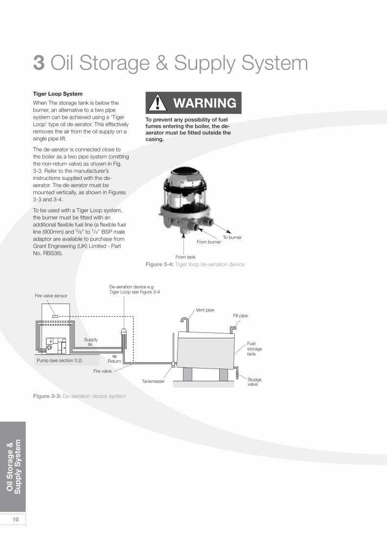
3 Oil Storage & Supply SystemTiger Loop System
When The storage tank is below theburner, an alternative to a two pipesystem can be achieved using a ‘TigerLoop’ type oil de-aerator. This effectivelyremoves the air from the oil supply on asingle pipe lift.
The de-aerator is connected close tothe boiler as a two pipe system (omittingthe non-return valve) as shown in Fig. 3-3. Refer to the manufacturer’sinstructions supplied with the de-aerator. The de-aerator must bemounted vertically, as shown in Figures3-3 and 3-4.
To be used with a Tiger Loop system,the burner must be fitted with anadditional flexible fuel line (a flexible fuelline (900mm) and 3/8” to 1/4” BSP maleadaptor are available to purchase fromGrant Engineering (UK) Limited - PartNo. RBS36).
To prevent any possibility of fuelfumes entering the boiler, the de-aerator must be fitted outside thecasing.
! WARNING
Figure 3-4: Tiger loop de-aeration device
To burnerFrom burner
From tank
Figure 3-3: De-aeration device system
Fire valve
Supply
Return
Fire valve sensor
Vent pipeFill pipe
Sludgevalve
Tankmaster
Fuelstoragetank
De-aeration device e.gTiger Loop see Figure 3-4
Pump (see section 3.2)
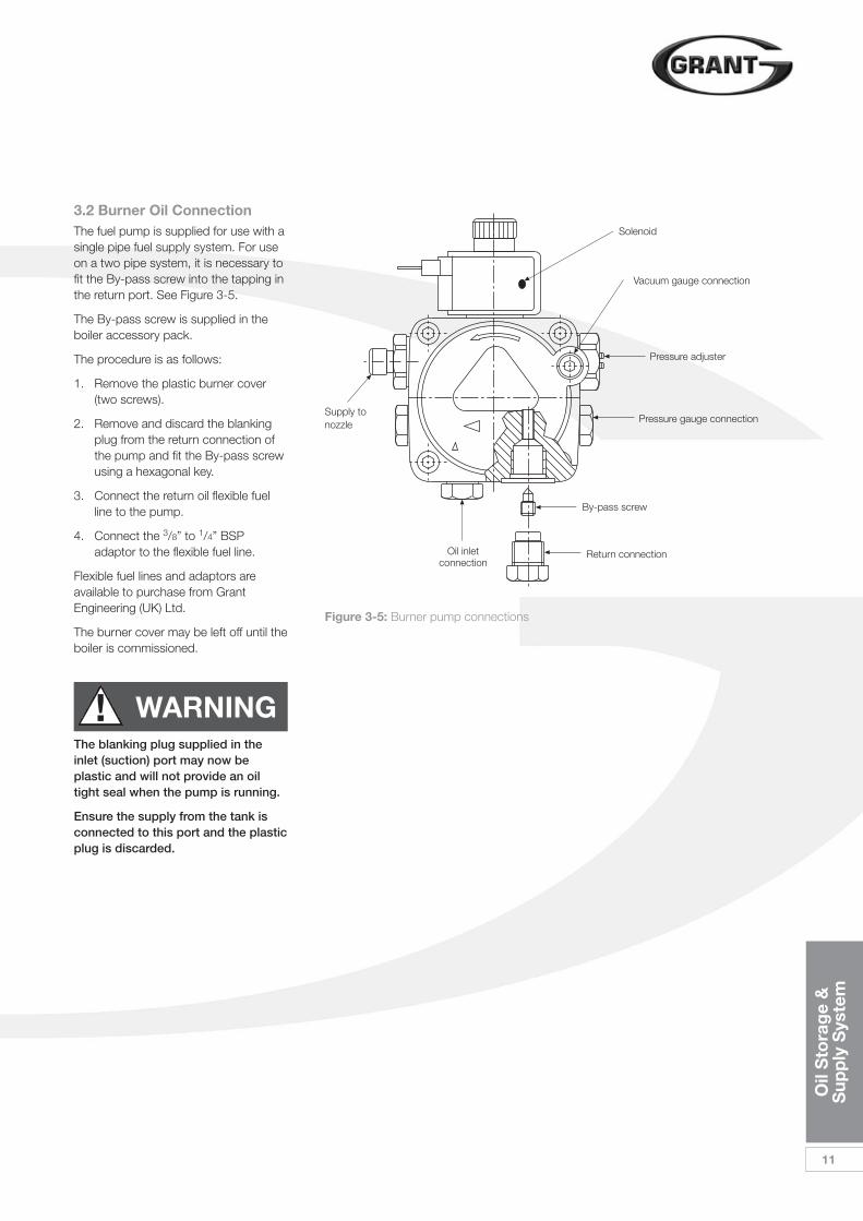
Figure 3-5: Burner pump connections
Oil inletconnection
Return connection
By-pass screw
Pressure gauge connection
Pressure adjuster
Vacuum gauge connection
Solenoid
Supply tonozzle
Oil
Sto
rag
e &
Sup
ply
Sys
tem
11
3.2 Burner Oil ConnectionThe fuel pump is supplied for use with asingle pipe fuel supply system. For useon a two pipe system, it is necessary tofit the By-pass screw into the tapping inthe return port. See Figure 3-5.
The By-pass screw is supplied in theboiler accessory pack.
The procedure is as follows:
1. Remove the plastic burner cover(two screws).
2. Remove and discard the blankingplug from the return connection ofthe pump and fit the By-pass screwusing a hexagonal key.
3. Connect the return oil flexible fuelline to the pump.
4. Connect the 3/8” to 1/4” BSPadaptor to the flexible fuel line.
Flexible fuel lines and adaptors areavailable to purchase from GrantEngineering (UK) Ltd.
The burner cover may be left off until theboiler is commissioned.
The blanking plug supplied in theinlet (suction) port may now beplastic and will not provide an oiltight seal when the pump is running.
Ensure the supply from the tank isconnected to this port and the plasticplug is discarded.
! WARNING
4 Boiler Installation Information
12
Bo
iler
Inst
alla
tio
nIn
form
atio
n
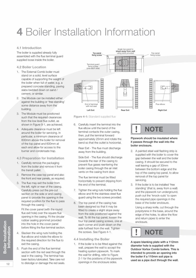
4.1 IntroductionThe boiler is supplied already fullyassembled with the flue terminal guardsupplied loose inside the boiler.
4.2 Boiler Location1. The External Combi boiler must
stand on a solid, level surfacecapable of supporting the weight ofthe boiler when full of water, e.g. aprepared concrete standing, pavingslabs bedded down on sand /cement, or similar.
2. The Module can be installed eitheragainst the building or ‘free standing’some distance away from thebuilding.
3. The Module must be positionedsuch that the required clearancesfrom the low level flue outlet, asshown in Figure 9-1, are achieved.
4. Adequate clearance must be leftaround the boiler for servicing. Inparticular, a minimum clearance of600mm above the boiler for removalof the top panel and 600mm ateach end allow for access to theburner and condensate trap.
4.3 Preparation for Installation1. Carefully remove the packaging
from the boiler and remove it fromthe transit pallet.
2. Remove the case top panel and alsothe front and rear panels, as required.
3. The flue may exit the boiler from the left, right or rear of the casing.Carefully press out the pre-cutsection on the side or end casingpanel to provide the opening in therequired position for the flue to passthrough the casing.
Fit the cover panel (with the round flue exit hole) over the square flue opening in the casing. Fit the circular rubber sealing grommet provided into the hole in the cover panel before fitting the flue terminal section.
4. Slacken the wing nuts holding theflue elbow and rotate the elbow tothe required direction for the flue toexit the casing.
5. Push the end of the flue terminalsection with the red seal through theseal in the casing. The terminal hasbeen factory lubricated. Take care notto dislodge or damage the red seals.
6. Carefully insert the terminal into theflue elbow until the bend of theterminal contacts the outer casing,then, pull the terminal forwardapproximately 25mm and rotate thebend so that the outlet is horizontal.
Rear Exit - The flue must discharge away from the building.
Side Exit - The flue should dischargetowards the rear of the casing to prevent flue gases reentering the boiler casing through the air inlet vents on the casing front door.
The flue terminal must be fitted horizontally to prevent dripping from the end of the terminal.
7. Tighten the wing nuts holding the flueelbow and fit the stainless steel flueguard using the two screws provided.
8. The top panel of the casing hasbeen designed so that it may befitted to create a slight slope awayfrom the side positioned against thewall. To tilt the top panel, loosen thefour top panel casing screws, one ateach corner and push down on theside furthest from the wall. Tightenthe screws. See Figure 4-1.
4.4 Installing the Boiler1. If the boiler is to be fitted against the
wall, prepare the wall to accept theheating system pipework. To markthe wall for drilling, refer to Figure 2-1 for the positions of the pipeworkopenings in the enclosure sides.
Pipework should be insulated whereit passes through the wall into theboiler enclosure.
2. A painted steel wall flashing strip issupplied with the boiler to cover thegap between the wall and the boilercasing. It should be secured to thewall leaving a gap of 30mmbetween the bottom edge and thetop of the casing top panel, to allowremoval of the top panel forservicing.
3. If the boiler is to be installed ‘freestanding’ (that is, away from a wall)and the pipework run underground,push out the ‘knock-outs’ to openthe required pipe openings in thebase of the boiler enclosure.
Using a sharp knife, cut through thepolystyrene in the base, around theedge of the holes, to allow the flowand return pipes to enter theenclosure.
A spare blanking plate with a 112mmdiameter hole is supplied with theOutdoor Vortex Combi boilers. This isintended to provide an opening intothe boiler if a 110mm soil pipe isused as a pipe duct through the wall.
! NOTE
! NOTE
Figure 4-1: Standard supplied flue
Top panelfixing screw
Top panelfixing screwTop panel
fixing screw
Angle top panel toslope away from wallusing slots provided
Terminal guardfixing screw
(one each side)
End of terminalwith red seal
Flue elbow
Rear Exit Right ExitLeft Exit
Bo
iler
Inst
alla
tio
nIn
form
atio
n
13
The air charge pressure may bechecked using a tyre pressure gauge onthe expansion vessel Schraeder valve.The vessel may be re-pressurised usinga suitable pump. When checking the airpressure the water in the heatingsystem must be cold and the systempressure reduced to zero.
4.6 Filling and Ventingthe SystemAutomatic and manual air vents
The boiler is fitted with two Automaticair vents at the top of the boiler, locatedas follows:
• one on the top of the primary store
• one on the heating flow pipe
Refer to Figure 5-1.
Check that the small black plug on theside of each air vent is screwed in fully.Then unscrew it one complete turn - thecap remains in this position thereafter.
A single manual air vent is also fitted atthe top of the boiler - on the return pipe.Unscrew the cap one turn vent air fromthe pipe during filling and then fully closethe cap.
Filling loop
If the flexible filling loop is used to fill thesystem, ensure it is connected and thatthe valve connecting it to the boiler isopen and the valve at the front isclosed.
A valve is open when the operating leveris in line with the valve, and closedwhen it is at right angles to it.
Ensure that the mains cold water supplyvalve is open (operating lever in line withthe valve), then turn on the mains coldwater supply and gradually open thefront valve on the filling loop until wateris heard to flow.
Vent each radiator in turn, starting withthe lowest one in the system, to removeair.
It is important the circulating pumps areproperly vented to avoid them runningdry and the bearings being damaged.
Unscrew and remove the plug from thecentre of the pump. Using a suitablescrewdriver rotate the exposed spindleabout one turn. When water starts totrickle out, replace the plug.
The Hot water pump must also bevented as described above.
Check the operation of the safety valveby turning the head anticlockwise until itclicks. The click is the safety valve headlifting off its seat allowing water toescape from the system. Check thatthis is actually happening.
Continue to fill the system until thepressure gauge indicates between 0.5and 1.0 bar. Close the fill point valveand check the system for watersoundness, rectifying where necessary.Water may be released from the systemby manually operating the safety valveuntil the system design pressure isobtained.
The system design pressure (cold)should be between 0.5 bar and 1.0 bar.The pressure is equivalent to themaximum static head in bar + 0.3 (1 bar= 10.2 metres of water), where thestatic head is the vertical height from thecentre of the expansion vessel to thehighest point of the system.
Close the valves either side of the fillingloop and disconnect the loop.
4.7 Regulatory ComplianceRequirementsInstallation of a Grant VORTEX ProExternal Combi e must be inaccordance with the followingrecommendations:-
• Building Regulations for Englandand Wales, and the BuildingStandards for Scotland issued bythe Department of the Environmentand any local Byelaws which youmust check with the local authorityfor the area.
• Model and local Water UndertakingByelaws.
• Applicable Control of PollutionRegulations.
• The following OFTEC requirements:
• OFS T100 Polythene oil storage tanks for distillate fuels.
• OFS T200 Fuel oil storage tanks and tank bunds for use with distillate fuels, lubrication oils and waste oils.
4. The electrical supply to the boilershould be routed through the wall ina suitable conduit, such that itenters the boiler enclosure via oneof the unused pipework openings.The cable can be routed to the frontof the boiler, for connection to theboiler control panel, either over thetop or beneath the boiler heatexchanger. Heat resistant PVCcable, of at least 1.0mm² crosssection should be used within theboiler enclosure. See section 8.1 fordetails.
5. The oil supply line should beinstalled up to the position of theboiler. Refer to Section 3 for details.The final connection into the boilerenclosure can be made with 10mmsoft copper, routed along the baseof the enclosure (either between theenclosure and wall or in front of theenclosure) to enter through one ofthe holes located in the bottomedge side panel, at the front (burner)end. See Section 3 for details.
4.5 Expansion VesselThe expansion vessel fitted is suppliedwith a charge pressure of 1.0 bar(equivalent to a max. static head of 10.2metres). The charge pressure must notbe less than the actual static head atthe point of connection. Do notpressurise the vessel above 1.5 bar.
The air pressure in the vessel mustbe checked annually.
The central heating system volume,using the expansion vessel as supplied,must not exceed the recommendedvolumes. If the system volume isgreater, an extra expansion vessel(complying with BS4841) must be fittedas close as possible to the centralheating return connection on the boiler.The charge pressure of the extra vesselmust be the same as the vessel fitted inthe boiler. Refer to BS7074:1 for furtherguidance.
! NOTE
14
Bo
iler
Inst
alla
tio
nIn
form
atio
n
Further information may be obtainedfrom the OFTEC Technical Book 3(Installation requirements for oil storagetanks) and Technical Book 4 (Installationrequirements for oil fired boilers).
The installation should also be inaccordance with the latest edition of thefollowing British Standard Codes ofPractice:
• BS 715 Metal flue pipes, fittings,terminals and accessories.
• BS 799:5 Oil storage tanks.
• BS 1181 Clay flue linings and flueterminals.
• BS 4543:3 Factory made insulatedchimneys for oil fired appliances.
• BS 4876 Performance requirementsfor oil burning appliances.
• BS 5410:1 Code of Practice for oilfiring appliances.
• BS 5449 Forced circulation hotwater systems.
• BS 7593 Code of Practice fortreatment of water in heatingsystems.
• BS 7671 Requirements for electricalinstallations, IEE Wiring Regulations.
Failure to install and commissionappliances correctly may invalidatethe boiler warranty.
Before starting any work on theboiler, or fuel supply please read thehealth and safety information given inSection 14.
4.8 CompletionPlease ensure that the OFTEC CD/10installation completion report (providedwith the boiler) is completed in full.
Leave the top copy with the User.
Retain the carbon copy.
Ensure that the User Information pack(supplied with the boiler) is handed overto the Householder.
4.9 Before you CommissionTo avoid the danger of dirt and foreignmatter entering the boiler the completeheating system should be thoroughlyflushed out - before the boiler isconnected and then again after thesystem has been heated and is still hot.This is especially important where theboiler is used on an old system.
For optimum performance afterinstallation, this boiler and its associatedcentral heating system must be flushedin accordance with the guidelines givenin BS 7593:1992 ‘Treatment of water indomestic hot water central heatingsystems’.
This must involve the use of aproprietary cleaner, such as BetzDearborn’s Sentinel X300 or X400, orFernox Restorer. Full instructions aresupplied with the products, but for moredetails of Betz Dearborn’s products,view the website www.sentinel-solutions.net and for more details ofFernox products view the websitewww.fernox.com.
For Long term protection againstcorrosion and scale, after flushing, it isrecommended that an inhibitor such asBetz Dearborn’s Sentinel X100 orFernox MB-1 is dosed in accordancewith the guidelines given in BS7593:1992.
Failure to implement the guidelines willinvalidate the warranty.
4.10 Underfloor HeatingSystemsIn underfloor systems it is essential thatthe return temperature must bemaintained above 40°C to preventinternal corrosion of the boiler waterjacket.
! NOTE
! WARNING
4 Boiler Installation Information4.11 Pipework MaterialsGrant boilers are compatible with bothcopper and plastic pipe. Where plasticpipe is used it must be of the oxygenbarrier type and be of the correct class(to BS 7291:Part 1:2001) for theapplication concerned.
The first metre of pipeworkconnected to both the heating flowand return connections of the boilermust be made in copper on all typesof system - sealed or open-vented.
4.12 Sealed SystemsIf plastic pipe is used, the installer must check with the plastic pipemanufacturer that the pipe to be used is suitable for the temperature andpressures concerned.
Plastic pipe must be Class S to BS7291: Part 1:2001.
The boiler incorporates a low-pressure switch to shut off power tothe boiler if the system pressuredrops below 0.2 bar.
4.13 Underfloor PipeworkPlastic pipe may be used on Underfloorsystems where the plastic pipe is fittedafter the thermostatic mixing valve.Copper tube must be used for at leastthe first metre of flow and return primarypipework between the boiler and theunderfloor mixing/blending valves.
! NOTE
! WARNING
Pip
e C
onn
ecti
ons
15
5 Pipe Connections5.1 Water ConnectionsThe pipework can exit the boilerenclosure through the pre-cut openingsprovided in either side panel to passthrough the wall when installed againstthe building. The side flue exit openingsmay also be used to route the pipeworkand cables through the casing sidesand into the building. See Section 2.5.
A spare blanking plate with a 112mmdiameter hole is supplied with the VortexPro Combi e boilers.
This is intended to provide an openinginto the boiler if a 110mm soil pipe isused as a pipe duct through the wall.
Alternatively for free standinginstallations, pipework can be routeddown and through the pre-cut openingsprovided in the base of the enclosure, to be run underground to the building.See Section 2.5.
Flow and return connections -All models are supplied with a push-fitelbow connection for the heating flowand return - 22mm (Vortex Pro Combi21e and 26e) or 28mm (Vortex ProCombi 36e).
Hot water connections - All modelsare supplied with push-fit elbowconnections for the cold water mainsinlet pipe and hot water outlet pipe.These are 15mm for the Vortex ProCombi 21e and 26e, and 22mm for theVortex Pro Combi 36e.
All pipes to be fitted into the push-fitconnectors provided should be cutusing a pipe slicer or pipe cutter - toleave the pipe ends with a slightradius and free from any burrs orsharp edges.
Pipes to be used with these fittingsshould not be cut square using ahacksaw.
! CAUTION
A drain tap is provided at the bottom onthe front of the boiler (and also on thehot water store on the Vortex ProCombi).
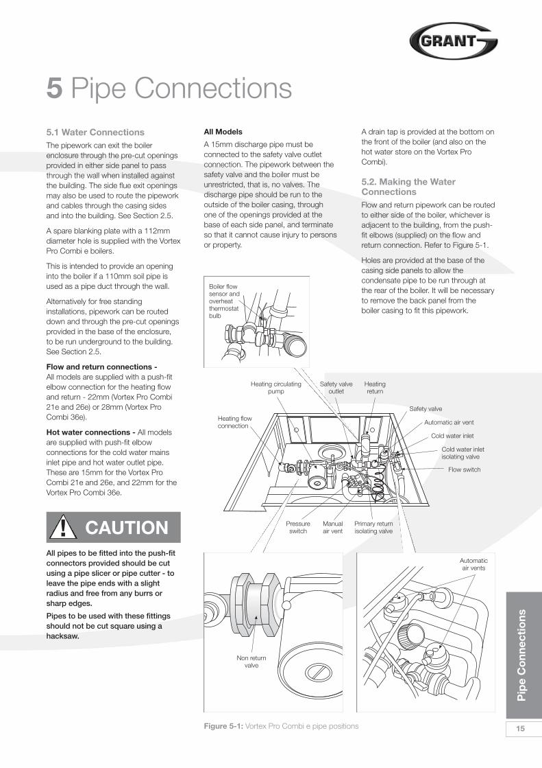
5.2. Making the WaterConnectionsFlow and return pipework can be routedto either side of the boiler, whichever isadjacent to the building, from the push-fit elbows (supplied) on the flow andreturn connection. Refer to Figure 5-1.
Holes are provided at the base of thecasing side panels to allow thecondensate pipe to be run through atthe rear of the boiler. It will be necessaryto remove the back panel from theboiler casing to fit this pipework.
All Models
A 15mm discharge pipe must beconnected to the safety valve outletconnection. The pipework between thesafety valve and the boiler must beunrestricted, that is, no valves. Thedischarge pipe should be run to theoutside of the boiler casing, throughone of the openings provided at thebase of each side panel, and terminateso that it cannot cause injury to personsor property.
Figure 5-1: Vortex Pro Combi e pipe positions
Heating flowconnection
Heating circulatingpump
Heatingreturn
Flow switch
Cold water inletisolating valve
Cold water inlet
Automatic air vent
Safety valve
Pressureswitch
Manualair vent
Primary returnisolating valve
Non returnvalve
Automaticair vents
Boiler flowsensor andoverheatthermostatbulb
Safety valveoutlet
5 Pipe Connections
16
Pip
e C
onn
ecti
ons
5.3 Domestic Hot WaterSystemTo maintain a longer and moreconsistent hot water temperature, a flowrestrictor is factory fitted to all modelsexcept the Vortex Pro Combi 36e, tolimit the flow rate to approximately 15litres / minute.
The flow restrictor is located in theoutlet side of the cold water inletisolating valve.
The incoming mains water pressureshould be between 1 and 8 bar toensure efficient operation.
If the pressure is above 8 bar a pressurereducing valve must be fitted.
The boiler may still operate down to apressure of 1.0 bar but with a reducedflow rate. The minimum flow rateneeded for the flow switch to operate is3 litres / minute.
To ensure economic use, the pipe runsbetween the boiler and hot taps shouldbe as short as possible and in 15mmcopper pipe or 22mm for the Vortex ProCombi 36e only. Where possible thepipework should be insulated to reduceheat loss.
All taps and mixing valves used in thedomestic hot water system must besuitable for operating at a mainspressure of up to 8 bar.
If required, a shower may be fitted in thedomestic hot water system. It isrecommended that thermostaticallycontrolled shower valves are used toprotect against a flow of water at toohigh a temperature. If a fixed head typeshower is used, no anti-syphonagedevices are required. If a loose orflexible head type shower is used, itmust be arranged so that the headcannot fall closer than 25mm above thetop of the bath, thereby preventingimmersion in the bath water. If this is notpracticable, an anti-syphonage devicemust be fitted at the point of the flexiblehose connection.
The supply of hot and cold mains waterdirect to a bidet is allowed (subject tolocal Water Undertaking requirements)provided that the bidet is of the over-rimflushing type. The outlets should beshrouded and unable to have atemporary hand held spray attached.Arrangements for antisyphonage are notnecessary.
If the hardness reading is found to be inthe medium to very hard range (theshaded area), it is essential that someform of water conditioner or softener isfitted to reduce scale formation withinthe combination boiler. Failure to do somay invalidate both the manufacturerswarranty and any extended warrantycovering the appliance.
The water conditioner or softenershould be fitted to the cold water supplyserving the appliance and in accordancewith the manufacturers instructions.Grant Engineering (UK) Ltd. cannot beheld responsible for any damage ormisuse caused by the fitting of anywater conditioning device.
Please protect the domestic hotwater system from harmful effects ofscale. Problems caused by the build-up of limescale are not covered underthe terms of the warranty.
Before the mains water supply pipe isconnected to the boiler, it should bethoroughly flushed out to avoid thedanger of dirt or foreign matter enteringthe boiler.
The mains water connection to theboiler must be the first connection fromthe mains supply.
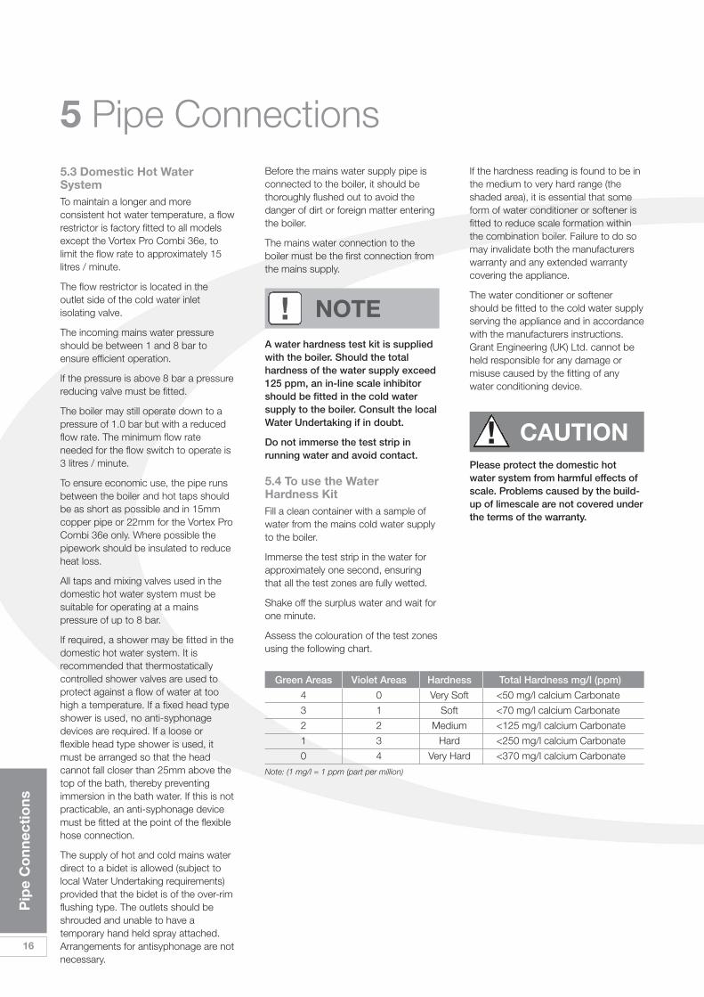
A water hardness test kit is suppliedwith the boiler. Should the totalhardness of the water supply exceed125 ppm, an in-line scale inhibitorshould be fitted in the cold watersupply to the boiler. Consult the localWater Undertaking if in doubt.
Do not immerse the test strip inrunning water and avoid contact.
5.4 To use the WaterHardness KitFill a clean container with a sample ofwater from the mains cold water supplyto the boiler.
Immerse the test strip in the water forapproximately one second, ensuringthat all the test zones are fully wetted.
Shake off the surplus water and wait forone minute.
Assess the colouration of the test zonesusing the following chart.
! CAUTION
! NOTE
Green Areas Violet Areas Hardness Total Hardness mg/l (ppm)
4 0 Very Soft <50 mg/l calcium Carbonate
3 1 Soft <70 mg/l calcium Carbonate
2 2 Medium <125 mg/l calcium Carbonate
1 3 Hard <250 mg/l calcium Carbonate
0 4 Very Hard <370 mg/l calcium Carbonate
Note: (1 mg/l = 1 ppm (part per million)
Co
nden
sate
D
isp
osa
l
17
6 Condensate Disposal6.1 General RequirementsWhen in condensing mode the GrantVortex PRO boilers produce condensatefrom the water vapour in the flue gases.This condensate is slightly acidic with aph value of around 3 (similar to vinegar).Provision must be made for the safe andeffective disposal of this condensate.
Condensate can be disposed of usingone of the following methods ofconnection:
Internal Connection (preferred option):
• Into an internal domestic wastesystem (from kitchen sink, washingmachine, etc.).
• Directly into the soil stack.
External Connection:
• Into an external soil stack
• Into an external drain or gulley
• into a rainwater hopper (that is partof a combined system where sewercaries both rainwater and foul water)
• purpose made soakaway.
All condensate disposal pipes must befitted with a trap - whether they areconnected internally or externally to adomestic waste system/soil stack or runexternally to a gully, hopper or soakaway.
6.2 ConnectionsConnections into a rainwater hopper,external drain or gulley should beterminated inside the hopper / drain /gulley below the grid level but above thewater level.
Condensate disposal pipes should notbe connected directly into rainwaterdownpipes or to waste / soil systemsconnected to septic tanks.
Condensate should not be dischargedinto ’grey water’ systems that re-usewater used in the home (not includingwater from toilets).
It should be noted that connection of acondensate pipe to the drain may besubject to local Building Controlrequirements.
6.3 PipeworkCondensate disposal pipework must beplastic (plastic waste or overflow pipe issuitable).
Copper or steel pipe is NOT suitableand MUST NOT be used.
Condensate disposal pipes should havea minimum ‘nominal’ diameter of 22mm(3/4”) - e.g. use 21.5mm ODpolypropylene overflow pipe.
Condensate disposal pipes must befitted with a fall (away from the boiler) ofat least 2.5° (~45mm fall per metre run).
Where it is not possible for the pipeto fall towards the point of discharge- either internally into a waste systemor externally to a gulley (e.g. forboilers installed in a basement), it willbe necessary to use a condensatepump.
Condensate disposal pipes should bekept as short as possible and thenumber of bends kept to a minimum.
Pipes should be adequately fixed toprevent sagging, i.e. at no more than0.5 metre intervals.
6.4 External PipeworkIdeally, external pipework, or pipeworkin unheated areas, should be avoided. Ifunavoidable, external pipework shouldbe kept as short as possible (less than 3metres) and 32mm waste pipe used tominimise the risk of ice blocking thepipe in freezing conditions.
The number of bends, fittings and jointson external pipes should be kept to aminimum to reduce the risk of trappingcondensate.
For a boiler installed in an unheatedarea such as an outhouse or garage,all condensate pipework should beconsidered as an ‘external’.
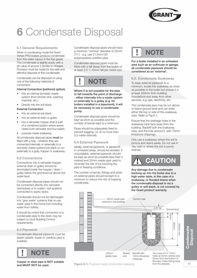
6.5. Condensate SoakawayTo keep external pipework to aminimum, locate the soakaway as closeas possible to the boiler but ensure it isat least 500mm from buildingfoundations and away from otherservices, e.g. gas, electricity, etc.
The condensate pipe may be run aboveor below ground level and can entereither the top or side of the soakawaytube. Refer to Fig.6-1.
Ensure that the drainage holes in thesoakaway tube face away from thebuilding. Backfill both the soakawaytube, and the hole around it, with 10mmlimestone chippings.
Only use a soakaway where the soil isporous and drains easily. Do not use inclay soils or where the soil is poorlydrained.
Any damage due to condensatebacking up into the boiler due to ahigh water table, in the case of asoakaway, or flooded drains whenthe condensate disposal is via agulley or soil stack, is not covered bythe Grant product warranty.
! NOTE
! NOTE
! NOTE
! CAUTION
Figure 6-1: Purpose made condensate soakaway
32mm waste pipeexternal to the building
Two rows of 3 x 12mmholes at 25mm centres and50mm from the bottom ofthe tube. Holes facing awayfrom the property.
Backfill with10mm limestonechippings
Sealedend
100mmplastic tube
Cement seal
Ground level2.5° fall
25mm
300mm
400mm
min.
18
Co
nden
sate
D
isp
osa
l
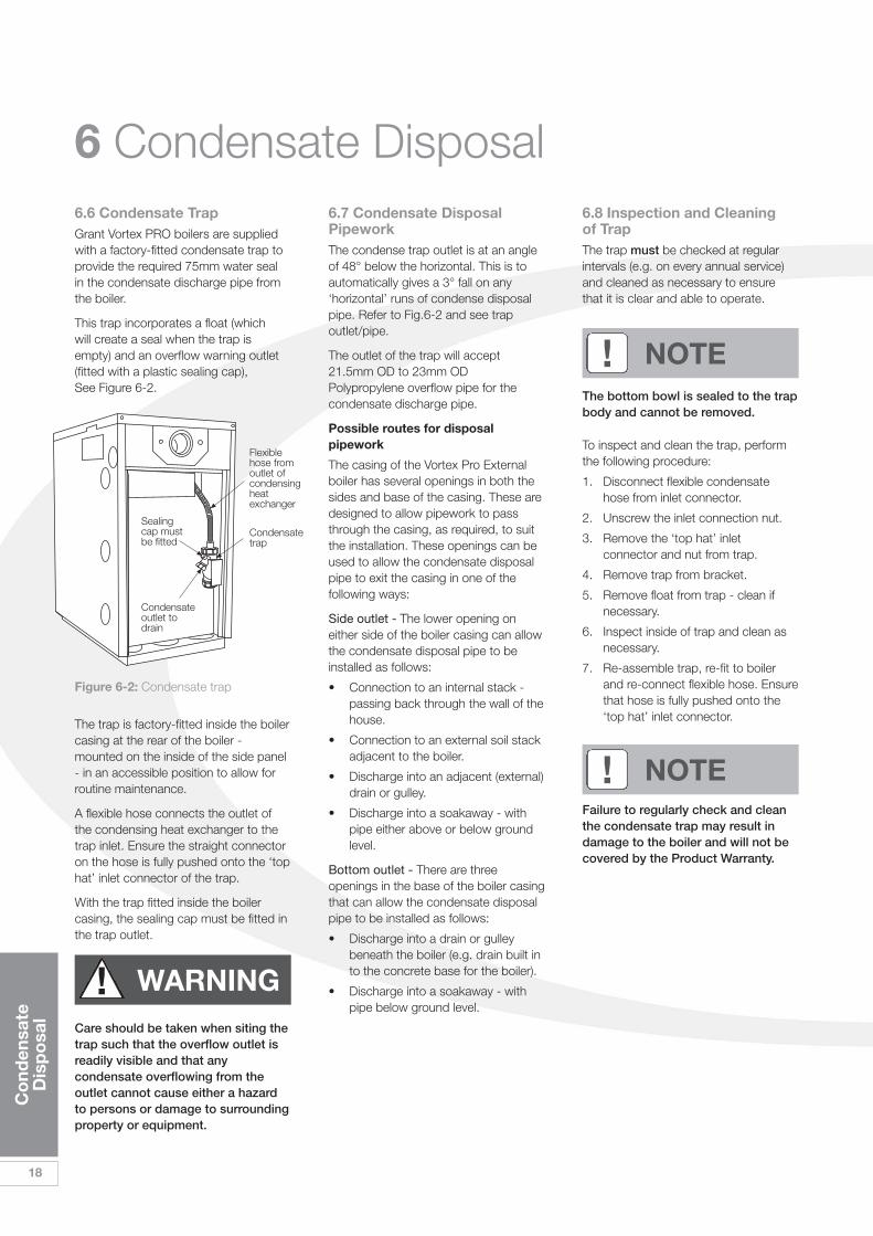
6.6 Condensate Trap Grant Vortex PRO boilers are suppliedwith a factory-fitted condensate trap toprovide the required 75mm water sealin the condensate discharge pipe fromthe boiler.
This trap incorporates a float (whichwill create a seal when the trap isempty) and an overflow warning outlet(fitted with a plastic sealing cap),See Figure 6-2.
6.8 Inspection and Cleaning of TrapThe trap must be checked at regularintervals (e.g. on every annual service)and cleaned as necessary to ensurethat it is clear and able to operate.
The bottom bowl is sealed to the trapbody and cannot be removed.
To inspect and clean the trap, performthe following procedure:
1. Disconnect flexible condensatehose from inlet connector.
2. Unscrew the inlet connection nut.
3. Remove the ‘top hat’ inletconnector and nut from trap.
4. Remove trap from bracket.
5. Remove float from trap - clean ifnecessary.
6. Inspect inside of trap and clean asnecessary.
7. Re-assemble trap, re-fit to boilerand re-connect flexible hose. Ensurethat hose is fully pushed onto the‘top hat’ inlet connector.
Failure to regularly check and cleanthe condensate trap may result indamage to the boiler and will not becovered by the Product Warranty.
6.7 Condensate DisposalPipeworkThe condense trap outlet is at an angleof 48° below the horizontal. This is toautomatically gives a 3° fall on any‘horizontal’ runs of condense disposalpipe. Refer to Fig.6-2 and see trapoutlet/pipe.
The outlet of the trap will accept21.5mm OD to 23mm ODPolypropylene overflow pipe for thecondensate discharge pipe.
Possible routes for disposalpipework
The casing of the Vortex Pro Externalboiler has several openings in both thesides and base of the casing. These aredesigned to allow pipework to passthrough the casing, as required, to suitthe installation. These openings can beused to allow the condensate disposalpipe to exit the casing in one of thefollowing ways:
Side outlet - The lower opening oneither side of the boiler casing can allowthe condensate disposal pipe to beinstalled as follows:
• Connection to an internal stack -passing back through the wall of thehouse.
• Connection to an external soil stackadjacent to the boiler.
• Discharge into an adjacent (external)drain or gulley.
• Discharge into a soakaway - withpipe either above or below groundlevel.
Bottom outlet - There are threeopenings in the base of the boiler casingthat can allow the condensate disposalpipe to be installed as follows:
• Discharge into a drain or gulleybeneath the boiler (e.g. drain built into the concrete base for the boiler).
• Discharge into a soakaway - withpipe below ground level.
The trap is factory-fitted inside the boilercasing at the rear of the boiler -mounted on the inside of the side panel- in an accessible position to allow forroutine maintenance.
A flexible hose connects the outlet ofthe condensing heat exchanger to thetrap inlet. Ensure the straight connectoron the hose is fully pushed onto the ‘tophat’ inlet connector of the trap.
With the trap fitted inside the boilercasing, the sealing cap must be fitted inthe trap outlet.
Care should be taken when siting thetrap such that the overflow outlet isreadily visible and that anycondensate overflowing from theoutlet cannot cause either a hazardto persons or damage to surroundingproperty or equipment.
6 Condensate Disposal
Figure 6-2: Condensate trap
! NOTE
! NOTE
! WARNING
Sealingcap mustbe fitted
Flexiblehose fromoutlet ofcondensingheatexchanger
Condensate trap
Condensateoutlet todrain
Sea
led
Sys
tem
s
19
7.1 System ModelsAll Grant Vortex Pro External Combi eboilers are supplied as part of a sealedsystem that complies with therequirements of BS 5449.
The maximum temperature of thecentral heating water is 78° C.
When designing a system, the pumphead, expansion vessel size, andradiator mean temperature areamongst the factors that must beconsidered. See Section 4.6.
The boilers are supplied with thefollowing items factory fitted:
• A diaphragm expansion vesselcomplying with BS 4814, pre-charged at 1.0 bar, size as follows:
10 litre for Vortex Pro Combi 21e
12 litre for Vortex Pro Combi 26e
14 litre for Vortex Pro Combi 36e.
• System pressure gauge, with anoperating range of 1 to 4 bar.
• Pressure relief safety valvecomplying with BS 6759 and set tooperate at 2.5 bar. The dischargepipe must be routed clear of theboiler to a drain, in such a mannerthat it can be seen, but cannotcause injury to persons or property.
• Automatic air vent, fitted to the topof the boiler, ensures the boiler isvented.
• Filling loop. This must be isolatedand disconnected after filling thesystem.
Refer to Section 4.5 for further details ofthe expansion vessel.
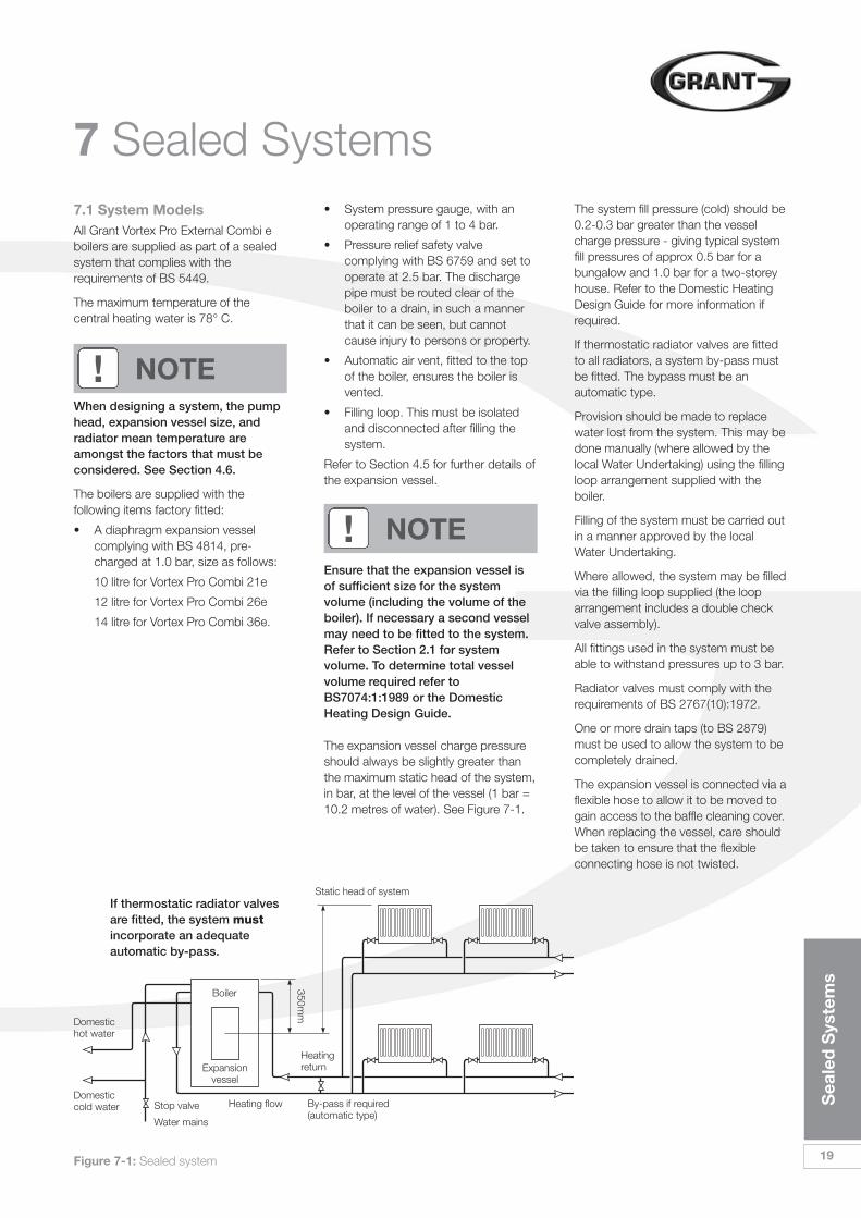
The expansion vessel charge pressureshould always be slightly greater thanthe maximum static head of the system,in bar, at the level of the vessel (1 bar =10.2 metres of water). See Figure 7-1.
The system fill pressure (cold) should be0.2-0.3 bar greater than the vesselcharge pressure - giving typical systemfill pressures of approx 0.5 bar for abungalow and 1.0 bar for a two-storeyhouse. Refer to the Domestic HeatingDesign Guide for more information ifrequired.
If thermostatic radiator valves are fittedto all radiators, a system by-pass mustbe fitted. The bypass must be anautomatic type.
Provision should be made to replacewater lost from the system. This may bedone manually (where allowed by thelocal Water Undertaking) using the fillingloop arrangement supplied with theboiler.
Filling of the system must be carried outin a manner approved by the localWater Undertaking.
Where allowed, the system may be filledvia the filling loop supplied (the looparrangement includes a double checkvalve assembly).
All fittings used in the system must beable to withstand pressures up to 3 bar.
Radiator valves must comply with therequirements of BS 2767(10):1972.
One or more drain taps (to BS 2879)must be used to allow the system to becompletely drained.
The expansion vessel is connected via aflexible hose to allow it to be moved togain access to the baffle cleaning cover.When replacing the vessel, care shouldbe taken to ensure that the flexibleconnecting hose is not twisted.
7 Sealed Systems
Figure 7-1: Sealed system
Static head of system
Heating flow
Heatingreturn
By-pass if required(automatic type)
350mm
Boiler
Expansionvessel
If thermostatic radiator valvesare fitted, the system mustincorporate an adequateautomatic by-pass.
Stop valve
Water mains
Domestichot water
Domesticcold water
! NOTE
Ensure that the expansion vessel isof sufficient size for the systemvolume (including the volume of theboiler). If necessary a second vesselmay need to be fitted to the system.Refer to Section 2.1 for systemvolume. To determine total vesselvolume required refer toBS7074:1:1989 or the DomesticHeating Design Guide.
! NOTE
20
Ele
ctri
cal
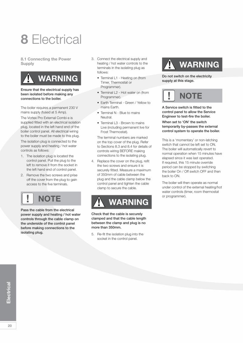
8 Electrical8.1 Connecting the PowerSupply
Ensure that the electrical supply hasbeen isolated before making anyconnections to the boiler.
The boiler requires a permanent 230 Vmains supply (fused at 5 Amp).
The Vortex Pro External Combi e issupplied fitted with an electrical isolationplug, located in the left hand end of theboiler control panel. All electrical wiringto the boiler must be made to this plug.
The isolation plug is connected to thepower supply and heating / hot watercontrols as follows:
1. The isolation plug is located thecontrol panel. Pull the plug to theleft to remove it from the socket inthe left hand end of control panel.
2. Remove the two screws and priseoff the cover from the plug to gainaccess to the five terminals.
Pass the cable from the electricalpower supply and heating / hot watercontrols through the cable clamp onthe underside of the control panelbefore making connections to theisolating plug.
3. Connect the electrical supply andheating / hot water controls to theterminals in the isolating plug asfollows:
• Terminal L1 - Heating on (from Timer, Thermostat or Programmer).
• Terminal L2 - Hot water on (from Programmer).
• Earth Terminal - Green / Yellow to mains Earth.
• Terminal N - Blue to mains Neutral.
• Terminal L3 - Brown to mains Live (including permanent live for Frost Thermostat).
The terminal numbers are markedon the top cover of the plug. Referto Sections 8.3 and 8.4 for details ofcontrols wiring BEFORE makingconnections to the isolating plug.
4. Replace the cover on the plug, refitthe two screws and ensure it issecurely fitted. Measure a maximumof 350mm of cable between theplug and the cable clamp below thecontrol panel and tighten the cableclamp to secure the cable.
Check that the cable is securelyclamped and that the cable lengthbetween the clamp and plug is nomore than 350mm.
5. Re-fit the isolation plug into thesocket in the control panel.
Do not switch on the electricitysupply at this stage.
A Service switch is fitted to thecontrol panel to allow the ServiceEngineer to test-fire the boiler.
When set to ‘ON’ the switchtemporarily by-passes the externalcontrol system to operate the boiler.
This is a ‘momentary’ or non-latchingswitch that cannot be left set to ON.The boiler will automatically revert tonormal operation when 15 minutes haveelapsed since it was last operated. If required, this 15 minute overrideperiod can be stopped by switchingthe boiler On / Off switch OFF and thenback to ON.
The boiler will then operate as normalunder control of the external heating/hotwater controls (timer, room thermostator programmer).
! WARNING
! WARNING
! WARNING
! NOTE
! NOTE
Ele
ctri
cal
21
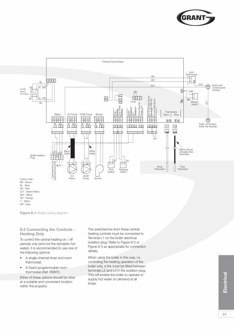
Figure 8-1: Boiler wiring diagram
4B
BL
BL
DR
DR
RD
GR
GR
BR
BR
G/Y
Timer
Colour code:BR - BrownBL - BlueRD - RedG/Y - Green/YellowBLK - BlackOR - OrangeY - YellowGR - Grey
On/OffSwitchC/W Neon
5B
1A
2A
1 2 3E N L
E N L E N LN L
4 5 6E N L
7 8 9E N L
10 1112E N L
OR
1314 1516 23 242526 27 28171819 20 21 22
Mains CH Pump DHW Pump Burner Low
Pre
ssS
witc
h
Flow
Sw
itch
CH
Tim
ed o
n
Tim
er N
eutr
alTi
mer
Liv
e
DH
WTi
med
on
Roo
m S
tat (
from
)
ThermistorsStore FlowE
xt F
rost
Sta
t (fro
m)
Ext
Fro
st S
tat (
to)
Boiler isolationPlug
Printed Circuit Board
CHPumpS
witc
hed
live
CH
Sw
itche
d liv
e D
HW
Y OR
G/Y
BL
RD Black
Cable
DHWPump
FlowSwitch
No No
PressureSwitch
StoreThermistor
FlowThermistor
Burner
WhiteCable
Black shroudindicates flowthermistor
Earth connectionboiler top bracket
LimitThermostat
Earth postcontrol panelchassis
Serviceswitch G
/Y
G/Y
2
C
8.2 Connecting the Controls -Heating OnlyTo control the central heating on / offperiods only (and not the domestic hotwater), it is recommended to use one ofthe following options:
• A single channel timer and roomthermostat.
• A Grant programmable roomthermostat (Ref. RSKIT).
Either of these options should be sitedat a suitable and convenient locationwithin the property.
The switched live from these centralheating controls must be connected toTerminal L1 on the boiler electricalisolation plug. Refer to Figure 8-2 orFigure 8-3 as appropriate for connectiondetails.
When using the boiler in this way, i.e.controlling the heating operation of theboiler only, a link must be fitted betweenterminals L2 and L3 in the isolation plug.This will enable the boiler to operate tosupply hot water on demand at alltimes.
22
Ele
ctri
cal
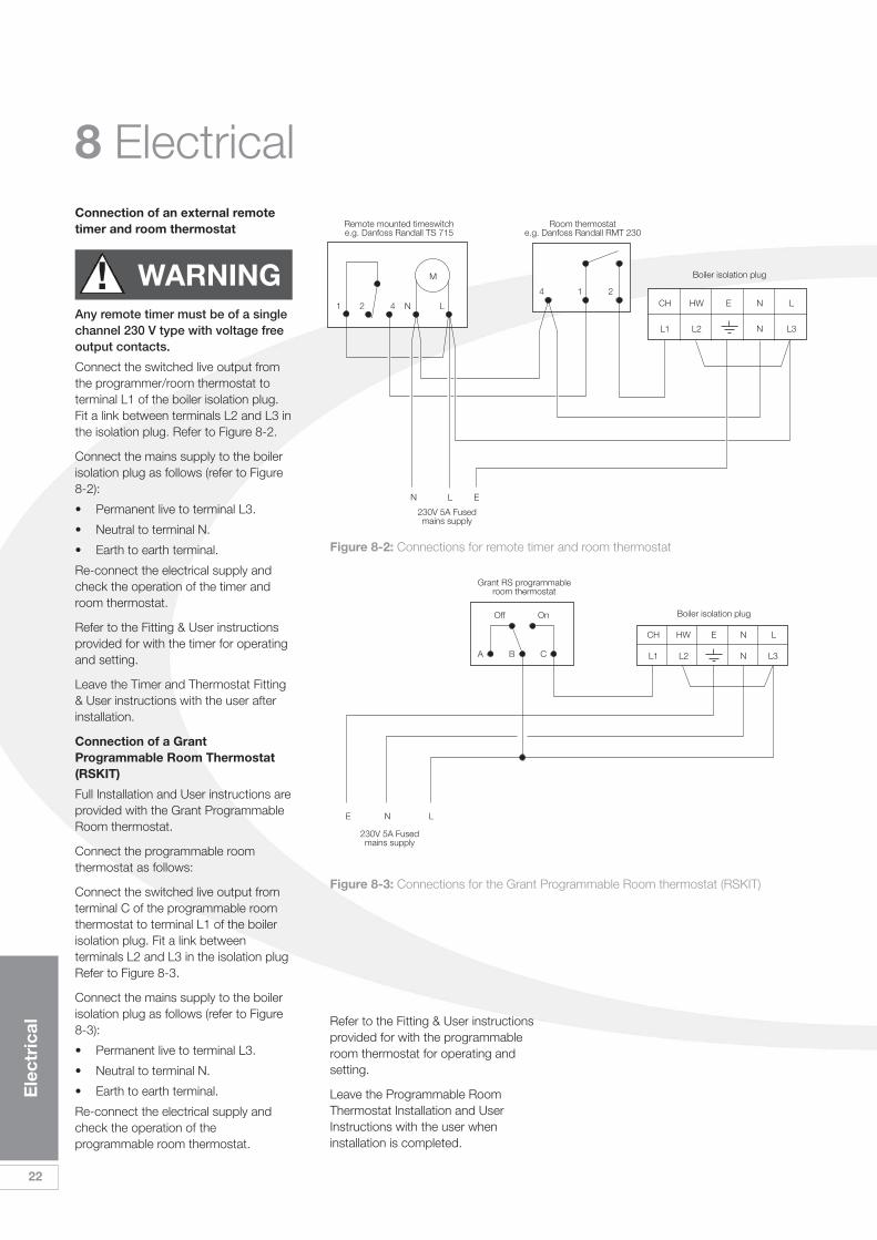
Connection of an external remotetimer and room thermostat
Any remote timer must be of a singlechannel 230 V type with voltage freeoutput contacts.
Connect the switched live output fromthe programmer/room thermostat toterminal L1 of the boiler isolation plug.Fit a link between terminals L2 and L3 inthe isolation plug. Refer to Figure 8-2.
Connect the mains supply to the boilerisolation plug as follows (refer to Figure8-2):
• Permanent live to terminal L3.
• Neutral to terminal N.
• Earth to earth terminal.
Re-connect the electrical supply andcheck the operation of the timer androom thermostat.
Refer to the Fitting & User instructionsprovided for with the timer for operatingand setting.
Leave the Timer and Thermostat Fitting& User instructions with the user afterinstallation.
Connection of a GrantProgrammable Room Thermostat(RSKIT)
Full Installation and User instructions areprovided with the Grant ProgrammableRoom thermostat.
Connect the programmable roomthermostat as follows:
Connect the switched live output fromterminal C of the programmable roomthermostat to terminal L1 of the boilerisolation plug. Fit a link betweenterminals L2 and L3 in the isolation plugRefer to Figure 8-3.
Connect the mains supply to the boilerisolation plug as follows (refer to Figure8-3):
• Permanent live to terminal L3.
• Neutral to terminal N.
• Earth to earth terminal.
Re-connect the electrical supply andcheck the operation of theprogrammable room thermostat.
Refer to the Fitting & User instructionsprovided for with the programmableroom thermostat for operating andsetting.
Leave the Programmable RoomThermostat Installation and UserInstructions with the user wheninstallation is completed.
! WARNING
8 Electrical
L1 L2 L3N
CH
A B C
Off On
N LE
HW E LN
Boiler isolation plug
Grant RS programmableroom thermostat
230V 5A Fusedmains supply
Figure 8-3: Connections for the Grant Programmable Room thermostat (RSKIT)
Figure 8-2: Connections for remote timer and room thermostat
L1 L2 L3N
CH4 1 2
1 2 4 N L
M
N L E
HW E LN
Boiler isolation plug
Room thermostate.g. Danfoss Randall RMT 230
Remote mounted timeswitche.g. Danfoss Randall TS 715
230V 5A Fusedmains supply
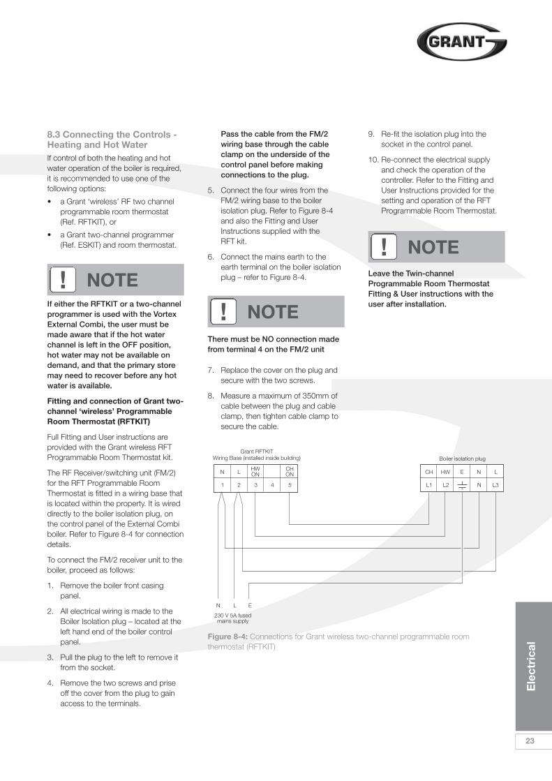
Figure 8-4: Connections for Grant wireless two-channel programmable roomthermostat (RFTKIT)
L1 L2 L3N2 3
N L
1
EN
230 V 5A fusedmains supply
L
54
CH HW LNE
Boiler isolation plugGrant RFTKIT
Wiring Base (installed inside building)
HWON
CHON
Ele
ctri
cal
23
8.3 Connecting the Controls -Heating and Hot WaterIf control of both the heating and hotwater operation of the boiler is required,it is recommended to use one of thefollowing options:
• a Grant ‘wireless’ RF two channelprogrammable room thermostat(Ref. RFTKIT), or
• a Grant two-channel programmer(Ref. ESKIT) and room thermostat.
If either the RFTKIT or a two-channelprogrammer is used with the VortexExternal Combi, the user must bemade aware that if the hot waterchannel is left in the OFF position,hot water may not be available ondemand, and that the primary storemay need to recover before any hotwater is available.
Fitting and connection of Grant two-channel ‘wireless’ ProgrammableRoom Thermostat (RFTKIT)
Full Fitting and User instructions areprovided with the Grant wireless RFTProgrammable Room Thermostat kit.
The RF Receiver/switching unit (FM/2)for the RFT Programmable RoomThermostat is fitted in a wiring base thatis located within the property. It is wireddirectly to the boiler isolation plug, onthe control panel of the External Combiboiler. Refer to Figure 8-4 for connectiondetails.
To connect the FM/2 receiver unit to theboiler, proceed as follows:
1. Remove the boiler front casingpanel.
2. All electrical wiring is made to theBoiler Isolation plug – located at theleft hand end of the boiler controlpanel.
3. Pull the plug to the left to remove itfrom the socket.
4. Remove the two screws and priseoff the cover from the plug to gainaccess to the terminals.
Pass the cable from the FM/2wiring base through the cableclamp on the underside of thecontrol panel before makingconnections to the plug.
5. Connect the four wires from theFM/2 wiring base to the boilerisolation plug. Refer to Figure 8-4and also the Fitting and UserInstructions supplied with the RFT kit.
6. Connect the mains earth to theearth terminal on the boiler isolationplug – refer to Figure 8-4.
There must be NO connection madefrom terminal 4 on the FM/2 unit
7. Replace the cover on the plug andsecure with the two screws.
8. Measure a maximum of 350mm ofcable between the plug and cableclamp, then tighten cable clamp tosecure the cable.
9. Re-fit the isolation plug into thesocket in the control panel.
10. Re-connect the electrical supplyand check the operation of thecontroller. Refer to the Fitting andUser Instructions provided for thesetting and operation of the RFTProgrammable Room Thermostat.
! NOTE
! NOTE
Leave the Twin-channelProgrammable Room ThermostatFitting & User instructions with theuser after installation.
! NOTE
24
Ele
ctri
cal
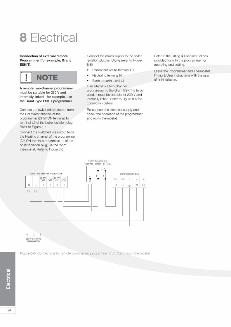
Figure 8-5: Connections for remote two-channel programmer (ESKIT) and room thermostat
8 ElectricalConnection of external remoteProgrammer (for example, GrantESKIT).
A remote two-channel programmermust be suitable for 230 V andinternally linked - for example, usethe Grant Type ESKIT programmer.
Connect the switched live output fromthe Hot Water channel of theprogrammer (DHW ON terminal) toterminal L2 of the boiler isolation plug.Refer to Figure 8-5.
Connect the switched live output fromthe Heating channel of the programmer(CH ON terminal) to terminal L1 of theboiler isolation plug, via the roomthermostat. Refer to Figure 8-5.
Connect the mains supply to the boilerisolation plug as follows (refer to Figure8-5):
• Permanent live to terminal L3
• Neutral to terminal N
• Earth to earth terminal
If an alternative two-channelprogrammer to the Grant ESKIT is to beused, it must be suitable for 230 V andinternally linked. Refer to Figure 8-5 forconnection details.
Re-connect the electrical supply andcheck the operation of the programmerand room thermostat.
Refer to the Fitting & User instructionsprovided for with the programmer foroperating and setting.
Leave the Programmer and ThermostatFitting & User instructions with the userafter installation.! NOTE
L1 L2 L3N1 2N L
EN
230 V 5A fusedmains supply
L
4
1 24
3
CH HW LNE
Grant two channel programmer Boiler isolation plug
Room therostat e.g.Danfoss Randall RMT 230
DHWOFF
HTGOFF
DHWON
HTGON
Ele
ctri
cal
25
8.4 Connecting a RemoteFrost Thermostat The boiler is fitted with a pre-set internalfrost protection thermostat. If either theair temperature around the boiler, or thewater temperature within the boiler, fallto below 5°C, then this thermostat willbe activated to protect the boiler fromfreezing.
If necessary, to protect the heatingsystem or any exposed heating systempipework, a remote frost thermostat canalso be connected to the boiler. Thisfrost thermostat should be sited withinthe house in such a place that it candetect any rise and fall in the ambienttemperature, that is, in a room with aradiator.
To connect a remote frost thermostat(for example, a Danfoss RandallRET230F), proceed as follows:
1. Remove the boiler door, top casingpanel and insulation from boiler.
2. Remove the two screws at top ofcontrol panel (in cross member).Hinge down control panel front.
3. From rear of control panel, carefullyfeed the cable from the Frostthermostat through the uppergrommet at the right hand end ofthe rear of the control panel.
4. Slacken the upper cable clamp onthe inside rear face of the controlpanel. Feed the cable through thecable clamp.
5. Connect wires to terminals oncontrol panel as follows:
• Frost thermostat Neutral (N) to terminal 21 on PCB connector.
• Frost thermostat Live (L) to terminal 24 on PCB connector.
• Frost thermostat Switched Live-ON (3) to terminal 23 on PCBconnector.
6. Refer to Figure 8-1 for typicalconnection of Remote FrostThermostat.
7. If an alternative Frost thermostat tothe Danfoss Randall RET230F isused, connect it in accordance withthe frost thermostat manufacturer’sinstructions.
8. This external frost thermostat willoperate in parallel with the internalfrost thermostat.
9. Re-tighten cable clamp. Re-fitcontrol panel front and secure usingthe two screws.
10. Re-connect the electrical supply.
26
Flue
Sys
tem
and
A
ir S
upp
ly
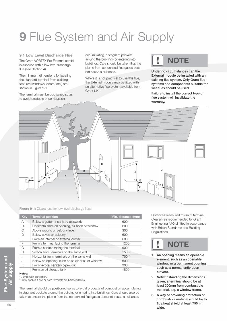
9 Flue System and Air Supply9.1 Low Level Discharge FlueThe Grant VORTEX Pro External combiis supplied with a low level dischargeflue (see Section 4).
The minimum dimensions for locatingthe standard terminal from buildingfeatures (windows, doors, etc.) areshown in Figure 9-1.
The terminal must be positioned so asto avoid products of combustion
accumulating in stagnant pocketsaround the buildings or entering intobuildings. Care should be taken that theplume from condensed flue gases doesnot cause a nuisance.
Where it is not practical to use this flue,the External module may be fitted withan alternative flue system available fromGrant UK.
Distances measured to rim of terminal.Clearances recommended by GrantEngineering (UK) Limited in accordancewith British Standards and BuildingRegulations.
1. An opening means an openableelement, such as an openablewindow, or a permanent openingsuch as a permanently openair vent.
2. Notwithstanding the dimensionsgiven, a terminal should be atleast 300mm from combustiblematerial, e.g. a window frame.
3. A way of providing protection ofcombustible material would be tofit a heat shield at least 750mmwide.
! NOTE
D
B
FEK
A
E
C
C
G J
H
I
Under no circumstances can theExternal module be installed with anexisting flue system. Only Grant fluesystems and components suitable forwet flues should be used.
Failure to install the correct type offlue system will invalidate thewarranty.
! NOTE
Figure 9-1: Clearances for low level discharge flues
Key Terminal position Min. distance (mm)
A Below a gutter or sanitary pipework 600*B Horizontal from an opening, air brick or window 600C Above ground or balcony level 300D Below eaves or balcony 600*E From an internal or external corner 600F From a terminal facing the terminal 1200G From a surface facing the terminal 600H Vertical from terminals on the same wall 1500I Horizontal from terminals on the same wall 750**J Below an opening, such as an air brick or window 600K From vertical sanitary pipework 300
From an oil storage tank 1800Notes:* 75mm with protection.** Only applies if one or both terminals are balanced flues.
The terminal should be positioned so as to avoid products of combustion accumulatingin stagnant pockets around the building or entering into buildings. Care should also betaken to ensure the plume from the condensed flue gases does not cause a nuisance.
Flue
Sys
tem
and
A
ir S
upp
ly
27
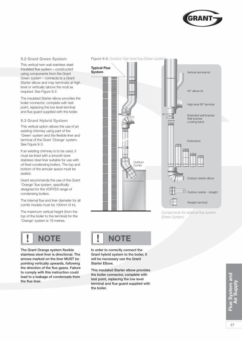
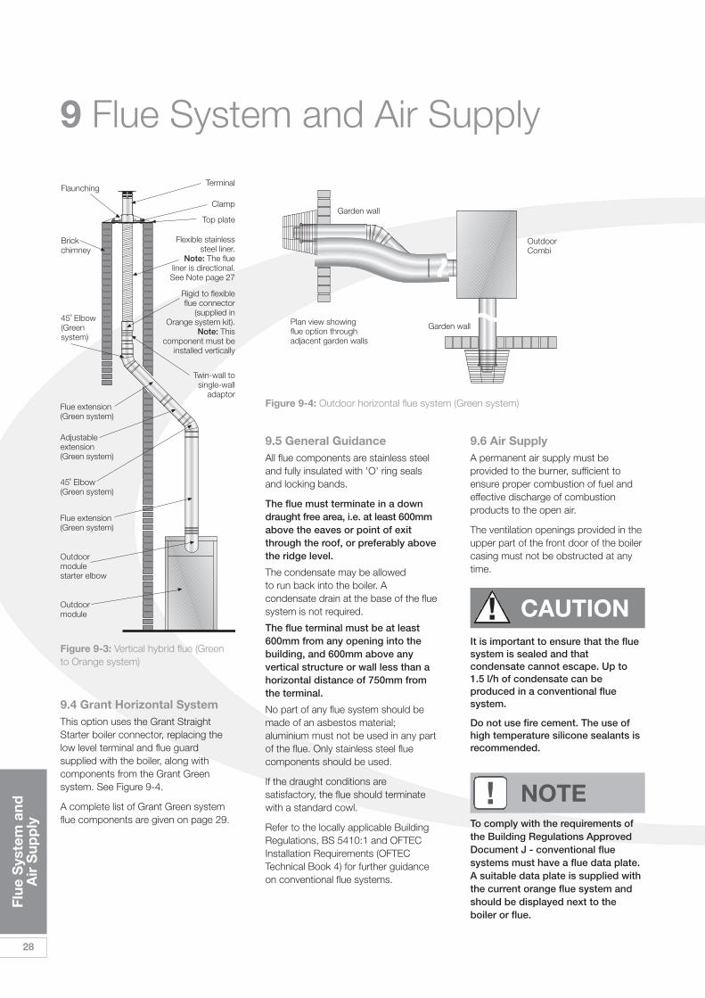
9.2 Grant Green SystemThis vertical twin wall stainless steelinsulated flue system – constructedusing components from the GrantGreen system – connects to a GrantStarter elbow and may terminate at highlevel or vertically (above the roof) asrequired. See Figure 9-2.
The insulated Starter elbow provides theboiler connector, complete with testpoint, replacing the low level terminaland flue guard supplied with the boiler.
9.3 Grant Hybrid SystemThis vertical option allows the use of anexisting chimney using part of the'Green' system and the flexible liner andterminal of the Grant 'Orange' system.See Figure 9-3.
If an existing chimney is to be used, itmust be lined with a smooth borestainless steel liner suitable for use withoil fired condensing boilers. The top andbottom of the annular space must besealed.
Grant recommends the use of the Grant‘Orange’ flue system, specificallydesigned for the VORTEX range ofcondensing boilers.
The internal flue and liner diameter for allcombi models must be 100mm (4 in).
The maximum vertical height (from thetop of the boiler to the terminal) for the‘Orange’ system is 19 metres.
Figure 9-2: Outdoor high level flue (Green system)
Components for external flue system(Green System)
Vertical terminal kit
45° elbow kit
Extensions
Outdoor starter elbow
Outdoor starter - straight
Straight terminal
High level 90º terminal
Extended wall bracketWall bracketLocking band
Typical FlueSystem
OutdoorCombi
The Grant Orange system flexiblestainless steel liner is directional. Thearrows marked on the liner MUST bepointing vertically upwards, followingthe direction of the flue gases. Failureto comply with this instruction couldlead to a leakage of condensate fromthe flue liner.
In order to correctly connect theGrant hybrid system to the boiler, itwill be necessary use the GrantStarter Elbow.
This insulated Starter elbow providesthe boiler connector, complete withtest point, replacing the low levelterminal and flue guard supplied withthe boiler.
! NOTE ! NOTE
28
Flue
Sys
tem
and
A
ir S
upp
ly
9.5 General GuidanceAll flue components are stainless steeland fully insulated with 'O' ring sealsand locking bands.
The flue must terminate in a downdraught free area, i.e. at least 600mmabove the eaves or point of exitthrough the roof, or preferably abovethe ridge level.
The condensate may be allowed to run back into the boiler. Acondensate drain at the base of the fluesystem is not required.
The flue terminal must be at least 600mm from any opening into thebuilding, and 600mm above anyvertical structure or wall less than ahorizontal distance of 750mm fromthe terminal.
No part of any flue system should bemade of an asbestos material;aluminium must not be used in any partof the flue. Only stainless steel fluecomponents should be used.
If the draught conditions aresatisfactory, the flue should terminatewith a standard cowl.
Refer to the locally applicable BuildingRegulations, BS 5410:1 and OFTECInstallation Requirements (OFTECTechnical Book 4) for further guidanceon conventional flue systems.
9.4 Grant Horizontal SystemThis option uses the Grant StraightStarter boiler connector, replacing thelow level terminal and flue guardsupplied with the boiler, along withcomponents from the Grant Greensystem. See Figure 9-4.
A complete list of Grant Green systemflue components are given on page 29.
9.6 Air SupplyA permanent air supply must beprovided to the burner, sufficient toensure proper combustion of fuel andeffective discharge of combustionproducts to the open air.
The ventilation openings provided in theupper part of the front door of the boilercasing must not be obstructed at anytime.
9 Flue System and Air Supply
OutdoorCombi
Garden wall
Garden wallPlan view showing flue option through adjacent garden walls
Figure 9-4: Outdoor horizontal flue system (Green system)
It is important to ensure that the fluesystem is sealed and thatcondensate cannot escape. Up to 1.5 l/h of condensate can beproduced in a conventional fluesystem.
Do not use fire cement. The use ofhigh temperature silicone sealants isrecommended.
! CAUTION
Figure 9-3: Vertical hybrid flue (Greento Orange system)
Flaunching
Brickchimney
45˚ Elbow(Greensystem)
Terminal
Clamp
Top plate
Twin-wall to single-wall
adaptor
Flue extension(Green system)
Adjustableextension(Green system)
45˚ Elbow(Green system)
Flue extension(Green system)
Outdoormodulestarter elbow
Outdoormodule
Flexible stainlesssteel liner.
Note: The flue liner is directional.See Note page 27
Rigid to flexible flue connector
(supplied in Orange system kit).
Note: Thiscomponent must be
installed vertically
To comply with the requirements ofthe Building Regulations ApprovedDocument J - conventional fluesystems must have a flue data plate.A suitable data plate is supplied withthe current orange flue system andshould be displayed next to theboiler or flue.
! NOTE
Co
mm
issi
oni
ng
29
IMPORTANTCABLE TO PLUG MUST BE SECURED IN CABLE CLAMP BELOW PANELMAXIMUM CABLE LENGTH BETWEEN PLUG AND CLAMP 350mm
WARNING 230V ISOLATE MAINS POWER SUPPLY BEFORE REMOVING COVER
1
2
N
3
N
L
Electricalconnection socket
Serviceswitch
Boilerthermostat
Pressuregauge
Boiler On / Off switch Indicator lightsOverheat reset button(under black cap)
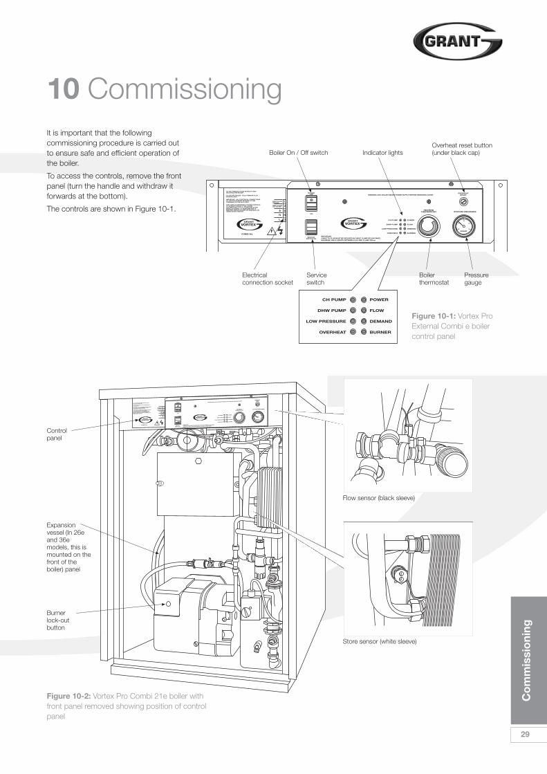
10 CommissioningIt is important that the followingcommissioning procedure is carried outto ensure safe and efficient operation ofthe boiler.
To access the controls, remove the frontpanel (turn the handle and withdraw itforwards at the bottom).
The controls are shown in Figure 10-1.
Figure 10-2: Vortex Pro Combi 21e boiler withfront panel removed showing position of controlpanel
Figure 10-1: Vortex ProExternal Combi e boilercontrol panel
IMPORTANTCABLE TO PLUG MUST BE SECURED IN CABLE CLAMP BELOW PANEL
MAXIMUM CABLE LENGTH BETWEEN PLUG AND CLAMP 350mm
WARNING 230V ISOLATE MAINS POWER SUPPLY BEFORE REMOVING COVER
1
2
N
3
N
L
Controlpanel
Expansionvessel (In 26eand 36emodels, this ismounted on thefront of theboiler) panel
Burnerlock-outbutton
Flow sensor (black sleeve)
Store sensor (white sleeve)
30
Co
mm
issi
oni
ng
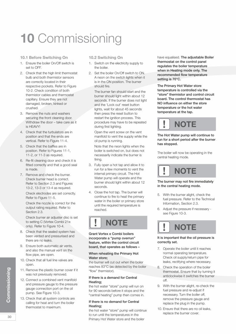
10 Commissioning10.1 Before Switching On1. Ensure the boiler On/Off switch is
set to OFF.
2. Check that the high limit thermostatbulb and both thermistor sensorsare correctly located in theirrespective pockets. Refer to Figure10-2. Check condition of boththermistor cables and thermostatcapillary. Ensure they are notdamaged, broken, kinked orcrushed.
3. Remove the nuts and washerssecuring the front cleaning door.Withdraw the door – take care as itis HEAVY!
4. Check that the turbulators are inposition and that the ends arevertical. Refer to Figure 11-4.
5. Check that the baffles are inposition. Refer to Figures 11-1, 11-2, or 11-3 as required.
6. Re-fit cleaning door and check it isfitted correctly and that a good sealis made.
7. Remove and check the burner.Check burner head is correct. Refer to Section 2.3 and Figures 13-2, 13-3 or 13-4 as required.
Check electrodes are set correctly.Refer to Figure 11-5.
Check the nozzle is correct for theoutput rating required. Refer toSection 2.3.
Check burner air adjuster disc is setto setting C (Vortex Combi 21eonly). Refer to Figure 10-4.
8. Check that the sealed system hasbeen vented and pressurised andthere are no leaks.
9. Ensure both automatic air vents,and also the manual vent on theflow pipe, are open.
10. Check that all fuel line valves areopen.
11. Remove the plastic burner cover if itwas not previously removed.
12. Connect a combined vent manifoldand pressure gauge to the pressuregauge connection port on the oilpump. See Figure 10-3.
13. Check that all system controls arecalling for heat and turn the boilerthermostat to maximum.
10.2 Switching On1. Switch on the electricity supply to
the boiler.
2. Set the boiler On/Off switch to ON.A neon on the switch lights when itis in the ON position. The burnershould fire.
The burner fan should start and theburner should light within about 12seconds. If the burner does not lightand the ‘Lock out’ reset buttonlights, wait for about 45 secondsthen press the reset button torestart the ignition process. Thisprocedure may have to be repeatedduring first lighting.
Open the vent screw on the ventmanifold to vent the supply while theoil pump is running.
Note that the neon lights when theboiler is switched on, but does notnecessarily indicate the burner isfiring.
3. Fully open a hot tap and allow it torun for a few moments to vent theinternal primary circuit. The HotWater pump will operate and theburner should light within about 12seconds.
4. Close the hot tap. The burner willcontinue to fire to heat the primarywater in the boiler or primary storeuntil the required temperature isreached.
Grant Vortex e Combi boilersincorporate a “pump overrun”feature, within the control circuitboard, that operates as follows –
When reheating the Primary HotWater store; the burner will cut out when the boilerreaches 83°C (as detected by the boiler“flow” thermistor).
If there is a demand for CentralHeating;the hot water “store” pump will run onfor 90 seconds before it stops and the“central heating” pump then comes in.
If there is no demand for CentralHeating; the hot water “store” pump will continueto run until the temperatures in thePrimary Hot Water store and the boiler
have equalised. The adjustable Boilerthermostat on the control panelregulates the boiler temperaturewhen in Heating mode only. Therecommended flow temperaturesetting is 70°C.
The Primary Hot Water storetemperature is controlled via the“store” thermistor and control circuitboard. The control thermostat hasNO influence on either the storetemperature or the hot watertemperature at the tap.
The Hot Water pump will continue torun for a short period after the burnerhas stopped.
The boiler will now be operating in thecentral heating mode.
The burner may not fire immediatelyin the central heating mode.
5. With the burner alight, check thefuel pressure. Refer to the TechnicalInformation, Section 2.3.
6. Adjust the pressure if necessary -see Figure 10-3.
It is important that the oil pressure iscorrectly set.
7. Operate the boiler until it reachesnormal operating temperature.Check oil supply/return pipe forleaks, rectifying where necessary.
8. Check the operation of the boilerthermostat. Ensure that by turning itanticlockwise it switches the burneroff.
9. With the burner alight, re-check thefuel pressure and re-adjust ifnecessary. Turn the boiler off,remove the pressure gauge andreplace the plug in the pump.
10. Ensure that there are no oil leaks,replace the burner cover.
! NOTE
! NOTE
! NOTE
! NOTE
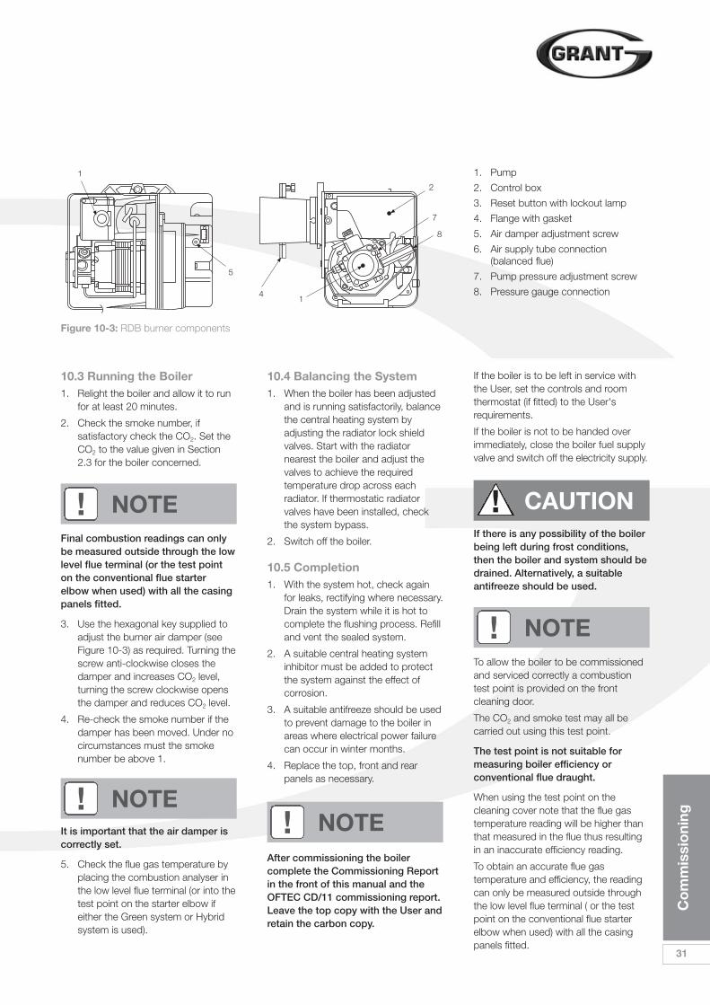
Co
mm
issi
oni
ng
31
10.3 Running the Boiler1. Relight the boiler and allow it to run
for at least 20 minutes.
2. Check the smoke number, ifsatisfactory check the CO2. Set theCO2 to the value given in Section2.3 for the boiler concerned.
Final combustion readings can onlybe measured outside through the lowlevel flue terminal (or the test pointon the conventional flue starterelbow when used) with all the casingpanels fitted.
3. Use the hexagonal key supplied toadjust the burner air damper (seeFigure 10-3) as required. Turning thescrew anti-clockwise closes thedamper and increases CO2 level,turning the screw clockwise opensthe damper and reduces CO2 level.
4. Re-check the smoke number if thedamper has been moved. Under nocircumstances must the smokenumber be above 1.
It is important that the air damper iscorrectly set.
5. Check the flue gas temperature byplacing the combustion analyser inthe low level flue terminal (or into thetest point on the starter elbow ifeither the Green system or Hybridsystem is used).
! NOTE
10.4 Balancing the System1. When the boiler has been adjusted
and is running satisfactorily, balancethe central heating system byadjusting the radiator lock shieldvalves. Start with the radiatornearest the boiler and adjust thevalves to achieve the requiredtemperature drop across eachradiator. If thermostatic radiatorvalves have been installed, checkthe system bypass.
2. Switch off the boiler.
10.5 Completion1. With the system hot, check again
for leaks, rectifying where necessary.Drain the system while it is hot tocomplete the flushing process. Refilland vent the sealed system.
2. A suitable central heating systeminhibitor must be added to protectthe system against the effect ofcorrosion.
3. A suitable antifreeze should be usedto prevent damage to the boiler inareas where electrical power failurecan occur in winter months.
4. Replace the top, front and rearpanels as necessary.
After commissioning the boilercomplete the Commissioning Reportin the front of this manual and theOFTEC CD/11 commissioning report.Leave the top copy with the User andretain the carbon copy.
If the boiler is to be left in service withthe User, set the controls and roomthermostat (if fitted) to the User'srequirements.
If the boiler is not to be handed overimmediately, close the boiler fuel supplyvalve and switch off the electricity supply.
If there is any possibility of the boilerbeing left during frost conditions,then the boiler and system should bedrained. Alternatively, a suitableantifreeze should be used.
To allow the boiler to be commissionedand serviced correctly a combustiontest point is provided on the frontcleaning door.
The CO2 and smoke test may all becarried out using this test point.
The test point is not suitable formeasuring boiler efficiency orconventional flue draught.
When using the test point on thecleaning cover note that the flue gastemperature reading will be higher thanthat measured in the flue thus resultingin an inaccurate efficiency reading.
To obtain an accurate flue gastemperature and efficiency, the readingcan only be measured outside throughthe low level flue terminal ( or the testpoint on the conventional flue starterelbow when used) with all the casingpanels fitted.
! NOTE! NOTE
! NOTE
! CAUTION
1. Pump
2. Control box
3. Reset button with lockout lamp
4. Flange with gasket
5. Air damper adjustment screw
6. Air supply tube connection(balanced flue)
7. Pump pressure adjustment screw
8. Pressure gauge connection
Figure 10-3: RDB burner components
1
5
4
2
7
8
1
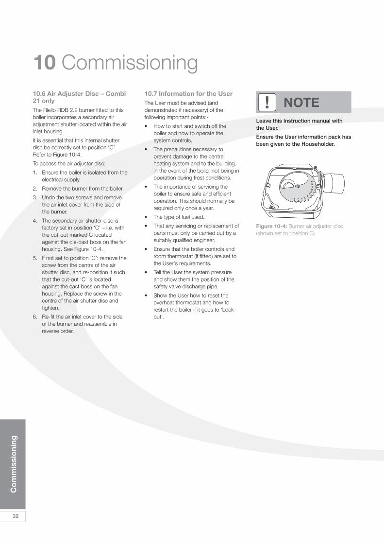
32
Co
mm
issi
oni
ng
10 Commissioning10.6 Air Adjuster Disc – Combi21 onlyThe Riello RDB 2.2 burner fitted to thisboiler incorporates a secondary airadjustment shutter located within the airinlet housing.
It is essential that this internal shutterdisc be correctly set to position ‘C’.Refer to Figure 10-4.
To access the air adjuster disc:
1. Ensure the boiler is isolated from theelectrical supply.
2. Remove the burner from the boiler.
3. Undo the two screws and removethe air inlet cover from the side ofthe burner.
4. The secondary air shutter disc isfactory set in position ‘C’ – i.e. withthe cut-out marked C locatedagainst the die-cast boss on the fanhousing. See Figure 10-4.
5. If not set to position ‘C’: remove thescrew from the centre of the airshutter disc, and re-position it suchthat the cut-out ‘C’ is locatedagainst the cast boss on the fanhousing. Replace the screw in thecentre of the air shutter disc andtighten.
6. Re-fit the air inlet cover to the sideof the burner and reassemble inreverse order.
10.7 Information for the UserThe User must be advised (anddemonstrated if necessary) of thefollowing important points:-
• How to start and switch off theboiler and how to operate thesystem controls.
• The precautions necessary toprevent damage to the centralheating system and to the building,in the event of the boiler not being inoperation during frost conditions.
• The importance of servicing theboiler to ensure safe and efficientoperation. This should normally berequired only once a year.
• The type of fuel used.
• That any servicing or replacement ofparts must only be carried out by asuitably qualified engineer.
• Ensure that the boiler controls androom thermostat (if fitted) are set tothe User's requirements.
• Tell the User the system pressureand show them the position of thesafety valve discharge pipe.
• Show the User how to reset theoverheat thermostat and how torestart the boiler if it goes to 'Lock-out'.
Leave this Instruction manual withthe User.
Ensure the User information pack hasbeen given to the Householder.
! NOTE
Figure 10-4: Burner air adjuster disc(shown set to position C)
Bo
iler
Ser
vici
ng
33
11 Boiler ServicingTo ensure efficient operation of theboiler it is recommended that it ischecked and serviced as necessary atregular intervals. The frequency ofservicing will depend upon the particularinstallation conditions and usage, but ingeneral once per year should beadequate.
Servicing and replacement of partsmust only be carried out by a suitablyqualified engineer.
Details of every service should beentered in the Service Log, in theBoiler Handbook.
This information may be required tovalidate the Grant extended warranty.
Before starting any work on theboiler, or fuel supply please read thehealth and safety information given inSection 14.
11.1 Checking beforeServicingThe following sequential checks shouldbe made before any servicing:
1. Check the flue terminal and ensure itis not blocked or damaged.
2. Run the boiler and check theoperation of its controls.
3. Ensure that all water / fuel systemconnections and fittings are sound.Remake any joints and check thetightness of any fittings that may beleaking.
4. The boiler is part of a sealed centralheating system; check the systempressure, check the operation of thepressure relief valve and check theexpansion vessel air charge.See Section 7.
5. Refill, vent and re-pressurisethe system as necessary.See Section 4.
6. Check that the ventilationopenings in the casing are clear.See Section 9.
7. Remove any sludge / water from thefuel tank by opening the sludgevalve at the lower end of the tank.
8. With the fuel supply valve closed,clean / replace the filter element andclean the filter bowl.
Braided flexible fuel supply hoses assupplied with the boiler should bereplaced annually when the boiler isserviced. If long-life hoses have beeninstalled, these should be inspectedannually. If in doubt replace the hoses.In any event, these hoses must bereplaced every five years.
Before servicing, set the boiler On /Off switch to Off, isolate theelectricity supply and close the fuelsupply valve.
Allow the boiler to cool.
The data label on the inside of thecase side panel will indicate the fuelused and the nozzle fitted.
11.2 Dismantling Prior toServicingThe procedure for dismantling the boileris as follows:
1. Remove the front panel.
2. Carefully lift up and remove theexpansion vessel from the boiler.
3. Remove the burner fixing nut (topof mounting flange) and withdrawthe burner.
If two flexible pipes are connected tothe burner, identify (mark ifnecessary) which is the suction andreturn if they are to be disconnected.
11.3 Cleaning the BoilerThe procedure for cleaning the boiler isas follows:
1. Remove the nuts and washerssecuring the front cleaning door andwithdraw the door. Take care -it is heavy.
2. Remove the baffles as shown inFigure 11-1, Figure 11-2 or Figure11-3, as appropriate.
3. Remove all deposits from the baffleplates and all the boiler internalsurfaces using a stiff brush andscraper if necessary.
4. Check the condition of the flue,clean as necessary.
5. Check the condition of the frontcleaning door seal and replace ifnecessary.
6. Replace the baffles, ensuring theyare correctly fitted. See Figure 11-1,Figure 11-2 or Figure 11-3, asappropriate. Pull out the spiralturbulators from the heat exchangertubes. See Figure 11-4.
7. Clean the turbulators using a stiffbrush.
8. Test the heat exchanger condensatedrain by pouring water into one ofthe lower tubes and observewhether the water discharges fromthe 22mm condensate outlet.Replace the turbulators.
9. Replace the front cleaning door,ensuring the seal is in goodcondition and secure it in positionwith the nuts and washerspreviously removed. Tighten to forma seal.
10. Remove the condensate trap andcheck that it is not blocked and isoperating correctly, i.e. the float isfree to move. Clean the trap andfloat as required.
11. Check that the boiler condensateoutlet is unobstructed. Clean ifnecessary.
The condensate trap and condensateoutlet must be checked on everyservice and cleaned as necessary.
! CAUTION
! WARNING
! WARNING
! NOTE
! NOTE
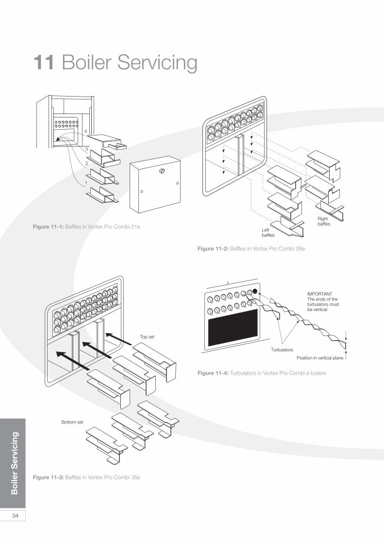
34
Bo
iler
Ser
vici
ng
11 Boiler Servicing
Figure 11-2: Baffles in Vortex Pro Combi 26e
Figure 11-1: Baffles in Vortex Pro Combi 21e
Figure 11-4: Turbulators in Vortex Pro Combi e boilers
Figure 11-3: Baffles in Vortex Pro Combi 36e
IMPORTANTThe ends of theturbulators mustbe vertical
Turbulators
Bottom set
Top set
Rightbaffles
Leftbaffles
4
3
2
1
Position in vertical plane
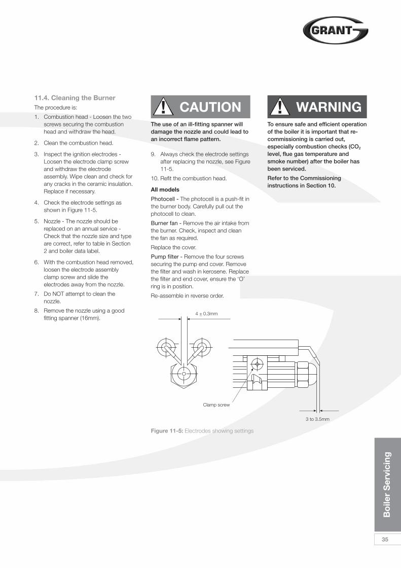
Bo
iler
Ser
vici
ng
35
11.4. Cleaning the BurnerThe procedure is:
1. Combustion head - Loosen the twoscrews securing the combustionhead and withdraw the head.
2. Clean the combustion head.
3. Inspect the ignition electrodes -Loosen the electrode clamp screwand withdraw the electrodeassembly. Wipe clean and check forany cracks in the ceramic insulation.Replace if necessary.
4. Check the electrode settings asshown in Figure 11-5.
5. Nozzle - The nozzle should bereplaced on an annual service -Check that the nozzle size and typeare correct, refer to table in Section2 and boiler data label.
6. With the combustion head removed,loosen the electrode assemblyclamp screw and slide theelectrodes away from the nozzle.
7. Do NOT attempt to clean thenozzle.
8. Remove the nozzle using a goodfitting spanner (16mm).
! CAUTIONThe use of an ill-fitting spanner willdamage the nozzle and could lead toan incorrect flame pattern.
9. Always check the electrode settingsafter replacing the nozzle, see Figure11-5.
10. Refit the combustion head.
All models
Photocell - The photocell is a push-fit inthe burner body. Carefully pull out thephotocell to clean.
Burner fan - Remove the air intake fromthe burner. Check, inspect and cleanthe fan as required.
Replace the cover.
Pump filter - Remove the four screwssecuring the pump end cover. Removethe filter and wash in kerosene. Replacethe filter and end cover, ensure the ‘O’ring is in position.
Re-assemble in reverse order.
To ensure safe and efficient operationof the boiler it is important that re-commissioning is carried out,especially combustion checks (CO2
level, flue gas temperature andsmoke number) after the boiler hasbeen serviced.
Refer to the Commissioninginstructions in Section 10.
! WARNING
Figure 11-5: Electrodes showing settings
4 +_ 0.3mm
3 to 3.5mm
Clamp screw
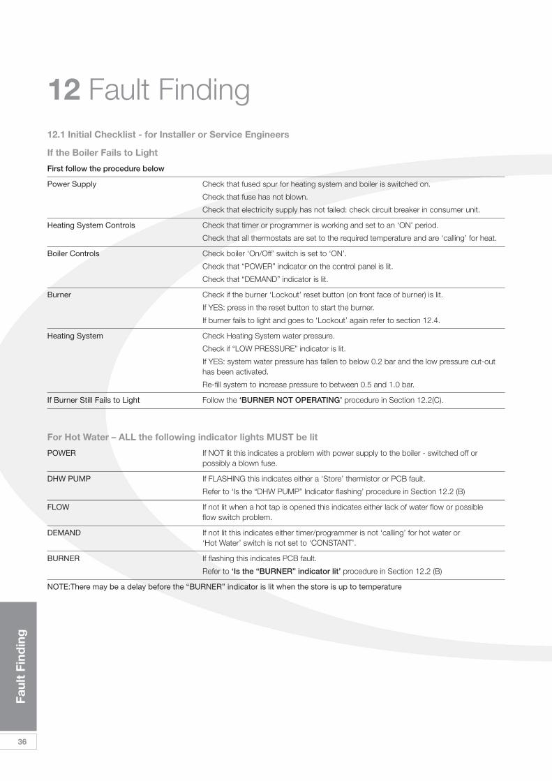
12 Fault Finding
36
Faul
t Fi
ndin
g
If the Boiler Fails to Light
First follow the procedure below
Power Supply Check that fused spur for heating system and boiler is switched on.
Check that fuse has not blown.
Check that electricity supply has not failed: check circuit breaker in consumer unit.
Heating System Controls Check that timer or programmer is working and set to an ‘ON’ period.
Check that all thermostats are set to the required temperature and are ‘calling’ for heat.
Boiler Controls Check boiler ‘On/Off’ switch is set to ‘ON’.
Check that “POWER” indicator on the control panel is lit.
Check that “DEMAND” indicator is lit.
Burner Check if the burner ‘Lockout’ reset button (on front face of burner) is lit.
If YES: press in the reset button to start the burner.
If burner fails to light and goes to ‘Lockout’ again refer to section 12.4.
Heating System Check Heating System water pressure.
Check if “LOW PRESSURE” indicator is lit.
If YES: system water pressure has fallen to below 0.2 bar and the low pressure cut-out has been activated.
Re-fill system to increase pressure to between 0.5 and 1.0 bar.
If Burner Still Fails to Light Follow the ‘BURNER NOT OPERATING’ procedure in Section 12.2(C).
For Hot Water – ALL the following indicator lights MUST be lit
POWER If NOT lit this indicates a problem with power supply to the boiler - switched off or possibly a blown fuse.
DHW PUMP If FLASHING this indicates either a ‘Store’ thermistor or PCB fault.
Refer to ‘Is the “DHW PUMP” Indicator flashing’ procedure in Section 12.2 (B)
FLOW If not lit when a hot tap is opened this indicates either lack of water flow or possible flow switch problem.
DEMAND If not lit this indicates either timer/programmer is not ‘calling’ for hot water or ‘Hot Water’ switch is not set to ‘CONSTANT’.
BURNER If flashing this indicates PCB fault.
Refer to ‘Is the “BURNER” indicator lit’ procedure in Section 12.2 (B)
NOTE:There may be a delay before the “BURNER” indicator is lit when the store is up to temperature
12.1 Initial Checklist - for Installer or Service Engineers
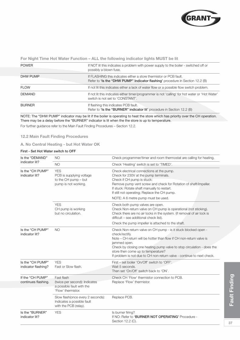
Faul
t Fi
ndin
g
37
For Night Time Hot Water Function – ALL the following indicator lights MUST be lit
POWER If NOT lit this indicates a problem with power supply to the boiler - switched off or possibly a blown fuse.
DHW PUMP If FLASHING this indicates either a store thermistor or PCB fault. Refer to ‘Is the “DHW PUMP” Indicator flashing’ procedure in Section 12.2 (B)
FLOW If not lit this indicates either a lack of water flow or a possible flow switch problem.
DEMAND If not lit this indicates either timer/programmer is not ‘calling’ for hot water or ‘Hot Water’ switch is not set to ‘CONSTANT’.
BURNER If flashing this indicates PCB fault. Refer to ‘Is the “BURNER” indicator lit’ procedure in Section 12.2 (B)
NOTE: The “DHW PUMP” indicator may be lit if the boiler is operating to heat the store which has priority over the CH operation.There may be a delay before the “BURNER” indicator is lit when the the store is up to temperature.
For further guidance refer to the Main Fault Finding Procedures – Section 12.2.
A. No Central Heating - but Hot Water OK
First - Set Hot Water switch to OFF
Is the “DEMAND” NO Check programmer/timer and room thermostat are calling for heating.indicator lit?
NO Check ‘Heating’ switch is set to ‘TIMED’.
Is the “CH PUMP” YES Check electrical connections at the pump.indicator lit? PCB is supplying voltage Check for 230V at the pump terminals.
to the CH pump – but Check if CH pump is stuck:pump is not working. Remove pump vent screw and check for Rotation of shaft/impeller.
If stuck: Rotate shaft manually to restart.If still not operating; Replace the CH pump.
NOTE: A 6 metre pump must be used.
YES Check both pump valves are open.CH pump is working Check Non-return valve on CH pump is operational (not sticking).but no circulation. Check there are no air locks in the system. (if removal of air lock is
difficult – see additional check list).
Check the pump impeller is attached to the shaft.
Is the “CH PUMP” NO Check Non-return valve on CH pump - is it stuck blocked open - indicator lit? check/rectify.
Note – CH return will be hotter than flow if CH non-return valve is jammed open.Check by closing one heating pump valve to stop circulation - does the store then come up to temperature?If problem is not due to CH non-return valve - continue to next check.
Is the “CH PUMP” YES First – set boiler ‘On/Off’ switch to ‘OFF’.indicator flashing? Fast or Slow flash. Wait 5 seconds.
Then set ‘On/Off’ switch back to ‘ON’.
If the “CH PUMP” Fast flash Check CH ‘Flow‘ thermistor connection to PCB.continues flashing. (twice per second): Indicates Replace ‘Flow’ thermistor.
a possible fault with the ‘Flow’ thermistor.
Slow flash(once every 2 seconds): Replace PCB.Indicates a possible faultwith the PCB (relay).
Is the “BURNER” YES Is burner firing?indicator lit? If NO: Refer to ‘BURNER NOT OPERATING’ Procedure -
Section 12.2 (C).
12.2 Main Fault Finding Procedures
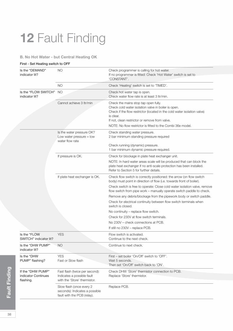
12 Fault Finding
38
Faul
t Fi
ndin
g
B. No Hot Water - but Central Heating OK
First - Set Heating switch to OFF
Is the “DEMAND” NO Check programmer is calling for hot water.indicator lit? If no programmer is fitted: Check ‘Hot Water’ switch is set to
‘CONSTANT’.
NO Check ‘Heating’ switch is set to ‘TIMED’.
Is the “FLOW SWITCH” NO Check hot water tap is open.indicator lit? Check water flow rate is at least 3 ltr/min.
Cannot achieve 3 ltr/min Check the mains stop tap open fully.Check cold water isolation valve in boiler is open.Check if the flow restrictor (located in the cold water isolation valve) is clear.If not, clean restrictor or remove from valve.
NOTE: No flow restrictor is fitted to the Combi 36e model.
Is the water pressure OK? Check standing water pressure.Low water pressure = low 2 bar minimum standing pressure required water flow rate
Check running (dynamic) pressure.1 bar minimum dynamic pressure required.
If pressure is OK. Check for blockage in plate heat exchanger unit.
NOTE: In hard water areas scale will be produced that can block the plate heat exchanger if no anti-scale protection has been installed. Refer to Section 5 for further details.
If plate heat exchanger is OK. Check flow switch is correctly positioned: the arrow (on flow switch body) must point in direction of flow (i.e. towards front of boiler).
Check switch is free to operate: Close cold water isolation valve, remove flow switch from pipe work – manually operate switch paddle to check.
Remove any debris/blockage from the pipework body or switch paddle.
Check for electrical continuity between flow switch terminals when switch is closed.
No continuity – replace flow switch.
Check for 230V at flow switch terminals.
No 230V – check connections at PCB.
If still no 230V – replace PCB.
Is the “FLOW YES Flow switch is activated.SWITCH” indicator lit? Continue to the next check.
Is the “DHW PUMP” NO Continue to next check.indicator lit?
Is the “DHW YES First – set boiler ‘On/Off’ switch to ‘OFF’.PUMP” flashing? Fast or Slow flash Wait 5 seconds.
Then set ‘On/Off’ switch back to ‘ON’.
If the “DHW PUMP” Fast flash (twice per second): Check DHW ‘Store’ thermistor connection to PCB.indicator Continues Indicates a possible fault Replace ‘Store’ thermistor.flashing. with the ‘Store’ thermistor.
Slow flash (once every 2 Replace PCB.seconds): Indicates a possible fault with the PCB (relay).
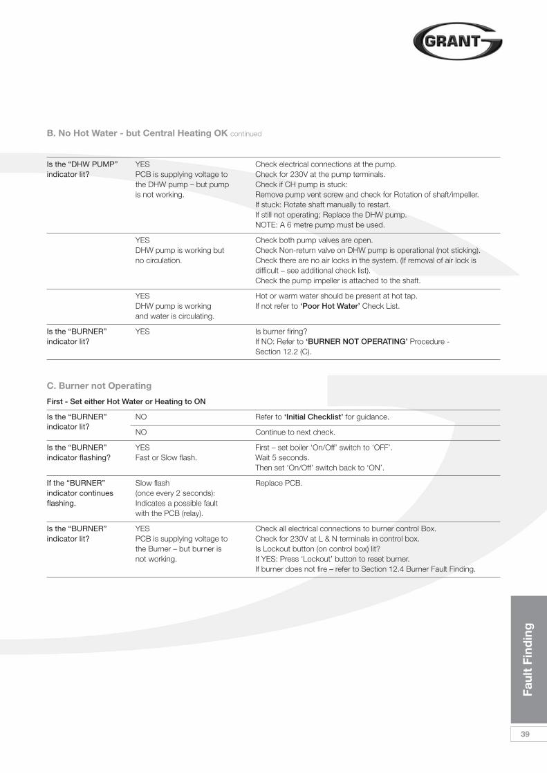
Faul
t Fi
ndin
g
39
C. Burner not Operating
First - Set either Hot Water or Heating to ON
Is the “BURNER” NO Refer to ‘Initial Checklist’ for guidance.indicator lit?
NO Continue to next check.
Is the “BURNER” YES First – set boiler ‘On/Off’ switch to ‘OFF’.indicator flashing? Fast or Slow flash. Wait 5 seconds.
Then set ‘On/Off’ switch back to ‘ON’.
If the “BURNER” Slow flash Replace PCB.indicator continues (once every 2 seconds):flashing. Indicates a possible fault
with the PCB (relay).
Is the “BURNER” YES Check all electrical connections to burner control Box.indicator lit? PCB is supplying voltage to Check for 230V at L & N terminals in control box.
the Burner – but burner is Is Lockout button (on control box) lit?not working. If YES: Press ‘Lockout’ button to reset burner.
If burner does not fire – refer to Section 12.4 Burner Fault Finding.
B. No Hot Water - but Central Heating OK continued
Is the “DHW PUMP” YES Check electrical connections at the pump.indicator lit? PCB is supplying voltage to Check for 230V at the pump terminals.
the DHW pump – but pump Check if CH pump is stuck:is not working. Remove pump vent screw and check for Rotation of shaft/impeller.
If stuck: Rotate shaft manually to restart.If still not operating; Replace the DHW pump.NOTE: A 6 metre pump must be used.
YES Check both pump valves are open.DHW pump is working but Check Non-return valve on DHW pump is operational (not sticking).no circulation. Check there are no air locks in the system. (If removal of air lock is
difficult – see additional check list).Check the pump impeller is attached to the shaft.
YES Hot or warm water should be present at hot tap.DHW pump is working If not refer to ‘Poor Hot Water’ Check List.and water is circulating.
Is the “BURNER” YES Is burner firing?indicator lit? If NO: Refer to ‘BURNER NOT OPERATING’ Procedure -
Section 12.2 (C).
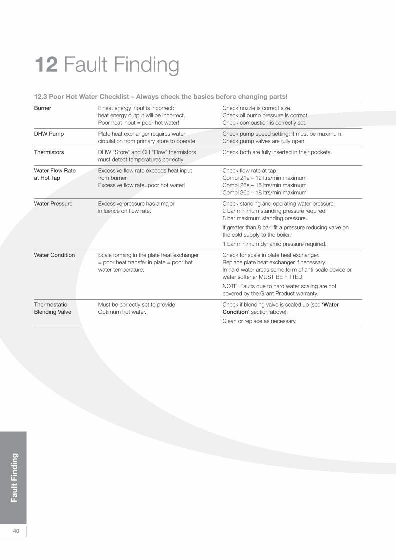
40
Faul
t Fi
ndin
g
12 Fault Finding12.3 Poor Hot Water Checklist – Always check the basics before changing parts!
Burner If heat energy input is incorrect: Check nozzle is correct size.heat energy output will be Incorrect. Check oil pump pressure is correct.Poor heat input = poor hot water! Check combustion is correctly set.
DHW Pump Plate heat exchanger requires water Check pump speed setting: it must be maximum.circulation from primary store to operate Check pump valves are fully open.
Thermistors DHW “Store“ and CH “Flow“ thermistors Check both are fully inserted in their pockets.must detect temperatures correctly
Water Flow Rate Excessive flow rate exceeds heat input Check flow rate at tap.at Hot Tap from burner Combi 21e – 12 ltrs/min maximum
Excessive flow rate=poor hot water! Combi 26e – 15 ltrs/min maximumCombi 36e – 18 ltrs/min maximum
Water Pressure Excessive pressure has a major Check standing and operating water pressure.influence on flow rate. 2 bar minimum standing pressure required
8 bar maximum standing pressure.
If greater than 8 bar: fit a pressure reducing valve on the cold supply to the boiler.
1 bar minimum dynamic pressure required.
Water Condition Scale forming in the plate heat exchanger Check for scale in plate heat exchanger.= poor heat transfer in plate = poor hot Replace plate heat exchanger if necessary.water temperature. In hard water areas some form of anti-scale device or
water softener MUST BE FITTED.
NOTE: Faults due to hard water scaling are not covered by the Grant Product warranty.
Thermostatic Must be correctly set to provide Check if blending valve is scaled up (see ‘WaterBlending Valve Optimum hot water. Condition’ section above).
Clean or replace as necessary.
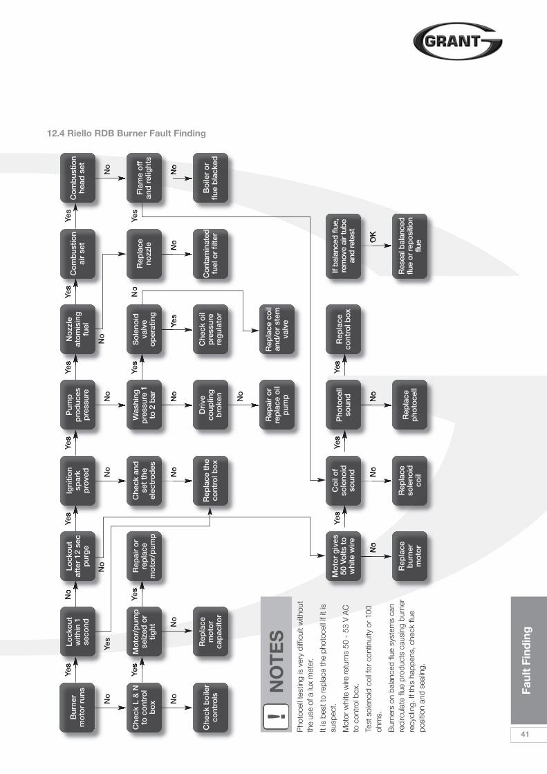
Faul
t Fi
ndin
g
41
12.4 Riello RDB Burner Fault Finding
Bur
ner
mo
tor
runs
Yes
Lock
out
with
in 1
seco
nd
No
Lock
out
af
ter
12 s
ecp
urg
e
Yes
Igni
tion
spar
k p
rove
d
Yes
Pum
pp
rod
uces
pre
ssur
e
Yes
Yes
Yes
Yes
No
zzle
ato
mis
ing
fuel
Yes
Co
mb
ustio
nai
r se
tC
om
bus
tion
head
set
Yes
No
Yes
No
No
No
No
No
No
No
No
No
Yes
Che
ck L
& N
to c
ont
rol
bo
x
Yes
Mo
tor/
pum
pse
ized
or
tight
Che
ck b
oile
rco
ntro
ls
Rep
lace
mo
tor
cap
acito
r
Yes
Rep
air
or
rep
lace
mo
tor/
pum
p
Che
ck a
ndse
t th
eel
ectr
od
es
Was
hing
pre
ssur
e 1
to 2
bar
Yes
So
leno
idva
lve
op
erat
ing
No
Rep
lace
nozz
leF
lam
e o
ff
and
rel
ight
s
Rep
lace
the
cont
rol b
ox
Dri
veco
uplin
gb
roke
n
Che
ck o
ilp
ress
ure
reg
ulat
or
No
No
No
No
OK
Rep
air
or
rep
lace
oil
pum
p
Rep
lace
co
ilan
d/o
r st
emva
lve
Pho
toce
llso
und
Co
il o
fso
leno
idso
und
Mo
tor
giv
es50
Vo
lts t
ow
hite
wire
Rep
lace
cont
rol b
ox
Con
tam
inat
edfu
el o
r fil
ter
If ba
lanc
ed fl
ue,
rem
ove
air t
ube
and
rete
st
Rep
lace
pho
toce
ll
Rep
lace
sole
noid
co
il
Rep
lace
bur
ner
mo
tor
Res
eal b
alan
ced
flue
or re
posi
tion
flue
Bo
iler
or
flue
bla
cked
Yes
No
No
!N
OT
ES
Pho
toce
ll te
stin
g is
ver
y di
fficu
lt w
ithou
tth
e us
e of
a lu
x m
eter
.
It is
bes
t to
repl
ace
the
phot
ocel
l if i
t is
susp
ect.
Mot
or w
hite
wire
retu
rns
50 -
53
V A
Cto
con
trol
box
.
Test
sol
enoi
d co
il fo
r co
ntin
uity
or
100
ohm
s.
Bur
ners
on
bala
nced
flue
sys
tem
s ca
nre
circ
ulat
e flu
e pr
oduc
ts c
ausi
ng b
urne
rre
cycl
ing.
If th
is h
appe
ns, c
heck
flue
posi
tion
and
seal
ing.
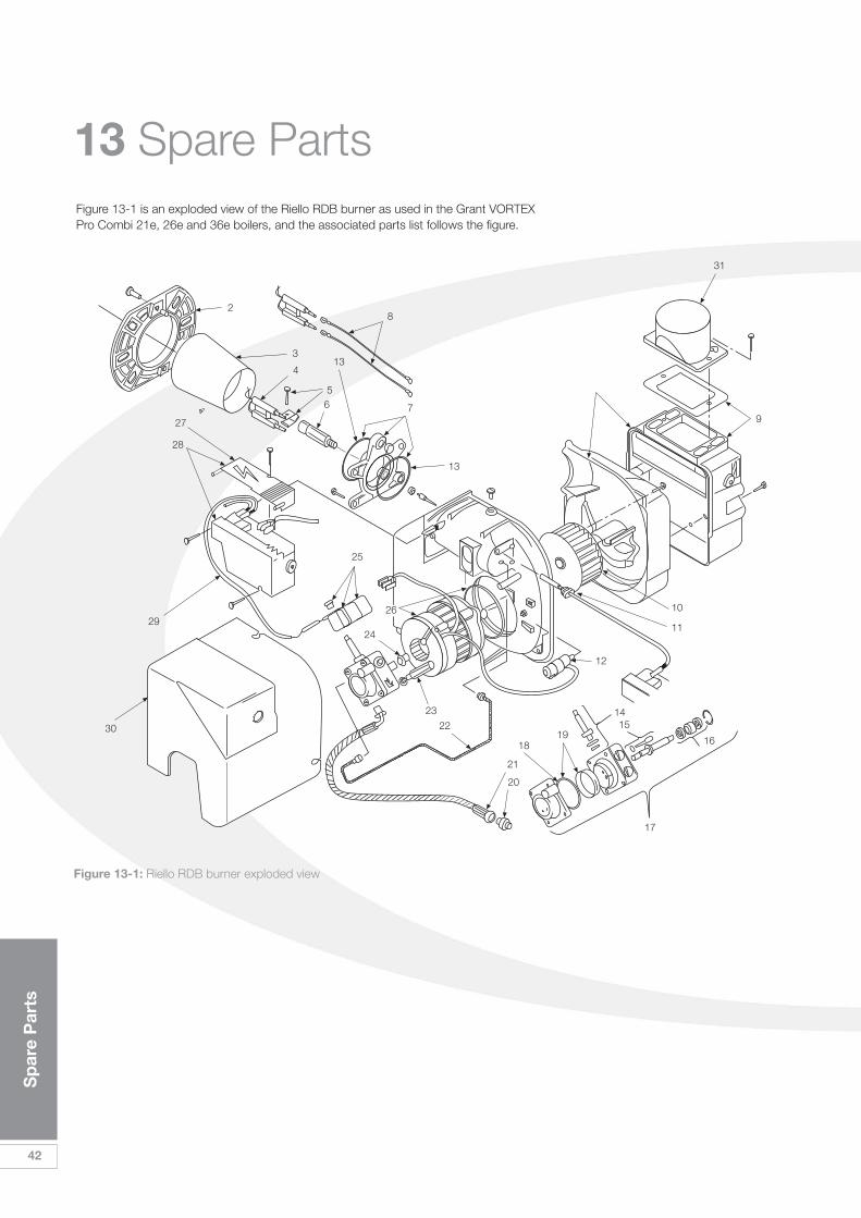
42
Sp
are
Par
ts
13 Spare PartsFigure 13-1 is an exploded view of the Riello RDB burner as used in the Grant VORTEXPro Combi 21e, 26e and 36e boilers, and the associated parts list follows the figure.
28
3
4
56
13
13
25
24
21
20
1819
1415
16
10
9
31
11
12
17
23
2230
26
727
28
29
Figure 13-1: Riello RDB burner exploded view
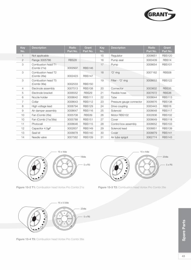
Sp
are
Par
ts
43
Key Description Riello Grant Key Description Riello Grant No. Part No. Part No. No. Part No. Part No.
1 Not applicable 15 Regulator 3008651 RBS120
2 Flange 3005786 RBS28 16 Pump seal 3000439 RBS14
3 Combustion head T1 17 Pump 3008654 RBS101(Combi 21e) 3002507 RBS146
3 Combustion head T2 18 ‘O’ ring 3007162 RBS08(Combi 26e) 3002423 RBS147
3 Combustion head T5 19 Filter - ‘O’ ring 3008653 RBS122(Combi 36e) 3002533 RBS150
4 Electrode assembly 3007513 RBS108 20 Connector 3003602 RBS35
5 Electrode bracket 3006552 RBS29 21 Flexible hose 3007672 RBS36
6 Nozzle holder 3008642 RBS111 22 Tube 3008644 RBS113
7 Collar 3008643 RBS112 23 Pressure gauge connector 3008876 RBS138
8 High voltage lead 3008794 RBS129 24 Drive coupling 3000443 RBS16
9 Air damper assembly 3008647 RBS116 25 Solenoid 3008648 RBS117
10 Fan (Combi 26e) 3005708 RBS39 26 Motor RBS102 3002836 RBS102
10 Fan (Combi 21e/36e) 3005788 RBS151 27 Cover 3008649 RBS118
11 Photocell 3008646 RBS115 28 Control box assembly 3008652 RBS103
12 Capacitor 4.5µF 3002837 RBS149 29 Solenoid lead 3008851 RBS139
13 Seal kit 3008878 RBS140 30 Cover 3008879 RBS141
14 Needle valve 3007582 RBS109 31 Air tube spigot 3062774 RBS143
Figure 13-2 T1: Combustion head Vortex Pro Combi 21e Figure 13-3 T2: Combustion head Vortex Pro Combi 26e
Figure 13-4 T5: Combustion head Vortex Pro Combi 36e
15 x 4dia
18dia
5 x R3
15 x 5.5dia
23dia
5 x R5
15 x 4dia
20dia
5 x R5
44
Hea
lth
and
Saf
ety
Info
rmat
ion
Under the Consumer Protection Act1987 and Section 6 of the Health &Safety at Work Act 1974, we arerequired to provide information onsubstances hazardous to health(COSHH Regulations 1988).
Adhesives, sealants and paints used inthe manufacture of the product arecured and present no known hazardswhen used in the manner for which theyare intended.
The following other materials arepresent in the product:
14.1 Insulation MaterialsMaterial Types: Ceramic fibre board,mineral wool.
Description: Rigid board, slabs,sleeves, gaskets, ropes.
Known Hazards: May cause temporaryirritation or rash to skin. High dust levelsmay irritate eyes and upper respiratorysystem.
Precautions: Avoid unnecessary orrough handling, or harsh abrasion ofboards. Normal handling and use ofmaterial should not produce high dustlevels.
Avoid inhalation, and contact with skinand eyes.
After handling always follow normalgood hygiene practices.
Protection: Use disposable gloves, facemask and eye protection.
First Aid: Eyes - If irritation occurs,wash eyes with copious amounts ofwater. If symptoms persist, seek
immediate medical advice.
Skin - If irritation occurs, wash underrunning water before washing with soapand water.
Inhalation - Remove to fresh air, drinkwater to clear throat and blow nose toremove dust/fibres.
Ingestion - Drink plenty of water.
14.2 Insulation MaterialsMaterial Types: Silicone elastomer.
Description: Sealant and adhesive.
Known Hazards: Irritation to eyes.
Precautions: Avoid inhalation of vapour,contact with eyes and prolonged orrepeated contact with skin.
After handling always follow normalgood hygiene practices.
Protection: Use eye protection. Rubberor plastic gloves should be worn whererepeated contact occurs and a facemask worn when working in confinedspaces.
First Aid: Eyes - Flush eyes with waterfor 15 minutes. Seek immediate medicalattention.
Skin - Wipe off and wash with soap andwater.
Inhalation - Remove to fresh air.
14.3 Kerosene and Gas OilFuels (mineral oils)Known Hazards: The effect of mineraloils on the skin vary according to theduration of exposure and the type of oil.
The lighter fractions remove theprotective grease naturally present onthe skin, leaving it dry, liable
to crack and more prone to damage bycuts, abrasions and irritant chemicals.
Skin rashes (Oil acne) most often onarms, but also on any part of the bodyin contact with oil or oily clothing.
Contact with fuel oils can causedermatitis.
Precautions: Avoid as far as possibleany skin contact with mineral oil or withclothing contaminated with mineral oil.
The use of a lanolin-based barrier creamis recommended, in conjunction withregular washing with
soap and rinsing with water to ensure alloil is removed from the skin.
Take care to prevent clothing, especiallyunderwear, from becomingcontaminated with oil.
Do not put oily rags or tools in pockets,especially trouser pockets.
Have first-aid treatment at once for aninjury, however slight.
Do not inhale any vapours from mineraloils.
14 Health and Safety Information
EC
Dec
lara
tio
no
f C
onf
orm
ity
45
We declare that the Grant Vortex range of Oil Boilers equipped with Riello RDB burners approved to EN 267: 1991 satisfy the requirementsof the following European Directives:-
1. 89/336/EEC - ElectromagneticCompatibility Directive
Referred to the generic standards EN 55014: 1993, EN 50082: 1: 1992
2. 73/23/EEC - Electrical EquipmentSafety Regulations Directive
Referred to the generic standard NO: 3260: The Electrical Equipment(Safety) Regulations: 1994
3. 92/42/EEC - Hot Water BoilerEfficiency Directive
Referred to the generic standard The Boiler (Efficiency) (Amendment) Regulations 1994 (SI 1994/3083).
In non-EU CountriesIn non-EU countries, dispose ofelectrical and electronic equipment andall surplus packaging in accordancewith national and regional regulations.
Complies with EC Low voltageElectromagnetic compatibility and Boiler efficiency Directives.
89/336/EEC73/23/EEC92/42/EEC
In EU CountriesThe following information is provided toenable regulatory compliance with theEuropean Union (EU) directivesidentified and any amendments made tothese directives when using electrical orelectronic equipment in EU countries.
Disposal of Electrical andElectronic EquipmentEuropean Union (EU) Directive2002/96/EC Waste Electrical andElectronic Equipment (WEEE).
Do not dispose of electrical or electronicequipment in landfill sites. In the EU, it isthe individual recipient’s responsibility toensure that discarded electrical orelectronic materials are collected andrecycled according to the requirementsof EU environmental law.
Disposal of Surplus PackagingEuropean Parliament and CouncilDirective 94/62/EC Packaging andPackaging Waste
Do not dispose of surplus packaging inlandfill sites. In the EU, it is the individualrecipient’s responsibility to ensure thatpackaging materials are collected andrecycled according to the requirementsof EU environmental law.
15 EC Declaration of Conformity
16 Warranty
46
War
rant
y
16.1 The Vortex Oil BoilerWarranty
Dear Customer You are now the proud owner of a GrantVortex Pro condensing Combi Boilerfrom Grant Engineering (UK) Ltd, thathas been designed to give years ofreliable, trouble free operation.
Grant Engineering (UK) Ltd. guaranteesthe manufacture of the boiler includingall electrical and mechanicalcomponents for a period of twelvemonths from the date of purchaseprovided the boiler is installed in fullaccordance with the installationinstructions provided. This will beextended to a period of two years if theboiler is registered with Grant UK withinthirty days of installation and it isserviced at twelve month intervals. SeeTerms and Conditions below.
IMPORTANTPlease register your Grant Vortex ProCombi boiler with Grant UK within thirtydays of installation. To do so visitwww.grantuk.com and follow the linksto the ‘Householder Zone’, where youcan register your boiler for a further oneyear warranty (giving two years from thedate of purchase). This does not affectyour statutory rights.
Breakdown during theManufacturer’s WarrantyIf your Grant boiler should fail within thefirst two years, you must contact GrantEngineering (UK) Ltd, who will arrangefor the repair under the terms of theirWarranty, providing that the boiler hasbeen correctly installed andcommissioned, serviced (if older thantwelve months) and the fault is not dueto tampering, running out of oil, oilcontamination, system watercontamination, misuse, or the failure ofany external components not suppliedby Grant UK (e.g. fire valve, motorisedvalve, etc.). This extended two yearwarranty only applies if the boiler isregistered with Grant UK within thirtydays of installation.
In the first Instance: Contact your installer or commissioningengineer to ensure that the fault doesnot lie with the system or any othercomponents, or any incorrect setting ofthe system controls.
If a Fault is Found: Ask your installer to contact GrantEngineering (UK) Ltd ServiceDepartment on 01380 736920 who willarrange for a qualified service engineerto attend to the fault.
Free of Charge Repairs: During the first two years no charge forparts or labour will be made providedthat the boiler has been installed andcommissioned correctly in accordancewith the manufacturer’s instructions, itwas registered with Grant UK withinthirty days of installation and, for boilersover twelve months old, details ofannual maintenance is available.
The following documents must be madeavailable to Grant UK on request:
• Proof of purchase
• CD10 Installation Completion form
• CD11 Commissioning report form
• Service documents (CD11 orequivalent document)
Chargeable Repairs:A charge may be made (if necessaryfollowing testing of parts at Grant UK) ifthe cause of the breakdown is due toany of the following:
• Faults caused by the plumbing or heating system, e.g.contamination of parts due tosystem contamination, debris ortrapped air.
• Faults due to incorrectly sizedexpansion vessel(s) or incorrectvessel charge pressure.
• Faults caused by external electricsand external components.
• The boiler has not beencommissioned, or serviced inaccordance with the installation andservicing manual.
• Problems caused by lack of oil orfaults with the oil supply system.
• The flue system has been incorrectlyfitted or does not meet installationrequirements.
• The boiler has been installed forover two years and no extendedwarranty cover has been taken.
Note: The nozzle supplied with theboiler is only covered for the period upto the time of the first service (twelvemonths).
Remember - before you contact Grant:Ensure the boiler has beencommissioned and serviced inaccordance with the Installation andservicing manual.
Ensure there is oil to supply the burner.
Ensure the problem is not being causedby the heating system or its controls.
Consult the boiler handbook forguidance.
! NOTEDo not wait until the fuel supply runsout before you order some more.Sludge in the bottom of the tank maybe drawn into the fuel lines. It isrecommended that the boiler isswitched off when the new supply isdelivered and that the fuel is allowedto settle for an hour before restartingthe boiler.
War
rant
y
47
6. This guarantee is not transferableunless sanctioned by the Company.
7. The Company will endeavour toprovide prompt service in theunlikely event of a problemoccurring, but cannot be heldresponsible for any consequencesof delay however caused.
8. This guarantee applies to Grantboilers installed on the UK mainland,Isle of Man and Channel Islandsonly. Provision of in-warranty coverelsewhere in the UK is subject toagreement with the Company.
9. All claims under this guarantee mustbe made to the Company prior toany work being undertaken.Invoices for call out/repair work byany third party will not be acceptedunless previously authorised by theCompany.
10. Proof of purchase and date ofinstallation, commissioning andservice documents must beprovided on request.
11. If a replacement boiler is suppliedunder the warranty (due to amanufacturing fault) the productwarranty continues from theinstallation date of the original boiler,and not from the installation date ofthe replacement.
Hard Water Advice If you live in a hard water area,protection against scaling must be givento the domestic hot water heatexchanger of your combination boiler.You should fit an appropriate scaleinhibitor or water softener as anybreakdown caused by water scalingis not covered by either themanufacturer’s guarantee orinsurance. Ask your installer for advice.
16.2 Extended WarrantyFor further peace of mind GrantEngineering (UK) Ltd offer the option toinsure all the components of your GrantVortex Pro Combi boiler for a furtherthree years, following on from the twoyear product warranty period. For asingle premium payment (inclusive ofInsurance Premium tax) you get fiveyears of protection against breakdowncosts. At the end of this period you willhave the opportunity to continue thiscover on an annual basis.
To access full details and an applicationform for this extended cover, first visitwww.grantuk.com.
Follow the links to the ‘HouseholderZone’, register your Grant Vortex proboiler for a further one year productwarranty (giving two years from the dateof purchase), and then download theextended warranty details andapplication form.
Please note that this special offer is onlyavailable if the application form issubmitted to Bluefin Insurance ServicesLtd. within three months of theinstallation date.
Terms of Manufacturer’s Guarantee1. The Company shall mean Grant
Engineering (UK) Limited.
2. The boiler is guaranteed for twoyears from the date of purchaseproviding that after twelve monthsthe annual service has beencompleted and the boiler registeredwith the Company within thirty daysof the installation date. Any workundertaken must be authorised bythe Company and carried out by anapproved service agent.
3. The shell (heat exchanger) of the oilboiler supplied by the Company iscovered by a five year parts onlyguarantee from the date ofpurchase subject to correctoperation of the boiler. Proof ofannual maintenance must beprovided.
4. This guarantee does not coverbreakdowns caused by incorrectinstallation, neglect, misuse,accident or failure to operate theboiler in accordance with themanufacturer’s instructions.
5. The boiler is registered with theCompany within thirty days ofinstallation. Failure to do so doesnot affect your statutory rights.

Notes
48
No
tes

No
tes
49
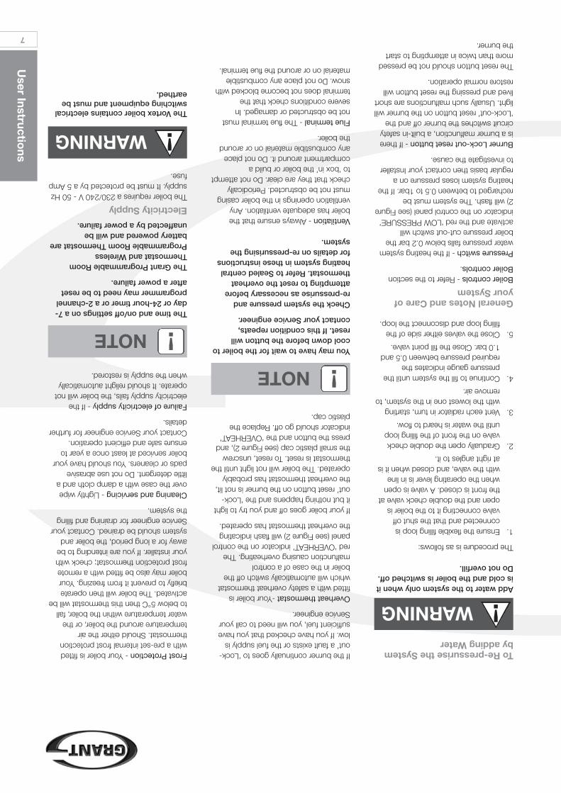
User Instructio
ns
7
To Re-pressurise the Systemby adding Water
You may have to wait for the boiler tocool down before the button willreset. If this condition repeats,contact your Service engineer.
Check the system pressure and re-pressurise as necessary beforeattempting to reset the overheatthermostat. Refer to Sealed centralheating system in these instructionsfor details on re-pressurising thesystem.
Ventilation- Always ensure that theboiler has adequate ventilation. Anyventilation openings in the boiler casingmust not be obstructed. Periodicallycheck that they are clear. Do not attemptto ‘box in’ the boiler or build acompartment around it. Do not placeany combustible material on or aroundthe boiler.
Flue terminal- The flue terminal mustnot be obstructed or damaged. Insevere conditions check that theterminal does not become blocked withsnow. Do not place any combustiblematerial on or around the flue terminal.
!NOTE
The time and on/off settings on a 7-day or 24-hour timer or a 2-channelprogrammer may need to be resetafter a power failure.
The Grant Programmable RoomThermostat and WirelessProgrammable Room Thermostat arebattery powered and will beunaffected by a power failure.
Electricity SupplyThe boiler requires a 230/240 V - 50 Hzsupply. It must be protected by a 5 Ampfuse.
!NOTE
Add water to the system only when itis cold and the boiler is switched off.Do not overfill.
The procedure is as follows:
1.Ensure the flexible filling loop isconnected and that the shut offvalve connecting it to the boiler isopen and the double check valve atthe front is closed. A valve is openwhen the operating lever is in linewith the valve, and closed when it isat right angles to it.
2.Gradually open the double checkvalve on the front of the filling loopuntil the water is heard to flow.
3.Vent each radiator in turn, startingwith the lowest one in the system, toremove air.
4.Continue to fill the system until thepressure gauge indicates therequired pressure between 0.5 and1.0 bar. Close the fill point valve.
5.Close the valves either side of thefilling loop and disconnect the loop.
General Notes and Care ofyour SystemBoiler controls- Refer to the sectionBoiler controls.
Pressure switch- If the heating systemwater pressure falls below 0.2 bar theboiler pressure cut-out switch willactivate and the red ‘LOW PRESSURE’indicator on the control panel (see Figure2) will flash. The system must berecharged to between 0.5 to 1bar. If theheating system loses pressure on aregular basis then contact your Installerto investigate the cause.
Burner Lock-out reset button- If thereis a burner malfunction, a built-in safetycircuit switches the burner off and the‘Lock-out’ reset button on the burner willlight. Usually such malfunctions are shortlived and pressing the reset button willrestore normal operation.
The reset button should not be pressedmore than twice in attempting to startthe burner.
If the burner continually goes to ‘Lock-out’ a fault exists or the fuel supply islow. If you have checked that you havesufficient fuel, you will need to call yourService engineer.
Overheat thermostat-Your boiler isfitted with a safety overheat thermostatwhich will automatically switch off theboiler in the case of a controlmalfunction causing overheating. Thered ‘OVERHEAT’ indicator on the controlpanel (see Figure 2) will flash indicatingthe overheat thermostat has operated.
If your boiler goes off and you try to lightit but nothing happens and the ‘Lock-out’ reset button on the burner is not lit,the overheat thermostat has probablyoperated. The boiler will not light until thethermostat is reset. To reset, unscrewthe small plastic cap (see Figure 2), andpress the button and the ‘OVERHEAT’indicator should go off. Replace theplastic cap.
Frost Protection- Your boiler is fittedwith a pre-set internal frost protectionthermostat. Should either the airtemperature around the boiler, or thewater temperature within the boiler, fallto below 5°C then this thermostat will beactivated. The boiler will then operatebriefly to prevent it from freezing. Yourboiler may also be fitted with a remotefrost protection thermostat; check withyour installer. If you are intending to beaway for a long period, the boiler andsystem should be drained. Contact yourService engineer for draining and fillingthe system.
Cleaning and servicing- Lightly wipeover the case with a damp cloth and alittle detergent. Do not use abrasivepads or cleaners. You should have yourboiler serviced at least once a year toensure safe and efficient operation.Contact your Service engineer for furtherdetails.
Failure of electricity supply- If theelectricity supply fails, the boiler will notoperate. It should relight automaticallywhen the supply is restored.
!WARNING
The Vortex boiler contains electricalswitching equipment and must beearthed.
!WARNING
6
User Instructio
ns
Points to Check if the BoilerFails to LightPerform the following checks if yourboiler fails to light:
1.Ensure that a fuse has not blown orthat the electricity supply has notfailed.
2.Check that the boiler On/Off switchis set to ON and that the POWERindicator on the control panel is lit.
3.Check that the timer or programmeris working and is in an ‘on’ period.
4.Check that all thermostats are set tothe desired setting and are ‘calling’for heat.
5.Check the DEMAND indicator onthe control panel is lit.
6.Check if the burner ‘Lock-out’ resetbutton (on the front face of theburner) is lit. See Figure 1.
7.If it is, press in the button to startthe burner. If the burner fails to lightand goes to ‘Lock-out’ again, checkthat you have sufficient fuel in thestorage tank and the fuel supplyvalves are open.
8.Check that remote fire valve has not‘tripped’. Reset if necessary.
9.Check to see if the overheatthermostat has operated. SeeOverheat thermostat under Generalnotes and care of your system.
10.Check the heating system waterpressure. If it falls below 0.2 bar theboiler low pressure cut-out will beactivated, cutting power to theburner, and the red ‘LOWPRESSURE’ indicator on the controlpanel (see Figure 2) will flash. Thesystem must be re-charged tobetween 0.5 and 1 bar. If theheating system loses pressure on aregular basis then contact yourInstaller to investigate the cause.
If the burner still fails to light aftercarrying out these checks then a faultexists. Switch off the electricity supplyto the boiler and contact your serviceengineer.
Domestic Hot Water SystemThe boiler will supply domestic hotwater whenever a hot tap is opened,provided the boiler On/Off switch is setto ON. If a 2-channel programmer isfitted, the Hot water setting on theprogrammer must be ‘on’ for the boilerto provide continuous hot water.
‘Night time’ Hot Water FunctionThis is a feature built in to your boilerallowing a limited amount of hot waterto be drawn off during periods wheneither the hot water programmerchannel is ‘off’ (for example, during thenight). When a hot tap is opened duringthis period, the flow switch activates thehot water store pump and the incomingmains cold water is heated usingwhatever heat is present in the primarystore. The burner will not fire and so theheat in the store will gradually be usedup and the hot water temperature willreduce with time.
If a 2-channel programmer is fitted, theHot water setting on the programmermust be ‘on’ for the boiler to providecontinuous hot water when the HotWater switch is set to TIMED.
If the heating system water pressurefalls below 0.2 bar the boiler lowpressure cut-out will be activated,cutting power to the burner, and the red‘LOW PRESSURE’ indicator on thecontrol panel (see Figure 2) will flash.The system must be re-charged tobetween 0.5 and 1 bar. If the heatingsystem loses pressure on a regularbasis then contact your Installer toinvestigate and rectify the cause.
The boiler is fitted with an automatic airvent which removes air trapped in theboiler. Any air trapped in the radiatorsneeds to be removed by venting theradiators via the vent screw at the top ofeach radiator. Only vent a radiator if thetop is cool when the bottom is hot.Venting will reduce the system pressure,as indicated on the pressure gauge, soonly vent when necessary and checkthe system pressure as mentionedabove.
User Instructions
The flow of water from the taps (hotor cold) depends on the mainspressure, and in some homes it maynot be possible to use more than onetap at a time.
Sealed Central HeatingSystemThe boiler operates on a sealed heatingsystem. Your installer will havepressurised the system and set thewhite pointer on the pressure gauge (seeFigure 2) to indicate a system pressure(when cold) of usually between 0.5 and1.0 bar. Do notadjust this pointer.
The white pointer indicates the actualsystem pressure which will increaseslightly when the boiler is operating. If thewhite pointer falls below the red pointer(when the boiler is switched off and cold),you should contact your Installer tocheck the heating system for leaks.
!NOTE
Your sealed system may incorporatea ‘Top-up’ vessel. Advice on how touse this should be obtained fromyour installer.
The boiler is fitted with a safety (orpressure relief) valve to automaticallyrelease excess pressure from thesystem. If the water or steam is emittedfrom the end of the safety valvedischarge pipe, switch off the boiler andcontact your Installer or ServiceEngineer.
The Expansion vessel air charge mustbe checked annually. Failure to maintainan adequate air charge in the vesselmay invalidate the warranty.
!NOTE
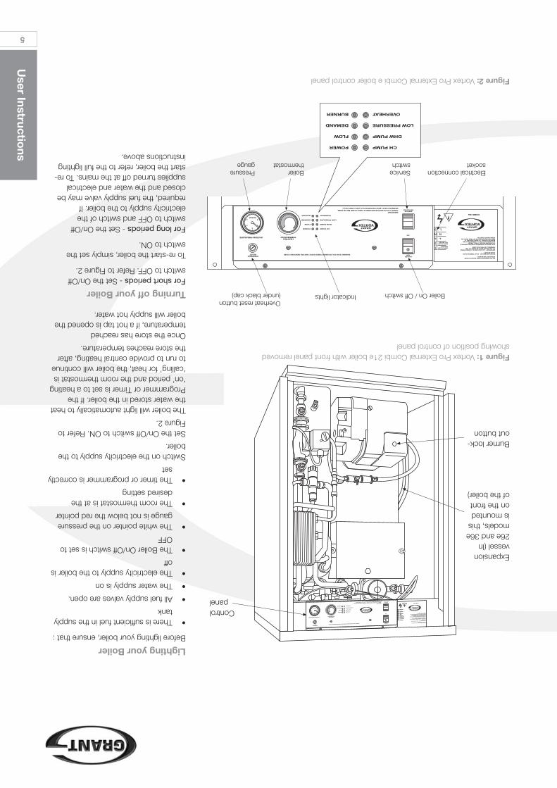
User Instructio
ns
5
Lighting your BoilerBefore lighting your boiler, ensure that :
•There is sufficient fuel in the supplytank
•All fuel supply valves are open.
•The water supply is on
•The electricity supply to the boiler isoff
•The Boiler On/Off switch is set toOFF
•The white pointer on the pressuregauge is not below the red pointer
•The room thermostat is at thedesired setting
•The timer or programmer is correctlyset
Switch on the electricity supply to theboiler.
Set the On/Off switch to ON. Refer toFigure 2.
The boiler will light automatically to heatthe water stored in the boiler. If theProgrammer or Timer is set to a heating‘on’ period and the room thermostat is‘calling’ for heat, the boiler will continueto run to provide central heating, afterthe store reaches temperature.
Once the store has reachedtemperature, if a hot tap is opened theboiler will supply hot water.
Turning off your BoilerFor short periods- Set the On/Offswitch to OFF. Refer to Figure 2.
To re-start the boiler, simply set theswitch to ON.
For long periods- Set the On/Offswitch to OFF and switch of theelectricity supply to the boiler. Ifrequired, the fuel supply valve may beclosed and the water and electricalsupplies turned off at the mains. To re-start the boiler, refer to the full lightinginstructions above.
Figure 2:Vortex Pro External Combi e boiler control panel
IMPORTANTCABLE TO PLUG MUST BE SECURED IN CABLE CLAMP BELOW PANEL
MAXIMUM CABLE LENGTH BETWEEN PLUG AND CLAMP 350mm
WARNING 230V ISOLATE MAINS POWER SUPPLY BEFORE REMOVING COVER
1
2
N
3
N
L
Figure 1:Vortex Pro External Combi 21e boiler with front panel removedshowing position of control panel
Expansionvessel (In26e and 36emodels, thisis mountedon the frontof the boiler)
Burner lock-out button
Controlpanel
IMPORTANTCABLE TO PLUG MUST BE SECURED IN CABLE CLAMP BELOW PANELMAXIMUM CABLE LENGTH BETWEEN PLUG AND CLAMP 350mm
WARNING 230V ISOLATE MAINS POWER SUPPLY BEFORE REMOVING COVER
1
2
N
3
N
L
Electrical connectionsocket
Serviceswitch
Boilerthermostat
Pressuregauge
Boiler On / Off switchIndicator lightsOverheat reset button(under black cap)
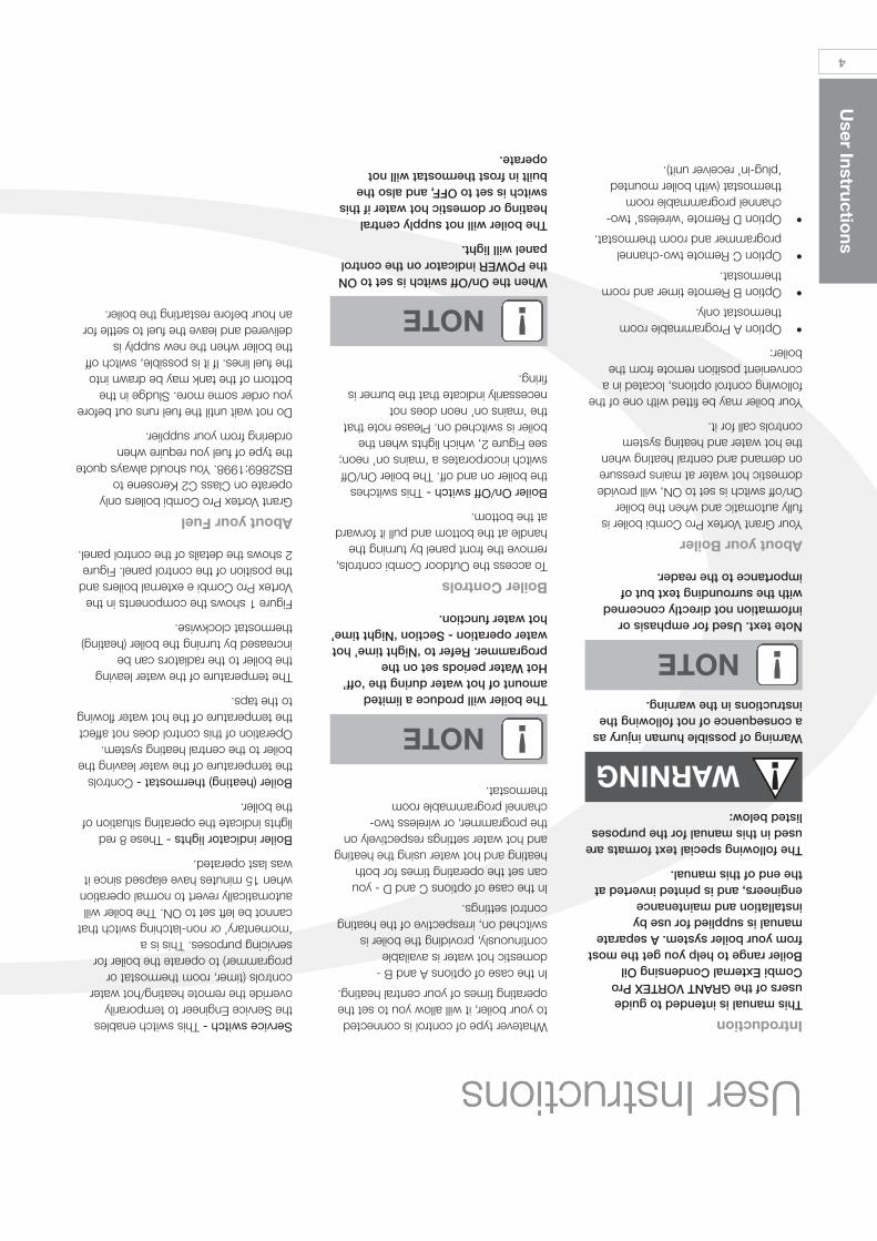
4
User Instructio
ns
User Instructions User InstructionsService switch -This switch enablesthe Service Engineer to temporarilyoverride the remote heating/hot watercontrols (timer, room thermostat orprogrammer) to operate the boiler forservicing purposes. This is a‘momentary’ or non-latching switch thatcannot be left set to ON. The boiler willautomatically revert to normal operationwhen 15 minutes have elapsed since itwas last operated.
Boiler indicator lights -These 8 redlights indicate the operating situation ofthe boiler.
Boiler (heating) thermostat -Controlsthe temperature of the water leaving theboiler to the central heating system.Operation of this control does not affectthe temperature of the hot water flowingto the taps.
The temperature of the water leavingthe boiler to the radiators can beincreased by turning the boiler (heating)thermostat clockwise.
Figure 1 shows the components in theVortex Pro Combi e external boilers andthe position of the control panel. Figure2 shows the details of the control panel.
About your FuelGrant Vortex Pro Combi boilers onlyoperate on Class C2 Kerosene toBS2869:1998. You should always quotethe type of fuel you require whenordering from your supplier.
Do not wait until the fuel runs out beforeyou order some more. Sludge in thebottom of the tank may be drawn intothe fuel lines. If it is possible, switch offthe boiler when the new supply isdelivered and leave the fuel to settle foran hour before restarting the boiler.
IntroductionThis manual is intended to guideusers of the GRANT VORTEX ProCombi External Condensing OilBoiler range to help you get the mostfrom your boiler system. A separatemanual is supplied for use byinstallation and maintenanceengineers, and is printed inverted atthe end of this manual.
The following special text formats areused in this manual for the purposeslisted below:
Warning of possible human injury asa consequence of not following theinstructions in the warning.
Note text. Used for emphasis orinformation not directly concernedwith the surrounding text but ofimportance to the reader.
About your BoilerYour Grant Vortex Pro Combi boiler isfully automatic and when the boilerOn/off switch is set to ON, will providedomestic hot water at mains pressureon demand and central heating whenthe hot water and heating systemcontrols call for it.
Your boiler may be fitted with one of thefollowing control options, located in aconvenient position remote from theboiler:
•Option A Programmable roomthermostat only.
•Option B Remote timer and roomthermostat.
•Option C Remote two-channelprogrammer and room thermostat.
•Option D Remote ‘wireless’ two-channel programmable roomthermostat (with boiler mounted‘plug-in’ receiver unit).
Whatever type of control is connectedto your boiler, it will allow you to set theoperating times of your central heating.
In the case of options A and B -domestic hot water is availablecontinuously, providing the boiler isswitched on, irrespective of the heatingcontrol settings.
In the case of options C and D - youcan set the operating times for bothheating and hot water using the heatingand hot water settings respectively onthe programmer, or wireless two-channel programmable roomthermostat.
!WARNING
!NOTEThe boiler will produce a limitedamount of hot water during the ‘off’Hot Water periods set on theprogrammer. Refer to ‘Night time’ hotwater operation - Section ‘Night time’hot water function.
Boiler ControlsTo access the Outdoor Combi controls,remove the front panel by turning thehandle at the bottom and pull it forwardat the bottom.
Boiler On/Off switch -This switchesthe boiler on and off. The boiler On/Offswitch incorporates a ‘mains on’ neon;see Figure 2, which lights when theboiler is switched on. Please note thatthe ‘mains on’ neon does notnecessarily indicate that the burner isfiring.
!NOTE
When the On/Off switch is set to ONthe POWER indicator on the controlpanel will light.
The boiler will not supply centralheating or domestic hot water if thisswitch is set to OFF, and also thebuilt in frost thermostat will notoperate.
!NOTE
Contents
Co
ntents
3
‘Night time’ Hot Water Function 6
Sealed Central Heating System 6
To Re-pressurise the Systemby adding Water 7
General Notes and Care ofyour System 7
Electricity Supply 7
Introduction 4
About your Boiler 4
Boiler Controls 4
About your Fuel 4
Lighting your Boiler 5
Turning off your Boiler 5
Points to Check if the BoilerFails to Light 6
Domestic Hot Water System 6
2
Service Lo
g
For use with Kerosene* only.After installing the boiler leave theseinstructions with the User.
This appliance is deemed a controlledservice and specific regional statutoryrequirements may be applicable.
*Operation on Bio-fuelAll Grant Vortex Pro condensing boilers,manufactured since May 2011, aresuitable for operation on both standardkerosene (Class C2 to BS2869) andalso bio-kerosene – up to a 30% blend(B30K).
All burner settings and nozzle sizes (asdetailed in Section 2.3 of this manual)are correct for both standard keroseneand bio-kerosene (B30K).
In order to operate this boiler on bio-kerosene it will be necessary to take the following actions:
a) Use a bio-kerosene (B30K)compatible flexible oil line in place of the oil line supplied with this boiler.
b) Have your oil storage tank and oilsupply line (including all pipework, sightgauges, filters, isolating valves, firevalves, de-aeration devices, etc.)checked for their compatibility with bio-kerosene (B30K).
Where necessary some, or all, of theseitems may have to be replaced with abio-kerosene compatible alternative.
c) Check the suitability of the fluesystem with Grant UK.
d) Use only bio-kerosene (B30K) thatconforms to OPS24.
IMPORTANTUnder no circumstances should theboiler be used with bio-kerosenewithout the above actions being takenfirst.
GRANT ENGINEERING (UK) LIMITEDHopton House, Hopton Industrial Estate, Devizes, Wiltshire SN10 2EUTel: 01380 736920 Fax: 01380 736991Email: [email protected] www.grantuk.com
This manual is accurate at the date of printing but will be superseded and should be disregarded if specifications and/orappearances are changed in the interests of continued product improvement.All good sold are subject to our official Conditions of Sale, a copy of which may be obtained on application.© Grant Engineering (UK) Limited 2012. No part of this manual may be reproduced by any means without prior written consent.
Service LogIt is recommended that the boiler shouldbe regularly serviced, at least once ayear, and the details entered in theBoiler Handbook by the serviceengineer.
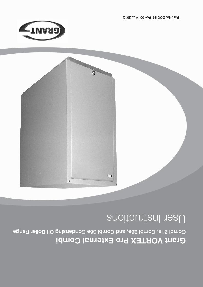
Grant VORTEX Pro External CombiCombi 21e, Combi 26e, and Combi 36e Condensing Oil Boiler Range
User Instructions
Part No. DOC 89 Rev 00. May 2012