Embed Size (px)
Citation preview

AB LIROS ELECTRONIC www.liros.se [email protected]
GRAIN-WATCH SYSTEM
InstallationsmanualGrain Watch Network SwitchGWNET11
InstallationsmanualGrain Watch Network SwitchGWNET11
C17
8A_I
nsta
llatio
nMan
ual_
EN G
WN
ET11
111
116.
cdr
1. General description 12. Before use 1
2.1. Important safety precautions 1
3. Safety certification and features 23.1. Certification label information 23.2. Safety approvals 2
4. Installation 44.1. Installation diagram 44.2. Components connected to the safe circuit 54.3. Wiring 64.4. Setup 74.5. Checklist before applying power 7
5. Maintenance and repair 75.1. Periodic maintenance 75.3. Repair 7
6. GWNET11 Specifications 86.1. Specifications 8
Table of contents
AB LIROS ELECTRONIC www.liros.se [email protected]
GWNET11 InstallationsmanualC
178A
_Ins
talla
tionM
anua
l_EN
GW
NET
11 1
1111
6.cd
r
GWNET11Grain Watch Network Switch1. General description
1AB LIROS ELECTRONIC www.liros.se [email protected]
2.1 Important safety precautions
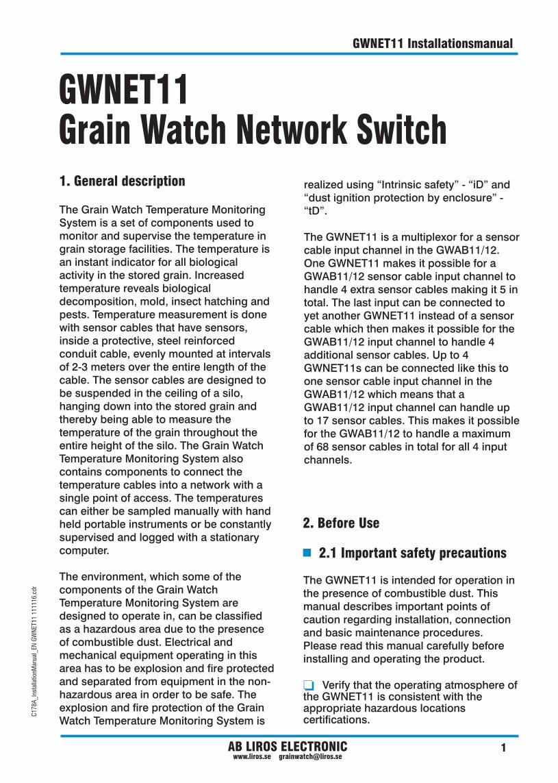
The GWNET11 is intended for operation in the presence of combustible dust. This manual describes important points of caution regarding installation, connection and basic maintenance procedures. Please read this manual carefully before installing and operating the product.
Verify that the operating atmosphere of the GWNET11 is consistent with the appropriate hazardous locations certifications.
o
2. Before Use
GWNET11 InstallationsmanualC
178A
_Ins
talla
tionM
anua
l_EN
GW
NET
11 1
1111
6.cd
r
The Grain Watch Temperature Monitoring System is a set of components used to monitor and supervise the temperature in grain storage facilities. The temperature is an instant indicator for all biological activity in the stored grain. Increased temperature reveals biological decomposition, mold, insect hatching and pests. Temperature measurement is done with sensor cables that have sensors, inside a protective, steel reinforced conduit cable, evenly mounted at intervals of 2-3 meters over the entire length of the cable. The sensor cables are designed to be suspended in the ceiling of a silo, hanging down into the stored grain and thereby being able to measure the temperature of the grain throughout the entire height of the silo. The Grain Watch Temperature Monitoring System also contains components to connect the temperature cables into a network with a single point of access. The temperatures can either be sampled manually with hand held portable instruments or be constantly supervised and logged with a stationary computer.
The environment, which some of the components of the Grain Watch Temperature Monitoring System are designed to operate in, can be classified as a hazardous area due to the presence of combustible dust. Electrical and mechanical equipment operating in this area has to be explosion and fire protected and separated from equipment in the non-hazardous area in order to be safe. The explosion and fire protection of the Grain Watch Temperature Monitoring System is
realized using “Intrinsic safety” - “iD” and “dust ignition protection by enclosure” - “tD”.
The GWNET11 is a multiplexor for a sensor cable input channel in the GWAB11/12. One GWNET11 makes it possible for a GWAB11/12 sensor cable input channel to handle 4 extra sensor cables making it 5 in total. The last input can be connected to yet another GWNET11 instead of a sensor cable which then makes it possible for the GWAB11/12 input channel to handle 4 additional sensor cables. Up to 4 GWNET11s can be connected like this to one sensor cable input channel in the GWAB11/12 which means that a GWAB11/12 input channel can handle up to 17 sensor cables. This makes it possible for the GWAB11/12 to handle a maximum of 68 sensor cables in total for all 4 input channels.
2 AB LIROS ELECTRONIC www.liros.se [email protected]
o
o
o
Verify that the environmental temperature is within the specifications of the GWNET11.
Make sure all local legislative requirements regarding electrical installation, authorization, Ex and possibly other requirements comply with the specifications of the Grain Watch Temperature Monitoring System.
Make sure only qualified personnel perform the installation.
3.1 Certification label information
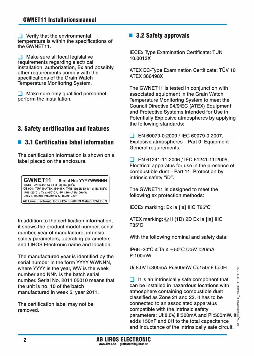
The certification information is shown on a label placed on the enclosure.
In addition to the certification information, it shows the product model number, serial number, year of manufacture, intrinsic safety parameters, operating parameters and LIROS Electronic name and location.
The manufactured year is identified by the serial number in the form YYYY WWNNN, where YYYY is the year, WW is the week number and NNN is the batch serial number. Serial No. 2011 05010 means that the unit is no. 10 of the batch manufactured in week 5, year 2011.
The certification label may not be removed.
3. Safety certification and features
3.2 Safety approvals
C17
8A_I
nsta
llatio
nMan
ual_
EN G
WN
ET11
111
116.
cdr
GWNET11 Installationsmanual
IECEx Type Examination Certificate: TUN 10.0013X
ATEX EC-Type Examination Certificate: TÜV 10 ATEX 386498X
The GWNET11 is tested in conjunction with associated equipment in the Grain Watch Temperature Monitoring System to meet the Council Directive 94/9/EC (ATEX) Equipment and Protective Systems Intended for Use in Potentially Explosive atmospheres by applying the following standards:
EN 60079-0:2009 / IEC 60079-0:2007, Explosive atmospheres – Part 0: Equipment – General requirements.
EN 61241-11:2006 / IEC 61241-11:2005, Electrical apparatus for use in the presence of combustible dust – Part 11: Protection by intrinsic safety “iD”.
The GWNET11 is designed to meet the following ex protection methods:
IECEx marking: Ex ia [ia] IIIC T85°C
ATEX marking: II (1D) 2D Ex ia [ia] IIIC T85°C
With the following nominal and safety data:
IP66 -20°C ≤ Ta ≤ +50°C U:5V I:20mA P:100mW
Ui:8.0V Ii:300mA Pi:500mW Ci:150nF Li:0H
It is an intrinsically safe component that can be installed in hazardous locations with atmosphere containing combustible dust classified as Zone 21 and 22. It has to be connected to an associated apparatus compatible with the intrinsic safety parameters: Ui:8.0V, Ii:300mA and Pi:500mW. It adds 150nF and 0H to the total capacitance and inductance of the intrinsically safe circuit.
o
o
o
GWNET11
AB Liros Electronic, Box 9124, S-200 39 Malmö, SWEDEN
IP66 U:5V I:20mA P:100mWU:8V I :300mA P :500mW C :150nF L :0H i i i i i
-20°C Ta +50°C £ £
Serial No: YYYYWWNNN0IECEx TUN 10.0013X Ex ia [ia] IIIC T85 C
0II (1D) 2D Ex ia [ia] IIIC T85 C 0044 TÜV 10 ATEX 386498X

3AB LIROS ELECTRONIC www.liros.se [email protected]
GWNET11 InstallationsmanualC
178A
_Ins
talla
tionM
anua
l_EN
GW
NET
11 1
1111
6.cd
r
o
o
o
o
o
o
It has an ingress protection of IP66. The ingress protection is not required by the intrinsic safety Ex protection method for the GWNET11.
The surface of the enclosure can reach a maximum temperature of 85°C when operated in an ambient temperature between -20°C to +50°C. This has not been determined with a dust layer test or dust immersion test.
Nominal values for U, I and P are 5V, 20mA and 100mW.
It has terminals for intrinsically safe circuits and components located in hazardous locations with atmosphere containing combustible dust classified as Zone 22, 21 and 20. The GWNET11 does not contain any limiting device or barrier and thus has no intrinsically safe output parameters. All terminals in the GWNET11 are part of the same intrinsically safe circuit, protected by a common associated apparatus, e.g. a GWAB11 or GWAB12.
The GWNET11 is also tested to meet the Council Directive 2004/108/EC Electromagnetic Compatibility (EMC) by applying the following standards:
EN/IEC 61000-6-2:2001, Electromagnetic Compatibility (EMC) – Part 6-2: Generic Standards – Immunity for Industrial Environments.
EN/IEC 61000-6-3:2001, Electromagnetic Compatibility (EMC) – Part 6-3: Generic Standards – Emission standard for residential, commercial and light-industrial environments.
4 AB LIROS ELECTRONIC www.liros.se [email protected]
4.1 Installation diagram
4. Installation
C17
8A_I
nsta
llatio
nMan
ual_
EN G
WN
ET11
111
116.
cdr
GWNET11 Installationsmanual
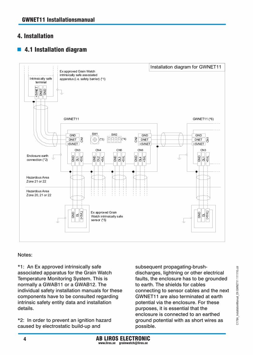
Installation diagram for GWNET11
Hazardous AreaZone 20, 21 or 22
Hazardous AreaZone 21 or 22
GWNET11 GWNET11 (*6)
GND
DNET
+5VNET
GND
DNET
+5VNET
GND
DNET
+5VNET
GN
D
DN
ET
+5V
NE
T
GN
D
GN
D
GN
D
GN
D
GN
D
DL1
DL2
DL3 DL1
DL4
+5V
L
+5V
L
+5V
L
+5V
L
+5V
L
CN
1
CN3
CN
2
CN4 CN5 CN6 CN3
CN
1
GN
D
GN
D
DL
DL
(+5V
L)
(+5
VL)Ex approved Grain
Watch intrinsically safe sensor (*5)
Ex approved Grain Watch intrinsically safe associated apparatus (i.e. safety barrier) (*1)
Enclosure earth connection (*2)
SW1 SW2
(*3) (*4)
Intrinsically safe terminal
Notes:
*1: An Ex approved intrinsically safe associated apparatus for the Grain Watch Temperature Monitoring System. This is normally a GWAB11 or a GWAB12. The individual safety installation manuals for these components have to be consulted regarding intrinsic safety entity data and installation details. *2: In order to prevent an ignition hazard caused by electrostatic build-up and
subsequent propagating-brush-discharges, lightning or other electrical faults, the enclosure has to be grounded to earth. The shields for cables connecting to sensor cables and the next GWNET11 are also terminated at earth potential via the enclosure. For these purposes, it is essential that the enclosure is connected to an earthed ground potential with as short wires as possible.
5AB LIROS ELECTRONIC www.liros.se [email protected]
GWNET11 InstallationsmanualC
178A
_Ins
talla
tionM
anua
l_EN
GW
NET
11 1
1111
6.cd
r
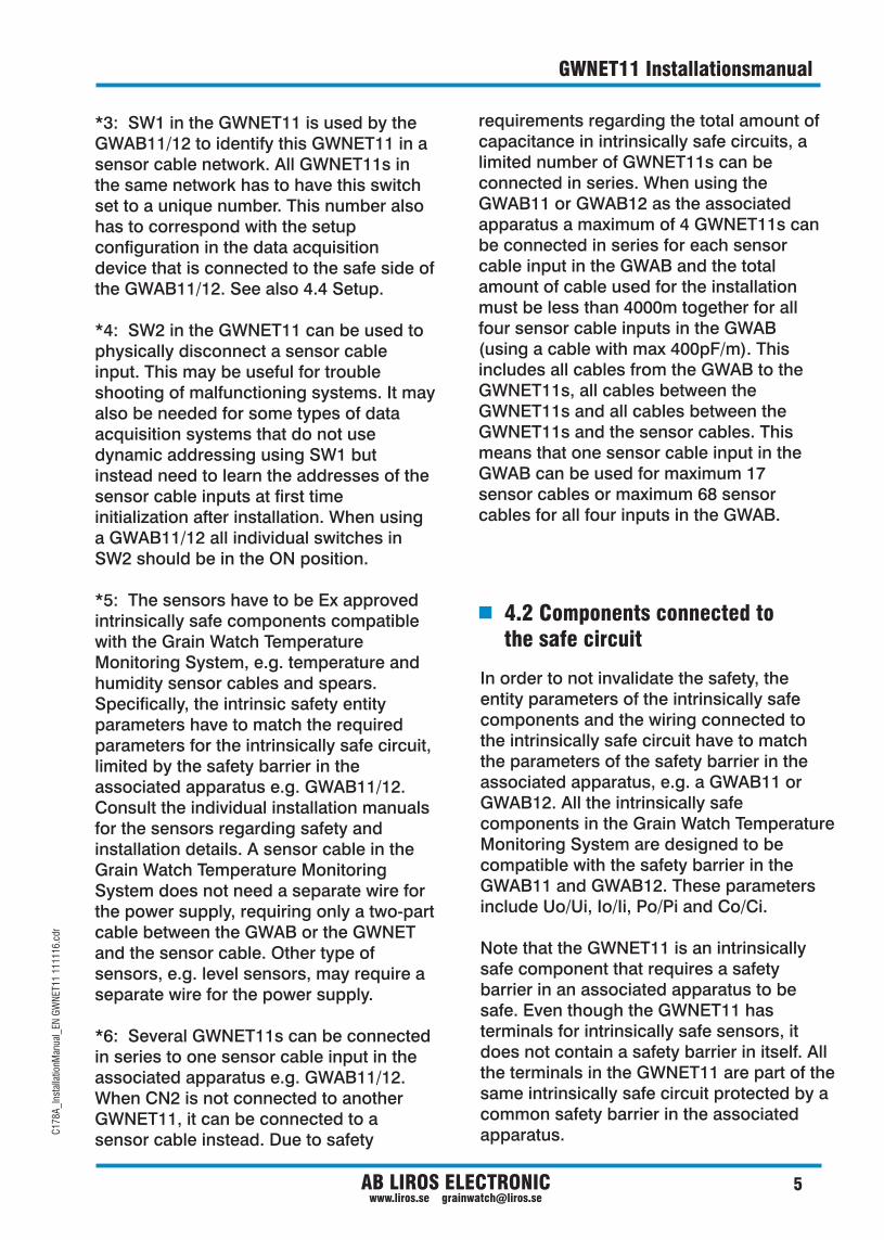
*3: SW1 in the GWNET11 is used by the GWAB11/12 to identify this GWNET11 in a sensor cable network. All GWNET11s in the same network has to have this switch set to a unique number. This number also has to correspond with the setup configuration in the data acquisition device that is connected to the safe side of the GWAB11/12. See also 4.4 Setup.
*4: SW2 in the GWNET11 can be used to physically disconnect a sensor cable input. This may be useful for trouble shooting of malfunctioning systems. It may also be needed for some types of data acquisition systems that do not use dynamic addressing using SW1 but instead need to learn the addresses of the sensor cable inputs at first time initialization after installation. When using a GWAB11/12 all individual switches in SW2 should be in the ON position.
*5: The sensors have to be Ex approved intrinsically safe components compatible with the Grain Watch Temperature Monitoring System, e.g. temperature and humidity sensor cables and spears. Specifically, the intrinsic safety entity parameters have to match the required parameters for the intrinsically safe circuit, limited by the safety barrier in the associated apparatus e.g. GWAB11/12. Consult the individual installation manuals for the sensors regarding safety and installation details. A sensor cable in the Grain Watch Temperature Monitoring System does not need a separate wire for the power supply, requiring only a two-part cable between the GWAB or the GWNET and the sensor cable. Other type of sensors, e.g. level sensors, may require a separate wire for the power supply.
*6: Several GWNET11s can be connected in series to one sensor cable input in the associated apparatus e.g. GWAB11/12. When CN2 is not connected to another GWNET11, it can be connected to a sensor cable instead. Due to safety
requirements regarding the total amount of capacitance in intrinsically safe circuits, a limited number of GWNET11s can be connected in series. When using the GWAB11 or GWAB12 as the associated apparatus a maximum of 4 GWNET11s can be connected in series for each sensor cable input in the GWAB and the total amount of cable used for the installation must be less than 4000m together for all four sensor cable inputs in the GWAB (using a cable with max 400pF/m). This includes all cables from the GWAB to the GWNET11s, all cables between the GWNET11s and all cables between the GWNET11s and the sensor cables. This means that one sensor cable input in the GWAB can be used for maximum 17 sensor cables or maximum 68 sensor cables for all four inputs in the GWAB.
4.2 Components connected to the safe circuit
In order to not invalidate the safety, the entity parameters of the intrinsically safe components and the wiring connected to the intrinsically safe circuit have to match the parameters of the safety barrier in the associated apparatus, e.g. a GWAB11 or GWAB12. All the intrinsically safe components in the Grain Watch Temperature Monitoring System are designed to be compatible with the safety barrier in the GWAB11 and GWAB12. These parameters include Uo/Ui, Io/Ii, Po/Pi and Co/Ci.
Note that the GWNET11 is an intrinsically safe component that requires a safety barrier in an associated apparatus to be safe. Even though the GWNET11 has terminals for intrinsically safe sensors, it does not contain a safety barrier in itself. All the terminals in the GWNET11 are part of the same intrinsically safe circuit protected by a common safety barrier in the associated apparatus.
6 AB LIROS ELECTRONIC www.liros.se [email protected]
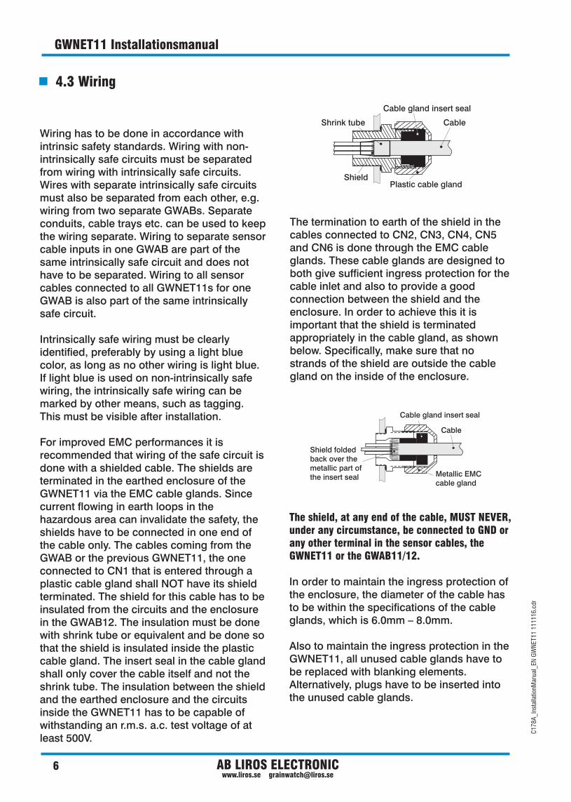
4.3 Wiring
Cable
Plastic cable gland
Cable gland insert seal
Shrink tube
Shield
Cable gland insert seal
Cable
Metallic EMC cable gland
Shield foldedback over the metallic part of the insert seal
The shield, at any end of the cable, MUST NEVER, under any circumstance, be connected to GND or any other terminal in the sensor cables, the GWNET11 or the GWAB11/12.
In order to maintain the ingress protection of the enclosure, the diameter of the cable has to be within the specifications of the cable glands, which is 6.0mm – 8.0mm.
Also to maintain the ingress protection in the GWNET11, all unused cable glands have to be replaced with blanking elements. Alternatively, plugs have to be inserted into the unused cable glands.
The termination to earth of the shield in the cables connected to CN2, CN3, CN4, CN5 and CN6 is done through the EMC cable glands. These cable glands are designed to both give sufficient ingress protection for the cable inlet and also to provide a good connection between the shield and the enclosure. In order to achieve this it is important that the shield is terminated appropriately in the cable gland, as shown below. Specifically, make sure that no strands of the shield are outside the cable gland on the inside of the enclosure.
C17
8A_I
nsta
llatio
nMan
ual_
EN G
WN
ET11
111
116.
cdr
GWNET11 Installationsmanual
Wiring has to be done in accordance with intrinsic safety standards. Wiring with non-intrinsically safe circuits must be separated from wiring with intrinsically safe circuits. Wires with separate intrinsically safe circuits must also be separated from each other, e.g. wiring from two separate GWABs. Separate conduits, cable trays etc. can be used to keep the wiring separate. Wiring to separate sensor cable inputs in one GWAB are part of the same intrinsically safe circuit and does not have to be separated. Wiring to all sensor cables connected to all GWNET11s for one GWAB is also part of the same intrinsically safe circuit.
Intrinsically safe wiring must be clearly identified, preferably by using a light blue color, as long as no other wiring is light blue. If light blue is used on non-intrinsically safe wiring, the intrinsically safe wiring can be marked by other means, such as tagging. This must be visible after installation.
For improved EMC performances it is recommended that wiring of the safe circuit is done with a shielded cable. The shields are terminated in the earthed enclosure of the GWNET11 via the EMC cable glands. Since current flowing in earth loops in the hazardous area can invalidate the safety, the shields have to be connected in one end of the cable only. The cables coming from the GWAB or the previous GWNET11, the one connected to CN1 that is entered through a plastic cable gland shall NOT have its shield terminated. The shield for this cable has to be insulated from the circuits and the enclosure in the GWAB12. The insulation must be done with shrink tube or equivalent and be done so that the shield is insulated inside the plastic cable gland. The insert seal in the cable gland shall only cover the cable itself and not the shrink tube. The insulation between the shield and the earthed enclosure and the circuits inside the GWNET11 has to be capable of withstanding an r.m.s. a.c. test voltage of at least 500V.

7AB LIROS ELECTRONIC www.liros.se [email protected]
4.4 Setup
GWNET11 InstallationsmanualC
178A
_Ins
talla
tionM
anua
l_EN
GW
NET
11 1
1111
6.cd
r
In order for the host system to be able to acquire the data from the sensor cables, each sensor cable has to be uniquely identified. The sensor cables are identified by an address as defined by the switch SW1 in the GWNET11 instead of using a unique ID attached to each sensor cable itself. This has the advantage that sensor cables can be swapped or replaced without reconfiguration of the host software. The address is then mapped to physical locations with a configuration setting in the host software.
SW1 is a 16 position rotary switch with positions numbered from 0-F. SW1 sets an address range with 4 addresses for all 4 sensor inputs in one GWNET11. To make the address for each sensor input unique, the input number, 1-4, is also used as an index in the address range for one GWNET11. The basic rule is that all GWNET11s connected to the same sensor cable network, e.g. one GWAB11 or GWAB12 should have SW1 set to a unique number.
When Liros TMS PC software is used, it is always accompanied with a CD that contains the software pre configured and with a binder containing schematic diagrams and component overviews with information about how the switches in the GWAB11/12s and GWNET11s should be set and at what input in the GWAB11/12s or the GWNET11s the sensor cables should be connected to. For a successful installation these instructions must always be followed exactly. If the sensor cables are not connected according to the instructions in the binder or the switches are not set according to the instructions, the software will not work and the temperatures for a sensor cable may not show up at all or it may be displayed as temperatures for another sensor cable.
5.1 Periodic maintenance
5. Maintenance and repair
The unit should periodically be cleaned from excessive layers of dust.
Check integrity of earth grounding and electrical connections at periodical intervals.
5.2 Repair
The GWNET11 unit is not field repairable and contains no replaceable parts. Any attempt to modify or repair this unit will void the warranty and the safety certification. If repair is necessary, return the unit to the manufacturer.
4.5 Checklist before applying power
Make sure to check that:
The GWNET11 is properly earthed.
Wiring is done according to the connection diagrams and intrinsic safety standards.
The shields for all cables in the hazardous locations are connected at one end only and that they are connected to the enclosure or sensor cable housing using the metal EMC cable glands.
All configuration switches in the system are set exactly as shown in the connection diagrams.
Unused cable glands are replaced with blanking elements or provided with adequate plugs.
o
o
o
o
o

6.1 Specifications
6. GWNET11 Specifications
U - Nominal voltage
I - Nominal current
P - Nominal power
Ingress protection
Maximum surface temperature
Operating temperature
Size
Certifications
Marking
U – Maximum voltage that can be applied to any terminal i
without invalidating safety I - Maximum current that can be applied to any terminal i
without invalidating safety P - Maximum power that can be applied to any terminal i
without invalidating safety C – Maximum unprotected internal capacitancei
5V
100mW
8.0V
300mA
500mW
150nF
IP66
85°C
-20°C – +50°C
L=125mm, B=80mm, H=57mm
IECEx: TUN 10.0013XATEX: TÜV 10 ATEX 386498XIECEx: Ex ia [ia] IIIC T85°CATEX: II (1D) Ex ia [ia] IIIC T85°C
20mA
8 AB LIROS ELECTRONIC www.liros.se [email protected]
C17
8A_I
nsta
llatio
nMan
ual_
EN G
WN
ET11
111
116.
cdr
GWNET11 Installationsmanual

AB Liros Electronic, Box 9124, S-200 39 Malmö, SWEDEN
Tel: +46 40 14 20 80, Fax: +46 40 94 73 88 www.liros.se, [email protected]
Silo Temperature MonitoringGRAIN-WATCHGRAIN-WATCH
®