Embed Size (px)
Citation preview
UNIVERSITY OF OSLODepartment of Informatics
GPU Virtualization
Master thesis
Kristoffer Robin
Stokke
May 1, 2012

Acknowledgements
I would like to thank my task provider, Johan Simon Seland, for the op-portunity to get dirty with bits, bytes, low level programming and virtualhardware.
I would also like to thank him, Stein Gjessing, Tore Østensen, Vera Her-mine Goebel, Rune V. Sjøen and Anders Asperheim for their help in review-ing my work and making suggestions along the way.
During the course of the thesis I have been involved in Qemu’s developercommunity. My sincerest thanks go to stefanha and pbrook on Qemu’s IRCchannel for pointing me in the way of Virtio, Qemu’s object model andQemu’s DMA facilities. Also a big thanks to the other developers who camewith tips, help and suggestions along the way!
To my fellow students at the ND lab; thank you all for a thriving envi-ronment with discussion and feedback.
Last but not least, my thanks go to family and friends who showed metheir support during the work.
i

ii
Abstract
In modern computing, the Graphical Processing Unit (GPU) has provenits worth beyond that of graphics rendering. Its usage is extended into thefield of general purpose computing, where applications exploit the GPU’smassive parallelism to accelerate their tasks. Meanwhile, Virtual Machines(VM) continue to provide utility and security by emulating entire computerhardware platforms in software. In the context of VMs, however, there is theproblem that their emulated hardware arsenal do not provide any modern,high end GPU. Thus any application running in a VM will not have accessto this computing resource, even if it can be backed by physically availableresources.
In this thesis we address this problem. We discuss different approaches toprovide VMs with GPU acceleration, and use this to design and implementVocale (pronounced ”Vocal”). Vocale is an extension to VM technology thatenables applications in a VM to accelerate their operation using a virtualGPU.
A critical look at our implementation is made to find out what makesthis task difficult, and what kind of demands such systems place on thesupporting software architecture. To do this we evaluate the efficiency of ourvirtual GPU contra a GPU running directly on physical hardware.
This thesis holds value for readers who are interested in virtualization andGPU technology. Vocale, however, also features a broad range of technolo-gies. Anyone with interest in programming in C / C++, software libraries,kernel modules, Python scripting and automatic code generation will have achance of finding something interesting here.
iii

iv
Contents
1 Introduction 11.1 Problem Statement . . . . . . . . . . . . . . . . . . . . . . . . 31.2 Overview . . . . . . . . . . . . . . . . . . . . . . . . . . . . . . 31.3 Vocale Software . . . . . . . . . . . . . . . . . . . . . . . . . . 4
2 Background 52.1 Terminology . . . . . . . . . . . . . . . . . . . . . . . . . . . . 62.2 Virtualization Technology . . . . . . . . . . . . . . . . . . . . 7
2.2.1 What is Virtualization? . . . . . . . . . . . . . . . . . 72.2.2 Types of Virtualization . . . . . . . . . . . . . . . . . . 92.2.3 Hypervisors . . . . . . . . . . . . . . . . . . . . . . . . 10
2.3 Graphical Processing Units . . . . . . . . . . . . . . . . . . . . 142.3.1 CUDA - a GPGPU Framework . . . . . . . . . . . . . 16
2.4 Linux Libraries and Kernel Modules . . . . . . . . . . . . . . . 242.4.1 Libraries . . . . . . . . . . . . . . . . . . . . . . . . . . 242.4.2 Kernel Modules . . . . . . . . . . . . . . . . . . . . . . 25
2.5 The Memory Management Unit . . . . . . . . . . . . . . . . . 262.5.1 Paging . . . . . . . . . . . . . . . . . . . . . . . . . . . 28
2.6 Previous Work . . . . . . . . . . . . . . . . . . . . . . . . . . 302.6.1 Virtual GPU Design Paradigms . . . . . . . . . . . . . 302.6.2 GViM . . . . . . . . . . . . . . . . . . . . . . . . . . . 312.6.3 New Research and Development . . . . . . . . . . . . . 33
3 Vocale - Design and Architecture 343.1 Design Goals . . . . . . . . . . . . . . . . . . . . . . . . . . . 353.2 Design Discussion . . . . . . . . . . . . . . . . . . . . . . . . . 35
3.2.1 Virtualization Boundary . . . . . . . . . . . . . . . . . 363.2.2 OS Platform and Library . . . . . . . . . . . . . . . . . 40
v
3.2.3 Hypervisor Platform . . . . . . . . . . . . . . . . . . . 433.3 Vocale - Architecture . . . . . . . . . . . . . . . . . . . . . . . 45
3.3.1 Virtual CUDA Library . . . . . . . . . . . . . . . . . . 473.3.2 Data Path . . . . . . . . . . . . . . . . . . . . . . . . . 493.3.3 CUDA Forwarder . . . . . . . . . . . . . . . . . . . . . 51
4 Vocale - Implementation 524.1 Qemu’s Object Model . . . . . . . . . . . . . . . . . . . . . . 534.2 Vocale 1.x . . . . . . . . . . . . . . . . . . . . . . . . . . . . . 55
4.2.1 Data Path . . . . . . . . . . . . . . . . . . . . . . . . . 564.2.2 Virtual CUDA Library . . . . . . . . . . . . . . . . . . 654.2.3 CUDA Forwarder . . . . . . . . . . . . . . . . . . . . . 74
4.3 Vocale 2.x . . . . . . . . . . . . . . . . . . . . . . . . . . . . . 754.3.1 Data Path Using Virtio-serial . . . . . . . . . . . . . . 784.3.2 Changes to the CUDA Forwarder . . . . . . . . . . . . 81
5 Discussion and Results 835.1 Evaluating Vocale . . . . . . . . . . . . . . . . . . . . . . . . . 84
5.1.1 Result Verification . . . . . . . . . . . . . . . . . . . . 845.1.2 Performance Metrics . . . . . . . . . . . . . . . . . . . 855.1.3 Performance Tests . . . . . . . . . . . . . . . . . . . . 86
5.2 Performance Evaluation . . . . . . . . . . . . . . . . . . . . . 895.2.1 Native Performance . . . . . . . . . . . . . . . . . . . . 895.2.2 Vocale 1.x . . . . . . . . . . . . . . . . . . . . . . . . . 955.2.3 Vocale 2.x . . . . . . . . . . . . . . . . . . . . . . . . . 101
5.3 Implementation Evaluation . . . . . . . . . . . . . . . . . . . . 1075.3.1 Vocale 1.x . . . . . . . . . . . . . . . . . . . . . . . . . 1085.3.2 Vocale 2.x . . . . . . . . . . . . . . . . . . . . . . . . . 114
6 Conclusion and Further Work 1166.1 Challenges of GPU Virtualization . . . . . . . . . . . . . . . . 116
6.1.1 Large Data Transfers . . . . . . . . . . . . . . . . . . . 1166.1.2 Library Virtualization . . . . . . . . . . . . . . . . . . 1176.1.3 Process Multiplexing . . . . . . . . . . . . . . . . . . . 1186.1.4 Architecture Independency . . . . . . . . . . . . . . . . 119
6.2 Future Work . . . . . . . . . . . . . . . . . . . . . . . . . . . . 1206.2.1 Zero Copy Data Transfers and Vocale 3.x . . . . . . . . 121
vi
A Test Equipment 129
B Virtio Performance 130
vii
List of Figures
1.1 A simple virtual machine running an operating system. . . . . 2
2.1 Terminology used throughout the thesis. . . . . . . . . . . . . 62.2 A virtualization scenario. . . . . . . . . . . . . . . . . . . . . . 82.3 The IBM S360 model 40 mainframe. Courtesy of the IBM
archives. . . . . . . . . . . . . . . . . . . . . . . . . . . . . . . 112.4 A type 1 hypervisor. . . . . . . . . . . . . . . . . . . . . . . . 122.5 A type 2 hypervisor. . . . . . . . . . . . . . . . . . . . . . . . 122.6 Vector addition as a parallel problem. . . . . . . . . . . . . . . 182.7 Illustrative figure of kernel threads executing on a GPU. . . . 212.8 The relationship between library references, so-names and real
names. . . . . . . . . . . . . . . . . . . . . . . . . . . . . . . . 252.9 Two processes running in separate, virtual address spaces. . . 272.10 Physical to virtual address mapping using the MMU. . . . . . 29
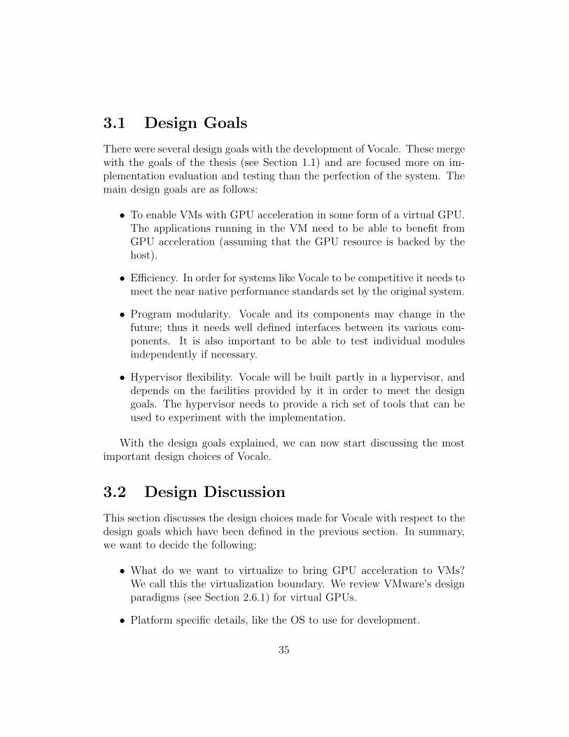
3.1 Shows how applications in a VM can be GPU accelerated usingfixed pass-through. . . . . . . . . . . . . . . . . . . . . . . . . 37
3.2 Shows how applications in a VM can be GPU accelerated usingmultiplexed pass-through. . . . . . . . . . . . . . . . . . . . . 38
3.3 Shows how applications in a VM can be GPU accelerated usingremote procedure calling. . . . . . . . . . . . . . . . . . . . . . 39
3.4 The general architecture of Vocale. . . . . . . . . . . . . . . . 463.5 Data transfer message structure. . . . . . . . . . . . . . . . . . 49
4.1 The source tree structure of Vocale. . . . . . . . . . . . . . . . 534.2 The implementation specific components of Vocale 1.x. . . . . 574.3 Call forwarding through Vocale’s subsystems. . . . . . . . . . 674.4 Wrapping of transfer data in message structures. . . . . . . . . 704.5 The implementation specific components of Vocale 2.x. . . . . 76
viii
5.1 Native call overhead. . . . . . . . . . . . . . . . . . . . . . . . 905.2 Native host to device bandwidth. . . . . . . . . . . . . . . . . 915.3 Native device to host bandwidth. . . . . . . . . . . . . . . . . 925.4 Native device to device bandwidth. . . . . . . . . . . . . . . . 925.5 Native DCT calculation time. . . . . . . . . . . . . . . . . . . 945.6 Native DCT calculation time (detailed). . . . . . . . . . . . . 945.7 Vocale 1.x call overhead. . . . . . . . . . . . . . . . . . . . . . 965.8 Vocale 1.x host to device bandwidth. . . . . . . . . . . . . . . 985.9 Vocale 1.x device to host bandwidth. . . . . . . . . . . . . . . 985.10 Vocale 1.x device to device bandwidth. . . . . . . . . . . . . . 995.11 Vocale 1.x DCT calculation time. . . . . . . . . . . . . . . . . 1005.12 Vocale 1.x DCT calculation time (detailed). . . . . . . . . . . 1015.13 Vocale 2.x call overhead. . . . . . . . . . . . . . . . . . . . . . 1025.14 Vocale 2.x host to device bandwidth. . . . . . . . . . . . . . . 1045.15 Vocale 2.x device to host bandwidth. . . . . . . . . . . . . . . 1045.16 Vocale 2.x device to device bandwidth. . . . . . . . . . . . . . 1055.17 Vocale 2.x DCT calculation time. . . . . . . . . . . . . . . . . 1065.18 Vocale 2.x DCT calculation time (detailed). . . . . . . . . . . 1075.19 Executing a function synchronously or asynchronously using
streams. . . . . . . . . . . . . . . . . . . . . . . . . . . . . . . 1085.20 Call forwarding through Vocale’s subsystems. . . . . . . . . . 1105.21 Race condition in Vocale. . . . . . . . . . . . . . . . . . . . . . 1105.22 A system running several CUDA applications, both in the host
and the guest. . . . . . . . . . . . . . . . . . . . . . . . . . . . 112
6.1 Valid and invalid combinations of host and guest CUDA libraries.1206.2 Zero copy data transfer from guest to host. . . . . . . . . . . . 122
B.1 Virtio bandwidth versus transfer size. Guest to Host. . . . . . 131B.2 Virtio bandwidth versus transfer size. Host to guest. . . . . . 131
ix
List of Tables
2.1 The main differences between GPUs and CPUs. . . . . . . . . 172.2 The main design paradigms behind front and back end GPU
virtualization. . . . . . . . . . . . . . . . . . . . . . . . . . . . 31
3.1 Overview of advantages and disadvantages of back end designparadigms. . . . . . . . . . . . . . . . . . . . . . . . . . . . . . 41
3.2 Overview of advantages and disadvantages of different frontend design paradigms. . . . . . . . . . . . . . . . . . . . . . . 42
4.1 The fat binary size field. . . . . . . . . . . . . . . . . . . . . . 73
5.1 Size of different call requests. . . . . . . . . . . . . . . . . . . 97
6.1 Architectural compatibility between Vocale’s guest and hostenvironments. . . . . . . . . . . . . . . . . . . . . . . . . . . . 121
x
Code Examples
2.1 Launching a kernel using the ECS. . . . . . . . . . . . . . . . 222.2 Launching a kernel using the execution control functions from
the CUDA runtime API. . . . . . . . . . . . . . . . . . . . . . 222.3 Launching a kernel using the execution control functions from
the CUDA driver API. . . . . . . . . . . . . . . . . . . . . . . 232.4 A simplified kernel to perform vector addition. . . . . . . . . . 233.1 A sample data structure for an API function’s input / output
parameters and call header. . . . . . . . . . . . . . . . . . . . 483.2 Interface provided by the transfer library to communicate with
the host. . . . . . . . . . . . . . . . . . . . . . . . . . . . . . . 503.3 A program initialization function called before main(..). . . . . 503.4 The host side interface of the data path. . . . . . . . . . . . . 514.1 Virtual device initialization from the command line. . . . . . . 544.2 Sample macro for registration of new class types. . . . . . . . 544.3 The data structure used to register information about new
object types. . . . . . . . . . . . . . . . . . . . . . . . . . . . . 554.4 I/O port interface provided by Qemu. . . . . . . . . . . . . . . 594.5 Above: The message handler function type. Below: A func-
tion to register handlers to a port. . . . . . . . . . . . . . . . . 594.6 ls output listing for a VM running Vocale 1.x. . . . . . . . . . 604.7 A simplified example of the cudamodule write handler. . . . . 614.8 A simplified example of the cudamodule read handler. . . . . . 624.9 Transfer library implementation. . . . . . . . . . . . . . . . . . 634.10 A snippet of the nvcc.profile file. . . . . . . . . . . . . . . . 664.11 An example fake implementation of a CUDA API call. . . . . 694.12 The most basic API function for device memory transfers. . . 694.13 Simplified message handler implementation. . . . . . . . . . . 75
xi
4.14 Function forwarding for the cudaGetDeviceProperties(..) func-tion. . . . . . . . . . . . . . . . . . . . . . . . . . . . . . . . . 77
4.15 An example invocation of the datatransfer-serial device. . 784.16 Datatransfer-serial device registration. . . . . . . . . . . . 784.17 The datatransfer-serial device constructor. . . . . . . . . . 794.18 The datatransfer-serial received data routine. . . . . . . . 804.19 The datatransfer-serial message callback function. . . . . 825.1 Example solution to Vocale’s race condition. . . . . . . . . . . 1116.1 Vocale’s call header extended with the process and thread ID
of the calling guest application. . . . . . . . . . . . . . . . . . 119
xii
Chapter 1
Introduction
Virtualization is an abstract concept with roots deep into IBM’s mainframehistory. In computing, virtualization technology attempts to create a virtual,as in ”fake”, version of a system, that reacts and behaves like the real one[34].These systems can provide many benefits in form of security, utility andcompatibility.
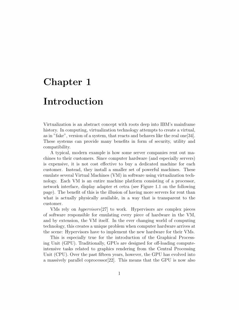
A typical, modern example is how some server companies rent out ma-chines to their customers. Since computer hardware (and especially servers)is expensive, it is not cost effective to buy a dedicated machine for eachcustomer. Instead, they install a smaller set of powerful machines. Theseemulate several Virtual Machines (VM) in software using virtualization tech-nology. Each VM is an entire machine platform consisting of a processor,network interface, display adapter et cetra (see Figure 1.1 on the followingpage). The benefit of this is the illusion of having more servers for rent thanwhat is actually physically available, in a way that is transparent to thecustomer.
VMs rely on hypervisors [27] to work. Hypervisors are complex piecesof software responsible for emulating every piece of hardware in the VM,and by extension, the VM itself. In the ever changing world of computingtechnology, this creates a unique problem when computer hardware arrives atthe scene: Hypervisors have to implement the new hardware for their VMs.
This is especially true for the introduction of the Graphical Process-ing Unit (GPU). Traditionally, GPUs are designed for off-loading compute-intensive tasks related to graphics rendering from the Central ProcessingUnit (CPU). Over the past fifteen years, however, the GPU has evolved intoa massively parallel coprocessor[22]. This means that the GPU is now also
1
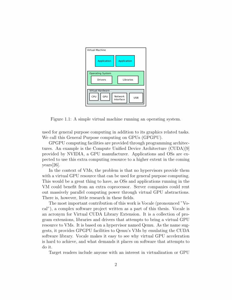
Figure 1.1: A simple virtual machine running an operating system.
used for general purpose computing in addition to its graphics related tasks.We call this General Purpose computing on GPUs (GPGPU).
GPGPU computing facilities are provided through programming architec-tures. An example is the Compute Unified Device Architecture (CUDA)[9]provided by NVIDIA, a GPU manufacturer. Applications and OSs are ex-pected to use this extra computing resource to a higher extent in the comingyears[26].
In the context of VMs, the problem is that no hypervisors provide themwith a virtual GPU resource that can be used for general purpose computing.This would be a great thing to have, as OSs and applications running in theVM could benefit from an extra coprocessor. Server companies could rentout massively parallel computing power through virtual GPU abstractions.There is, however, little research in these fields.
The most important contribution of this work is Vocale (pronounced ”Vo-cal”), a complex software project written as a part of this thesis. Vocale isan acronym for Virtual CUDA Library Extension. It is a collection of pro-gram extensions, libraries and drivers that attempts to bring a virtual GPUresource to VMs. It is based on a hypervisor named Qemu. As the name sug-gests, it provides GPGPU facilities to Qemu’s VMs by emulating the CUDAsoftware library. Vocale makes it easy to see why virtual GPU accelerationis hard to achieve, and what demands it places on software that attempts todo it.
Target readers include anyone with an interest in virtualization or GPU
2
technology. Others may be interested in the technical areas and challengesof Vocale, including application / OS programming, the CUDA framework,the Qemu hypervisor, Python scripting and automatic code generation.
1.1 Problem Statement
Today’s hypervisors incorporate no GPU acceleration for their VMs. Thispresents an issue in cases where the physically available GPU resources in amachine cannot be utilized by the applications running in a VM. This thesiswants to:
• Look at previous work in the field of GPU virtualization.
• Look at possible design paradigms for and implement a virtual GPUsuitable for general purpose computation in a hypervisor.
– Identify the challenges and trade-offs of implementing this intoexisting virtualization technology.
– If possible, devise new methods or proposals to overcome the chal-lenges.
– Study the performance impact of virtualized GPU accelerationagainst its non-virtualized counterpart.
1.2 Overview
The disposition of the thesis is as follows. This chapter describes the moti-vation and problem statement for this work.
The following chapter presents background information about virtualiza-tion technology, GPUs, kernel modules, software libraries and virtual mem-ory. We also present a short terminology for terms used throughout thethesis. This is important to understand Vocale and the results and conclu-sions presented later. Finally, we have a look at previous work in the field ofGPU virtualization, as well as the research and development that occurredduring the work of the thesis.
The third and fourth chapters outline the design and implementation ofVocale. Vocale is an extension to the Qemu hypervisor that provides VMswith GPU acceleration, and was developed as a part of this thesis. We
3

discuss the design and general architecture of Vocale in the design chapter,and go into implementation specific details in the implementation chapter.This shows how Vocale accomplishes its tasks. Note that Vocale has beenbuilt in two iterations, 1.x and 2.x.
Chapter five discusses benchmark and test results of Vocale as well as theimplementation itself. We argument for and describe the performance testsVocale has been subjected to, and compare the performance of Vocale withits non-virtualized counterpart.
The final chapter presents the conclusions that have been derived from thework, and discusses opportunities for further work in this area. We state themain problems involved in the design and implementation of virtual GPUsand the demands it places on the hypervisor.
Appendix A and B contains, respectively, hardware details about ourtest bed and a small performance test of virtio-serial, a virtual hardwaredevice used by Vocale. We will reference these when necessary.
1.3 Vocale Software
Vocale’s source code can be downloaded from SourceForge at the followinglink location:
https://sourceforge.net/projects/vcuda/
At the back of the thesis you will also find a DVD with the softwareproject. Refer to the readme.pdf file in the root folder for instructions oninstallation and usage. The file also contains detailed instructions on howcode can be added to Qemu, and other information that has no place in thisthesis (but is useful for developers).
4

Chapter 2
Background
This chapter gives background information about important concepts andtechnologies necessary to understand Vocale and the work presented in thisthesis.
The chapter layout is as follows. The first section yields a short butimportant terminology that is used throughout the thesis.
The following section gives a thorough introduction to virtualization, ex-plaining what it is, the advantages it provides and its variations in a historicalcontext. It then explains hypervisors and VMs in detail.
The third section gives an introduction to GPUs and NVIDIA’s CUDAframework, a GPGPU programming architecture. We outline the architec-tural differences between GPUs and CPUs as we describe how GPGPU tech-nology can accelerate program operation. A short introduction to CUDA’sAPI and programming model is given to prepare the reader for the designand implementation of Vocale’s virtual CUDA library.
The fourth section gives a brief look at Linux software libraries and ker-nel modules. Vocale makes extensive use of these to achieve its goals, andespecially kernel module programming represents a large amount of the workin this thesis.
The fifth section gives a brief look at the Memory Management Unit(MMU) of CPUs. As we will see in our results chapter, finding an efficientway to transfer large amounts of data between a VM and its hypervisor ishard. Understanding the MMU is key to understand why this is and ourconcluding remarks in the final chapter. It is also required for any futurework to understand the MMU and appreciate the complexity it imposes onVocale.
5
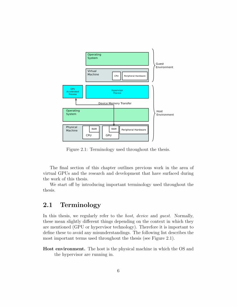
Figure 2.1: Terminology used throughout the thesis.
The final section of this chapter outlines previous work in the area ofvirtual GPUs and the research and development that have surfaced duringthe work of this thesis.
We start off by introducing important terminology used throughout thethesis.
2.1 Terminology
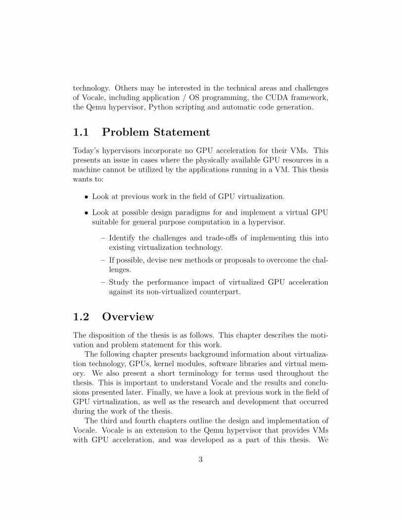
In this thesis, we regularly refer to the host, device and guest. Normally,these mean slightly different things depending on the context in which theyare mentioned (GPU or hypervisor technology). Therefore it is important todefine these to avoid any misunderstandings. The following list describes themost important terms used throughout the thesis (see Figure 2.1).
Host environment. The host is the physical machine in which the OS andthe hypervisor are running in.
6
Guest environment. The guest is the VM as emulated by the hypervisor,and its OS.
Device. Denotes the physical GPU of the host.
Device memory transfers. GPUs have their own, dedicated memory. GPUaccelerated applications constantly transfer data between the host andGPU memory areas. Device memory transfers encompass data trans-fers in all directions, which can be:
• Host to Device (H2D).
• Device to Host (D2H).
• Device to Device (D2D).
Note that in some cases, the host will be replaced with the guest whenspeaking about device memory transfers. This is natural when referring todata that is passed between the guest environment and the device.
With the terminology explained, we can start with background informa-tion. The next section introduces virtualization technology.
2.2 Virtualization Technology
This section gives a more detailed explanation of what virtualization is, beforegiving a brief look at it from a historical perspective. At the end of the sectionwe look at different hypervisors, which is important for our design discussionin Chapter 3.
2.2.1 What is Virtualization?
In short, virtualization is to impose the role of another system. This processis called emulation. Virtualization technology creates an unreal, fake versionof a system in a way that is transparent to the users of that system. Trans-parency is achieved by preserving the system’s interface. The real benefit ofthis is to be able to perform the internal tasks of the system in new ways; aswe will see now in the following example.
Consider an application that depends on a FAT File System (FS) to work.Such an application can be seen to the left in Figure 2.2 on the following page.Then, imagine what would happen if you had to upgrade your hard drive and
7

Figure 2.2: A virtualization scenario.
end up with another FS, for example NTFS. The application would now stopworking. A solution to this problem could be to virtualize the FAT FS; seethe right model in Figure 2.2. In the figure, the virtual system synthesizesFAT operations into NTFS operations in a way that preserves the old FATinterface. Thus the application can still work, and the trade-off is some extraoverhead in FS operations.
Virtualization is not a new concept. Its first traces can be found in the oldmainframe computers of IBM, used for providing backwards compatibility[19],virtual memory[18] and Virtual Machine Monitors[13] (covered in Section2.2.3). These systems were among the first to provide hardware assistedprogramming and multiprogramming, which is taken for granted by today’sprogrammers.
Virtualization is still an active technology today because of the advantagesit provides; utility, compatibility and security. Java applications run on aVM, achieving compatibility as the VM is compatible with different computerarchitectures. The server company example from the introduction is bothcost-effective and secure. Developers use VMs to test applications designedfor other CPU architectures than the one they are physically using, achievingutility. Virtual memory creates the illusion of having more main memory(RAM) than what is physically available. Harmful programs can be run ina virtual environment without endangering the entire system, a techniquecalled sand-boxing. Finally, virtualization can be used to create abstractionsthat allow for sharing of hardware resources, which is important in cloudcomputing[31].
However, most of these virtualization examples are out of scope for this
8
document, which focuses on hypervisors.
2.2.2 Types of Virtualization
The field of virtualization brings about some general concepts that describesthe properties of a virtual system.
Full Virtualization. In full virtualization systems, the user of the systemhas absolutely no idea that it is running in an emulated environment.It acts and interacts with the environment in a way that is identical torunning in a real system. These systems, and especially hypervisors,traditionally suffer from poor performance.
Paravirtualization denotes virtualization scenarios where the user knowsthat it is running in an emulated environment, as opposed to full virtu-alization. This can have a positive impact on performance of the systemin cases where full virtualization imposes a large emulation overhead.
Hardware Assisted Virtualization refers to the usage of hardware to ac-celerate or help the operation of virtual systems. For example, Popekand Goldberg[23] state that for a processor architecture to be virtual-izable, all privileged machine instructions must cause traps on failure,which is a form of exception handler. The x86 processor architectureis hard to virtualize because some privileged instructions fail withoutcausing traps. The problem of this is that the hypervisor is never no-tified that its guest attempted to execute the instruction, and hence isunable to emulate it in software. To address this, Intel has developedhardware support called Intel-VT[28] to address this and four otherissues. While investigation of these technologies is out of scope for thisthesis, they significantly accelerate the operation of VMs.
Hardware and Software Virtualization describes the type of the sys-tem being emulated. Qemu emulates a VM (hardware virtualization),while a program called Wine emulates a Windows compatibility layeron top of Linux (software virtualization). A virtual library like theone implemented by Wine is advantageous over the alternative whenconsidering performance, which is to install Windows in a VM.
9
2.2.3 Hypervisors
Hypervisors are highly complex programs that emulate entire computer hard-ware platforms, called VMs, in software. The VM incorporates an emulatedCPU, hard drive, physical memory, network interface, display adapter (GPU)et cetra. The VM can be used just like a physical machine.
The grandfather of modern hypervisors can be found in the CP/CMS re-search project[13] from the mid 1960s. It is interesting to have a quick lookat this system not only because it relied on virtual systems such as virtualmemory and virtual disks, but also provided a virtual system in itself. Itconsisted of an S/360 model 40 mainframe (see Figure 2.3 on the follow-ing page) featuring a Control Program (CP) and a Conversational MonitorSystem (CMS).
The CP was called a Virtual Machine Monitor, but is most similar totoday’s hypervisors in that it could emulate VMs in software. Combinedwith CMS, a form of single user interactive OS, it gave users simultaneousaccess to a machine, and was one of the first systems to be able to do this.This old project provided increased utility and security by letting each userwork in an isolated environment, unable to affect and harm others.
Hypervisor Design Strategies
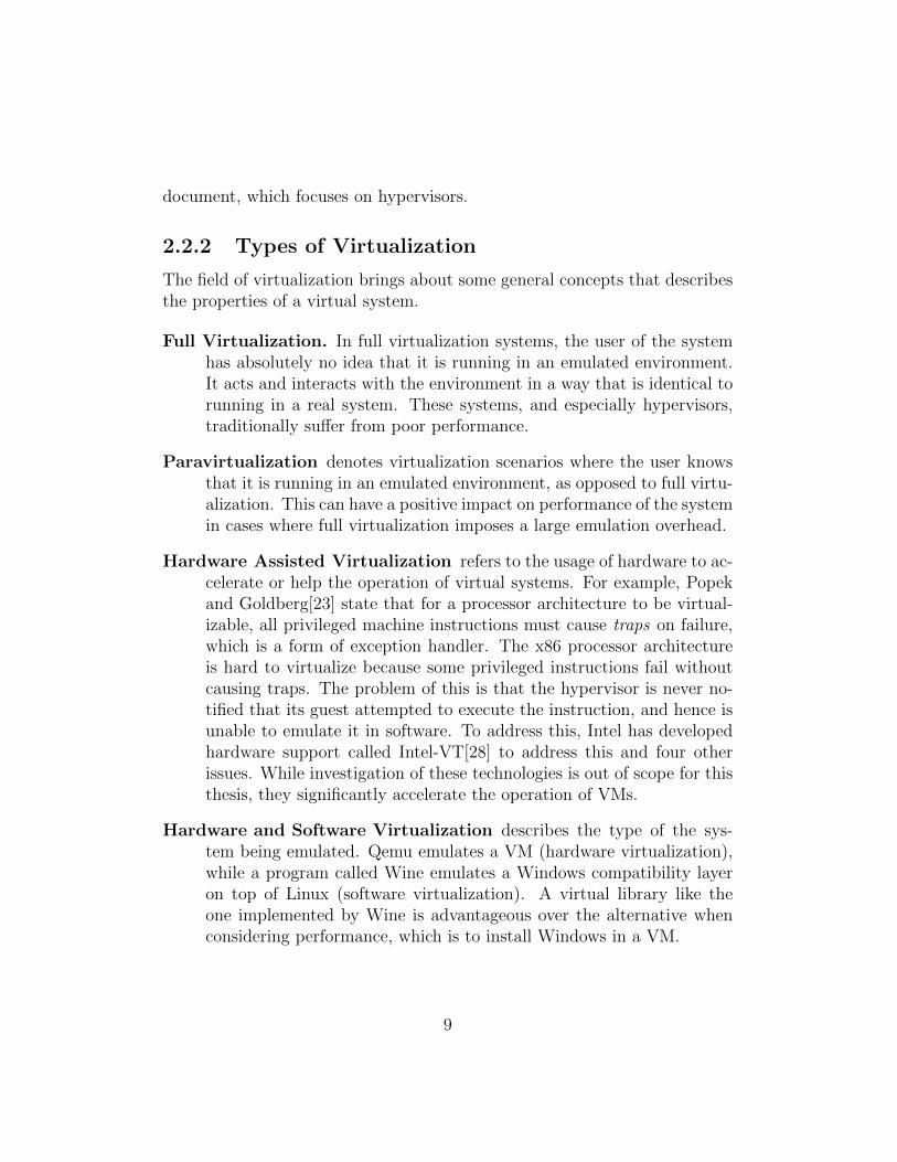
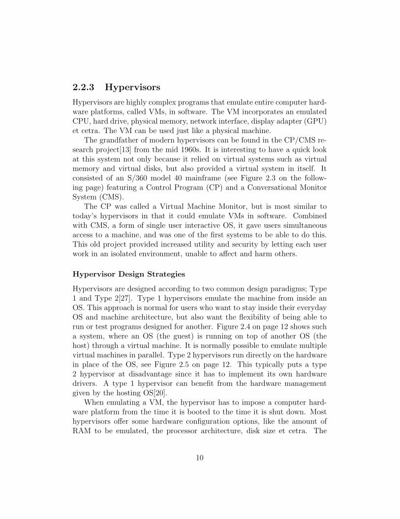
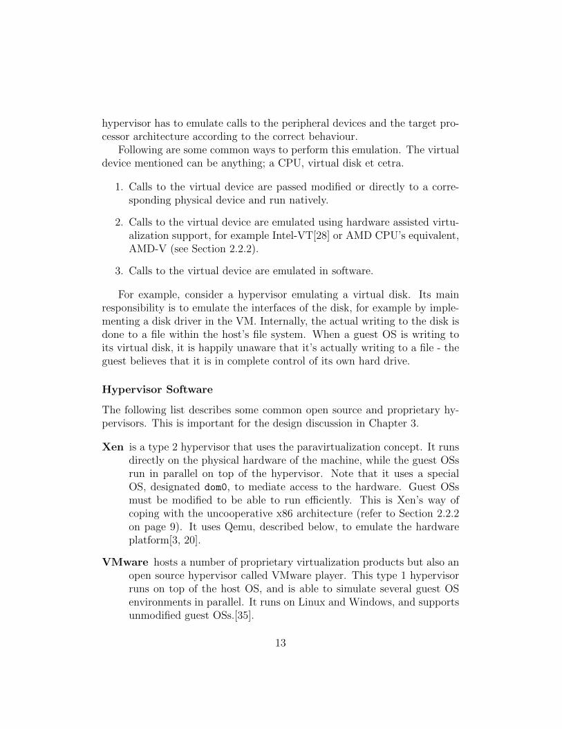
Hypervisors are designed according to two common design paradigms; Type1 and Type 2[27]. Type 1 hypervisors emulate the machine from inside anOS. This approach is normal for users who want to stay inside their everydayOS and machine architecture, but also want the flexibility of being able torun or test programs designed for another. Figure 2.4 on page 12 shows sucha system, where an OS (the guest) is running on top of another OS (thehost) through a virtual machine. It is normally possible to emulate multiplevirtual machines in parallel. Type 2 hypervisors run directly on the hardwarein place of the OS, see Figure 2.5 on page 12. This typically puts a type2 hypervisor at disadvantage since it has to implement its own hardwaredrivers. A type 1 hypervisor can benefit from the hardware managementgiven by the hosting OS[20].
When emulating a VM, the hypervisor has to impose a computer hard-ware platform from the time it is booted to the time it is shut down. Mosthypervisors offer some hardware configuration options, like the amount ofRAM to be emulated, the processor architecture, disk size et cetra. The
10

Figure 2.3: The IBM S360 model 40 mainframe. Courtesy of the IBMarchives.
11
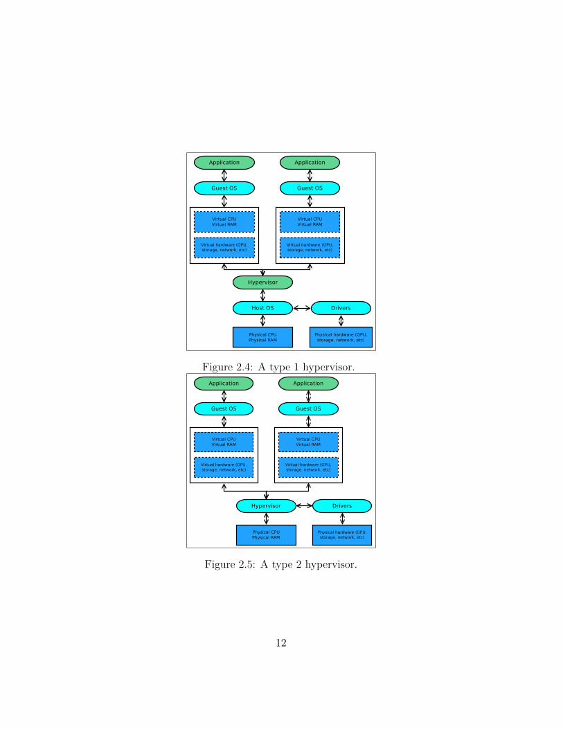
Figure 2.4: A type 1 hypervisor.
Figure 2.5: A type 2 hypervisor.
12
hypervisor has to emulate calls to the peripheral devices and the target pro-cessor architecture according to the correct behaviour.
Following are some common ways to perform this emulation. The virtualdevice mentioned can be anything; a CPU, virtual disk et cetra.
1. Calls to the virtual device are passed modified or directly to a corre-sponding physical device and run natively.
2. Calls to the virtual device are emulated using hardware assisted virtu-alization support, for example Intel-VT[28] or AMD CPU’s equivalent,AMD-V (see Section 2.2.2).
3. Calls to the virtual device are emulated in software.
For example, consider a hypervisor emulating a virtual disk. Its mainresponsibility is to emulate the interfaces of the disk, for example by imple-menting a disk driver in the VM. Internally, the actual writing to the disk isdone to a file within the host’s file system. When a guest OS is writing toits virtual disk, it is happily unaware that it’s actually writing to a file - theguest believes that it is in complete control of its own hard drive.
Hypervisor Software
The following list describes some common open source and proprietary hy-pervisors. This is important for the design discussion in Chapter 3.
Xen is a type 2 hypervisor that uses the paravirtualization concept. It runsdirectly on the physical hardware of the machine, while the guest OSsrun in parallel on top of the hypervisor. Note that it uses a specialOS, designated dom0, to mediate access to the hardware. Guest OSsmust be modified to be able to run efficiently. This is Xen’s way ofcoping with the uncooperative x86 architecture (refer to Section 2.2.2on page 9). It uses Qemu, described below, to emulate the hardwareplatform[3, 20].
VMware hosts a number of proprietary virtualization products but also anopen source hypervisor called VMware player. This type 1 hypervisorruns on top of the host OS, and is able to simulate several guest OSenvironments in parallel. It runs on Linux and Windows, and supportsunmodified guest OSs.[35].
13
VirtualBox is also a type 1 hypervisor. It supports hardware virtualiza-tion and uses Qemu to emulate the hardware platform. One of the ad-vantages of VirtualBox is its independency of hardware virtualizationsupport, making it a viable alternative for older computer hardware aswell as new. It is also well documented and supports Linux as the hostand guest OS[11].
Qemu is a type 1 hypervisor using the Linux kernel to accelerate perfor-mance. It makes use of hardware assisted virtualization and a specialkernel module called KVM (Kernel-based Virtual Machines). This givesQemu impressive performance. Qemu is also used by other hypervisors,such as Xen, to emulate a hardware platform. [32, 33, 20].
With our introduction of virtualization technology, we can now proceedwith the next section which describes GPU technology.
2.3 Graphical Processing Units
This section introduces the GPU. We outline the parallel nature of the GPUin a historical view, and show how the GPU has become a general purposecoprocessor. The following subsection explains CUDA, where we presentCUDA’s programming model, its main architectural concepts and its APIs.It is important to understand how developers interact with CUDA to realisewhat Vocale needs to do to emulate it.
Modern GPUs are massively parallel devices dedicated to generating anddrawing graphical objects on a screen. It sees its daily use as a coprocessorto the CPU by offloading graphics related processing. GPUs are necessaryin scenarios where the CPU cannot be expected to satisfy all the compu-tational demands related to graphical rendering, networking, program flow,interrupts et cetra. Examples include gaming scenarios and live video encod-ing / decoding.
The need for a dedicated graphics device is marked by the introductionof a certain piece of software called Sketchpad. Sketchpad was a computerprogram that introduced many of the modern Graphical User Interface (GUI)concepts used today. It was developed by a PhD student at MIT named IvanSutherland as part of his PhD research in 1963, and provided an interfaceto draw, copy, move and describe objects on a screen. It is considered thedawn of graphical computing and had huge effect on this research area in
14
later years. In 1968, Ivan Sutherland and David Evans founded Evans &Sutherland, a pioneer company creating graphics hardware for the computersystems at MIT.
Up until then, graphics devices were purely vector based in that theyaccessed vector endpoints and drew the corresponding lines on a monitor.This changed with the introduction of raster graphics, where each pixel inthe display device is represented by an amount of bits in memory. JimClark, who had worked at Evans & Sutherland, co-founded another graphicshardware company in 1981 called Silicon Graphics (SGI). SGI is famous forJim Clark’s Geometry Engine, which did many of the operations requiredto display an image on a screen. This was an important development incomputer graphics hardware, as the graphics requirements of software wassteadily increasing, and the main processor could not be expected to do allthe graphics-related work by itself. The Geometry Engine solved this byoff-loading the graphics related tasks from the main processor[4].
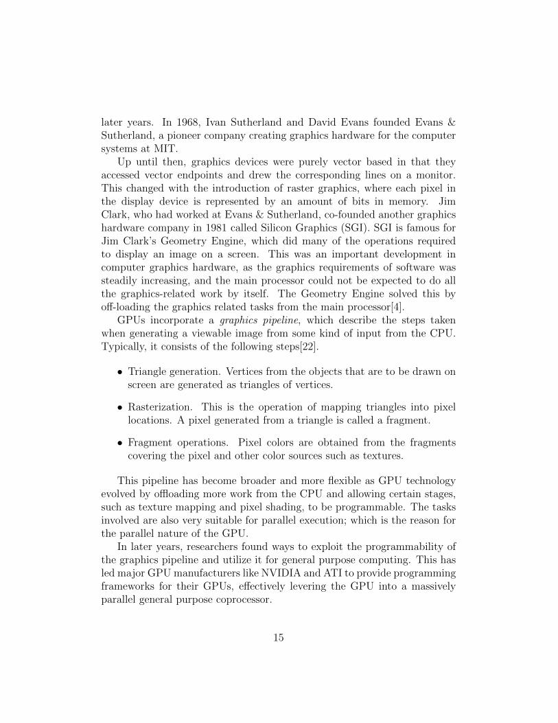
GPUs incorporate a graphics pipeline, which describe the steps takenwhen generating a viewable image from some kind of input from the CPU.Typically, it consists of the following steps[22].
• Triangle generation. Vertices from the objects that are to be drawn onscreen are generated as triangles of vertices.
• Rasterization. This is the operation of mapping triangles into pixellocations. A pixel generated from a triangle is called a fragment.
• Fragment operations. Pixel colors are obtained from the fragmentscovering the pixel and other color sources such as textures.
This pipeline has become broader and more flexible as GPU technologyevolved by offloading more work from the CPU and allowing certain stages,such as texture mapping and pixel shading, to be programmable. The tasksinvolved are also very suitable for parallel execution; which is the reason forthe parallel nature of the GPU.
In later years, researchers found ways to exploit the programmability ofthe graphics pipeline and utilize it for general purpose computing. This hasled major GPU manufacturers like NVIDIA and ATI to provide programmingframeworks for their GPUs, effectively levering the GPU into a massivelyparallel general purpose coprocessor.
15

Examples of such programming framework are NVIDIA’s CUDA frame-work, and the Khronous Group’s Open Computing Language. In the follow-ing subsection, we describe CUDA’s programming model and API. This isto prepare the reader for the design and implementation of Vocale.
2.3.1 CUDA - a GPGPU Framework
CUDA is a general purpose programming architecture for NVIDIA’s GPUs.When applied correctly, it can be used to offload tasks from a CPU to de-crease the runtime of a task, which is often the objective of optimization.
To understand CUDA it is important to understand the difference be-tween CPUs and NVIDIA’s GPUs. From a hardware perspective, the heartof the GPU consists of special purpose microprocessors call Streaming Mul-tiprocessors (SM). GPUs incorporate a varying number of SMs; it can beanything from 10 to 1500 SMs depending on the product.
SMs have a much smaller instruction set than CPUs, but can run up toeight threads in parallel as long as they follow the same execution path. Thatmeans more than 10000 threads running simultaneously for high end GPUs.Each thread runs the same program but with different data. This archi-tecture is called Single Instruction, Multiple Thread (SIMT) as opposed toSingle Instruction, Multiple Data (SIMD) found in the MMX/SSE facilitiesof normal Intel CPUs. SMs are also called CUDA Cores.
Table 2.1 on the following page shows the main differences between GPUsand CPUs.
The GPU does not have any protection mechanism such as virtual mem-ory or instruction privilege rings. It is also worth noting that GPU processingfollows strict performance rules in order to achieve all the benefits of the GPUlisted in Table 2.1 on the next page [10].
• All eight threads running on an SM must be non-divergent, that is,follow the same program execution path.
• Memory throughput is high only when memory coalescing is achieved,that is, special memory access patterns must be followed.
• Instruction throughput is high only when certain register register de-pendencies are met.
16
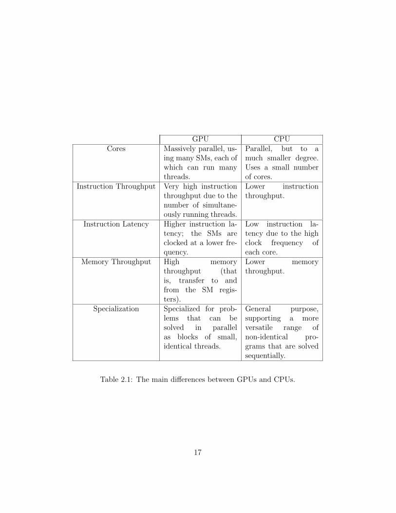
GPU CPUCores Massively parallel, us-
ing many SMs, each ofwhich can run manythreads.
Parallel, but to amuch smaller degree.Uses a small numberof cores.
Instruction Throughput Very high instructionthroughput due to thenumber of simultane-ously running threads.
Lower instructionthroughput.
Instruction Latency Higher instruction la-tency; the SMs areclocked at a lower fre-quency.
Low instruction la-tency due to the highclock frequency ofeach core.
Memory Throughput High memorythroughput (thatis, transfer to andfrom the SM regis-ters).
Lower memorythroughput.
Specialization Specialized for prob-lems that can besolved in parallelas blocks of small,identical threads.
General purpose,supporting a moreversatile range ofnon-identical pro-grams that are solvedsequentially.
Table 2.1: The main differences between GPUs and CPUs.
17
CUDA provides the means to program this device architecture in lan-guages such as Fortran, C and C++ in a way that is general to the rangeof NVIDIA GPUs. This is beneficial in that no specialized knowledge of theindividual GPU is needed.
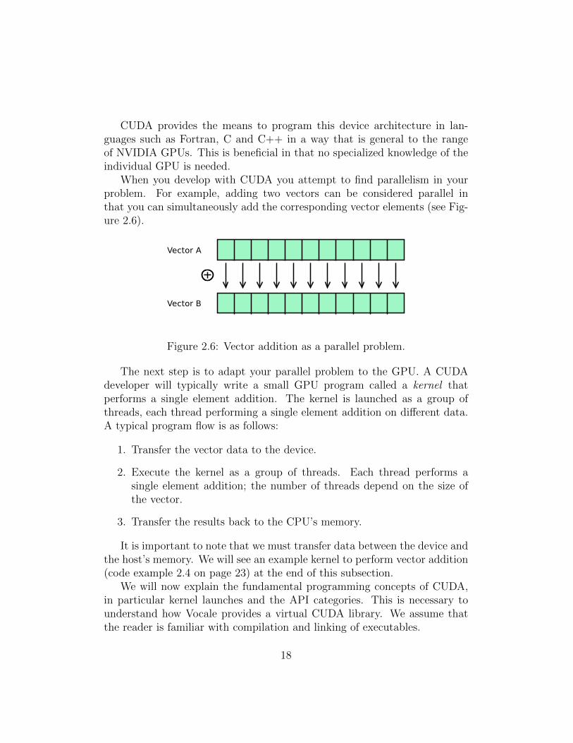
When you develop with CUDA you attempt to find parallelism in yourproblem. For example, adding two vectors can be considered parallel inthat you can simultaneously add the corresponding vector elements (see Fig-ure 2.6).
Figure 2.6: Vector addition as a parallel problem.
The next step is to adapt your parallel problem to the GPU. A CUDAdeveloper will typically write a small GPU program called a kernel thatperforms a single element addition. The kernel is launched as a group ofthreads, each thread performing a single element addition on different data.A typical program flow is as follows:
1. Transfer the vector data to the device.
2. Execute the kernel as a group of threads. Each thread performs asingle element addition; the number of threads depend on the size ofthe vector.
3. Transfer the results back to the CPU’s memory.
It is important to note that we must transfer data between the device andthe host’s memory. We will see an example kernel to perform vector addition(code example 2.4 on page 23) at the end of this subsection.
We will now explain the fundamental programming concepts of CUDA,in particular kernel launches and the API categories. This is necessary tounderstand how Vocale provides a virtual CUDA library. We assume thatthe reader is familiar with compilation and linking of executables.
18
Compilation and Linking
CUDA source files have the .cu suffix and consists of a mix of host and devicecode. Device code comprise code that is sent to the GPU for execution, andhost code encompass code that executes normally on the CPU. They aredistinguished by prefixing symbol names with device or global fordevice code, and host for host code.
Device code is executed on the GPU as Parallel Thread Execution (PTX)code or architecture specific binary code[8, Appendix G]. PTX code is a uni-fied assembly instruction set for all CUDA devices. It is guaranteed to besupported by any current or future CUDA device, regardless of the GPU’sarchitecture. When PTX compiled device code is launched, the CUDA driverwill perform just-in-time compilation to architecture specific code. Develop-ers can also steer compilation of device code to architecture specific (binary)code to avoid this.
Normal compilers such as gcc, the GNU compiler collection, does notknow what to do with the declaration specifiers for host and device code, nordoes it support compiling PTX or architecture specific code. To cope withthis, CUDA provides its own compiler, nvcc[7], that handles compilation ofCUDA specific code. The rest is left to the host compiler, which is normallygcc. Linking is performed without the need of external tools.
The CUDA API
The CUDA API is split in two: The driver API and the runtime API. Bothprovide similar functionality, but the runtime API is more easy to use, whilethe driver API is harder (but provides more fine grained control). Moreover,the runtime API is built on top of the driver API. This means that somedriver API functions are called implicitly when using the runtime API, forexample initialization and context routines.
The APIs contain functions for managing different aspects of the CUDAlibrary and any GPUs resident on the system. The following list describes themajor API categories, but readers are referenced to the CUDA programmingguide[8] and API reference manual[6] for full details. Some categories arealso omitted as they have not been tested in Vocale.
The CUDA runtime API is referenced through the cuda runtime.h
header file, and contains the following main API categories.
• Device Management. Get device properties, set the current device,
19

reset devices and others.
• Error Handling. Almost all API functions return an error type whichis specific to the API it belongs to. The exception is for example kernellaunches, and it is necessary to use functions like getLastError(..)
from this category.
• Stream Management. Many functions in the CUDA API, like kernellaunches and device memory transfers, can be run asynchronously in astream. Functions run in streams return immediately and are executedsequentially in their own thread. This category provides functions tocreate, query, destroy and synchronize streams.
• Event Management. Events can be used to record certain happen-ings in time. For example, an event can record when all or some of theoperations in a stream are complete to profile code.
• Execution Management. Functions for managing kernel launches.Apart from the Execution Configuration Syntax (ECS) covered below,kernels can be launched manually using a series of function calls in thiscategory.
• Memory Management. This category is quite extensive and coversa range of functions. These mainly enables us to allocate, transfer andfree device memory with 1 - , 2 - and 3 - dimensional data abstractions.Memory can also be transferred asynchronously using streams.
The CUDA driver API can be referenced through the cuda.h headerfile. It contains the following main API categories implemented and used byVocale.
• Context Management. SMs provide no memory protection in hard-ware like the virtual memory facilities of conventional CPUs. Instead,CUDA uses a software solution to prevent CUDA processes from acci-dentally reading or writing each other’s memories: Contexts. Contextscan be thought of as a process’ virtual memory; outside it, a process’kernels and device memory pointers have no meaning.
• Module and Execution Management. Provides, among otherthings, more fine grained control to load and launch kernels. Kernels
20
can for example be loaded from binary files or directly from memorypointers.
Kernels
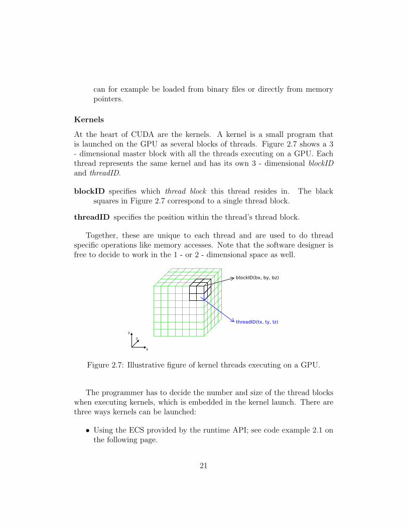
At the heart of CUDA are the kernels. A kernel is a small program thatis launched on the GPU as several blocks of threads. Figure 2.7 shows a 3- dimensional master block with all the threads executing on a GPU. Eachthread represents the same kernel and has its own 3 - dimensional blockIDand threadID.
blockID specifies which thread block this thread resides in. The blacksquares in Figure 2.7 correspond to a single thread block.
threadID specifies the position within the thread’s thread block.
Together, these are unique to each thread and are used to do threadspecific operations like memory accesses. Note that the software designer isfree to decide to work in the 1 - or 2 - dimensional space as well.
Figure 2.7: Illustrative figure of kernel threads executing on a GPU.
The programmer has to decide the number and size of the thread blockswhen executing kernels, which is embedded in the kernel launch. There arethree ways kernels can be launched:
• Using the ECS provided by the runtime API; see code example 2.1 onthe following page.
21

yourKernelName<<<numThreadBlocks , threadsPerThreadBlock>>>(
parameter1 ,parameter2 ,. . .
)
Code Example 2.1: Launching a kernel using the ECS.
cudaConf igureCal l (dim3 gridDim , dim3 blockDim , s ize t sharedMem ,cudaStream t stream )
cudaSetupArgument ( const void ∗arg , s ize t s i z e , s ize t o f f s e t )
cudaLaunch ( const char ∗ entry )
Code Example 2.2: Launching a kernel using the execution control functionsfrom the CUDA runtime API.
• Directly using the execution control functions provided by the runtimeAPI. These are relatively straightforward to use, but does the samework as the simpler ECS. They can be seen in code example 2.2.
These are called in sequence for each launch. cudaSetupArgument(..)is called as many times as there are arguments to the kernel.
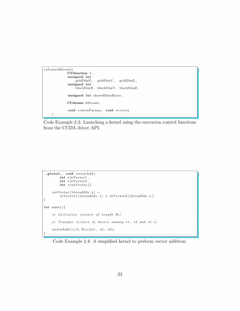
• Directly using the execution control functions provided by the driverAPI. This is the most flexible but hard to use. It supports importingdevice code from files and memory. Their function signatures can beseen in code example 2.3 on the following page.
As a very simple demonstration, consider code example 2.4 on the nextpage, which simply adds two vectors of size N using CUDA. The kernel,vectorAdd(..), is launched on the GPU with some memory pointers to thevectors as arguments. The number of threads launched corresponds to thenumber of elements in the vector. Note the use of the th read ID to accessthe correct memory areas. A real kernel would involve a block ID as well,but this is omitted for the sake of simplicity.
This sums up our presentation of CUDA. This section has given an intro-duction to the CUDA GPGPU framework, which is important to understandVocale’s job of virtualizing the CUDA library. In the next section, we willoutline the use of shared libraries and kernel modules.
22
cuLaunchKernel (CUfunction f ,unsigned int
gridDimX , gridDimY , gridDimZ ,unsigned int
blockDimX , blockDimY , blockDimZ ,
unsigned int sharedMemBytes ,
CUstream hStream ,
void ∗∗kernParams , void ∗∗ ext ra)
Code Example 2.3: Launching a kernel using the execution control functionsfrom the CUDA driver API.
global void vectorAdd (int ∗ inVector1 ,int ∗ inVector2 ,int ∗ outVector ) {
outVector [ threadIdx . x ] =inVector1 [ threadIdx . x ] + inVector2 [ threadIdx . x ] ;
}
int main ( ) {
/∗ I n i t i a l i z e v e c t o r s o f l en g t h N∗/
/∗ Transfer v e c t o r s to dev i ce memory v1 , v2 and v3 ∗/
vectorAdd<<<1, N>>>(v1 , v2 , v3 ) ;}
Code Example 2.4: A simplified kernel to perform vector addition.
23
2.4 Linux Libraries and Kernel Modules
The work presented in this thesis revolves a great deal around libraries anddrivers. Vocale is built in several iterations and involves three drivers andtwo libraries, so it makes sense to give a short introduction to these concepts.Again, we assume that the reader is familiar with compilation and linking ofexecutables in Linux.
2.4.1 Libraries
Libraries are collections of code, usually a compiled collection of subroutinesand symbols, that can be linked with other pieces of code. There are threetypes of libraries in Linux[29]:
Static libraries. These libraries have the .a (archive) suffix, and are linkedtogether with the executable in the linking phase.
Shared libraries. They have the .so (shared object) suffix. They areshared between programs, and are not linked before the referencingexecutable is run.
Dynamic libraries. Dynamic libraries are libraries that can be linked atany time during the run of the application.
The libraries developed in Vocale are of the shared type, so the rest ofthis section is devoted to them.
Using, Naming and Installing
Shared libraries follow a special naming convention. They have a real nameand an so-name, in addition to a library reference name. These providedevelopers with the means to version, expand and override libraries.
Figure 2.8 on the following page shows the relationships between all thesenames in a simple example. The first line is an invocation of gcc, requestingthe compilation and linking of the all-so-known helloworld.c. In additionto this, it has instructed the linker to include a shared library, sample, inthe linking phase.
The so-name is simply the library reference minus the preceding ’-l’,adding ’lib’ as prefix and ’.so.x’ as the suffix, where x is a version num-ber. When helloworld is executed, a loader program is run that starts
24
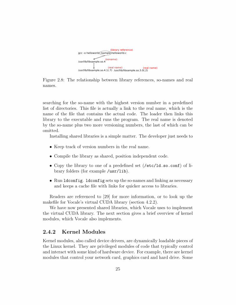
Figure 2.8: The relationship between library references, so-names and realnames.
searching for the so-name with the highest version number in a predefinedlist of directories. This file is actually a link to the real name, which is thename of the file that contains the actual code. The loader then links thislibrary to the executable and runs the program. The real name is denotedby the so-name plus two more versioning numbers, the last of which can beomitted.
Installing shared libraries is a simple matter. The developer just needs to
• Keep track of version numbers in the real name.
• Compile the library as shared, position independent code.
• Copy the library to one of a predefined set (/etc/ld.so.conf) of li-brary folders (for example /usr/lib).
• Run ldconfig. ldconfig sets up the so-names and linking as necessaryand keeps a cache file with links for quicker access to libraries.
Readers are referenced to [29] for more information, or to look up themakefile for Vocale’s virtual CUDA library (section 4.2.2).
We have now presented shared libraries, which Vocale uses to implementthe virtual CUDA library. The next section gives a brief overview of kernelmodules, which Vocale also implements.
2.4.2 Kernel Modules
Kernel modules, also called device drivers, are dynamically loadable pieces ofthe Linux kernel. They are privileged modules of code that typically controland interact with some kind of hardware device. For example, there are kernelmodules that control your network card, graphics card and hard drive. Some
25
kernel modules can also be controlled from user space. Under the /dev folderin Linux you will always find a number of such kernel modules, representedas special files in the file system (like zero, urandom and null).
Hypervisor technology will always involve kernel modules in some waysince they emulate a lot of hardware. Virtual hardware is also the naturalway to pass information in and out of VMs.
Kernel modules, like libraries, come in three groups[5]. They are groupedby the abstract format of the data they handle and the way in which theyare accessed.
Character devices. These are accessed as streams of bytes. Examples in-clude serial and parallel port drivers. They are represented as specialfiles in Linux’s file system.
Block devices. These are accessed by blocks of bytes, and control blockoriented hardware like optical media and hard drives. Like characterdevices, they are represented as special files.
Network devices. Packet oriented devices. Unlike the other driver types,they are not represented by files, but instead referenced by name (forexample wlan0).
This thesis only uses character devices, but we do not continue describingthem here. Kernel module development in general is a very complex process.It involves low level interfaces to hardware and the Linux kernel, and eachmodule type has different programming architecture. For now, it suffices toknow what they are. Interested readers are highly encouraged to read [5], aswell as look up the drivers developed as parts of Vocale. We will go in a bitmore detail about our driver implementation in Section 4.2.1.
With kernel modules explained, our next section revolves around theMMU. Understanding this component is important to understand the amountof copying and difficulties when exchanging data between hosts and guests.
2.5 The Memory Management Unit
The work done in this thesis requires the introduction of the MMU. Thiselectronic device makes a lot of trouble for VMs, especially in the context of
26

exchanging data between a VM and its hypervisor. Understanding the MMUis also important for anyone who wants to work further on Vocale.
The MMU is a part of all modern CPUs’ base electronic circuitry. In anutshell, the MMU is a hardware device that OSs use to implement virtualmemory and paging. As stated in Section 2.2.1, this is an abstraction forprocesses and OSs that creates the illusion of running in a private, separateaddress space.
Figure 2.9 shows two processes running in virtual memory, also calledthe user address space. They can access the same memory pointers withoutbothering the other, as the OS maps the virtual addresses to different physicaladdresses using the MMU.
Figure 2.9: Two processes running in separate, virtual address spaces.
Having this mapping results in several benefits that are typical to virtu-alization technology.
• Utility. Systems can create the illusion of having more main memorythan what is physically available. The MMU makes it possible to mapvirtual memory to external storage devices.
• Security. Processes run in their own environment with separate addressspaces and are protected from each other. A process’ memory buffershave no meaning in another, as it can only be accessed in the addressspace to which it belongs.
27
The mapping mechanism provided by the MMU is called paging. Thepaging mechanism is controlled by the OS and involves some rather complexwork with data structures and CPU registers. In the next subsection, wegive a brief overview of this system as it stands on x86 architecture. It isgood to know how these things work to understand our remarks on zero copyguest / host data exchanges presented in the final chapter. It is not requiredto read this to understand most of the thesis; so readers may just want toread the bullet points on the end of the subsection.
2.5.1 Paging
From the MMU’s point of view, physical memory is split into pages of a fixedlength. The length can vary depending on the OS implementation, but thecommon size is 4096 bytes.
The challenge of the MMU is to map virtual memory addresses to physicalones on a per process basis. To achieve this, each process is equipped with:
• Many page tables referencing physical memory. A process can poten-tially keep page tables for its entire 4 GB span of virtual memory.
• A single page directory referencing all the page tables.
Both data structures are 4096 bytes in length, exactly the size of a physicalpage. Figure 2.10 on the following page illustrates the translation from virtualaddresses to physical ones. The mapping is done as follows (we use VA forvirtual address and PA for physical address):
1. The process keeps a pointer to the base address of its page directory.This information is handled by the OS and is kept invisible to theprocess.
2. When the process makes a read / write access in its virtual addressspace, the MMU looks up the page directory for the process.
3. The first ten bytes of the accessed VA corresponds to a 4 byte offsetwithin the page directory. The MMU looks up this location and finds(among other, technical things) a base address pointer to one of manypage tables.
28
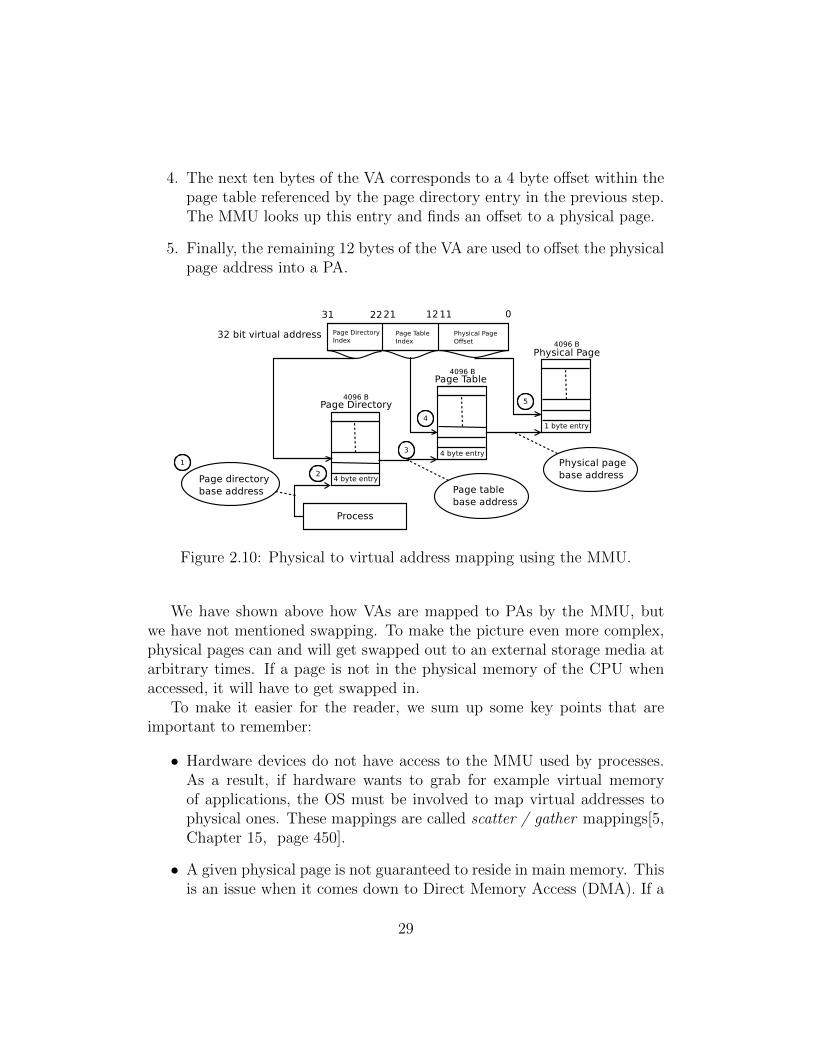
4. The next ten bytes of the VA corresponds to a 4 byte offset within thepage table referenced by the page directory entry in the previous step.The MMU looks up this entry and finds an offset to a physical page.
5. Finally, the remaining 12 bytes of the VA are used to offset the physicalpage address into a PA.
Figure 2.10: Physical to virtual address mapping using the MMU.
We have shown above how VAs are mapped to PAs by the MMU, butwe have not mentioned swapping. To make the picture even more complex,physical pages can and will get swapped out to an external storage media atarbitrary times. If a page is not in the physical memory of the CPU whenaccessed, it will have to get swapped in.
To make it easier for the reader, we sum up some key points that areimportant to remember:
• Hardware devices do not have access to the MMU used by processes.As a result, if hardware wants to grab for example virtual memoryof applications, the OS must be involved to map virtual addresses tophysical ones. These mappings are called scatter / gather mappings[5,Chapter 15, page 450].
• A given physical page is not guaranteed to reside in main memory. Thisis an issue when it comes down to Direct Memory Access (DMA). If a
29
hardware device wants to access virtual memory, the OS must somehowbe involved to lock memory in place.
• Even though a process ”sees” a contiguous, virtual memory layout, thememory is always scattered around in physical memory. This is calledmemory fragmentation. Hence, hardware devices do not usually havethe luxury of accessing large, continuous chunks of data.
This concludes the background information presented in this thesis. Thenext and final section outlines previous work in our research field.
2.6 Previous Work
This section outlines previous work in the field of GPU virtualization. Whilethere was relatively little work in this area at the time of the start of thethesis, some approaches were already proposed, and more have surfaced aswork progressed.
The first subsection gives a brief explanation about virtual GPU designparadigms given by VMware. The second subsection explains GViM, anapproach to a virtual CUDA library that Vocale is similar to. The lastsubsection outlines some of the development in GPU virtualization that hastranspired during the work of the thesis.
2.6.1 Virtual GPU Design Paradigms
Micah Dowty and Jeremy Sugerman from VMware outline different perfor-mance metrics and design paradigms for virtual GPUs[14]. Although theseare design paradigms for virtual GPUs, and not GPGPU technology, they arestill relevant to our design discussion of Vocale because the GPGPU facilitiesare embedded in physical GPUs.
Two ultimate design paradigms are established; front and back end vir-tualization. Front end virtualization encompass design paradigms where thehypervisor makes use of vendor provided drivers / APIs resident in the hostenvironment to provide GPU acceleration is some form to the VM. Two mainfront end techniques are outlined:
• API / Driver remoting. The hypervisor emulates a virtual API / Driverfor the VM’s OS, in which access to the physical GPU is mediatedthrough.
30
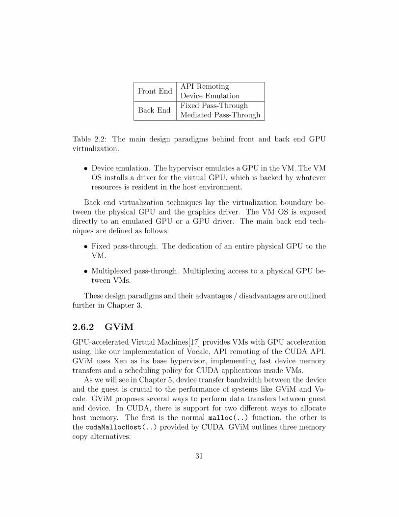
Front EndAPI RemotingDevice Emulation
Back EndFixed Pass-ThroughMediated Pass-Through
Table 2.2: The main design paradigms behind front and back end GPUvirtualization.
• Device emulation. The hypervisor emulates a GPU in the VM. The VMOS installs a driver for the virtual GPU, which is backed by whateverresources is resident in the host environment.
Back end virtualization techniques lay the virtualization boundary be-tween the physical GPU and the graphics driver. The VM OS is exposeddirectly to an emulated GPU or a GPU driver. The main back end tech-niques are defined as follows:
• Fixed pass-through. The dedication of an entire physical GPU to theVM.
• Multiplexed pass-through. Multiplexing access to a physical GPU be-tween VMs.
These design paradigms and their advantages / disadvantages are outlinedfurther in Chapter 3.
2.6.2 GViM
GPU-accelerated Virtual Machines[17] provides VMs with GPU accelerationusing, like our implementation of Vocale, API remoting of the CUDA API.GViM uses Xen as its base hypervisor, implementing fast device memorytransfers and a scheduling policy for CUDA applications inside VMs.
As we will see in Chapter 5, device transfer bandwidth between the deviceand the guest is crucial to the performance of systems like GViM and Vo-cale. GViM proposes several ways to perform data transfers between guestand device. In CUDA, there is support for two different ways to allocatehost memory. The first is the normal malloc(..) function, the other isthe cudaMallocHost(..) provided by CUDA. GViM outlines three memorycopy alternatives:
31

• The slowest alternative involves two copy operations. When the VM isstarted, a memory area is shared between the hypervisor and the guest’skernel space. The first copy is from the guest CUDA application’svirtual address space to the guest’s hypervisor-shared kernel memory.The next is the copy operation from the hypervisor-shared memory inthe host to the GPU. Data is copied using XenStore. Note that theXen Wiki states that the XenStore should not be used for large datatransfers[30].
• The next option proposes that guest CUDA applications use cudaMall-ocHost(..) to map the application’s virtual memory into the guest’shypervisor-shared kernel memory. This operation eliminates the needto copy data into the guest’s kernel memory and involves only one copyof data through to the GPU.
• The last strategy to accelerate device memory transfers is to allocatethe guest-shared hypervisor memory with cudaMallocHost, which at-tempts to pin the memory in place.
GViM is thus a paravirtualization approach, as to get the best bandwidthto and from the device, the programmer must use cudaMallocHost(..) toallocate host memory. The disadvantage of this approach is that not allprogrammers use this function, but rather the standard function malloc(..).Further, the third approach consumes a lot of the system’s main memory,because the memory is pinned and cannot be swapped out to an externalstorage media (refer to Section 2.5).
GViM’s approaches to these problems are undoubtedly the fastest possi-ble. The most optimal way to perform large memory transfers in and out ofVMs are zero copy transfers, that is, there is no copying involved in passingdata between the VM and its hypervisor. If one in addition can disregardphysical memory fragmentation and the standard copies between kernel anduser space, one will have eliminated almost all overhead incurred in thesetransfers.
In Vocale, we want to experiment with ways to perform memory trans-fers without having to resort to paravirtualization. This way, the developerdoes not need to rely on cudaMallocHost(..) to achieve acceptable devicememory transfer performance.
32
2.6.3 New Research and Development
During the work of this thesis, some new approaches to GPU virtualizationhave surfaced. Investigating these is out of scope for the thesis, but it isinteresting to see the direction of the development, which is sharing of PCI-Express devices among machines and dedicating hardware to VMs.
Xen Server 6, a server hypervisor released 8th March 2012, supports thededication of physical GPUs to VMs. Of course, no effort is done to multiplexaccess to the GPU, so it is locked to the VM that uses it. There has alsobeen development in Qemu, where developers are working on an OpenGLpass-through mechanism. OpenGL is a graphics library, but this work issimilar to what Vocale does.
There have also been development on the hardware layer. PCI-SIG, thePCI Special Interest Group, has come up with a new standard for sharing ofPCI-Express devices[16]. This is a very interesting development as there hasnot been hardware support for sharing hardware devices before.
This concludes our background chapter. We will now go into the designdiscussion and architecture of Vocale.
33
Chapter 3
Vocale - Design andArchitecture
Vocale is an acronym for Virtual CUDA Library Extension. It is a composi-tion of programs, libraries and drivers built on top of the Qemu hypervisor,designed and implemented as a part of this thesis. Its main goal is to provideapplications in VMs with GPU acceleration, which is done by virtualizingthe CUDA library. This chapter outlines the design discussion and high-levelarchitecture of Vocale.
Vocale is built in two stages, 1.x and 2.x. The difference in these ver-sions is how they implement data transfers between the host and the guest;other than that, they keep the same modular structure. The reason for re-implementing data transfers is that Vocale 1.x’s transfer bandwidth is veryslow. Vocale 1.x also causes a bug in the VM that halts the virtual CPU(refer to Section 5.2.2 and 5.3.1 for details). This chapter does not explainthe difference between the versions, but their common design and softwarearchitecture.
The chapter layout is as follows. The first section in this chapter presentsthe overall design goals of Vocale.
The following section discusses the design choices made for Vocale. Theseinclude where the virtualization boundary is laid, which hypervisor is usedfor development and the OS which will be run in the host and the guest.
The third and final section introduces the modular architecture of Vo-cale, where each of the building blocks of Vocale and their interfaces areintroduced. We will also have a look at the most central data structures inVocale. This leads up to the implementation specific details in Chapter 4.
34
3.1 Design Goals
There were several design goals with the development of Vocale. These mergewith the goals of the thesis (see Section 1.1) and are focused more on im-plementation evaluation and testing than the perfection of the system. Themain design goals are as follows:
• To enable VMs with GPU acceleration in some form of a virtual GPU.The applications running in the VM need to be able to benefit fromGPU acceleration (assuming that the GPU resource is backed by thehost).
• Efficiency. In order for systems like Vocale to be competitive it needs tomeet the near native performance standards set by the original system.
• Program modularity. Vocale and its components may change in thefuture; thus it needs well defined interfaces between its various com-ponents. It is also important to be able to test individual modulesindependently if necessary.
• Hypervisor flexibility. Vocale will be built partly in a hypervisor, anddepends on the facilities provided by it in order to meet the designgoals. The hypervisor needs to provide a rich set of tools that can beused to experiment with the implementation.
With the design goals explained, we can now start discussing the mostimportant design choices of Vocale.
3.2 Design Discussion
This section discusses the design choices made for Vocale with respect to thedesign goals which have been defined in the previous section. In summary,we want to decide the following:
• What do we want to virtualize to bring GPU acceleration to VMs?We call this the virtualization boundary. We review VMware’s designparadigms (see Section 2.6.1) for virtual GPUs.
• Platform specific details, like the OS to use for development.
35

• Hypervisor platform. There are several hypervisors available, and wewish to evaluate which one suits our needs best.
3.2.1 Virtualization Boundary
In order to provide GPU acceleration to a VM, the initial design choice ofVocale is to define the virtualization boundary. This boundary represents theinterface in which virtualization takes place. Two main design paradigms aredefined by VMware that we can use in this discussion: Front and back end.For example, back end paradigms target virtualization of physical GPUs anddrivers, while front end paradigms target drivers and software libraries /APIs.
Fixed Pass-Through
Let us consider the back end paradigms first, starting with fixed pass-through.This approach dedicates a physical GPU to the VM: The host will not at-tempt to claim it for itself, but will allow the VM to control it. The point ofthis is that the VM can install any vendor provided drivers and libraries tocontrol the device; see Figure 3.1 on the next page.
Back end virtualization may seem like a correct approach. The GPU isa hardware device, and thus it should be emulated as hardware. It givesOSs the opportunity to benefit from it, as OSs cannot directly use softwarelibraries. It is also the only way to provide a full virtualization solution (referto Section 2.2.2).
Implementing and maintaining this, however, is not trivial. ModernGPUs use the PCI-Express bus to interface with the processor, so we need toemulate this high-speed bus in the VM. The PCI-E specification also costsmoney, and we may need this if there is no framework for virtual PCI-Expressdevices in existing hypervisors.
While we do not know any details about PCI-E, we can still imagineproblems related to this task. An issue that will arise in this scenario iswhen one of the GPU accelerated processes in a VM attempts to performa device memory transfer. The physical GPU can typically perform DMAin the physical memory of the host. The GPU driver which is running inthe guest, however, will create DMA mappings from virtual memory to thephysical memory of the guest. The problem is that these DMA mappingshold no correspondence with the physical memory of the host, so when the
36
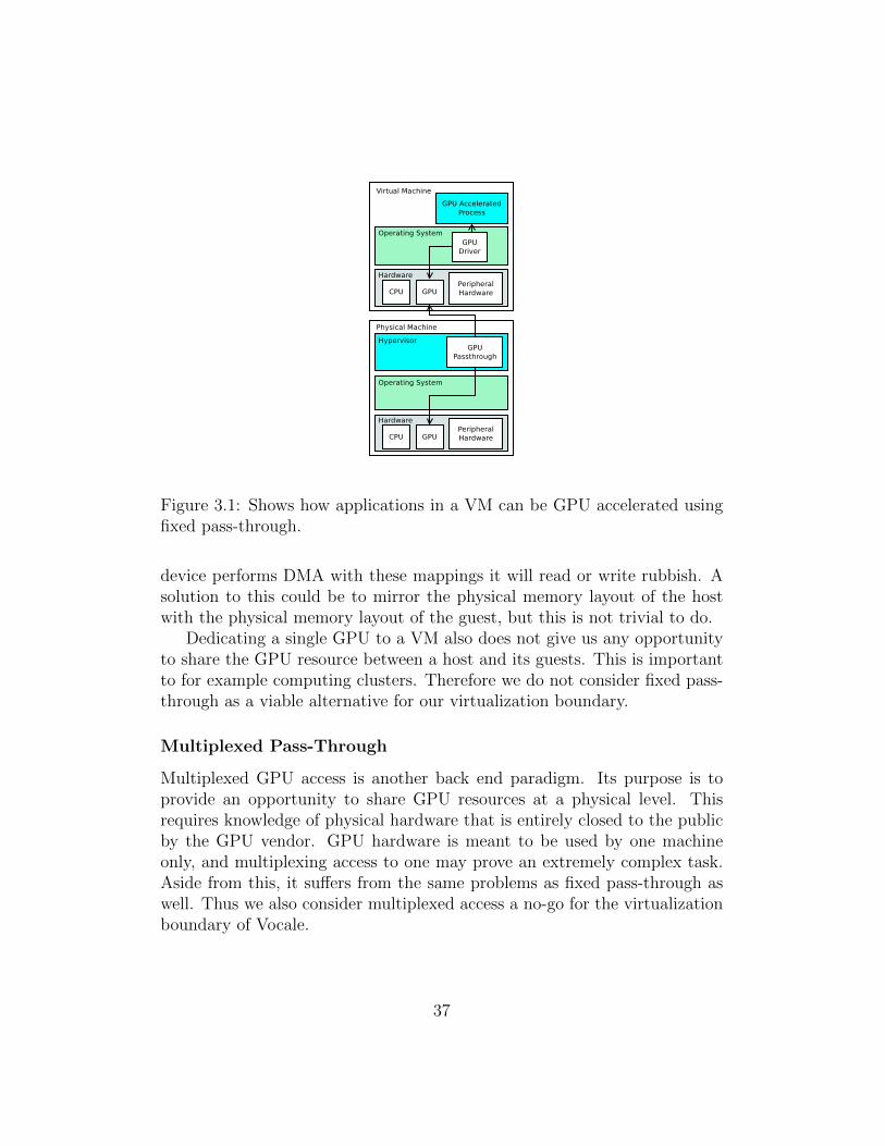
Figure 3.1: Shows how applications in a VM can be GPU accelerated usingfixed pass-through.
device performs DMA with these mappings it will read or write rubbish. Asolution to this could be to mirror the physical memory layout of the hostwith the physical memory layout of the guest, but this is not trivial to do.
Dedicating a single GPU to a VM also does not give us any opportunityto share the GPU resource between a host and its guests. This is importantto for example computing clusters. Therefore we do not consider fixed pass-through as a viable alternative for our virtualization boundary.
Multiplexed Pass-Through
Multiplexed GPU access is another back end paradigm. Its purpose is toprovide an opportunity to share GPU resources at a physical level. Thisrequires knowledge of physical hardware that is entirely closed to the publicby the GPU vendor. GPU hardware is meant to be used by one machineonly, and multiplexing access to one may prove an extremely complex task.Aside from this, it suffers from the same problems as fixed pass-through aswell. Thus we also consider multiplexed access a no-go for the virtualizationboundary of Vocale.
37
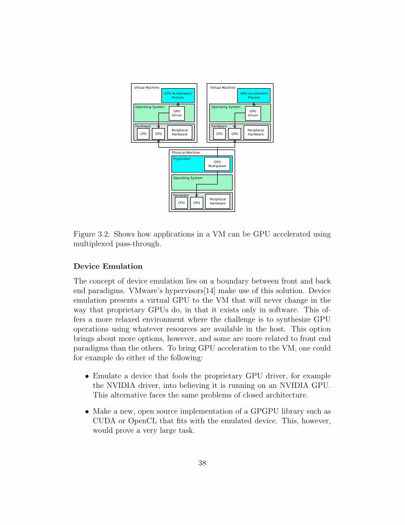
Figure 3.2: Shows how applications in a VM can be GPU accelerated usingmultiplexed pass-through.
Device Emulation
The concept of device emulation lies on a boundary between front and backend paradigms. VMware’s hypervisors[14] make use of this solution. Deviceemulation presents a virtual GPU to the VM that will never change in theway that proprietary GPUs do, in that it exists only in software. This of-fers a more relaxed environment where the challenge is to synthesize GPUoperations using whatever resources are available in the host. This optionbrings about more options, however, and some are more related to front endparadigms than the others. To bring GPU acceleration to the VM, one couldfor example do either of the following:
• Emulate a device that fools the proprietary GPU driver, for examplethe NVIDIA driver, into believing it is running on an NVIDIA GPU.This alternative faces the same problems of closed architecture.
• Make a new, open source implementation of a GPGPU library such asCUDA or OpenCL that fits with the emulated device. This, however,would prove a very large task.
38
While we consider device emulation more interesting, our proposals aboveeither involves massive amounts of work or faces the same problems as backend paradigms. Our final proposal is a pure front end technique called remoteprocedure calling.
Remote Procedure Calling
Figure 3.3: Shows how applications in a VM can be GPU accelerated usingremote procedure calling.
Front end techniques in general are much more interesting for Vocale,because they leave the hardware layer behind and targets direct virtualizationof drivers and libraries. While drivers often suffer from proprietary details,software libraries generally have some kind of API that is known to the public.Knowing the API of the library or driver, it is possible to implement a fakeversion of it and remotely call the real interface in the host (see Figure 3.3).
For example, if an existing library has two functions, remote(..) andgpu(..), a virtual library implementation in the guest would implementthose two and forward them to the real one in the host. The calls andcallbacks are sent across the guest / host boundary to service requests fromthe VM’s user space.
Using remote procedure calling, details and internal workings of the driver
39
/ library can be left out to a large degree, owing to the fact that we onlyforward and return function calls. To the contrary of back end virtualization,these systems have the potential for easy maintenance as the vendor itself willmanage hardware support and backward compatibility. The only concernwith these solutions is that, depending on the library functionality, someknowledge of the internal workings of the library may be necessary. Note thatthese solutions center around a paravirtualized approach. This is becausethe virtual library or driver needs to know that it is running in a virtualenvironment to operate.
Because of this, Vocale implements GPU acceleration by the front enddesign paradigm, remote procedure calling, of a GPGPU library. Refer toTable 3.1 on the next page and 3.2 on page 42 for a summary of the pointsabove.
Now that we have decided to virtualize a GPGPU library using remoteprocedure calling, the next question is what library we will emulate, and onwhat OS platform.
3.2.2 OS Platform and Library
In this section, we will discuss which GPGPU library we will emulate in Vo-cale. We also decide which OS platform we want to base the implementationon.
GPU acceleration is provided through two commonly known libraries,OpenCL and CUDA. We will focus on emulating CUDA, as both OpenCLand CUDA are similar in architecture, and the writer is more familiar withthe latter.
Since we are to implement our own, virtual, CUDA library, we need toestablish some minimum design goals for it as well.
• Developers should be able to invoke nvcc (refer to Section 2.3.1) asusual to compile and link CUDA applications.
• Function calls must be working (refer to Section 2.3.1).
• The guest must be able to execute kernels.
• The guest must be able to perform device memory transfers.
The project needs to handle two OSs; one for the host and one for theguest. Our implementation will involve virtual hardware, and that means
40

Advantages DisadvantagesFixed
Passthrough- Full virtualization.
- Vendor handles drivers andlibraries.
- Need to know PCI-Expressdetails.
- Need to know GPU specifichardware details.
- No GPU sharing.
- DMA may be hard toachieve because of the VM’sMMU.
- Proprietary, ever changingGPU architectures.
MultiplexedPassthrough
- Full virtualization.
- Vendor handles drivers andlibraries.
- Shared GPU resource.
- Same disadvantages as forfixed pass-through.
- GPUs are not meant to beshared in hardware.
Table 3.1: Overview of advantages and disadvantages of back end designparadigms.
41
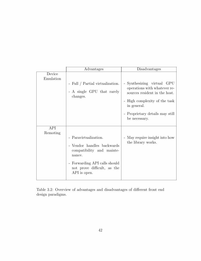
Advantages DisadvantagesDevice
Emulation- Full / Partial virtualization.
- A single GPU that rarelychanges.
- Synthesizing virtual GPUoperations with whatever re-sources resident in the host.
- High complexity of the taskin general.
- Proprietary details may stillbe necessary.
APIRemoting
- Paravirtualization.
- Vendor handles backwardscompatibility and mainte-nance.
- Forwarding API calls shouldnot prove difficult, as theAPI is open.
- May require insight into howthe library works.
Table 3.2: Overview of advantages and disadvantages of different front enddesign paradigms.
42
working with device drivers. Using Linux provides us with free hands toexperiment. We want to use the 64 bit version of Ubuntu in both the hostand the guest, which helps coping with architecture difficulties that can occurbetween for example 32 - and 64 - bit systems and systems with differentbyte-order endianness.
3.2.3 Hypervisor Platform
We have chosen to emulate CUDA in a VM to provide the VM’s applicationswith GPU acceleration. In the last subsection, we determined to use theUbuntu Linux distribution as our OS of choice for the guest and the host.
The last part of the design discussion revolves around the choice of hy-pervisor. The hypervisor is an important part of the design because functioncalls and callbacks between the host and the guest will take place throughit. In other words, part of the implementation will be an extension to thehypervisor to allow for host - guest communication.
Unfortunately, both proprietary and open source hypervisors are not verywell documented, and information about them has been hard to find. As theQemu developers say, ”only the source code tells the full story”[24]. Also, wehave experienced that information often is out of date, and as we have saidearlier there has been research and development in our field during the workof the thesis.
There exists some work that attempts to outline the main differencesbetween them[20], and we will attempt to make use of this. The followinglist summarizes our criteria for Vocale’s base hypervisor.
• The hypervisor is active, that is, under constant development andbacked by a developer community.
• Linux support, following our discussion in the previous subsection.
• Open source and as good documentation as possible.
• A type 2 hypervisor (refer to Section 2.2.3) for easier debugging andsystem architecture; we believe it is hard to debug a program directlyon hardware.
• Not been the target of previous work in the area of remote procedurecalling of the CUDA library.
43

• A rich set of tools to facilitate data transfers between the guest andthe host.
We will now argument for our choice of hypervisor.Xen is a popular, fast and reliable; however it is also a type 2 hypervisor.
The need to modify guest OSs depending on the virtualization capabilitiesof the hardware could pose a problem if we want to test the implementa-tion on different OSs. Despite this, Xen represents an opportunity to sharecomputational resources. Unfortunately, the GViM project[17] has alreadyimplemented CUDA forwarding in this hypervisor.
VMware hosts a number of virtualization solutions, including one opensource type 1 hypervisor named VMware Player. VMware Player is claimedto achieve great performance, but we could not find much documentation interms of internal functionality and design.
VirtualBox is a Type 1 hypervisor for both Windows and Linux anddoesn’t really have any disadvantages as long as the host computer supportsvirtualization in hardware. This makes it a viable option for implementationof GPU virtualization.
Qemu is an open source Type 1 hypervisor for Linux. It is documentedto some degree and suitable for self-study, with a supporting developer com-munity behind it. We have also noted that it is used by other hypervisors,like Xen, to implement virtual hardware. This leads us to believe that ithas a good internal framework for virtual hardware. Since it is made forLinux, experimenting with for example DMA is easier than on for exampleWindows. Qemu also supports KVM which is a kernel module that booststhe performance of the hypervisor.
As we have said, finding good, up to date information about these hyper-visors has been hard. One has to actually study the source code to be ableto find detailed information. We believe that Qemu will be able to suit ourneeds. This is mainly due to the fact that researchers state that its hard-ware model is being used by other hypervisors. We think Xen would also bea good choice, as it is used for server virtualization and relevant for cloudcomputing. But since Xen has already been the target of GPU virtulizationin the GViM project, we choose to work with Qemu.
With our high level design choices made, we can start outlining Vocale’ssoftware architecture.
44

3.3 Vocale - Architecture
As we have stated in the beginning of this chapter, Vocale is built in twoiterations. Regardless of version, however, Vocale keeps an identical, modu-lar structure to accommodate change. This is one of Vocale’s design goals.Figure 3.4 on the next page shows all the main components of Vocale in arunning system. Starting from top to bottom, we now describe each of them.
CUDA Application. A normal CUDA process running in the guest OS.It runs and operates just like it would in a real, non-virtual CUDAenvironment (full virtualization).
Virtual CUDA library. Our implementation of the CUDA library. Itsmain purpose is to forward function calls and kernel launches to theCUDA forwarder described below. CUDA code can compile and linkas normal towards this library by invocation of nvcc (refer to Section2.3.1).
Transfer Library. A shared library implementing a simple interface fortransferring data to and from the host.
Data Path. The data path provides a line of communication between thehost and the guest. It is always implemented as virtual Input / Output(I/O) hardware, as this is the natural way for a CPU to communicatewith the outside world. The data path is complex in sense that itrequires an implementation in both the host (Qemu) and the guest OS(a driver). For example, virtual hardware like a PCI device needs adriver in the guest OS as well as an implementation in Qemu.
CUDA forwarder. The CUDA forwarder is responsible for forwarding func-tion calls, data and kernel launches to the real CUDA library. It alsopasses back any results, also called the callback, to the guest.
CUDA Library. This is the real, proprietary CUDA library. The forwarderlinks to it like a normal CUDA application to accomplish its tasks.
CUDA Driver. The real, proprietary CUDA driver. It is used by theCUDA library to communicate with the physical GPU.
Vocale can be split in three parts following the list above.
45

Figure 3.4: The general architecture of Vocale.
46
1. The virtual CUDA library.
2. The data path.
3. The CUDA forwarder.
The following subsections describe their architecture in closer detail, andleads up to the implementation specific details in the next chapter.
3.3.1 Virtual CUDA Library
The virtual CUDA library imposes the role of the real one as provided byNVIDIA. When installed in the guest OS, it will enable guest CUDA appli-cations to use the host’s GPU for computation. The virtual library shouldbe a full virtualization system, that is, its users should be able to use it with-out requiring any knowledge they are running on a virtual system (refer toSection 2.2.2). CUDA API calls and kernel launches should be interceptedby the virtual library and sent to the CUDA forwarder (described furtheron in Section 3.3.3). The forwarder executes the call or kernel launch andpasses back the result.
All references to the CUDA API is done through two NVIDIA providedheaders: cuda.h and cuda runtime.h. These must also be included by thevirtual library to implement the relevant API functions declared in the head-ers. It is compiled and installed as a shared library (refer to Section 2.4.1).
It is not required, nor desirable, to override all the API functions andmechanisms of CUDA. For example, we do not want to override kernel codecompilation (refer to Section 2.3.1) or device specific math functions. Thevirtual library should only override the functionality that requires the pres-ence of a physical GPU. This means that the proprietary CUDA library mustbe installed alongside the virtual library, overriding only the required func-tionality and letting its real counterpart do the rest. Fortunately, Linux’sshared library implementation is designed just for these purposes, and it iseasy to override a selection of functions from a library.
Function call forwarding and result callback is done by passing a datastructure containing any input and/or output parameters of the desired func-tion along with a call header. This data structure can be seen in code exam-ple 3.1 on the following page. The following list describes its fields.
47
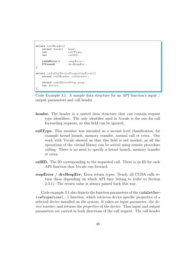
struct ca l lHeader {struct header head ;int ca l lType ;int ca l l ID ;
cudaError t r e spError ;CUresult drvRespErr ;
} ;
struct cudaGetDev icePropert i e sStruct {struct ca l lHeader c a l l h e ad e r ;
struct cudaDeviceProp prop ;int dev i ce ;
} ;
Code Example 3.1: A sample data structure for an API function’s input /output parameters and call header.
header. The header is a nested data structure that can contain requesttype identifiers. The only identifier used in Vocale is the one for callforwarding requests, so this field can be ignored.
callType. This member was intended as a second level classification, forexample kernel launch, memory transfer, normal call et cetra. Ourwork with Vocale showed us that this field is not needed, as all theoperations of the virtual library can be solved using remote procedurecalling. There is no need to specify a kernel launch, memory transferet cetra.
callID. The ID corresponding to the requested call. There is an ID for eachAPI function that Vocale can forward.
respError / drvRespErr. Error return types. Nearly all CUDA calls re-turn these depending on which API they belong to (refer to Section2.3.1). The return value is always passed back this way.
Code example 3.1 also depicts the function parameters of the cudaGetDev-iceProperties(..) function, which retrieves device specific properties of aselected device installed on the system. It takes an input parameter, the de-vice number, and returns the properties of the device. Thus input and outputparameters are carried in both directions of the call request. The call header
48
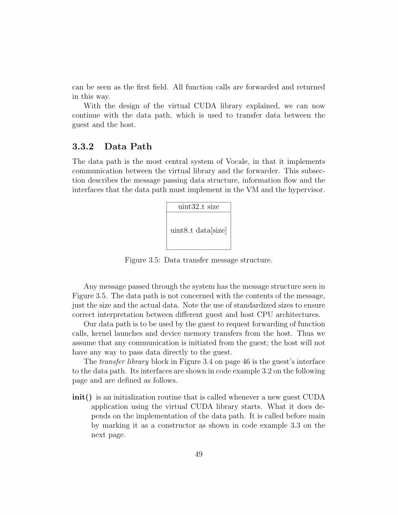
can be seen as the first field. All function calls are forwarded and returnedin this way.
With the design of the virtual CUDA library explained, we can nowcontinue with the data path, which is used to transfer data between theguest and the host.
3.3.2 Data Path
The data path is the most central system of Vocale, in that it implementscommunication between the virtual library and the forwarder. This subsec-tion describes the message passing data structure, information flow and theinterfaces that the data path must implement in the VM and the hypervisor.
uint32 t size
uint8 t data[size]
Figure 3.5: Data transfer message structure.
Any message passed through the system has the message structure seen inFigure 3.5. The data path is not concerned with the contents of the message,just the size and the actual data. Note the use of standardized sizes to ensurecorrect interpretation between different guest and host CPU architectures.
Our data path is to be used by the guest to request forwarding of functioncalls, kernel launches and device memory transfers from the host. Thus weassume that any communication is initiated from the guest; the host will nothave any way to pass data directly to the guest.
The transfer library block in Figure 3.4 on page 46 is the guest’s interfaceto the data path. Its interfaces are shown in code example 3.2 on the followingpage and are defined as follows.
init() is an initialization routine that is called whenever a new guest CUDAapplication using the virtual CUDA library starts. What it does de-pends on the implementation of the data path. It is called before mainby marking it as a constructor as shown in code example 3.3 on thenext page.
49
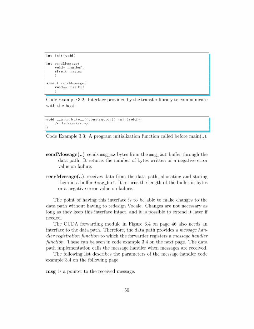
int i n i t (void )
int sendMessage (void∗ msg buf ,s ize t msg sz)
s ize t recvMessage (void∗∗ msg buf)
Code Example 3.2: Interface provided by the transfer library to communicatewith the host.
void a t t r i b u t e ( ( con s t ruc to r ) ) i n i t (void ) {/∗ I n i t i a l i z e ∗/
}
Code Example 3.3: A program initialization function called before main(..).
sendMessage(..) sends msg_sz bytes from the msg_buf buffer through thedata path. It returns the number of bytes written or a negative errorvalue on failure.
recvMessage(..) receives data from the data path, allocating and storingthem in a buffer *msg_buf. It returns the length of the buffer in bytesor a negative error value on failure.
The point of having this interface is to be able to make changes to thedata path without having to redesign Vocale. Changes are not necessary aslong as they keep this interface intact, and it is possible to extend it later ifneeded.
The CUDA forwarding module in Figure 3.4 on page 46 also needs aninterface to the data path. Therefore, the data path provides a message han-dler registration function to which the forwarder registers a message handlerfunction. These can be seen in code example 3.4 on the next page. The datapath implementation calls the message handler when messages are received.
The following list describes the parameters of the message handler codeexample 3.4 on the following page.
msg is a pointer to the received message.
50
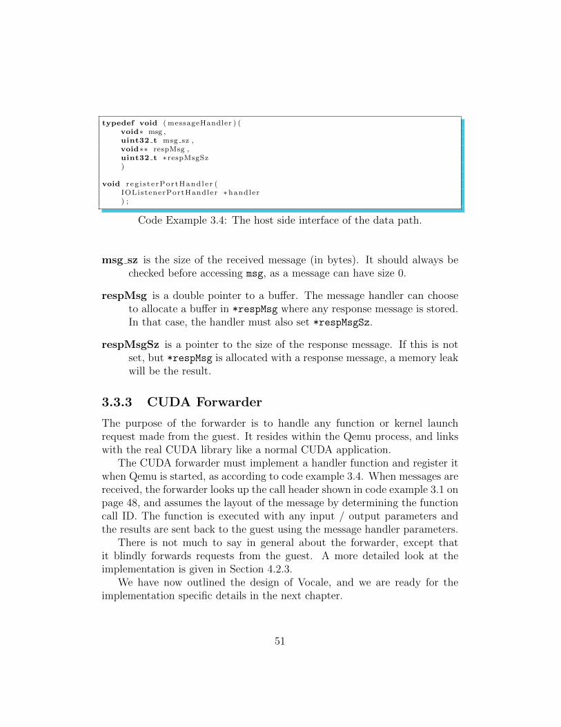
typedef void ( messageHandler ) (void∗ msg ,uint32 t msg sz ,void∗∗ respMsg ,uint32 t ∗ respMsgSz)
void r eg i s t e rPo r tHand l e r (IOListenerPortHandler ∗handler) ;
Code Example 3.4: The host side interface of the data path.
msg sz is the size of the received message (in bytes). It should always bechecked before accessing msg, as a message can have size 0.
respMsg is a double pointer to a buffer. The message handler can chooseto allocate a buffer in *respMsg where any response message is stored.In that case, the handler must also set *respMsgSz.
respMsgSz is a pointer to the size of the response message. If this is notset, but *respMsg is allocated with a response message, a memory leakwill be the result.
3.3.3 CUDA Forwarder
The purpose of the forwarder is to handle any function or kernel launchrequest made from the guest. It resides within the Qemu process, and linkswith the real CUDA library like a normal CUDA application.
The CUDA forwarder must implement a handler function and register itwhen Qemu is started, as according to code example 3.4. When messages arereceived, the forwarder looks up the call header shown in code example 3.1 onpage 48, and assumes the layout of the message by determining the functioncall ID. The function is executed with any input / output parameters andthe results are sent back to the guest using the message handler parameters.
There is not much to say in general about the forwarder, except thatit blindly forwards requests from the guest. A more detailed look at theimplementation is given in Section 4.2.3.
We have now outlined the design of Vocale, and we are ready for theimplementation specific details in the next chapter.
51
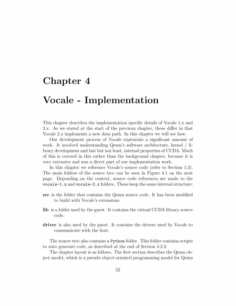
Chapter 4
Vocale - Implementation
This chapter describes the implementation specific details of Vocale 1.x and2.x. As we stated at the start of the previous chapter, these differ in thatVocale 2.x implements a new data path. In this chapter we will see how.
Our development process of Vocale represents a significant amount ofwork. It involved understanding Qemu’s software architecture, kernel / li-brary development and last but not least, internal properties of CUDA. Muchof this is covered in this rather than the background chapter, because it isvery extensive and was a direct part of our implementation work.
In this chapter we reference Vocale’s source code (refer to Section 1.3).The main folders of the source tree can be seen in Figure 4.1 on the nextpage. Depending on the context, source code references are made to thevocale-1.x and vocale-2.x folders. These keep the same internal structure:
src is the folder that contains the Qemu source code. It has been modifiedto build with Vocale’s extensions.
lib is a folder used by the guest. It contains the virtual CUDA library sourcecode.
driver is also used by the guest. It contains the drivers used by Vocale tocommunicate with the host.
The source tree also contains a Python folder. This folder contains scriptsto auto generate code, as described at the end of Section 4.2.2.
The chapter layout is as follows. The first section describes the Qemu ob-ject model, which is a pseudo object-oriented programming model for Qemu
52
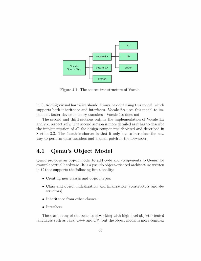
Figure 4.1: The source tree structure of Vocale.
in C. Adding virtual hardware should always be done using this model, whichsupports both inheritance and interfaces. Vocale 2.x uses this model to im-plement faster device memory transfers - Vocale 1.x does not.
The second and third sections outline the implementation of Vocale 1.xand 2.x, respectively. The second section is more detailed as it has to describethe implementation of all the design components depicted and described inSection 3.3. The fourth is shorter in that it only has to introduce the newway to perform data transfers and a small patch in the forwarder.
4.1 Qemu’s Object Model
Qemu provides an object model to add code and components to Qemu, forexample virtual hardware. It is a pseudo object-oriented architecture writtenin C that supports the following functionality:
• Creating new classes and object types.
• Class and object initialization and finalization (constructors and de-structors).
• Inheritance from other classes.
• Interfaces.
These are many of the benefits of working with high level object orientedlanguages such as Java, C++ and C#, but the object model is more complex
53
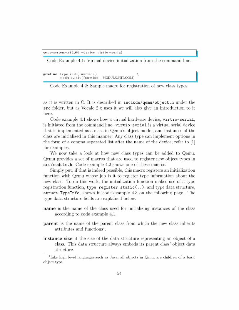
qemu−system−x86 64 −dev i ce v i r t i o−s e r i a l
Code Example 4.1: Virtual device initialization from the command line.
#define t y p e i n i t ( f unc t i on ) \modu l e in i t ( funct ion , MODULE INIT QOM)
Code Example 4.2: Sample macro for registration of new class types.
as it is written in C. It is described in include/qemu/object.h under thesrc folder, but as Vocale 2.x uses it we will also give an introduction to ithere.
Code example 4.1 shows how a virtual hardware device, virtio-serial,is initiated from the command line. virtio-serial is a virtual serial devicethat is implemented as a class in Qemu’s object model, and instances of theclass are initialized in this manner. Any class type can implement options inthe form of a comma separated list after the name of the device; refer to [1]for examples.
We now take a look at how new class types can be added to Qemu.Qemu provides a set of macros that are used to register new object types insrc/module.h. Code example 4.2 shows one of these macros.
Simply put, if that is indeed possible, this macro registers an initializationfunction with Qemu whose job is it to register type information about thenew class. To do this work, the initialization function makes use of a typeregistration function, type_register_static(..), and type data structure,struct TypeInfo, shown in code example 4.3 on the following page. Thetype data structure fields are explained below.
name is the name of the class used for initializing instances of the classaccording to code example 4.1.
parent is the name of the parent class from which the new class inheritsattributes and functions1.
instance size it the size of the data structure representing an object of aclass. This data structure always embeds its parent class’ object datastructure.
1Like high level languages such as Java, all objects in Qemu are children of a basicobject type.
54

Type t y p e r e g i s t e r s t a t i c ( const TypeInfo ∗ i n f o ) ;
struct TypeInfo{
/∗ Some members are omit ted f o r s imp l i c i t y ∗/
const char ∗name ;const char ∗parent ;
s ize t i n s t a n c e s i z e ;void (∗ i n s t a n c e i n i t ) ( Object ∗ obj ) ;void (∗ i n s t a n c e f i n a l i z e ) ( Object ∗ obj ) ;
s ize t c l a s s s i z e ;void (∗ c l a s s i n i t ) (ObjectClass ∗ k la s s , void ∗data ) ;void (∗ c l a s s f i n a l i z e ) (ObjectClass ∗ k la s s , void ∗data ) ;
} ;
Code Example 4.3: The data structure used to register information aboutnew object types.
instance init and instance finalize are function pointers to the instanceconstructor and destructor of a class. These are called when new ob-jects are created and killed.
class size is the size of the data structure representing a class. This datastructure always embeds its parent class’ class data structure.
class init and class finalize are function pointers to the class constructorand destructor.
The job involved in creating new object types is thus to implement allthe above functions. In addition to initializing itself, it is the constructors’responsibility to override any inherited functions from parental classes andobjects. Examples of this can be seen in Section 4.3.
We will get back to the Qemu object model in Section 4.3, but first wewill describe the implementation of Vocale 1.x.
4.2 Vocale 1.x
The initial implementation of Vocale is based on Qemu version 0.15.x. Allfile references are to the vocale-1.x folder of the source tree as described in
55
the beginning of this chapter. This section goes into implementation specificdetails of Vocale 1.x according to the architecture outlined in Section 3.3.
Vocale 1.x implements the virtual CUDA library, a data path using I/Oports and the CUDA forwarder in Qemu. Figure 4.2 on the following pageshows an overview of the implementation, which is very similar to the figuregiven in Section 3.3 on page 46.
The next subsections describe the three components that Vocale 1.x im-plements.
1. The data path. It consists of the IOlistener Driver, the IOlistenerVirtual Device and the Transfer Library blocks in Figure 4.2 onthe next page. We want to describe this component first because it iscentral to the two others.
2. The virtual CUDA library. It consists of the Virtual CUDA Library
block in Figure 4.2 on the following page. We describe how it capturesCUDA API calls and kernel launches.
3. Finally, the CUDA Forwarding Module is explained. The forwarder ex-ecutes CUDA calls and kernel launches natively on the real CUDAlibrary.
4.2.1 Data Path
One of the challenges of Vocale is to be able to pass data between the hostand the guest. To do this it is necessary to exploit the natural ways in whicha computer exchanges data with the outside world: In other words, hardware.Modern computers host GPUs, USB controllers and network devices, all ofwhich are able to transmit data in and out of the computer.
Our requirement is to be able to pass data from the guest CPU’s mainmemory to the main memory of the host. At a low level, one might saythat all memory used by the guest and the host reside in the same physicalmemory (unless it is being swapped out). The reason we cannot directlyshare this memory is because of the MMU of modern processors (refer toSection 2.5). The MMU creates several distinct address spaces. One for eachprocess and OS in the guest and the host. We cannot directly pass memorybetween these worlds, because memory pointers in one address space has nomeaning in another (remember Figure 2.9 on page 27). So the only solution
56

Figure 4.2: The implementation specific components of Vocale 1.x.
57
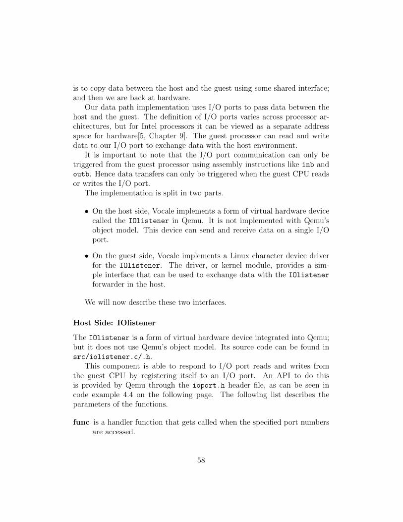
is to copy data between the host and the guest using some shared interface;and then we are back at hardware.
Our data path implementation uses I/O ports to pass data between thehost and the guest. The definition of I/O ports varies across processor ar-chitectures, but for Intel processors it can be viewed as a separate addressspace for hardware[5, Chapter 9]. The guest processor can read and writedata to our I/O port to exchange data with the host environment.
It is important to note that the I/O port communication can only betriggered from the guest processor using assembly instructions like inb andoutb. Hence data transfers can only be triggered when the guest CPU readsor writes the I/O port.
The implementation is split in two parts.
• On the host side, Vocale implements a form of virtual hardware devicecalled the IOlistener in Qemu. It is not implemented with Qemu’sobject model. This device can send and receive data on a single I/Oport.
• On the guest side, Vocale implements a Linux character device driverfor the IOlistener. The driver, or kernel module, provides a sim-ple interface that can be used to exchange data with the IOlistener
forwarder in the host.
We will now describe these two interfaces.
Host Side: IOlistener
The IOlistener is a form of virtual hardware device integrated into Qemu;but it does not use Qemu’s object model. Its source code can be found insrc/iolistener.c/.h.
This component is able to respond to I/O port reads and writes fromthe guest CPU by registering itself to an I/O port. An API to do thisis provided by Qemu through the ioport.h header file, as can be seen incode example 4.4 on the following page. The following list describes theparameters of the functions.
func is a handler function that gets called when the specified port numbersare accessed.
58
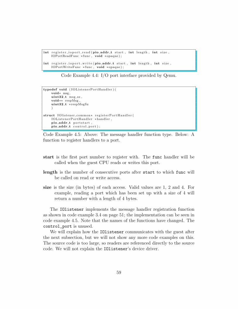
int r e g i s t e r i o p o r t r e a d (pio addr t s t a r t , int l ength , int s i z e ,IOPortReadFunc ∗ func , void ∗opaque ) ;
int r e g i s t e r i o p o r t w r i t e (pio addr t s t a r t , int l ength , int s i z e ,IOPortWriteFunc ∗ func , void ∗opaque ) ;
Code Example 4.4: I/O port interface provided by Qemu.
typedef void ( IOListenerPortHandler ) (void∗ msg ,uint32 t msg sz ,void∗∗ respMsg ,uint32 t ∗ respMsgSz)
struct IOlistener common ∗ r eg i s t e rPo r tHand l e r (IOListenerPortHandler ∗handler ,pio addr t por t s t a r t ,pio addr t c on t r o l p o r t ) ;
Code Example 4.5: Above: The message handler function type. Below: Afunction to register handlers to a port.
start is the first port number to register with. The func handler will becalled when the guest CPU reads or writes this port.
length is the number of consecutive ports after start to which func willbe called on read or write access.
size is the size (in bytes) of each access. Valid values are 1, 2 and 4. Forexample, reading a port which has been set up with a size of 4 willreturn a number with a length of 4 bytes.
The IOlistener implements the message handler registration functionas shown in code example 3.4 on page 51; the implementation can be seen incode example 4.5. Note that the names of the functions have changed. Thecontrol_port is unused.
We will explain how the IOlistener communicates with the guest afterthe next subsection, but we will not show any more code examples on this.The source code is too large, so readers are referenced directly to the sourcecode. We will not explain the IOlistener’s device driver.
59
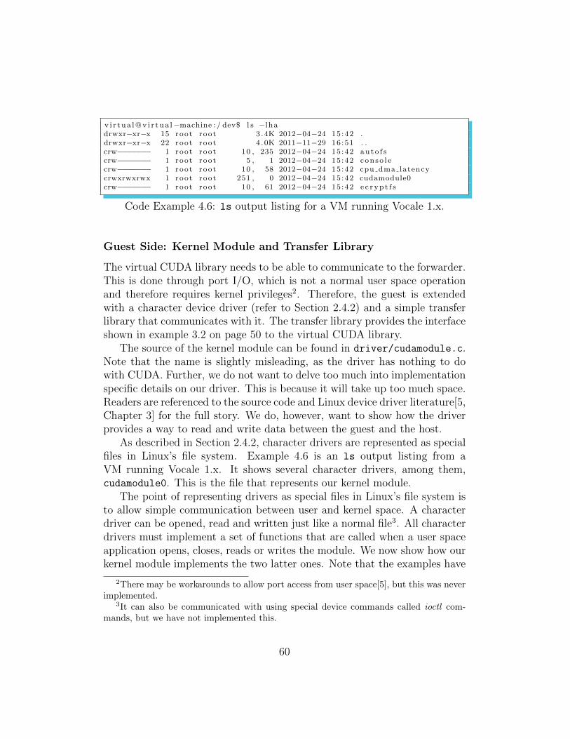
v i r tua l@v i r tua l−machine : / dev$ l s −lhadrwxr−xr−x 15 root root 3 .4K 2012−04−24 15 :42 .drwxr−xr−x 22 root root 4 .0K 2011−11−29 16 :51 . .crw−−−−−−− 1 root root 10 , 235 2012−04−24 15 :42 au to f scrw−−−−−−− 1 root root 5 , 1 2012−04−24 15 :42 conso l ecrw−−−−−−− 1 root root 10 , 58 2012−04−24 15 :42 cpu dma latencycrwxrwxrwx 1 root root 251 , 0 2012−04−24 15 :42 cudamodule0crw−−−−−−− 1 root root 10 , 61 2012−04−24 15 :42 e c r yp t f s
Code Example 4.6: ls output listing for a VM running Vocale 1.x.
Guest Side: Kernel Module and Transfer Library
The virtual CUDA library needs to be able to communicate to the forwarder.This is done through port I/O, which is not a normal user space operationand therefore requires kernel privileges2. Therefore, the guest is extendedwith a character device driver (refer to Section 2.4.2) and a simple transferlibrary that communicates with it. The transfer library provides the interfaceshown in example 3.2 on page 50 to the virtual CUDA library.
The source of the kernel module can be found in driver/cudamodule.c.Note that the name is slightly misleading, as the driver has nothing to dowith CUDA. Further, we do not want to delve too much into implementationspecific details on our driver. This is because it will take up too much space.Readers are referenced to the source code and Linux device driver literature[5,Chapter 3] for the full story. We do, however, want to show how the driverprovides a way to read and write data between the guest and the host.
As described in Section 2.4.2, character drivers are represented as specialfiles in Linux’s file system. Example 4.6 is an ls output listing from aVM running Vocale 1.x. It shows several character drivers, among them,cudamodule0. This is the file that represents our kernel module.
The point of representing drivers as special files in Linux’s file system isto allow simple communication between user and kernel space. A characterdriver can be opened, read and written just like a normal file3. All characterdrivers must implement a set of functions that are called when a user spaceapplication opens, closes, reads or writes the module. We now show how ourkernel module implements the two latter ones. Note that the examples have
2There may be workarounds to allow port access from user space[5], but this was neverimplemented.
3It can also be communicated with using special device commands called ioctl com-mands, but we have not implemented this.
60
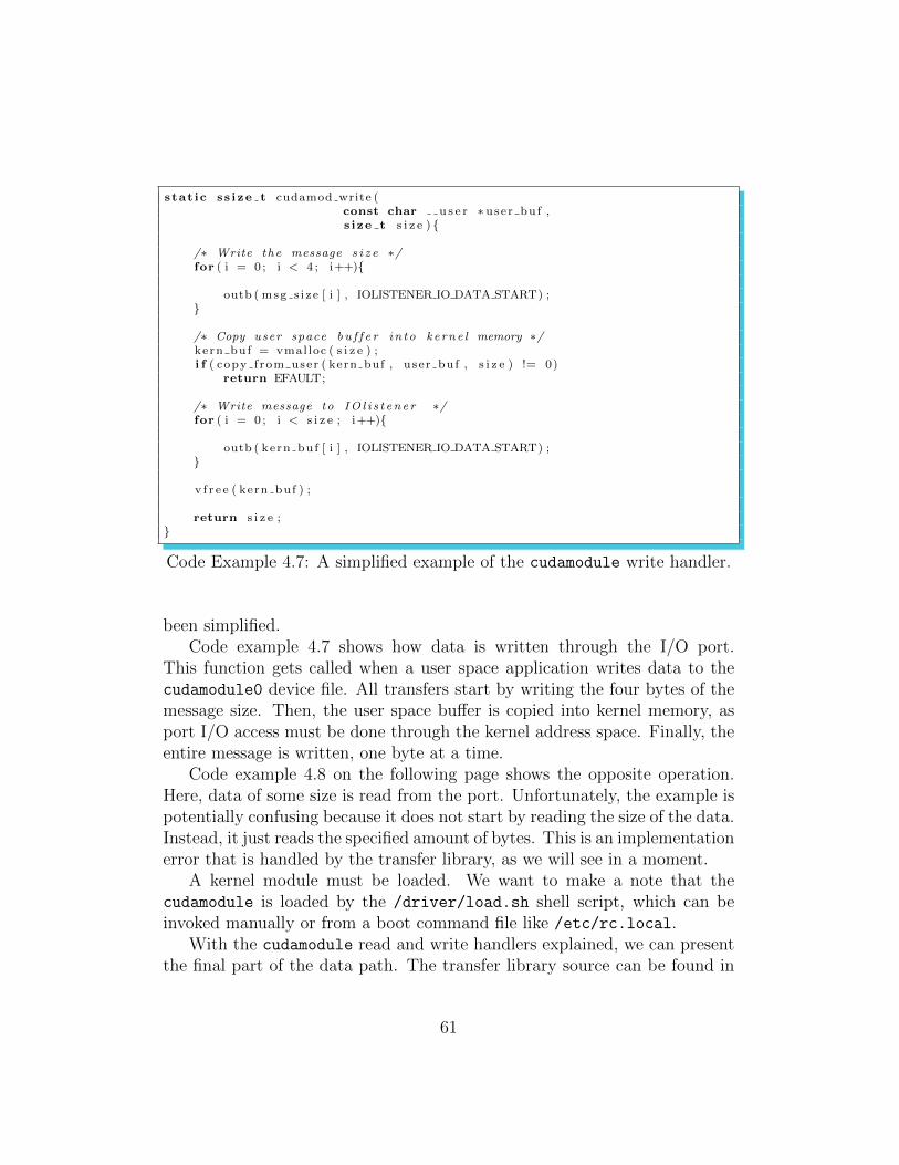
stat ic ss ize t cudamod write (const char u s e r ∗ user buf ,s ize t s i z e ) {
/∗ Write the message s i z e ∗/for ( i = 0 ; i < 4 ; i++){
outb ( msg s i z e [ i ] , IOLISTENER IO DATA START) ;}
/∗ Copy user space b u f f e r in to ke rne l memory ∗/kern buf = vmalloc ( s i z e ) ;i f ( copy f rom user ( kern buf , use r buf , s i z e ) != 0)
return EFAULT;
/∗ Write message to IO l i s t en e r ∗/for ( i = 0 ; i < s i z e ; i++){
outb ( kern buf [ i ] , IOLISTENER IO DATA START) ;}
v f r e e ( kern buf ) ;
return s i z e ;}
Code Example 4.7: A simplified example of the cudamodule write handler.
been simplified.Code example 4.7 shows how data is written through the I/O port.
This function gets called when a user space application writes data to thecudamodule0 device file. All transfers start by writing the four bytes of themessage size. Then, the user space buffer is copied into kernel memory, asport I/O access must be done through the kernel address space. Finally, theentire message is written, one byte at a time.
Code example 4.8 on the following page shows the opposite operation.Here, data of some size is read from the port. Unfortunately, the example ispotentially confusing because it does not start by reading the size of the data.Instead, it just reads the specified amount of bytes. This is an implementationerror that is handled by the transfer library, as we will see in a moment.
A kernel module must be loaded. We want to make a note that thecudamodule is loaded by the /driver/load.sh shell script, which can beinvoked manually or from a boot command file like /etc/rc.local.
With the cudamodule read and write handlers explained, we can presentthe final part of the data path. The transfer library source can be found in
61
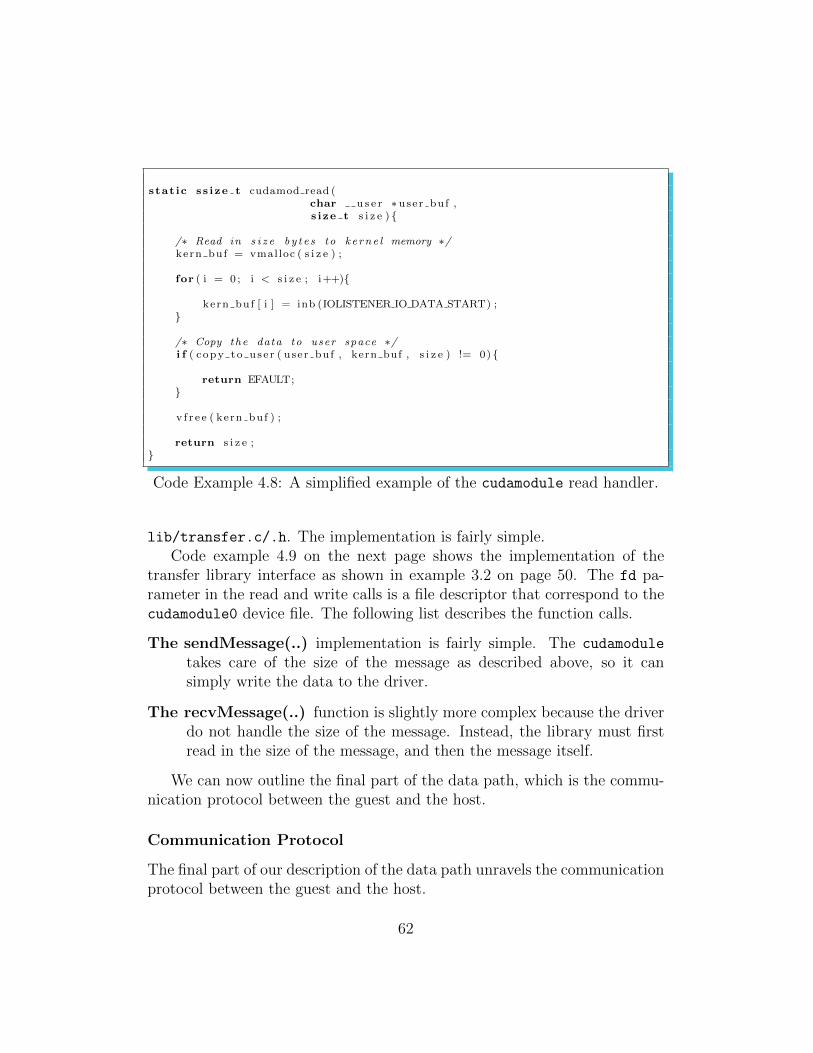
stat ic ss ize t cudamod read (char u s e r ∗ user buf ,s ize t s i z e ) {
/∗ Read in s i z e by t e s to ke rne l memory ∗/kern buf = vmalloc ( s i z e ) ;
for ( i = 0 ; i < s i z e ; i++){
kern buf [ i ] = inb (IOLISTENER IO DATA START) ;}
/∗ Copy the data to user space ∗/i f ( copy to us e r ( user buf , kern buf , s i z e ) != 0) {
return EFAULT;}
v f r e e ( kern buf ) ;
return s i z e ;}
Code Example 4.8: A simplified example of the cudamodule read handler.
lib/transfer.c/.h. The implementation is fairly simple.Code example 4.9 on the next page shows the implementation of the
transfer library interface as shown in example 3.2 on page 50. The fd pa-rameter in the read and write calls is a file descriptor that correspond to thecudamodule0 device file. The following list describes the function calls.
The sendMessage(..) implementation is fairly simple. The cudamodule
takes care of the size of the message as described above, so it cansimply write the data to the driver.
The recvMessage(..) function is slightly more complex because the driverdo not handle the size of the message. Instead, the library must firstread in the size of the message, and then the message itself.
We can now outline the final part of the data path, which is the commu-nication protocol between the guest and the host.
Communication Protocol
The final part of our description of the data path unravels the communicationprotocol between the guest and the host.
62
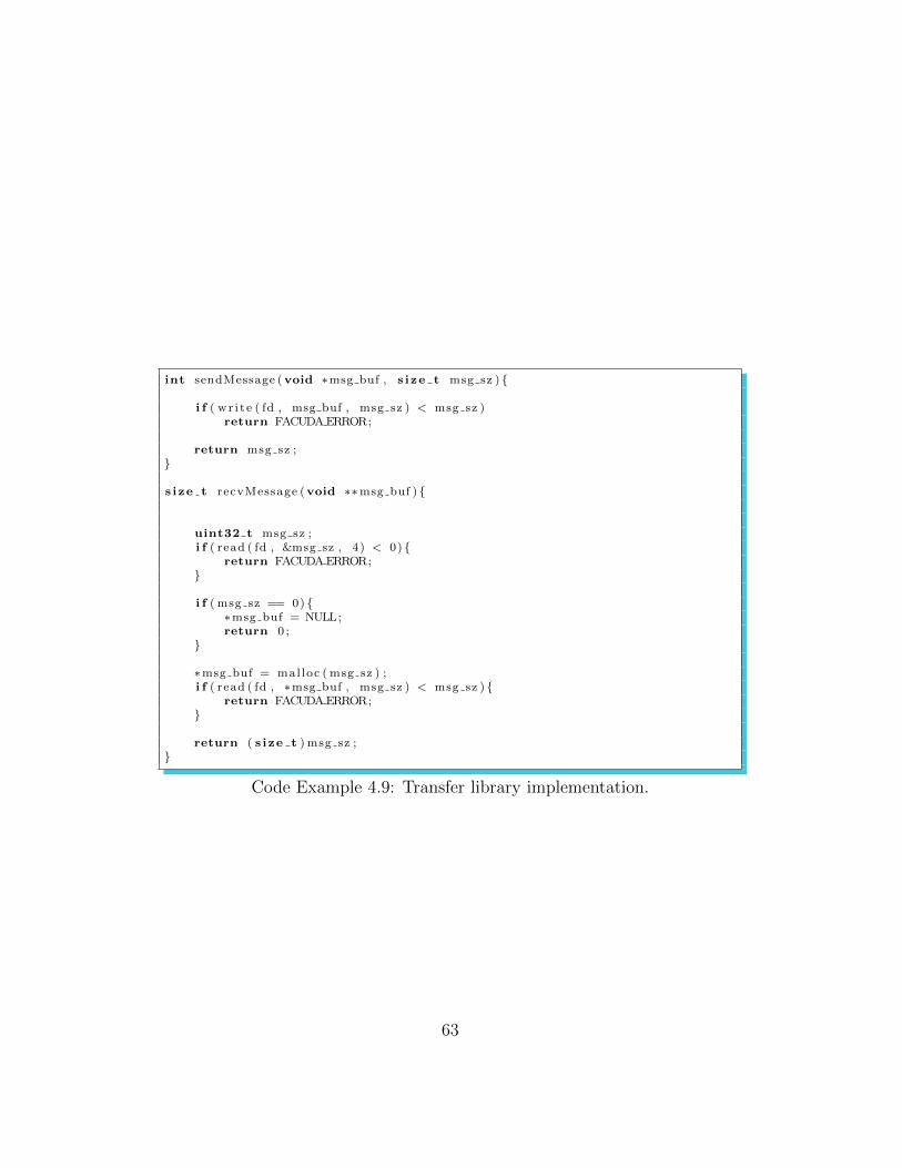
int sendMessage (void ∗msg buf , s ize t msg sz ) {
i f ( wr i t e ( fd , msg buf , msg sz ) < msg sz )return FACUDAERROR;
return msg sz ;}
s ize t recvMessage (void ∗∗msg buf ) {
uint32 t msg sz ;i f ( read ( fd , &msg sz , 4) < 0) {
return FACUDAERROR;}
i f ( msg sz == 0) {∗msg buf = NULL;return 0 ;
}
∗msg buf = mal loc ( msg sz ) ;i f ( read ( fd , ∗msg buf , msg sz ) < msg sz ) {
return FACUDAERROR;}
return ( s ize t ) msg sz ;}
Code Example 4.9: Transfer library implementation.
63
It is important to realize, as we have mentioned earlier, that all communi-cation must be initiated from the guest. Moreover, we do not support severalmessages ”in flight”; that is, when someone writes a message to the transferlibrary, they must also make the call to receive the response message beforeany other communication can take place.
The message protocol works as follows (we apologize for the lack of figures,there will be more illustrative examples later):
1. The transfer library gets a sendMessage(..) request with a pointer touser space data and a size.
2. The transfer library writes the buffer and size to the cudamodule devicefile.
3. The cudamodule writes the size of the message to the IOlistener, onebyte at a time.
4. The IOlistener receives the size. It allocates a buffer to hold themessage and prepares for the transfer.
5. The cudamodule starts writing the message, one byte at a time, to theIOlistener .
6. For each byte transferred, the IOlistener copies a byte to its messagebuffer from step 4.
7. When all the bytes of the message has been transferred, the IOlistenercalls the message handler function, if any.
8. When the message handler is complete, the IOlistener prepares toreturn the size of the response message. It can be 0.
9. The sendMessage(..) function from step 1 returns. The user of thetransfer library must now make to receive the response data.
10. The transfer library gets a recvMessage(..) request.
11. The transfer library reads four bytes from the cudamodule device file.
12. The cudamodule reads the four bytes from the I/O port. These bytescorrespond to the size of the response message.
64
13. The transfer library gets the size of the response in these four bytesand allocates a buffer to hold the response message.
14. The transfer library makes to read the message from the cudamodule
with the response size.
15. The cudamodule reads in the response message from the IOlistener,one byte at a time, and copies it to the transfer library.
16. The transfer library returns the message buffer to the calling user spaceapplication.
We have now explained how communication takes place between the guestand the host. Our next subsection will explain the implementation of the vir-tual CUDA library. We describe how it captures function calls and manageskernel launches.
4.2.2 Virtual CUDA Library
This subsection explains the implementation of the virtual CUDA library,which resides in the guest. This subsection is the most detailed in the thesis,as it represents a lot of low level work.
Applications in the guest should be able to use the virtual library ac-cording to the design goals in Section 3.2.2 on page 40. The reader shouldunderstand the main CUDA concepts described in Section 2.3.1 to fully ap-preciate all the points made in this subsection.
The virtual CUDA library source can be found in /lib/virtCudaLib.cpp.The library is easily compiled and installed by invoking make lib and sudo
make reinstall in this directory. This compiles, links and installs the li-brary as covered in Section 2.4.1.
Developers working in VMs should be able to invoke the CUDA tools,for example nvcc, as normal without any knowledge that they are using avirtual library. Since nvcc handles linking with the real CUDA library, itis necessary to ”fool” it into linking object code with the virtual library inaddition to the real one. Remember that we don’t want to override absolutelyeverything from the CUDA library, just the functionality that requires thepresence of a physical GPU (see the third paragraph of Section 3.3.1). Thereare two ways in which this can be done:
65
LIBRARIES =+ −l f akecuda −l cuda r t
Code Example 4.10: A snippet of the nvcc.profile file.
• Setting the LD PRELOAD environment variable. This can be usedto preload the virtual library in the linking phase, effectively overridingthe real one.
• Changing a special file, /usr/local/cuda/bin/nvcc.profile. Thisfile contains the library names that are used for linking of CUDA ap-plications. Example 4.10 shows a simplified snippet of the file and howit can be edited to override the standard library (lcudart is the reallibrary).
The latter is the one implemented by Vocale, as the first one should not beused as a permanent solution for overriding library functionality[29]. Whennvcc builds CUDA executables in the guest, it will first look for symbolreferences in the fakecuda library, which implements fake versions of therequired functions. Everything else is linked with the standard CUDA library,cudart.
The rest of the subsection explains how the virtual CUDA library imple-ments function calls, device memory transfers and kernel launches.
Function Call Forwarding
We will now outline how function calls are forwarded throughout Vocale’ssubsystems.
The following list illustrates the general algorithm for performing remoteprocedure calling from the guest (see Figure 4.3 on the next page):
1. A guest CUDA application calls a library function from the CUDA API,for example cudaGetDeviceCount(..). The virtual CUDA library in-tercepts the call. Its implementation of cudaGetDeviceCount(..) con-structs a call request message containing:
• A request type identifier. Always set to normal call.
• A call identifier for cudaGetDeviceCount(..).
• A data structure containing function input / output parameters.
66
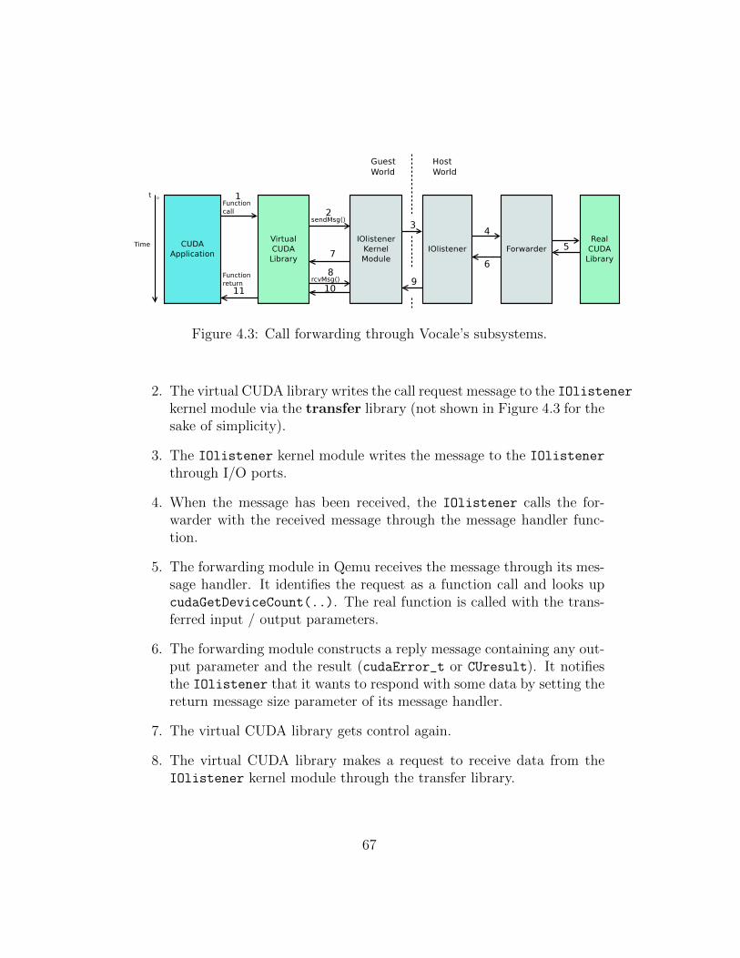
Figure 4.3: Call forwarding through Vocale’s subsystems.
2. The virtual CUDA library writes the call request message to the IOlistenerkernel module via the transfer library (not shown in Figure 4.3 for thesake of simplicity).
3. The IOlistener kernel module writes the message to the IOlistener
through I/O ports.
4. When the message has been received, the IOlistener calls the for-warder with the received message through the message handler func-tion.
5. The forwarding module in Qemu receives the message through its mes-sage handler. It identifies the request as a function call and looks upcudaGetDeviceCount(..). The real function is called with the trans-ferred input / output parameters.
6. The forwarding module constructs a reply message containing any out-put parameter and the result (cudaError_t or CUresult). It notifiesthe IOlistener that it wants to respond with some data by setting thereturn message size parameter of its message handler.
7. The virtual CUDA library gets control again.
8. The virtual CUDA library makes a request to receive data from theIOlistener kernel module through the transfer library.
67
9. The IOlistener kernel module reads I/O ports to fetch data from theIOlistener .
10. The virtual CUDA library gets the response message from the forward-ing module.
11. The cudaGetDeviceCount(..) function in the virtual CUDA libraryreturns any output parameters and the return type exactly accordingto the ”real” function.
The forwarding module is the last component of the system and is re-sponsible for executing CUDA function calls natively using the real CUDAlibrary. It is described in subsection 4.2.3.
Code example 4.11 on the following page shows the fake implementationof the cudaGetDeviceCount(..) CUDA API call.
Memory Transfers
The CUDA API provides many functions for handling memory transfers,the most basic being cudaMemcpy(..). A range of other functions handlevariations of 2 - and 3 - dimensional array data transfers as well. All of theminvolve source and destination pointers, as well as a property describing thedirection of the copy; see code example 4.12 on the next page.
kind specifies the direction of the transfer, a total of four directions betweenthe guest and device memory operating areas.
dst is the destination memory pointer. Whether it is a device or host pointerdepends on the direction of the copy.
src is the source memory pointer. Whether it is a device or host pointerdepends on the direction of the copy.
count specifies the number of bytes to transfer.
Our implementation of this function is fairly simple. Depending on thecopy direction, the data is transferred from the guest or device piggybackedon top of the request or response message (see Figure 4.4 on page 70). Thesize parameter of cudaMemcpy(..) is important to determine the size of the
68
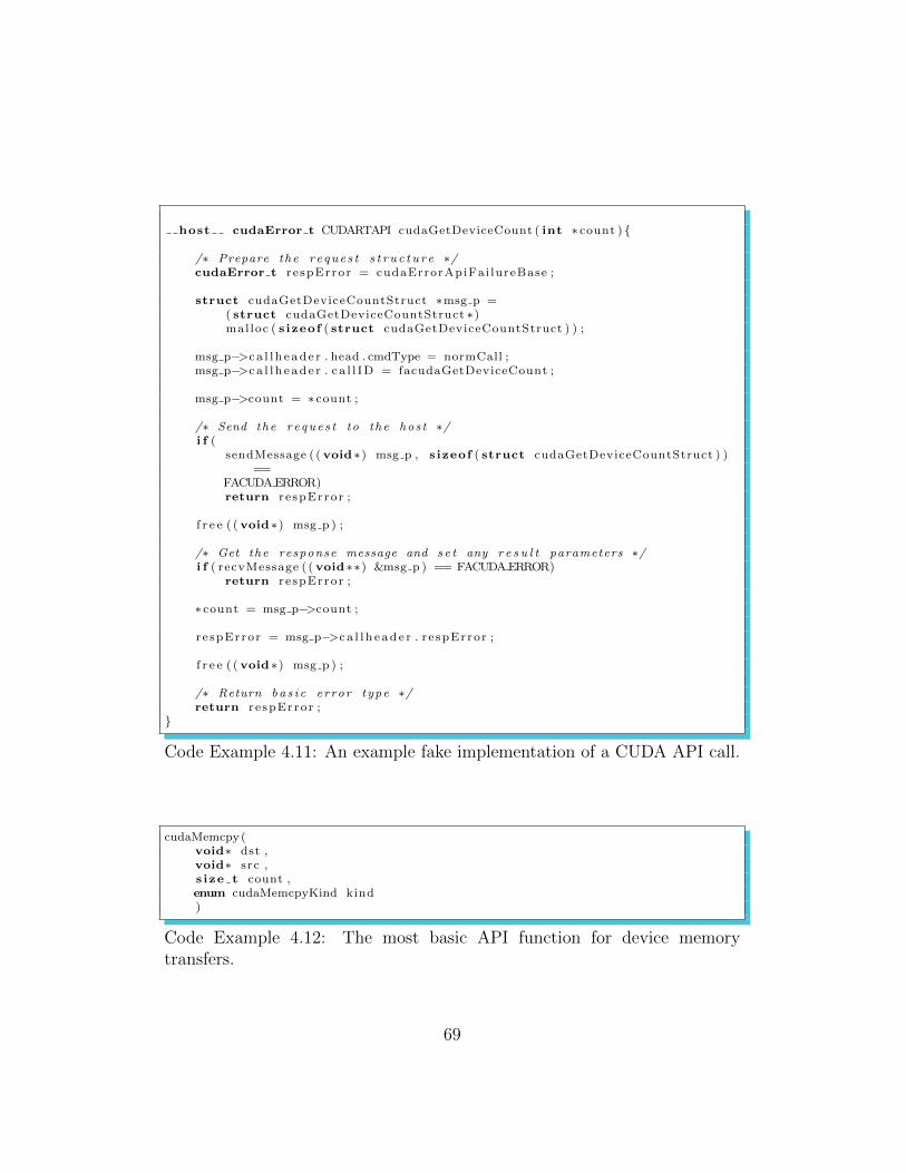
host cudaError t CUDARTAPI cudaGetDeviceCount ( int ∗ count ) {
/∗ Prepare the r eque s t s t r u c t u r e ∗/cudaError t r e spError = cudaErrorApiFai lureBase ;
struct cudaGetDeviceCountStruct ∗msg p =( struct cudaGetDeviceCountStruct ∗)mal loc ( s izeof ( struct cudaGetDeviceCountStruct ) ) ;
msg p−>c a l l h e ad e r . head . cmdType = normCall ;msg p−>c a l l h e ad e r . c a l l ID = facudaGetDeviceCount ;
msg p−>count = ∗ count ;
/∗ Send the reque s t to the hos t ∗/i f (
sendMessage ( ( void ∗) msg p , s izeof ( struct cudaGetDeviceCountStruct ) )==
FACUDAERROR)return r e spError ;
f r e e ( ( void ∗) msg p ) ;
/∗ Get the response message and s e t any r e s u l t parameters ∗/i f ( recvMessage ( ( void ∗∗) &msg p ) == FACUDAERROR)
return r e spError ;
∗ count = msg p−>count ;
r e spError = msg p−>c a l l h e ad e r . r e spError ;
f r e e ( ( void ∗) msg p ) ;
/∗ Return ba s i c error type ∗/return r e spError ;
}
Code Example 4.11: An example fake implementation of a CUDA API call.
cudaMemcpy(void∗ dst ,void∗ src ,s ize t count ,enum cudaMemcpyKind kind)
Code Example 4.12: The most basic API function for device memorytransfers.
69
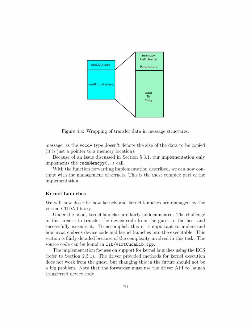
Figure 4.4: Wrapping of transfer data in message structures.
message, as the void* type doesn’t denote the size of the data to be copied(it is just a pointer to a memory location).
Because of an issue discussed in Section 5.3.1, our implementation onlyimplements the cudaMemcpy(..) call.
With the function forwarding implementation described, we can now con-tinue with the management of kernels. This is the most complex part of theimplementation.
Kernel Launches
We will now describe how kernels and kernel launches are managed by thevirtual CUDA library.
Under the hood, kernel launches are fairly undocumented. The challengein this area is to transfer the device code from the guest to the host andsuccessfully execute it. To accomplish this it is important to understandhow nvcc embeds device code and kernel launches into the executable. Thissection is fairly detailed because of the complexity involved in this task. Thesource code can be found in lib/virtCudaLib.cpp.
The implementation focuses on support for kernel launches using the ECS(refer to Section 2.3.1). The driver provided methods for kernel executiondoes not work from the guest, but changing this in the future should not bea big problem. Note that the forwarder must use the driver API to launchtransferred device code.
70
The main problem of kernel launches is that CUDA and nvcc does a greatjob at hiding:
• The low level details of embedding the device code in the executable.We need to extract this code, send it to the forwarder and register it.
• The launching of kernels. We need to know when kernel launches hap-pen so we can launch them at the correct time.
When a developer compiles a CUDA source file, nvcc takes care of compilingany device code to PTX or architecture specific code. This is embedded intothe executable and not visible to the developer. Internally, it also keeps trackof kernels so that they can be launched with the ECS.
The challenge here is the following:
• Find out how kernel launches are managed by nvcc.
• Find a way to handle compiled device code, so that it can be transferredto the host and executed.
Initial approaches was to use programs like readelf, objdump and nm
to attempt to reverse engineer CUDA object files and executables. Theseprograms make it possible to look at hidden functions, assembly code anddata sections. It showed that under the scene, the ECS is translated to aspecific set of functions: The CUDA runtime API functions for launchingkernels. This means that the ECS is just another way to invoke anothergroup of functions.
While this shows how kernel launches are handled, it provides no infor-mation on how the kernel code is embedded in the executable. Using thetools above to reverse engineer this is very time consuming, and in the end,nvcc itself gave us all the answers.
The simplest way to look at how nvcc compiles the ECS and manageskernel code is to use nvcc’s --cuda switch. This generates a .cu.c file thatcan be compiled and linked without any support from NVIDIA proprietarytools. It can be thought of as CUDA source files in open source C. Inspectionof this file verified how the ECS is managed, and showed how kernel codewas managed.
1. Device code is embedded as a fat binary object in the executable’s.rodata section. It has variable length depending on the kernel code.
71
2. For each kernel, a host function with the same name as the kernel isadded to the source code.
3. Before main(..) is called, a function called cudaRegisterAll(..) per-forms the following work:
• Calls a registration function, cudaRegisterFatBinary(..), witha void pointer to the fat binary data. This is where we can accessthe kernel code directly.
• For each kernel in the source file, a device function registrationfunction, cudaRegisterFunction(..), is called. With the list ofparameters is a pointer to the function mentioned in step 2.
4. As aforementioned, each ECS is replaced with the following functioncalls from the execution management category of the CUDA runtimeAPI.
• cudaConfigureCall(..) is called once to set up the launch con-figuration.
• The function from the second step is called. This calls anotherfunction, in which, cudaSetupArgument(..) is called once foreach kernel parameter. Then, cudaLaunch(..) launches the ker-nel with a pointer to the function from the second step.
5. An unregister function, cudaUnregisterBinaryUtil(..), is called witha handle to the fatbin data on program exit.
It seems that nvcc keeps track of kernels and kernel launches by reg-istering a list of function pointers (the second step in the list above). Allthe functions above are undocumented from NVIDIA’s part. The virtualCUDA library solves the problem of registering kernel code and tracking ker-nel launches by reimplementing each one of them, which we will get to in aminute.
There is still one problem to solve, which is the size of the fat binarydata object. This doesn’t seem to be provided anywhere. You are able tosee it in the source file, but not in the executable itself. We need this to beable to transfer the device code to the forwarder. A simple C program waswritten to look for elementary data types of variable sized, signed / unsigned
72
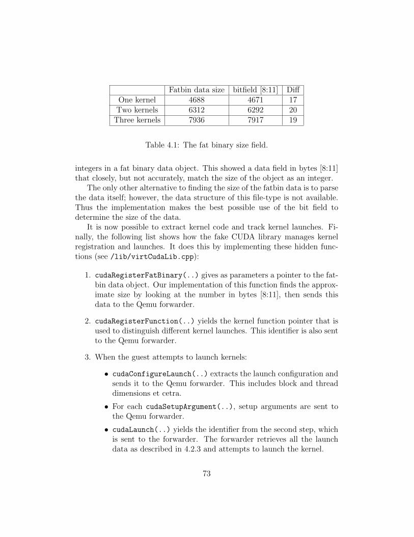
Fatbin data size bitfield [8:11] DiffOne kernel 4688 4671 17Two kernels 6312 6292 20
Three kernels 7936 7917 19
Table 4.1: The fat binary size field.
integers in a fat binary data object. This showed a data field in bytes [8:11]that closely, but not accurately, match the size of the object as an integer.
The only other alternative to finding the size of the fatbin data is to parsethe data itself; however, the data structure of this file-type is not available.Thus the implementation makes the best possible use of the bit field todetermine the size of the data.
It is now possible to extract kernel code and track kernel launches. Fi-nally, the following list shows how the fake CUDA library manages kernelregistration and launches. It does this by implementing these hidden func-tions (see /lib/virtCudaLib.cpp):
1. cudaRegisterFatBinary(..) gives as parameters a pointer to the fat-bin data object. Our implementation of this function finds the approx-imate size by looking at the number in bytes [8:11], then sends thisdata to the Qemu forwarder.
2. cudaRegisterFunction(..) yields the kernel function pointer that isused to distinguish different kernel launches. This identifier is also sentto the Qemu forwarder.
3. When the guest attempts to launch kernels:
• cudaConfigureLaunch(..) extracts the launch configuration andsends it to the Qemu forwarder. This includes block and threaddimensions et cetra.
• For each cudaSetupArgument(..), setup arguments are sent tothe Qemu forwarder.
• cudaLaunch(..) yields the identifier from the second step, whichis sent to the forwarder. The forwarder retrieves all the launchdata as described in 4.2.3 and attempts to launch the kernel.
73

Note that while configuring a kernel launch this way, the CUDA applica-tion may (and will) get interrupted and rescheduled at some stages. This isconsidered as a critical section in the program’s execution, as other CUDAapplications may also be attempting to launch kernels at that time. To ad-dress this, the forwarder associates launch configuration data with the callingguest Process Identifier (PID). The launch parameters are stored in linkedlists, and can be retrieved when the guest makes to launch a kernel.
Automatic Code Generation
Our concluding remark on the implementation of the virtual CUDA libraryregard the amount of work required to implement everything. There areapproximately 220 functions in the CUDA APIs, all of which require:
• An implementation in the virtual library for the guest.
• An implementation in the forwarding module in Qemu.
• Data structures for function call parameters and identifiers.
To address this problem we have developed a Python script that recur-sively parses the header files of the CUDA API for function declarations,starting with cuda.h and cuda runtime.h. The script can be found inpython/parseFunc.py.
When the script finds a function, the script generates the necessaryimplementation listed above in four separate files (fake functions.cpp,forwarding functions.cpp, callID.h and structs.h). These are placedin the python/autogen folder.
4.2.3 CUDA Forwarder
The final part of this section describes the forwarding module in Qemu. Thetask of this component is to forward function calls from VMs. The sourcecode can be reviewed in src/cudaforward.cu. Refer to the readme.pdf filementioned in Section 1.3 for a guide on adding .cu files to Qemu.
The forwarder registers a handler function with the IOlistener with themessage handler shown in code example 4.5 on page 59. A simplified look atthe implementation can be seen in code example 4.13 on the following page.
74
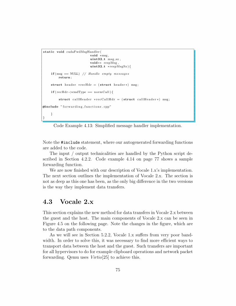
stat ic void cudaFwdMsgHandler (void ∗msg ,uint32 t msg sz ,void∗∗ respMsg ,uint32 t ∗ respMsgSz ) {
i f (msg == NULL) // Handle empty messagesreturn ;
struct header ∗ recHdr = ( struct header ∗) msg ;
i f ( recHdr−>cmdType == normCall ) {
struct ca l lHeader ∗ recCal lHdr = ( struct ca l lHeader ∗) msg ;
#include ” f o rwa rd ing func t i on s . cpp”
}}
Code Example 4.13: Simplified message handler implementation.
Note the #include statement, where our autogenerated forwarding functionsare added to the code.
The input / output technicalities are handled by the Python script de-scribed in Section 4.2.2. Code example 4.14 on page 77 shows a sampleforwarding function.
We are now finished with our description of Vocale 1.x’s implementation.The next section outlines the implementation of Vocale 2.x. The section isnot as deep as this one has been, as the only big difference in the two versionsis the way they implement data transfers.
4.3 Vocale 2.x
This section explains the new method for data transfers in Vocale 2.x betweenthe guest and the host. The main components of Vocale 2.x can be seen inFigure 4.5 on the following page. Note the changes in the figure, which areto the data path components.
As we will see in Section 5.2.2, Vocale 1.x suffers from very poor band-width. In order to solve this, it was necessary to find more efficient ways totransport data between the host and the guest. Such transfers are importantfor all hypervisors to do for example clipboard operations and network packetforwarding. Qemu uses Virtio[25] to achieve this.
75
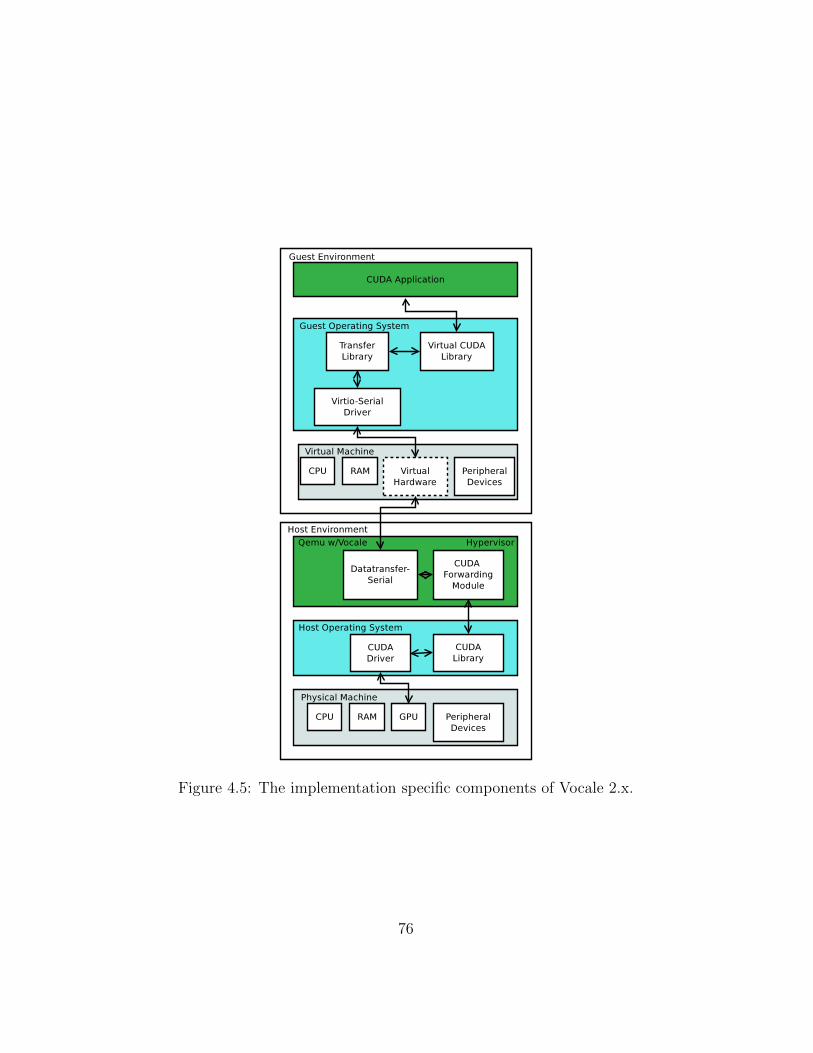
Figure 4.5: The implementation specific components of Vocale 2.x.
76
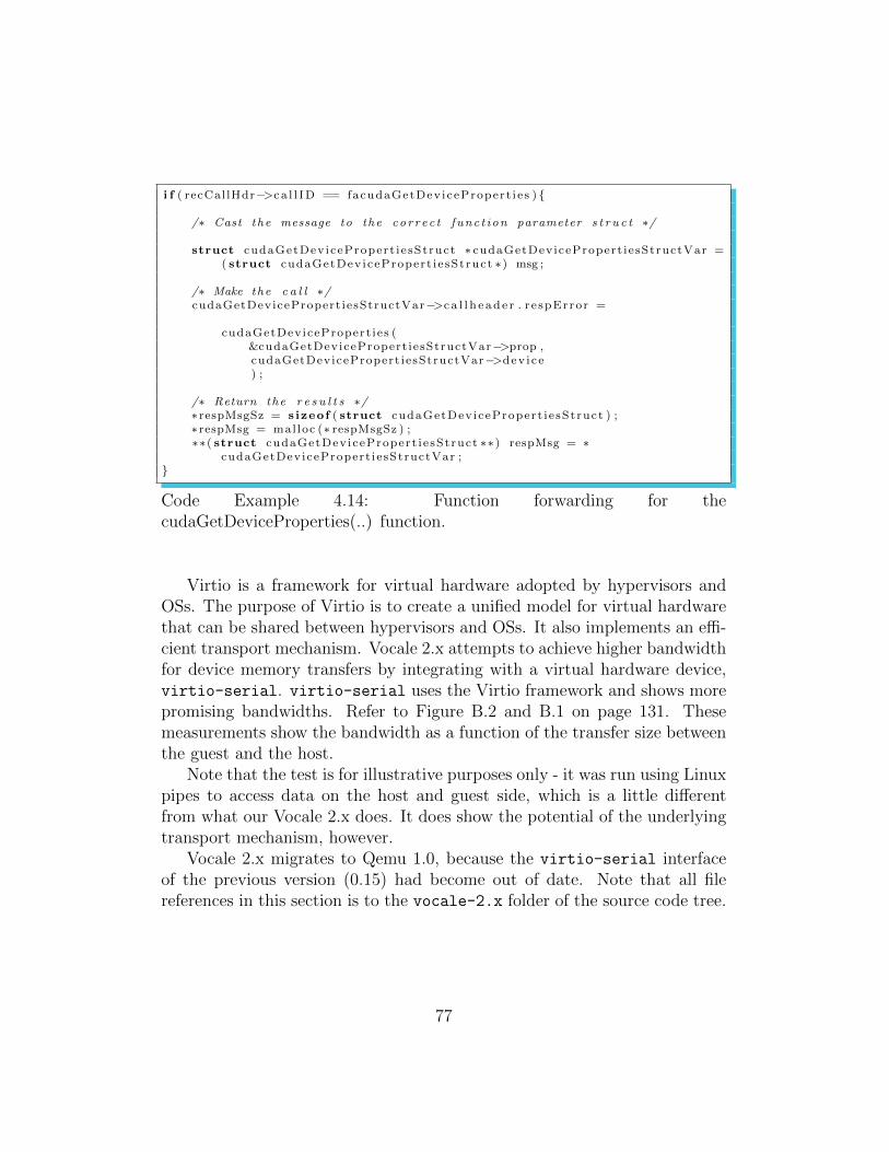
i f ( recCal lHdr−>ca l l ID == facudaGetDev icePropert i e s ) {
/∗ Cast the message to the co r r ec t func t i on parameter s t r u c t ∗/
struct cudaGetDev icePropert i e sStruct ∗ cudaGetDevicePropert iesStructVar =( struct cudaGetDev icePropert i e sStruct ∗) msg ;
/∗ Make the c a l l ∗/cudaGetDevicePropert iesStructVar−>c a l l h e ad e r . r e spError =
cudaGetDevicePropert ies (&cudaGetDevicePropert iesStructVar−>prop ,cudaGetDevicePropert iesStructVar−>dev i ce) ;
/∗ Return the r e s u l t s ∗/∗ respMsgSz = s izeof ( struct cudaGetDev icePropert i e sStruct ) ;∗ respMsg = mal loc (∗ respMsgSz ) ;∗∗( struct cudaGetDev icePropert i e sStruct ∗∗) respMsg = ∗
cudaGetDevicePropert iesStructVar ;}
Code Example 4.14: Function forwarding for thecudaGetDeviceProperties(..) function.
Virtio is a framework for virtual hardware adopted by hypervisors andOSs. The purpose of Virtio is to create a unified model for virtual hardwarethat can be shared between hypervisors and OSs. It also implements an effi-cient transport mechanism. Vocale 2.x attempts to achieve higher bandwidthfor device memory transfers by integrating with a virtual hardware device,virtio-serial. virtio-serial uses the Virtio framework and shows morepromising bandwidths. Refer to Figure B.2 and B.1 on page 131. Thesemeasurements show the bandwidth as a function of the transfer size betweenthe guest and the host.
Note that the test is for illustrative purposes only - it was run using Linuxpipes to access data on the host and guest side, which is a little differentfrom what our Vocale 2.x does. It does show the potential of the underlyingtransport mechanism, however.
Vocale 2.x migrates to Qemu 1.0, because the virtio-serial interfaceof the previous version (0.15) had become out of date. Note that all filereferences in this section is to the vocale-2.x folder of the source code tree.
77
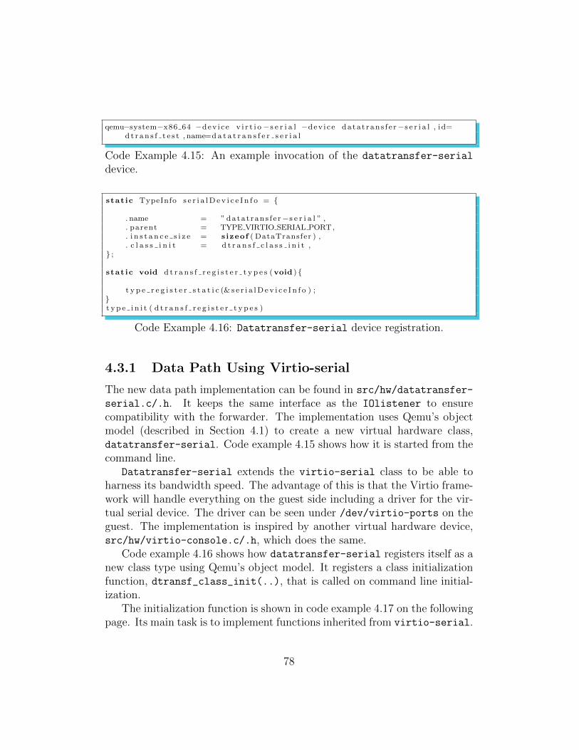
qemu−system−x86 64 −dev i ce v i r t i o−s e r i a l −dev i ce da ta t rans f e r−s e r i a l , id=d t r an s f t e s t , name=d a t a t r a n s f e r s e r i a l
Code Example 4.15: An example invocation of the datatransfer-serial
device.
stat ic TypeInfo s e r i a lD e v i c e I n f o = {
. name = ” data t ran s f e r−s e r i a l ” ,
. parent = TYPE VIRTIO SERIAL PORT,
. i n s t a n c e s i z e = s izeof ( DataTransfer ) ,
. c l a s s i n i t = d t r a n s f c l a s s i n i t ,} ;
stat ic void d t r a n s f r e g i s t e r t y p e s (void ) {
t y p e r e g i s t e r s t a t i c (& s e r i a lD e v i c e I n f o ) ;}t y p e i n i t ( d t r a n s f r e g i s t e r t y p e s )
Code Example 4.16: Datatransfer-serial device registration.
4.3.1 Data Path Using Virtio-serial
The new data path implementation can be found in src/hw/datatransfer-
serial.c/.h. It keeps the same interface as the IOlistener to ensurecompatibility with the forwarder. The implementation uses Qemu’s objectmodel (described in Section 4.1) to create a new virtual hardware class,datatransfer-serial. Code example 4.15 shows how it is started from thecommand line.
Datatransfer-serial extends the virtio-serial class to be able toharness its bandwidth speed. The advantage of this is that the Virtio frame-work will handle everything on the guest side including a driver for the vir-tual serial device. The driver can be seen under /dev/virtio-ports on theguest. The implementation is inspired by another virtual hardware device,src/hw/virtio-console.c/.h, which does the same.
Code example 4.16 shows how datatransfer-serial registers itself as anew class type using Qemu’s object model. It registers a class initializationfunction, dtransf_class_init(..), that is called on command line initial-ization.
The initialization function is shown in code example 4.17 on the followingpage. Its main task is to implement functions inherited from virtio-serial.
78
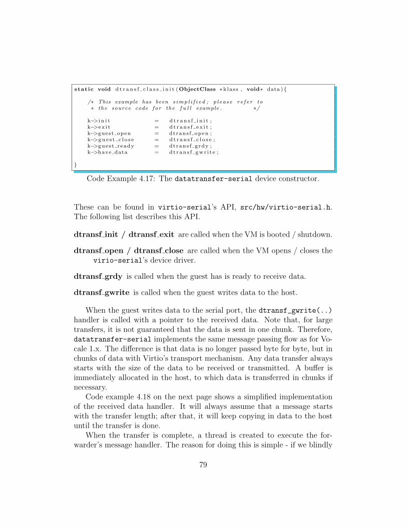
stat ic void d t r a n s f c l a s s i n i t (ObjectClass ∗ k la s s , void∗ data ) {
/∗ This example has been s imp l i f i e d ; p l ea s e r e f e r to∗ the source code fo r the f u l l example . ∗/
k−> i n i t = d t r a n s f i n i t ;k−>e x i t = d t r a n s f e x i t ;k−>guest open = dtrans f open ;k−>gu e s t c l o s e = d t r a n s f c l o s e ;k−>gues t r eady = dt ran s f g rdy ;k−>have data = d t r an s f gw r i t e ;
}
Code Example 4.17: The datatransfer-serial device constructor.
These can be found in virtio-serial’s API, src/hw/virtio-serial.h.The following list describes this API.
dtransf init / dtransf exit are called when the VM is booted / shutdown.
dtransf open / dtransf close are called when the VM opens / closes thevirio-serial’s device driver.
dtransf grdy is called when the guest has is ready to receive data.
dtransf gwrite is called when the guest writes data to the host.
When the guest writes data to the serial port, the dtransf_gwrite(..)
handler is called with a pointer to the received data. Note that, for largetransfers, it is not guaranteed that the data is sent in one chunk. Therefore,datatransfer-serial implements the same message passing flow as for Vo-cale 1.x. The difference is that data is no longer passed byte for byte, but inchunks of data with Virtio’s transport mechanism. Any data transfer alwaysstarts with the size of the data to be received or transmitted. A buffer isimmediately allocated in the host, to which data is transferred in chunks ifnecessary.
Code example 4.18 on the next page shows a simplified implementationof the received data handler. It will always assume that a message startswith the transfer length; after that, it will keep copying in data to the hostuntil the transfer is done.
When the transfer is complete, a thread is created to execute the for-warder’s message handler. The reason for doing this is simple - if we blindly
79

stat ic ss ize t d t r an s f gw r i t e (const uint8 t ∗buf ,s ize t l en ) {
/∗ I s t h i s the s t a r t o f a new message? ∗/
/∗ I f so , i n i t i a t e a new t r an s f e r . A l l o ca t e data∗ and s e t the s i z e o f the t r an s f e r . ∗/
i f ( t r an s fS ta t e−>t r a n s f S i z e == 0) {
uint32 t t r a n s f e r S i z e = ∗ ( ( uint32 t ∗) buf ) ;
t r an s fS ta t e−>t r a n s f S i z e = t r a n s f e r S i z e ;t r an s fS ta t e−>data = mal loc ( t r a n s f e r S i z e ) ;t r an s fS ta t e−>t rans fRece ived = 0 ;
}/∗ I f not , cont inue reading in data . ∗/else {
for ( i = 0 ; i < l en ; i++){t r an s fS ta t e−>data [ t r an s fS ta t e−>t rans fRece ived + i ] = buf [ i ] ;
}t r an s fS ta t e−>t rans fRece ived += len ;
/∗ Are we done? I f so , c a l l message handler . ∗/i f ( t r an s fS ta t e−>t rans fRece ived == tran s fS ta t e−>t r a n s f S i z e ) {
struct r ep l y th r e ad a rg s ∗ r ep l ya r g s =mal loc ( s izeof ( struct r ep l y th r e ad a rg s ) ) ;
r ep lyarg s−>port = port ;r ep lyarg s−>buf = ( const uint8 t ∗) t r an s fS ta t e−>data ;r ep lyarg s−>l en = t ran s fS ta t e−>t r a n s f S i z e ;
t r an s fS ta t e−>t r a n s f S i z e = 0 ;t r an s fS ta t e−>t rans fRece ived = 0 ;
p th r ead c r ea t e (&rep lythread ,&r t a t t r s ,th read rep ly ,(void ∗) r ep l ya r g s ) ;
}}return l en ;
}
Code Example 4.18: The datatransfer-serial received data routine.
80

called the message handler from this function, we can risk that the callingguest application never returns to read in the response. The message cyclethus never completes.
The thread implementation can be seen in code example 4.19 on thefollowing page. The thread takes care of calling the forwarder’s messagehandler, and sends the response message, if any, back to the guest.
The changes require some minor changes to the transfer library. Theseare reflected in lib/transfer-virtio-serial.c and are not covered here.
4.3.2 Changes to the CUDA Forwarder
During testing of Vocale 2.x it became evident that there was a new problemwith the implementation. While function calls were forwarded and executedas normal, it seemed that writing data to device memory using functions likecudaMemset(..) had no verifiable effect.
The problem was related to CUDA contexts. We have described these inSection 2.3.1 as a form of software virtual memory solution: Device memorypointers allocated in one CUDA context have no meaning, and cannot beused, in another. What happened with Vocale 2.x was that, as reply threadsreturned, the context of that thread was lost. So was any device memorypointers allocated in any previous reply threads. This was an unforeseenissue that should have been part of the design.
A trivial patch was made to the forwarder to accommodate this issue (thechanges are reflected in src/cudaforward.cu). The temporary solution isfor the forwarder to have a single thread going at all times that handles anyremote call execution. The message handler simply passes the call to thethread and waits for it to complete.
This ensures that contexts are not lost, but creates new problems: Thesolution is a serious security threat in that all guest CUDA applications nowshare the same context. We describe this issue in detail in Section 5.3.1.
In this chapter we have seen how Vocale is implemented. In the next, wewill see how well the different iterations of Vocale work when compared to areal CUDA library. We will discuss our implementation and evaluate Vocalefrom a performance critical view.
81

stat ic void∗ th r ead r ep l y (void∗ args ) {
/∗ Cal l the data handler ∗/datahandler (
r ep lyarg s−>buf ,r ep lyarg s−>len ,&respMsg ,&respMsgSz ) ;
/∗ Write the response message s i z e ∗/s i z e = v i r t i o s e r i a l w r i t e (
r ep lyarg s−>port ,( const uint8 t ∗)&respMsgSz ,4) ;
/∗ Do we have response data? ∗/i f ( respMsgSz != 0) {
/∗ Keep t r an s f e r r i n g u n t i l we are done ∗/while ( toSend != 0) {
while ( v i r t i o s e r i a l g u e s t r e a d y ( rep lyarg s−>port ) == 0) ;ju s tSent = v i r t i o s e r i a l w r i t e (
r ep lyarg s−>port ,( ( uint8 t ∗) respMsg ) + sent ,toSend ) ;
toSend −= jus tSent ;sent += jus tSent ;
}f r e e ( respMsg ) ;
}
f r e e ( ( void ∗) r ep lyargs−>buf ) ;f r e e ( args ) ;
p th r ead ex i t (NULL) ;}
Code Example 4.19: The datatransfer-serial message callback function.
82
Chapter 5
Discussion and Results
This chapter evaluates the implementation and performance of Vocale. Bydoing this we want to find out if there are any particular challenges involvedin implementing GPU acceleration for applications in VMs. We will also seewhat demands Vocale places on the hypervisor, and if the hypervisor cansatisfy them. We will use the term host or native performance when talkingabout the performance of the real CUDA library.
The chapter layout is as follows. The first section explains how we haveevaluated Vocale. We describe the programs we have run to verify thatfunction calls, device memory transfers and kernel launches are working. Wealso argument for and describe the performance tests that we have subjectedVocale to.
The second section evaluates the performance of Vocale. We look at howwell Vocale 1.x and 2.x works when compared to the performance of the realCUDA library.
The third and final section outlines our evaluation of Vocale. We look athow well our implementation of Vocale works in practice and describe thechallenges and issues we have met during development and testing.
The performance tests can be found under the performance tests/ folderof the project source tree. All references to code in this chapter are to thisdirectory.
83
5.1 Evaluating Vocale
To answer the goals of the thesis we need to find out how well the imple-mentation of Vocale works and how efficient it is when compared to a realCUDA library. We also want to argue that our implementation is workingcorrectly. In this section we describe how this has been done and the varioustests we have implemented and run to assess the performance of Vocale.
We now explain how we can be certain that Vocale is indeed working.
5.1.1 Result Verification
In order to verify that the implementation works correctly, we have usedNVIDIA’s SDK examples to test CUDA API calls, kernel launches and devicememory transfers. Note that we have not tested the entire API, as theobjective of Vocale is not to create a perfect system, but rather study itsperformance impact and challenges. Stream related functions, for example,are not working (as we will discuss in Section 5.3.1). The following listdescribes the CUDA SDK example programs we have run on the guest toassess Vocale’s correctness.
• deviceQuery. This is a small program that queries all GPUs installedon the system for various properties such as the number of CUDA cores,amount of global / shared memory et cetra.
This has been verified working by comparing the output of the programfrom the guest with the output of the program from the native CUDAlibrary on the host.
• vectorAdd. Sample CUDA program that shows how vector addi-tion can be run on the GPU. It launches a kernel and performs devicememory transfers between the host and device to do this. To verifythe results, it uses the CPU to do the same vector addition, and crosschecks the CPU results with those of the GPU.
It has been verified working on the guest.
• bandwidthTest. This program can perform a range of functions toprofile the bandwidth between the host and the guest. It uses theCUDA event API to measure the time it takes to perform memorytransfers in all directions.
84
All the programs above have been tested and verified in both test beds(refer to Appendix A).
The virtual library also always returns the standard CUDA error codereceived from the forwarder, so the calling guest application will always knowif something went wrong. The exception is if an error occurs that preventsthe error code from being set (in other words, for some reason the call hasnot been executed by the forwarder). As an extra security, the error codeis initialized with ”unknown error” codes from the CUDA library to addressthis issue (see code example 4.11 on page 69):
• CUDA ERROR UNKNOWN is the CUDA driver API code forerrors that are unknown to the CUDA framework.
• cudaErrorApiFailureBase distinguishes the same error as above,but for the CUDA runtime API.
One could of course create a new error code not implemented by CUDAinstead of using these, but some support functions rely on them for correctoperation. An example is the cudaGetErrorString(error_code).
5.1.2 Performance Metrics
A virtual system should always provide at least the performance providedby its real counterpart. For Vocale, this is not possible, because all of Vo-cale’s functionality is supported by its real counterpart. This means that forany function call, kernel launch or device memory transfer, the performanceof that function is affected by the extra overhead incurred to execute thereal counterpart of that function. Thus Vocale should provide near nativeperformance instead, that is, minimize the execution overhead.
Therefore, our performance measurements should attempt to illustratethe extra overhead incurred for the range of functionality implemented byVocale. We will compare Vocale’s performance with the real CUDA libraryon the host, using the following performance metrics.
Inter / intra device bandwidth. We want to see the bandwidth to andfrom the device, as well as internally between memory regions in thedevice. There are examples of multi-core architectures that have failedsimply because the bandwidth to, from or internally in the device istoo slow.
85
Call execution delay. The time it takes from the execution of a particularAPI function until it returns.
Kernel Execution Delay. The time it takes from a kernel is executed tothe time it is finished doing its work. This type of execution is slightlydifferent from the call execution delay described above, because of theway Vocale manages fatbin data objects and launches kernels.
All the points above addresses various metrics that we will need to com-pare the performance of the virtual library with the real. The next subsectiondescribes the performance tests we have developed to measure them.
5.1.3 Performance Tests
To be able to perform the measurements listed above, a number of Pythonscripts and C programs have been developed. Some of them are based onthe bandwidthTest SDK example program described in Section 5.1.1. Thissubsection serves as documentation on how the tests are implemented andrun.
A convenience script, runTests.py, has been made for the purpose offurther work. It can be used to run the tests presented in this thesis on newhardware, or invoke them with different parameters. The script automaticallyanalyses the results and creates plots. More information can be found byinvoking the --help switch.
Device Bandwidth Measurement
This test can be found in bandwidth measurement/runTest.py. Measuringdevice bandwidth is accomplished by the means of the bandwidthTest SDKexample. The tests presented here perform device memory transfers in alldirections, with transfer sizes up to 200 MB.
The bandwidthTest program usually works by invoking data transfers ina range; from start to end with a specific increment.
. / bandwidthTest −−dev i ce=0 −−mode=range−−s t a r t=1 −−end=200000000 −−increment=4096
When testing device transfers up to 200 MB, however, this approach canbe impractical when the increment value is low. Because of this, the band-width measurement test invokes transfers on a transfers per decade basis.
86
For example, it can run 10 transfers per decade, meaning that in the transferrange 1 - 10, it will invoke transfer sizes {1, 2, ..., 9, 10}. This cuts the timerequired to perform the tests, and gives us a view of the whole transfer rangeat the same time.
Our measurements show the average bandwidth as a function of the trans-fer size. All tests have been run with 100 increments per decade, and 10 runsper transfer size.
Call Delay Measurement
The purpose of this test is to measure the time it takes from API calls are exe-cuted until they return. The measurement script is found in call overhead/
runtest.py. The test itself uses the CUDA API and is implemented as anormal CUDA program; see call overhead/call overhead.cu.
The CUDA test program uses a CPU timer to measure the time it takesbetween the execution of specific functions and kernels and the completion(return) of these operations. To ensure that the tests proceed without error,all tests are wrapped in C macros that perform error checking as well as timemeasurement.
The tests show the average execution delay on a set of CUDA API func-tion calls. Each call has been executed 100 times for each test.
Virtual GPU versus Virtual CPU
The last of our performance metrics, the kernel execution delay, is measuredwith this test. During development and testing, however, we saw that it alsogave a nice picture of Vocale as a whole. Therefore its usage is extended toalso measure the efficiency of our virtual GPU contra the CPU.
Note that, in spite of the name, the purpose of the test is not to see whicharchitecture can finish first. The purpose is to see how long time various stepsin the Discrete Cosine Transform (DCT) algorithm takes, in a way that wecan compare between a CPU and an GPU.
In this test, both the CPU and the GPU perform the DCT algorithm ofrandomly generated ”image” frames of different sizes. The DCT is one ofseveral stages involved in image compression. For example, an image framecan be split into 8x8 matrices of pixels. The DCT’s purpose is to attemptto aggregate image information into the corner of the matrix so that its sizecan be reduced.
87

Following is the formula to calculate the DCT of an 8x8 pixel block. Theexample is taken from the INF5063 course lecture on image compression[12]1.
Gu,v = α(u)α(v)7∑
x=0
7∑y=0
(gx,y − 128) cos[π∗u8
(x+ 1
2
)]cos[π∗v8
(y + 1
2
)]• u ∈
[0, 7]
, v ∈[0, 7]
, x ∈[0, 7]
, y ∈[0, 7]
• Gu,v is the output value at location (u, v) in the current 8x8 matrix.
• α(i) is a normalization function.
α(i) = {
√18
i = 0√28
otherwise
• gx,y is the input pixel value at position (x,y) in the current 8x8 matrix.
The calculation can be split into five stages. The test measures the in-dividual time it takes to perform these, which we will now explain. For aninput frame of m 8x8 blocks in the x direction, and n 8x8 blocks in the ydirection:
Calculating a cosine lookup table. The cosine product can be viewed asa lookup table of 4096 entries, as it is determined by x, y, u and v, allof which range from 0 to 7.
Calculating a normalization table. The normalization product α(u)α(v)can be viewed as a lookup table of 64 entries.
Matrix operations. For each 8x8 matrix in the input frame:
Normalization. Each pixel value in the current 8x8 matrix is normal-ized by subtracting 128 from it.
Summation and Multiplication. For each output pixel in the cur-rent 8x8 matrix, the two inner loop sums with multiplication inthe cosine lookup table are performed.
1The subtraction in (gx,y − 128) is not a part of the DCT, but we include it to getmore work for our test.
88
Output normalization. For each output pixel in the current 8x8 ma-trix, the loop sum from the previous step is multiplied with itscorresponding value in the normalization table.
All the results of the DCT transformation are verified with a softwarelibrary called FFTW[15]. The source code builds on the execution delaymeasurement test, and uses the same macros to perform error checking.
The test script can be found under cpugpu measurement/runtest.py,and the source can be seen in the same folder under cpuVSgpu.cu. Themeasurements show the average execution delay of the steps involved in theDCT as a function of input matrix size. The tests have been run 100 timesfor each matrix size.
This was our concluding remark on how we evaluate Vocale. The nextsubsection will discuss the performance of the real CUDA library as it standson the host, as well as Vocale 1.x and 2.x.
5.2 Performance Evaluation
In this section we study the performance of the real, non - virtualized CUDAlibrary contra the performance of Vocale. The tests have been run in twodifferent test beds, on three different GPUs (refer to Appendix A). Keep inmind that the GTX 280 and NVS 295 GPUs are installed on the same system.
5.2.1 Native Performance
This subsection presents the native performance results of the real CUDAlibrary; that is, the CUDA library as delivered by NVIDIA running directlyon the host. It is the same host that runs the guest. In this subsectionwe explain the behaviour of the graphs to the degree it is possible to get apicture of the natural properties of CUDA.
We will reference back to this subsection when we analyse the performanceof Vocale.
Call Overhead
The call overhead measurements can be found in Figure 5.1 on the followingpage. Note that the y-scale is logarithmic in this example to get a betterview of the measurements.
89
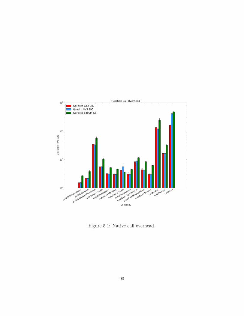
cudaGetDeviceCount
cudaGetDevice
cudaGetDeviceProperties
cudaStreamCreate
cudaStreamQuery
cudaStreamDestroy
cudaEventCreate
cudaEventRecord
cudaEventSynchronize
cudaEventElapsedTime
cudaEventDestroy
cudaMalloc
cudaMemset
cudaFree
Function ID
100
101
102
103
Exec
utio
n Ti
me
[us]
Function Call Overhead
GeForce GTX 280Quadro NVS 295GeForce 8400M GS
Figure 5.1: Native call overhead.
90
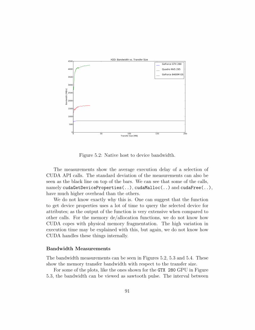
0 50 100 150 200Transfer Size [MB]
0
500
1000
1500
2000
2500
3000
3500
4000
4500
Band
wid
th [M
B/s]
H2D: Bandwidth vs. Transfer Size
GeForce GTX 280
Quadro NVS 295
GeForce 8400M GS
Figure 5.2: Native host to device bandwidth.
The measurements show the average execution delay of a selection ofCUDA API calls. The standard deviation of the measurements can also beseen as the black line on top of the bars. We can see that some of the calls,namely cudaGetDeviceProperties(..), cudaMalloc(..) and cudaFree(..),have much higher overhead than the others.
We do not know exactly why this is. One can suggest that the functionto get device properties uses a lot of time to query the selected device forattributes; as the output of the function is very extensive when compared toother calls. For the memory de/allocation functions, we do not know howCUDA copes with physical memory fragmentation. The high variation inexecution time may be explained with this, but again, we do not know howCUDA handles these things internally.
Bandwidth Measurements
The bandwidth measurements can be seen in Figures 5.2, 5.3 and 5.4. Theseshow the memory transfer bandwidth with respect to the transfer size.
For some of the plots, like the ones shown for the GTX 280 GPU in Figure5.3, the bandwidth can be viewed as sawtooth pulse. The interval between
91
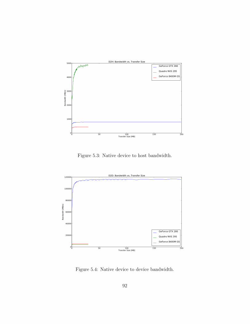
0 50 100 150 200Transfer Size [MB]
0
1000
2000
3000
4000
5000Ba
ndw
idth
[MB/
s]D2H: Bandwidth vs. Transfer Size
GeForce GTX 280
Quadro NVS 295
GeForce 8400M GS
Figure 5.3: Native device to host bandwidth.
0 50 100 150 200Transfer Size [MB]
0
20000
40000
60000
80000
100000
120000
Band
wid
th [M
B/s]
D2D: Bandwidth vs. Transfer Size
GeForce GTX 280
Quadro NVS 295
GeForce 8400M GS
Figure 5.4: Native device to device bandwidth.
92

the teeth is more dense for lower transfer sizes. The reason for this propertyis that the test is run with some number x transfer sizes per decade (asdescribed in the previous section) - in other words, the density of the transfersize measurements decreases as the transfer size increases.
Note that for two of the GPUs, the tests seem to stop at around 30 MB.This can be explained if we look at the measurements in Figure 5.4. For thisparticular transfer size, the test attempts to allocate 2 ∗ 30MB of devicememory to transfer a 30 MB memory block internally in the device. Thus themaximum transfer size of two of the GPUs, the NVS295 and the GF 8400M,is around 60 MB.
This is strange, as both GPUs have, respectively, 128 and 255 MB memory(refer to Appendix A). The GTX 280, however, can run the tests with transfersizes up to its full amount of memory, 1024 MB1. Our explanation for thisis that GPUs that are rendering the display output, which is the case forthe NVS 295 and GF 8400M, reserve space in device memory that leaves onlyaround 60 MB for CUDA operations.
Our final note on the bandwidth measurements are about the differencesin bandwidth for the GPUs. For example, for the device to device mea-surements in Figure 5.4, it is observed that the GTX 280 GPU excels whencompared to the others. This huge difference can be explained by the numberof CUDA cores (SMs) on each card.
The GTX 280 has 240 cores, the GF 8400M has 16 and the NVS 295 has8. It makes sense that the differences in bandwidth can be explained bythe number of cores, as the GPUs are tied for 1st, 2nd and 3rd place per-formance wise, respectively. This suggests that the CUDA library or driversomehow uses its SMs to perform copies, for example by executing memorycopy kernels.
For the bandwidth measurements between host and device, there are alsovariations in bandwidth for the different GPUs. We consider this dependenton the system configuration for our two test beds.
CPU versus GPU measurements
The CPU versus GPU measurements can be seen in Figures 5.5 and 5.6.Figure 5.5 shows the cumulative time taken to perform the DCT trans-
formation, while Figure 5.6 shows a more detailed plot of the time taken to
1The tests have been run with a transfer size of up to 200 MB to be able to more easilysee the measurements of the other GPUs.
93
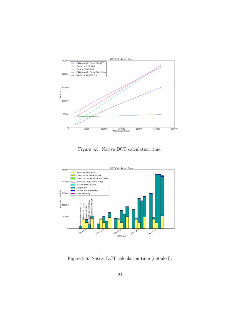
0 50000 100000 150000 200000 250000 300000Matrix Size [Pixels]
0
50000
100000
150000
200000
250000Ti
me
[us]
DCT Calculation Time
CPU Intel(R) Core(TM) i7 CGeForce GTX 280Quadro NVS 295CPU Intel(R) Core(TM)2 DuoGeForce 8400M GS
Figure 5.5: Native DCT calculation time.
128 x 128
256 x 128
256 x 256
512 x 256
512 x 512
Matrix Size
0
50000
100000
150000
200000
250000
Exec
utio
n Ti
me
[us]
CPU
Inte
l(R) C
ore(
TM) i
7 C
GeFo
rce
GTX
280
Quad
ro N
VS 2
95CP
U In
tel(R
) Cor
e(TM
)2 D
uoGe
Forc
e 84
00M
GS
DCT Calculation Time
Memory AllocationConstruct Cosine TableConstruct Normalization TableMemory Copy (GPU only)Matrix SubtractionLoop SumMatrix NormalizationFree Memory
Figure 5.6: Native DCT calculation time (detailed).
94
perform various stages of the DCT. The time varies with the size of the inputmatrix. From top to bottom, the legend in Figure 5.6 shows the steps takenby the GPU and CPU, in sequence, to finish the DCT.
Figure 5.5 shows us that of all the GPUs, the GTX 280 is the only onethat beats both CPUs. Figure 5.6 shows that the loop sum stage of our DCTimplementation dominates the runtime of the program - it is the step in theDCT algorithm that takes the longest time. The reason the GTX 280 beatsthe CPUs and the other GPUs is that incorporates a large number of CUDAcores, so the loop sum stage is more efficient.
Notice the yellow bar of the plot, which shows the time taken to allocatememory. For all GPUs, this value is constant and very high when comparedto the other steps. We raised this question on the NVIDIA forums 2, wherewe learned that the CUDA library performs initialization during the firstCUDA API call, which is cudaMalloc(..). We chose to leave the overheadhere instead of ignoring it, as we think it is an important observation.
With the native performance results presented and explained, we can nowmove over to the performance of Vocale.
5.2.2 Vocale 1.x
This subsection discusses how well Vocale 1.x performs when compared tothe host performance results described in the previous subsection.
Call Overhead
The call overhead measurements can be found in Figure 5.7 on the next page.One of the first observations we can make of this test is the rather large
overhead of cudaGetDeviceProperties(..). This can be explained if welook at the size of the call header and parameters transferred with each call,shown in Table 5.1 on page 97. If we compare these sizes with our test results,we can see that the extra overhead of each call is directly connected to thesize of its data structure.
From the results we can also see that the GF 8400M GPU has a muchhigher overhead than the other GPUs. This can be explained with the factthat the GF 8400M tests were run on a slower processor than the others (referto Appendix A).
2http://forums.nvidia.com/index.php?showtopic=227656&st=0&p=1397764&fromsearch=1&#entry1397764
95

cudaGetDeviceCount
cudaGetDevice
cudaGetDeviceProperties
cudaStreamCreate
cudaStreamQuery
cudaStreamDestroy
cudaEventCreate
cudaEventRecord
cudaEventSynchronize
cudaEventElapsedTime
cudaEventDestroy
cudaMalloc
cudaMemset
cudaFree
Function ID
0
1000
2000
3000
4000
5000
6000
7000
8000
9000
Exec
utio
n Ti
me
[us]
Function Call Overhead
GeForce GTX 280Quadro NVS 295GeForce 8400M GS
Figure 5.7: Vocale 1.x call overhead.
96
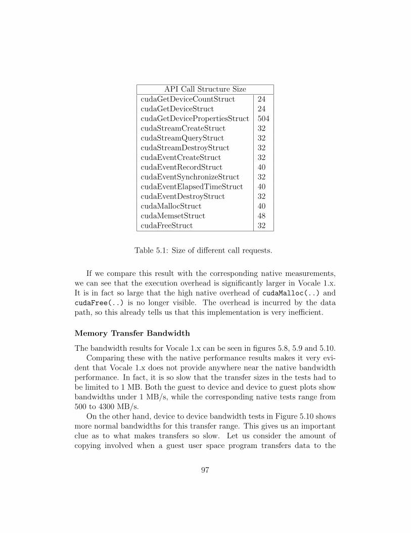
API Call Structure SizecudaGetDeviceCountStruct 24cudaGetDeviceStruct 24cudaGetDevicePropertiesStruct 504cudaStreamCreateStruct 32cudaStreamQueryStruct 32cudaStreamDestroyStruct 32cudaEventCreateStruct 32cudaEventRecordStruct 40cudaEventSynchronizeStruct 32cudaEventElapsedTimeStruct 40cudaEventDestroyStruct 32cudaMallocStruct 40cudaMemsetStruct 48cudaFreeStruct 32
Table 5.1: Size of different call requests.
If we compare this result with the corresponding native measurements,we can see that the execution overhead is significantly larger in Vocale 1.x.It is in fact so large that the high native overhead of cudaMalloc(..) andcudaFree(..) is no longer visible. The overhead is incurred by the datapath, so this already tells us that this implementation is very inefficient.
Memory Transfer Bandwidth
The bandwidth results for Vocale 1.x can be seen in figures 5.8, 5.9 and 5.10.Comparing these with the native performance results makes it very evi-
dent that Vocale 1.x does not provide anywhere near the native bandwidthperformance. In fact, it is so slow that the transfer sizes in the tests had tobe limited to 1 MB. Both the guest to device and device to guest plots showbandwidths under 1 MB/s, while the corresponding native tests range from500 to 4300 MB/s.
On the other hand, device to device bandwidth tests in Figure 5.10 showsmore normal bandwidths for this transfer range. This gives us an importantclue as to what makes transfers so slow. Let us consider the amount ofcopying involved when a guest user space program transfers data to the
97
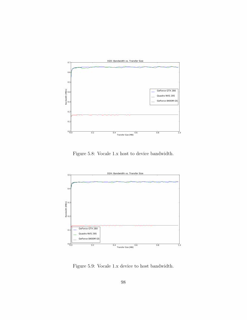
0.0 0.2 0.4 0.6 0.8 1.0Transfer Size [MB]
0.0
0.1
0.2
0.3
0.4
0.5
0.6
0.7Ba
ndw
idth
[MB/
s]
H2D: Bandwidth vs. Transfer Size
GeForce GTX 280
Quadro NVS 295
GeForce 8400M GS
Figure 5.8: Vocale 1.x host to device bandwidth.
0.0 0.2 0.4 0.6 0.8 1.0Transfer Size [MB]
0.0
0.1
0.2
0.3
0.4
0.5
Band
wid
th [M
B/s]
D2H: Bandwidth vs. Transfer Size
GeForce GTX 280
Quadro NVS 295
GeForce 8400M GS
Figure 5.9: Vocale 1.x device to host bandwidth.
98

0.0 0.2 0.4 0.6 0.8 1.0Transfer Size [MB]
0
1000
2000
3000
4000
5000
6000
Band
wid
th [M
B/s]
D2D: Bandwidth vs. Transfer Size
GeForce GTX 280
Quadro NVS 295
GeForce 8400M GS
Figure 5.10: Vocale 1.x device to device bandwidth.
device:
1. The transfer request and data must be copied into the guest’s kernelmemory.
2. The guest copies the transfer request and data to the host through theIOlistener (see Figure 4.4 on page 70).
3. The forwarder executes the transfer with the data from the guest onthe GPU.
That means three copies; the same goes for device to guest and deviceto device transfers. Now, what makes the device to device measurements sonormal is the fact that they copy no transfer data between the guest anddevice - it is just the transfer request with some device memory pointers.Memory transfers between the device and guest, however, have to copy thetransfer data with them as well, and the overhead incurred is very large.For a 10 MB data transfer, the IOlistener is called ten million times totransfer each byte. It is clear that the low bandwidth is caused by the portI/O involved in the second stage.
99
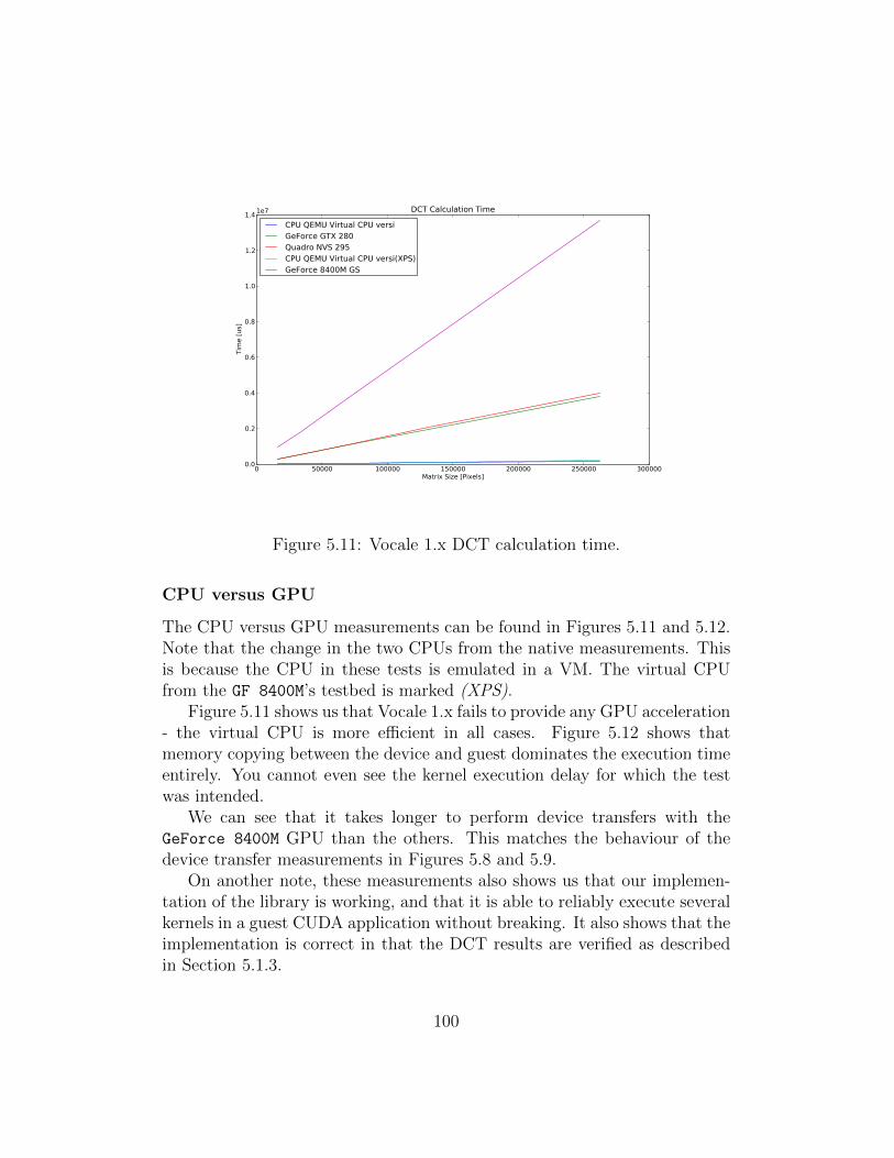
0 50000 100000 150000 200000 250000 300000Matrix Size [Pixels]
0.0
0.2
0.4
0.6
0.8
1.0
1.2
1.4
Tim
e [u
s]
1e7 DCT Calculation Time
CPU QEMU Virtual CPU versiGeForce GTX 280Quadro NVS 295CPU QEMU Virtual CPU versi(XPS)GeForce 8400M GS
Figure 5.11: Vocale 1.x DCT calculation time.
CPU versus GPU
The CPU versus GPU measurements can be found in Figures 5.11 and 5.12.Note that the change in the two CPUs from the native measurements. Thisis because the CPU in these tests is emulated in a VM. The virtual CPUfrom the GF 8400M’s testbed is marked (XPS).
Figure 5.11 shows us that Vocale 1.x fails to provide any GPU acceleration- the virtual CPU is more efficient in all cases. Figure 5.12 shows thatmemory copying between the device and guest dominates the execution timeentirely. You cannot even see the kernel execution delay for which the testwas intended.
We can see that it takes longer to perform device transfers with theGeForce 8400M GPU than the others. This matches the behaviour of thedevice transfer measurements in Figures 5.8 and 5.9.
On another note, these measurements also shows us that our implemen-tation of the library is working, and that it is able to reliably execute severalkernels in a guest CUDA application without breaking. It also shows that theimplementation is correct in that the DCT results are verified as describedin Section 5.1.3.
100
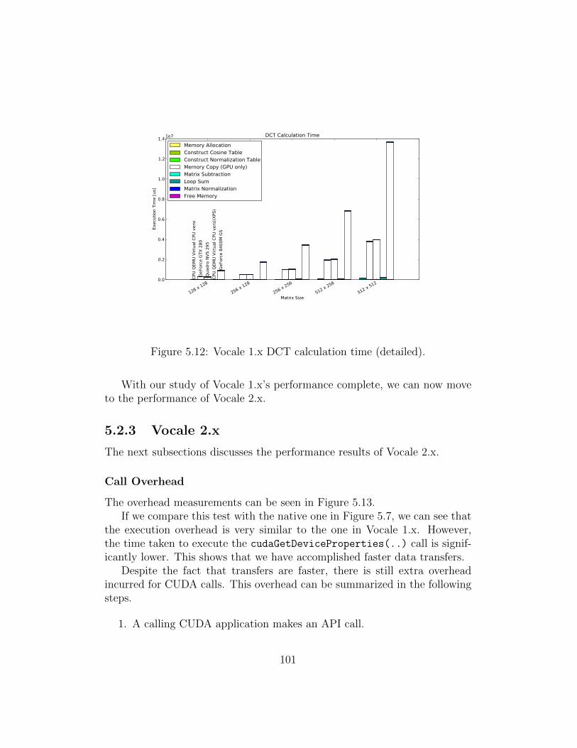
128 x 128
256 x 128
256 x 256
512 x 256
512 x 512
Matrix Size
0.0
0.2
0.4
0.6
0.8
1.0
1.2
1.4
Exec
utio
n Ti
me
[us]
1e7
CPU
QEM
U Vi
rtua
l CPU
ver
siGe
Forc
e GT
X 28
0Qu
adro
NVS
295
CPU
QEM
U Vi
rtua
l CPU
ver
si(X
PS)
GeFo
rce
8400
M G
S
DCT Calculation Time
Memory AllocationConstruct Cosine TableConstruct Normalization TableMemory Copy (GPU only)Matrix SubtractionLoop SumMatrix NormalizationFree Memory
Figure 5.12: Vocale 1.x DCT calculation time (detailed).
With our study of Vocale 1.x’s performance complete, we can now moveto the performance of Vocale 2.x.
5.2.3 Vocale 2.x
The next subsections discusses the performance results of Vocale 2.x.
Call Overhead
The overhead measurements can be seen in Figure 5.13.If we compare this test with the native one in Figure 5.7, we can see that
the execution overhead is very similar to the one in Vocale 1.x. However,the time taken to execute the cudaGetDeviceProperties(..) call is signif-icantly lower. This shows that we have accomplished faster data transfers.
Despite the fact that transfers are faster, there is still extra overheadincurred for CUDA calls. This overhead can be summarized in the followingsteps.
1. A calling CUDA application makes an API call.
101
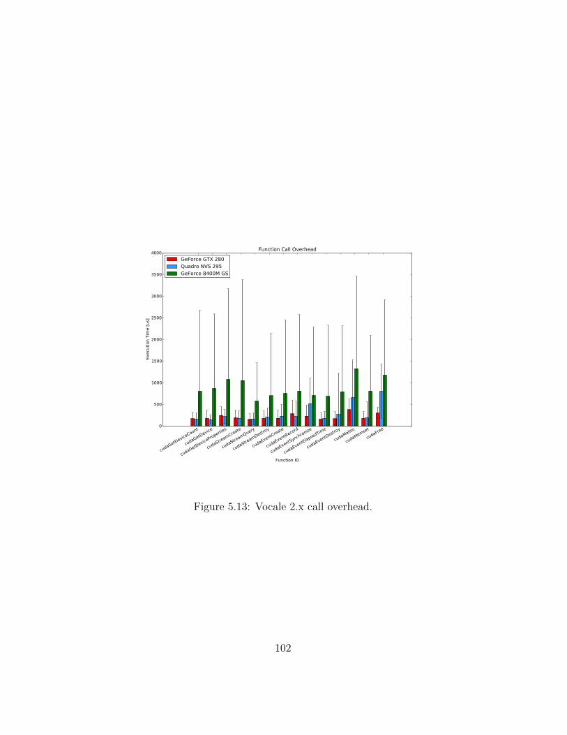
cudaGetDeviceCount
cudaGetDevice
cudaGetDeviceProperties
cudaStreamCreate
cudaStreamQuery
cudaStreamDestroy
cudaEventCreate
cudaEventRecord
cudaEventSynchronize
cudaEventElapsedTime
cudaEventDestroy
cudaMalloc
cudaMemset
cudaFree
Function ID
0
500
1000
1500
2000
2500
3000
3500
4000
Exec
utio
n Ti
me
[us]
Function Call Overhead
GeForce GTX 280Quadro NVS 295GeForce 8400M GS
Figure 5.13: Vocale 2.x call overhead.
102
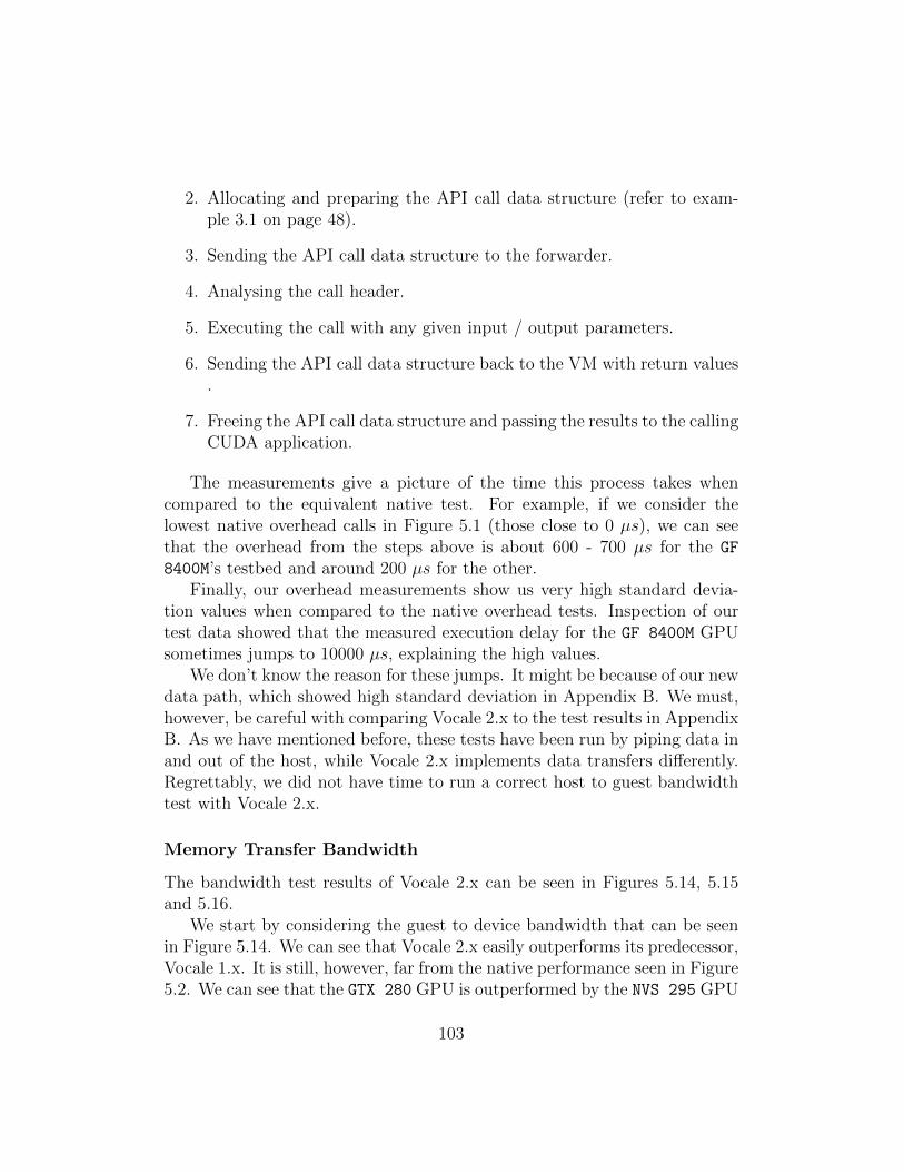
2. Allocating and preparing the API call data structure (refer to exam-ple 3.1 on page 48).
3. Sending the API call data structure to the forwarder.
4. Analysing the call header.
5. Executing the call with any given input / output parameters.
6. Sending the API call data structure back to the VM with return values.
7. Freeing the API call data structure and passing the results to the callingCUDA application.
The measurements give a picture of the time this process takes whencompared to the equivalent native test. For example, if we consider thelowest native overhead calls in Figure 5.1 (those close to 0 µs), we can seethat the overhead from the steps above is about 600 - 700 µs for the GF
8400M’s testbed and around 200 µs for the other.Finally, our overhead measurements show us very high standard devia-
tion values when compared to the native overhead tests. Inspection of ourtest data showed that the measured execution delay for the GF 8400M GPUsometimes jumps to 10000 µs, explaining the high values.
We don’t know the reason for these jumps. It might be because of our newdata path, which showed high standard deviation in Appendix B. We must,however, be careful with comparing Vocale 2.x to the test results in AppendixB. As we have mentioned before, these tests have been run by piping data inand out of the host, while Vocale 2.x implements data transfers differently.Regrettably, we did not have time to run a correct host to guest bandwidthtest with Vocale 2.x.
Memory Transfer Bandwidth
The bandwidth test results of Vocale 2.x can be seen in Figures 5.14, 5.15and 5.16.
We start by considering the guest to device bandwidth that can be seenin Figure 5.14. We can see that Vocale 2.x easily outperforms its predecessor,Vocale 1.x. It is still, however, far from the native performance seen in Figure5.2. We can see that the GTX 280 GPU is outperformed by the NVS 295 GPU
103
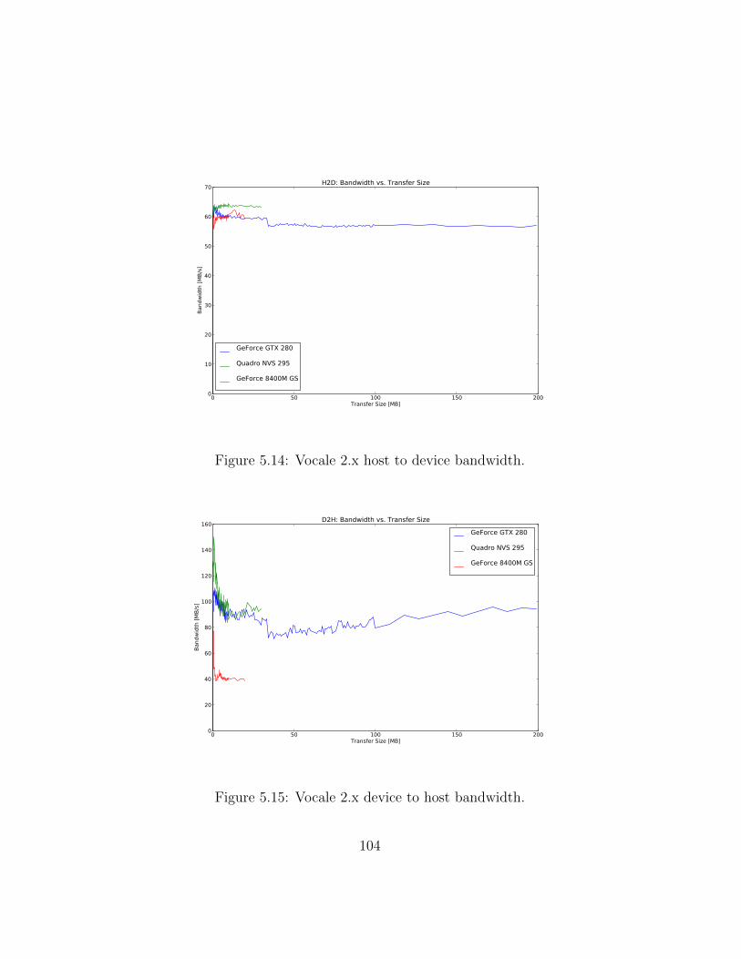
0 50 100 150 200Transfer Size [MB]
0
10
20
30
40
50
60
70
Band
wid
th [M
B/s]
H2D: Bandwidth vs. Transfer Size
GeForce GTX 280
Quadro NVS 295
GeForce 8400M GS
Figure 5.14: Vocale 2.x host to device bandwidth.
0 50 100 150 200Transfer Size [MB]
0
20
40
60
80
100
120
140
160
Band
wid
th [M
B/s]
D2H: Bandwidth vs. Transfer Size
GeForce GTX 280
Quadro NVS 295
GeForce 8400M GS
Figure 5.15: Vocale 2.x device to host bandwidth.
104

0 50 100 150 200Transfer Size [MB]
0
20000
40000
60000
80000
100000
120000Ba
ndw
idth
[MB/
s]
D2D: Bandwidth vs. Transfer Size
GeForce GTX 280
Quadro NVS 295
GeForce 8400M GS
Figure 5.16: Vocale 2.x device to device bandwidth.
by a slight amount. This is because the NVS 295 has a higher native host todevice bandwidth (refer to Figure 5.2).
The device to host bandwidth of Figure 5.15 show the same trend. Theplot is slightly more interesting, however, because the bandwidth is higherfor low transfer sizes, and then degrades. We don’t know why this is, butwe believe that for small transfer sizes the bandwidth of virtio-serial isslightly higher.
Finally, Figure 5.16 shows the internal bandwidth of the GPU. As wediscussed in Section 5.2.2, the results show a bandwidth that is much closerto native standards. When we compare this plot towards the native onein Figure 5.4, we can see that the variations in bandwidth is much moreprominent for the GTX 280 GPU in Vocale 2.x.
It is very peculiar that this GPU shows variations in the bandwidth thatare so drastic, especially when comparing with the other GPUs. Again, wewant to suggest that the reason lies in the number of CUDA cores on theGPU. Our hypothetical explanation is that the the internal data transfersof this GPU finish so fast that they are more susceptible to variations intransfer time from the standard deviation of Vocale’s data path. This is, ofcourse, again based on the assumption that Vocale 2.x’s data path has a high
105
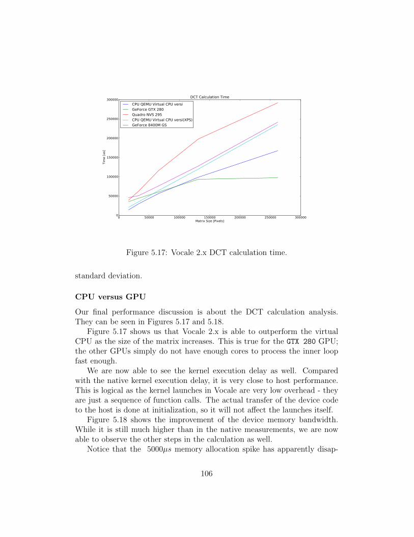
0 50000 100000 150000 200000 250000 300000Matrix Size [Pixels]
0
50000
100000
150000
200000
250000
300000Ti
me
[us]
DCT Calculation Time
CPU QEMU Virtual CPU versiGeForce GTX 280Quadro NVS 295CPU QEMU Virtual CPU versi(XPS)GeForce 8400M GS
Figure 5.17: Vocale 2.x DCT calculation time.
standard deviation.
CPU versus GPU
Our final performance discussion is about the DCT calculation analysis.They can be seen in Figures 5.17 and 5.18.
Figure 5.17 shows us that Vocale 2.x is able to outperform the virtualCPU as the size of the matrix increases. This is true for the GTX 280 GPU;the other GPUs simply do not have enough cores to process the inner loopfast enough.
We are now able to see the kernel execution delay as well. Comparedwith the native kernel execution delay, it is very close to host performance.This is logical as the kernel launches in Vocale are very low overhead - theyare just a sequence of function calls. The actual transfer of the device codeto the host is done at initialization, so it will not affect the launches itself.
Figure 5.18 shows the improvement of the device memory bandwidth.While it is still much higher than in the native measurements, we are nowable to observe the other steps in the calculation as well.
Notice that the 5000µs memory allocation spike has apparently disap-
106
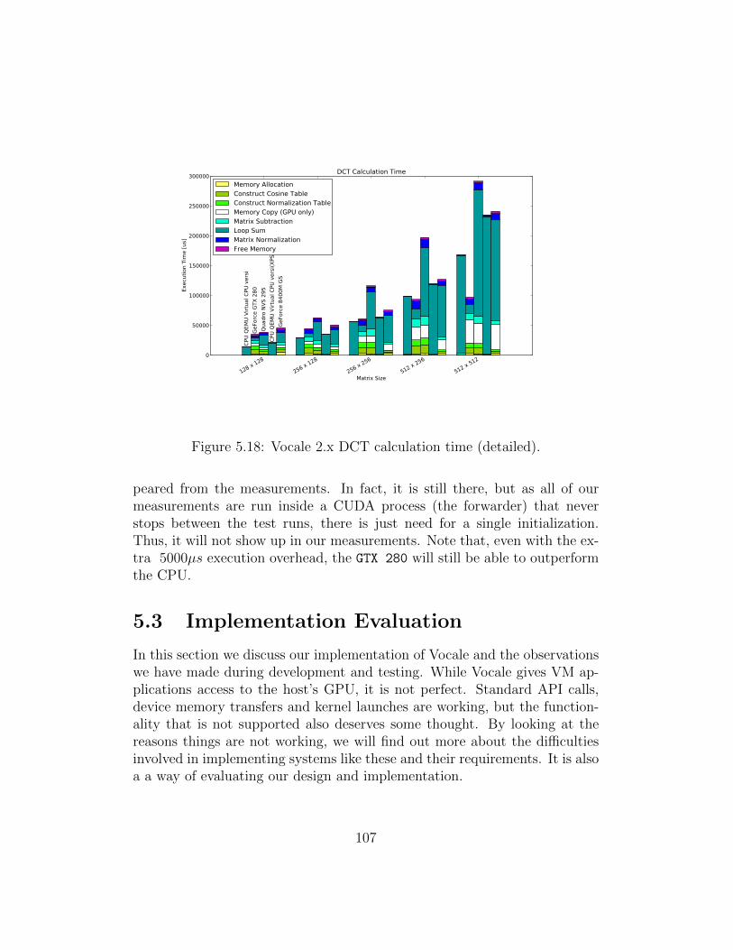
128 x 128
256 x 128
256 x 256
512 x 256
512 x 512
Matrix Size
0
50000
100000
150000
200000
250000
300000Ex
ecut
ion
Tim
e [u
s]
CPU
QEM
U Vi
rtua
l CPU
ver
siGe
Forc
e GT
X 28
0Qu
adro
NVS
295
CPU
QEM
U Vi
rtua
l CPU
ver
si(X
PS)
GeFo
rce
8400
M G
S
DCT Calculation Time
Memory AllocationConstruct Cosine TableConstruct Normalization TableMemory Copy (GPU only)Matrix SubtractionLoop SumMatrix NormalizationFree Memory
Figure 5.18: Vocale 2.x DCT calculation time (detailed).
peared from the measurements. In fact, it is still there, but as all of ourmeasurements are run inside a CUDA process (the forwarder) that neverstops between the test runs, there is just need for a single initialization.Thus, it will not show up in our measurements. Note that, even with the ex-tra 5000µs execution overhead, the GTX 280 will still be able to outperformthe CPU.
5.3 Implementation Evaluation
In this section we discuss our implementation of Vocale and the observationswe have made during development and testing. While Vocale gives VM ap-plications access to the host’s GPU, it is not perfect. Standard API calls,device memory transfers and kernel launches are working, but the function-ality that is not supported also deserves some thought. By looking at thereasons things are not working, we will find out more about the difficultiesinvolved in implementing systems like these and their requirements. It is alsoa a way of evaluating our design and implementation.
107
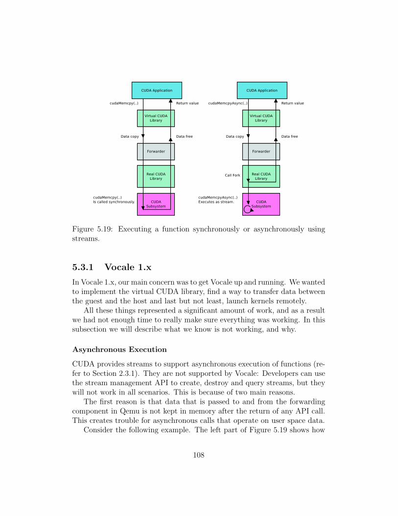
Figure 5.19: Executing a function synchronously or asynchronously usingstreams.
5.3.1 Vocale 1.x
In Vocale 1.x, our main concern was to get Vocale up and running. We wantedto implement the virtual CUDA library, find a way to transfer data betweenthe guest and the host and last but not least, launch kernels remotely.
All these things represented a significant amount of work, and as a resultwe had not enough time to really make sure everything was working. In thissubsection we will describe what we know is not working, and why.
Asynchronous Execution
CUDA provides streams to support asynchronous execution of functions (re-fer to Section 2.3.1). They are not supported by Vocale: Developers can usethe stream management API to create, destroy and query streams, but theywill not work in all scenarios. This is because of two main reasons.
The first reason is that data that is passed to and from the forwardingcomponent in Qemu is not kept in memory after the return of any API call.This creates trouble for asynchronous calls that operate on user space data.
Consider the following example. The left part of Figure 5.19 shows how
108
a synchronous cudaMemcpy(..) call is handled. Once the call is interceptedby the virtual CUDA library, the call request and any data accompanyingthe call is copied into a new buffer that is presented to the forwarder (referto Section 3.3 for a description of Vocale’s components). The forwarder inturn executes the call on the real CUDA library, which handles the call andreturns. Finally, the return data is sent back to the virtual library and thecalling CUDA application, and the data buffer is freed in the process.
Now consider what happens when the CUDA application attempts to ex-ecute the asynchronous version of cudaMemcpy(..); cudaMemcpyAsync(..),in a stream. Refer to the right side of Figure 5.19. The call and accompa-nying data is transferred to the forwarder just like the synchronous call, butwhen the forwarder executes it, the call forks:
1. The calling thread immediately returns, passing back any return valueto the virtual CUDA library and the calling CUDA application. Thedata buffer is freed.
2. Internally, the CUDA subsystem creates its own thread. This threadtakes care of the execution of the asynchronous call.
It is easy to see what is going wrong here. Once the calling thread returnsto the virtual CUDA library, the data buffer is freed. Asynchronous calls likecudaMemcpyAsync(..) keep working on this data - and creates a catastrophicmemory access error that will crash the Qemu process.
The second reason streams are unsupported is that there is no asyn-chronous event notification mechanism implemented in the data transfermechanism. In fact, the data transfer mechanism in Vocale 1.x only re-sponds to calls from the VM. Qemu and the forwarder can do nothing to”wake up” the guest to transfer data.
Event notification is necessary for asynchronous functions which producesome kind of output to be copied back into the guest. Let us again considerthe right part of Figure 5.19. The CUDA application running in the guesthas just requested to copy some data from the device into a user space bufferusing cudaMemcpyAsync(..). The call progresses down to the forwarder inQemu and forks. The calling thread returns immediately, while the CUDAlibrary starts working on the data transfer in its own thread. Now, considerthe situation when the stream is done and output has been produced. Thedata needs to be transferred back to the CUDA application, but becausethere is no way to notify it that data is available, it is lost.
109

Multiple Guest CUDA Applications
Vocale 1.x does not support multiple CUDA processes running in the guest.The reason is that Vocale was never designed to be used by several CUDAprocesses in the guest at the same time. However, this cannot be ignored insystems targeted for normal usage.
The reason multiple CUDA applications do not work in Vocale 1.x is arace condition. Let us take another brief look at how data is transferredbetween the virtual CUDA library and the forwarder.
Figure 5.20: Call forwarding through Vocale’s subsystems.
Figure 5.20 shows the steps taken by the virtual CUDA library to exe-cute a function call remotely. When a CUDA call is intercepted, it sends acall identifier and any data accompanying the call to Vocale’s subsystem bywriting the IOlistener kernel module. Vocale’s subsystem executes the callnatively and prepares the result of the function call, which the virtual libraryretrieves by reading the IOlistener kernel module.
Figure 5.21: Race condition in Vocale.
110
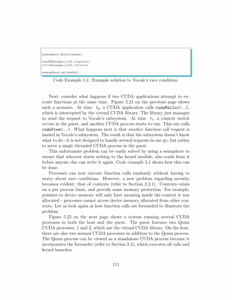
semaphore down (mutex )
sendMessage ( c a l l r e q u e s t )recvMessage ( c a l l r e t u r n )
semaphore up (mutex )
Code Example 5.1: Example solution to Vocale’s race condition.
Next, consider what happens if two CUDA applications attempt to ex-ecute functions at the same time. Figure 5.21 on the previous page showssuch a scenario. At time t0, a CUDA application calls cudaMalloc(..),which is intercepted by the virtual CUDA library. The library just managesto send the request to Vocale’s subsystem. At time t1, a context switchoccurs in the guest, and another CUDA process starts to run. This one callscudaFree(..). What happens next is that another function call request islanded in Vocale’s subsystem. The result is that the subsystem doesn’t knowwhat to do - it is not designed to handle several requests in one go, but ratherto serve a single threaded CUDA process in the guest.
This unfortunate problem can be easily solved by using a semaphore toensure that whoever starts writing to the kernel module, also reads from itbefore anyone else can write it again. Code example 5.1 shows how this canbe done.
Processes can now execute function calls randomly without having toworry about race conditions. However, a new problem regarding securitybecomes evident; that of contexts (refer to Section 2.3.1). Contexts existson a per process basis, and provide some memory protection. For example,pointers to device memory will only have meaning inside the context it wasallocated - processes cannot access device memory allocated from other con-texts. Let us look again at how function calls are forwarded to illustrate theproblem.
Figure 5.22 on the next page shows a system running several CUDAprocesses in both the host and the guest. The guest features two QemuCUDA processes, 1 and 2, which use the virtual CUDA library. On the host,there are also two normal CUDA processes in addition to the Qemu process.The Qemu process can be viewed as a standalone CUDA process because itincorporates the forwarder (refer to Section 3.3), which executes all calls andkernel launches.
111
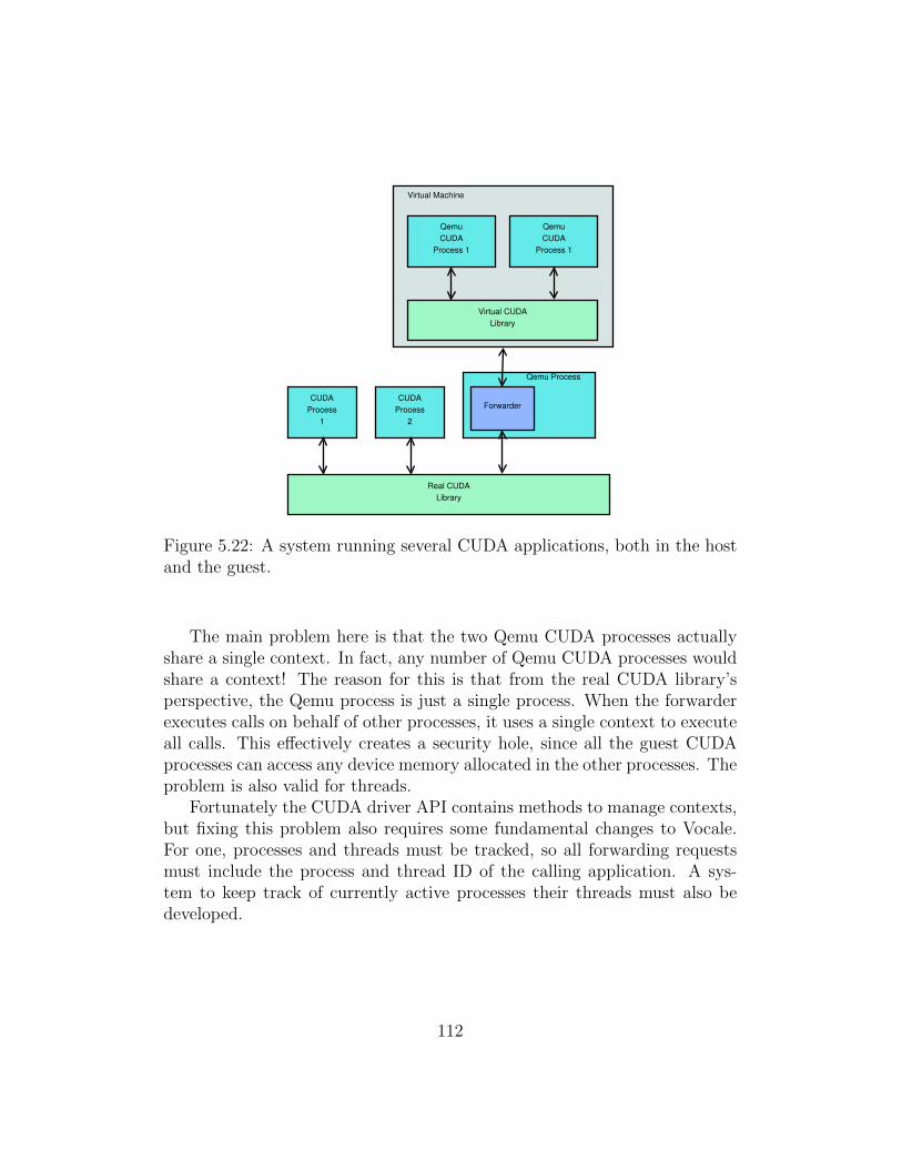
Real CUDA
Library
CUDA
Process
1
CUDA
Process
2
Virtual Machine
Virtual CUDA
Library
Qemu
CUDA
Process 1
Qemu
CUDA
Process 1
Qemu Process
Forwarder
Figure 5.22: A system running several CUDA applications, both in the hostand the guest.
The main problem here is that the two Qemu CUDA processes actuallyshare a single context. In fact, any number of Qemu CUDA processes wouldshare a context! The reason for this is that from the real CUDA library’sperspective, the Qemu process is just a single process. When the forwarderexecutes calls on behalf of other processes, it uses a single context to executeall calls. This effectively creates a security hole, since all the guest CUDAprocesses can access any device memory allocated in the other processes. Theproblem is also valid for threads.
Fortunately the CUDA driver API contains methods to manage contexts,but fixing this problem also requires some fundamental changes to Vocale.For one, processes and threads must be tracked, so all forwarding requestsmust include the process and thread ID of the calling application. A sys-tem to keep track of currently active processes their threads must also bedeveloped.
112
CPU Stall
Vocale 1.x makes relatively straightforward use of I/O ports to realise datatransfers between the host and the guest (refer to Section 4.2). When theguest writes and reads data to and from certain I/O ports, handlers in theIOlistener track the transmission of data. When messages have been re-ceived, it calls the forwarder, which analyses the data received and executesfunctions and kernels as appropriate.
Unfortunately, this creates a problem with big data transfers which isbest characterized as a form of CPU stall. Normally, when a CPU writesI/O ports, the value of that port is transferred immediately into one of theprocessor’s hardware registers. In Qemu, however, a handler function is calledin the IOlistener, so there is some extra overhead incurred when readingand writing I/O ports. No further investigation was made to find the rootcause of this problem, but our hypothesis is that the I/O port handlers arerun in the main CPU thread of Qemu, effectively halting all CPU operationsin the VM until the handler is complete.
Automatic Code Generation
Section 4.2.2 discusses the implementation of the virtual CUDA library andaddresses the problem that there are about 220 function calls that needsto be implemented as part of it. Each call requires an implementation inthe host (forwarder), guest (as part of the library) as well as shared datastructures (call structures and function identifiers).
A Python script was developed to address this problem. Our implementa-tion takes a single header file as input, recursively searching any sub-includedheaders for function declarations. It successfully generates the following:
- An implementation of each function for the virtual CUDA library.
- Call identifiers and function parameter data structures.
- An implementation to execute each function from the forwarder.
Scripts like these should use common parsing techniques found in com-pilers to search for function declarations, but our implementation does not.It relies on a neatly written header where each new line is a new statement,and easily breaks with more messy header files. Fortunately, NVIDIA’s de-velopers did a good job here.
113
Now, aside from critiques, there were two key challenges that proved thisjob difficult.
Distinguishing input and output parameters. The return value of eachlibrary call is already used for error values, so any input / output pa-rameters must be assigned in the parameter list. In C/C++, functionparameters are copied onto the CPU’s stack and lost when the functionreturns. Thus any output parameter must be denoted as a single ordouble pointer which points to the output variable in memory.
The void data type. Void denotes a data type which has no value. Acommon use is as a generic memory pointer (void*), for example for thedevice memory transfer functions in the CUDA API. The problem withthis is that it can be both input and output parameter. Also, dependingon the scenario, a size parameter may accompany the function. Forthis reason the memory transfer functions in the virtual library mustbe implemented manually. The alternative is to see if a pattern canbe found to auto generate functions which involve parameters of thevoid* type.
This concludes our discussion of Vocale 1.x. The next subsection discussesthe implementation of Vocale 2.x, which solves the two main issues of itspredecessor.
5.3.2 Vocale 2.x
Our experiences with Vocale 1.x in the previous section show two main prob-lems:
• The low bandwidth of memory transfers between device and guest. Aswe saw in our CPU versus GPU test of Section 5.2.2, these entirelydominate the performance of our DCT program.
• The CPU stall (refer to Section 5.3.1). This prevents users of VMs toactually be able to use their machine while performing device memorytransfers.
The motivation of Vocale 2.x was thus to solve these issues. To addressthis, we moved away from our own implementation of port I/O data transfers
114
and used Qemu’s own framework for virtual hardware and virtio-serial
(refer to Section 4.3.1). The reason for doing this was our performancemeasurements show in Appendix B.
Our results show us, however, that while we get a good bandwidth in-crease from using virtio-serial, it is nothing close to the native bandwidth.It is also lower than expected, but this is because our Virtio measurementsshow the bandwidth between the guest and the host, and not the guest anddevice. There is thus an extra copy involved to copy data from the host tothe device.
At any rate, using Qemu’s Virtio framework for guest / host data transferssolved the CPU stall mentioned previously.
In this chapter, we have discussed the implementation and performanceof Vocale. The purpose of this has been to find out how well Vocale wasdesigned and implemented, and we also wanted to find out what kind ofdemands a system like Vocale places on its hypervisor. In the next chapter,we will make our concluding remarks on these matters.
115

Chapter 6
Conclusion and Further Work
In our final chapter we sum up our results discussion to make our final conclu-sive remarks. We answer our problem statement by looking at our experiencesand results of Vocale.
The chapter layout is as follows. The first section describes the challengesrelated to the development of virtual GPUs, especially in the context ofremote procedure calling of GPGPU libraries. These are closely intertwinedwith our implementation and performance evaluation in the previous chapter.
The second and final section outlines future work, where we propose solu-tions to the issues highlighted in the results chapter. We also present the startof Vocale 3.x, a shared memory implementation that was never completed.We sum up our work with an overall assessment of our work.
6.1 Challenges of GPU Virtualization
In our problem statement, we ask what the challenges of GPU virtualizationare. This section attempts to answer that by using our implementation andperformance results of Vocale.
6.1.1 Large Data Transfers
Our test results of Vocale 2.x show us that the device memory transfer band-width is very low compared to native standards. From our runtime analysisof the DCT calculation, we also see that GPU accelerated programs are eas-ily outperformed by the CPU if they perform too many data transfers. This
116

renders the device memory bandwidth as an important bottleneck of Vocale2.x.
In our work with Qemu we have not found a way to transfer data betweenthe host and the guest that is efficient enough for GPU applications. Theframeworks that exists are built for much smaller transfer sizes than thosedemanded by GPU applications - clipboard operations, packet transmissionet cetra. We recognize the need for a new way to effectively share data di-rectly between the guest and the host, that at the same time avoids reservingphysical memory, as is GViM’s approach.
Host / guest data transfers would be simple if not for the MMU of modernCPUs. While all the memory of a guest CUDA application essentially residesin the same physical memory as the hypervisor’s, the MMUs in the host andthe guest makes it impossible to access the memory directly between thetwo worlds. Memory is fragmented, swapped out to disk and changed atarbitrary times - in addition, a memory pointer in the guest has no meaningin the host, and vice versa.
This holds true for any design paradigm, front end or back end, of anyvirtual GPU used for general purpose computing. As long as the virtual GPUis backed by a physical one in the host, large data transfers will have to takeplace between the GPU and the guest. There is just no transfer mechanismin Qemu that supports this purpose.
6.1.2 Library Virtualization
One of the main reasons for choosing front end virtualization in the form ofa virtual CUDA library was to avoid dealing in proprietary details. It wasassumed that a virtual library is just a collection of function calls that canbe easily forwarded through the VM layer. We predicted some work withresolving hidden functionality in the library. Our experience with Vocaleproves this hypothesis wrong; in that not a little, but a great deal of timehas been spent figuring out how to remotely launch kernels. Virtualizing alibrary like CUDA is therefore not as straightforward as one might think,depending on how well the internal functionality of the library is hidden.The issue of finding the size of the fat binary object in Section 4.2.2 is aprime example.
The need to automatically generate code quickly became evident duringthe implementation. As described in Section 5.3.1, the total number of func-tions in the CUDA API is around 220, each of which requires three separate
117
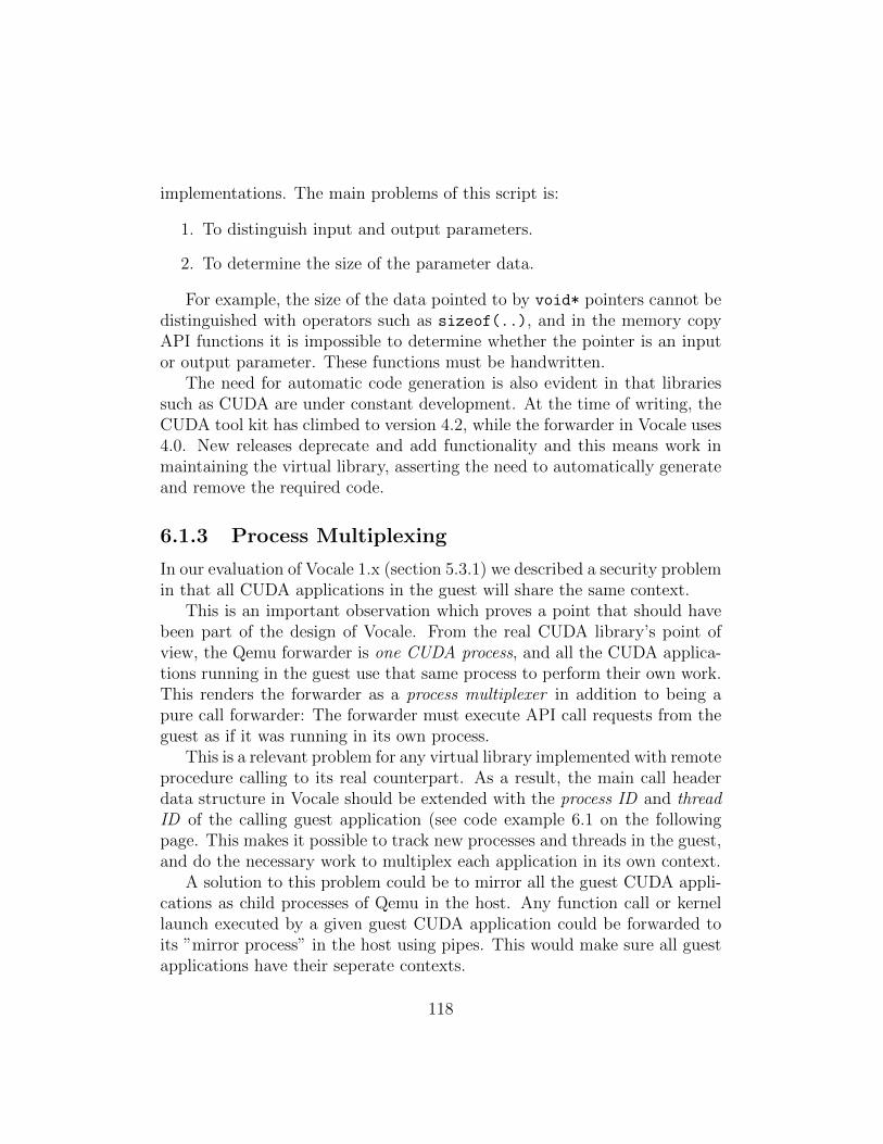
implementations. The main problems of this script is:
1. To distinguish input and output parameters.
2. To determine the size of the parameter data.
For example, the size of the data pointed to by void* pointers cannot bedistinguished with operators such as sizeof(..), and in the memory copyAPI functions it is impossible to determine whether the pointer is an inputor output parameter. These functions must be handwritten.
The need for automatic code generation is also evident in that librariessuch as CUDA are under constant development. At the time of writing, theCUDA tool kit has climbed to version 4.2, while the forwarder in Vocale uses4.0. New releases deprecate and add functionality and this means work inmaintaining the virtual library, asserting the need to automatically generateand remove the required code.
6.1.3 Process Multiplexing
In our evaluation of Vocale 1.x (section 5.3.1) we described a security problemin that all CUDA applications in the guest will share the same context.
This is an important observation which proves a point that should havebeen part of the design of Vocale. From the real CUDA library’s point ofview, the Qemu forwarder is one CUDA process, and all the CUDA applica-tions running in the guest use that same process to perform their own work.This renders the forwarder as a process multiplexer in addition to being apure call forwarder: The forwarder must execute API call requests from theguest as if it was running in its own process.
This is a relevant problem for any virtual library implemented with remoteprocedure calling to its real counterpart. As a result, the main call headerdata structure in Vocale should be extended with the process ID and threadID of the calling guest application (see code example 6.1 on the followingpage. This makes it possible to track new processes and threads in the guest,and do the necessary work to multiplex each application in its own context.
A solution to this problem could be to mirror all the guest CUDA appli-cations as child processes of Qemu in the host. Any function call or kernellaunch executed by a given guest CUDA application could be forwarded toits ”mirror process” in the host using pipes. This would make sure all guestapplications have their seperate contexts.
118
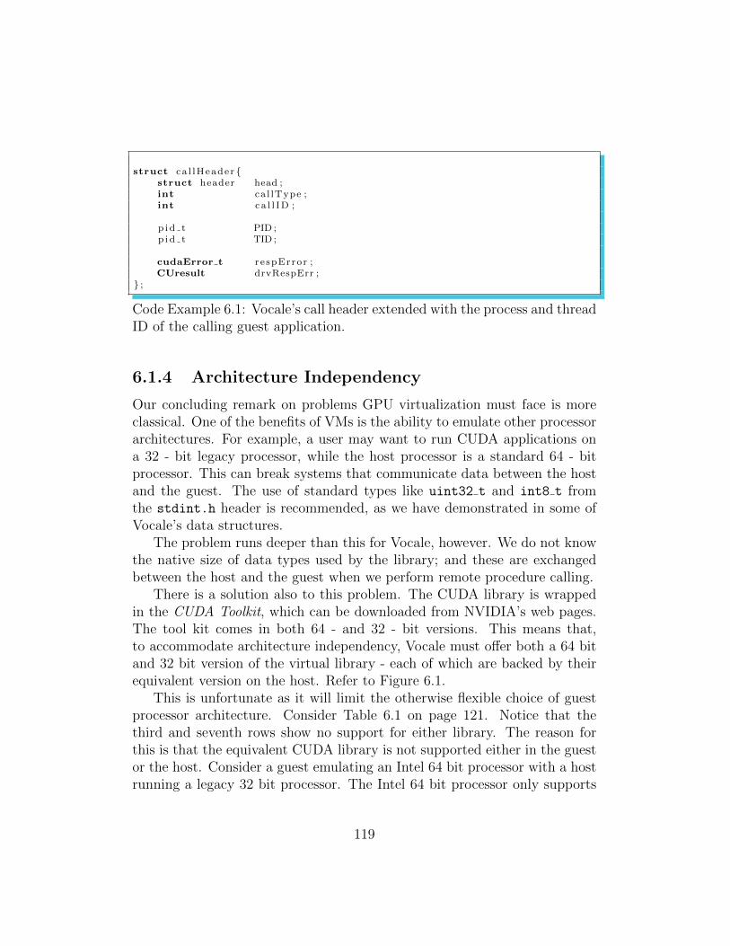
struct ca l lHeader {struct header head ;int ca l lType ;int ca l l ID ;
p i d t PID ;p i d t TID ;
cudaError t r e spError ;CUresult drvRespErr ;
} ;
Code Example 6.1: Vocale’s call header extended with the process and threadID of the calling guest application.
6.1.4 Architecture Independency
Our concluding remark on problems GPU virtualization must face is moreclassical. One of the benefits of VMs is the ability to emulate other processorarchitectures. For example, a user may want to run CUDA applications ona 32 - bit legacy processor, while the host processor is a standard 64 - bitprocessor. This can break systems that communicate data between the hostand the guest. The use of standard types like uint32 t and int8 t fromthe stdint.h header is recommended, as we have demonstrated in some ofVocale’s data structures.
The problem runs deeper than this for Vocale, however. We do not knowthe native size of data types used by the library; and these are exchangedbetween the host and the guest when we perform remote procedure calling.
There is a solution also to this problem. The CUDA library is wrappedin the CUDA Toolkit, which can be downloaded from NVIDIA’s web pages.The tool kit comes in both 64 - and 32 - bit versions. This means that,to accommodate architecture independency, Vocale must offer both a 64 bitand 32 bit version of the virtual library - each of which are backed by theirequivalent version on the host. Refer to Figure 6.1.
This is unfortunate as it will limit the otherwise flexible choice of guestprocessor architecture. Consider Table 6.1 on page 121. Notice that thethird and seventh rows show no support for either library. The reason forthis is that the equivalent CUDA library is not supported either in the guestor the host. Consider a guest emulating an Intel 64 bit processor with a hostrunning a legacy 32 bit processor. The Intel 64 bit processor only supports
119
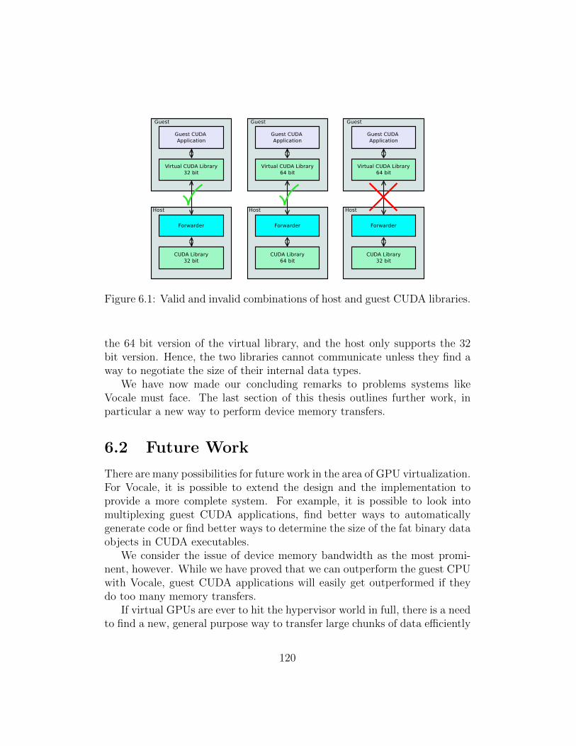
Figure 6.1: Valid and invalid combinations of host and guest CUDA libraries.
the 64 bit version of the virtual library, and the host only supports the 32bit version. Hence, the two libraries cannot communicate unless they find away to negotiate the size of their internal data types.
We have now made our concluding remarks to problems systems likeVocale must face. The last section of this thesis outlines further work, inparticular a new way to perform device memory transfers.
6.2 Future Work
There are many possibilities for future work in the area of GPU virtualization.For Vocale, it is possible to extend the design and the implementation toprovide a more complete system. For example, it is possible to look intomultiplexing guest CUDA applications, find better ways to automaticallygenerate code or find better ways to determine the size of the fat binary dataobjects in CUDA executables.
We consider the issue of device memory bandwidth as the most promi-nent, however. While we have proved that we can outperform the guest CPUwith Vocale, guest CUDA applications will easily get outperformed if theydo too many memory transfers.
If virtual GPUs are ever to hit the hypervisor world in full, there is a needto find a new, general purpose way to transfer large chunks of data efficiently
120
HostArchi-tecture
GuestArchi-tecture
Guest 32-bitCUDA librarysupport
Guest 64-bitCUDA librarysupport
x86 x86 Yes Nox86 x86 64 Yes Nox86 Intel 64 No Nox86 64 x86 Yes Nox86 64 x86 64 Yes Yesx86 64 Intel 64 No YesIntel 64 x86 No NoIntel 64 x86 64 No YesIntel 64 Intel 64 No Yes
Table 6.1: Architectural compatibility between Vocale’s guest and host en-vironments.
between the guest and the host. Ideally, we’d like to see such a mechanismas a part of the Virtio implementation. This way it could benefit virtualhardware in general, and not only our implementation of Vocale.
The subsection in this section outlines our start of such an implementa-tion, inspired by Virtio[25] itself.
6.2.1 Zero Copy Data Transfers and Vocale 3.x
The Virtio article[25, Section 4.1] states the possibility for zero copy datatransfers between hosts and guests as an alternative to its own data transfermechanism. It is suggested that, for large data transfers, a technique calledpage flipping may improve the efficiency of the transfer. This has not beenimplemented in Virtio, but the article suggests for an enthusiast to prove theusefulness of page flipping. Possible future work for Vocale is to implementthis and investigate if it can provide any acceleration over Vocale 2.x.
The intention of page flipping is to achieve zero-copy data transfers be-tween the host and the guest. This is done by exploiting the fact that thephysical memory of a guest can be accessed through the virtual address spaceof the hypervisor. Figure 6.2 on the following page shows such a scenario,where a guest CUDA application makes a request to copy some data to theGPU. The following list explains in short how we think this can be done.
121
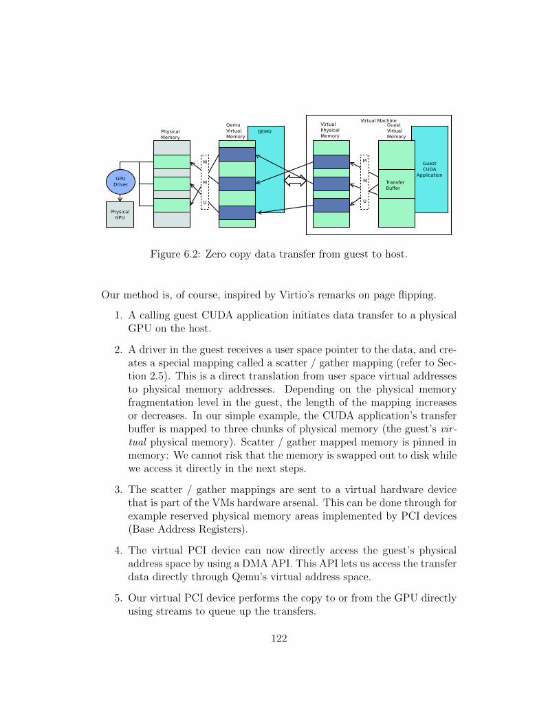
Figure 6.2: Zero copy data transfer from guest to host.
Our method is, of course, inspired by Virtio’s remarks on page flipping.
1. A calling guest CUDA application initiates data transfer to a physicalGPU on the host.
2. A driver in the guest receives a user space pointer to the data, and cre-ates a special mapping called a scatter / gather mapping (refer to Sec-tion 2.5). This is a direct translation from user space virtual addressesto physical memory addresses. Depending on the physical memoryfragmentation level in the guest, the length of the mapping increasesor decreases. In our simple example, the CUDA application’s transferbuffer is mapped to three chunks of physical memory (the guest’s vir-tual physical memory). Scatter / gather mapped memory is pinned inmemory: We cannot risk that the memory is swapped out to disk whilewe access it directly in the next steps.
3. The scatter / gather mappings are sent to a virtual hardware devicethat is part of the VMs hardware arsenal. This can be done through forexample reserved physical memory areas implemented by PCI devices(Base Address Registers).
4. The virtual PCI device can now directly access the guest’s physicaladdress space by using a DMA API. This API lets us access the transferdata directly through Qemu’s virtual address space.
5. Our virtual PCI device performs the copy to or from the GPU directlyusing streams to queue up the transfers.
122
6. When the streams and data transfer is complete, our virtual PCI devicenotifies the guest that the task is complete using hardware interrupts.
7. The driver in the guest releases the scatter / gather mappings. TheCUDA application’s data buffer is unpinned from memory, and thetransfer is complete.
A folder named vocale-3.x can be found in Vocale’s source tree. Thisis an unfinished implementation of page flipping that is inspired of a sharedmemory implementation called ivshem (refer to src/hw/ivshmem.c). Wewill not go into implementation specific details, as this is now out of scopefor the thesis. We will, however, describe the basic concepts so that someonecan pick up the work. The implementation consists of the following:
• A virtual PCI device called zcpy. Its source code can be found insrc/hw/zcpy.c/.h.
• A new driver for the PCI device. The source code can be found indriver/zcpy.c/.h.
Basically, the following has been achieved:
• Automatically load the driver for the virtual zcpy PCI device on boot.
• Reserve physical memory areas that can be used for passing smallamounts of data directly between the host and the guest; for exam-ple forwarding requests and scatter / gather mappings.
• The kernel module’s user space interface is no longer implemented asread / write calls to the device file, but as ioctl commands[5, Chapter6] (similar to system calls).
The idea of the zcpy device is to allow for mapping guest virtual mem-ory addresses to the physical memory address space using scatter / gathermappings. These mappings can be sent directly to the zcpy hardware im-plementation in Qemu; from there, it is a matter of using Qemu’s PCI DMAAPI to perform device memory transfers directly.
Anyone is free to continue the work, which should focus on implementingthe following:
123
• Assigning hardware interrupts to the zcpy device to allow asynchronousevent notification. There is an API in Qemu for doing this, and it isalso possible to look at the implementation of ivshmem.
• Memory map zcpy’s reserved physical memory areas directly into thetransfer library in the guest to allow zero-copy forwarding requests.
• Finish the implementation of scatter/gather mappings in the driver, toallow for mapping guest virtual memory to the guest’s physical addressspace. The process of creating these mappings can be found in [5,Chapter 15].
• Verify and profile the bandwidth of the new implementation. It is notguaranteed that zero copy transfers will increase the efficiency of datatransfers in Vocale. This depends solely on the implementation of thePCI DMA API and how fast it is, and is up to future work to find out.The PCI DMA API is necessary as the hypervisor has by default noaccess to the physical memory of the guest.
Our work with Vocale shows that VMs are able to benefit from GPUacceleration by emulating CUDA. We also see, however, that there are newchallenges that needs to be solved for virtual GPUs to be a viable alternativeto normal CPU processing in VMs. These challenges comprise issues ofsecurity, performance and maintainability. Once this is in place it is naturalthat VMs should provide GPU acceleration to their environment.
Our most important observation is that we can find no mechanism fordata transfers in hypervisor environments optimized for large data trans-fers. GViM (refer to Section 2.6.2) solves this problem by reserving physicalmemory to allow zero-copy of data, but this approach can deplete systemresources quickly. Nonetheless, we do not think there are any solutions thatare faster: The next best thing is to perform page flipping, and that willdemand some overhead in creating scatter / gather mappings, as well aspinning down memory.
We believe a combination of page flipping and the approaches to reservememory taken by GViM will create a good solution, but this is for futurework to find out.
124
Bibliography
[1] Virtio serial - features. Web.http://fedoraproject.org/wiki/Features/VirtioSerial (26/4/2012).
[2] The gnu make manual. Web, July 2010.http://www.gnu.org/software/make/manual/make.html (26/4/2012).
[3] Paul Barham, Boris Dragovic, Keir Fraser, Steven Hand, Tim Harris,Alex Ho, Rolf Neugebauer, Ian Pratt, and Andrew Warfield. Xen andthe art of virtualization. SIGOPS Oper. Syst. Rev., 37:164–177, October2003.
[4] Wayne Carlson. A critical history of computer graphics and animation.Web, 2003.https://design.osu.edu/carlson/history/lessons.html (26/4/2012).
[5] Jonathan Corbet, Alessandro Rubini, and Greg Kroah-Hartman. Linuxdevice drivers. Number 3rd ed. O’Reilly, 2005.
[6] NVIDIA Corporation. Cuda api reference manual. Web.http://developer.download.nvidia.com/compute/DevZone/docs/html/C/doc/CUDA Toolkit Reference Manual.pdf (26/4/2012).
[7] NVIDIA Corporation. The cuda compiler driver documentation. Web.Included in Cuda Toolkit v.4.0 documentation.http://developer.nvidia.com/cuda-toolkit-40rc2 (26/4/2012).
[8] NVIDIA Corporation. Cuda programming guide. Web.http://developer.download.nvidia.com/compute/DevZone/docs/html/C/doc/CUDA C Programming Guide.pdf (26/4/2012).
[9] NVIDIA Corporation. What is cuda?http://www.nvidia.com/object/cuda home new.html (26/4/2012).
125
[10] NVIDIA Corporation. Cuda best practices guide. Web, January 2012.http://developer.download.nvidia.com/compute/DevZone/docs/html/C/doc/CUDA C Best Practices Guide.pdf (26/4/2012).
[11] Oracle Corporation. Oracle vm virtualbox: User manual. Technicalreport, Oracle, 2011.download.virtualbox.org/virtualbox/UserManual.pdf (26/4/2012).
[12] INF5063 Course. x86 and mjpeg presentation. Web, August 2011.http://www.uio.no/studier/emner/matnat/ifi/INF5063/h11/undervisningsmateriale/INF5063-03-x86-MJPEG.pptx (26/4/2012).
[13] R. J. Creasy. The origin of the vm/370 time-sharing system. IBMJournal of Research and Development, 25(5):483–490, 1981.
[14] Micah Dowty and Jeremy Sugerman. Gpu virtualization on vmware’shosted i/o architecture. In Proceedings of the First conference on I/Ovirtualization, WIOV’08, pages 7–7, Berkeley, CA, USA, 2008. USENIXAssociation.
[15] Matteo Frigo and Steven G. Johnson. The design and implementationof FFTW3. Proceedings of the IEEE, 93(2):216–231, 2005. Special issueon “Program Generation, Optimization, and Platform Adaptation”.
[16] PCI Special Interest Group. I/o virtualization - address translationservices. Web.http://www.pcisig.com/specifications/iov/ats (26/4/2012).
[17] Vishakha Gupta, Ada Gavrilovska, Karsten Schwan, HarshvardhanKharche, Niraj Tolia, Vanish Talwar, and Parthasarathy Ranganathan.Gvim: Gpu-accelerated virtual machines. In Proceedings of the 3rd ACMWorkshop on System-level Virtualization for High Performance Com-puting, HPCVirt ’09, pages 17–24, New York, NY, USA, 2009. ACM.
[18] T. Kilburn, D. B. G. Edwards, M. J. Lanigan, and F. H. Sumner. One-level storage system. Electronic Computers, IRE Transactions on, EC-11(2):223 –235, april 1962.
[19] M. A. McCormack, T. T. Schansman, and K. K. Womack. 1401 com-patibility feature on the ibm system/360 model 30. Commun. ACM,8:773–776, December 1965.
126
[20] Susanta Nanda and Tzi cker Chiueh. A survey of virtualization technolo-gies. Technical report, Stony Brook University, Department of ComputerScience, 2005.
[21] Gerard O’Regan. A Brief History of Computing. Springer-Verlag Lon-don Limited, London, 2008.
[22] J. D. Owens, M. Houston, D. Luebke, S. Green, J. E. Stone, and J. C.Phillips. Gpu computing. IEEE J PROC, 96(5):879–899, 2008.
[23] Gerald J. Popek and Robert P. Goldberg. Formal requirements for vir-tualizable third generation architectures. Commun. ACM, 17:412–421,July 1974.
[24] Qemu. Getting started for developers. Web.http://wiki.qemu.org/Documentation/GettingStartedDevelopers(26/4/2012).
[25] R. Russel. virtio: towards a de-facto standard for virtual i/o devices.SIGOPS Operating Systems Review, 42(5):95–103, 2008.
[26] W. Sun and R. Ricci. Augmenting operating systems with the gpu.
[27] Andrew S. Tanenbaum. Modern operating systems. Pearson/PrenticeHall, Upper Saddle River, N.J., 2009.
[28] R. Uhlig, G. Neiger, D. Rodgers, A.L. Santoni, F.C.M. Martins, A.V.Anderson, S.M. Bennett, A. Kagi, F.H. Leung, and L. Smith. Intelvirtualization technology. Computer, 38(5):48 – 56, may 2005.
[29] David A. Wheeler. Program library tutorial. Web, 11. April 2003.http://tldp.org/HOWTO/Program-Library-HOWTO/ (26/4/2012).
[30] Xen Wiki. Xen store. Web.http://wiki.xensource.com/xenwiki/XenStore (26/4/2012).
[31] Wikipedia. Cloud computing. Web.http://en.wikipedia.org/wiki/Cloud computing (26/4/2012).
[32] Wikipedia. Kernel-based virtual machine. Web.http://en.wikipedia.org/wiki/Kernel-based Virtual Machine (26/4/2012).
127

[33] Wikipedia. Qemu. Web.http://en.wikipedia.org/wiki/QEMU (26/4/2012).
[34] Wikipedia. Virtualization. Web.http://en.wikipedia.org/wiki/Virtualization (26/4/2012).
[35] Wikipedia. Vmware player. Web.http://en.wikipedia.org/wiki/VMware Player (26/4/2012).
128
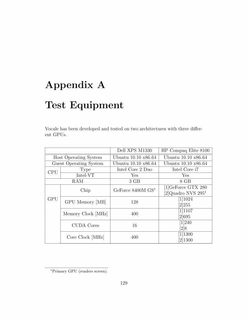
Appendix A
Test Equipment
Vocale has been developed and tested on two architectures with three differ-ent GPUs.
Dell XPS M1330 HP Compaq Elite 8100
Host Operating System Ubuntu 10.10 x86 64 Ubuntu 10.10 x86 64Guest Operating System Ubuntu 10.10 x86 64 Ubuntu 10.10 x86 64
CPUType Intel Core 2 Duo Intel Core i7
Intel-VT Yes YesRAM 3 GB 8 GB
GPU
Chip GeForce 8400M GS1 [1]GeForce GTX 280[2]Quadro NVS 2951
GPU Memory [MB] 128[1]1024[2]255
Memory Clock [MHz] 400[1]1107[2]695
CUDA Cores 16[1]240[2]8
Core Clock [MHz] 400[1]1300[2]1300
1Primary GPU (renders screen).
129
Appendix B
Virtio Performance
These measurements show the performance of virtio-serial, a virtualhardware device integrated in Qemu. The plots show the bandwidth as afunction of the transfer size. The transparent area shows the standard devi-ation of the test results.
130
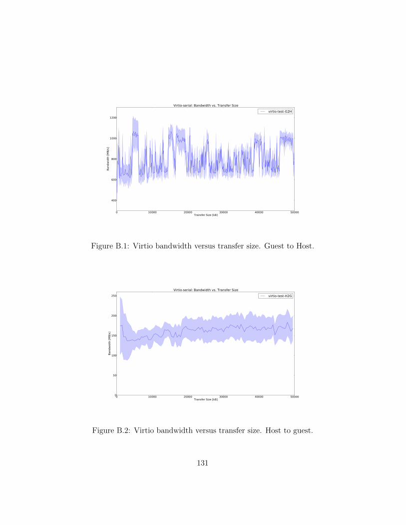
0 10000 20000 30000 40000 50000Transfer Size [kB]
400
600
800
1000
1200
Band
wid
th [M
B/s]
Virtio-serial: Bandwidth vs. Transfer Sizevirtio-test-G2H
Figure B.1: Virtio bandwidth versus transfer size. Guest to Host.
0 10000 20000 30000 40000 50000Transfer Size [kB]
0
50
100
150
200
250
Band
wid
th [M
B/s]
Virtio-serial: Bandwidth vs. Transfer Sizevirtio-test-H2G
Figure B.2: Virtio bandwidth versus transfer size. Host to guest.
131