Embed Size (px)
Citation preview
GPS module GNS 2201 Datasheet preliminary specification
© GNS-GmbH 2014
V 1.1, Oct 24th 2014
1
1 INTRODUCTION
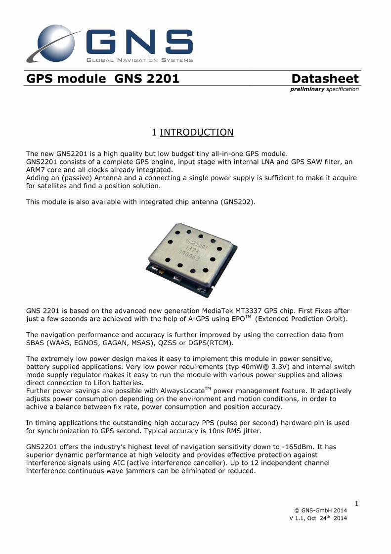
The new GNS2201 is a high quality but low budget tiny all-in-one GPS module.
GNS2201 consists of a complete GPS engine, input stage with internal LNA and GPS SAW filter, an
ARM7 core and all clocks already integrated.
Adding an (passive) Antenna and a connecting a single power supply is sufficient to make it acquire
for satellites and find a position solution.
This module is also available with integrated chip antenna (GNS202).
GNS 2201 is based on the advanced new generation MediaTek MT3337 GPS chip. First Fixes after
just a few seconds are achieved with the help of A-GPS using EPOTM (Extended Prediction Orbit).
The navigation performance and accuracy is further improved by using the correction data from
SBAS (WAAS, EGNOS, GAGAN, MSAS), QZSS or DGPS(RTCM).
The extremely low power design makes it easy to implement this module in power sensitive,
battery supplied applications. Very low power requirements (typ 40mW@ 3.3V) and internal switch
mode supply regulator makes it easy to run the module with various power supplies and allows
direct connection to LiIon batteries.
Further power savings are possible with AlwaysLocateTM power management feature. It adaptively
adjusts power consumption depending on the environment and motion conditions, in order to
achive a balance between fix rate, power consumption and position accuracy.
In timing applications the outstanding high accuracy PPS (pulse per second) hardware pin is used
for synchronization to GPS second. Typical accuracy is 10ns RMS jitter.
GNS2201 offers the industry’s highest level of navigation sensitivity down to -165dBm. It has
superior dynamic performance at high velocity and provides effective protection against
interference signals using AIC (active interference canceller). Up to 12 independent channel
interference continuous wave jammers can be eliminated or reduced.
GPS module GNS 2201 Datasheet preliminary specification
© GNS-GmbH 2014
V 1.1, Oct 24th 2014
2
Features
• 66 acquisition-/ 22 tracking channels
• Ultra high tracking/navigation sensitivity: -165dBm
• Extremely fast TTFF at low signal level
• QZSS, SBAS (WAAS,EGNOS,MSAS,GAGAN) or DGPS(RTCM) correction support
• A-GPS by EPO “Extended Prediction Orbit” TM enables 7/14days prediction
• 12 Multitone Active Interference Canceller (AIC) for GPS-in-band jammer rejection
• AlwaysLocate TM : Intelligent Algorithm for power saving
• High accuracy 1PPS output
• NMEA-0183 or binary protocol
• Embedded mini logger function (internal NV RAM of 8kB stores up to ~500 datasamples)
• High update rate (up to 5/s)
• GPS consumption current(@3.3V):
Acquisition: 15mA typical
Tracking: 12mA typical
• Low backup current consumption 8uA, typical
• Small form factor: 10x9.3x2.0 mm
Applications
Navigation
o In-vehicle Navigation equipment
o Dynamic Navigation
o Portable (“nomadic”) devices
o Netbooks, tablet PCs and mobile phones
Timing
o Precision timing via GPS
Location based applications
o GPS Tracker
o Security devices
o Camera equipment
o Geofencing
o Infrastructure applications
GPS module GNS 2201 Datasheet preliminary specification
© GNS-GmbH 2014
V 1.1, Oct 24th 2014
3
2 INDEX
1 INTRODUCTION ----------------------------------------------------------------------------------------- 1 2 INDEX --------------------------------------------------------------------------------------------------- 3 3 FUNCTIONAL DESCRIPTION ---------------------------------------------------------------------------- 4
3.1 Block diagram -------------------------------------------------------------------------------------------------------------- 4 3.2 System description --------------------------------------------------------------------------------------------------------- 4 3.3 Power Management Features ---------------------------------------------------------------------------------------------- 5 3.4 Active interference cancellation (AIC) ------------------------------------------------------------------------------------ 7 3.5 AGPS with EPOTM data ------------------------------------------------------------------------------------------------------ 7 3.6 Pulse Per Second (PPS) ---------------------------------------------------------------------------------------------------- 8 3.7 SBAS (Satellite Based Augmentation) support --------------------------------------------------------------------------- 9 3.8 DGPS (Differential GPS) support ------------------------------------------------------------------------------------------ 9 3.9 Real time clock (RTC) ------------------------------------------------------------------------------------------------------ 9 3.10 UART interface -------------------------------------------------------------------------------------------------------------- 9 3.11 Module default settings -------------------------------------------------------------------------------------------------- 10
4 TYPICAL APPLICATION BLOCK DIAGRAM ------------------------------------------------------------ 11 4.1 Typical System overview ------------------------------------------------------------------------------------------------- 11
5 GPS characteristics ----------------------------------------------------------------------------------- 12 5.1 GPS characteristics ------------------------------------------------------------------------------------------------------- 12
6 DESIGN GUIDELINES --------------------------------------------------------------------------------- 13 6.1 General -------------------------------------------------------------------------------------------------------------------- 13 6.2 GPS antenna -------------------------------------------------------------------------------------------------------------- 13
7 ELECTRICAL SPECIFICATION ------------------------------------------------------------------------- 14 7.1 Absolute Maximum Ratings ---------------------------------------------------------------------------------------------- 14 7.2 Recommended Operating Conditions ----------------------------------------------------------------------------------- 14
8 DEVICE PINOUT DIAGRAM --------------------------------------------------------------------------- 15 8.1 Pin configuration --------------------------------------------------------------------------------------------------------- 15 8.2 Pin assignment ----------------------------------------------------------------------------------------------------------- 16
9 NMEA DATA interface --------------------------------------------------------------------------------- 17 9.1 NMEA command interface------------------------------------------------------------------------------------------------ 17
10 PHYSICAL DIMENSIONS ----------------------------------------------------------------------------- 18 11 RECOMMENDED PAD LAYOUT ----------------------------------------------------------------------- 19 12 MATERIAL INFORMATION --------------------------------------------------------------------------- 19 13 RECOMMENDED SOLDERING REFLOW PROFILE --------------------------------------------------- 20 14 PACKAGE INFORMATION ---------------------------------------------------------------------------- 21 15 TAPE&REEL INFORMATION -------------------------------------------------------------------------- 21 16 REEL INFORMATION --------------------------------------------------------------------------------- 22 17 ORDERING INFORMATION -------------------------------------------------------------------------- 23 18 ENVIRONMENTAL INFORMATION ------------------------------------------------------------------- 23 19 MOISTURE SENSITIVITY ---------------------------------------------------------------------------- 24 20 DOCUMENT REVISION HISTORY -------------------------------------------------------------------- 24 21 RELATED DOCUMENTS ------------------------------------------------------------------------------ 24

GPS module GNS 2201 Datasheet preliminary specification
© GNS-GmbH 2014
V 1.1, Oct 24th 2014
4
3 FUNCTIONAL DESCRIPTION
3.1 Block diagram
3.2 System description
The GNS2201 core is a high performance, low power GPS receiver that includes an integrated RF
frontend.
Due to high input sensitivity it can work directly with a passive antenna.
GNS2201 is a complete GPS engine, including:
- Full GPS processing without any host processing requirements
- Standard NMEA message output
- A powerful command and control interface
- All clock sources integrated on module
- RF frontend for direct connection of passive or active antennas
- Interfaces for DGPS, PPS, Fix Status Indicator
GPS chip
32.768kHz crystal
26.0MHz TCXO
SAW filter
GND 4,E1,E2
5 RF In
1PPS 13
8 3D-Fix
11
10
RXDB
TXDA
9 RXDA
VCC 16
15 VBackup
3 RESET
Wakeup
6

GPS module GNS 2201 Datasheet preliminary specification
© GNS-GmbH 2014
V 1.1, Oct 24th 2014
5
3.3 Power Management Features
GNS2201 provides full power operation at very low power budget. Further improvement is possible
by activating the integrated power saving features.
Selectable Power management features:
In Standby mode RF frontend and internal MPU are switched to deep sleep state. Power
consumption is reduced to 0.6 mW (200µA).This state can be entered by sending the NMEA
command: $PMTK161,0*28<CR><LF>.
Leaving standby mode and resuming to normal operation will be managed by sending any
byte to the module.

GPS module GNS 2201 Datasheet preliminary specification
© GNS-GmbH 2014
V 1.1, Oct 24th 2014
6
Periodic mode describes a power mode, which will autonomously power on/off the module
in programmable time slots with reduced fix rate. Periodic mode is useful during stationary
operation or if position fixes are just needed from time to time. Since power consumption in
GPS off times is nearly zero, the power consumption in periodic mode can be estimated by
Ptracking * (ton/(ton+toff)).
Periodic mode is controlled with NMEA command $PTMK225. See document
NMEA_Interface_manual_MTK_Vx for programming details.
AlwaysLocateTM feature provides an optimized overall GPS system power consumption in
tracking mode under open sky conditions. Always Locate is an intelligent control of periodic
mode. Depending on the environment and motion conditions, GNS2201 can adjust the
on/off time to achieve balance of positioning accuracy and power consumption. The best
power saving will be made under good reception in stationary mode. Critical reception
conditions and dynamic movements will need full activity of the GPS engine which causes
nominal power requirements (12mA typ in tracking mode).

GPS module GNS 2201 Datasheet preliminary specification
© GNS-GmbH 2014
V 1.1, Oct 24th 2014
7
3.4 Logger function
GNS202 provides an autonomous logger function that automatically stores position information in
an internal 8kB NVRam memory. This small memory portion allows 500 position measurements to
be stored.
A complete tracking unit can be realized without any external CPU or memory.
The parameters for logging are programmable via the NMEA command interface. The following
parameter can be set to optimize logging time:
- logger rate
The commands for logger include:
- start logging
- stop logging
- erase memory
- readout memory
please refer to the GPS NMEA_Interface_manual_MTK_V for details.
3.5 Active interference cancellation (AIC)
Because different wireless technologies like Wi-Fi, GSM/GPRS, 3G/4G, Bluetooth are integrated into
portable systems, the harmonic of RF signals may influence the GPS reception.
The multi-tone active interference canceller can reject external RF interference which come from
other active components on the main board, thus improving the performance of GPS reception.
GNS2201 can cancel up to 12 independent continuous wave (CW) channels having signal levels of
up to -80dBm. The functionality is enabled by default and increases power consumption by about
1mA.
3.6 AGPS with EPOTM data
AGPS (assisted GPS) allows to shorten TTFF (TimeToFirstFix) by injecting ephemeris data from an
external source into the module’s memory. With the help of these data, the module does not need
to acquire satellite positions by receiving the data from the satellites.
Depending on time and position information that is still available in the module memory, the TTFF
can be reduced to just a few seconds.
The GNS AGPS service is based on a short term predicted data service. The predicted data will be
fully processed by the GPS engine, the host must load the data from the web and transfer them
over the UART to the module:
1. Check GNS2201 module EPO data for validity by comparing the time. (time parameters for
existing 2201 data can be retrieved through a NMEA command)
2. Connect to web server through network connection (GPRS, WLAN, LAN,..)
3. Download file. There are just two files, covering all GPS satellites. The first file (MTK7d.EPO)
is for 7 days (53kB), the other is 106Kbytes for 14 days (MTK14d.EPO)
4. “Parse” file, using software example. This is quite easy, there must be added some header
bytes and a checksum and a control counter. GNS offers software support on this.
Internal Logger Function
Min Typ max unit
Logger data rate 1/15 1 1/s
Logger data memory 8 kBytes Flash memory

GPS module GNS 2201 Datasheet preliminary specification
© GNS-GmbH 2014
V 1.1, Oct 24th 2014
8
5. Download to GNS2201 module. please refer to the NMEA_Interface_manual_MTK_Vx for
details
If the host has low memory available, there’s no need to save the whole file. The steps 3..5 can be
done frame by frame needing less than 2kBytes of buffer memory.
Code samples and support for several platforms are available from GNS (in preparation)
Thanks to the predicted system, download data stay valid for up to 14 days. Therefore, users can
initiate the download everytime and benefit from using (W)LAN instead of using expensive GSM.
File size will be ~50kBytes for a one week prediction data set.
AGPS characteristics
System 6hrs predicted data
File size for data download 53 kB 1 week prediction data
Maximum prediction time 7 14 days
TTFF 1 sec Time and last position available
TTFF 15 sec Last position available
3.7 Pulse Per Second (PPS)
GNS2201 provides a Pulse Per Second (PPS) hardware output pin for timing purposes. After
calculation of a 3D position fix (default setting), the PPS signal is accurately aligned to the GPS
second boundaries. The pulse generated is approximately 100 milliseconds in duration and the
repetition rate is 1 second. On request PPS output can activated on a 2D- fix or after power-up of
the module, providing a time accuracy decreased PPS signal.
GNS2201 module provides an exceptionally low RMS jitter of typical 10 nanoseconds.
PPS characteristics based upon a 3D-fix
1PPS pulse duration - 100 - msec
1PPS time jitter - 10
nsec
RMS
Pulse rising edge deviation from expected pulse time, measured with full 3D fix
1PPS rise and fall time 5 nsec 10%..90%, load is 10k||5pF
T1
T2
T1 = 100ms T2 = 1sec

GPS module GNS 2201 Datasheet preliminary specification
© GNS-GmbH 2014
V 1.1, Oct 24th 2014
9
3.8 SBAS (Satellite Based Augmentation) support
GNS2201 supports Satellite Based Augmentation for improvement of the navigation precision.
Correction data is sent from geostationary satellites to the GPS receiver. GNS2201 supports
European, US, and Asian augmentation systems (EGNOS, WAAS, QZSS, GAGAN, MSAS) to enable
precision improvements in nearly every region of the world.
SBAS is active by default and will automatically track the available SBAS satellites. It can be
disabled by NMEA command. See document NMEA_Interface_manual_MTK_Vx for details.
3.9 GPS almanac and ephemeris data
For quick re-acquisition of the GPS receiver after off-times, the GPS engine should have access to
almanac and ephemeris data. This data is permanently stored inside GNS2201 module, even if all
power supplies have been removed. When the receiver is powered-up again, the data will be used
to allow a quick re-acquisition, as soon as a coarse time information is available. Time will be
available immediately, when RTC is kept running.
3.10 DGPS (Differential GPS) support
GNS2201 accepts DGPS input in RTCM format. DGPS provides precision position fixes down to
centimetres and is used in professional applications like agriculture. The second UART (UART_B) of
the module is used to feed the data in. DGPS is deactivated by default. For configuration of the
UART port, some NMEA commands must be implemented. See NMEA_Interface_manual_MTK_Vx
document for details.
Note : Since SBAS and DGPS both do (different) corrections on the fix position solution, they
cannot be used at the same time! SBAS / DGPS usage is programmed through the NMEA Interface.
3.11 Real time clock (RTC)
GNS2201 has a real time clock with 32,768Hz crystal onboard. As long as VBACKUP is connected to
a power source, the real time clock and the module memory can be kept alive at very low power
consumption of just 7uA. The RTC will track the current time and enable the module to start from
sleep states with very fast time to first Fix (TTFF).
3.12 UART interface
GNS2201 core and I/O sections work at 3.3V nominal. Absolute Maximum Ratings should not be
exceeded. Should the GNS2201 be interfaced to a host with I/O at higher/lower levels, level
shifters should be used. UART baud rate is 9600baud by default. The baud rate can be modified to
higher rates by a NMEA software command. See NMEA_Interface_manual_MTK_Vx document for
details.
GPS UART Default Settings Parameter Value
Baud rate 9600
Data length 8 bits
Stop bit 1
Parity None

GPS module GNS 2201 Datasheet preliminary specification
© GNS-GmbH 2014
V 1.1, Oct 24th 2014
10
3.13 Module default settings
The GNS2201 module comes with default settings, which are persistently programmed. Whenever
power is removed from the module (both Vcc and VBACKUP), the settings will be reset to the
values shown in the following table.
Default settings interface
UART setting 9600,8,N,1
Fix frequency (update rate) 1/sec
NMEA sentences $GPRMC,$GNGSA,$GPGSV,$GPGGA
NMEA rate Once a second: RMC,GSA,VTG ,GSV
navigation
Active interference cancellation:MTAIC
enabled
Fix interval 1 sec
DGPS option SBAS enabled
Datum WGS 84
PPS pulse output length 100ms
Fix interval 1 sec
Fix LED 100ms on time 900ms off time
Static navigation Disabled
Datum WGS84
DGPS SBAS, enabled
Initial position output Lat.:90° Lon. : 0°
QZSS,EPO Enabled
Logger
Logger mode Overlap (memory handlesd as a ring buffer, overwrite if full)
Content Basic (UTC, position)
Memory Internal 8k NV RAM
Memory size 8kB (500 datasamples)
Mode Logging if fix available and movement >50m
GPS module GNS 2201 Datasheet preliminary specification
© GNS-GmbH 2014
V 1.1, Oct 24th 2014
11
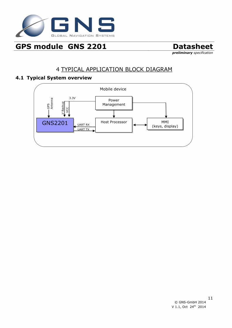
4 TYPICAL APPLICATION BLOCK DIAGRAM
4.1 Typical System overview
Mobile device
Host Processor MMI (keys, display)
Power Management
3.3V
GNS2201
GPS
Ante
nna
UART RX
UART TX
VC
C
V B
ackup

GPS module GNS 2201 Datasheet preliminary specification
© GNS-GmbH 2014
V 1.1, Oct 24th 2014
12
5 GPS characteristics
5.1 GPS characteristics
Parameter Min Typ Max Unit Note general
Frequency 1575.42 MHz GPS L1
Datum WGS84
SV Numbers GPS #1~32
DGPS
SBAS[QZSS,WAAS,EGNOS, MSAS,GAGAN], RTCM
AGPS
Internal processing of predicted orbit data. Service available via ftp. 6hrs prediction interval
Output data frequency 1/1000 1 10 1/sec Configurable
Navigation&tracking sensitivity -165 -167 dBm
Acquisition sensitivity -148 dBm autonomous
TTFF hotstart <1 sec All SVs @-130dBm
TTFF autonomous cold start 34 sec All SVs @-130dBm
Number of channels tracking 22
Number of acquisition channels 66
Dimension 10x9.3x2.0 mm3 Tolerance is 0.2 mm
Weight 0.41 g
Power consumption
acquisition 15.3* mA
NMEA frequency = 1/sec*,SBAS enabled, MTAIC enabled, Vdd = 3.3V
tracking 11.9* mA
NMEA frequency = 1/sec*, SBAS enabled, MTAIC enabled, Vdd=3.3V
Backup current @ 3V 8 μA *note: further power savings are possible using AlwaysLocate or periodical modes. Actual possible savings depend on use cases.
Accuracy
Position error CEP50 - 3 - m Without aid
Position error CEP50 - 2.5 - m Using (SBAS)
Velocity error - 0.1 - m/s Without aid
velocity error - 0.05 - m/s Using (SBAS)
ITAR limits
Operation altitude - 18,000 m
Operation velocity - - 515 m/s
Operation acceleration - - 4 G

GPS module GNS 2201 Datasheet preliminary specification
© GNS-GmbH 2014
V 1.1, Oct 24th 2014
13
6 DESIGN GUIDELINES
6.1 General
Although GNS2201 GPS module provides best performance at low power consumption, special care
should be taken to provide clean signal and clean power supplies. A multi layer carrier board with
solid power- and ground planes is recommended. Power lines should be blocked near to the module
with low ESR capacitors.
Radiated noise from neighbour components may also reduce the performance of the module.Special
care must be taken when designing the RF input tracks and antenna connection.
Generally the rules for good and low noise design should be followed:
Use a solid ground plane, best on layer 2 of the mainboard
Keep noisy components (µC, switch mode supplies) as far as possible away from sensitive
antenna inputs
Place decoupling capacitors near to the source of noise and provide a short and low
induction connection to ground (use multi-vias if needed)
EMC filters or noise filtering coils or beads can help to reduce the noise level further.
Select system clocks in a way, that no harmonics will match the GPS frequency of 1575.42
MHz
6.2 GPS antenna
GNS2201 contains all input circuitry needed to connect a passive GNS antenna directly.
If there is a long wire between GNS2201 RF input and antenna, there should be an LNA (on the
antenna side) to compensate for cable losses ("active" antenna).
More information about connecting and implementing a GPS antenna to an application PCB, please
refer to GPS Antenna Design Guide.pdf.

GPS module GNS 2201 Datasheet preliminary specification
© GNS-GmbH 2014
V 1.1, Oct 24th 2014
14
7 ELECTRICAL SPECIFICATION
7.1 Absolute Maximum Ratings Parameter Value Unit
Supply voltage: Vcc –0.5 to 4.3 V
Backup voltage: VBACKUP –0.5 to 4.3 V
Input voltage to analog pins –0.5 to 3.3 V
Input voltage to all other pins –0.5 to Vcc V
Operating ambient temperature range –40 to +85 °C
Storage temperature range –50 to +125 °C
7.2 Recommended Operating Conditions
Parameter Min Typ Max Unit Note Vcc 2.8 3.3 4.3 V supply voltage
Vcc ripple voltage 50 mVpp
VBACKUP 2.0 3.0 4.3 V
Backup voltage for RTC and memory retention, must be available during normal operation
High level output voltage VOH 0.8 * Vcc Vcc V
Low level output voltage VOL
0 0.2*Vcc V
High-level input voltage VIH 0.80* Vcc Vcc V
Low-level input voltage VIL 0 0.2* Vcc V
Operating temperature -40 85 °C Full specified sensitivity

GPS module GNS 2201 Datasheet preliminary specification
© GNS-GmbH 2014
V 1.1, Oct 24th 2014
15
8 DEVICE PINOUT DIAGRAM
8.1 Pin configuration
(TOP view)

GPS module GNS 2201 Datasheet preliminary specification
© GNS-GmbH 2014
V 1.1, Oct 24th 2014
16
8.2 Pin assignment
Pin Name I/O Description & Note
1 NC Not conected
2 NC Not conected
3 RESET I System reset pin An external reset applied to this pin overrides all other internal controls. RESET# is an active low signal. Pulling
this pin low for at least 20 μs causes a system reset. 4 RF_GND A RF Ground
Ground connection of antenna should be connected at this pin.
5 RF_IN A RF input connection forGPS antenna. Supports passive antenna.
6 WAKEUP I Wakeup input This pin indicates activity of the GPS and can be used to activate GPS module
7 NC Not conected
8 3D_FIX O 3D-Fix Indicator The 3D_FIX is assigned as a fix flag output. If not used, keep floating.
Before 2D Fix The pin will be low
After 2D or 3D Fix The pin will toggle between high and low at a frequency of 1/s
This pin must not be connected to high-level at power-on sequence.
9 RXA I Serial Data Input A for Firmware update 1. This is the UART-A receiver of the module. It is used to receive commands from system
10 TXA O Serial Data Output A for NMEA output This is the UART-A transmitter of the module. It outputs GPS information for application.
11 RXB I Serial Data Input B This is the UART-B receiver of the module. It is used to receive RTCM data from system
12 NC Not conected
13 1PPS O 1PPS Time Mark Output 2.8V CMOS Level This pin provides one pulse-per-second output from the module and synchronizes to GPS time. Keep floating if not used.
14 NC Not conected
15 VBACKUP P Backup power input for RTC & navigation data keep This connects to the backup power of the GPS module. Power source (such as battery) connected to this pin will
help the GPS chipset in keeping its internal RTC running when the main power source is turned off. The voltage should be kept between 2.8V~4.3V, Typical 3.3V.
If VBACKUP power was not reserved, the GPS receiver will perform a lengthy cold start every time it is powered-
on because previous satellite information is not retained and needs to be re-transmitted.
This pin must be connected for normal operation. 16 VCC P Main DC power input
The main DC power supply for the module. The voltage should be kept between from 2.8V to 4.3V. The ripple
must be limited under 50mVpp (Typical: 3.3V). E1 GND P Ground
E2 GND P Ground
(1) I = INPUT; O = OUTPUT; I/O = BIDIRECTIONAL; P = POWER PIN; ANA = ANALOG PIN.

GPS module GNS 2201 Datasheet preliminary specification
© GNS-GmbH 2014
V 1.1, Oct 24th 2014
17
9 NMEA DATA interface
GNS2201 provides NMEA (National Marine Electronics Association) 0183 compatible data.
A set of proprietary NMEA commands are available to send control messages to the module.
These commands are described in a separate document: NMEA_Interface_manual_MTK_Vx manual.
For standard operation, no commands are needed; the module will start outputting NMEA sentences
after power supply has been attached. GNS2201 will always start communication output with 9600
bit per second.
If non standard options are needed (f.e. other baud rate , other NMEA sequence) they can be
programmed from host controller during runtime.
Important note : options set by using NMEA command interface are not persistent! They will be lost
when power is removed. A backup supply at VBACKUP will be sufficient to keep them.
9.1 NMEA output sentences
NMEA output sentences Type content RMC Recommended Minimum Navigation Information
GGA Fix Data, Time, Position and fix related data
GSA DOP and active satellites
GSV Satellites in view
Refer to NMEA_Interface_manual_MTK_Vx document for more information.
9.2 NMEA command interface
GNS2201 NMEA command interface allows to control settings and the extended functions. The
command interface specification is available in an extra document:
NMEA_Interface_manual_MTK_Vx manual.
Two groups of commands are available:
Setting commands do modify the behavior of the module.
Note : modified settings will be valid as long as the module is powered through Vcc or VBACKUP.
(f.e. : setting of a new baud rate). After removing Vcc and VBACKUP, all settings are reset to their
default values.
Action commands will perform the specified action one time after the command has been received.
(f.e. : request for cold start)
Commands are always started with $PTMK, directly followed by the command number 000..999.
Each command must be terminated by *<chksum>and a <CR><LF>.
The checksum calculation is simple, just XOR all the bytes between the $ and the * (not including
the delimiters themselves). Then use the hexadecimal ASCII format.

GPS module GNS 2201 Datasheet preliminary specification
© GNS-GmbH 2014
V 1.1, Oct 24th 2014
18
10 PHYSICAL DIMENSIONS
TOP VIEW
all units in mm, tolerance is ±0.2mm
4.1
0.625
1.25
5.0
10
9.3
1.25=pad grid
3.7
25
4.6
5
2.1
1.2
pads 0.85*1.15
pads 2.25*2.25 1.2
5

GPS module GNS 2201 Datasheet preliminary specification
© GNS-GmbH 2014
V 1.1, Oct 24th 2014
19
11 RECOMMENDED PAD LAYOUT
TOP VIEW all units in mm
12 MATERIAL INFORMATION
Complies to ROHS standard
ROHS documentations are available on request
Contact surface: gold over nickel
0.625
1.25
10.0
1.25=pad grid
4.2
75
5.0
16 pads
0.95*1.55
2 pads
2.85*2.65
1.2
5
3.95

GPS module GNS 2201 Datasheet preliminary specification
© GNS-GmbH 2014
V 1.1, Oct 24th 2014
20
13 RECOMMENDED SOLDERING REFLOW PROFILE
Notes: 1. GNS2201 should be soldered in upright soldering position. In case of head-over soldering, please prevent shielding / GNS2201 Module from falling down. 2. Do never exceed maximum peak temperature
3. Reflow cycles allowed : 1 time 4. Do not solder with Pb-Sn or other solder containing lead (Pb) 5. This device is not applicable for flow solder processing 6. This device is not applicable for solder iron process
100
200
300
t[sec] 100 200
T[°C]
250°C max
250°C for 10 sec max
230°C for 40 sec max
160°C 190°C 120 sec reflow solder

GPS module GNS 2201 Datasheet preliminary specification
© GNS-GmbH 2014
V 1.1, Oct 24th 2014
21
14 PACKAGE INFORMATION
The GNS2201 are placed on a tray for quantities below 100 pieces. The trays will be stacked and
packed together.The trays are placed inside an antistatic bag.
15 TAPE&REEL INFORMATION
Tape information:

GPS module GNS 2201 Datasheet preliminary specification
© GNS-GmbH 2014
V 1.1, Oct 24th 2014
22
16 REEL INFORMATION
:
Number of devices: 2000pcs/reel

GPS module GNS 2201 Datasheet preliminary specification
© GNS-GmbH 2014
V 1.1, Oct 24th 2014
23
17 ORDERING INFORMATION
Ordering information Type Part# laser marking Description
GNS2201 4037735105287
GNS2201 GPS module
18 ENVIRONMENTAL INFORMATION
This product is free of environmental hazardous substances and complies with 2002/95/EC. (RoHS
directive).
Type
datecode/
subversion serial#

GPS module GNS 2201 Datasheet preliminary specification
© GNS-GmbH 2014
V 1.1, Oct 24th 2014
24
19 MOISTURE SENSITIVITY
This device must be prebaked before being put to reflow solder process.
Disregarding may cause destructive effects like chip cracking, which leaves the device defective !
Shelf life 6 months , sealed
Possible prebake recommendations 12 hrs @ 60°C
Floor life (time from prebake to solder process) <72 hrs
20 DOCUMENT REVISION HISTORY
V01 Aug 1st 2014 P.Skaliks initial preliminary
V11 Oct 24th 2014 P.Skaliks General review, many corrections
21 RELATED DOCUMENTS
title Description / file Available from
GPS Antenna Connection Design
Guide
Design Guide to implement an GPS
antenna to an application PCB
www.forum.gns-gmbh.com www.gns-gmbh.com
NMEA_Interface_manual_MTK_Vx Detailed description of NMEA
commands
www.forum.gns-gmbh.com www.gns-gmbh.com
GNS2201 StarterKit user manual User manual for the GNS2201 receiver
based evaluation kit
www.forum.gns-gmbh.com www.gns-gmbh.com
GNS GMBH 2014
THE INFORMATION IN THIS DOCUMENTATION DOES NOT FORM ANY QUOTATION OR CONTRACT. TECHNICAL DATA ARE DUE TO BE CHANGED WITHOUT
NOTICE. NO LIABILITY WILL BE ACCEPTED BY THE PUBLISHER FOR ANY CONSEQUENCE OF THIS DOCUMENT'S USE. REPRODUCTION IN WHOLE OR IN PART IS PROHIBITED WITHOUT THE PRIOR WRITTEN CONSENT OF THE COPYRIGHT OWNER