Embed Size (px)
Citation preview

Instruction Manual
GPS ii

2 PowerBox-Systems − World Leaders in RC Power Supply Systems
Dear customer,
we are delighted that you have decided to purchase the GPS ll from our range. We hope you have many hours of pleasure and great success with your new GPS ll.
1. PRODUCT DESCRIPTION
The GPS sensor was originally introduced to provide a means of speed-dependent gain adjustment for our iGyro, but the GPS II is an entirely new development, and can now be used with all current telemetry systems.
This latest generation of GPS receivers is extremely agile, and capable of mea-suring speed even when there are rapid changes in speed or direction. The radial helical aerial provides outstanding reception in any flight attitude, while the supple-mentary pre-amplifier improves reliability of reception under difficult conditions.
The GPS II module is a very compact unit which virtually any model can accommo-date. The integral LED provides information about receiver status.
It is possible to set up alarms, addresses and other parameters using the Power-Box USB interface and the free PowerBox Terminal program; the actual facilities vary according to the telemetry system in use. However, the USB interface function can also be carried out by the USB adapters made by Jeti or Multiplex.
Software updates can be loaded using the USB adapter, so there is nothing to pre-vent future expansion.
www.powerbox-systems.com 3
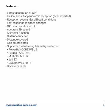
Features:
- Latest generation of GPS- Helical aerial for panoramic reception (even inverted)- Reception even under difficult conditions- Fast response to speed changes- GPS status indicator LED- Accurate 3D speed- Altimeter function- Distance function- Distance covered- Geo co-ordinates- Supports the following telemetry systems: • PowerBox CORE P²BUS • Futaba FASSTest • Multiplex M-Link • Jeti EX • Graupner/SJ HoTT- Update-capable

4 PowerBox-Systems − World Leaders in RC Power Supply Systems
2. CONNECTIONS
3. INITIAL STEPS, SETTING UP THE UNIT
By default the GPS II is set up to work with the iGyro and the M-Link telemetry sys-tem. If the GPS is required to work with a different telemetry system, it must first be set up to suit. This requires a USB interface and the Y-lead supplied in the set. The PowerBox USB lead can be used as USB interface, but USB adapters made by other manufacturers are also suitable. To date we have checked the following types: Multiplex and Jeti.
Download the PowerBox Terminal program from our website, and follow the instal-lation instructions. Use the following link to locate the program and the associated instructions:www.powerbox-systems.com/downloads/powerbox-terminal.html
Connect the GPS II to the USB adapter and a battery using the Y-lead. Any type of battery with a voltage in the range 4.8 – 8.4 V can be used.
Radial helical aerial
GPS status indicator
Patch-lead socket

www.powerbox-systems.com 5
The next step is to start the Terminal program:

6 PowerBox-Systems − World Leaders in RC Power Supply Systems
You have already completed steps 1 and 2; click on Continue at the bottom. A count-down now starts, while Terminal waits for the GPS II to switch to PC control; this screen now appears:
The first step here is to select the telemetry system you wish to use. The lower part of the screen displays various set-up facilities which vary according to the telemetry system you select.
The GPS configuration option is used to set up the GPS II for your intended pur-pose.
www.powerbox-systems.com 7
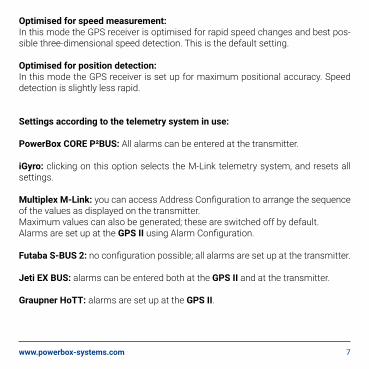
Optimised for speed measurement:In this mode the GPS receiver is optimised for rapid speed changes and best pos-sible three-dimensional speed detection. This is the default setting.
Optimised for position detection:In this mode the GPS receiver is set up for maximum positional accuracy. Speed detection is slightly less rapid.
Settings according to the telemetry system in use:
PowerBox CORE P²BUS: All alarms can be entered at the transmitter.
iGyro: clicking on this option selects the M-Link telemetry system, and resets all settings.
Multiplex M-Link: you can access Address Configuration to arrange the sequence of the values as displayed on the transmitter.Maximum values can also be generated; these are switched off by default.Alarms are set up at the GPS II using Alarm Configuration.
Futaba S-BUS 2: no configuration possible; all alarms are set up at the transmitter.
Jeti EX BUS: alarms can be entered both at the GPS II and at the transmitter.
Graupner HoTT: alarms are set up at the GPS II.

8 PowerBox-Systems − World Leaders in RC Power Supply Systems
4. INSTALLATION, CONNECTIONS
Since the GPS II features a radial aerial, it can be installed in any attitude. Ideally the aerial should face up or to one side. The only important point to observe when installing the unit is that there should be no shielding materials in the vicinity, as large areas of carbon fibre or metal have an adverse effect on reception.If it is not possible to install the unit close to the iGyro or receiver, the patch-lead can be extended. Lengths up to 2.0 m present no problem.
Connecting the different systems:
PowerBox CORE P²BUS: this system is set by default
Multiplex M-Link: Connect the sensor directly to the receiver’s Telemetry input. Multiple sensors can be connected using a Y-lead.
Futaba S-BUS2: Connect the sensor directly to the receiver’s S-BUS2 input. Multip-le sensors can be connected using a Y-lead. The sensor must first be connected to the transmitter for registration. The registration process is described in our Expert Forum.
Jeti EX: Connect the sensor directly to the receiver’s EXT input. If you wish to connect multiple sensors, you will need an “Expander E4 EX”. The data to be dis-played is selected at the transmitter.
Graupner/SJ HoTT: Connect the sensor directly to the receiver’s Telemetry input. Multiple sensors can be connected using a Y-lead.

www.powerbox-systems.com 9
5. THE UNIT IN USE
We deliberately decided against using a buffer battery with the GPS II to store the last satellite data, as we wished to avoid the wear associated with this. This means that the GPS II has to seek and locate the satellites every time it is switched on. The process takes 30 to max. 60 seconds, but this does not present any problem, as it usually takes much longer than this to prepare a model for flight between switching on and taking off.The status of what is known as the “FIX” is indicated by the integral LED: if the LED flashes, this indicates that the receiver is seeking satellites; a continuously lit LED indicates that the GPS is ready for use.
6. UPDATING
If new functions become available, or improvements are made to the performance of the GPS II, these can be loaded in just a few minutes by means of a software update. Once again this requires PowerBox Terminal and a USB interface.Start the Terminal program, and select the GPS II at the top of the screen. Wait ten se-conds, then briefly click the Software Update button. The Continue button now appears at the bottom of the screen; click on this.
Two options are now availa-ble:

10 PowerBox-Systems − World Leaders in RC Power Supply Systems
Online Update: ideally the computer should be connected to the Internet. The On-line Update function now automatically loads the most recent file from our server.
Select file: installing PowerBox Terminal copies the Update files onto the compu-ter. You will find the file using this path:
C:\PowerBox Terminal\Programm\update\
This means that the software can be updated without an Internet connection, al-though this file is only as up-to-date as the time when the Terminal program was installed.
Once the correct file is located, click on: Carry out update nowThe GPS II is ready for use again when the status indictor reaches 100%.
7. INFORMATION ON ACCURACY
There is a widespread belief that GPS cannot measure speed accurately in three-di-mensional space, but this is not so. The GPS II employs the latest generation of receivers which measure speed by exploiting the Doppler effect, rather than by comparing the current position with the previous one. This measurement process is fast and very accurate.
The positional accuracy of a GPS system is subject to the usual fluctuations, and even the latest receivers have not improved on this aspect of performance. Howe-ver, the error is generally less than 10 m, and is therewith negligible for modelling applications.

www.powerbox-systems.com 11
10. SERVICE NOTE
We are anxious to offer good service to our customers, and to this end we have set up a Support Forum which deals with all queries concerning our products. This relieves us of a great deal of work, as it eliminates the need to answer frequently asked questions time and again. At the same it gives you the opportunity to obtain help quickly all round the clock - even at weekends. All the answers are provided by the PowerBox Team, guaranteeing that the information is correct.
Please use the Support Forum before you telephone us.
You can find the forum at the following address:www.forum.powerbox-systems.com
8. SPECIFICATION
Max. horizontal speed: 1200 km/hMax. vertical speed: 360 km/hOperating voltage: 4.0 – 9.0 VCurrent drain: max. 60 mAWeight: 14 g incl. patch-leadsDimensions: 58 x 18 x 17 mm
9. SET CONTENTS
- GPS II- Patch-lead, 24 cm
- Self-adhesive pad- Operating instructions

12 PowerBox-Systems − World Leaders in RC Power Supply Systems
SERVICE ADDRESS
PowerBox-Systems GmbHLudwig-Auer-Straße 5D-86609 DonauwoerthGermany
11. GUARANTEE CONDITIONS
At PowerBox-Systems we insist on the highest possible quality standards in the development and manufacture of our products. They are guaranteed “Made in Germany”!
That is why we are able to grant a 36 month guarantee on our GPS ll from the initial date of purchase. The guarantee covers proven material faults, which will be corrected by us at no charge to you. As a precautionary measure, we are obliged to point out that we reserve the right to replace the unit if we deem the repair to be economically unviable.
Repairs which our Service department carries out for you do not extend the original guarantee period.
The guarantee does not cover damage caused by incorrect usage, e.g. reverse polarity, excessive vibration, excessive voltage, damp, fuel, and short-circuits. The same applies to defects due to severe wear.
We accept no liability for transit dama-ge or loss of your shipment. If you wish to make a claim under guarantee, please send the device to the following address, together with proof of purchase and a de-scription of the defect:

www.powerbox-systems.com 13
12. LIABILITY EXCLUSION
We are not in a position to ensure that you observe our instructions regarding in-stallation of the GPS ll, fulfil the recommended conditions when using the unit, or maintain the entire radio control system competently.
For this reason we deny liability for loss, damage or costs which arise due to the use or operation of the GPS ll, or which are connected with such use in any way. Regardless of the legal arguments employed, our obligation to pay compensation is limited to the invoice total of our products which were involved in the event, inso-far as this is deemed legally permissible.
We wish you every success with your new GPS ll.
Donauwoerth, february 2020

PowerBox-Systems GmbHcertified according to DIN EN ISO 9001
Ludwig-Auer-Straße 5D-86609 DonauwoerthGermany
+49-906-99 99 9-200 +49-906-99 99 9-209
www.powerbox-systems.com
02/2020


![Opcon Powerbox Folder[1]](https://img.dokumen.tips/doc/110x75/54f7af6e4a79597b198b471b/opcon-powerbox-folder1.jpg)