Embed Size (px)
Citation preview

GPRS ADAPTER
INSTALLATION AND USER MANUAL
for module version v2.45 and higher

2
Table of contents
1 Main function of the Adapter........................................................................................3 2 System operation ........................................................................................................3
2.1 Transmission through GPRS ..............................................................................4 2.1.1 Router settings ...........................................................................................4
Transmission in...................................................................................................5 2.2 reserve GPRS mode...........................................................................................5
2.2.1 Setup „GPRS_COM.exe” ...........................................................................6 2.3 Transmission when GPRS connection fails ........................................................7
3 Monitoring software settings........................................................................................8 3.1 Setting serial port connection..............................................................................8 3.2 Event code settings.............................................................................................8
4 GPRS Settings ..........................................................................................................10 4.1 Performing GPRS settings via USB connection................................................10 4.2 Performing GPRS settings via internet/GPRS connection ................................11 4.3 GPRS parameter setting details........................................................................12
5 Installer settings ........................................................................................................13 5.1 Program language ............................................................................................13 5.2 Setting parameters using USB serial port connection.......................................13 5.3 Setting parameters using internet/GPRS connection........................................14 5.4 Module state monitoring....................................................................................15
5.4.1 Communication details .............................................................................16 5.5 Parameter settings............................................................................................17
5.5.1 Monitoring settings ...................................................................................17 5.5.2 Stand-alone CID reports...........................................................................18 5.5.3 BELL 103..................................................................................................19
5.6 View event log on the GPRS server's web site .................................................20 5.7 Setup alarm control panel .................................................................................21
6 External elements and functions of the GPRS Adapter.............................................21 6.1 SIM card case ...................................................................................................21 6.2 LED signals.......................................................................................................21 6.3 Connecting antenna..........................................................................................21 6.4 Connector terminals:.........................................................................................22
7 Installation guide .......................................................................................................22 7.1 Mounting ...........................................................................................................22 7.2 Putting into operation ........................................................................................22
8 Technical details........................................................................................................23 8.1 Technical specification......................................................................................23 8.2 Generated telephone line specification .............................................................23 8.3 Content of the package.....................................................................................23

3
1 Main function of the Adapter
The main function of the GPRS Adapter is to forward alarm control panel signals to the monitoring station using GSM / GPRS connection.
2 System operation
To transfer signals, the GPRS Adapter uses primarily GPRS communication, but in case this is not available for the moment it communicates with the switched line receiver (e.g. Enigma) of the monitoring station through GSM voice call:
4
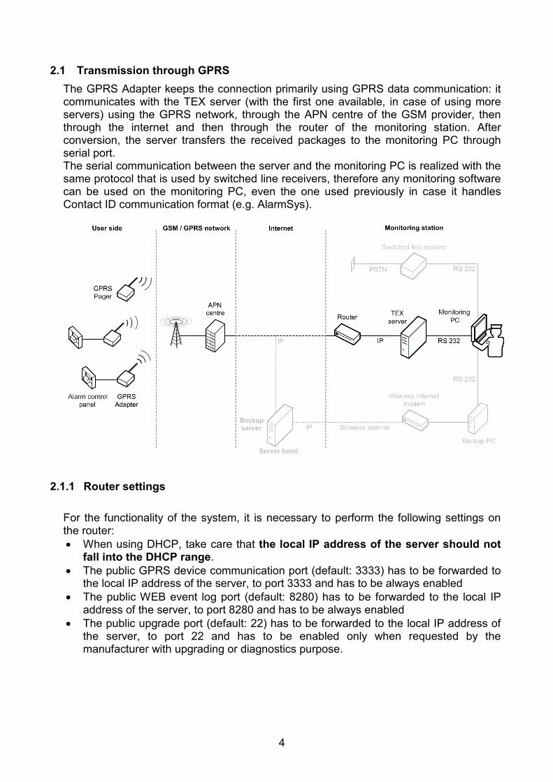
2.1 Transmission through GPRS The GPRS Adapter keeps the connection primarily using GPRS data communication: it communicates with the TEX server (with the first one available, in case of using more servers) using the GPRS network, through the APN centre of the GSM provider, then through the internet and then through the router of the monitoring station. After conversion, the server transfers the received packages to the monitoring PC through serial port. The serial communication between the server and the monitoring PC is realized with the same protocol that is used by switched line receivers, therefore any monitoring software can be used on the monitoring PC, even the one used previously in case it handles Contact ID communication format (e.g. AlarmSys).
2.1.1 Router settings For the functionality of the system, it is necessary to perform the following settings on the router: • When using DHCP, take care that the local IP address of the server should not
fall into the DHCP range. • The public GPRS device communication port (default: 3333) has to be forwarded to
the local IP address of the server, to port 3333 and has to be always enabled • The public WEB event log port (default: 8280) has to be forwarded to the local IP
address of the server, to port 8280 and has to be always enabled • The public upgrade port (default: 22) has to be forwarded to the local IP address of
the server, to port 22 and has to be enabled only when requested by the manufacturer with upgrading or diagnostics purpose.

5
2.2 Transmission in reserve GPRS mode In case the server (or any of the servers, if using more than one) is not operating or cannot be accessed through the internet because of failure or maintenance, the GPRS Adapter connects and communicates with the Backup server. The Backup server placed in a distant server hotel is connected to the Backup PC using landline or wireless (GPRS with HSDPA modem) internet connection. For security reasons it is recommended the use of the wireless internet, in case the landline internet is not independent from the one used by the primary servers. Maintenance of the connection and the forwarding of the data received from the Backup server to the physical serial port is performed by the GPRS COM Port software, installed and started previously on the Backup PC. Insertion of the Backup PC is not obligatory, but it is strongly recommended to avoid the direct exposition of the monitoring PC to eventual attacks coming from the internet. In case the Backup PC is not used, then to maintain the continuous internet connection use the GPRS VPORT software (on the monitoring PC) instead of the GPRS COM Port software. The Backup PC should be an office machine, capable to use Windows XP or Windows Vista operating system. The Backup PC has to be connected to a free serial port of the monitoring PC using a null modem cable (in case there is no free serial port, the monitoring PC is necessary to be expanded). The monitoring software receives the signals using this serial port. For the independent internet connection of the Backup PC can be a good solution the mobile internet package of any GSM service provider. These packages contain a wireless internet modem that can be quickly and easily installed and used on USB port with Windows operating system. You can also calculate with almost 100Mbyte data traffic due to the frequent connection controlling communication between the Backup PC and the Backup server, consider this too when choosing the GPRS internet package.
6
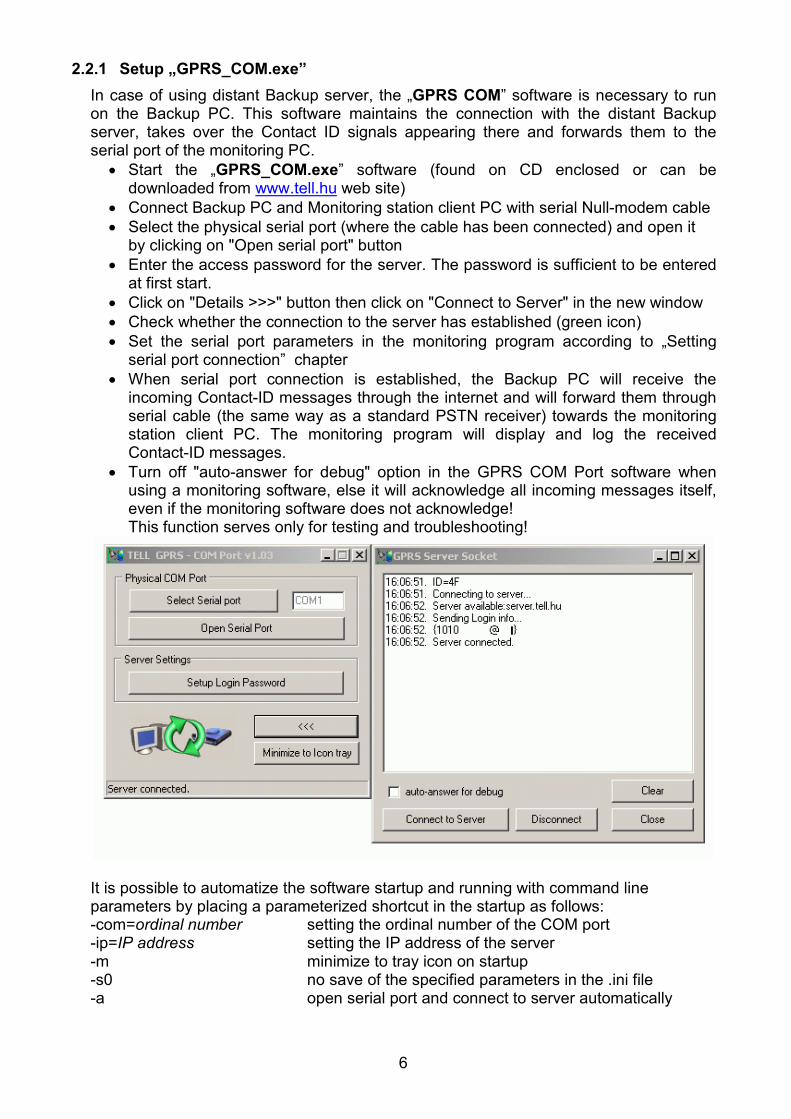
2.2.1 Setup „GPRS_COM.exe” In case of using distant Backup server, the „GPRS COM” software is necessary to run on the Backup PC. This software maintains the connection with the distant Backup server, takes over the Contact ID signals appearing there and forwards them to the serial port of the monitoring PC.
• Start the „GPRS_COM.exe” software (found on CD enclosed or can be downloaded from www.tell.hu web site)
• Connect Backup PC and Monitoring station client PC with serial Null-modem cable • Select the physical serial port (where the cable has been connected) and open it
by clicking on "Open serial port" button • Enter the access password for the server. The password is sufficient to be entered
at first start. • Click on "Details >>>" button then click on "Connect to Server" in the new window • Check whether the connection to the server has established (green icon) • Set the serial port parameters in the monitoring program according to „Setting
serial port connection” chapter • When serial port connection is established, the Backup PC will receive the
incoming Contact-ID messages through the internet and will forward them through serial cable (the same way as a standard PSTN receiver) towards the monitoring station client PC. The monitoring program will display and log the received Contact-ID messages.
• Turn off "auto-answer for debug" option in the GPRS COM Port software when using a monitoring software, else it will acknowledge all incoming messages itself, even if the monitoring software does not acknowledge! This function serves only for testing and troubleshooting!
It is possible to automatize the software startup and running with command line parameters by placing a parameterized shortcut in the startup as follows: -com=ordinal number setting the ordinal number of the COM port -ip=IP address setting the IP address of the server -m minimize to tray icon on startup -s0 no save of the specified parameters in the .ini file -a open serial port and connect to server automatically

7
The program first loads the content of the .ini file as default setting, then modifies the settings with the parameters specified in the command line. For automatic startup the .ini file has to contain already the access password to the server. For this set the password in the program, click "Yes" to save it, then close the application. This way the password will be saved in the .ini file in a coded format. Example of use: GPRS_COM.exe -com=4 -ip=193.28.86.102 -m -s0 –a The use of GPRS VPORT program is similar to GPRS COM Port, the difference is that the VPORT program runs on the same PC as the monitoring software and the communication between them is performed through the virtual serial port created by the VPORT program.
2.3 Transmission when GPRS connection fails When the GPRS Adapter is unable to establish GPRS data connection with any of the servers, then it communicates with the switched line receiver of the monitoring station using GSM voice call.
In case of transmission through GSM voice call, respectively if the device that receives the signals on the switched line receiver's side is a GSM Adapter, an increased signal delay can be expected. This delay is varying, estimated between 50-400ms. This means that due to the GSM network delay it will be probably necessary to modify the timings on the receiver that has originally been designed for landline. Due to this it may happen that after the receiver acknowledges a Contact ID signal will wait for the following Contact ID signal only for the time defined by the standard. However, in case of transmission through GSM the acknowledgement signal emitted to the respective Contact ID signal will be received by the alarm control panel with the delay of the GSM network, then the following Contact ID signal launched to this effect will also be received with delay by the monitoring station. Improper setting or the use of an outdated receiver that cannot be parameterized, may cause hang-up of the line by the receiver before receiving the newer signal. To avoid possible technical problems and to assure performance of the necessary settings please contact the manufacturer of the given receiver.

8
3 Monitoring software settings
3.1 Setting serial port connection In the monitoring program serial connection should be set as follows:
• Baud Rate: 9600 • Data bits: 8 • Parity: No • Stop bits: 1
e.g. in Alarm-Sys software:
3.2 Event code settings Events and Contact ID codes generated by the GPRS server:
Contact-ID code Event E361 Internet1 connection failure E362 Internet2 connection failure E363 LAN connection failure R361 Internet1 connection restored R362 Internet2 connection restored R363 LAN connection restored
The server transmits the restoration events as well. e.g: E361, when internet1 connection failure occurs, then R361 when connection restores. In some monitoring software E (new event) is 1 and R (event restoration) is 3. The user ID of the server towards the monitoring software is: 9999 Events and Contact ID codes generated by the GPRS server, but transmitted with the user ID set in the GPRS device:
Contact-ID code Event E360 GPRS test report timeout R360 GPRS test report restored

9
After connecting to the server, the GPRS device informs the server about the set GPRS test report timing and user ID, respectively sends the first GPRS test report (alive test signal). When the server detects that the set GPRS test report timing has expired since the last test report, waits 3 minutes and if it does not receive test report during this, it generates the GPRS test report timeout message with the E360 Contact ID code and with the user ID set in the GPRS device. For easier identification, the events can be named according to the above tables in the monitoring software (e.g. in AlarmSys software):

10
4 GPRS Settings For setting the GPRS Adapter a PC is necessary with Windows operating system (Windows XP recommended) and the two programming software found on the CD enclosed:
• GPRS_setup.exe: for server parameter settings through USB or internet/GPRS • Remoter software for installer settings through USB or internet/GPRS (further
details in „Installer settings” chapter)
4.1 Performing GPRS settings via USB connection
• Start „GPRS_Setup.exe” program (found on CD enclosed) • Language can be selected by clicking on the middle cell of the row on the bottom
of the window (Magyar / English) • Enter the module's serial number in the second cell of "Serial nr." row (found in the
framed part of the label on the back of the module) • Enter the module's own password (found in text file on the CD enclosed) • Select USB window • Power off the module (disconnect from power supply) • If you have already connected the module to PC then disconnect the USB cable • Enable „AUTO USB” function or select manually the serial USB port to be used
after pressing „COM Select” button • Click on „Connect” button • Connect the module to the PC using USB cable (current settings will automatically
download from the module) • Details about settings can be found in " GPRS parameter setting details " chapter

11
4.2 Performing GPRS settings via internet/GPRS connection • Start „GPRS_Setup.exe” program (found on CD enclosed) • Language can be selected by clicking on the middle cell of the row on the bottom
of the window (Magyar / English) • Enter the module's serial number in the second cell of "Serial nr." row (found in the
framed part of the label on the back of the module) • Enter the module's own password (found in text file on the CD enclosed) • Select GPRS window • Enter the GPRS server's IP address • Press „Connect” button • When connection has established, press "Read settings from module" button to
download current settings from the module • After the desired settings have been performed, press "Write settings into the
module" button and wait till the uploading progress bar shows end of processing • Perform module restart by pressing "Restart the module" button since the new
settings will take effect only after restart • Connection can be interrupted if necessary at anytime during communication by
pressing "Stop" button • Details about settings can be found in "GPRS parameter setting details" chapter

12
4.3 GPRS parameter setting details • In a few seconds the current GPRS settings will download automatically from the
module • GPRS settings can be loaded from file by pressing "Load from file" button and can
be saved to file by pressing "Save to file" button. • Load settings or perform the desired changes • „General settings”:
Enter the APN name in „APN1” field (e.g.: internet – in case of T-Mobile public APN service or the name supplied by your GSM service provider). Specification of User ID and Password is only required for dedicated APN.
If you wish the module to operate only with the SIM card inserted (module protection), then enable "FIX SIM" option. In this case when the module restarts it will register the inserted SIM card's serial number and hereto will operate only with that specific SIM !
If you wish the module to operate with other SIM cards as well then leave the "PIN" field blank and do not enable "FIX SIM" option but disable PIN code request on the SIM card to be placed in the module.
If you wish to prohibit the use of the SIM card in other devices (card protection), then enter the card's PIN code in the "PIN" field and enable PIN code request on the SIM card.
"PIN" and "FIX SIM" options can also be used simultaneously. If a module has been previously used with "FIX SIM" option enabled and you
still wish to replace it's SIM card, then first upload the settings to the module with "FIX SIM" option disabled, replace the SIM card and restart the module. After the module restarts with the new SIM card, it is possible to enable "FIX SIM" option again if needed.
• „IP Addresses” : „Primary Server IP A” :
• Enter the IP address of the monitoring station’s internet connection (has to be a fixed IP address supplied by the internet provider)
• Select „APN1” • Set „Port” 3333
„1. Backup Server IP”: • Set backup server IP address 193.28.86.102 (this is the TELL test server
IP address) • Select „APN1” • Set „Port” 3333
• "Frequency of GPRS test report messages" : the frequency of GPRS test report messages sent by the module to test the existence of GPRS connection (adjustable in minutes, default setting: 3 min)
• If you have ensured that the parameters you have set are correct, press „Write settings into the module” button to upload the settings to the module
• Wait a few seconds till the uploading procedure is completed and the progress bar shows end of processing
• In case of programming via internet/GPRS, the new settings will take effect only after pressing "Restart the module" button !
• When programming is finished, disconnect the USB cable if USB connection has been used. In case of programming via internet/GPRS the software can be exited.

13
GPRS Adapters purchased later than January 1, 2008, are capable to communicate with the server using dynamic IP address as well. This makes possible the use of secondary or backup connection on internet connection based on dynamic IP address. In this case the primary and secondary DNS server addresses (supplied by your internet service provider) are necessary to be specified in the corresponding fields.
5 Installer settings
5.1 Program language The language of the program can be selected by clicking on the language icons in the bottom right corner of the program window.
5.2 Setting parameters using USB serial port connection • Start „ GPRS_Adapter_vxxx.exe” remoter software • Select connection via USB in the “Connection” window • Connect the module to the PC using the enclosed USB cable • When connection is established a green tick icon appears in the upper right corner
of the program window and module version is displayed in the program header • When programming is finished, disconnect the USB cable from the module

14
5.3 Setting parameters using internet/GPRS connection • Start „GPRS_Adapter_vxxx.exe” program • Select connection via IP (internet) in the “Connection” window • Enter the server’s IP address and the module’s serial number • Enter the WEB connection password • Press „Connect to server” button to establish connection • When connection is established a green tick icon appears in the upper right corner
of the program window and module version is displayed in the program header • When programming is finished press „Disconnect from server” button.

15
5.4 Module state monitoring When connected, the module’s current state can be monitored in the “Module state” window. The following information are displayed: the availability of landline phone, state of the input, the GSM line state, the GSM signal strength and the module state messages.
PSTN Line: if there is a PSTN phone line connected to the correspondent module terminals, then it is displayed whether it is available or not
IN1: shows the state of the IN contact input GSM line state: displays the state of the GSM line, whether it is in use or not GSM signal strength: displays the current GSM signal strength on a 31-point graphical
scale Module version: the version of the connected module is displayed in the header
of the program window. The example in the picture above shows the following information:
GPRS Adapter Mini: module type v2.45: firmware version 2009.03.31: firmware date (31.03.2009)

16
5.4.1 Communication details By pressing the “Communication details” button a new window appears where the tasks and processes running in the module can be traced.
In the left side of the window (divided part) the bidirectional communication is displayed, while in the right side the module’s internal processes are shown.
Clear windows: clears the content of all windows (does not have effect on the module’s operation, only on display)
Save to file: saves the whole content of all windows to text file
Stop/Start: stops and starts the data flow being displayed (does not have effect on the module’s operation)
Close: closes the communication details window.

17
5.5 Parameter settings In this window saved settings can be loaded from files, saved to files or loaded to or from the module or compared using the corresponding icon buttons
5.5.1 Monitoring settings In this window monitoring station settings can be performed.
Operation in case of GPRS connection fault: „Secondary reporting method in case of GPRS fault” The following three processes will be performed independently from any settings: 1. If there is no GSM network available but there is an alive PSTN line, it immediately
switches to PSTN line 2. If GSM network is available but the module still tries to find an available server and
there is an alive PSTN line connected, then it switches to PSTN till finding a server. 3. If the server is found and connection is established, it immediately disconnects from
PSTN line (if existed). (The call in progress can be interrupted, however it does not cause any message loss, because the alarm control panel will repeat the unconfirmed events.)
In case „Report all events through GSM voice call” is selected: If GSM network is available and tried to access all servers without success, then it switches to GSM voice call, that is it interrupts the PSTN connection if existed. (The call in progress can be interrupted, however it does not cause any message loss, because the alarm control panel will repeat the unconfirmed events.)

18
In case „Report through GSM voice call only the events listed below ” is selected: If GSM network is available and tried to access all servers without success, then it emits the handshake and acknowledges all events (these will be lost) up to the point until it finds one that is in the list. If it finds an event that is in the list, it will not acknowledge it, and at the next dial the monitoring station will be notified through GSM voice call. The event codes in the list must consist of 4 hexadecimal digits each, where the first digit makes the difference between new event ("1") and restoration event ("3"). When entering event codes in the list, code groups can be specified as well with the use of " " character within the codes. This means it is indifferent what character is received from the alarm control panel in the place substituted with " " character but the rest of the code corresponds to the one in the list, the relevant event will be transmitted.
In case of selecting „Don’t use GSM voice call, use PSTN if available”, only the first three processes will be fulfilled. In „Central station’s phone number” field enter the monitoring station’s telephone number (which the alarm control panel will dial) in a form the number can be successfully dialed from a mobile phone as well. The module will monitor the line and when the alarm control panel dials this number, the module responds itself and simulates a monitoring station. If no PSTN line is used, leave this telephone number field blank and enter 0123 instead of monitoring station number into the alarm control panel. The module will always react when the alarm control panel will dial 0123.
5.5.2 Stand-alone CID reports In this window events sent directly by the module can be configured.

19
"User ID": has to be the same as the user ID set in the alarm control panel "Contact-ID event codes":
• "IN1 contact": If input IN1 is activated, an event with the specified event code will be generated by the module. By default this input is set NO (normally open), but can be set to NC as well by enabling „IN1 is normally closed (NC)” option. It is also possible to report the restoration of the input by enabling „Report IN1 restore as well” option.
• "PSTN fault": in case of PSTN fault an event with the code specified here will be generated by the module. If no PSTN line is used, leave this field blank.
5.5.3 BELL 103 The module is able to receive data calls initiated by GSM modems (T.E.L.L. GT64 is recommended), through which the connected alarm control panel becomes remote programmable (BELL 103/V.21 format). Concerning remote programming, the list of supported alarm control panels can be viewed on www.tell.hu website. In this window the management of incoming GSM data calls can be configured. The setting provides possibility of limitation of incoming data calls to specified phone numbers. If phone number filtering is selected, the module rejects all incoming GSM data calls which are not initiated from the specified phone numbers.
When settings are done, load the data to the module using the PC->Microchip button.

20
5.6 View event log on the GPRS server's web site The GPRS server's event log can be displayed with an internet browser (Internet Explorer is recommended) in the following manner: if the fixed IP address on which the GPRS server can be accessed from outside is e.g. 195.196.197.198, then the following address has to be entered in the browser: http://195.196.197.198:8280 The server requests the access code, which can be found on the printed GPRS Datasheet supplied with the system and on the CD enclosed, in the CODES.TXT file (e.g. 2FEB-CADE-32D4-EG68-4F11):
After entering the valid access code, the browser downloads the event log from the server for the last 24 hours:
In each row an event logged by the server can be seen, with the following details: • Date: event's date (yyyy-mm-dd) and time (hh:mm:ss) • Module name: event's source (TEX Server or Serial Module that is a module also
running on the server, performing the serial communication) • Category:
o Info: information (e.g. incoming Contact ID message) o Successful: the Contact ID message has been successfully delivered to the
monitoring software o Warning: e.g. GPRS test report absence or re-establish warning o Failed: the Contact ID message delivery to the monitoring software has failed
• Client ID: monitoring station identifier/GPRS device identifier serial number • Event: event description, the following messages can figure in square brackets: event
details e.g. characters of the Contact ID message, IP address etc. On the top of the event list, in the field next to "Client ID" can be entered the last three characters of the serial number of a GPRS device (e.g. 815 for device 0815, as it figures in the list). This way the list can be filtered to that specific device after pressing the "Reload Page" button.

21
In the field next to "Hours" can be specified how many hours of events to be displayed retrospectively in the list, after pressing the "Reload Page" button. To turn off filtering (display all events) clear the "Client ID" field then press "Reload Page" button. To exit and return to login page press "Logout" button.
5.7 Setup alarm control panel • Contact-ID communication format has to be set in the alarm control panel
connected to the module • The monitoring station’s telephone number (which the alarm control panel will dial)
has to be set in the „MINI_GPRS_Prog” program on „Central station’s phone number” page. The module will react to this number.
• If no PSTN line is used and signaling through GSM voice call is not necessary as backup possibility, then it is not necessary to enter a monitoring station telephone number in the module and it reacts when the alarm control panel dials 0123. In this case it is sufficient to set 0123 as monitoring station phone number in the alarm control panel.
6 External elements and functions of the GPRS Adapter
6.1 SIM card case The cover can be opened by pulling horizontally towards the LED display on its marked end. Insert the SIM card here and replace the cover.
6.2 LED signals
Red is continuously lit GSM network is not available or telephone power up / restart is in progress.
Red and green blink slowly and alternately (in about 1 second pace) The uploaded data is faulty
Red and green blink fast and alternately Data up/download is in progress Red and green blink at the same time impulsively (a short blink in about every 1,5 seconds)
GSM network is available but there is no GPRS connection with the server yet.
Green blinks impulsively (a short blink in about every 1,5 seconds) Red is not lit.
GPRS connection is ready, connected to the server.
6.3 Connecting antenna The antenna can be connected to an FME (pin) connector. The antenna supplied with the module provides good transmission under normal reception circumstances. In case of occasionally occurring signal strength problems or/and wave interference (fading), use another (directed) type of antenna or find a more suitable place for the Adapter.

22
6.4 Connector terminals:
V+ Supply voltage 9-24 V DC V- Supply voltage negative polarity (GND) G1 Simulated line output from the GSM system (to the alarm control panel’s TIP input) G2 Simulated line output from the GSM system (to the alarm control panel’s RING input) T1 Wired phone line (PSTN) input T2 Wired phone line (PSTN) input IN Contact input for sending stand alone message (to activate, connect to V-) S3 Not used S2 Not used S5 Not used Important! If the metal casing of the control panel in which the module is mounted is
connected to the protective ground then it is necessary to connect that protective ground to the GPRS Adapter module's V- connector as well.
7 Installation guide
Before installation verify the future environment of the Adapter: • Check the GSM signal strength using your mobile phone. It may happen that the
signal strength is not sufficient in the desired installation place. In this case you have possibility to change the planned installation place before mounting.
• Do not mount the unit in places where it can be affected by strong electromagnetic disturbances (e.g. near electric motors, etc.).
• Do not mount the unit in wet places or places with high degree of humidity.
7.1 Mounting Suggested installation method: the GPRS Adapter should be placed into the same metal housing as the alarm control panel. Drill a hole on the metal housing for the FME connector. Choose the drill size appropriate for the FME base part. Fix the FME base with the enclosed screw nuts into the housing. Ensure that the FME base and the metal housing has galvanic connection. In case of plastic housing and weak GSM signal strength it may be necessary to use another (directed) type of antenna.
7.2 Putting into operation • Make sure the SIM card is placed into its case properly. • Make sure the antenna is fixed in the Adapter properly. • Make sure the wiring is done as earlier instructed. • The device can be powered up (9-24V DC). Make sure that the power source is
sufficient at the load of both the alarm control panel and the Adapter. The quiescent current of the Adapter is 100mA, however it can reach up to 500mA during communication.

23
8 Technical details
8.1 Technical specification Supply voltage: 9-24 VDC Maximum current consumption: 500mA @ 12VDC, 250mA @ 24VDC Operating temperature: -20ºC - +70ºC Transmission frequency: GSM 900MHz /1800MHz Dimensions: 84 x 72 x 32mm Net weight: 200g Gross weight (packed): 300g
8.2 Generated telephone line specification Line voltage: 48 V Line current: 25 mA Line impedance: 600 Ohm Ringing voltage: ±72V (25 Hz) Dial tone: 400 Hz
8.3 Content of the package • GPRS Adapter + terminal connector • GSM 900MHz / 1800MHz antenna • User manual, warranty card • CD • USB A-B cable